WO2017222243A1 - 복수의 디스플레이를 포함하는 전자 장치 - Google Patents
복수의 디스플레이를 포함하는 전자 장치 Download PDFInfo
- Publication number
- WO2017222243A1 WO2017222243A1 PCT/KR2017/006294 KR2017006294W WO2017222243A1 WO 2017222243 A1 WO2017222243 A1 WO 2017222243A1 KR 2017006294 W KR2017006294 W KR 2017006294W WO 2017222243 A1 WO2017222243 A1 WO 2017222243A1
- Authority
- WO
- WIPO (PCT)
- Prior art keywords
- housing
- touch screen
- hinge structure
- gear
- screen display
- Prior art date
- Legal status (The legal status is an assumption and is not a legal conclusion. Google has not performed a legal analysis and makes no representation as to the accuracy of the status listed.)
- Ceased
Links
Images




Classifications
-
- G—PHYSICS
- G06—COMPUTING OR CALCULATING; COUNTING
- G06F—ELECTRIC DIGITAL DATA PROCESSING
- G06F1/00—Details not covered by groups G06F3/00 - G06F13/00 and G06F21/00
- G06F1/16—Constructional details or arrangements
- G06F1/1613—Constructional details or arrangements for portable computers
- G06F1/1633—Constructional details or arrangements of portable computers not specific to the type of enclosures covered by groups G06F1/1615 - G06F1/1626
- G06F1/1637—Details related to the display arrangement, including those related to the mounting of the display in the housing
- G06F1/1641—Details related to the display arrangement, including those related to the mounting of the display in the housing the display being formed by a plurality of foldable display components
-
- G—PHYSICS
- G06—COMPUTING OR CALCULATING; COUNTING
- G06F—ELECTRIC DIGITAL DATA PROCESSING
- G06F1/00—Details not covered by groups G06F3/00 - G06F13/00 and G06F21/00
- G06F1/16—Constructional details or arrangements
- G06F1/1601—Constructional details related to the housing of computer displays, e.g. of CRT monitors, of flat displays
- G06F1/1605—Multimedia displays, e.g. with integrated or attached speakers, cameras, microphones
-
- G—PHYSICS
- G06—COMPUTING OR CALCULATING; COUNTING
- G06F—ELECTRIC DIGITAL DATA PROCESSING
- G06F1/00—Details not covered by groups G06F3/00 - G06F13/00 and G06F21/00
- G06F1/16—Constructional details or arrangements
- G06F1/1613—Constructional details or arrangements for portable computers
- G06F1/1615—Constructional details or arrangements for portable computers with several enclosures having relative motions, each enclosure supporting at least one I/O or computing function
- G06F1/1616—Constructional details or arrangements for portable computers with several enclosures having relative motions, each enclosure supporting at least one I/O or computing function with folding flat displays, e.g. laptop computers or notebooks having a clamshell configuration, with body parts pivoting to an open position around an axis parallel to the plane they define in closed position
-
- G—PHYSICS
- G06—COMPUTING OR CALCULATING; COUNTING
- G06F—ELECTRIC DIGITAL DATA PROCESSING
- G06F1/00—Details not covered by groups G06F3/00 - G06F13/00 and G06F21/00
- G06F1/16—Constructional details or arrangements
- G06F1/1613—Constructional details or arrangements for portable computers
- G06F1/1615—Constructional details or arrangements for portable computers with several enclosures having relative motions, each enclosure supporting at least one I/O or computing function
- G06F1/1616—Constructional details or arrangements for portable computers with several enclosures having relative motions, each enclosure supporting at least one I/O or computing function with folding flat displays, e.g. laptop computers or notebooks having a clamshell configuration, with body parts pivoting to an open position around an axis parallel to the plane they define in closed position
- G06F1/1618—Constructional details or arrangements for portable computers with several enclosures having relative motions, each enclosure supporting at least one I/O or computing function with folding flat displays, e.g. laptop computers or notebooks having a clamshell configuration, with body parts pivoting to an open position around an axis parallel to the plane they define in closed position the display being foldable up to the back of the other housing with a single degree of freedom, e.g. by 360° rotation over the axis defined by the rear edge of the base enclosure
-
- G—PHYSICS
- G06—COMPUTING OR CALCULATING; COUNTING
- G06F—ELECTRIC DIGITAL DATA PROCESSING
- G06F1/00—Details not covered by groups G06F3/00 - G06F13/00 and G06F21/00
- G06F1/16—Constructional details or arrangements
- G06F1/1613—Constructional details or arrangements for portable computers
- G06F1/1633—Constructional details or arrangements of portable computers not specific to the type of enclosures covered by groups G06F1/1615 - G06F1/1626
- G06F1/1635—Details related to the integration of battery packs and other power supplies such as fuel cells or integrated AC adapter
-
- G—PHYSICS
- G06—COMPUTING OR CALCULATING; COUNTING
- G06F—ELECTRIC DIGITAL DATA PROCESSING
- G06F1/00—Details not covered by groups G06F3/00 - G06F13/00 and G06F21/00
- G06F1/16—Constructional details or arrangements
- G06F1/1613—Constructional details or arrangements for portable computers
- G06F1/1633—Constructional details or arrangements of portable computers not specific to the type of enclosures covered by groups G06F1/1615 - G06F1/1626
- G06F1/1637—Details related to the display arrangement, including those related to the mounting of the display in the housing
- G06F1/1647—Details related to the display arrangement, including those related to the mounting of the display in the housing including at least an additional display
-
- G—PHYSICS
- G06—COMPUTING OR CALCULATING; COUNTING
- G06F—ELECTRIC DIGITAL DATA PROCESSING
- G06F1/00—Details not covered by groups G06F3/00 - G06F13/00 and G06F21/00
- G06F1/16—Constructional details or arrangements
- G06F1/1613—Constructional details or arrangements for portable computers
- G06F1/1633—Constructional details or arrangements of portable computers not specific to the type of enclosures covered by groups G06F1/1615 - G06F1/1626
- G06F1/1637—Details related to the display arrangement, including those related to the mounting of the display in the housing
- G06F1/1652—Details related to the display arrangement, including those related to the mounting of the display in the housing the display being flexible, e.g. mimicking a sheet of paper, or rollable
-
- G—PHYSICS
- G06—COMPUTING OR CALCULATING; COUNTING
- G06F—ELECTRIC DIGITAL DATA PROCESSING
- G06F1/00—Details not covered by groups G06F3/00 - G06F13/00 and G06F21/00
- G06F1/16—Constructional details or arrangements
- G06F1/1613—Constructional details or arrangements for portable computers
- G06F1/1633—Constructional details or arrangements of portable computers not specific to the type of enclosures covered by groups G06F1/1615 - G06F1/1626
- G06F1/1675—Miscellaneous details related to the relative movement between the different enclosures or enclosure parts
- G06F1/1681—Details related solely to hinges
-
- G—PHYSICS
- G06—COMPUTING OR CALCULATING; COUNTING
- G06F—ELECTRIC DIGITAL DATA PROCESSING
- G06F1/00—Details not covered by groups G06F3/00 - G06F13/00 and G06F21/00
- G06F1/16—Constructional details or arrangements
- G06F1/1613—Constructional details or arrangements for portable computers
- G06F1/1633—Constructional details or arrangements of portable computers not specific to the type of enclosures covered by groups G06F1/1615 - G06F1/1626
- G06F1/1684—Constructional details or arrangements related to integrated I/O peripherals not covered by groups G06F1/1635 - G06F1/1675
- G06F1/1686—Constructional details or arrangements related to integrated I/O peripherals not covered by groups G06F1/1635 - G06F1/1675 the I/O peripheral being an integrated camera
-
- G—PHYSICS
- G06—COMPUTING OR CALCULATING; COUNTING
- G06F—ELECTRIC DIGITAL DATA PROCESSING
- G06F1/00—Details not covered by groups G06F3/00 - G06F13/00 and G06F21/00
- G06F1/16—Constructional details or arrangements
- G06F1/1613—Constructional details or arrangements for portable computers
- G06F1/1633—Constructional details or arrangements of portable computers not specific to the type of enclosures covered by groups G06F1/1615 - G06F1/1626
- G06F1/1684—Constructional details or arrangements related to integrated I/O peripherals not covered by groups G06F1/1635 - G06F1/1675
- G06F1/1688—Constructional details or arrangements related to integrated I/O peripherals not covered by groups G06F1/1635 - G06F1/1675 the I/O peripheral being integrated loudspeakers
-
- G—PHYSICS
- G06—COMPUTING OR CALCULATING; COUNTING
- G06F—ELECTRIC DIGITAL DATA PROCESSING
- G06F3/00—Input arrangements for transferring data to be processed into a form capable of being handled by the computer; Output arrangements for transferring data from processing unit to output unit, e.g. interface arrangements
- G06F3/01—Input arrangements or combined input and output arrangements for interaction between user and computer
- G06F3/03—Arrangements for converting the position or the displacement of a member into a coded form
- G06F3/041—Digitisers, e.g. for touch screens or touch pads, characterised by the transducing means
-
- G—PHYSICS
- G06—COMPUTING OR CALCULATING; COUNTING
- G06F—ELECTRIC DIGITAL DATA PROCESSING
- G06F3/00—Input arrangements for transferring data to be processed into a form capable of being handled by the computer; Output arrangements for transferring data from processing unit to output unit, e.g. interface arrangements
- G06F3/01—Input arrangements or combined input and output arrangements for interaction between user and computer
- G06F3/048—Interaction techniques based on graphical user interfaces [GUI]
- G06F3/0487—Interaction techniques based on graphical user interfaces [GUI] using specific features provided by the input device, e.g. functions controlled by the rotation of a mouse with dual sensing arrangements, or of the nature of the input device, e.g. tap gestures based on pressure sensed by a digitiser
- G06F3/0488—Interaction techniques based on graphical user interfaces [GUI] using specific features provided by the input device, e.g. functions controlled by the rotation of a mouse with dual sensing arrangements, or of the nature of the input device, e.g. tap gestures based on pressure sensed by a digitiser using a touch-screen or digitiser, e.g. input of commands through traced gestures
-
- H—ELECTRICITY
- H04—ELECTRIC COMMUNICATION TECHNIQUE
- H04M—TELEPHONIC COMMUNICATION
- H04M1/00—Substation equipment, e.g. for use by subscribers
- H04M1/02—Constructional features of telephone sets
- H04M1/0202—Portable telephone sets, e.g. cordless phones, mobile phones or bar type handsets
- H04M1/0206—Portable telephones comprising a plurality of mechanically joined movable body parts, e.g. hinged housings
- H04M1/0208—Portable telephones comprising a plurality of mechanically joined movable body parts, e.g. hinged housings characterized by the relative motions of the body parts
- H04M1/0214—Foldable telephones, i.e. with body parts pivoting to an open position around an axis parallel to the plane they define in closed position
- H04M1/0216—Foldable in one direction, i.e. using a one degree of freedom hinge
- H04M1/022—The hinge comprising two parallel pivoting axes
-
- H—ELECTRICITY
- H04—ELECTRIC COMMUNICATION TECHNIQUE
- H04M—TELEPHONIC COMMUNICATION
- H04M1/00—Substation equipment, e.g. for use by subscribers
- H04M1/02—Constructional features of telephone sets
- H04M1/0202—Portable telephone sets, e.g. cordless phones, mobile phones or bar type handsets
- H04M1/026—Details of the structure or mounting of specific components
- H04M1/0266—Details of the structure or mounting of specific components for a display module assembly
- H04M1/0268—Details of the structure or mounting of specific components for a display module assembly including a flexible display panel
- H04M1/0269—Details of the structure or mounting of specific components for a display module assembly including a flexible display panel mounted in a fixed curved configuration, e.g. display curved around the edges of the telephone housing
-
- G—PHYSICS
- G06—COMPUTING OR CALCULATING; COUNTING
- G06F—ELECTRIC DIGITAL DATA PROCESSING
- G06F2203/00—Indexing scheme relating to G06F3/00 - G06F3/048
- G06F2203/041—Indexing scheme relating to G06F3/041 - G06F3/045
- G06F2203/04102—Flexible digitiser, i.e. constructional details for allowing the whole digitising part of a device to be flexed or rolled like a sheet of paper
-
- H—ELECTRICITY
- H04—ELECTRIC COMMUNICATION TECHNIQUE
- H04M—TELEPHONIC COMMUNICATION
- H04M1/00—Substation equipment, e.g. for use by subscribers
- H04M1/02—Constructional features of telephone sets
- H04M1/03—Constructional features of telephone transmitters or receivers, e.g. telephone hand-sets
-
- H—ELECTRICITY
- H04—ELECTRIC COMMUNICATION TECHNIQUE
- H04M—TELEPHONIC COMMUNICATION
- H04M2250/00—Details of telephonic subscriber devices
- H04M2250/16—Details of telephonic subscriber devices including more than one display unit
Definitions
- Various embodiments of the present invention relate to an electronic device, for example, to an electronic device that is folded or unfolded with a plurality of display devices coupled by a hinge.
- An electronic device is a device that performs a specific function according to a program installed, such as an electronic notebook, a portable multimedia player, a mobile communication terminal, a tablet PC, a video / audio device, a desktop / laptop computer, a car navigation system, etc. Can mean.
- electronic devices may output stored information as sound or an image.
- various functions may be installed in one electronic device such as a mobile communication terminal. For example, not only communication functions, but also entertainment functions such as games, multimedia functions such as music / video playback, communication and security functions for mobile banking, calendar management or electronic wallet, etc. It is.
- Such electronic devices are being miniaturized to be conveniently carried by a user.
- the size of the display of the electronic device is in a trade-off relationship with the miniaturization of the electronic device.
- one display can display a continuous image through the two displays to realize a large screen, and the two displays are folded together.
- the portability can be increased.
- the two displays may not be able to completely implement a continuous image.
- a physical space is required between the two displays, and a part of the user's body (for example, a finger or the like) may be injured between the spaces.
- an electronic device is to faithfully implement one continuous image even when two displays are unfolded.
- an electronic device is intended to prevent a part of a user's body (eg, a finger, etc.) from being caught between two displays.
- An electronic device may include a first surface and a second surface facing away from the first surface, wherein the first surface includes a first touch screen display and is viewed from above the first surface.
- the first housing comprises a first side and a second side at a first edge; A third surface and a fourth surface facing away from said third surface, said third surface comprising a second touchscreen display, said third surface extending adjacent said first edge when viewed from above said third surface;
- a second housing comprising a third side and a fourth side at two edges;
- At least one processor located in at least one of the first or second housings and electrically connected to the first touchscreen display and / or the second touchscreen display through at least one of the first or second hinge structures ; And a memory positioned in at least one of the first or second housings and electrically connected to the processor, wherein the first hinge structure and the second hinge structure include: a first housing; Allow to rotate relative
- an electronic device may include a first housing including a first touch screen display; A second housing including a second touch screen display and rotatably coupled to the first housing; A hinge structure disposed between the first housing and the second housing, the hinge structure configured to rotatably couple the first housing and the second housing with respect to each other, the first touch screen display adjacent to the hinge structure.
- the first side may be curved, and the second side of the second touch screen display adjacent to the hinge structure may be curved to face the first side of the first touch screen display.
- the first and second touch screen displays may be compared with a continuous screen implemented only by a conventional plane. It is possible to minimize the disconnection part of the screen output from.
- the first side of the first and second touch screen display is curved, so that the first side of the first and second touch screen display does not interfere with the rotation of the first and second touch screen display, Unlike the electronic device, a space for rotating the first and second touch screen displays is not required. Accordingly, in the electronic device according to various embodiments of the present disclosure, as the first side surfaces of the first and second touch screen displays are curved, a user's finger is placed between the first and second touch screen displays. It can prevent getting caught.
- FIG. 1 is an exploded perspective view illustrating a hinge structure of an electronic device according to one of various embodiments of the present disclosure.
- FIG. 2 is a perspective view illustrating a first hinge structure of an electronic device according to one of various embodiments of the present disclosure.
- FIG 3 is a perspective view illustrating a state in which a first hinge structure of an electronic device according to one of various embodiments of the present disclosure is coupled between a first housing and a second housing.
- FIG. 4 is an enlarged view illustrating an enlarged portion A shown in FIG. 3.
- FIG. 5 is a cross-sectional view illustrating a first hinge structure of an electronic device according to one of various embodiments of the present disclosure.
- FIG. 6 is a perspective view illustrating a second hinge structure of an electronic device according to one of various embodiments of the present disclosure.
- FIG. 7 is a perspective view illustrating a state in which a second hinge structure of an electronic device according to one of various embodiments of the present disclosure is coupled between a first housing and a second housing.
- FIG. 8 is an enlarged view illustrating part B of FIG. 7 enlarged.
- FIG. 9 is a cross-sectional view illustrating a second hinge structure of an electronic device according to one of various embodiments of the present disclosure.
- FIG. 10 is a cross-sectional view illustrating an electronic device according to one of various embodiments of the present disclosure.
- FIG. 11 is an enlarged view illustrating part C of FIG. 10 enlarged.
- FIG. 12 is a perspective view illustrating a flexible circuit board of an electronic device according to one of various embodiments of the present disclosure.
- FIG. 13 is a side view illustrating a flexible circuit board of an electronic device according to one of various embodiments of the present disclosure.
- FIG. 14 is a side cross-sectional view illustrating a flexible circuit board of an electronic device coupled to first and second housings according to one of various embodiments of the present disclosure.
- FIG. 15 is a rear view illustrating a flexible circuit board of an electronic device coupled to a first housing and a hinge housing according to one of various embodiments of the present disclosure.
- 16 is a front view illustrating a flexible circuit board of an electronic device according to one of various embodiments of the present disclosure coupled to a second housing and a hinge housing.
- 17 is a cross-sectional view illustrating a flexible circuit board of an electronic device coupled to a hinge housing according to one of various embodiments of the present disclosure.
- FIG. 18 is a cross-sectional view of a flexible circuit board of an electronic device according to one of various embodiments of the present disclosure, coupled to a hinge housing from another angle.
- FIG. 19 is a perspective view illustrating a state where a first surface of a first housing and a first surface of a second housing of the electronic device are in contact with each other according to various embodiments of the present disclosure.
- FIG. 20 is a left side view of FIG. 19.
- FIG. 21 is a right side view of FIG. 19.
- FIG. 22 is a perspective view illustrating a keypad of a second touch screen display of an electronic device according to one of various embodiments of the present disclosure
- FIG. 23 is a front view illustrating a state in which a second housing of an electronic device is rotated 180 degrees with respect to the first housing, according to one of various embodiments of the present disclosure.
- 24A is a rear view illustrating a state in which a second housing of an electronic device is rotated 180 degrees with respect to the first housing, according to one of various embodiments of the present disclosure.
- 24B is a rear view illustrating a state in which the second housing of the electronic device is rotated 180 degrees with respect to the first housing, according to an embodiment of the present disclosure.
- 25 is a plan view illustrating a state in which a second housing of an electronic device is rotated 180 degrees with respect to the first housing, according to one of various embodiments of the present disclosure.
- FIG. 26A is a right side view illustrating a state in which a second housing of an electronic device is rotated 180 degrees with respect to a first housing, according to one of various embodiments of the present disclosure
- FIG. 26B is a left side view illustrating a state in which a second housing of an electronic device is rotated 180 degrees with respect to the first housing, according to one of various embodiments of the present disclosure
- 27A is a bottom view illustrating a state in which a second housing of an electronic device is rotated 180 degrees with respect to the first housing, according to one of various embodiments of the present disclosure.
- FIG. 27B is an enlarged view illustrating a portion C1 of FIG. 27A enlarged.
- FIG. 27C is a bottom view illustrating a state in which a second housing of an electronic device is rotated with respect to the first housing by 0 degrees according to one of various embodiments of the present disclosure
- FIG. 27D is an enlarged view illustrating an enlarged portion C2 of FIG. 27C.
- 27E is a bottom view illustrating a state in which a second housing of an electronic device is rotated between 0 degrees and 180 degrees with respect to the first housing, according to one of various embodiments of the present disclosure.
- FIG. 27F is an enlarged view of a portion C3 of FIG. 27E enlarged.
- FIG. 28 is a cross-sectional view illustrating a state in which a second housing of an electronic device is rotated 180 degrees with respect to a first housing, according to one of various embodiments of the present disclosure
- FIG. 29 is an enlarged view illustrating a portion D shown in FIG. 28.
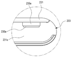
- FIG. 30 is an enlarged view illustrating a portion E illustrated in FIG. 29.
- FIG. 31 is a cross-sectional view of a camera disposed adjacent to a flash.
- FIG. 32 is a front view illustrating a camera and a flash of an electronic device according to one of various embodiments of the present disclosure.
- 34 is a rear view illustrating an electronic device according to another one of various embodiments of the present disclosure.
- 35 is a cross-sectional view taken along the line D-D 'shown in FIG.
- FIG. 36 is an enlarged view illustrating a portion G1 illustrated in FIG. 35.
- FIG. 37 is an enlarged view illustrating an enlarged portion G2 shown in FIG. 35.
- 38 is a front view illustrating an electronic device according to another one of various embodiments of the present disclosure.
- FIG. 39 is a cross-sectional view taken along the line E-E 'shown in FIG.
- FIG. 40 is an enlarged view illustrating an enlarged portion G3 illustrated in FIG. 39.
- FIG. 41 is an enlarged view of a portion G4 illustrated in FIG. 39.
- FIG. 42 is a block diagram of an electronic device according to various embodiments of the present disclosure.
- FIG 43 is a front view illustrating a state of use of the first and second touch screen displays of the electronic device according to various embodiments of the present disclosure.
- 44 is a front view illustrating one screen by a first and second touch screen display of an electronic device according to various embodiments of the present disclosure.
- 46 is a front view illustrating another usage state of the first and second touch screen displays of the electronic device according to various embodiments of the present disclosure.
- 47 is a front view illustrating still another usage state of the first and second touch screen displays of the electronic device according to various embodiments of the present disclosure.
- 48A is a front view illustrating still another use state of first and second touch screen displays of an electronic device according to various embodiments of the present disclosure.
- 48B is a front view illustrating still another use state of the first and second touch screen displays of the electronic device according to various embodiments of the present disclosure.
- 49 is a perspective view illustrating a state in which an electronic device is mounted in a longitudinal direction and mounted according to various embodiments of the present disclosure.
- 50 is a perspective view illustrating an electronic device inclinedly mounted according to various embodiments of the present disclosure.
- 51 is a perspective view illustrating a state in which a first housing of an electronic device is inclinedly mounted according to various embodiments of the present disclosure.
- FIG. 52 is a perspective view illustrating a state in which a second surface of a first housing and a fourth surface of a second housing of the electronic device face each other, according to various embodiments of the present disclosure.
- FIG. 53 is a front view of FIG. 52.
- FIG. 54 is a rear view of FIG. 52.
- FIG. 55 is a top view of FIG. 52.
- FIG. 56 is a left side view of FIG. 52.
- FIG. 57 is a right side view of FIG. 52.
- FIG. 58 is a bottom view of FIG. 52.
- FIG. 59 is a block diagram illustrating an operation sequence of rotating the first and second housings of the electronic device according to various embodiments of the present disclosure.
- 60 is a perspective view illustrating a state in which first and second housings of an electronic device are rotated between 0 degrees and 180 degrees according to various embodiments of the present disclosure.
- FIG. 61 is a perspective view illustrating a state in which first and second housings of an electronic device are rotated between 180 degrees and 360 degrees according to various embodiments of the present disclosure.
- expressions such as “having”, “may have”, “includes” or “can include” may refer to a feature such as a component, such as a numerical value, function, operation, or component. ) And does not exclude the presence of additional features.
- the expression “A or B”, “at least one of A or / and B” or “one or more of A or / and B” and the like includes all possible combinations of the items listed together. can do.
- “A or B,” “at least one of A and B,” or “at least one of A or B,” includes (1) at least one A, (2) at least one B, Or (3) both of cases including at least one A and at least one B.
- first,” “second,” “first,” or “second,” as used herein may modify various components, regardless of order and / or importance, and may configure one component in another. It is used to distinguish it from an element but does not limit its components.
- the first user device and the second user device may represent different user devices regardless of the order or importance.
- the first component may be referred to as the second component, and similarly, the second component may also be referred to as the first component.
- One component (such as a first component) is "(functionally or communicatively) coupled with / to" to another component (such as a second component) or " When referred to as “connected to”, it should be understood that any component may be directly connected to the other component or may be connected through another component (eg, a third component).
- a component e.g., a first component
- another component e.g., a second component
- no other component e.g., a third component
- FIG. 1 is an exploded perspective view illustrating a hinge structure of an electronic device according to one of various embodiments of the present disclosure.
- an electronic device 100 includes a first housing 101, a second housing 103, and hinge structures 105 and 107, and includes a hinge structure ( 105 and 107 may rotatably couple the second housing 103 and the first housing 101 to each other, so that the second housing 103 may open and close the first housing 101. .
- the hinge structures 105 and 107 may include a first hinge structure 105 and a second hinge structure 107 provided at both ends of the first housing 101 and the second housing 103, respectively. have.
- the first hinge structure 105 includes a first hinge connection portion 151, a first gear 153, a first idle gear 155, a second idle gear 156, a second gear 154, and a second hinge.
- the connection part 152, the support parts 157 and 158, and the hinge housing 150a may be included.
- the first hinge connection part 151 may be coupled to the first housing 101 by a bolt (not shown) having a first coupling hole 151a for fastening with the first housing 101.
- a screw thread may be formed on an inner surface of the first coupling hole 151 a, and the first hinge connection part 151 may be coupled to the first housing 101 by a bolt.
- a second coupling hole (not shown) corresponding to the first coupling hole 151a may be formed in the first housing 101, and the bolt is connected to the first coupling hole 151a and the second coupling hole 151a.
- the first hinge connector 151 may be coupled to the first housing 101 while being inserted into the coupling hole.
- the first hinge connection part 151 may have a third coupling hole 151b into which the first gear shaft 153a of the first gear 153 is inserted.
- the first gear shaft 153a may have a polygonal shape, and the third coupling hole 151b may have a shape corresponding to the first gear shaft 153a.
- the first gear 153 may rotate together with the first hinge connecting portion 151.
- the first idle gear 155 may be rotatably engaged with the first gear 153.
- the second idle gear 156 may be rotatably engaged with the first idle gear 155.
- the second gear 154 may be rotatably engaged with the second idle gear 156.
- the second hinge connection part 152 may be coupled to the second housing 103 by a rivet (not shown) having a fourth coupling hole 152a for fastening with the second housing 103.
- a screw thread may be formed on an inner surface of the fourth coupling hole 152a, and the second hinge connection part 152 may be coupled to the second housing 103 by a bolt.
- a fifth coupling hole (not shown) corresponding to the fourth coupling hole 152a may be formed in the second housing 103, and the bolt is connected to the fourth coupling hole 152a and the fifth coupling hole.
- the second hinge connector 152 may be coupled to the second housing 103 while being inserted into the coupling hole.
- the second hinge connector 152 may have a sixth coupling hole 152b into which the second gear shaft 154a of the second gear 154 is inserted.
- the second gear shaft 154a may have a polygonal shape, and the sixth coupling hole 152b may have a shape corresponding to the second gear shaft 154a.
- the support parts 157 and 158 may include a first support part 157 and a second support part 158 which rotatably support the first and second gears 153 and 154 and the first idle gears 155 and 156. It may include.
- the first support part 157 may include first and second idle gear shafts formed at one end of the first and second gear shafts 153a and 154a and the first and second idle gears 155 and 156.
- a plurality of first support holes 157a and 157b into which one end of 155a and 156a is inserted may be formed.
- the second support part 158 may include first and second idle gear shafts formed at the other ends of the first and second gear shafts 153a and 154a and the first and second idle gears 155 and 156.
- a plurality of second support holes 158a and 158b into which the other ends of the 155a and 156a are inserted may be formed.
- the hinge housing 150a may accommodate the first and second gears 153 and 154, the first and second idle gears 155 and 156, and the support parts 157 and 158.
- the first hinge structure 105 of the electronic device 100 is an elastic member 159 for pressing the second support portion 158 and one surface of the elastic member 159. It may further include a washer (159c) in contact with.
- the elastic member 159 may be accommodated in the hinge housing 150a and penetrate the first and second gear shafts 153a and 154a to be connected to the first and second gears 153 and 154.
- the elastic member 159 may be made of a plate spring.
- the washer 159c may be accommodated in the hinge housing 150a and penetrate the first and second gear shafts 153a and 154a to be connected to the first and second gears 153 and 154.
- a partition wall 150c may be formed in the hinge housing 150a, and the washer 159c may be disposed between the partition wall 150c and the elastic member 159.
- the elastic member 159 may press the second support part 158 while being supported by the partition wall 150c of the hinge housing 150a.
- the second hinge structure 107 includes a first hinge connector 171, a second hinge connector 172, a first gear 173, a second gear 174, a first idle gear 175, and a second idler.
- the gear 176, the support parts 177 and 178, the elastic member 179, and the hinge housing 170a may be included.
- a first coupling hole 171a and a third coupling hole 171b are formed in the first hinge connecting portion 171, and a fourth coupling hole 172a and a sixth coupling hole are formed in the second hinge connecting portion 172.
- the first gear 173 includes a first gear shaft 173a
- the second gear 174 includes a second gear shaft 174a
- the first idle gear 175 includes a first idle gear shaft 175a
- the second idle gear 176 includes a second idle gear shaft 176a
- the supports 177, 178 are provided with a first support 177.
- first support holes 177a and 177b in the first support part 177, and second support holes 178a and 178b in the second support part 178. have.
- the elastic members 179 and 179c may include a first elastic member 179 and a second elastic member 179c provided on one surface of the first elastic member 179 to the first hinge structure 105. In comparison, an elastic force for pressing the second support part 178 may be increased.
- a third support 178d is provided between the first elastic member 179 and the second support 178, and the washer 178e includes the second support 178 and the third support 178d. It may be provided between).
- the second hinge structure 107 may include a fourth support 179d, a nut 179f, and a second washer 179e.
- the fourth support part 179d may contact one surface of the second elastic member 179c.
- the nut 179f may be coupled to the first and second gear shafts 173a and 174a while contacting one surface of the fourth support part 179d. Threads are formed at the other ends of the first and second gear shafts 173a and 174a to press the fourth support part 179d while the nut 179f is fastened along the threads.
- the second washer 179e may be provided between the fourth support part 179d and the nut 179f.
- the first gear shaft 153a of the first hinge structure 105 and the first gear shaft 173a of the second hinge structure 107 form a first virtual axis A1 to form the first housing ( 101 may rotate about the first virtual axis A1 while having the first virtual axis A1.
- the second gear shaft 154a of the first hinge structure 105 and the second gear shaft 174a of the second hinge structure 107 form a second virtual axis A2 to form the second virtual shaft A2.
- the housing 103 may rotate about the first virtual axis A2 while having the second virtual axis A2.
- the second housing 103 may rotate between 0 and 360 degrees with respect to the first housing 101.
- the angle representing 0 to 360 degrees may be defined as an angle of the second housing 103 with respect to the first housing 101.
- an angle between the first housing 101 and the second housing 103 may be defined as 0 degrees.
- FIG. 2 is a perspective view illustrating a first hinge structure of an electronic device according to one of various embodiments of the present disclosure.
- the first and second gears 153 and 154 and the first and second idle gears 155 and 156 may include the first support part 157 and the second support part 158. Can rotate in engagement with each other.
- the first hinge connector 151 rotates together with the first gear 153
- the first idle gear 155 meshed with the first gear 153 rotates in the opposite direction to the first gear 153.
- the second idle gear 155 meshed with the first idle gear 155 rotates in the same direction as the first gear 153
- the second gear 154 meshed with the second idle gear 155. May rotate together with the second hinge connector 152 in a direction opposite to the first gear 153. That is, the first hinge connector 151 may rotate in the opposite direction to the second hinge connector 152.
- FIG. 3 is a perspective view illustrating a state in which a first hinge structure of an electronic device according to one of various embodiments of the present disclosure is coupled between a first housing and a second housing.
- 4 is an enlarged view illustrating an enlarged portion A shown in FIG. 3.
- 5 is a cross-sectional view illustrating a first hinge structure of an electronic device according to one of various embodiments of the present disclosure.
- the first housing 101 may include a first side portion 101b at one end of the first edge 101a, and the second housing 103 may include a second portion.
- One end of the edge 103a may include a third side 103b.
- the first hinge structure 105 may connect the first side portion 101b and the third side portion 103b.
- the first housing 101, the first side portion 101b is coupled to the first hinge connection portion 151, can rotate together with the first hinge connection portion 151, the second housing 103 ),
- the third side portion 103b may be coupled to the second hinge connecting portion 152 to rotate together with the second hinge connecting portion 152.
- the first hinge connection portion 151 is sequential to the first gear 153, the first idle gear 155, the second idle gear 156, and the second gear 154.
- the connection may rotate in a direction opposite to the rotation of the second hinge connector 152.
- the elastic member 159 is supported by the partition wall 150c of the hinge housing 150a and provides an elastic force in a first direction 1 toward the second support part 158 to provide the second support part 158. Can be pressurized. As the elastic member 159 presses the second support part 158, the second support part 158 is in surface contact with the first and second gears 153 and 154 and the first and second gears. Rotation of 153 and 154 may be limited. The elastic member 159 may limit rotation of the first housing 103 with respect to the first housing 101 by limiting rotation of the first and second gears 153 and 154.
- the electronic device 100 may include a flexible circuit board electrically connecting the first housing 101 and the second housing 103 through the hinge case 150a. 108) may be further included.
- the hinge housing 150a of the first hinge structure may have a first width H1 along a length direction.
- the second width H2, which is a portion of the first width H1 may correspond to the length of the flexible circuit board 108 accommodated in the hinge housing 150a. Description of the flexible circuit board 108 will be described later.
- FIG. 6 is a perspective view illustrating a second hinge structure of an electronic device according to one of various embodiments of the present disclosure.
- the first and second gears 173 and 174 and the first and second idle gears 175 and 176 may include the first support part 177 and the second support part 178. Can rotate in engagement with each other.
- first hinge connection portion 171 When the first hinge connection portion 171 rotates together with the first gear 173, the first idle gear 175 engaged with the first gear 153 rotates in the opposite direction to the first gear 173.
- the second idle gear 175 meshing with the first idle gear 175 rotates in the same direction as the first gear 173, and the second gear 174 meshes with the second idle gear 175. May rotate together with the second hinge connector 172 in a direction opposite to the first gear 173. That is, the first hinge connector 171 may rotate in a direction opposite to the second hinge connector 172.
- FIG. 7 is a perspective view illustrating a state in which a second hinge structure of an electronic device according to one of various embodiments of the present disclosure is coupled between a first housing and a second housing.
- FIG. 8 is an enlarged view illustrating part B of FIG. 7 enlarged.
- 9 is a cross-sectional view illustrating a second hinge structure of an electronic device according to one of various embodiments of the present disclosure.
- the first housing 101 may include a second side portion 101c at the other end of the first edge 101a, and the second housing 103 may be The other side of the second edge 103a may include a fourth side portion 103c.
- the first housing 101, the second side portion 101c is coupled to the first hinge connection portion 171, can rotate together with the first hinge connection portion 171, the second housing 103 ),
- the fourth side portion 103c may be coupled to the second hinge connecting portion 172 to rotate together with the second hinge connecting portion 172.
- the first hinge connection portion 171 is sequential to the first gear 173, the first idle gear 175, the second idle gear 176, and the second gear 174.
- the connection may rotate in a direction opposite to the rotation of the second hinge connector 172.
- the first housing 101 may rotate relatively in the first and second hinge structures 105 and 107 along the first virtual axis A1, and the second housing 103 may be rotated.
- the first and second hinge structures 105 and 107 may rotate relative to the second virtual axis A2.
- the elastic members 179 and 179c may press the second support part 178 by providing an elastic force in a second direction 2 toward the second support part 178.
- the second direction 2 may be opposite to the first direction 1.
- the elastic members 179 and 179c press the second support part 178, the second support part 178 is in surface contact with the first and second gears 173 and 174 while the first and second parts are in contact with each other. It is possible to limit the rotation of the two gears 173 and 174.
- the elastic members 179 and 179c may restrict rotation of the first and second gears 173 and 174, thereby limiting rotation of the first housing 103 with respect to the first housing 101. have.
- the first hinge structure 105 (FIG. 5) is provided with the flexible circuit board 108 (FIG. 5) having a length corresponding to the second width (H2), the elastic member of the first hinge structure
- Each of 159 and 159 and the washer 159c of the first hinge structure may be accommodated in the first hinge structure 105 except for the second width H2.
- two or less elastic members 159 (FIG.) Of the first hinge structure and washers 159c of the first hinge structure are accommodated in the hinge housing 150a (FIG. 5) of the first hinge structure.
- the hinge housing 170a of the second hinge structure 107 may have a third width H3 along the length direction.
- the third width H3 may correspond to the design of the first hinge structure 105 (FIG. 5) and the second hinge structure 107, so that the hinge housing 150a, It may have the same length as the first width H1 of FIG. 5).
- the elastic member more than the hinge housing 150a (FIG. 5) of the first hinge structure. 179 and 179c and the washers 178e and 179e.
- at least two elastic members 179 and 179c of the second hinge structure and washers 178e and 179e of the second hinge structure may be accommodated in the hinge housing 170a of the second hinge structure.
- the second hinge structure 107 has more elastic members 179 and 179c than the first hinge structure 105 (FIG. 5), the second hinge structure 107 of the second hinge structure 179, The elastic force may be greater than the elastic force by the elastic members 159 of the first hinge structure.
- the second hinge structure 107 provides greater elastic force than the first hinge structure 105 (FIG. 5), thereby limiting the relative rotation of the first and second housings 101 and 103.
- the first hinge structure 105 may limit the relative rotation of the first and second housings 101 and 103 to about 30 to 40%
- the second hinge structure 107 may be formed of the first hinge structure 105.
- the relative rotation of the first and second housings 101 and 103 may be limited to about 60 to 70%.
- the second hinge structure 107 is compared with the first hinge structure 105 in order to prevent damage to the components of the second hinge structure due to elastic force by the elastic members 179 and 179c. More washers 178e, 179e can be accommodated.
- FIG. 10 is a cross-sectional view illustrating an electronic device according to one of various embodiments of the present disclosure.
- FIG. 11 is an enlarged view illustrating part C of FIG. 10 enlarged.
- the first gear 153 rotates in a direction opposite to the second gear 155, the first housing 101 rotating together with the first gear 153.
- the second gear 155 may rotate in a direction opposite to the second housing 103 that rotates together with the second gear 155.
- the first hinge structure 105 includes an even number of idle gears 155 and 156 between the first gear 153 and the second gear 154, so that the first gear 153 and the The second gear 154 may rotate in opposite directions.
- the first gear 153, the first idle gear 155, the second idle gear 156, and the second gear 154 are sequentially connected to the first gear 153.
- the second idle gear 156 may rotate in the same direction, and the first idle gear and the second gear 154 may rotate in a direction opposite to the first gear 153.
- the first housing 101 may rotate together with the first gear 153, and the second housing 103 may rotate together with the second gear 154.
- the first housing 103 rotates relative to the second housing 103 and the second housing 103.
- Rotation of the first housing 101 may be interlocked with each other. For example, when the first housing 101 rotates about 10 degrees with respect to the second housing 103, the second housing 103 rotates about 10 degrees simultaneously with respect to the first housing 101. As such, the first housing 101 may have approximately 20 degrees with respect to the second housing 103.
- the first housing 101 rotates about the first virtual axis 153p (eg, the first virtual axis A1 shown in FIG. 7) of the first gear 153
- the second housing ( 103 may rotate about the second virtual axis 154p (eg, the second virtual axis A2 shown in FIG. 7) of the second gear 153.
- a first connection line L1 connecting the first virtual shaft 153p of the first gear 153 and the second virtual shaft 154p of the second gear 154 may include the first idle gear 155. It may cross the second connecting line (L2) connecting the hinge shaft 155p of the () and the hinge shaft 156p of the second idle gear 156.
- the first connection line L1 may have an obtuse angle ⁇ with respect to the second connection line L2.
- 12 is a perspective view illustrating a flexible circuit board of an electronic device according to one of various embodiments of the present disclosure.
- 13 is a side view illustrating a flexible circuit board of an electronic device according to one of various embodiments of the present disclosure.
- 14 is a side cross-sectional view illustrating a flexible circuit board of an electronic device coupled to first and second housings according to one of various embodiments of the present disclosure.
- the flexible circuit board 108 may electrically connect the first circuit board of the first housing 101 and the second circuit board of the second housing 103.
- the flexible circuit board 108 may include a first connector 181, a first connector 182, a second connector 183, a third connector 184, and a second connector 185.
- the first connector 181 may be connected to the first circuit board of the first housing 101.
- the first connector 182 may extend from the first connector 181 to the inside of the hinge housing 150a.
- the second connection portion 183 may extend from the first connection portion 182 and be accommodated in the hinge housing 150a.
- the second connection portion 183 may be made of a flexible material and bent. When the second housing 103 rotates with respect to the first housing 101, the second connection portion 183 may be unfolded or folded.
- the third connector 184 may be extended from the second connector 183 and accommodated in the second housing 103.
- the second connector 185 may extend from the third connector 184 and be connected to a second circuit board of the second housing 103
- the flexible circuit board 108 may include a first circuit board and a second housing of the first housing 101 through a hinge housing 150a of the first hinge structure. It is not limited to electrically connecting the second circuit board of 103, and the first circuit board of the first housing 101 and the second of the second housing 103 through the hinge housing of the second hinge structure.
- the circuit board can be electrically connected.
- FIG. 15 is a rear view illustrating a flexible circuit board of an electronic device coupled to a first housing and a hinge housing according to one of various embodiments of the present disclosure.
- 16 is a front view illustrating a flexible circuit board of an electronic device according to one of various embodiments of the present disclosure coupled to a second housing and a hinge housing.
- the first housing 101 is provided with a first circuit board 101e, and a first connection 181 of the flexible circuit board is attached to the first circuit board 101e.
- the flexible circuit board 108 (FIG. 21) may be electrically connected to the first circuit board 101e of the first housing 101.
- a second circuit board 103 may be provided in the second housing 103, and a second connection part 185 of the flexible circuit board may be attached to the second circuit board 103e.
- the flexible circuit board 108 (FIG. 21) may be electrically connected to the second circuit board 103e of the second housing 101.
- a power supply may be supplied to the second circuit board through the flexible circuit board 108 (FIG. 21).
- 17 is a cross-sectional view illustrating a flexible circuit board of an electronic device coupled to a hinge housing according to one of various embodiments of the present disclosure.
- a stopper 183a attached along an inner side surface of the hinge housing 150a may be disposed in the hinge housing 150a.
- the stopper 183a may reduce the internal space of the hinge housing 150a in which the second connecting portion 183 is accommodated, thereby reducing twisting when the second connecting portion 183 is bent or unfolded.
- a reinforcing member 183b is attached to a portion where the first connection portion 182 and the second connection portion 183 intersect or a portion where the second connection portion 183 and the third connection portion 184 cross each other.
- the twisting of the portion crossing the first connecting portion 182 and the second connecting portion 183 or the crossing of the second connecting portion 183 and the third connecting portion 184 may be reduced. That is, the reinforcing member 183b may secure durability and electrical connection of a portion crossing the first, second, and third connection portions 182, 183, and 184.
- FIG. 18 is a cross-sectional view of a flexible circuit board of an electronic device according to one of various embodiments of the present disclosure, coupled to a hinge housing from another angle.
- the first connecting portion 182 or the second connecting portion 184 is formed of a multilayer flexible circuit board, and is twisted according to the relative rotation of the first housing 101 and the second housing 103. Can be prevented.
- FIG. 19 is a perspective view illustrating a state in which a first surface of a first housing and a third surface of a second housing of the electronic device are in contact with each other according to various embodiments of the present disclosure.
- 20 is a left side view of FIG. 19.
- 21 is a right side view of FIG. 19.
- a third surface of the second housing 103 (eg, the third surface 131 of the second housing 103 shown in FIG. 23) may be formed in the first housing 101.
- First surface eg, the first surface 111 of the first housing 101 shown in FIG. 23. That is, the first touch screen display 112 (FIG. 23) of the first housing 101 may contact each other with the second touch screen display 132 (FIG. 23) of the second housing 101.
- a state in which the first surface 111 of the first housing 101 contacts the third surface 131 of the second housing 103 may be defined as a first state.
- the first state may be defined as an angle at which the first and third surfaces 111, 132 and FIG. 23 are 0 degrees with respect to each other.
- first and second hinge structures 105 and 107 may be formed using the elastic members 159, 179 and 179c so that the first and third surfaces 111 and 131 may be free of external force.
- the selected angle may be between 0 degrees and 360 degrees.
- a speaker hole 136 may be formed on the second surface 135 of the second housing. Detailed description of the speaker hole 136 will be described later.
- the electronic device 100 is configured such that the first surface of the first housing 101 and the first surface of the second housing 103 are in contact with each other.
- the second touch screen display 132 (FIG. 23) from being exposed to the outside, the first touch screen display 112 (FIG. 23) and the second touch screen display 132 (FIG. 23) may be protected from the outside. have.
- FIG. 22 is a perspective view illustrating a keypad of a second touch screen display of an electronic device according to one of various embodiments of the present disclosure
- the second housing 103 is rotated with respect to the first housing 101 so that an angle between the first housing 101 and the second housing 103 is about 90 degrees to 180 degrees. May be less than.
- the second housing 103 may be mounted while facing the user's knee (or desk).
- a screen may be implemented on the first touch screen display 111, and keypads I1 and I2 may be implemented on the second touch screen display 132.
- keypads I1 and I2 may be implemented on the second touch screen display 132.
- a game screen may be implemented on the first touch screen display 411, and game operation keys I1 and I2 may be implemented on the first touch screen display 132. have. That is, the user may conveniently use the game operation keys I1 and I2 for game operation on the second touch screen display 132 while using the game screen widely on the first touch screen display 112.
- the second housing 103 may have an angle of about 90 to 180 degrees with respect to the first housing 101, and the fourth housing 103 may be formed.
- the user drives a document writing application with a surface (eg, the opposite side of the surface on which the first touchscreen display 132 is disposed) of the second housing 103 mounted on the user's lap (or desk).
- a document preparation application may be implemented in the first touch screen display 112
- a keypad may be implemented in the second touch screen display 132.
- the keypad may include any one or more of an English keypad, a Korean keypad, a numeric keypad, and a special character keypad.
- the keypad may be one of the English keypad, the Korean keypad, the numeric keypad, and the special character keypad. It may include a keypad switch button to switch to another.
- FIG. 23 is a front view illustrating a state in which a second housing of an electronic device is rotated 180 degrees with respect to the first housing, according to one of various embodiments of the present disclosure.
- the first housing 101 may include a first surface 111, a first curved surface, and a third curved surface.
- the first curved surface may extend from the first surface 111 toward the second surface 115 (FIG. 24B) along the first edge 101 a (FIG. 3).
- the third curved surface may be located opposite to the first curved surface.
- the first touch screen display 112 may be disposed in the first housing 101.
- the first touch screen display 112 includes a first flat portion 112a disposed on the first surface 111 of the first housing 101 and a first flexible display 112b corresponding to the first curved surface. ) And a third flexible display 112c formed corresponding to the third curved surface.
- a speaker 113a, a camera 113b, a detection sensor 113c, and a flash 113d may be disposed on the first surface 111 of the first housing 101.
- the detection sensor 113c may be an optical detection sensor that detects light. For example, when a user makes a call using an electronic device, the user's body may detect a change in light depending on whether the user's body is close to the detection sensor 113c.
- the detection sensor 113c may be a sensor that detects a change in capacitance according to the contact of the user's body.
- a home key 113e and a function key 113f and 113g may be disposed on the first surface 111 of the first housing 101.
- the first housing 101 may include a window member that protects the first touch screen display 112.
- the window member may be glass, transparent reinforced plastic.
- a power key 114a and a volume adjustment key 114b may be disposed on the second side surface of the first housing 101.
- the second housing 103 may include a third surface 131, a second curved surface, and a fourth curved surface.
- the second curved surface may extend from the first surface 131 toward the second surface 135 (FIG. 24B) along the second edge 103a (FIG. 3).
- the fourth curved surface may be positioned opposite to the second curved surface.
- the first curved surface and the third curved surface may have substantially the same curvature, and the second curved surface and the fourth curved surface may have substantially the same curved surface.
- the first surface 111 and the third surface 131 may have substantially the same area as each other.
- the second touch screen display 132 may be disposed in the second housing 103.
- the second touch screen display 132 may include a first planar portion 132a disposed on the third surface 131 of the second housing 103 and a second flexible display 112c corresponding to the second curved surface. ) And a fourth flexible display 112b formed corresponding to the fourth curved surface.
- the second housing 103 may not be physically provided with a separate home key or function key, and the home key 133a or function keys 133b and 133c may be implemented in the second touch screen display 132.
- first flexible display 112b of the first touch screen display 112 and the second flexible display 132b of the second touch screen display 132 may have the first hinge structure 105 and the second.
- a screen disposed between the hinge structures 107 to prevent the screen output from the first flexible display 112b and the second flexible display 132b from being interfered with by the first and second hinge structures 105 and 107. can do.
- first touch screen display 112 and the second touch screen display 132 may have substantially the same size and may be positioned to overlap each other in the first state.
- FIG. 7 is a rear view illustrating a state in which a second housing of an electronic device is rotated 180 degrees with respect to the first housing, according to one of various embodiments of the present disclosure.
- the second surface 115 of the first housing 101 faces the first surface 111 (FIG. 23) of the first housing 101 and may be made of a metallic material.
- the fourth surface 135 of the second housing 103 faces the third surface 131 (FIG. 23) of the second housing 103 and may be made of a metal material. As shown in FIG. 19, the second housing 103 is rotated relative to the first housing 101 such that the third surface 131, FIG. 23 of the second housing is the first surface of the first housing. When contacting with each other (111, FIG. 23) facing, a speaker hole 136 may be formed at a position corresponding to the speakers 113a and 23 in the second housing 103. When the speaker 113a generates an acoustic signal, the acoustic signal may be transmitted to the outside of the fourth surface 135 of the second housing 103 via the speaker hole 136. The user may receive a sound signal through the speaker hole 136 and make a call even when the first and second housings 101 and 103 are folded.
- the speaker hole 136 is not formed in the second housing 103, and the second housing 103 has a position corresponding to the speaker 113a (FIG. 23).
- the second speaker may be provided in the.
- Reference numeral 136 illustrated in FIG. 24 may correspond to a second speaker. The user may receive a sound signal through the second speaker and make a call even when the first and second housings 101 and 103 are folded.
- 24B is a rear view illustrating a state in which the second housing of the electronic device is rotated 180 degrees with respect to the first housing, according to an embodiment of the present disclosure.
- the second housing 103 of the electronic device may include a third touch screen display 139.
- the third touch screen display 139 may be disposed on the fourth surface 135 of the second housing 103.
- the third touch screen display 139 may display a screen for transmitting simple information to the user. For example, one or more of a clock, a date, or a call alarm message may be displayed on the third touch screen display 139.
- the third touch screen display 139 is not limited to displaying a clock, a date, or a call alarm message, and may display various information that can be displayed briefly by a user's setting. That is, as shown in Figure 19, when the angle between the first housing 101 and the second housing 103 is 0 degrees, the user and the first housing 101 to check the brief information such as time
- the information displayed on the third touch screen display 139 may be used without having to open the second housing 103.
- 25 is a plan view illustrating a state in which a second housing of an electronic device is rotated 180 degrees with respect to the first housing, according to one of various embodiments of the present disclosure.
- the upper surface 117 of the first housing 101 may be made of a metal material, and the upper surface 117 of the first housing 101 may be used as an antenna radiator. Segments 117a and 117b may be formed on the upper surface 117 of the first housing to block electrical connection.
- the first surface 111 of the first housing has a first height D1 with respect to the second surface 115 of the first housing, and the home key 113e is formed on the first surface 111 of the housing.
- the second height P1 may be smaller than the first height D1, thereby preventing the home key 113e from protruding from the first surface 111 of the first housing. That is, when the first touch screen display 112 (FIG. 23) and the second touch screen display 132 (FIG. 23) face each other, the home key 113e may have the third surface 131 of the second housing.
- the home key 113e is not limited to a button structure moved by an external force, and the home key 113e is formed of a pattern printed on the first surface 111.
- a touch panel may be provided below the first surface 111 to recognize a user's touch.
- the home key 113e is not limited to a pattern printed on the first surface 111, and a groove is formed on the first surface 111, so that the home key 113e may be touched.
- the third surface 131 of the second housing may be prevented from contacting.
- the groove may be formed in various forms such as a pattern of the existing home key.
- the upper surface 137 of the second housing 103 may be made of a metal material, and the upper surface 137 of the second housing 103 may be used as an antenna radiator. Segments 137a and 137b may be formed on the upper surface 137 of the second housing to block electrical connection.
- FIG. 26A is a right side view illustrating a state in which a second housing of an electronic device is rotated 180 degrees with respect to a first housing, according to one of various embodiments of the present disclosure
- a storage unit 114c may be disposed to store the storage medium.
- the storage medium may be a subscribe identity module card (SIM card) or an SD card.
- FIG. 26B is a left side view illustrating a state in which a second housing of an electronic device is rotated 180 degrees with respect to the first housing, according to one of various embodiments of the present disclosure
- a fourth flexible display 132c of the second touch screen display may be disposed on the fourth edge 134 of the second housing 103.
- the storage unit 114c (FIG. 15) is not limited to being disposed at the third edge 114 of the first housing 101, but is disposed at the fourth edge 134 of the second housing 103. May be
- 27A is a bottom view illustrating a state in which a second housing of an electronic device is rotated 180 degrees with respect to a first housing, according to one of various embodiments of the present disclosure.
- the lower side 118 of the first housing 101 may be made of a metal, and the lower side 118 of the first housing 101 may be used as an antenna radiator.
- segmental portions 118a and 118b may be formed to block electrical connection.
- the lower side 118 of the first housing may be provided with a connector 118a for battery charging and data transmission, and a connection hole 118b to which an earphone jack is connected.
- the lower side 138 of the second housing 103 may be made of a metal material, and the lower side 138 of the second housing 103 may be used as an antenna radiator.
- segmental portions 138a and 138b may be formed to cut off electrical connections.
- a microphone hole 138a may be provided on the lower surface 138 of the second housing.
- FIG. 27B is an enlarged view illustrating a portion C1 of FIG. 27A enlarged.
- FIG. 27C is a bottom view illustrating a state in which a second housing of an electronic device is rotated with respect to the first housing by 0 degrees according to one of various embodiments of the present disclosure;
- FIG. 27D is an enlarged view illustrating an enlarged portion C2 of FIG. 27C.
- 27E is a bottom view illustrating a state in which a second housing of an electronic device is rotated between 0 degrees and 180 degrees with respect to the first housing, according to one of various embodiments of the present disclosure.
- FIG. 27F is an enlarged view of a portion C3 of FIG. 27E enlarged.
- a gap is formed between the first edge 101a of the first housing 101 and the second edge 103a of the second housing 103, and the gap is formed.
- a gap may prevent the first edge 101a and the second edge 103a from contacting each other.
- the gap may correspond to a length of about 0.1 to 0.3 mm.
- the first housing 101 has a first thickness T1 from the first surface to the second surface, and the second housing 103 is formed from the third surface to the fourth surface. It may have two thicknesses (T2).
- the first thickness T1 of the first housing 101 may be equal to or smaller than the second thickness T2 of the second housing 103.
- the first virtual axis A1 is positioned at the height of half of the first thickness T1 with respect to the first surface, and the second virtual axis A2 is the second thickness with respect to the third surface. It may be located at the height of half of (T2).
- the dotted line connecting the first virtual axis A1 and the second virtual axis A2 may be defined as a connection line I1.
- the distance from the first virtual axis A1 to the first surface or to the second surface is defined as a first rotation radius R1 and from the second virtual axis A2 to the third surface or
- the distance to the fourth surface may be defined as the second rotation radius R2.
- the first rotation radius R1 may correspond to a value obtained by dividing the sum of the first thickness T1 and the second thickness T2 by four.
- the second rotation radius R2 may be the same as the first rotation radius R1.
- the distance between the first virtual axis A1 and the second virtual axis A2 corresponds to the length of the sum of the first rotation radius R1, the second rotation radius R2, and the gap. Can be.
- the distance between the first virtual axis A1 and the second virtual axis A2 may be equal to or greater than half of the sum of the first thickness T1 and the second thickness T2.
- the distance from the first edge 101a to the first virtual axis A1 along the connection line I1 may be equal to or smaller than the first rotation radius R1.
- the distance from the second edge 103a to the second virtual axis A2 along the connection line I1 may be equal to or smaller than the second rotation radius R2.
- the distance from the first virtual axis A1 to the first surface in the vertical direction of the connection line I1 is the third from the first virtual axis A1 in the vertical direction of the connection line I1. It may be equal to the distance to the surface.
- the distance from the second virtual axis A2 to the second surface in the vertical direction of the connecting line I1 is the third from the second virtual axis A2 in the vertical direction of the connecting line I1. It may be equal to the distance to the surface.
- the edge 101a of the first housing 101 may be present inside the first circle R3 having the first rotation radius R1.
- the edge 103a of the second housing 103 may exist inside the second circle R4 having the second rotation radius R2.
- the edge 101a of the first housing 101 is in the first circle R3, and as the edge 103a of the second housing 103 is in the second circle R4, the edge 101a is present in the second circle R4.
- the first housing 101 that rotates about the first virtual axis A1 may not interfere with the second housing 103 that rotates about the second virtual axis A2.
- the gap may be continuously formed while the first housing 101 is rotated between 0 and 360 degrees with respect to the second housing 103.
- FIG. 28 is a cross-sectional view illustrating a state in which a second housing of an electronic device is rotated 180 degrees with respect to a first housing, according to one of various embodiments of the present disclosure
- the first housing 101 may have a first thickness D1 corresponding to a length from the second surface 115 of the first housing to the first surface 111 of the first housing.
- the second housing 103 may have a second thickness D2 corresponding to a length from the fourth surface 135 of the second housing to the third surface 131 of the second housing.
- the first thickness D1 is equal to the second thickness D2
- the second housing 103 is rotated 180 degrees with respect to the first housing 101.
- the first surface 111 and the third surface 131 of the second housing may lie on the same plane.
- FIG. 29 is an enlarged view illustrating a portion D shown in FIG. 28.
- the first touch screen display 112 may include a window member 112d, a touch panel 112e, a display module 112f, and a protection member 112g.
- the window member 112d may protect the inside of the first touch screen display 112.
- the touch panel 112e may be attached to one surface of the window member 112d.
- the touch panel 112e may be attached by the adhesive member 112h.
- the adhesive member 112h may be made of an adhesive or an adhesive tape.
- the display module 112f may be attached to one surface of the touch panel 112e by an adhesive member 112h.
- the display module 112f may be an organic light emitting diode (OLED) or an LCD (LCD).
- the first flexible display 132b may include a first OLED.
- the protective member 112g may be attached to one surface of the display module 112f by an adhesive member.
- the protective member 112g may protect the shock that may be applied to the display module 112f.
- the protective member 112g may be formed in black to reduce the reflection of light emitted from the outside through the first touch screen display 112.
- first housing 101 may rotate about a first virtual axis 101p (for example, the first virtual axis A1, FIG. 24), and the second housing 103 may be rotated about the first virtual axis 101p.
- the second virtual axis 103p may be rotated about the second virtual axis A2 (see FIG. 24).
- the first display 112 including the window member 112d, the touch panel 112e, the display module 112f, and the protection member may be curved about the first virtual axis 101p.
- the second touchscreen display 132 may include a window member 132d, a touch panel 132e, a display module 132f, and a protection member 132g, similar to the first touchscreen display 112. Detailed description of the components will be omitted.
- the second touch screen display 132 including the window member 132d, the touch panel 132e, the display module 132f, and the protection member 132g may be curved about the second virtual axis 103p.
- the second flexible display 132b may include a second OLED.
- a display module may not be disposed between the first virtual axis 101p and the second virtual axis 103p for the relative rotation of the first touch screen display and the second touch screen display.
- the screen is disposed between the first virtual axis 101p and the second virtual axis 103p (L3). A problem may occur that is not displayed.
- each of the first touch screen display 112 and the second touch screen display 132 may include a first edge and a second housing of the first housing 101.
- the second edge of the 103 may be curved to prevent interference with the relative rotation of the first housing 101 and the second housing 103.
- first flexible display 112b of the first touch screen display 112 and the second flexible display 132b of the second touch screen display 132 may have the first virtual axis 101p and the second. It may be located between the virtual axis (103p). That is, the display module of the first touch screen display 112 and the display module of the second touch screen display 132 may be adjacent to each other.
- first flexible display 112b may have the first edge.
- the display device may include a first display edge extending along the second edge
- the second flexible display 132b may include a second display edge extending along the second edge.
- the distance L3 between the first virtual axis 101p and the second virtual axis 103p may be greater than the second distance L4 between the first display edge and the second display edge. That is, the first display edge is adjacent to the second display edge, so that a part of the user's body is separated between the second distance L4 even when the first and second housings 101 and 103 are rotated relative to each other. It can prevent getting caught.
- An electronic device may be configured at the end of the display module 112e of the first touch screen display 112 as compared to the screen section L3 which is not implemented by a conventional electronic device. It is possible to shorten the screen section that is not implemented between the ends L4 of the display module 132e of the second touch screen display 132. That is, as the display module of the first touch screen display 112 and the display module of the second touch screen display 132 are adjacent to each other, between the first and second touch screen displays 112 and 132. Screens displayed on the first and second touch screen displays 112 and 132 may be continuously displayed by narrowing the intervals of the gaps.
- FIG. 30 is an enlarged view illustrating a portion E illustrated in FIG. 29.
- the second touch screen display 132 may include a first area F1, a second area F2, a third area F3, and a fourth area F4.
- An image may be output from the first planar portion 132a in the first region F1.
- the display module 132e may be provided to output an image.
- the display module 132e is provided, but the pixels for actually outputting the image are not disposed, so the image may not be output. Since the display module 132e is not provided in the fourth region F4, an image may not be output.
- FIG. 31 is a cross-sectional view of a camera disposed adjacent to a flash.
- FIG. 32 is a front view illustrating a camera and a flash of an electronic device according to one of various embodiments of the present disclosure.
- 33 is a cross-sectional view taken along line C-C 'shown in FIG.
- the light 3 emitted from the flash 21 is directed to the camera 23 through the window member 22. Can be delivered. Such light 3 may directly affect the image sensor of the camera, which may cause a problem that the quality of the image implemented by the camera is degraded.
- the camera 113b of the electronic device may have a predetermined distance (eg, 30 mm) or more from the flash 113d. It can be placed far enough apart.
- the speaker 113a and the detection sensor 113c may be provided between the camera 113b and the flash 113d to block light that is moved through the window member 112d.
- the window member 112d may include a flash window disposed in an area irradiated by the flash 113d.
- the flash window may be inserted into a hole formed in the window member 112d.
- a side surface of the flash window may be provided with a blocking member for blocking light.
- the blocking member may include a metal or a dye attached to the side surface of the flash window by plating or painting. According to various embodiments of the present disclosure, even when the camera 113b and the flash 113d are disposed adjacent to each other, the light irradiated from the flash 113d is transmitted to the window by the flash window having the blocking member. Can be prevented.
- FIG. 34 is a rear view illustrating an electronic device according to another one of various embodiments of the present disclosure.
- 35 is a cross-sectional view taken along the line D-D 'shown in FIG.
- FIG. 36 is an enlarged view illustrating a portion G1 illustrated in FIG. 35.
- 37 is an enlarged view illustrating an enlarged portion G2 shown in FIG. 35.
- an electronic device 200 may include a first housing 201, a second housing 203, a first hinge structure 205, and a second.
- the hinge structure 207 and a plurality of magnets 215a, 215b, 215c, 215d, 235a, 235b, 235c, and 235d mounted to the first and second housings 201 and 202 may be included.
- the description of the same or similar components as the example will be omitted, and the plurality of magnets 215a, 215b, 215c, 215d, 235a, 235b, 235c, and 235d will be mainly described.
- the plurality of magnets may include first magnets 215a, 215b, 215c, and 215d mounted on the first housing 201 and second magnets 235a, 235b, 235c, and 235d mounted on the second housing 203. ) May be included.
- the first magnets 215a, 215b, 215c, and 215d may be mounted on an edge of the first housing 201, which may be spaced apart from the first and second hinge structures 205 and 207 at maximum.
- the first magnets 215a, 215b, 215c, and 215d may be attached to the first housing 201 or the first extension part 211a extending from the first housing using the adhesive member 216a.
- the adhesive member 216a may be an adhesive double-sided tape or a liquid adhesive.
- the second magnets 235a, 235b, 235c, and 235d may also be mounted on an edge of the second housing 203, which may be spaced apart from the first and second hinge structures 205 and 207 to the maximum.
- the second magnets 235a, 235b, 235c, and 235d may be attached to the second housing 203 or the second extension 231a extending from the second housing using the adhesive member 236a.
- the adhesive member 216a may be an adhesive double-sided tape or a liquid adhesive.
- each of the second magnets 235a, 235b, 235c, and 235d may be the first magnets 215a, 215b, 215c, and 215d.
- the second magnets 235a, 235b, 235c, and 235d may have polarities opposite to those of the first magnets 215a, 215b, 215c, and 215d.
- the second magnets 235a, 235b, 235c, 235d may be an S pole in a direction toward the first magnets 215a, 215b, 215c, and 215d.
- the first magnets 215a, 215b, 215c, and 215d may correspond to the second magnet (
- the attraction force 235a, 235b, 235c, and 235d with each other is generated to maintain a stable contact between the second surface of the first housing 201 and the fourth surface of the second housing 203.
- the plurality of magnets 215a, 215b, 215c, 215d, 235a, 235b, 235c, and 235d can more stably maintain a state in which the selected angles, which will be described later, the first and third surfaces are 360 degrees relative to each other. Can be.
- the electronic device 200 may include a first rechargeable battery 213 provided in the first housing 201 and a second provided in the second housing 203. It may include a rechargeable battery 233. As the first rechargeable battery 213 and the second rechargeable battery 233 are divided into the first housing 201 and the second housing 203, respectively, the first housing 201. The thickness and thickness of the second housing 203 may be similarly designed on both sides to increase the battery capacity and to facilitate the design.
- FIG. 38 is a front view illustrating an electronic device according to another one of various embodiments of the present disclosure.
- FIG. 39 is a cross-sectional view taken along the line E-E 'shown in FIG. 40 is an enlarged view illustrating an enlarged portion G3 illustrated in FIG. 39.
- FIG. 41 is an enlarged view of a portion G4 illustrated in FIG. 39.
- an electronic device 300 may include a first housing 301, a second housing 303, a first hinge structure 305, and a second It may include a hinge structure 307 and a plurality of magnets (315a, 315b, 315c, 335a, 335b, 335c) mounted to the first and second housings (301, 302), the same as the above-described embodiment
- the description of similar components will be omitted, and the plurality of magnets 315a, 315b, 315c, 335a, 335b, and 335c will be mainly described.
- the plurality of magnets may include first magnets 315a, 315b, and 315c mounted in the first housing 301, and second magnets 335a, 335b, and 335c mounted in the second housing 303.
- the first magnets 315a, 315b, and 315c may be mounted on edges of the first housing 301.
- the first magnets 315a, 315b, and 315c may be attached to the first housing 301 or the first extension part 311a extending from the first housing using the adhesive member 316c.
- the adhesive member 316c may be an adhesive double-sided tape or a liquid adhesive.
- the second magnets 335a, 335b, and 335c may also be mounted on an edge of the second housing 303.
- the second magnets 335a, 335b, and 335c may be attached to the second housing 303 or the second extension 331a extending from the second housing using the adhesive member 336c.
- the adhesive member 316c may be an adhesive double-sided tape or a liquid adhesive.
- each of the second magnets 335a, 335b, and 335c corresponds to each of the first magnets 315a, 315b, and 315c.
- the second magnets 335a, 335b, and 335c may have opposite polarities to the first magnets 315a, 315b, and 315c.
- the second magnets 335a, 335b, and 335c are the first magnets. It may be the S pole in the direction toward the magnets (315a, 315b, 315c). Accordingly, when the first surface of the first housing 201 and the third surface of the second housing 203 are in contact with each other, the first magnets 315a, 315b, and 315c may contact the second magnets 335a,.
- Attraction tractions 335b and 335c with each other may be generated to more stably maintain the contact state between the first surface of the first housing 301 and the fourth surface of the second housing 303.
- the plurality of magnets 315a, 315b, 315c, 335a, 335b, and 335c may more stably maintain a state in which the selected angles to be described later are at 0 degrees relative to each other.
- FIG. 42 is a block diagram of an electronic device according to various embodiments of the present disclosure.
- the electronic device 400 may be any one of the above-described electronic devices 100, 200, and 300, and a description of the same or similar components as those of the electronic device described above. Will be omitted.
- an electronic device 400 may include a processor 450, a first touch screen display 451, a second touch screen display 453, and a memory 451. Can be.
- the processor 450 is located in at least one of the first housing (eg, the first housing 101 shown in FIG. 23) or the second housing (eg, the second housing 103 shown in FIG. 23). And through at least one of the first hinge structure (eg, the first hinge structure 105 shown in FIG. 23) or the second hinge structure (eg, the second hinge structure 107 shown in FIG. 23). It may be electrically connected to the first touchscreen display 451 and / or the second touchscreen display 453.
- the processor 450 may be provided in plural in one of the first housing or the second housing, or may be provided in each of the first housing and the second housing. And a second processor.
- the processor 450 is connected to the first and second touch screen displays 451 to transmit an output signal to implement a screen on the first and second touch screen displays 451 or the first and second touches.
- An input signal may be received from the screen display 451.
- the first touch screen display 451 may include a first touch screen display module 451 a and a first touch panel 451 b.
- the first touch screen display module 451a may receive an output signal from the processor 450 to implement a screen.
- the first touch panel 451b may transmit an input signal generated by a user's touch to the processor 450.
- the second touch screen display 453 may include the second display module 453a and the second touch panel 453b.
- the second display module 453a may receive an output signal from the processor 450 to implement a screen.
- the second touch panel 453b may transmit an input signal of a user's touch to the processor 450.
- the memory 455 may be located in at least one of the first housing or the second housing and may be electrically connected to the processor 450.
- the memory 455 may store instructions for driving the processor. After the commands are executed, the commands may drive the processor 450 to display a preview image selected on at least one of the first touch screen display 451 or the second touch screen display 453.
- FIG 43 is a front view illustrating a state of use of the first and second touch screen displays of the electronic device according to various embodiments of the present disclosure.
- the first screen is displayed on the first touch screen display 411 of the first housing 401.
- the second screen may be implemented on the second touch screen display 431 of the second housing 403.
- an application eg, a gallery
- a first screen is displayed on the first touch screen display 411
- a second screen is displayed on the second touch screen display 431.
- 2 screens can be displayed.
- the user touches the first touch screen display 411 or the second touch screen display 431 in a predetermined pattern the first screen is displayed on the second touch screen display 431 and the first touch screen display 431 is displayed.
- a third screen may be displayed on the first touch screen display 411 or the third screen may be displayed on the second touch screen display 431 while the second screen is displayed on the first touch screen display 411. .
- 44 is a front view illustrating one screen by a first and second touch screen display of an electronic device according to various embodiments of the present disclosure.
- 45 is an enlarged view illustrating an enlarged portion K shown in FIG. 44.
- the first touch screen display 411 includes a flat portion 411a disposed on a first surface of the first housing 401, and a first portion of the first housing 401. It may include a first flexible display 411b disposed at the edge.
- the second touch screen display 411 includes a flat portion 431a disposed on a first surface of the second housing 403 and a second flexible disposed on a second edge of the second housing 403. It may include a display 431b.
- the electronic device 400 displays one continuous screen through the first flat portion 411a, the first flexible display 411b, the second flexible display 431b, and the second flat portion 431a. Can be implemented.
- the first flexible display 411b and the second flexible display 431b have a curved surface, and the first flat portion 411a and the second flat portion 431a have a flat surface.
- An image displayed on the flexible display 411b and the second flexible display 431b may be different from an image displayed on the first flat portion 411a and the second flat portion 431a.
- the processor 450 may correct a difference caused by the curved surface of the first flexible display 411b and the second flexible display 431b.
- 46 is a front view illustrating another usage state of the first and second touch screen displays of the electronic device according to various embodiments of the present disclosure.
- the first screen is displayed on the first touch screen display 411 of the first housing 401.
- This can be implemented.
- a portion T1 of the first touch screen display 411 is enlarged on the second touch screen display 431. Can be displayed.
- 47 is a front view illustrating still another usage state of the first and second touch screen displays of the electronic device according to various embodiments of the present disclosure.
- the first touch screen display 411 of the first housing 401 may include a first partition 411a and a second partition 411b.
- the size of the second partition 411b may correspond to the size of the first partition 411a.
- different applications may be implemented in each of the first and second partitions 411a and 411b.
- a gallery application for implementing a photo or a picture may be implemented in the first partition 411a
- a music application may be implemented in the second partition 411b.
- the second touch screen display 431 of the second housing 403 may include a third partition 431a and a fourth partition 431b.
- the size of the fourth divided area 431b may correspond to the size of the third area 431a.
- different applications may be implemented in each of the third and fourth partitions 431a and 431b.
- a news application may be implemented in the third region 431a
- a portion of the main screen for example, a clock, a date, and various icons for driving an application
- the electronic device 400 implements various applications in the first, second, third, and fourth divided regions 411a, 411b, 431a, and 431b so that a user can simultaneously use a single electronic device for various contents ( content).
- 48A is a front view illustrating still another use state of first and second touch screen displays of an electronic device according to various embodiments of the present disclosure.
- the first, second, third, and fourth divided regions 411a, 411b, 431a, and 431b when one of the first, second, third, and fourth divided regions 411a, 411b, 431a, and 431b is touched by a first gesture, the first, second, third, and third portions may be touched.
- the sizes of the four divided regions 411a, 411b, 431a, and 431b may be changed.
- the first gesture may mean that the first gesture is moved in a specific direction in a state in which one point of the first, second, third, and fourth divided regions 411a, 411b, 431a, and 431b is touched.
- the size of the second divided area 411b increases, and The size of the first divided area 411a may be reduced by the increased size of the second divided area 411b.
- the size of the second divided area 411a is decreased, and The size of the first divided area 411a may increase by the reduced size of the second divided area 411b.
- the first application implemented in the first partitioned region 411a may be implemented in the second partitioned region 411b while simultaneously being touched by a second gesture.
- a second application implemented in the region 411b may be implemented in the first partitioned region 411a. That is, the first and second applications may be implemented in the changed first and second partitions 411a and 411b as the first and second applications are touched by the second gesture.
- the second gesture may mean that the second gesture is rotated in a clockwise or counterclockwise direction while being touched at one point of the first divided area or the second divided area.
- the second gesture is not limited to being rotated clockwise or counterclockwise, but may be a touch of various patterns.
- the third and fourth divided regions 431a and 431b whose third and fourth applications implemented in the third and fourth divided regions 431a and 431b are also touched by the second gesture, and thus the positions of the third and fourth divided regions 431a and 431b are changed. It can be implemented in
- 48B is a front view illustrating still another use state of the first and second touch screen displays of the electronic device according to various embodiments of the present disclosure.
- the third divided region 431a and the first The second divided screen 431b and the third divided area 431a and the fourth divided area 431b may be implemented in one of the entire screens of the combined second touch screen display 431.
- the third gesture is configured to touch the second touch screen display 431 while touching one point of the first and second divided regions 411a and 411b in which one of the first and second applications is implemented. It may mean to be moved in the direction facing.
- the third divided region 431a and the fourth divided region ( 431b) As one of the first and second applications implemented in the first and second divided regions 411a and 411b is touched by a third gesture, the third divided region 431a and the fourth divided region ( 431b). In this case, an application implemented in one of the third and fourth partitions 431a and 431b may be implemented in the first and second partitions 411a and 411b.
- the third and fourth applications implemented in the third and fourth divided regions 413a and 431b is touched by a third gesture, the first divided region 411a and the second divided region ( 411b). In this case, an application implemented in one of the first partition 411a and the first partition 411b may be implemented in the third and fourth partitions 431a and 431b.
- 49 is a perspective view illustrating a state in which an electronic device is mounted in a longitudinal direction and mounted according to various embodiments of the present disclosure.
- the second housing 403 may rotate to have a predetermined angle with respect to the first housing 401.
- the elastic members 159 (FIG. 1) of the first hinge structure 405 and the elastic members 179, 179c (FIG. 1) of the second hinge structure 407 may be formed of the first housing 401 and the first material. 2 housing 403 can be maintained in the open state.
- the electronic device 400 may be erected in a longitudinal direction and mounted on a desk or a table.
- 50 is a perspective view illustrating an electronic device inclinedly mounted according to various embodiments of the present disclosure.
- the second housing 403 may rotate to have a predetermined angle with respect to the first housing 401.
- the elastic members 159 (FIG. 1) of the first hinge structure 405 and the elastic members 179, 179c (FIG. 1) of the second hinge structure 407 may be formed of the first housing 401 and the first material. 2 housing 403 can be maintained in the open state. As the first housing 401 is maintained at a predetermined angle with respect to the second housing 403, the first housing 401 and the second housing 403 may be separated from each other. It can be mounted obliquely with the bottom surface.
- 51 is a perspective view illustrating a state in which a first housing of an electronic device is inclinedly mounted according to various embodiments of the present disclosure.
- the second housing 403 may rotate to have a predetermined angle with respect to the first housing 401.
- the elastic members 159 (FIG. 1) of the first hinge structure 405 and the elastic members 179, 179c (FIG. 1) of the second hinge structure 407 may be formed of the first housing 401 and the first material.
- 2 housing 403 can be maintained in the open state. As the first housing 401 is maintained at a predetermined angle with respect to the second housing 403, the second housing 403 faces the bottom surface of the desk (or table) while the first housing 401 is opened.
- the housing 403 may be mounted to be inclined with the bottom surface of the desk (or dining table).
- FIG. 52 is a perspective view illustrating a state in which a second surface of a first housing and a fourth surface of a second housing of the electronic device face each other, according to various embodiments of the present disclosure.
- 53 is a front view of FIG. 52.
- 54 is a rear view of FIG. 52.
- 55 is a top view of FIG. 52.
- FIG. 56 is a left side view of FIG. 42.
- 57 is a right side view of FIG. 42.
- 58 is a bottom view of FIG. 58.
- a fourth surface of the second housing 403 (eg, an opposite surface on which the second touch screen display of the second housing 403 is disposed) is the first housing 401. May contact a second surface of the substrate (eg, an opposite surface on which the first touchscreen display 411 of the first housing 401 is disposed).
- the state in which the second surface of the first housing 401 contacts the fourth surface of the second housing 403 may be defined as a second state.
- the second state may be defined as an angle at which the first and third surfaces are 360 degrees with respect to each other.
- the first hinge structure 405 and the second hinge structure 407 may include the first housing 401 and the second housing 403. Allow to rotate relative to each other between the state and the second state.
- the electronic device 401 configured as the second housing 403 facing the first housing 401 may increase the portability while simultaneously displaying the first touch screen display 411. have.
- a proximity sensor (not shown) may be provided on the second surface of the first housing 401 or the fourth surface of the second housing 403.
- the proximity sensor detects that the second housing 403 faces the first housing 401
- the proximity sensor transmits a detection signal to the processor 450 to be described later, and then the processor
- the power of the touch screen display 431 may be cut off.
- whether to shut off the power of the second touch screen display 431 may be determined by software setting implemented in the electronic device.
- the processor 450 (FIG. 42) may output an image indicating a power saving mode to the second touch screen display 431 by software setting.
- the touch of the predetermined pattern may be utilized as an input signal to the electronic device.
- the screen implemented in the first touch screen display 411 may be switched to another screen or the implemented application may be changed to another application.
- the user may conveniently generate an input signal by touching the second touch screen display 431 adjacent to the finger. Can be.
- a typical electronic device may include a front camera installed at the front of the housing and a rear camera installed at the rear of the housing.
- the touch screen display installed at the front of the housing may implement an image acquired by the rear camera, and the user looks at the touch screen display and You can shoot images.
- the touch screen display installed at the front of the housing may implement an image acquired by the front camera. The user can take an image of his body while looking at the touch screen display.
- a typical electronic device may include two cameras (for example, a front camera and a rear camera) in order to conveniently photograph an external environment or a body of a user while looking at a touch screen display.
- the electronic device 400 includes one camera 413a such that an image captured by the camera 413a is displayed on the first touch screen display 411. Or it may be implemented in one of the second touch screen display 431.
- the camera 413a may not be disposed on the second surface while being disposed on the first surface.
- the second touch screen display 431 may implement an image acquired by the camera 413a while the camera 413a faces the external environment. The user may take an image of a desired external environment while looking at the second touch screen display 431.
- the camera 413a faces the user's body and the first touch screen display 411 may implement an image acquired by the camera 413a. have.
- the user may take an image of his / her own body while looking at the first touch screen display 411a.
- the electronic device 400 may include at least one of the first touch screen display 411 or the second touch screen display 431 in which an image captured by the camera 413a is captured. As implemented in one, the user can conveniently photograph the external environment and one's body with only one camera 431a.
- the electronic device 400 may include a plurality of cameras.
- One of the plurality of cameras may be the camera 413a, and another one of the plurality of cameras may have a fourth surface (eg, the second touch screen display 431) installed on the second housing 403. Cotton)).
- the electronic device 400 may include a plurality of cameras, the plurality of cameras may be the camera 413a, and the other one of the plurality of cameras is the camera ( It may be installed on the first surface of the first housing 401 in which 413a is installed.
- FIG. 59 is a block diagram illustrating an operation sequence of rotating the first and second housings of the electronic device according to various embodiments of the present disclosure.
- 60 is a perspective view illustrating a state in which first and second housings of an electronic device are rotated between 0 degrees and 180 degrees according to various embodiments of the present disclosure.
- FIG. 61 is a perspective view illustrating a state in which first and second housings of an electronic device are rotated between 180 degrees and 360 degrees according to various embodiments of the present disclosure.
- the first and second housings 401 and 403 are rotated while being rotated such that angles between the first and second housings 401 and 403 correspond to 0 to 360 degrees. Can be maintained.
- the operation of rotating the first and second housings 401 and 403 (S10) is an operation of rotating the angle between the first housing 401 and the second housing 403 to 0 degrees (S11),
- the operation between the first housing 401 and the second housing 403 is rotated so that the angle is greater than 0 degrees and less than 180 degrees (S12), between the first housing 401 and the second housing 403 Rotating so that the angle is 180 degrees (S13), Rotating so that the angle between the first housing 401 and the second housing 403 is greater than 180 degrees and less than 360 degrees (S14) and the first housing It may include an operation (S15) to rotate so that the angle between the 401 and the second housing 403 is 360 degrees.
- the first and second housings 401 and 403 may be formed of the first touch screen display 412 and the first touch screen.
- the two touchscreen displays 432 may be in contact with each other to protect the first and second touchscreen displays 412 and 432 from the outside. That is, the first hinge structure and the second hinge structure allow the first housing 401 and the second housing 403 to rotate relative to each other, thereby allowing the first housing 401 and the second housing to rotate. 403 may be placed in the first state.
- the first housing 401 or the second housing 403 may be rotated to be greater than 0 degrees and less than 180 degrees, as illustrated in FIGS. 60C to 60H.
- One of the first and second touch screen displays 412 and 432 may display a screen while being mounted on a lap (or desk).
- the second touch screen display 432 of the second housing 403 may be implemented as a keypad.
- An operation S13 of rotating the angle between the first housing 401 and the second housing 403 such that the angle is 180 degrees may include the first and second curved surfaces, as illustrated in FIGS. 60I to 60J.
- the angle between the first housing 401 and the second housing 403 may be rotated such that the angle is 180 degrees.
- the 180 degrees may mean an intermediate point between the first state and the second state.
- the first surface and the third surface may together form a first plane
- the second surface and the fourth surface may together form a second plane.
- One screen implemented by the first and second touch screen displays may be displayed on the first plane, and the second plane may correspond to a surface on which the electronic device is mounted.
- the angle between the first housing 401 and the second housing 403 is rotated such that the angle is 360 degrees.
- the first and second touch screen displays are illustrated.
- the 412 and 432 are exposed to the outside, the first and second housings 401 and 403 are folded to each other, and the size of the electronic device 401 is reduced to about half, thereby improving portability of the electronic device. Can be.
- an electronic device may include: a first housing including a first touch screen display; A second housing including a second touch screen display and rotatably coupled to the first housing; A hinge structure disposed between the first housing and the second housing, the hinge structure configured to rotatably couple the first housing and the second housing with respect to each other, the first touch screen display adjacent to the hinge structure.
- the first side may be curved, and the second side of the second touch screen display adjacent to the hinge structure may be curved to face the first side of the first touch screen display.
- the first touch screen display or the second touch screen display may include a window member; Touch panel; And a display module having flexibility, wherein the display module of the first touch screen display and the display module of the second touch screen display may be adjacent to each other.
- a distance between the first and second touch screen displays May be formed to be narrow so that the screens displayed on the first and second touch screen displays are continuously displayed.
- the hinge structure may include a first hinge structure and a second hinge structure, and the first side surface of the first touch screen display and the second side surface of the second touch screen display may be It may be disposed between the first hinge structure and the second hinge structure.
- first housing and the second housing further comprising a flexible circuit board for electrically connecting the first housing and the second housing, wherein at least a portion of the flexible circuit board is accommodated in the hinge structure, When the first housing and the second housing rotate relative to each other, the first housing and the second housing may be bent or unfolded to maintain a physical connection between the first housing and the second housing.
- a speaker is provided in the first housing, and a speaker hole corresponding to the speaker is provided in the second housing in a state in which the first housing and the second housing face each other. Can be formed.
- Second magnets corresponding to the first magnet may be provided, and the first magnet may attract the second magnet to maintain a state in which the first housing and the second housing face each other.
- a camera is provided on a first surface of the first housing, and the image photographed by the camera is provided in a state in which the first housing and the second housing face each other.
- the preview image may be implemented on one of the first touch screen display and the second touch screen display.
- the first and second touch screen displays may include the first touch screen when the second housing is rotated with respect to the first housing and disposed in parallel with the first housing.
- the first image displayed on the display and the second image displayed on the second touch screen display may be combined to implement one screen.
Landscapes
- Engineering & Computer Science (AREA)
- Theoretical Computer Science (AREA)
- Computer Hardware Design (AREA)
- General Engineering & Computer Science (AREA)
- Physics & Mathematics (AREA)
- General Physics & Mathematics (AREA)
- Human Computer Interaction (AREA)
- Signal Processing (AREA)
- Mathematical Physics (AREA)
- Multimedia (AREA)
- Power Engineering (AREA)
- Telephone Set Structure (AREA)
- Casings For Electric Apparatus (AREA)
Abstract
본 발명의 다양한 실시예에 따른 전자 장치는, 제1 표면 및 상기 제1 표면과 반대로 향하는 제2 표면을 포함하고, 상기 제1 표면이 제1 터치스크린 디스플레이를 포함하며, 상기 제1 표면 위에서 볼 때, 제1 가장자리에 제1 측부 및 제2 측부를 포함하는 제1 하우징; 제3 표면 및 상기 제3 표면과 반대로 향하는 제4 표면을 포함하고, 상기 제3 표면이 제2 터치스크린 디스플레이를 포함하며, 상기 제3 표면 위에서 볼 때, 상기 제 1 가장자리에 인접하여 연장된 제2 가장자리에 제3 측부 및 제4 측부를 포함하는 제2 하우징; 상기 제1 측부 및 상기 제3 측부에 연결되는 제1 힌지 구조; 상기 제2 측부 및 상기 제4 측부에 연결되는 제2 힌지 구조; 상기 제1 또는 제2 하우징 중 적어도 하나에 위치되고, 상기 제1 또는 제2 힌지 구조 중 적어도 하나를 통하여 상기 제1 터치스크린 디스플레이 및/또는 제2 터치스크린 디스플레이에 전기적으로 연결되는 적어도 하나의 프로세서; 및 상기 제1 또는 제2 하우징 중 적어도 하나에 위치되고, 상기 프로세서에 전기적으로 연결되는 메모리를 포함하며, 상기 제1 힌지 구조 및 제2 힌지 구조는, 상기 제1 하우징 및 상기 제2 하우징이 제1 상태와 제2 상태 사이에서 서로 상대적으로 회전하도록 허용하고, 상기 제1 상태에서, 상기 제1 표면이 상기 제3 표면을 향하고, 상기 제2 상태에서, 상기 제2 표면이 상기 제4 표면을 향할 수 있다. 상기와 같은 전자 장치는 실시예에 따라 다양하게 구현될 수 있다.
Description
본 발명의 다양한 실시예는 전자 장치에 관한 것으로서, 예를 들면, 힌지에 의해 결합된 복수의 디스플레이 장치를 구비하여 접히거나 펼쳐지는 전자 장치에 관한 것이다.
전자 장치라 함은, 가전제품으로부터, 전자 수첩, 휴대용 멀티미디어 재생기, 이동통신 단말기, 태블릿 PC, 영상/음향 장치, 데스크톱/랩톱 컴퓨터, 차량용 내비게이션 등, 탑재된 프로그램에 따라 특정 기능을 수행하는 장치를 의미할 수 있다. 예를 들면, 이러한 전자 장치들은 저장된 정보를 음향이나 영상으로 출력할 수 있다. 전자 장치의 집적도가 높아지고, 초고속, 대용량 무선통신이 보편화되면서, 최근에는, 이동통신 단말기와 같은 하나의 전자 장치에 다양한 기능이 탑재될 수 있다. 예를 들면, 통신 기능뿐만 아니라, 게임과 같은 엔터테인먼트 기능, 음악/동영상 재생과 같은 멀티미디어 기능, 모바일 뱅킹 등을 위한 통신 및 보안 기능, 일정 관리나 전자 지갑 등의 기능이 하나의 전자 장치에 집약되고 있는 것이다. 이러한 전자 장치는 사용자가 편리하게 휴대할 수 있도록 소형화되고 있다.
이동통신 서비스가 멀티미디어 서비스 영역까지 확장되면서, 음성 통화나 단문 메시지뿐만 아니라 멀티미디어 서비스를 사용자가 충분히 이용하기 위해서, 전자 장치의 디스플레이의 크기가 커져야 할 필요성이 있다. 그러나, 전자 장치의 디스플레이의 크기는 전자 장치의 소형화와 트레이드 오프(trade-off) 관계에 있다.
전자 장치의 화면을 보다 넓게 사용하기 위해, 2개의 디스플레이를 힌지로 연결된 전자 장치가 펼쳐지게 되면, 2개의 디스플레이를 통해 하나의 연속된 영상을 표시하여 대형 화면을 구현할 수 있고, 2개의 디스플레이가 서로 접철되면 휴대성이 증대될 수 있다. 그러나, 2개의 디스플레이 사이에 간격에 의해 2개의 디스플레이는 연속된 영상을 완벽하게 구현하지 못하는 문제가 발생할 수 있다.
그리고, 2개의 디스플레이가 서로 회동하기 위하여, 2개의 디스플레이 사이에 물리적인 공간이 필요하게 되어 이러한 공간 사이로 사용자 신체의 일부분(예: 손가락 등)이 끼어 다칠 우려가 있다.
따라서, 본 발명의 다양한 실시예에 따른 전자 장치는, 2개의 디스플레이가 펼쳐진 상태에서도 하나의 연속된 영상을 충실히 구현하고자 한다.
또한, 본 발명의 다양한 실시예에 따른 전자 장치는, 2개의 디스플레이 사이에 사용자 신체의 일부분(예: 손가락 등)이 끼어 다치는 것을 방지하고자 한다.
본 발명의 다양한 실시예에 따른 전자 장치는, 제1 표면 및 상기 제1 표면과 반대로 향하는 제2 표면을 포함하고, 상기 제1 표면이 제1 터치스크린 디스플레이를 포함하며, 상기 제1 표면 위에서 볼 때, 제1 가장자리에 제1 측부 및 제2 측부를 포함하는 제1 하우징; 제3 표면 및 상기 제3 표면과 반대로 향하는 제4 표면을 포함하고, 상기 제3 표면이 제2 터치스크린 디스플레이를 포함하며, 상기 제3 표면 위에서 볼 때, 상기 제 1 가장자리에 인접하여 연장된 제2 가장자리에 제3 측부 및 제4 측부를 포함하는 제2 하우징; 상기 제1 측부 및 상기 제3 측부에 연결되는 제1 힌지 구조; 상기 제2 측부 및 상기 제4 측부에 연결되는 제2 힌지 구조; 상기 제1 또는 제2 하우징 중 적어도 하나에 위치되고, 상기 제1 또는 제2 힌지 구조 중 적어도 하나를 통하여 상기 제1 터치스크린 디스플레이 및/또는 제2 터치스크린 디스플레이에 전기적으로 연결되는 적어도 하나의 프로세서; 및 상기 제1 또는 제2 하우징 중 적어도 하나에 위치되고, 상기 프로세서에 전기적으로 연결되는 메모리를 포함하며, 상기 제1 힌지 구조 및 제2 힌지 구조는, 상기 제1 하우징 및 상기 제2 하우징이 제1 상태와 제2 상태 사이에서 서로 상대적으로 회전하도록 허용하고, 상기 제1 상태에서, 상기 제1 표면이 상기 제3 표면을 향하고, 상기 제2 상태에서, 상기 제2 표면이 상기 제4 표면을 향할 수 있다.
또한, 본 발명의 다양한 실시예에 따른 전자 장치는, 제1 터치스크린 디스플레이를 포함하는 제1 하우징; 제2 터치 스크린 디스플레이를 포함하고, 상기 제1 하우징에 회전 가능하게 결합되는 제2 하우징; 상기 제1 하우징과 상기 제2 하우징 사이에 구비되며, 상기 제1 하우징과 상기 제2 하우징을 서로에 대해 회전 가능하게 결합시키는 힌지 구조를 포함하고, 상기 힌지 구조에 인접한 상기 제1 터치스크린 디스플레이의 제1 측면은 곡면으로 이루어지고, 상기 힌지 구조에 인접한 상기 제2 터치스크린 디스플레이의 제2 측면은 곡면으로 이루어지면서 상기 제1 터치스크린 디스플레이의 제1 측면을 대면할 수 있다.
본 발명의 다양한 실시예에 따른 전자 장치는, 제1, 제2 터치스크린 디스플레이의 제1 측면이 곡면으로 이루어짐에 따라, 종래의 평면만으로 구현된 연속된 화면에 비하여 제1, 제2 터치스크린 디스플레이에서 출력되는 화면에서 단절되는 부분을 최소화할 수 있다.
또한, 제1, 제2 터치스크린 디스플레이의 제1 측면이 곡면으로 이루어져, 제1, 제2 터치스크린 디스플레이의 제1 측면들은 제1, 제2 터치스크린 디스플레이의 회전에 간섭하지 않게 되어, 종래의 전자 장치와 달리 제1, 제2 터치스크린 디스플레이의 회전을 위한 공간이 필요없게 된다. 이에 따라, 본 발명의 다양한 실시예에 따른 전자 장치는, 제1, 제2 터치스크린 디스플레이의 제1 측면이 곡면으로 이루어지게 됨에 따라, 제1, 제2 터치스크린 디스플레이의 사이에서 사용자의 손가락이 끼는 것을 방지할 수 있다.
도 1은 본 발명의 다양한 실시예 중 하나에 따른 전자 장치의 힌지 구조를 나타내는 분해 사시도이다.
도 2는 본 발명의 다양한 실시예 중 하나에 따른 전자 장치의 제1 힌지 구조를 나타내는 사시도이다.
도 3은 본 발명의 다양한 실시예 중 하나에 따른 전자 장치의 제1 힌지 구조가 제1 하우징과 제2 하우징 사이에 결합된 모습을 나타내는 사시도이다.
도 4는 도 3에 표시된 A부분을 확대한 확대도이다.
도 5는 본 발명의 다양한 실시예 중 하나에 따른 전자 장치의 제1 힌지 구조를 나타내는 단면도이다.
도 6은 본 발명의 다양한 실시예 중 하나에 따른 전자 장치의 제2 힌지 구조를 나타내는 사시도이다.
도 7은 본 발명의 다양한 실시예 중 하나에 따른 전자 장치의 제2 힌지 구조가 제1 하우징과 제2 하우징 사이에 결합된 모습을 나타내는 사시도이다.
도 8은 도 7에 표시된 B부분을 확대한 확대도이다.
도 9는 본 발명의 다양한 실시예 중 하나에 따른 전자 장치의 제2 힌지 구조를 나타내는 단면도이다.
도 10은 본 발명의 다양한 실시예 중 하나에 따른 전자 장치를 나타내는 단면도이다.
도 11은 도 10에 표시된 C부분을 확대한 확대도이다.
도 12는 본 발명의 다양한 실시예 중 하나에 따른 전자 장치의 연성 회로 기판을 나타내는 사시도이다.
도 13은 본 발명의 다양한 실시예 중 하나에 따른 전자 장치의 연성 회로 기판을 나타내는 측면도이다.
도 14는 본 발명의 다양한 실시예 중 하나에 따른 전자 장치의 연성 회로 기판이 제1, 제2 하우징에 결합된 모습을 나타내는 측단면도이다.
도 15는 본 발명의 다양한 실시예 중 하나에 따른 전자 장치의 연성 회로 기판이 제1 하우징과 힌지 하우징에 결합된 모습을 나타내는 배면도이다.
도 16은 본 발명의 다양한 실시예 중 하나에 따른 전자 장치의 연성 회로 기판이 제2 하우징과 힌지 하우징에 결합된 모습을 나타내는 정면도이다.
도 17은 본 발명의 다양한 실시예 중 하나에 따른 전자 장치의 연성 회로 기판이 힌지 하우징에 결합된 모습을 나타내는 단면도이다.
도 18은 본 발명의 다양한 실시예 중 하나에 따른 전자 장치의 연성 회로 기판이 힌지 하우징에 결합된 모습을 다른 각도에서 바라본 단면도이다.
도 19는 본 발명의 다양한 실시예에 따른 전자 장치의 제1 하우징의 제1 표면과 제2 하우징의 제1 표면이 접촉된 상태를 나타내는 사시도이다.
도 20은 도 19의 좌측면도이다.
도 21은 도 19의 우측면도이다.
도 22는 본 발명의 다양한 실시예 중 하나에 따른 전자 장치의 제2 터치스크린 디스플레이를 키패드로 구현하는 모습을 나타내는 사시도이다.
도 23은 본 발명의 다양한 실시예 중 하나에 따른 전자 장치의 제2 하우징이 제1 하우징에 대해 180도 회전한 상태를 나타내는 정면도이다.
도 24a는 본 발명의 다양한 실시예 중 하나에 따른 전자 장치의 제2 하우징이 제1 하우징에 대해 180도 회전한 상태를 나타내는 배면도이다.
도 24b는 본 발명의 다양한 실시예 중 변형 실시예에 따른 전자 장치의 제2 하우징이 제1 하우징에 대해 180도 회전한 상태를 나타내는 배면도이다.
도 25는 본 발명의 다양한 실시예 중 하나에 따른 전자 장치의 제2 하우징이 제1 하우징에 대해 180도 회전한 상태를 나타내는 평면도이다.
도 26a은 본 발명의 다양한 실시예 중 하나에 따른 전자 장치의 제2 하우징이 제1 하우징에 대해 180도 회전한 상태를 나타내는 우측면도이다.
도 26b은 본 발명의 다양한 실시예 중 하나에 따른 전자 장치의 제2 하우징이 제1 하우징에 대해 180도 회전한 상태를 나타내는 좌측면도이다.
도 27a은 본 발명의 다양한 실시예 중 하나에 따른 전자 장치의 제2 하우징이 제1 하우징에 대해 180도 회전한 상태를 나타내는 저면도이다.
도 27b는 도 27a의 C1부분을 확대한 확대도이다.
도 27c는 본 발명의 다양한 실시예 중 하나에 따른 전자 장치의 제2 하우징이 제1 하우징에 대해 0도로 회전한 상태를 나타내는 저면도이다.
도 27d는 도 27c의 C2부분을 확대한 확대도이다.
도 27e는 본 발명의 다양한 실시예 중 하나에 따른 전자 장치의 제2 하우징이 제1 하우징에 대해 0도에서 180도 사이로 회전한 상태를 나타내는 저면도이다.
도 27f는 도 27e의 C3부분을 확대한 확대도이다.
도 28은 본 발명의 다양한 실시예 중 하나에 따른 전자 장치의 제2 하우징이 제1 하우징에 대해 180도 회전한 상태를 나타내는 단면도이다.
도 29는 도 28에 도시된 D부분을 나타내는 확대도이다.
도 30은 도 29에 도시된 E부분을 나타내는 확대도이다.
도 31은 카메라가 플래시에 인접하게 배치된 모습을 나타내는 단면도이다.
도 32는 본 발명의 다양한 실시예 중 하나에 따른 전자 장치의 카메라와 플래시를 나타내는 정면도이다.
도 33은 도 32에 도시된 C-C'단면도이다.
도 34는 본 발명의 다양한 실시에 중 다른 하나에 따른 전자 장치를 나타내는 배면도이다.
도 35는 도 34에 도시된 D-D'단면도이다.
도 36은 도 35에 도시된 G1부분을 확대한 확대도이다.
도 37은 도 35에 도시된 G2부분을 확대한 확대도이다.
도 38은 본 발명의 다양한 실시예 중 또 다른 하나에 따른 전자 장치를 나타내는 정면도이다.
도 39은 도 38에 도시된 E-E'단면도이다.
도 40은 도 39에 도시된 G3부분을 확대한 확대도이다.
도 41은 도 39에 도시된 G4부분을 확대한 확대도이다.
도 42는 본 발명의 다양한 실시예에 따른 전자 장치의 블록도이다.
도 43은 본 발명의 다양한 실시예에 따른 전자 장치의 제1, 제2 터치스크린 디스플레이의 사용상태를 나타내는 정면도이다.
도 44는 본 발명의 다양한 실시예에 따른 전자 장치의 제1, 제2 터치스크린 디스플레이에 의해 하나의 화면을 나타내는 정면도이다.
도 45는 도 44에 도시된 K부분을 확대한 확대도이다.
도 46은 본 발명의 다양한 실시예에 따른 전자 장치의 제1, 제2 터치스크린 디스플레이의 다른 사용상태를 나타내는 정면도이다.
도 47은 본 발명의 다양한 실시예에 따른 전자 장치의 제1, 제2 터치스크린 디스플레이의 또 다른 사용상태를 나타내는 정면도이다.
도 48a는 본 발명의 다양한 실시예에 따른 전자 장치의 제1, 제2 터치스크린 디스플레이의 또 다른 사용상태를 나타내는 정면도이다.
도 48b는 본 발명의 다양한 실시예에 따른 전자 장치의 제1, 제2 터치스크린 디스플레이의 또 다른 사용상태를 나타내는 정면도이다.
도 49는 본 발명의 다양한 실시예에 따른 전자 장치가 길이방향으로 세워져 거치된 모습을 나타내는 사시도이다.
도 50은 본 발명의 다양한 실시예에 따른 전자 장치가 경사지게 거치된 모습을 나타내는 사시도이다.
도 51은 본 발명의 다양한 실시예에 따른 전자 장치의 제1 하우징이 경사지게 거치된 모습을 나타내는 사시도이다.
도 52는 본 발명의 다양한 실시예에 따른 전자 장치의 제1 하우징의 제2 표면과 제2 하우징의 제4 표면이 대면된 상태를 나타내는 사시도이다.
도 53은 도 52의 정면도이다.
도 54는 도 52의 배면도이다.
도 55는 도 52의 평면도이다.
도 56는 도 52의 좌측면도이다.
도 57은 도 52의 우측면도이다.
도 58은 도 52의 저면도이다.
도 59는 본 발명의 다양한 실시예에 따른 전자 장치의 제1, 제2 하우징이 회전하는 동작 순서를 나타내는 블록도이다.
도 60은 본 발명의 다양한 실시예에 따른 전자 장치의 제1, 제2 하우징이 0도와 180도 사이에서 회전된 모습을 나타내는 사시도이다.
도 61은 본 발명의 다양한 실시예에 따른 전자 장치의 제1, 제2 하우징이 180도와 360도 사이에서 회전된 모습을 나타내는 사시도이다.
100: 전자 장치 101: 제1 하우징
103: 제2 하우징 105: 제1 힌지 구조
107: 제2 힌지 구조
이하, 본 발명의 다양한 실시예가 첨부된 도면을 참조하여 기재된다. 그러나, 이는 본 발명에 기재된 기술을 특정한 실시 형태에 대해 한정하려는 것이 아니며, 본 발명의 실시예의 다양한 변경(modifications), 균등물(equivalents), 및/또는 대체물(alternatives)을 포함하는 것으로 이해되어야 한다. 도면의 설명과 관련하여, 유사한 구성요소에 대해서는 유사한 참조 부호가 사용될 수 있다.
본 발명의 다양한 실시예에서, "가진다", "가질 수 있다", "포함한다" 또는 "포함할 수 있다" 등의 표현은 해당 특징(예: 수치, 기능, 동작, 또는 부품 등의 구성요소)의 존재를 가리키며, 추가적인 특징의 존재를 배제하지 않는다.
본 발명의 다양한 실시예에서, "A 또는 B", "A 또는/및 B 중 적어도 하나" 또는 "A 또는/및 B 중 하나 또는 그 이상"등의 표현은 함께 나열된 항목들의 모든 가능한 조합을 포함할 수 있다. 예를 들면, "A 또는 B," "A 및 B 중 적어도 하나," 또는 "A 또는 B 중 적어도 하나"는, (1) 적어도 하나의 A를 포함, (2) 적어도 하나의 B를 포함, 또는 (3) 적어도 하나의 A 및 적어도 하나의 B 모두를 포함하는 경우를 모두 지칭할 수 있다.
본 발명에서 사용되는 "제 1", "제 2", "첫째" 또는 "둘째"등의 표현들은 다양한 구성요소들을, 순서 및/또는 중요도에 상관없이 수식할 수 있고, 한 구성요소를 다른 구성요소와 구분하기 위해 사용될 뿐 해당 구성요소들을 한정하지 않는다. 예를 들면, 제 1 사용자 기기와 제 2 사용자 기기는, 순서 또는 중요도와 무관하게, 서로 다른 사용자 기기를 나타낼 수 있다. 예를 들면, 본 발명에 기재된 권리 범위를 벗어나지 않으면서 제 1 구성요소는 제 2 구성요소로 명명될 수 있고, 유사하게 제 2 구성요소도 제 1 구성요소로 바꾸어 명명될 수 있다.
어떤 구성요소(예: 제 1 구성요소)가 다른 구성요소(예: 제 2 구성요소)에 "(기능적으로 또는 통신적으로) 연결되어((operatively or communicatively) coupled with/to)" 있다거나 "접속되어(connected to)" 있다고 언급된 때에는, 상기 어떤 구성요소가 상기 다른 구성요소에 직접적으로 연결되거나, 다른 구성요소(예: 제 3 구성요소)를 통하여 연결될 수 있다고 이해되어야 할 것이다. 반면에, 어떤 구성요소(예: 제 1 구성요소)가 다른 구성요소(예: 제 2 구성요소)에 "직접 연결되어" 있다거나 "직접 접속되어" 있다고 언급된 때에는, 상기 어떤 구성요소와 상기 다른 구성요소 사이에 다른 구성요소(예: 제 3 구성요소)가 존재하지 않는 것으로 이해될 수 있다.
본 발명에서 사용된 용어들은 단지 특정한 실시예를 설명하기 위해 사용된 것으로, 다른 실시예의 범위를 한정하려는 의도가 아닐 수 있다. 단수의 표현은 문맥상 명백하게 다르게 뜻하지 않는 한, 복수의 표현을 포함할 수 있다. 기술적이거나 과학적인 용어를 포함해서 여기서 사용되는 용어들은 본 발명에 기재된 기술 분야에서 통상의 지식을 가진 자에 의해 일반적으로 이해되는 것과 동일한 의미를 가질 수 있다. 본 발명에 사용된 용어들 중 일반적인 사전에 정의된 용어들은, 관련 기술의 문맥상 가지는 의미와 동일 또는 유사한 의미로 해석될 수 있으며, 본 발명에서 명백하게 정의되지 않는 한, 이상적이거나 과도하게 형식적인 의미로 해석되지 않는다. 경우에 따라서, 본 발명에서 정의된 용어일지라도 본 발명의 실시예들을 배제하도록 해석될 수 없다.
도 1은 본 발명의 다양한 실시예 중 하나에 따른 전자 장치의 힌지 구조를 나타내는 분해 사시도이다.
도 1을 참조하면, 본 발명의 다양한 실시예 중 하나에 따른 전자 장치(100)는 제1 하우징(101), 제2 하우징(103) 및 힌지 구조(105, 107)를 포함하고, 힌지 구조(105, 107)가 상기 제2 하우징(103)과 상기 제1 하우징(101)을 서로에 대해 회전 가능하게 결합시켜, 상기 제2 하우징(103)이 상기 제1 하우징(101)을 개폐할 수 있다.
상기 힌지 구조(105, 107)는 상기 제1 하우징(101)과 상기 제2 하우징(103)의 양쪽 끝단에 각각 구비되는 제1 힌지 구조(105) 및 제2 힌지 구조(107)를 포함할 수 있다.
상기 제1 힌지 구조(105)는 제1 힌지 연결부(151), 제1 기어(153), 제1 아이들 기어(155), 제2 아이들 기어(156), 제2 기어(154), 제2 힌지 연결부(152), 지지부(157, 158) 및 힌지 하우징(150a)를 포함할 수 있다.
상기 제1 힌지 연결부(151)는 상기 제1 하우징(101)과 체결하기 위한 제1 결합홀(151a)을 구비하여 볼트(미도시)에 의해 상기 제1 하우징(101)과 결합될 수 있다. 상기 제1 결합홀(151a)의 내측면에는 나사산이 형성될 수 있으며, 상기 제1 힌지 연결부(151)는 볼트에 의해 상기 제1 하우징(101)과 결합될 수 있다. 또한, 상기 제1 하우징(101)에는 상기 제1 결합홀(151a)에 대응되는 제2 결합홀(미도시)이 형성될 수 있으며, 상기 볼트가 상기 제1 결합홀(151a)과 상기 제2 결합홀에 삽입되면서 상기 제1 힌지 연결부(151)가 상기 제1 하우징(101)과 결합될 수 있다.
상기 제1 힌지 연결부(151)는 상기 제1 기어(153)의 제1 기어 샤프트(153a)가 삽입되는 제3 결합홀(151b)이 형성될 수 있다. 상기 제1 기어 샤프트(153a)는 다각형상으로 이루어지고, 상기 제3 결합홀(151b)은 상기 제1 기어 샤프트(153a)에 대응되는 형상으로 이루어질 수 있다. 상기 제1 기어 샤프트(153a)가 상기 제3 결합홀(151b)에 삽입되어 결합되면, 상기 제1 기어(153)는 상기 제1 힌지 연결부(151)와 함께 회전할 수 있다.
상기 제1 아이들 기어(155)는 상기 제1 기어(153)와 회전 가능하게 맞물릴 수 있다. 그리고, 상기 제2 아이들 기어(156)는 상기 제1 아이들 기어(155)와 회전 가능하게 맞물릴 수 있다. 그리고, 상기 제2 기어(154)는 상기 제2 아이들 기어(156)와 회전 가능하게 맞물릴 수 있다.
상기 제2 힌지 연결부(152)는 상기 제2 하우징(103)과 체결하기 위한 제4 결합홀(152a)을 구비하여 리벳(미도시)에 의해 상기 제2 하우징(103)과 결합될 수 있다. 상기 제4 결합홀(152a)의 내측면에는 나사산이 형성될 수 있으며, 상기 제2 힌지 연결부(152)는 볼트에 의해 상기 제2 하우징(103)과 결합될 수 있다. 또한, 상기 제2 하우징(103)에는 상기 제4 결합홀(152a)에 대응되는 제5 결합홀(미도시)이 형성될 수 있으며, 상기 볼트가 상기 제4 결합홀(152a)과 상기 제5 결합홀에 삽입되면서 상기 제2 힌지 연결부(152)가 상기 제2 하우징(103)과 결합될 수 있다.
상기 제2 힌지 연결부(152)는 상기 제2 기어(154)의 제2 기어 샤프트(154a)가 삽입되는 제6 결합홀(152b)이 형성될 수 있다. 상기 제2 기어 샤프트(154a)는 다각형상으로 이루어지고, 상기 제6 결합홀(152b)은 상기 제2 기어 샤프트(154a)에 대응되는 형상으로 이루어질 수 있다. 상기 제2 기어 샤프트(154a)가 상기 제6 결합홀(152b)에 삽입되어 결합되면, 상기 제2 기어(154)는 상기 제2 힌지 연결부(152)와 함께 회전할 수 있다.
상기 지지부(157, 158)는 상기 제1, 제2 기어(153, 154)와 상기 제1 아이들 기어(155, 156)를 회전 가능하게 지지하는 제1 지지부(157) 및 제2 지지부(158)를 포함할 수 있다. 상기 제1 지지부(157)는 상기 제1, 제2 기어 샤프트(153a, 154a)의 하나의 끝단과 상기 제1, 제2 아이들 기어(155, 156)에 형성된 제1, 제2 아이들 기어 샤프트(155a, 156a)의 하나의 끝단이 삽입되는 복수의 제1 지지홀(157a, 157b)이 형성될 수 있다. 상기 제2 지지부(158)는 상기 제1, 제2 기어 샤프트(153a, 154a)의 다른 하나의 끝단과 상기 제1, 제2 아이들 기어(155, 156)에 형성된 제1, 제2 아이들 기어 샤프트(155a, 156a)의 다른 하나의 끝단이 삽입되는 복수의 제2 지지홀(158a, 158b)이 형성될 수 있다.
상기 힌지 하우징(150a)는 상기 제1, 제2 기어(153, 154), 상기 제1, 제2 아이들 기어(155, 156) 및 상기 지지부(157, 158)를 수용할 수 있다.
또한, 본 발명의 다양한 실시예 중 하나에 따른 전자 장치(100)의 제1 힌지 구조(105)는 상기 제2 지지부(158)를 가압하는 탄성부재(159) 및 상기 탄성부재(159)의 일면에 접촉되는 와셔(159c)를 더 포함할 수 있다.
상기 탄성부재(159)는 상기 힌지 하우징(150a)에 수용되며, 상기 제1, 제2 기어 샤프트(153a, 154a)에 관통되어 상기 제1, 제2 기어(153, 154)와 연결될 수 있다. 상기 탄성부재(159)는 접시 스프링으로 이루어질 수 있다. 상기 와셔(159c)는 상기 힌지 하우징(150a)에 수용되며, 상기 제1, 제2 기어 샤프트(153a, 154a)에 관통되어 상기 제1, 제2 기어(153, 154)와 연결될 수 있다. 상기 힌지 하우징(150a)의 내부에는 격벽(150c)이 형성되고, 상기 와셔(159c)는 상기 격벽(150c)과 상기 탄성부재(159) 사이에 배치될 수 있다. 상기 탄성부재(159)는 상기 힌지 하우징(150a)의 격벽(150c)에 지지되면서 상기 제2 지지부(158)를 가압할 수 있다.
상기 제2 힌지 구조(107)는 제1 힌지 연결부(171), 제2 힌지 연결부(172), 제1 기어(173), 제2 기어(174), 제1 아이들 기어(175), 제2 아이들 기어(176), 지지부(177, 178), 탄성부재(179) 및 힌지 하우징(170a)를 포함할 수 있다. 상기 제1 힌지 연결부(171)에는 제1 결합홀(171a) 및 제3 결합홀(171b)이 형성되고, 상기 제2 힌지 연결부(172)에는 제4 결합홀(172a) 및 제6 결합홀(172b)이 형성되고, 상기 제1 기어(173)는 제1 기어 샤프트(173a)를 포함하고, 상기 제2 기어(174)는 제2 기어 샤프트(174a)를 포함하고, 상기 제1 아이들 기어(175)는 제1 아이들 기어 샤프트(175a)를 포함하고, 상기 제2 아이들 기어(176)는 제2 아이들 기어 샤프트(176a)를 포함하고, 상기 지지부(177, 178)는 제1 지지부(177) 및 제2 지지부(178)를 포함하여 상기 제1 지지부(177)에는 제1 지지홀(177a, 177b)이, 상기 제2 지지부(178)에는 제2 지지홀(178a, 178b)이 형성될 수 있다. 상기 제2 힌지 구조(107)를 구성하는 구성요소가 상기 제1 힌지 구조(105)를 구성하는 구성요소와 유사한 경우, 자세한 설명은 생략하기로 하고, 탄성부재(179, 179c)와 와셔(178e)를 중점적으로 설명하기로 한다.
상기 탄성부재(179, 179c)는 제1 탄성부재(179)와, 상기 제1 탄성부재(179)의 일면에 구비되는 제2 탄성부재(179c)를 포함하여 상기 제1 힌지 구조(105)에 비하여 상기 제2 지지부(178)를 가압하는 탄성력을 증가시킬 수 있다. 그리고, 상기 제1 탄성부재(179)와 상기 제2 지지부(178) 사이에는 제3 지지부(178d)를 구비하고, 상기 와셔(178e)는 상기 제2 지지부(178)와 상기 제3 지지부(178d) 사이에 구비될 수 있다.
또한, 상기 제2 힌지 구조(107)는 제4 지지부(179d), 너트(179f) 및 제2의 와셔(179e)를 포함할 수 있다. 상기 제4 지지부(179d)는 상기 제2 탄성부재(179c)의 일면에 접촉할 수 있다. 상기 너트(179f)는 상기 제4 지지부(179d)의 일면에 접촉하면서 제1, 제2 기어 샤프트(173a, 174a)에 결합될 수 있다. 상기 제1, 제2 기어 샤프트(173a, 174a)의 다른 하나의 끝단에는 나사산이 형성되어, 상기 너트(179f)가 상기 나사산을 따라 체결되면서 상기 제4 지지부(179d)를 가압할 수 있다. 상기 제4 지지부(179d)가 가압되면, 상기 탄성부재(179, 179c)가 상기 제2 지지부(178)를 가압하는 탄성력이 더욱 증대될 수 있다. 상기 제2의 와셔(179e)는 상기 제4 지지부(179d)와 상기 너트(179f) 사이에 구비될 수 있다.
상기 제1 힌지 구조(105)의 제1 기어 샤프트(153a)와 상기 제2 힌지 구조(107)의 제1 기어 샤프트(173a)는 제1 가상축(A1)을 형성하여, 상기 제1 하우징(101)이 상기 제1 가상축(A1)을 가지면서 상기 제1 가상축(A1)을 중심으로 회전할 수 있다. 그리고, 상기 제1 힌지 구조(105)의 제2 기어 샤프트(154a)와 상기 제2 힌지 구조(107)의 제2 기어 샤프트(174a)는 제2 가상축(A2)을 형성하여, 상기 제2 하우징(103)이 상기 제2 가상축(A2)을 가지면서 상기 제1 가상축(A2)을 중심으로 회전할 수 있다. 상기 제1 하우징(101)과 상기 제2 하우징(103)이 서로 다른 힌지축(예: 상기 제1 가상축(A1)과 상기 제2 가상축(A2))을 중심으로 회전함에 따라, 상기 제2 하우징(103)은 상기 제1 하우징(101)에 대해 0~360도 사이에서 회전할 수 있다. 설명의 편의를 위하여, 상기 0~360도를 나타내는 각도는 상기 제1 하우징(101)에 대한 상기 제2 하우징(103)의 각도로 정의할 수 있다. 예를 들면, 도 1에서는 상기 제1 하우징(101)과 상기 제2 하우징(103) 사이의 각도가 0도인 것으로 정의될 수 있다.
도 2는 본 발명의 다양한 실시예 중 하나에 따른 전자 장치의 제1 힌지 구조를 나타내는 사시도이다.
도 1 및 도 2를 참조하면, 상기 제1, 제2 기어(153, 154)와 상기 제1, 제2 아이들 기어(155, 156)는 상기 제1 지지부(157)와 상기 제2 지지부(158) 사이에서 서로 맞물러 회전될 수 있다.
상기 제1 힌지 연결부(151)는 상기 제1 기어(153)와 함께 회전하면, 상기 제1 기어(153)와 맞물린 제1 아이들 기어(155)가 상기 제1 기어(153)와 반대방향으로 회전하고, 상기 제1 아이들 기어(155)와 맞물린 제2 아이들 기어(155)가 상기 제1 기어(153)와 동일한 방향으로 회전하고, 상기 제2 아이들 기어(155)와 맞물린 제2 기어(154)가 상기 제1 기어(153)와 반대 방향으로 상기 제2 힌지 연결부(152)와 함께 회전할 수 있다. 즉, 상기 제1 힌지 연결부(151)는 상기 제2 힌지 연결부(152)와 반대 방향으로 회전할 수 있다.
도 3은 본 발명의 다양한 실시예 중 하나에 따른 전자 장치의 제1 힌지 구조가 제1 하우징과 제2 하우징 사이에 결합된 모습을 나타내는 사시도이다. 도 4는 도 3에 표시된 A부분을 확대한 확대도이다. 도 5는 본 발명의 다양한 실시예 중 하나에 따른 전자 장치의 제1 힌지 구조를 나타내는 단면도이다.
도 3 내지 도 5를 참조하면, 상기 제1 하우징(101)은 제1 가장자리(101a)의 하나의 끝단에 제1 측부(101b)를 포함할 수 있고, 상기 제2 하우징(103)은 제2 가장자리(103a)의 하나의 끝단에 제3 측부(103b)를 포함할 수 있다. 그리고, 상기 제1 힌지 구조(105)는 상기 제1 측부(101b)와 상기 제3 측부(103b)를 연결할 수 있다.
상기 제1 하우징(101)은, 상기 제1 측부(101b)가 상기 제1 힌지 연결부(151)와 결합되어, 상기 제1 힌지 연결부(151)와 함께 회전할 수 있고, 상기 제2 하우징(103)는, 상기 제3 측부(103b)가 상기 제2 힌지 연결부(152)와 결합되어, 상기 제2 힌지 연결부(152)와 함께 회전할 수 있다. 전술한 바와 같이, 상기 제1 힌지 연결부(151)는 상기 제1 기어(153), 상기 제1 아이들 기어(155), 상기 제2 아이들 기어(156) 및 상기 제2 기어(154)에 순차적인 연결을 통해 상기 제2 힌지 연결부(152)의 회전과 반대 방향으로 회전할 수 있다.
그리고, 상기 탄성부재(159)는 상기 힌지 하우징(150a)의 격벽(150c)에 지지되면서 상기 제2 지지부(158)를 향하는 제1 방향(①)으로 탄성력을 제공하여 상기 제2 지지부(158)를 가압할 수 있다. 상기 탄성부재(159)는 상기 제2 지지부(158)를 가압함에 따라, 상기 제2 지지부(158)는 상기 제1, 제2 기어(153, 154)와 면접촉하면서 상기 제1, 제2 기어(153, 154)의 회전을 제한할 수 있다. 상기 탄성부재(159)는 상기 제1, 제2 기어(153, 154)의 회전을 제한함에 따라, 상기 제1 하우징(101)에 대한 상기 제1 하우징(103)의 회전을 제한할 수 있다.
그리고, 본 발명의 다양한 실시예 중 하나에 따른 전자 장치(100)는 상기 힌지 케이스(150a)를 통해 상기 제1 하우징(101)과 상기 제2 하우징(103)을 전기적으로 연결하는 연성 회로 기판(108)을 더 포함할 수 있다. 그리고, 상기 제1 힌지 구조의 힌지 하우징(150a)는 길이 방향을 따라 제1 폭(H1)을 가질 수 있다. 상기 제1 폭(H1) 중 일부분인 제2 폭(H2)은 상기 힌지 하우징(150a)에 수용되는 연성 회로 기판(108)의 길이에 대응될 수 있다. 상기 연성 회로 기판(108)에 대한 설명은 후술하기로 한다.
도 6은 본 발명의 다양한 실시예 중 하나에 따른 전자 장치의 제2 힌지 구조를 나타내는 사시도이다.
도 1 및 도 6을 참조하면, 상기 제1, 제2 기어(173, 174)와 상기 제1, 제2 아이들 기어(175, 176)는 상기 제1 지지부(177)와 상기 제2 지지부(178) 사이에서 서로 맞물러 회전될 수 있다.
상기 제1 힌지 연결부(171)는 상기 제1 기어(173)와 함께 회전하면, 상기 제1 기어(153)와 맞물린 제1 아이들 기어(175)가 상기 제1 기어(173)와 반대방향으로 회전하고, 상기 제1 아이들 기어(175)와 맞물린 제2 아이들 기어(175)가 상기 제1 기어(173)와 동일한 방향으로 회전하고, 상기 제2 아이들 기어(175)와 맞물린 제2 기어(174)가 상기 제1 기어(173)와 반대 방향으로 상기 제2 힌지 연결부(172)와 함께 회전할 수 있다. 즉, 상기 제1 힌지 연결부(171)는 상기 제2 힌지 연결부(172)와 반대 방향으로 회전할 수 있다.
도 7은 본 발명의 다양한 실시예 중 하나에 따른 전자 장치의 제2 힌지 구조가 제1 하우징과 제2 하우징 사이에 결합된 모습을 나타내는 사시도이다. 도 8은 도 7에 표시된 B부분을 확대한 확대도이다. 도 9는 본 발명의 다양한 실시예 중 하나에 따른 전자 장치의 제2 힌지 구조를 나타내는 단면도이다.
도 7 내지 도 9를 참조하면, 상기 제1 하우징(101)은 상기 제1 가장자리(101a)의 다른 하나의 끝단에 제2 측부(101c)를 포함할 수 있고, 상기 제2 하우징(103)은 상기 제2 가장자리(103a)의 다른 하나의 끝단에 제4 측부(103c)를 포함할 수 있다. 상기 제1 하우징(101)은, 상기 제2 측부(101c)가 상기 제1 힌지 연결부(171)와 결합되어, 상기 제1 힌지 연결부(171)와 함께 회전할 수 있고, 상기 제2 하우징(103)는, 상기 제4 측부(103c)가 상기 제2 힌지 연결부(172)와 결합되어, 상기 제2 힌지 연결부(172)와 함께 회전할 수 있다. 전술한 바와 같이, 상기 제1 힌지 연결부(171)는 상기 제1 기어(173), 상기 제1 아이들 기어(175), 상기 제2 아이들 기어(176) 및 상기 제2 기어(174)에 순차적인 연결을 통해 상기 제2 힌지 연결부(172)의 회전과 반대 방향으로 회전할 수 있다.
이에 따라, 상기 제1 하우징(101)은 상기 제1 가상축(A1)을 따라 상기 제1, 제2 힌지 구조(105, 107)에서 상대적으로 회전할 수 있고, 상기 제2 하우징(103)은 상기 제2 가상축(A2)을 따라 상기 제1, 제2 힌지 구조(105, 107)에서 상대적으로 회전할 수 있다.
그리고, 상기 탄성부재(179, 179c)는 상기 제2 지지부(178)를 향하는 제2 방향(②)으로 탄성력을 제공하여 상기 제2 지지부(178)를 가압할 수 있다. 여기서, 상기 제2 방향(②)은 상기 제1 방향(①)과 반대 방향일 수 있다. 상기 탄성부재(179, 179c)는 상기 제2 지지부(178)를 가압함에 따라, 상기 제2 지지부(178)는 상기 제1, 제2 기어(173, 174)와 면접촉하면서 상기 제1, 제2 기어(173, 174)의 회전을 제한할 수 있다. 상기 탄성부재(179, 179c)는 상기 제1, 제2 기어(173, 174)의 회전을 제한함에 따라, 상기 제1 하우징(101)에 대한 상기 제1 하우징(103)의 회전을 제한할 수 있다.
한편, 상기 제1 힌지 구조(105, 도 5)는 상기 제2 폭(H2)에 해당되는 길이를 가진 상기 연성 회로 기판(108, 도 5)이 구비됨에 따라, 상기 제1 힌지 구조의 탄성 부재(159, 도)와 상기 제1 힌지 구조의 와셔(159c) 각각은 상기 제2 폭(H2)를 제외한 상기 제1 힌지 구조(105)에 수용될 수 있다. 예를 들면, 상기 제1 힌지 구조의 탄성 부재(159, 도)와 상기 제1 힌지 구조의 와셔(159c) 각각은 2개 이하로 상기 제1 힌지 구조의 힌지 하우징(150a, 도 5)에 수용될 수 있다.상기 제2 힌지 구조(107)의 힌지 하우징(170a)은 길이 방향을 따라 제3 폭(H3)을 가질 수 있다. 그리고, 상기 제3 폭(H3)은 상기 제1 힌지 구조(105, 도 5)와 상기 제2 힌지 구조(107)의 디자인을 일치시키도록 하기 위해, 상기 제1 힌지 구조의 힌지 하우징(150a, 도 5)의 상기 제1 폭(H1, 도 5)과 동일한 길이일 수 있다.
상기 제2 힌지 구조의 힌지 하우징(170a)는 상기 연성 회로 기판(108, 도 5)이 구비되지 않게 됨에 따라, 상기 제1 힌지 구조의 힌지 하우징(150a, 도 5)에 보다 더 많은 상기 탄성 부재(179, 179c)와 상기 와셔(178e, 179e)를 수용할 수 있다. 예를 들면, 상기 제2 힌지 구조의 탄성 부재(179, 179c)와 상기 제2 힌지 구조의 와셔(178e, 179e) 각각은 2개 이상으로 상기 제2 힌지 구조의 힌지 하우징(170a)에 수용될 수 있다. 상기 제2 힌지 구조(107)는 상기 제1 힌지 구조(105, 도 5)에 비해 더 많은 탄성 부재(179, 179c)을 구비함에 따라, 상기 제2 힌지 구조의 탄성 부재(179, 179c)들의 탄성력은 상기 제1 힌지 구조의 탄성 부재(159)들에 의한 탄성력보다 더 클 수가 있다. 즉, 상기 제2 힌지 구조(107)는 상기 제1 힌지 구조(105, 도 5)에 비해 더 큰 탄성력을 제공함에 따라, 상기 제1, 제2 하우징(101, 103)의 상대적인 회전을 제한할 수 있다. 예를 들면, 상기 제1 힌지 구조(105)는 상기 제1, 제2 하우징(101, 103)의 상대적인 회전을 30~40% 정도로 제한할 수 있고, 상기 제2 힌지 구조(107)는 상기 제1, 제2 하우징(101, 103)의 상대적인 회전을 60~70% 정도로 제한할 수 있다. 그리고, 상기 제2 힌지 구조(107)는 상기 탄성 부재(179, 179c)들에 의한 탄성력으로 인한 상기 제2 힌지 구조의 구성요소들의 손상을 방지하기 위해, 상기 제1 힌지 구조(105)에 비해 더 많은 와셔(178e, 179e)를 수용할 수 있다.
도 10은 본 발명의 다양한 실시예 중 하나에 따른 전자 장치를 나타내는 단면도이다. 도 11은 도 10에 표시된 C부분을 확대한 확대도이다.
도 10 및 도 11를 참조하면, 상기 제1 기어(153)는 상기 제2 기어(155)와 반대 방향으로 회전함에 따라, 상기 제1 기어(153)와 함께 회전하는 상기 제1 하우징(101)이 상기 제2 기어(155)와 함께 회전하는 제2 하우징(103)과 반대 방향으로 회전할 수 있다.
또한, 상기 제1 힌지 구조(105)는 상기 제1 기어(153)와 상기 제2 기어(154) 사이에 짝수개의 아이들 기어(155, 156)를 포함하여, 상기 제1 기어(153)와 상기 제2 기어(154)가 서로 반대 방향으로 회전할 수 있다. 예를 들면, 상기 제1 기어(153), 상기 제1 아이들 기어(155), 상기 제2 아이들 기어(156) 및 상기 제2 기어(154)가 순차적으로 연결되면, 상기 제1 기어(153)와 상기 제2 아이들 기어(156)는 동일한 방향으로 회전하고, 상기 제1 아이들 기어와 상기 제2 기어(154)는 상기 제1 기어(153)와 반대방향으로 회전할 수 있다. 상기 제1 하우징(101)은 상기 제1 기어(153)와 함께 회전하고, 상기 제2 하우징(103)은 상기 제2 기어(154)와 함께 회전할 수 있다. 상기 제1 기어(154)는 상기 제2 기어(154)와 반대방향으로 회전함에 따라, 상기 제1 하우징(103)이 상기 제2 하우징(103)에 대한 상대적인 회전과 상기 제2 하우징(103)이 상기 제1 하우징(101)에 대한 회전이 서로 연동될 수 있다. 예를 들면, 상기 제1 하우징(101)이 상기 제2 하우징(103)에 대해 대략 10도로 회전하는 경우, 상기 제2 하우징(103)이 상기 제1 하우징(101)에 대해 대략 10도로 동시에 회전하게 되어, 상기 제1 하우징(101)이 상기 제2 하우징(103)에 대해 대략 20도를 가질 수 있다.
상기 제1 하우징(101)은 상기 제1 기어(153)의 제1 가상축(153p)(예: 도 7에 도시된 제1 가상축(A1))을 중심으로 회전하고, 상기 제2 하우징(103)은 상기 제2 기어(153)의 제2 가상축(154p))(예: 도 7에 도시된 제2 가상축(A2))을 중심으로 회전할 수 있다.
그리고, 상기 제1 기어(153)의 제1 가상축(153p)과 상기 제2 기어(154)의 제2 가상축(154p)을 연결하는 제1 연결선(L1)은 상기 제1 아이들 기어(155)의 힌지축(155p)과 상기 제2 아이들 기어(156)의 힌지축(156p)을 연결하는 제2 연결선(L2)과 교차할 수 있다. 그리고, 상기 제1 연결선(L1)은 상기 제2 연결선(L2)에 대해 둔각(θ)을 가질 수 있다.
도 12는 본 발명의 다양한 실시예 중 하나에 따른 전자 장치의 연성 회로 기판을 나타내는 사시도이다. 도 13은 본 발명의 다양한 실시예 중 하나에 따른 전자 장치의 연성 회로 기판을 나타내는 측면도이다. 도 14는 본 발명의 다양한 실시예 중 하나에 따른 전자 장치의 연성 회로 기판이 제1, 제2 하우징에 결합된 모습을 나타내는 측단면도이다.
도 12 및 도 14를 참조하면, 상기 연성 회로 기판(108)은 상기 제1 하우징(101)의 제1 회로 기판과 상기 제2 하우징(103)의 제2 회로 기판을 전기적으로 연결할 수 있다. 상기 연성 회로 기판(108)은 제1 접속부(181), 제1 연결부(182), 제2 연결부(183), 제3 연결부(184) 및 제2 접속부(185)를 포함할 수 있다. 상기 제1 접속부(181)는 상기 제1 하우징(101)의 제1 회로 기판과 연결될 수 있다. 상기 제1 연결부(182)는 상기 제1 접속부(181)로부터 상기 힌지 하우징(150a)의 내부까지 연장될 수 있다. 상기 제2 연결부(183)는 상기 제1 연결부(182)로부터 연장되어 상기 힌지 하우징(150a)에 수용될 수 있다. 상기 제2 연결부(183)는 유연성 재질로 이루어져 휘어질 수 있다. 상기 제2 하우징(103)이 상기 제1 하우징(101)에 대해 회전하는 경우, 상기 제2 연결부(183)는 펼쳐지거나 접철될 수 있다. 상기 제3 연결부(184)는 상기 제2 연결부(183)로부터 연장되어 상기 제2 하우징(103)에 수용될 수 있다. 상기 제2 접속부(185)는 상기 제3 연결부(184)로부터 연장되어 상기 제2 하우징(103)의 제2 회로 기판에 연결될 수 있다.
또한, 본 발명의 다양한 실시예에 따르면, 상기 연성 회로 기판(108)는 상기 제1 힌지 구조의 힌지 하우징(150a)을 통해 상기 제1 하우징(101)의 제1 회로 기판과 상기 제2 하우징(103)의 제2 회로 기판을 전기적으로 연결하는 것에 한정되지 않고, 상기 제2 힌지 구조의 힌지 하우징을 통해서 상기 제1 하우징(101)의 제1 회로 기판과 상기 제2 하우징(103)의 제2 회로 기판을 전기적으로 연결할 수 있다.
도 15는 본 발명의 다양한 실시예 중 하나에 따른 전자 장치의 연성 회로 기판이 제1 하우징과 힌지 하우징에 결합된 모습을 나타내는 배면도이다. 도 16은 본 발명의 다양한 실시예 중 하나에 따른 전자 장치의 연성 회로 기판이 제2 하우징과 힌지 하우징에 결합된 모습을 나타내는 정면도이다.
도 15 및 도 16을 참조하면, 상기 제1 하우징(101)에는 제1 회로 기판(101e)이 구비되고, 상기 연성 회로 기판의 제1 접속부(181)가 상기 제1 회로 기판(101e)에 부착될 수 있다. 이에 따라, 상기 연성 회로 기판(108, 도 21)은 상기 제1 하우징(101)의 제1 회로 기판(101e)과 전기적으로 연결될 수 있다.
그리고, 상기 제2 하우징(103)에는 제2 회로 기판(103)이 구비되고, 상기 연성 회로 기판의 제2 접속부(185)가 상기 제2 회로 기판(103e)에 부착될 수 있다. 이에 따라, 상기 연성 회로 기판(108, 도 21)은 상기 제2 하우징(101)의 제2 회로 기판(103e)과 전기적으로 연결될 수 있다. 예를 들면, 상기 제1 하우징(101)의 제1 회로 기판(101e)에 배터리가 연결된 경우, 상기 연성 회로 기판(108, 도 21)을 통해 상기 제2 회로 기판에 전원 공급을 공급할 수 있다.
도 17은 본 발명의 다양한 실시예 중 하나에 따른 전자 장치의 연성 회로 기판이 힌지 하우징에 결합된 모습을 나타내는 단면도이다.
도 17을 참조하면, 상기 힌지 하우징(150a)의 내부에는 상기 힌지 하우징(150a)의 내측면을 따라 부착되는 스토퍼(183a)가 배치될 수 있다. 상기 스토퍼(183a)는 상기 제2 연결부(183)가 수용되는 힌지 하우징(150a)의 내부 공간을 감소시켜 상기 제2 연결부(183)가 휘어지거나 펼쳐질 때, 비틀리는 것을 감소시킬 수 있다.
또한, 상기 제1 연결부(182)과 상기 제2 연결부(183)과 교차하는 부분 또는 상기 제2 연결부(183)와 상기 제3 연결부(184)가 교차하는 부분에는 보강 부재(183b)가 부착되어, 상기 제1 연결부(182)과 상기 제2 연결부(183)과 교차하는 부분 또는 상기 제2 연결부(183)와 상기 제3 연결부(184)가 교차하는 부분이 비틀리는 것을 감소시킬 수 있다. 즉, 상기 보강 부재(183b)는 상기 제1, 제2, 제3 연결부(182, 183, 184)과 교차하는 부분의 내구성 및 전기적인 연결의 신뢰성을 확보할 수 있다.
도 18은 본 발명의 다양한 실시예 중 하나에 따른 전자 장치의 연성 회로 기판이 힌지 하우징에 결합된 모습을 다른 각도에서 바라본 단면도이다.
도 18을 참조하면, 상기 제1 연결부(182) 또는 상기 제2 연결부(184)는 다층 연성회로기판으로 이루어져, 상기 제1 하우징(101)과 상기 제2 하우징(103)의 상대적인 회전에 따라 비틀리는 것을 방지할 수 있다.
도 19는 본 발명의 다양한 실시예에 따른 전자 장치의 제1 하우징의 제1 표면과 제2 하우징의 제3 표면이 접촉된 상태를 나타내는 사시도이다. 도 20은 도 19의 좌측면도이다. 도 21은 도 19의 우측면도이다.
도 19 내지 도 21을 참조하면, 상기 제2 하우징(103)의 제3 표면(예: 도 23에 도시된 제2 하우징(103)의 제3 표면(131))은 상기 제1 하우징(101)의 제1 표면(예: 도 23에 도시된 제1 하우징(101)의 제1 표면(111)))에 접촉될 수 있다. 즉, 상기 제1 하우징(101)의 제1 터치스크린 디스플레이(112, 도 23)는 상기 제2 하우징(101)의 제2 터치스크린 디스플레이(132, 도 23)와 서로 접촉할 수 있다. 여기서, 상기 제1 하우징(101)의 제1 표면(111)이 상기 제2 하우징(103)의 제3 표면(131)에 접촉한 상태는 제1 상태로 정의할 수 있다. 그리고, 상기 제1 상태는 상기 제1, 제3 표면(111, 132, 도 23)이 서로에 대해 0도인 각도로 정의될 수 있다. 또한, 상기 제1, 제2 힌지 구조(105, 107)는 상기 탄성부재(159, 179, 179c)들을 이용하여, 외부의 힘이 없는 경우, 상기 제1, 제3 표면(111, 131)이 서로에 대해 상대적으로 선택된 각도를 형성하기 위해, 상기 제1, 제2 하우징을 잡도록 구성되고, 상기 선택된 각도는 0도와 360도 사이일 수 있다.
그리고, 상기 제2 하우징의 제2 표면(135)에는 스피커 홀(136)이 형성될 수 있다. 상기 스피커 홀(136)에 대한 자세한 설명은 후술하기로 한다.
상기 제1 하우징(101)의 제1 표면과 상기 제2 하우징(103)의 제1 표면이 서로접촉하도록 구성되는 상기 전자 장치(100)는 상기 제1 터치스크린 디스플레이(112, 도 23) 및 상기 제2 터치스크린 디스플레이(132, 도 23)가 외부로 노출되는 것을 방지하여 상기 제1 터치스크린 디스플레이(112, 도 23)와 상기 제2 터치스크린 디스플레이(132, 도 23)를 외부로부터 보호할 수 있다.
도 22는 본 발명의 다양한 실시예 중 하나에 따른 전자 장치의 제2 터치스크린 디스플레이를 키패드로 구현하는 모습을 나타내는 사시도이다.
도 22를 참조하면, 상기 제2 하우징(103)이 상기 제1 하우징(101)에 대해 회전하여 상기 제1 하우징(101)과 상기 제2 하우징(103) 사이의 각도가 대략 90도 이상 180도 미만일 수 있다.
그리고, 상기 제2 하우징(103)은 사용자의 무릎(또는 책상 등)에 대면하면서 거치될 수 있다. 사용자가 어플리케이션을 구현하면, 상기 제1 터치스크린 디스플레이(111)에서는 화면이 구현되고, 상기 제2 터치스크린 디스플레이(132)에는 키패드(I1, I2)가 구현될 수 있다. 예를 들면, 사용자가 게임 어플리케이션을 구동하면, 상기 제1 터치스크린 디스플레이(411)에서는 게임 화면이 구현되고, 상기 제1 터치스크린 디스플레이(132)에는 게임 조작키(I1, I2)가 구현될 수 있다. 즉, 사용자는 상기 제1 터치스크린 디스플레이(112)에서 게임화면을 넓게 사용하면서 게임 조작을 위한 게임 조작키(I1, I2)를 상기 제2 터치스크린 디스플레이(132)에서 편리하게 사용할 수 있다.
또한, 본 발명의 다양한 실시예에 따르면, 상기 제2 하우징(103)이 상기 제1 하우징(101)에 대해 대략 90~180도 사이의 각도를 가지면서, 상기 제2 하우징(103)의 제4 표면(예: 상기 제2 하우징(103)의 제1 터치스크린 디스플레이(132)가 배치되는 면의 반대면)이 사용자의 무릎(또는 책상 등)에 거치된 상태에서, 사용자가 문서작성 어플리케이션을 구동하면, 상기 제1 터치스크린 디스플레이(112)에서는 문서작성 어플리케이션이 구현되고, 상기 제2 터치스크린 디스플레이(132)에는 키패드가 구현될 수 있다. 상기 키패드는 영문 키패드, 한글 키패드, 숫자 키패드 및 특수 문자 키패드 중 어느 하나 이상을 포함할 수 있다. 그리고, 상기 영문 키패드, 한글 키패드, 숫자 키패드 및 특수 문자 키패드 중 어느 하나가 상기 제2 터치스크린 디스플레이(132)에서 구현된 경우, 상기 키패드는 상기 영문 키패드, 한글 키패드, 숫자 키패드 및 특수 문자 키패드 중 다른 하나로 전환하는 키패드 전환 버튼을 포함할 수 있다.
도 23은 본 발명의 다양한 실시예 중 하나에 따른 전자 장치의 제2 하우징이 제1 하우징에 대해 180도 회전한 상태를 나타내는 정면도이다.
도 23을 참조하면, 상기 제1 하우징(101)은 제1 표면(111), 제1 곡면 및 제3 곡면을 포함할 수 있다. 상기 제1 곡면은, 상기 제1 가장자리(101a, 도 3)를 따라서 상기 제1 표면(111)으로부터 상기 제2 표면(115, 도 24b)을 향하여 연장될 수 있다. 상기 제3 곡면은, 상기 제1 곡면의 반대편에 위치할 수 있다.
상기 제1 하우징(101)에는 제1 터치스크린 디스플레이(112)가 배치될 수 있다. 상기 제1 터치스크린 디스플레이(112)는 상기 제1 하우징(101)의 제1 표면(111)에 배치되는 제1 평면부(112a), 상기 제1 곡면에 대응되어 형성되는 제1 플렉서블 디스플레이(112b) 및 상기 제3 곡면에 대응되어 형성되는 제3 플렉서블 디스플레이(112c)를 포함할 수 있다.
그리고, 상기 제1 하우징(101)의 제1 표면(111)에는 스피커(113a), 카메라(113b), 감지센서(113c) 및 플래시(113d)가 배치될 수 있다. 상기 감지센서(113c)는 광을 감지하는 광감지센서일 수 있다. 예를 들면, 사용자가 전자 장치를 이용하여 통화를 하는 경우, 사용자의 신체가 감지센서(113c)에 근접여부에 따라 광의 변화를 감지할 수 있다. 또한, 상기 감지센서(113c)는 사용자의 신체의 접촉에 따라 정전용량의 변화를 감지하는 센서일 수 있다. 또한, 상기 제1 하우징(101)의 제1 표면(111)에는 홈키(113e) 및 기능키(113f, 113g)가 배치될 수 있다. 그리고, 상기 제1 하우징(101)에는 상기 제1 터치스크린 디스플레이(112)를 보호하는 윈도우 부재를 구비할 수 있다. 예를 들면, 상기 윈도우 부재는 유리, 투명한 강화플라스틱일 수 있다.
상기 제1 하우징(101)의 제2 측면에는 전원키(114a), 볼륨 조정키(114b)가 배치될 수 있다.
그리고, 상기 제2 하우징(103)은 제3 표면(131), 제2 곡면 및 제4 곡면을 포함할 수 있다. 상기 제2 곡면은, 상기 제2 가장자리(103a, 도 3)를 따라서 상기 제1 표면(131)으로부터 상기 제2 표면(135, 도 24b)을 향하여 연장될 수 있다. 상기 제4 곡면은, 상기 제2 곡면의 반대편에 위치할 수 있다. 상기 제1 곡면과 상기 제3 곡면은 실질적으로 동일한 곡률을 가질 수 있고, 상기 제2 곡면과 상기 제4 곡면은 실질적으로 동일한 곡면을 가질 수 있다. 또한, 상기 제1 표면(111)과 상기 제3 표면(131)은 서로 실질적으로 동일한 영역을 가질 수 있다.
상기 제2 하우징(103)에는 제2 터치스크린 디스플레이(132)가 배치될 수 있다. 상기 제2 터치스크린 디스플레이(132)는 상기 제2 하우징(103)의 제3 표면(131)에 배치되는 제1 평면부(132a), 상기 제2 곡면에 대응되어 형성되는 제2 플렉서블 디스플레이(112c) 및 상기 제4 곡면에 대응되어 형성되는 제4 플렉서블 디스플레이(112b)를 포함할 수 있다. 상기 제2 하우징(103)은 별도의 홈키 또는 기능키가 물리적으로 제공되지 않고, 홈키(133a) 또는 기능키(133b, 133c)는 상기 제2 터치스크린 디스플레이(132)에서 구현될 수 있다.
그리고, 상기 제1 터치스크린 디스플레이(112)의 제1 플렉서블 디스플레이(112b)와 상기 제2 터치스크린 디스플레이(132)의 제2 플렉서블 디스플레이(132b)는 상기 제1 힌지 구조(105)와 상기 제2 힌지 구조(107) 사이에 구비되어 상기 제1 플렉서블 디스플레이(112b)와 상기 제2 플렉서블 디스플레이(132b)에서 출력되는 화면이 상기 제1, 제2 힌지 구조(105, 107)에 의해 간섭되는 것을 방지할 수 있다.
그리고, 상기 제1 터치스크린 디스플레이(112)와 상기 제2 터치스크린 디스플레이(132)는 실질적으로 동일한 크기를 가지고, 상기 제1 상태에서 서로 겹쳐지도록 위치될 수 있다.
또한, 상기 제1 플렉서블 디스플레이(112b)는 상기 제1 터치스크린 디스플레이(111)의 제1 측면을 형성하여, 상기 제1 터치스크린 디스플레이(111)의 제1 측면이 곡면으로 이루어질 수 있다. 또한, 상기 제2 플렉서블 디스플레이(132b)는 상기 제2 터치스크린 디스플레이(132)의 제2 측면을 형성하여, 상기 제2 터치스크린 디스플레이(132)의 제2 측면이 곡면으로 이루어질 수 있다.도 24a는 본 발명의 다양한 실시예 중 하나에 따른 전자 장치의 제2 하우징이 제1 하우징에 대해 180도 회전한 상태를 나타내는 배면도이다.
도 24a를 참조하면, 상기 제1 하우징(101)의 제2 표면(115)은 상기 제1 하우징(101)의 제1 표면(111, 도 23)과 반대로 향하고, 금속 재질로 이루어질 수 있다.
그리고, 상기 제2 하우징(103)의 제4 표면(135)은 상기 제2 하우징(103)의 제3 표면(131, 도 23)과 반대로 향하고, 금속 재질로 이루어질 수 있다. 도 19에 도시된 바와 같이, 상기 제2 하우징(103)이 상기 제1 하우징(101)에 대해 회전하여 상기 제2 하우징의 제3 표면(131, 도 23)이 상기 제1 하우징의 제1 표면(111, 도 23)을 대면하면서 접촉하는 경우, 상기 제2 하우징(103)에는 상기 스피커(113a, 도 23)에 대응되는 위치에 스피커 홀(136)이 형성될 수 있다. 상기 스피커(113a)는 음향 신호를 발생시키면, 상기 음향 신호는 상기 스피커 홀(136)을 경유하여 상기 제2 하우징(103)의 제4 표면(135)의 외측으로 전달될 수 있다. 사용자는, 상기 제1, 제2 하우징(101, 103)이 접철된 상태에서도, 상기 스피커 홀(136)을 통해 음향 신호를 전달받아 통화를 할 수 있다.
또한, 본 발명의 다양한 실시예에 따르면, 상기 스피커 홀(136)이 상기 제2 하우징(103)에 형성되지 않고, 상기 제2 하우징(103)에는 상기 스피커(113a, 도 23)에 대응되는 위치에 제2의 스피커가 구비될 수 있다. 도 24에 도시된 참조번호 136은 제2의 스피커에 해당될 수 있다. 사용자는, 상기 제1, 제2 하우징(101, 103)이 접철된 상태에서도, 상기 제2의 스피커를 통해 음향 신호를 전달받아 통화를 할 수 있다.
도 24b는 본 발명의 다양한 실시예 중 변형 실시예에 따른 전자 장치의 제2 하우징이 제1 하우징에 대해 180도 회전한 상태를 나타내는 배면도이다.
도 24b를 참조하면, 본 발명의 다양한 실시예 중 변형 실시예에 따른 전자 장치의 제2 하우징(103)은 제3 터치스크린 디스플레이(139)를 포함할 수 있다.
상기 제3 터치스크린 디스플레이(139)는 상기 제2 하우징(103)의 제4 표면(135)에 배치될 수 있다. 상기 제3 터치스크린 디스플레이(139)에는 사용자에게 간단한 정보를 전달하는 화면이 표시될 수 있다. 예를 들면, 상기 제3 터치스크린 디스플레이(139)에는 시계, 날짜 또는 통화 알람 메시지 중 하나 이상이 표시될 수 있다. 다만, 상기 제3 터치스크린 디스플레이(139)에서는 시계, 날짜 또는 통화 알람 메시지가 표시되는 것에 한정되지 않고, 사용자의 설정에 의해 간략하게 표시될 수 있는 다양한 정보가 표시될 수 있다. 즉, 도 19에 도시된 바와 같이, 상기 제1 하우징(101)과 제2 하우징(103) 사이의 각도가 0도인 경우, 사용자는 시간 등 간략한 정보를 확인하기 위해 상기 제1 하우징(101)과 상기 제2 하우징(103)을 펼칠 필요 없이, 상기 제3 터치스크린 디스플레이(139)에 표시되는 정보를 이용할 수 있다.
도 25는 본 발명의 다양한 실시예 중 하나에 따른 전자 장치의 제2 하우징이 제1 하우징에 대해 180도 회전한 상태를 나타내는 평면도이다.
도 25를 참조하면, 상기 제1 하우징(101)의 상측면(117)은 금속 재질로 이루어지고, 상기 제1 하우징(101)의 상측면(117)는 안테나 방사체로 활용될 수 있다. 상기 제1 하우징의 상측면(117)에는 전기적 연결이 차단되는 분절부(117a, 117b)가 형성될 수 있다.
그리고, 상기 제1 하우징의 제1 표면(111)은 상기 제1 하우징의 제2 표면(115)에 대해 제1 높이(D1)를 가지고, 상기 하우징의 제1 표면(111)에 형성된 홈키(113e)는 상기 제1 하우징의 제2 표면(115)에 대해 제2 높이(P1)를 가질 수 있다. 상기 제2 높이(P1)는 상기 제1 높이(D1)보다 작을 수 있게 되어, 상기 홈키(113e)가 상기 제1 하우징의 제1 표면(111)보다 돌출되는 것을 방지할 수 있다. 즉, 상기 제1 터치스크린 디스플레이(112, 도 23)와 상기 제2 터치스크린 디스플레이(132, 도 23)가 서로 대면할 때, 상기 홈키(113e)가 상기 제2 하우징의 제3 표면(131)에 접촉되는 것을 방지할 수 있다. 예를 들면, 상기 제2 하우징의 제3 표면(131)이 유리 재질로 이루어지는 경우, 상기 홈키(113e)에 의해 상기 제2 하우징의 제3 표면(131)이 손상되는 것을 방지할 수 있다. 또한, 본 발명의 다양한 실시예에 따르면, 상기 홈키(113e)는 외력에 의해 움직이는 버튼 구조에 한정되지 않고, 상기 홈키(113e)는 상기 제1 표면(111) 상에 인쇄된 무늬로 이루어지면서, 상기 제1 표면(111)의 하측에 터치 패널을 구비하여 사용자의 터치를 인지할 수 있다. 또한, 상기 홈키(113e)는 상기 제1 표면(111) 상에 인쇄된 무늬에 한정되지 않고, 상기 제1 표면(111)에 홈이 형성되어 사용자에게 터치감을 줄 수 있으면서 상기 홈키(113e)가 상기 제2 하우징의 제3 표면(131)에 접촉되는 것을 방지할 수 있다. 또한, 상기 홈은 기존의 홈키의 무늬 형태 등 다양한 형태로 이루어질 수 있다.
그리고, 상기 제2 하우징(103)의 상측면(137)은 금속 재질로 이루어지고, 상기 제2 하우징(103)의 상측면(137)은 안테나 방사체로 활용될 수 있다. 상기 제2 하우징의 상측면(137)에는 전기적 연결이 차단되는 분절부(137a, 137b)가 형성될 수 있다.
도 26a는 본 발명의 다양한 실시예 중 하나에 따른 전자 장치의 제2 하우징이 제1 하우징에 대해 180도 회전한 상태를 나타내는 우측면도이다.
도 26a를 참조하면, 상기 제1 하우징(101)의 제3 가장자리(114)에는 상기 제1 터치스크린 디스플레이의 제3 플렉서플 디스플레이(132c), 전원키(114a) 및 볼륨 조정키(114b) 뿐만 아니라 저장 매체를 저장하는 저장부(114c)가 배치될 수 있다. 상기 저장 매체는 가입자 식별 모듈 카드(SIM card: subscribe identity module card) 또는 SD카드일 수 있다.
도 26b는 본 발명의 다양한 실시예 중 하나에 따른 전자 장치의 제2 하우징이 제1 하우징에 대해 180도 회전한 상태를 나타내는 좌측면도이다.
도 26b를 참조하면, 상기 제2 하우징(103)의 제4 가장자리(134)에는 상기 제2 터치스크린 디스플레이의 제4 플렉서블 디스플레이(132c)가 배치될 수 있다.
또한, 상기 저장부(114c, 도 15)는 상기 제1 하우징(101)의 제3 가장자리(114)에 배치되는 것에 한정되지 않고, 상기 제2 하우징(103)의 제4 가장자리(134)에 배치될 수도 있다.
도 27a는 본 발명의 다양한 실시예 중 하나에 따른 전자 장치의 제2 하우징이 제1 하우징에 대해 180도로 회전한 상태를 나타내는 저면도이다.
도 27a를 참조하면, 상기 제1 하우징(101)의 하측면(118)은 금속 재질로 이루어지고, 상기 제1 하우징(101)의 하측면(118)는 안테나 방사체로 활용될 수 있다. 상기 제1 하우징의 하측면(118)에는 전기적 연결이 차단되는 분절부(118a, 118b)가 형성될 수 있다. 상기 제1 하우징의 하측면(118)에는 배터리 충전과 데이터 전송을 위한 커넥터(118a), 이어폰 잭이 연결되는 연결홀(118b)이 구비될 수 있다.
상기 제2 하우징(103)의 하측면(138)은 금속 재질로 이루어지고, 상기 제2 하우징(103)의 하측면(138)은 안테나 방사체로 활용될 수 있다. 상기 제2 하우징의 하측면(138)에는 전기적 연결이 차단되는 분절부(138a, 138b)가 형성될 수 있다. 그리고, 상기 제2 하우징의 하측면(138)에는 마이크 홀(138a)이 구비될 수 있다.
도 27b는 도 27a의 C1부분을 확대한 확대도이다. 도 27c는 본 발명의 다양한 실시예 중 하나에 따른 전자 장치의 제2 하우징이 제1 하우징에 대해 0도로 회전한 상태를 나타내는 저면도이다. 도 27d는 도 27c의 C2부분을 확대한 확대도이다. 도 27e는 본 발명의 다양한 실시예 중 하나에 따른 전자 장치의 제2 하우징이 제1 하우징에 대해 0도에서 180도 사이로 회전한 상태를 나타내는 저면도이다. 도 27f는 도 27e의 C3부분을 확대한 확대도이다.
도 27b 내지 도 27f를 참조하면, 상기 제1 하우징(101)의 제1 가장자리(101a)와 상기 제2 하우징(103)의 제2 가장자리(103a) 사이에는 갭(gap)이 형성되고, 상기 갭(gap)은 상기 제1 가장자리(101a)와 상기 제2 가장자리(103a)가 서로 접촉되는 것을 방지할 수 있다. 상기 갭(gap)은 대략 0.1~0.3mm의 길이에 해당될 수 있다. 그리고, 상기 제1 하우징(101)은 상기 제1 표면으로부터 상기 제2 표면까지의 제1 두께(T1)를 가지고, 상기 제2 하우징(103)은 상기 제3 표면으로부터 상기 제4 표면까지의 제2 두께(T2)를 가질 수 있다.
상기 제1 하우징(101)의 제1 두께(T1)는 상기 제2 하우징(103)의 제2 두께(T2)와 같거나 작을 수 있다. 그리고, 상기 제1 가상축(A1)은 상기 제1 표면에 대해 상기 제1 두께(T1)의 절반의 높이에 위치하고, 상기 제2 가상축(A2)은 상기 제3 표면에 대해 상기 제2 두께(T2)의 절반의 높이에 위치할 수 있다. 그리고, 상기 제1 가상축(A1)과 상기 제2 가상축(A2)을 연결하는 점선은 연결선(I1)으로 정의할 수 있다. 상기 제1 가상축(A1)으로부터 상기 제1 표면까지의 또는 상기 제2 표면까지의 거리는 제1 회전반경(R1)으로 정의하고, 상기 제2 가상축(A2)으로부터 상기 제3 표면까지의 또는 상기 제4 표면까지의 거리는 제2 회전반경(R2)으로 정의할 수 있다. 상기 제1 회전 반경(R1)은 상기 제1 두께(T1)와 상기 제2 두께(T2)의 합을 4로 나눈 값과 대응될 수 있다. 그리고, 상기 제2 회전 반경(R2)은 상기 제1 회전 반경(R1)과 동일할 수 있다. 그리고, 상기 제1 가상축(A1)과 상기 제2 가상축(A2) 사이의 거리는 상기 제1 회전 반경(R1), 상기 제2 회전 반경(R2)과 상기 갭(gap)을 합한 길이에 해당될 수 있다. 또한, 상기 제1 가상축(A1)과 상기 제2 가상축(A2) 사이의 거리는 상기 제1 두께(T1)와 상기 제2 두께(T2)의 합의 절반보다 같거나 클 수 있다. 상기 제1 가장자리(101a)가 상기 연결선(I1)을 따라 상기 제1 가상 축(A1)까지의 거리는 상기 제1 회전 반경(R1)과 같거나 작을 수 있다. 또한, 상기 제2 가장자리(103a)가 상기 연결선(I1)을 따라 상기 제2 가상축(A2)까지의 거리는 상기 제2 회전 반경(R2)과 같거나 작을 수 있다. 그리고, 상기 연결선(I1)의 수직방향을 따라 상기 제1 가상축(A1)으로부터 상기 제1 표면까지의 거리는 상기 연결선(I1)의 수직방향을 따라 상기 제1 가상축(A1)으로부터 상기 제3 표면까지의 거리와 동일할 수 있다. 또한, 상기 연결선(I1)의 수직방향을 따라 상기 제2 가상축(A2)으로부터 상기 제2 표면까지의 거리는 상기 연결선(I1)의 수직방향을 따라 상기 제2 가상축(A2)으로부터 상기 제3 표면까지의 거리와 동일할 수 있다. 상기 제1 하우징(101)의 가장자리(101a)는 상기 제1 회전 반경(R1)을 가지는 제1 원(R3)의 내측에 존재할 수 있다. 그리고, 상기 제2 하우징(103)의 가장자리(103a)는 상기 제2 회전 반경(R2)을 가지는 제2 원(R4)의 내측에 존재할 수 있다.
상기 제1 하우징(101)의 가장자리(101a)는 상기 제1 원(R3)에 존재하면서, 상기 제2 하우징(103)의 가장자리(103a)가 상기 제2 원(R4)에 존재함에 따라, 상기 제1 가상축(A1)을 중심으로 회전하는 제1 하우징(101)은 상기 제2 가상축(A2)을 중심으로 회전하는 제2 하우징(103)과 서로 간섭되지 않을 수 있다. 또한, 상기 갭(gap)은, 상기 제1 하우징(101)이 상기 제2 하우징(103)에 대해 0~360도 사이에서 회전하는 상태에서, 계속적으로 형성될 수 있다.
도 28은 본 발명의 다양한 실시예 중 하나에 따른 전자 장치의 제2 하우징이 제1 하우징에 대해 180도 회전한 상태를 나타내는 단면도이다.
도 28을 참조하면, 상기 제1 하우징(101)은 상기 제1 하우징의 제2 표면(115)에서부터 상기 제1 하우징의 제1 표면(111)까지의 길이에 해당되는 제1 두께(D1)를 가질 수 있다. 그리고, 상기 제2 하우징(103)은 상기 제2 하우징의 제4 표면(135)에서부터 상기 제2 하우징의 제3 표면(131)까지의 길이에 해당되는 제2 두께(D2)를 가질 수 있다. 상기 제1 두께(D1)는 상기 제2 두께(D2)와 동일함에 따라, 상기 제2 하우징(103)이 상기 제1 하우징(101)에 대해 180도 회전한 상태에서, 상기 제1 하우징의 제1 표면(111)과 상기 제2 하우징의 제3 표면(131)이 동일 평면 상에 놓일 수 있다.
도 29는 도 28에 도시된 D부분을 나타내는 확대도이다.
도 29를 참조하면, 상기 제1 터치스크린 디스플레이(112)는 윈도우 부재(112d), 터치 패널(112e), 디스플레이 모듈(112f) 및 보호 부재(112g)를 포함할 수 있다.
상기 윈도우 부재(112d)는 상기 제1 터치스크린 디스플레이(112)의 내부를 보호할 수 있다. 상기 터치 패널(112e)은 상기 윈도우 부재(112d)의 일면에 부착될 수 있다. 상기 터치 패널(112e)은 접착 부재(112h)에 의해 부착될 수 있다. 상기 접착 부재(112h)는 접착제 또는 접착 테이프로 이루어질 수 있다. 상기 디스플레이 모듈(112f)은 접착 부재(112h)에 의해 상기 터치 패널(112e)의 일면에 부착될 수 있다. 상기 디스플레이 모듈(112f)은 유기발광다이오드(OLED) 또는 엘씨디(LCD )일 수 있다. 예를 들면, 상기 제1 플렉서블 디스플레이(132b)는 제1 OLED를 포함할 수 있다. 상기 보호 부재(112g)는 접착 부재에 의해 상기 디스플레이 모듈(112f)의 일면에 부착될 수 있다. 상기 보호 부재(112g)는 상기 디스플레이 모듈(112f)에 가해질 수 있는 충격을 보호할 수 있다. 또한, 상기 보호 부재(112g)는 흑색으로 이루어져 외부로부터 조사된 빛이 상기 제1 터치스크린 디스플레이(112)를 통해 반사되는 것을 저감시킬 수 있다.
그리고, 상기 제1 하우징(101)은 제1 가상축(101p, 예를 들면, 상기 제1 가상축(A1, 도 24))을 중심으로 회전할 수 있고, 상기 제2 하우징(103)은 제2 가상축(103p, 예를 들면, 상기 제2 가상축(A2, 도 24))을 중심으로 회전할 수 있다. 상기 윈도우 부재(112d), 상기 터치 패널(112e), 디스플레이 모듈(112f) 및 보호 부재로 이루어진 상기 제1 디스플레이(112)는 상기 제1 가상축(101p)을 중심으로 휘어질 수 있다.
상기 제2 터치스크린 디스플레이(132)는 윈도우 부재(132d), 터치 패널(132e), 디스플레이 모듈(132f) 및 보호 부재(132g)를 포함할 수 있고, 상기 제1 터치스크린 디스플레이(112)와 유사한 구성요소에 대한 자세한 설명은 생략하기로 한다.
상기 윈도우 부재(132d), 터치 패널(132e), 디스플레이 모듈(132f) 및 보호 부재(132g)로 이루어진 상기 제2 터치스크린 디스플레이(132)는 상기 제2 가상축(103p)을 중심으로 휘어질 수 있다. 또한, 상기 제2 플렉서블 디스플레이(132b)는 제2 OLED를 포함할 수 있다.
한편, 종래의 전자 장치는 제1 터치스크린 디스플레이와 제2 터치스크린 디스플레이의 상대적인 회전을 위해, 상기 제1 가상축(101p)과 상기 제2 가상축(103p) 사이에 디스플레이 모듈이 배치되지 않을 수 있다. 이러한 종래의 전자 장치는, 제1 터치스크린 디스플레이와 제2 터치스크린 디스플레이로 하나의 대형화면을 구현할 경우, 상기 제1 가상축(101p)과 상기 제2 가상축(103p) 사이(L3)에서 화면이 표시되지 않게 되지 않는 문제점이 발생할 수 있다. 또한, 다른 종래의 전자 장치는, 제1 터치스크린 디스플레이와 제2 터치스크린 디스플레이 사이의 간격을 좁히면서 180도 이내에서 회전하는 구조를 가지는 경우, 제1, 제2 터치스크린 디스플레이의 상대적인 회전시, 사용자의 신체의 일부분(예: 손가락)이 제1 터치스크린 디스플레이와 제2 터치스크린 디스플레이 사이에 끼어 다칠 우려가 있다.
본 발명의 다양한 실시예 중 하나에 따른 전자 장치는 상기 제1 터치스크린 디스플레이(112)와 상기 제2 터치스크린 디스플레이(132) 각각이 상기 제1 하우징(101)의 제1 가장자리와 상기 제2 하우징(103)의 제2 가장자리가 곡면으로 이루어져, 상기 제1 하우징(101)과 상기 제2 하우징(103)의 상대적인 회전에 간섭되는 것을 방지할 수 있다.
그리고, 상기 제1 터치스크린 디스플레이(112)의 제1 플렉서블 디스플레이(112b)와 상기 제2 터치스크린 디스플레이(132)의 제2 플렉서블 디스플레이(132b)가 상기 제1 가상축(101p)과 상기 제2 가상축(103p) 사이에 위치할 수 있다. 즉, 상기 제1 터치스크린 디스플레이(112)의 디스플레이 모듈과 상기 제2 터치스크린 디스플레이(132)의 디스플레이 모듈은 인접하게 위치할 수 있다.또한, 상기 제1 플렉서블 디스플레이(112b)는 상기 제1 가장자리를 따라 연장되는 제1 디스플레이 가장자리를 포함하고, 상기 제2 플렉서블 디스플레이(132b)는 상기 제2 가장자리를 따라 연장되는 제2 디스플레이 가장자리를 포함할 수 있다. 상기 제1 가상축(101p)과 상기 제2 가상축(103p) 사이의 거리(L3)는 상기 제1 디스플레이 가장자리와 상기 제2 디스플레이 가장자리 사이의 제2 거리(L4)보다 클 수 있다. 즉, 상기 제1 디스플레이 가장자리는 상기 제2 디스플레이 가장자리에 인접하게 되어, 상기 제1, 제2 하우징(101, 103)의 상대적인 회전시에도 상기 제2 거리(L4) 사이에 사용자의 신체의 일부분이 끼는 것을 방지할 수 있다.
본 발명의 다양한 실시예 중 하나에 따른 전자 장치는, 종래의 전자 장치에 의해 구현되지 않는 화면 구간(L3)에 비하여, 상기 제1 터치스크린 디스플레이(112)의 디스플레이 모듈(112e)의 끝단에서 상기 제2 터치스크린 디스플레이(132)의 디스플레이 모듈(132e)의 끝단 사이(L4)로 구현되지 않는 화면 구간을 단축시킬 수 있다. 즉, 상기 제1 터치스크린 디스플레이(112)의 디스플레이 모듈과 상기 제2 터치스크린 디스플레이(132)의 디스플레이 모듈은 인접하게 위치하게 됨에 따라, 상기 제1, 제2 터치스크린 디스플레이(112, 132) 사이의 간격을 좁게 형성하여 상기 제1, 제2 터치스크린 디스플레이(112, 132)에서 표시되는 화면이 연속적으로 표시될 수 있다.
도 30은 도 29에 도시된 E부분을 나타내는 확대도이다.
도 30을 참조하면, 상기 제2 터치스크린 디스플레이(132)는 제1 영역(F1), 제2 영역(F2), 제3 영역(F3) 및 제4 영역(F4)을 포함할 수 있다. 상기 제1 영역(F1)에서는 상기 제1 평면부(132a)에서 이미지가 출력될 수 있다. 상기 제2 영역(F2)에서는 상기 디스플레이 모듈(132e)이 구비되어 이미지가 출력될 수 있다. 상기 제3 영역(F3)에서는 상기 디스플레이 모듈(132e)이 구비되나 실제로 이미지를 출력하는 픽셀이 배치되지 않아, 이미지가 출력되지 않을 수 있다. 상기 제4 영역(F4)에는 디스플레이 모듈(132e)이 구비되지 않아 이미지가 출력되지 않을 수 있다.
도 31은 카메라가 플래시에 인접하게 배치된 모습을 나타내는 단면도이다. 도 32는 본 발명의 다양한 실시예 중 하나에 따른 전자 장치의 카메라와 플래시를 나타내는 정면도이다. 도 33은 도 32에 도시된 C-C'단면도이다.
먼저, 도 31을 참조하면, 카메라(23)이 플래시(21)에 인접하게 배치되는 경우, 상기 플래시(21)에서 조사된 빛(③)은 윈도우 부재(22)를 통해 상기 카메라(23)에 전달될 수 있다. 이러한 빛(③)은 카메라의 이미지 센서에 직접적인 영향을 주어 카메라로 구현되는 이미지의 품질이 저하되는 문제점이 발생할 수 있다.
상기와 같은 문제를 해결하기 위해, 도 32 및 도 33을 참조하면, 본 발명의 다양한 실시예 중 하나에 따른 전자 장치의 카메라(113b)은 플래시(113d)와 소정의 거리(예: 30mm) 이상 충분히 이격되어 배치될 수 있다.
또한, 상기 스피커(113a)와 상기 감지센서(113c)는 상기 카메라(113b)과 상기 플래시(113d) 사이에 구비되어, 상기 윈도우 부재(112d)를 통해 이동되는 빛을 차단할 수 있다.
또한, 본 발명의 다양한 실시예에 따르면, 상기 윈도우 부재(112d)는 상기 플래시(113d)에서 조사되는 영역에 배치되는 플래시 윈도우를 포함할 수 있다. 상기 플래시 윈도우는 상기 윈도우 부재(112d)에 형성된 홀에 삽입될 수 있다. 상기 플래시 윈도우의 측면에는 빛을 차단하는 차단부재를 구비할 수 있다. 상기 차단부재는 도금 또는 도장 등에 의해 상기 플래시 윈도우의 측면에 부착되는 금속 또는 염료를 포함할 수 있다. 본 발명의 다양한 실시예에 따르면, 상기 카메라(113b)와 플래시(113d)가 인접하게 배치되는 경우에도, 상기 차단부재를 구비한 플래시 윈도우가 상기 플래시(113d)에서 조사된 빛이 상기 윈도우로 전달되는 것을 방지할 수 있다.
도 34는 본 발명의 다양한 실시에 중 다른 하나에 따른 전자 장치를 나타내는 배면도이다. 도 35는 도 34에 도시된 D-D'단면도이다. 도 36은 도 35에 도시된 G1부분을 확대한 확대도이다. 도 37은 도 35에 도시된 G2부분을 확대한 확대도이다.
도 34 내지 도 37을 참조하면, 본 발명의 다양한 실시예 중 다른 하나에 따른 전자 장치(200)는 제1 하우징(201), 제2 하우징(203), 제1 힌지 구조(205), 제2 힌지 구조(207) 및 상기 제1, 제2 하우징(201, 202)에 장착되는 복수의 자석(215a, 215b, 215c, 215d, 235a, 235b, 235c, 235d)를 포함할 수 있고, 전술한 실시예와 동일하거나 유사한 구성요소에 대한 설명은 생략하기로 하고, 상기 복수의 자석(215a, 215b, 215c, 215d, 235a, 235b, 235c, 235d)에 대해 중점적으로 설명하기로 한다.
상기 복수의 자석은 상기 제1 하우징(201)에 장착되는 제1 자석(215a, 215b, 215c, 215d)들 및 상기 제2 하우징(203)에 장착되는 제2 자석(235a, 235b, 235c, 235d)들을 포함할 수 있다. 상기 제1 자석(215a, 215b, 215c, 215d)들은 상기 제1, 제2 힌지 구조(205, 207)와 최대로 이격될 수 있는 상기 제1 하우징(201)의 가장자리에 장착될 수 있다. 상기 제1 자석(215a, 215b, 215c, 215d)들은 접착 부재(216a)를 이용하여 상기 제1 하우징(201) 또는 상기 제1 하우징에서 연장된 제1 연장부(211a)에 부착될 수 있다. 여기서, 상기 접착 부재(216a)는 접착 양면 테이프 또는 액상 접착제일 수 있다. 상기 제2 자석(235a, 235b, 235c, 235d)들도 상기 제1, 제2 힌지 구조(205, 207)와 최대로 이격될 수 있는 상기 제2 하우징(203)의 가장자리에 장착될 수 있다. 상기 제2 자석(235a, 235b, 235c, 235d)들은 접착 부재(236a)를 이용하여 상기 제2 하우징(203) 또는 상기 제2 하우징에서 연장된 제2 연장부(231a)에 부착될 수 있다. 여기서, 상기 접착 부재(216a)는 접착 양면 테이프 또는 액상 접착제일 수 있다. 상기 제2 하우징(203)이 상기 제1 하우징(201)에 대해 회전하여 대면하는 경우, 상기 제2 자석(235a, 235b, 235c, 235d) 각각은 상기 제1 자석(215a, 215b, 215c, 215d) 각각과 대응되는 위치에 배치될 수 있다. 이때, 상기 제2 자석(235a, 235b, 235c, 235d)들은 상기 제1 자석(215a, 215b, 215c, 215d)들과 반대 극성으로 이루어질 수 있다. 예를 들면, 상기 제1 자석(215a, 215b, 215c, 215d)이 상기 제2 자석(235a, 235b, 235c, 235d)을 향하는 방향으로 N극일 경우, 상기 제2 자석(235a, 235b, 235c, 235d)이 상기 제1 자석(215a, 215b, 215c, 215d)을 향하는 방향으로 S극일 수 있다. 이에 따라, 상기 제1 하우징(201)의 제2 표면과 상기 제2 하우징(203)의 제4 표면이 접촉되는 경우, 상기 제1 자석(215a, 215b, 215c, 215d)은 상기 제2 자석(235a, 235b, 235c, 235d)과 서로 끌어당기는 인력이 발생하여, 상기 제1 하우징(201)의 제2 표면과 상기 제2 하우징(203)의 제4 표면이 접촉되는 상태를 보다 안정적으로 유지시킬 수 있다. 상기 복수의 자석(215a, 215b, 215c, 215d, 235a, 235b, 235c, 235d)들은, 후술할 선택된 각도가 상기 제1, 제3 표면이 서로에 대해 상대적으로 360도인 상태를 보다 안정적으로 유지시킬 수 있다.
또한, 본 발명의 다양한 실시예 중 다른 하나에 따른 전자 장치(200)는 상기 제1 하우징(201)에 구비되는 제1 재충전용 배터리(213) 및 상기 제2 하우징(203)에 구비되는 제2 재충전용 배터리(233)를 포함할 수 있다. 상기 제1 재충전용 배터리(213) 및 상기 제2 재충전용 배터리(233)가 각각 상기 제1 하우징(201)과 상기 제2 하우징(203)에 나누어져 배치됨에 따라, 상기 제1 하우징(201)과 상기 제2 하우징(203)의 두께와 무께를 양측에 유사하게 설계하여 배터리 용량을 증가시키면서 사용성이 용이하도록 설계하기 용이할 수 있다.
도 38은 본 발명의 다양한 실시예 중 또 다른 하나에 따른 전자 장치를 나타내는 정면도이다. 도 39는 도 38에 도시된 E-E'단면도이다. 도 40은 도 39에 도시된 G3부분을 확대한 확대도이다. 도 41는 도 39에 도시된 G4부분을 확대한 확대도이다.
도 38 내지 도 41를 참조하면, 본 발명의 다양한 실시예 중 다른 하나에 따른 전자 장치(300)는 제1 하우징(301), 제2 하우징(303), 제1 힌지 구조(305), 제2 힌지 구조(307) 및 상기 제1, 제2 하우징(301, 302)에 장착되는 복수의 자석(315a, 315b, 315c, 335a, 335b, 335c)를 포함할 수 있고, 전술한 실시예와 동일하거나 유사한 구성요소에 대한 설명은 생략하기로 하고, 상기 복수의 자석(315a, 315b, 315c, 335a, 335b, 335c)에 대해 중점적으로 설명하기로 한다.
상기 복수의 자석은 상기 제1 하우징(301)에 장착되는 제1 자석(315a, 315b, 315c)들 및 상기 제2 하우징(303)에 장착되는 제2 자석(335a, 335b, 335c)들을 포함할 수 있다. 상기 제1 자석(315a, 315b, 315c)들은 상기 제1 하우징(301)의 가장자리에 장착될 수 있다. 상기 제1 자석(315a, 315b, 315c)들은 접착 부재(316c)를 이용하여 상기 제1 하우징(301) 또는 상기 제1 하우징에서 연장된 제1 연장부(311a)에 부착될 수 있다. 여기서, 상기 접착 부재(316c)는 접착 양면 테이프 또는 액상 접착제일 수 있다. 상기 제2 자석(335a, 335b, 335c)들도 상기 제2 하우징(303)의 가장자리에 장착될 수 있다. 상기 제2 자석(335a, 335b, 335c)들은 접착 부재(336c)를 이용하여 상기 제2 하우징(303) 또는 상기 제2 하우징에서 연장된 제2 연장부(331a)에 부착될 수 있다. 여기서, 상기 접착 부재(316c)는 접착 양면 테이프 또는 액상 접착제일 수 있다. 상기 제2 하우징(303)이 상기 제1 하우징(301)에 대해 회전하여 대면하는 경우, 상기 제2 자석(335a, 335b, 335c) 각각은 상기 제1 자석(315a, 315b, 315c) 각각과 대응되는 위치에 배치될 수 있다. 이때, 상기 제2 자석(335a, 335b, 335c)들은 상기 제1 자석(315a, 315b, 315c)들과 반대 극성으로 이루어질 수 있다. 예를 들면, 상기 제1 자석(315a, 315b, 315c)이 상기 제2 자석(335a, 335b, 335c)을 향하는 방향으로 N극일 경우, 상기 제2 자석(335a, 335b, 335c)이 상기 제1 자석(315a, 315b, 315c)을 향하는 방향으로 S극일 수 있다. 이에 따라, 상기 제1 하우징(201)의 제1 표면과 상기 제2 하우징(203)의 제3 표면이 접촉되는 경우, 상기 제1 자석(315a, 315b, 315c)은 상기 제2 자석(335a, 335b, 335c)과 서로 끌어당기는 인력이 발생하여, 상기 제1 하우징(301)의 제1 표면과 상기 제2 하우징(303)의 제4 표면이 접촉되는 상태를 보다 안정적으로 유지시킬 수 있다. 상기 복수의 자석(315a, 315b, 315c, 335a, 335b, 335c)들은, 후술할 선택된 각도가 상기 제1, 제3 표면이 서로에 대해 상대적으로 0도인 상태를 보다 안정적으로 유지시킬 수 있다.
도 42는 본 발명의 다양한 실시예에 따른 전자 장치의 블록도이다.
먼저, 본 발명의 다양한 실시예에 따른 전자 장치(400)는 전술한 전자 장치(100, 200, 300) 중 어느 하나일 수 있고, 전술한 전자 장치와 구성요소와 동일하거나 유사한 구성요소에 대한 설명은 생략하기로 한다.
도 42를 참조하면, 본 발명의 다양한 실시예에 따른 전자 장치(400)는 프로세서(450), 제1 터치스크린 디스플레이(451) 및 제2 터치스크린 디스플레이(453) 및 메모리(451)를 포함할 수 있다.
상기 프로세서(450)는 상기 제1 하우징(예: 도 23에 도시된 제1 하우징(101)) 또는 상기 제2 하우징(예: 도 23에 도시된 제2 하우징(103)) 중 적어도 하나에 위치되고, 상기 제1 힌지 구조(예: 도 23에 도시된 제1 힌지 구조(105)) 또는 제2 힌지 구조(예: 도 23에 도시된 제2 힌지 구조(107)) 중 적어도 하나를 통하여 상기 제1 터치스크린 디스플레이(451) 및/또는 상기 제2 터치스크린 디스플레이(453)에 전기적으로 연결될 수 있다. 또한, 본 발명의 다양한 실시예에 따르면, 상기 프로세서(450)는 상기 제1 하우징 또는 상기 제2 하우징 중 하나에 복수 개로 구비되거나, 상기 제1 하우징과 상기 제2 하우징 각각에 구비되는 제1 프로세서 및 제2 프로세서를 포함할 수 있다.
상기 프로세서(450)는 상기 제1, 제2 터치스크린 디스플레이(451)와 연결되어 상기 제1, 제2 터치스크린 디스플레이(451)에서 화면이 구현되도록 출력 신호를 전달하거나 상기 제1, 제2 터치스크린 디스플레이(451)로부터 입력 신호를 전달받을 수 있다.
상기 제1 터치스크린 디스플레이(451)는 제1 터치스크린 디스플레이 모듈(451a)과 제1 터치 패널(451b)를 포함할 수 있다. 상기 제1 터치스크린 디스플레이 모듈(451a)는 상기 프로세서(450)로부터 출력 신호를 전달받아 화면을 구현할 수 있다. 그리고, 제1 터치 패널(451b)은 사용자의 터치에 의한 입력 신호를 상기 프로세서(450)에 전달할 수 있다.
상기 제2 터치스크린 디스플레이(453)는 상기 제2 디스플레이 모듈(453a)과 제2 터치 패널(453b)를 포함할 수 있다. 상기 제2 디스플레이 모듈(453a)는 상기 프로세서(450)로부터 출력 신호를 전달받아 화면을 구현할 수 있다. 그리고, 제2 터치 패널(453b)은 사용자의 터치에 의한 입력 신호를 상기 프로세서(450)에 전달할 수 있다.
상기 메모리(455)는 상기 제1 하우징 또는 상기 제2 하우징 중 적어도 하나에 위치되고, 상기 프로세서(450)에 전기적으로 연결될 수 있다. 상기 메모리(455)는 상기 프로세서를 구동시킬 수 있는 명령들을 저장할 수 있다. 상기 명령들이 실행된 후, 상기 명령들은 상기 제1 터치스크린 디스플레이(451) 또는 상기 제2 터치스크린 디스플레이(453) 중 적어도 하나에 선택된 프리뷰 이미지를 표시하도록 상기 프로세서(450)를 구동시킬 수 있다.
도 43은 본 발명의 다양한 실시예에 따른 전자 장치의 제1, 제2 터치스크린 디스플레이의 사용상태를 나타내는 정면도이다.
도 43을 참조하면, 상기 제2 하우징(403)이 상기 제1 하우징(401)에 대해 180도로 회전하여 펼쳐진 경우, 상기 제1 하우징(401)의 제1 터치스크린 디스플레이(411)에는 제1 화면이 구현되고, 상기 제2 하우징(403)의 제2 터치스크린 디스플레이(431)에는 제2 화면이 구현될 수 있다. 예를 들면, 어플리케이션(예: 갤러리)이 상기 전자 장치(400)에서 구동되는 경우, 상기 제1 터치스크린 디스플레이(411)에서는 제1 화면이 표시되고, 상기 제2 터치스크린 디스플레이(431)에서는 제2 화면이 표시될 수 있다. 그리고, 사용자가 상기 제1 터치스크린 디스플레이(411) 또는 상기 제2 터치스크린 디스플레이(431)에 일정한 패턴으로 터치하는 경우, 상기 제1 화면이 상기 제2 터치스크린 디스플레이(431)에 표시되면서 상기 제1 터치스크린 디스플레이(411)에 제3 화면이 표시되거나, 상기 제2 화면이 상기 제1 터치스크린 디스플레이(411)에 표시되면서 상기 제2 터치스크린 디스플레이(431)에 제3 화면이 표시될 수 있다.
도 44는 본 발명의 다양한 실시예에 따른 전자 장치의 제1, 제2 터치스크린 디스플레이에 의해 하나의 화면을 나타내는 정면도이다. 도 45는 도 44에 도시된 K부분을 확대한 확대도이다.
도 44 및 도 45를 참조하면, 상기 제1 터치스크린 디스플레이(411)는 상기 제1 하우징(401)의 제1 표면에 배치되는 평면부(411a)와, 상기 제1 하우징(401)의 제1 가장자리에 배치되는 제1 플렉서블 디스플레이(411b)를 포함할 수 있다.
그리고, 상기 제2 터치스크린 디스플레이(411)는 상기 제2 하우징(403)의 제1 표면에 배치되는 평면부(431a)와, 상기 제2 하우징(403)의 제2 가장자리에 배치되는 제2 플렉서블 디스플레이(431b)를 포함할 수 있다.
상기 전자 장치(400)는 상기 제1 평면부(411a), 상기 제1 플렉서블 디스플레이(411b), 상기 제2 플렉서블 디스플레이(431b) 및 상기 제2 평면부(431a)를 통해 하나의 연속된 화면을 구현할 수 있다.
상기 제1 플렉서블 디스플레이(411b)와 상기 제2 플렉서블 디스플레이(431b)는 곡면으로 이루어지고, 상기 제1 평면부(411a)와 상기 제2 평면부(431a)는 평면으로 이루어지게 되어, 상기 제1 플렉서블 디스플레이(411b)와 상기 제2 플렉서블 디스플레이(431b)에서 표시되는 영상이 상기 제1 평면부(411a)와 상기 제2 평면부(431a)에서 표시되는 영상과 다를 수 있다.
상기 프로세서(450, 도 42)는 상기 제1 플렉서블 디스플레이(411b)와 상기 제2 플렉서블 디스플레이(431b)의 곡면에 의해 발생되는 차이를 보정할 수 있다.
도 46은 본 발명의 다양한 실시예에 따른 전자 장치의 제1, 제2 터치스크린 디스플레이의 다른 사용상태를 나타내는 정면도이다.
도 46을 참조하면, 상기 제2 하우징(403)이 상기 제1 하우징(401)에 대해 180도로 회전하여 펼쳐진 경우, 상기 제1 하우징(401)의 제1 터치스크린 디스플레이(411)에는 제1 화면이 구현될 수 있다. 그리고, 사용자가 상기 제1 터치스크린 디스플레이(411)의 일부분(T1)을 터치하는 경우, 상기 제2 터치스크린 디스플레이(431)에는 상기 제1 터치스크린 디스플레이(411)의 일부분(T1)이 확대되어 표시될 수 있다.
도 47은 본 발명의 다양한 실시예에 따른 전자 장치의 제1, 제2 터치스크린 디스플레이의 또 다른 사용상태를 나타내는 정면도이다.
도 47을 참조하면, 상기 제1 하우징(401)의 제1 터치스크린 디스플레이(411)는 제1 분할 영역(411a)과 제2 분할 영역(411b)을 포함할 수 있다. 예를 들면, 상기 제2 분할 영역(411b)의 크기는 상기 제1 분할 영역(411a)의 크기에 대응될 수 있다. 그리고, 상기 제1 분할 영역(411a)과 상기 제2 분할 영역(411b) 각각에는 서로 다른 어플리케이션이 구현될 수 있다. 예를 들면, 상기 제1 분할 영역(411a)에는 사진 또는 그림을 구현하는 갤러리 어플리케이션이 구현되고, 상기 제2 분할 영역(411b)에는 음악 어플리케이션이 구현될 수 있다.
상기 제2 하우징(403)의 제2 터치스크린 디스플레이(431)는 제3 분할 영역(431a)과 제4 분할 영역(431b)을 포함할 수 있다. 예를 들면, 상기 제4 분할 영역(431b)의 크기는 상기 제3 영역(431a)의 크기에 대응될 수 있다. 그리고, 상기 제3 분할 영역(431a)과 상기 제4 분할 영역(431b) 각각에는 서로 다른 어플리케이션이 구현될 수 있다. 예를 들면, 상기 제3 영역(431a)에는 뉴스 어플리케이션이 구현되고, 상기 제4 영역(431b)에는 메인 화면의 일부분(예: 시계, 날짜, 어플리케이션 구동을 위한 각종 아이콘들)이 구현될 수 있다.
상기 전자 장치(400)는 상기 제1, 제2, 제3, 제4 분할 영역(411a, 411b, 431a, 431b)에서 다양한 어플리케이션을 구현하여, 사용자가 하나의 전자 장치를 이용하여 동시에 다양한 콘텐츠(content)를 이용할 수 있다.
도 48a은 본 발명의 다양한 실시예에 따른 전자 장치의 제1, 제2 터치스크린 디스플레이의 또 다른 사용상태를 나타내는 정면도이다.
도 48a를 참조하면, 상기 제1, 제2, 제3, 제4 분할 영역(411a, 411b, 431a, 431b)중 하나가 제1 제스처로 터치되면, 상기 제1, 제2, 제3, 제4 분할 영역(411a, 411b, 431a, 431b)의 크기가 변경될 수 있다. 여기서, 상기 제1 제스처는, 상기 제1, 제2, 제3, 제4 분할 영역(411a, 411b, 431a, 431b) 중 일 지점을 터치한 상태에서 특정 방향으로 이동되는 것을 의미할 수 있다. 예를 들면, 상기 제2 분할 영역(411b)의 일 지점이 터치된 상태에서, 상기 제1 분할 영역(411a)을 향하여 이동되는 경우, 상기 제2 분할 영역(411b)의 크기는 증가하고, 상기 제1 분할 영역(411a)의 크기는 상기 제2 분할 영역(411b)의 증대된 크기만큼 감소할 수 있다. 반대로, 상기 제2 분할 영역(411b)의 일 지점이 터치된 상태에서, 상기 제1 분할 영역(411a)의 반대 방향으로 이동되는 경우, 상기 제2 분할 영역(411a)의 크기는 감소하고, 상기 제1 분할 영역(411a)의 크기는 상기 제2 분할 영역(411b)의 감소된 크기만큼 증가할 수 있다.
또한, 본 발명의 다양한 실시예에 따르면, 상기 제1 분할 영역(411a)에서 구현되는 제1 어플리케이션은 제2 제스처로 터치됨에 따라, 상기 제2 분할 영역(411b)에서 구현되면서 동시에 상기 제2 분할 영역(411b)에서 구현된 제2 어플리케이션이 상기 제1 분할 영역(411a)에서 구현될 수 있다. 즉, 상기 제1, 제2 어플리케이션은 제2 제스처로 터치됨에 따라, 변경된 제1, 제2 분할 영역(411a, 411b)에서 각각 구현될 수 있다. 여기서, 제2 제스처는, 상기 제1 분할 영역 또는 제2 분할 영역 중 어느 하나의 일 지점에 터치된 상태에서, 시계 방향 또는 반시계 방향으로 회전되는 것을 의미할 수 있다. 다만, 상기 제2 제스처는 시계 방향 또는 반시계 방향으로 회전되는 것에 한정되지 않고, 다양한 패턴의 터치일 수 있다. 그리고, 상기 제3, 제4 분할 영역(431a, 431b)에서 구현되는 제3, 제4 어플리케이션도 상기 제2 제스처로 터치됨에 따라, 서로 위치가 변경된 제3, 제4 분할 영역(431a, 431b)에서 구현될 수 있다.
도 48b는 본 발명의 다양한 실시예에 따른 전자 장치의 제1, 제2 터치스크린 디스플레이의 또 다른 사용상태를 나타내는 정면도이다.
도 48b를 참조하면, 상기 제1, 제2 분할 영역(411a, 411b)에서 구현되는 제1, 제2 어플리케이션 중 하나는 제3 제스처로 터치됨에 따라, 상기 제3 분할 영역(431a), 상기 제4 분할 영역(431b) 및 상기 제3 분할 영역(431a)과 상기 제4 분할 영역(431b)의 합쳐진 제2 터치스크린 디스플레이(431) 전체 화면 중 하나에서 구현될 수 있다. 상기 제3 제스처는, 상기 제1, 제2 어플리케이션 중 하나가 구현된 상기 제1, 제2 분할 영역(411a, 411b) 중 일 지점을 터치한 상태에서, 상기 제2 터치스크린 디스플레이(431)를 향하는 방향으로 이동되는 것을 의미할 수 있다. 또한, 상기 제1, 제2 분할 영역(411a, 411b)에서 구현되는 제1, 제2 어플리케이션 중 하나는 제3 제스처로 터치됨에 따라, 상기 제3 분할 영역(431a) 및 상기 제4 분할 영역(431b) 중 하나에 구현될 수 있다. 이때, 상기 제3 분할 영역(431a) 및 상기 제4 분할 영역(431b) 중 하나에 구현된 어플리케이션은 상기 제1, 제2 분할 영역(411a, 411b)에서 구현될 수 있다. 반대로, 상기 제3, 제4 분할 영역(413a, 431b)에서 구현되는 제3, 제4 어플리케이션 중 하나는 제3 제스처로 터치됨에 따라, 상기 제1 분할 영역(411a) 및 상기 제2 분할 영역(411b) 중 하나에 구현될 수 있다. 이때, 상기 제1 분할 영역(411a) 및 상기 제1 분할 영역(411b) 중 하나에 구현된 어플리케이션은 상기 제3, 제4 분할 영역(431a, 431b)에서 구현될 수 있다.
도 49는 본 발명의 다양한 실시예에 따른 전자 장치가 길이방향으로 세워져 거치된 모습을 나타내는 사시도이다.
도 49를 참조하면, 상기 제2 하우징(403)는 상기 제1 하우징(401)에 대해 소정의 각도를 가지도록 회전할 수 있다. 그리고, 상기 제1 힌지 구조(405)의 탄성부재(159, 도 1)와 상기 제2 힌지 구조(407)의 탄성부재(179, 179c, 도 1)는 상기 제1 하우징(401)과 상기 제2 하우징(403)이 벌어진 상태를 유지시킬 수 있다. 상기 제1 하우징(401)이 상기 제2 하우징(403)에 대해 소정의 각도로 벌어진 상태로 유지됨에 따라, 상기 전자 장치(400)는 길이방향으로 세워져 책상 또는 식탁에 거치될 수 있다.
도 50은 본 발명의 다양한 실시예에 따른 전자 장치가 경사지게 거치된 모습을 나타내는 사시도이다.
도 50을 참조하면, 상기 제2 하우징(403)는 상기 제1 하우징(401)에 대해 소정의 각도를 가지도록 회전할 수 있다. 그리고, 상기 제1 힌지 구조(405)의 탄성부재(159, 도 1)와 상기 제2 힌지 구조(407)의 탄성부재(179, 179c, 도 1)는 상기 제1 하우징(401)과 상기 제2 하우징(403)이 벌어진 상태를 유지시킬 수 있다. 상기 제1 하우징(401)이 상기 제2 하우징(403)에 대해 소정의 각도로 벌어진 상태로 유지됨에 따라, 상기 제1 하우징(401)과 상기 제2 하우징(403)은 책상(또는 식탁)의 바닥면과 경사지게 거치될 수 있다.
도 51은 본 발명의 다양한 실시예에 따른 전자 장치의 제1 하우징이 경사지게 거치된 모습을 나타내는 사시도이다.
도 51을 참조하면, 상기 제2 하우징(403)는 상기 제1 하우징(401)에 대해 소정의 각도를 가지도록 회전할 수 있다. 그리고, 상기 제1 힌지 구조(405)의 탄성부재(159, 도 1)와 상기 제2 힌지 구조(407)의 탄성부재(179, 179c, 도 1)는 상기 제1 하우징(401)과 상기 제2 하우징(403)이 벌어진 상태를 유지시킬 수 있다. 상기 제1 하우징(401)이 상기 제2 하우징(403)에 대해 소정의 각도로 벌어진 상태로 유지됨에 따라, 상기 제2 하우징(403)이 책상(또는 식탁)의 바닥면과 대면하면서 상기 제1 하우징(403)이 책상(또는 식탁)의 바닥면과 경사지게 거치될 수 있다.
도 52는 본 발명의 다양한 실시예에 따른 전자 장치의 제1 하우징의 제2 표면과 제2 하우징의 제4 표면이 대면된 상태를 나타내는 사시도이다. 도 53은 도 52의 정면도이다. 도 54는 도 52의 배면도이다. 도 55는 도 52의 평면도이다. 도 56는 도 42의 좌측면도이다. 도 57은 도 42의 우측면도이다. 도 58은 도 58의 저면도이다.
도 52 내지 도 58을 참조하면, 상기 제2 하우징(403)의 제4 표면(예: 상기 제2 하우징(403)의 제2 터치스크린 디스플레이가 배치된 반대면)은 상기 제1 하우징(401)의 제2 표면(예: 상기 제1 하우징(401)의 제1 터치스크린 디스플레이(411)가 배치된 반대면)에 접촉할 수 있다. 여기서, 상기 제1 하우징(401)의 제2 표면이 상기 제2 하우징(403)의 제4 표면에 접촉한 상태는 제2 상태로 정의할 수 있다. 그리고, 상기 제2 상태는 상기 제1, 제3 표면이 서로에 대해 360도인 각도로 정의될 수 있다.
이와 같이, 본 발명의 다양한 실시예에 따르면, 상기 제1 힌지 구조(405) 및 상기 제2 힌지 구조(407)는, 상기 제1 하우징(401) 및 상기 제2 하우징(403)이 상기 제1 상태와 상기 제2 상태 사이에서 서로 상대적으로 회전하도록 허용할 수 있다.
상기 제1 하우징(401)에 대면한 상기 제2 하우징(403)으로 구성되는 상기 전자 장치(401)는 상기 제1 터치스크린 디스플레이(411)가 외부로 표시될 수 있으면서 동시에 휴대성이 증대될 수 있다.
그리고, 상기 제1 하우징(401)의 제2 표면 또는 상기 제2 하우징(403)의 제4 표면에는 근접센서(미도시)가 구비될 수 있다. 상기 근접센서는 상기 제2 하우징(403)이 상기 제1 하우징(401)에 대면한 것을 감지한 경우, 상기 근접 센서는 후술할 프로세서(450)에 감지신호를 전달한 후, 상기 프로세서가 상기 제2 터치스크린 디스플레이(431)의 전원을 차단할 수 있다. 다만, 상기 제2 터치스크린 디스플레이(431)의 전원 차단 여부는 전자 장치에서 구현되는 소프트웨어적인 설정에 의해 결정될 수 있다. 또한, 상기 프로세서(450, 도 42)는 소프트웨어적인 설정에 의해 상기 제2 터치스크린 디스플레이(431)에 절전 모드임을 나타내는 이미지를 출력하게 할 수 있다.
또한, 사용자가 상기 제2 터치스크린 디스플레이(431)에 일정한 패턴으로 터치하는 경우, 일정한 패턴의 터치는 상기 전자 장치에 입력 신호로 활용될 수 있다. 예를 들면, 상기 제2 터치스크린 디스플레이(431)에 일방향으로 따라 터치하는 경우, 제1 터치스크린 디스플레이(411)에서 구현되는 화면을 다른 화면으로 전환하거나 구현된 어플리케이션을 다른 어플리케이션으로 변경할 수 있다. 이와 같이, 사용자는 제1 터치스크린 디스플레이(411)를 바라보면서, 상기 전자 장치(400)를 그립하는 경우, 손가락에 인접한 제2 터치스크린 디스플레이(431)에 터치를 통해 편리하게 입력 신호를 발생시킬 수 있다.
한편, 통상적인 전자 장치(예: 스마트폰)은 하우징의 전면에 설치되는 전면 카메라와 하우징의 후면에 설치되는 후면 카메라를 구비할 수 있다. 사용자가 통상적인 전자 장치를 이용하여 외부 환경을 촬영하는 경우, 하우징의 전면에 설치된 터치스크린 디스플레이는 후면 카메라에 의해 획득된 이미지를 구현할 수 있고, 사용자는 터치스크린 디스플레이를 바라보면서 원하는 외부 환경에 대한 이미지를 촬영할 수 있다. 그리고, 사용자가 사용자 자신의 얼굴 등 신체를 직접 촬영하는 경우, 하우징의 전면에 설치된 터치스크린 디스플레이는 전면 카메라에 의해 획득된 이미지를 구현할 수 있다. 사용자는 터치스크린 디스플레이를 바라보면서 자기자신의 신체에 대한 이미지를 촬영할 수 있다. 통상적인 전자 장치는 사용자가 터치스크린 디스플레이를 바라보면서 외부 환경 또는 자신의 신체를 편리하게 촬영하기 위해, 2개의 카메라(예: 전면 카메라와 후면 카메라)을 구비할 수 있다.
이에 반하여, 본 발명의 다양한 실시예 중 또 다른 하나에 따른 전자 장치(400)는 하나의 카메라(413a)을 포함하여, 카메라(413a)에 의해 촬영되는 이미지가 상기 제1 터치스크린 디스플레이(411) 또는 상기 제2 터치스크린 디스플레이(431) 중 하나에 구현될 수 있다. 예를 들면, 상기 카메라(413a)는 상기 제1 표면에 배치되면서 상기 제2 표면에 배치되지 않을 수 있다. 사용자는 외부 환경을 촬영하는 경우, 상기 카메라(413a)이 외부 환경을 향하게 되면서 상기 제2 터치스크린 디스플레이(431)가 상기 카메라(413a)에 의해 획득된 이미지를 구현할 수 있다. 사용자는 상기 제2 터치스크린 디스플레이(431)를 바라보면서 원하는 외부 환경에 대한 이미지를 촬영할 수 있다. 그리고, 사용자가 사용자 자신의 얼굴 등 신체를 직접 촬영하는 경우, 상기 카메라(413a)이 사용자 신체를 향하게 되면서 상기 제1 터치스크린 디스플레이(411)가 상기 카메라(413a)에 의해 획득된 이미지를 구현할 수 있다. 사용자는 상기 제1 터치스크린 디스플레이(411a)를 바라보면서 자기자신의 신체에 대한 이미지를 촬영할 수 있다.
본 발명의 다양한 실시예 중 또 다른 하나에 따른 전자 장치(400)는 상기 카메라(413a)에 의해 촬영되는 이미지가 상기 제1 터치스크린 디스플레이(411) 또는 상기 제2 터치스크린 디스플레이(431) 중 적어도 하나에 구현됨에 따라, 사용자가 하나의 카메라(431a)만으로도 외부 환경과 자기자신의 신체를 편리하게 촬영할 수 있다.
또한, 본 발명의 다양한 실시예에 따르면, 상기 전자 장치(400)는 복수의 카메라로 이루어질 수 있다. 상기 복수의 카메라 중 하나는 상기 카메라(413a)일 수 있고, 상기 복수의 카메라 중 다른 하나는 상기 제2 하우징(403)의 제4 면(예: 상기 제2 터치스크린 디스플레이(431)가 설치되는 면))에 설치될 수 있다. 또한, 본 발명의 다양한 실시예에 따르면, 상기 전자 장치(400)는 복수의 카메라로 이루어지고, 상기 복수의 카메라는 상기 카메라(413a)일 수 있고, 상기 복수의 카메라 중 다른 하나는 상기 카메라(413a)이 설치된 제1 하우징(401)의 제1 표면에 설치될 수도 있다.
도 59는 본 발명의 다양한 실시예에 따른 전자 장치의 제1, 제2 하우징이 회전하는 동작 순서를 나타내는 블록도이다. 도 60은 본 발명의 다양한 실시예에 따른 전자 장치의 제1, 제2 하우징이 0도와 180도 사이에서 회전된 모습을 나타내는 사시도이다. 도 61은 본 발명의 다양한 실시예에 따른 전자 장치의 제1, 제2 하우징이 180도와 360도 사이에서 회전된 모습을 나타내는 사시도이다.
도 59 내지 도 61을 참조하면, 상기 제1, 제2 하우징(401, 403)는 상기 제1, 제2 하우징(401, 403) 사이의 각도가 0~360도에 해당되도록 회전되면서 회전된 상태를 유지할 수 있다. 상기 제1, 제2 하우징(401, 403)이 회전하는 동작(S10)은 상기 제1 하우징(401)과 상기 제2 하우징(403) 사이의 각도가 0도가 되도록 회전하는 동작(S11), 상기 제1 하우징(401)과 상기 제2 하우징(403) 사이의 각도가 0도 초과 180도 미만이 되도록 회전하는 동작(S12), 상기 제1 하우징(401)과 상기 제2 하우징(403) 사이의 각도가 180도가 되도록 회전하는 동작(S13), 상기 제1 하우징(401)과 상기 제2 하우징(403) 사이의 각도가 180도 초과 360도 미만이 되도록 회전하는 동작(S14) 및 상기 제1 하우징(401)과 상기 제2 하우징(403) 사이의 각도가 360도가 되도록 회전하는 동작(S15)을 포함할 수 있다.
먼저, 상기 0도가 되도록 회전하는 동작(S11)은, 도 60a 내지 도 60b에 도시된 바와 같이, 상기 제1, 제2 하우징(401, 403)이 상기 제1 터치스크린 디스플레이(412)와 상기 제2 터치스크린 디스플레이(432)가 서로 접촉되어 상기 제1, 제2 터치스크린 디스플레이(412, 432)를 외부로부터 보호할 수 있다. 즉, 상기 제1 힌지 구조 및 상기 제2 힌지 구조는 상기 제1 하우징(401) 및 상기 제2 하우징(403)이 서로 상대적으로 회전하도록 허용하여, 상기 제1 하우징(401) 및 상기 제2 하우징(403)을 상기 제1 상태에 놓을 수 있다.
그리고, 상기 0도 초과 180도 미만이 되도록 회전하는 동작(S12)는, 도 60c 내지 60h에 도시된 바와 같이, 상기 제1 하우징(401) 또는 상기 제2 하우징(403) 중 어느 하나가 사용자의 무릎(또는 책상 등)에 거치되면서 상기 제1, 제2 터치스크린 디스플레이(412, 432) 중 하나가 화면을 표시할 수 있다. 그리고, 상기 제2 하우징(403)이 사용자의 무릎에 거치된 경우, 상기 제2 하우징(403)의 제2 터치스크린 디스플레이(432)가 키패드로 구현될 수 있다.
상기 제1 하우징(401)과 상기 제2 하우징(403) 사이의 각도가 180도가 되도록 회전하는 동작(S13)는, 도 60i 내지 도 60j에 도시된 바와 같이, 곡면으로 이루어진 상기 제1, 제2 플렉서블 디스플레이에서 표시되는 화면이 연속적으로 표시되기 위해, 상기 제1 하우징(401)과 상기 제2 하우징(403) 사이의 각도가 180도가 되도록 회전하는 동작일 수 있다. 여기서, 상기 180도는 상기 제1 상태와 상기 제2 상태 사이의 중간점을 의미할 수 있다. 상기 중간점에서, 상기 제1 표면과 상기 제3 표면은 제1 평면을 함께 형성하고, 상기 제2 표면과 상기 제4 표면은 제2 평면을 함께 형성할 수 있다. 상기 제1 평면에서는 상기 제1, 제2 터치스크린 디스플레이에 의해 구현된 하나의 화면이 표시될 수 있고, 상기 제2 평면은, 상기 전자 장치가 거치되는 면에 해당될 수 있다.
상기 제1 하우징(401)과 상기 제2 하우징(403) 사이의 각도가 180도 초과 360도 미만이 되도록 회전하는 동작(S14)는, 도 61a 내지 도 60f에 도시된 바와 같이, 상기 제1, 제2 터치스크린 디스플레이(412, 432)가 외부로부터 노출되면서 거치되기 위해, 상기 제1, 제2 하우징(401, 403)이 회전하는 동작일 수 있다.
상기 제1 하우징(401)과 상기 제2 하우징(403) 사이의 각도가 360도가 되도록 회전하는 동작(S15)는, 도 60g 내지 도 60h에 도시된 바와 같이, 상기 제1, 제2 터치스크린 디스플레이(412, 432)가 외부로 노출되면서 상기 제1, 제2 하우징(401, 403)이 서로 접철되는 동작이고, 상기 전자 장치(401)의 크기가 절반 정도로 줄어들게 되어 전자 장치의 휴대성이 향상될 수 있다.
상술한 바와 같이, 본 발명의 다양한 실시예에 따른 전자 장치는, 제1 터치스크린 디스플레이를 포함하는 제1 하우징; 제2 터치 스크린 디스플레이를 포함하고, 상기 제1 하우징에 회전 가능하게 결합되는 제2 하우징; 상기 제1 하우징과 상기 제2 하우징 사이에 구비되며, 상기 제1 하우징과 상기 제2 하우징을 서로에 대해 회전 가능하게 결합시키는 힌지 구조를 포함하고, 상기 힌지 구조에 인접한 상기 제1 터치스크린 디스플레이의 제1 측면은 곡면으로 이루어지고, 상기 힌지 구조에 인접한 상기 제2 터치스크린 디스플레이의 제2 측면은 곡면으로 이루어지면서 상기 제1 터치스크린 디스플레이의 제1 측면을 대면할 수 있다.
또한, 본 발명의 다양한 실시예에 따르면, 상기 제1 터치스크린 디스플레이 또는 상기 제2 터치스크린 디스플레이는, 윈도우 부재; 터치 패널; 및 유연성을 가지는 디스플레이 모듈을 포함하고, 상기 제1 터치스크린 디스플레이의 디스플레이 모듈과 상기 제2 터치스크린 디스플레이의 디스플레이 모듈은 인접하게 위치할 수 있다.
또한, 본 발명의 다양한 실시예에 따르면, 상기 제1 터치스크린 디스플레이의 디스플레이 모듈과 상기 제2 터치스크린 디스플레이의 디스플레이 모듈은 인접하게 위치하게 됨에 따라, 상기 제1, 제2 터치스크린 디스플레이 사이의 간격을 좁게 형성하여 상기 제1, 제2 터치스크린 디스플레이에서 표시되는 화면이 연속적으로 표시되도록 할 수 있다.
또한, 본 발명의 다양한 실시예에 따르면, 상기 힌지 구조는 제1 힌지 구조 및 제2 힌지 구조를 포함하고, 상기 제1 터치스크린 디스플레이의 제1 측면과 상기 제2 터치스크린 디스플레이의 제2 측면은 상기 제1 힌지 구조와 상기 제2 힌지 구조 사이에 배치될 수 있다.
또한, 본 발명의 다양한 실시예에 따르면, 상기 제1 하우징과 상기 제2 하우징을 전기적으로 연결하는 연성 회로 기판을 더 포함하고, 상기 연성 회로 기판의 적어도 일부분은 상기 힌지 구조에 수용되면서, 상기 제1 하우징과 상기 제2 하우징이 서로에 대해 회전시, 휘어지거나 펼쳐져 상기 제1 하우징과 상기 제2 하우징 사이의 물리적인 연결을 유지할 수 있다.
또한, 본 발명의 다양한 실시예에 따르면, 상기 제1 하우징에는 스피커가 구비되고, 상기 제2 하우징에는 상기 제1 하우징과 상기 제2 하우징이 서로 대면하는 상태에서, 상기 스피커에 대응되는 스피커 홀이 형성될 수 있다.
또한, 본 발명의 다양한 실시예에 따르면, 상기 제1 하우징의 내측면에는 제1 자석들이 구비하고, 상기 제2 하우징의 내측면에는, 상기 제1 하우징과 상기 제2 하우징이 대면하는 경우, 상기 제1 자석과 대응되는 제2 자석들이 구비되고, 상기 제1 자석은 상기 제2 자석을 끌어당겨, 상기 제1 하우징과 상기 제2 하우징이 대면되는 상태를 유지시킬 수 있다.
또한, 본 발명의 다양한 실시예에 따르면, 상기 제1 하우징의 제1 표면에는 카메라가 구비되고, 상기 카메라에서 촬영된 이미지는, 상기 제1 하우징과 상기 제2 하우징이 서로 대면하는 상태에서, 상기 제1 터치스크린 디스플레이 또는 상기 제2 터치스크린 디스플레이 중 하나에 프리뷰 이미지로 구현될 수 있다.
또한, 본 발명의 다양한 실시예에 따르면, 상기 제1, 2 터치스크린 디스플레이는, 상기 제2 하우징이 상기 제1 하우징에 대해 회전하여 상기 제1 하우징과 평행하게 배치되는 경우, 상기 제1 터치스크린 디스플레이에서 표시된 제1 이미지와 상기 제2 터치스크린 디스플레이에서 표시된 제2 이미지가 합쳐서 하나의 화면을 구현할 수 있다.
이상, 본 발명의 상세한 설명에서는 구체적인 실시예에 관해서 설명하였으나, 본 발명의 범위에서 벗어나지 않는 한도 내에서 여러 가지 변형이 가능함은 당해 분야에서 통상의 지식을 가진 자에게 있어서 자명하다 할 것이다.
Claims (15)
- 전자장치에 있어서,제1 표면 및 상기 제1 표면과 반대로 향하는 제2 표면을 포함하고, 상기 제1 표면이 제1 터치스크린 디스플레이를 포함하며, 상기 제1 표면 위에서 볼 때, 제1 가장자리에 제1 측부 및 제2 측부를 포함하는 제1 하우징;제3 표면 및 상기 제3 표면과 반대로 향하는 제4 표면을 포함하고, 상기 제3 표면이 제2 터치스크린 디스플레이를 포함하며, 상기 제3 표면 위에서 볼 때, 상기 제 1 가장자리에 인접하여 연장된 제2 가장자리에 제3 측부 및 제4 측부를 포함하는 제2 하우징;상기 제1 측부 및 상기 제3 측부에 연결되는 제1 힌지 구조;상기 제2 측부 및 상기 제4 측부에 연결되는 제2 힌지 구조;상기 제1 또는 제2 하우징 중 적어도 하나에 위치되고, 상기 제1 또는 제2 힌지 구조 중 적어도 하나를 통하여 상기 제1 터치스크린 디스플레이 및/또는 제2 터치스크린 디스플레이에 전기적으로 연결되는 적어도 하나의 프로세서; 및상기 제1 또는 제2 하우징 중 적어도 하나에 위치되고, 상기 프로세서에 전기적으로 연결되는 메모리를 포함하며,상기 제1 힌지 구조 및 상기 제2 힌지 구조는, 상기 제1 하우징 및 상기 제2 하우징이 제1 상태와 제2 상태 사이에서 서로 상대적으로 회전하도록 허용하고,상기 제1 상태에서, 상기 제1 표면이 상기 제3 표면을 향하고,상기 제2 상태에서, 상기 제2 표면이 상기 제4 표면을 향하는 것을 특징으로 하는 장치.
- 제1 항에 있어서, 상기 제1 하우징은, 상기 제1 가장자리를 따라서 상기 제1 표면으로부터 상기 제2 표면을 향하여 연장되는 제1 곡면을 포함하고,상기 제2 하우징은, 상기 제2 가장자리를 따라서 상기 제3 표면으로부터 상기 제4 표면을 향하여 연장되는 제2 곡면을 포함하는 것을 특징으로 하는 장치.
- 제2 항에 있어서, 상기 제1 터치스크린 디스플레이 장치는, 상기 제1 곡면에 대응되어 연장되는 제1 플렉서블 디스플레이를 포함하고,상기 제2 터치스크린 디스플레이 장치는, 상기 제2 곡면에 대응되어 연장되는 제2 플렉서블 디스플레이를 포함하는 것을 특징으로 하는 장치.
- 제3 항에 있어서, 상기 제1 플렉서블 디스플레이는, 상기 제1 가장자리를 따라 연장되는 제1 디스플레이 가장자리를 포함하고,상기 제2 플렉서블 디스플레이는, 상기 제2 가장자리를 따라 연장되는 제2 디스플레이 가장자리를 포함하고,상기 제1 하우징은 제1 가상축을 가지면서 상기 제1 가상축을 따라 상기 제1, 제2 힌지 구조에서 상대적으로 회전하고,상기 제2 하우징은 제2 가상축을 가지면서 상기 제2 가상축을 따라 상기 제1, 제2 힌지 구조에서 상대적으로 회전하고,상기 제1 가상축과 상기 제2 가상축 사이의 제1 거리는 상기 제1 디스플레이 가장자리와 상기 제2 디스플레이 가장자리 사이의 제2 거리보다 큰 것을 특징으로 하는 장치.
- 제4 항에 있어서, 상기 제1 하우징은, 상기 제1 표면으로부터 상기 제2 표면까지의 제1 두께를 가지고,상기 제2 하우징은, 상기 제3 표면으로부터 상기 제4 표면까지의 제2 두께를 가지고,상기 제1 가상축은 상기 제1 두께의 절반의 높이에 위치하고,상기 제2 가상축은 상기 제2 두께의 절반의 높이에 위치하는 것을 특징으로 하는 장치.
- 제5 항에 있어서, 상기 제1 가상축으로부터 상기 제1 표면까지의 또는 상기 제2 표면까지의 거리는 제1 회전반경으로 정의하고,상기 제1 하우징의 제1 가장자리는 상기 제1 회전 반경을 가지는 원의 내측에 존재하는 것을 특징으로 하는 장치.
- 제5 항에 있어서, 상기 제2 가상축으로부터 상기 제3 표면까지의 또는 상기 제4 표면까지의 거리는 제2 회전반경으로 정의하고,상기 제2 하우징의 제2 가장자리는 상기 제2 회전 반경을 가지는 원의 내측에 존재하는 것을 특징으로 하는 장치.
- 제5 항에 있어서, 상기 제1 가상축과 상기 제2 가상축 사이의 거리는, 상기 제1 두께와 상기 제2 두께의 합의 절반보다 같거나 큰 것을 특징으로 하는 장치.
- 제1 항에 있어서, 상기 제1 힌지 구조 또는 상기 제2 힌지 구조는,상기 제1 하우징과 결합되는 제1 힌지 연결부;제1 기어 샤프트를 포함하며, 상기 제1 힌지 연결부와 결합되는 제1 기어;제1 아이들 기어 샤프트를 포함하며, 상기 제1 기어와 회전 가능하게 맞물리는 제1 아이들 기어;제2 아이들 기어 샤프트를 포함하며, 상기 제1 아이들 기어와 회전 가능하게 맞물리는 제2 아이들 기어;제2 기어 샤프트를 포함하며, 상기 제2 아이들 기어와 회전 가능하게 맞물리는 제2 기어;상기 제2 하우징과 상기 제2 기어 각각에 결합되는 제2 힌지 연결부;상기 제1 기어 샤프트, 상기 제2 기어 샤프트, 상기 제1 아이들 기어 샤프트와 상기 제1 기어 샤프트이 삽입되는 복수의 홀이 형성되어, 상기 제1 기어, 상기 제2 기어, 상기 제1 아이들 기어와 상기 제2 아이들 기어가 회전 가능하도록 지지하는 지지부;상기 제1, 제2 기어, 상기 제1, 제2 아이들 기어와 지지부를 수용하는 힌지 하우징; 및상기 힌지 하우징에 수용되며, 상기 제1, 제2 기어 샤프트에 관통되고, 상기 지지부를 가압하는 탄성부재를 포함하는 것을 특징으로 하는 장치.
- 제9 항에 있어서, 상기 제1 하우징은 상기 제1 기어와 함께 회전하고,상기 제2 하우징은 상기 제2 기어와 함께 회전하고,상기 제1 기어는 상기 제2 기어와 회전함에 따라, 상기 제1 하우징이 상기 제2 하우징에 대한 회전과 상기 제2 하우징이 상기 제1 하우징에 대한 회전이 서로 연동되는 장치.
- 제2 항에 있어서, 상기 제1 하우징은, 상기 제1 곡면의 반대편에 위치하는 제3 곡면을 더 포함하고,상기 제2 하우징은, 상기 제2 곡면의 반대편에 위치하는 제4 곡면을 더 포함하고,상기 제1 곡면과 상기 제3 곡면은 실질적으로 동일한 곡률을 가지고,상기 제2 곡면과 상기 제4 곡면은 실질적으로 동일한 곡률을 가지는 것을 특징으로 하는 장치.
- 전자 장치에 있어서,제1 터치스크린 디스플레이를 포함하는 제1 하우징;제2 터치 스크린 디스플레이를 포함하고, 상기 제1 하우징에 회전 가능하게 결합되는 제2 하우징;상기 제1 하우징과 상기 제2 하우징 사이에 구비되며, 상기 제1 하우징과 상기 제2 하우징을 서로에 대해 회전 가능하게 결합시키는 힌지 구조를 포함하고,상기 힌지 구조에 인접한 상기 제1 터치스크린 디스플레이의 제1 측면은 곡면으로 이루어지고,상기 힌지 구조에 인접한 상기 제2 터치스크린 디스플레이의 제2 측면은 곡면으로 이루어지면서 상기 제1 터치스크린 디스플레이의 제1 측면을 대면하는 것을 특징으로 하는 장치.
- 제12 항에 있어서, 상기 힌지 구조는 제1 힌지 구조 및 제2 힌지 구조를 포함하고,상기 제1 터치스크린 디스플레이의 제1 측면과 상기 제2 터치스크린 디스플레이의 제2 측면은 상기 제1 힌지 구조와 상기 제2 힌지 구조 사이에 배치되는 것을 특징으로 하는 장치.
- 제12 항에 있어서,상기 제1 하우징과 상기 제2 하우징을 전기적으로 연결하는 연성 회로 기판을 더 포함하고,상기 연성 회로 기판의 적어도 일부분은 상기 힌지 구조에 수용되면서, 상기 제1 하우징과 상기 제2 하우징이 서로에 대해 회전시, 휘어지거나 펼쳐져 상기 제1 하우징과 상기 제2 하우징 사이의 물리적인 연결을 유지하는 것을 특징으로 하는 장치.
- 제12 항에 있어서, 상기 제1 하우징에는 스피커가 구비되고,상기 제2 하우징에는 상기 제1 하우징과 상기 제2 하우징이 서로 대면하는 상태에서, 상기 스피커에 대응되는 스피커 홀이 형성되는 것을 특징으로 하는 장치.
Priority Applications (3)
| Application Number | Priority Date | Filing Date | Title |
|---|---|---|---|
| US16/313,408 US11003222B2 (en) | 2016-06-24 | 2017-06-16 | Electronic device comprising multiple displays |
| EP17815656.8A EP3467614B1 (en) | 2016-06-24 | 2017-06-16 | Electronic device comprising multiple displays |
| US17/226,705 US11360525B2 (en) | 2016-06-24 | 2021-04-09 | Electronic device comprising multiple displays |
Applications Claiming Priority (2)
| Application Number | Priority Date | Filing Date | Title |
|---|---|---|---|
| KR1020160079501A KR102520552B1 (ko) | 2016-06-24 | 2016-06-24 | 복수의 디스플레이를 포함하는 전자 장치 |
| KR10-2016-0079501 | 2016-06-24 |
Related Child Applications (2)
| Application Number | Title | Priority Date | Filing Date |
|---|---|---|---|
| US16/313,408 A-371-Of-International US11003222B2 (en) | 2016-06-24 | 2017-06-16 | Electronic device comprising multiple displays |
| US17/226,705 Continuation US11360525B2 (en) | 2016-06-24 | 2021-04-09 | Electronic device comprising multiple displays |
Publications (1)
| Publication Number | Publication Date |
|---|---|
| WO2017222243A1 true WO2017222243A1 (ko) | 2017-12-28 |
Family
ID=60783371
Family Applications (1)
| Application Number | Title | Priority Date | Filing Date |
|---|---|---|---|
| PCT/KR2017/006294 Ceased WO2017222243A1 (ko) | 2016-06-24 | 2017-06-16 | 복수의 디스플레이를 포함하는 전자 장치 |
Country Status (4)
| Country | Link |
|---|---|
| US (2) | US11003222B2 (ko) |
| EP (1) | EP3467614B1 (ko) |
| KR (1) | KR102520552B1 (ko) |
| WO (1) | WO2017222243A1 (ko) |
Cited By (4)
| Publication number | Priority date | Publication date | Assignee | Title |
|---|---|---|---|---|
| WO2020096270A1 (ko) * | 2018-11-09 | 2020-05-14 | 삼성전자주식회사 | 디스플레이 장치, 디스플레이 장치 제어방법 및 디스플레이 시스템 |
| WO2020213984A1 (en) * | 2019-04-18 | 2020-10-22 | Samsung Electronics Co., Ltd. | Electronic device and method for displaying object for providing split screen |
| CN113287078A (zh) * | 2018-09-21 | 2021-08-20 | 深圳市柔宇科技股份有限公司 | 铰链装置、壳体及电子装置 |
| CN113475049A (zh) * | 2019-02-18 | 2021-10-01 | 三星电子株式会社 | 包括布线构件固定结构的电子设备 |
Families Citing this family (31)
| Publication number | Priority date | Publication date | Assignee | Title |
|---|---|---|---|---|
| KR102554087B1 (ko) * | 2018-08-28 | 2023-07-12 | 삼성전자 주식회사 | 폴딩 축을 중심으로 분산 배치된 무선 통신 회로들을 갖는 폴더블 전자 장치 |
| CN108922408B (zh) * | 2018-09-19 | 2024-02-27 | 云谷(固安)科技有限公司 | 一种可折叠支撑装置及可折叠柔性显示装置 |
| USD933059S1 (en) * | 2018-09-28 | 2021-10-12 | Intel Corporation | Convertible electronic device |
| US10976782B2 (en) * | 2018-12-21 | 2021-04-13 | Intel Corporation | Offset hinge assembly for mobile compute devices |
| CN113039770B (zh) * | 2018-12-29 | 2023-03-31 | Oppo广东移动通信有限公司 | 移动终端 |
| KR102690272B1 (ko) | 2019-02-19 | 2024-08-01 | 삼성전자 주식회사 | 듀얼 디스플레이를 포함하는 전자 장치 |
| US11393277B2 (en) * | 2019-03-29 | 2022-07-19 | Aristocrat Technologies Australia Pty Limited | Gaming machine display, systems and methods |
| KR102733499B1 (ko) * | 2019-04-29 | 2024-11-26 | 삼성디스플레이 주식회사 | 표시 장치 |
| TWI730758B (zh) * | 2019-05-21 | 2021-06-11 | 仁寶電腦工業股份有限公司 | 無縫鉸鏈及具有其的電子裝置 |
| US11334122B2 (en) * | 2019-06-24 | 2022-05-17 | Fositek Corporation | Hinge mechanism for a flexible electronic device |
| KR102693907B1 (ko) * | 2019-10-08 | 2024-08-12 | 삼성전자주식회사 | 복수 개의 배터리를 포함하는 전자 장치 |
| CN112769978B (zh) * | 2019-11-01 | 2022-11-18 | 杭州安费诺飞凤通信部品有限公司 | 一种外柔性屏移动电子终端及其铰链组件 |
| US10928865B1 (en) * | 2019-11-14 | 2021-02-23 | Lenovo (Singapore) Pte. Ltd. | Electronic apparatus |
| TWI714385B (zh) | 2019-12-09 | 2020-12-21 | 富世達股份有限公司 | 同動式鉸鏈 |
| CN114338864A (zh) | 2020-09-30 | 2022-04-12 | 华为技术有限公司 | 折叠装置及电子设备 |
| CN113883156A (zh) * | 2020-07-01 | 2022-01-04 | 华为技术有限公司 | 折叠模组及折叠式电子设备 |
| CN113141422B (zh) | 2020-01-19 | 2022-09-16 | 华为技术有限公司 | 一种可折叠移动终端 |
| CN114449068A (zh) | 2020-10-31 | 2022-05-06 | 华为技术有限公司 | 铰链机构及可折叠的电子设备 |
| KR102348164B1 (ko) * | 2020-04-01 | 2022-01-07 | 주식회사 에스코넥 | 슬림형 힌지 장치 |
| WO2021246661A1 (ko) * | 2020-06-05 | 2021-12-09 | 삼성전자 주식회사 | 플렉서블 디스플레이를 구비한 전자 장치 및 그 동작 방법 |
| WO2021251774A1 (ko) | 2020-06-10 | 2021-12-16 | 삼성전자 주식회사 | 폴딩 동작 및 슬라이딩 동작이 가능한 전자 장치 |
| WO2021251775A1 (ko) * | 2020-06-10 | 2021-12-16 | 삼성전자 주식회사 | 폴딩 동작 및 슬라이딩 동작이 가능한 전자 장치 |
| CN112738308B (zh) * | 2020-12-30 | 2023-05-09 | 维沃移动通信有限公司 | 折叠机构及折叠式电子设备 |
| US11385687B1 (en) | 2021-01-29 | 2022-07-12 | Samsung Electronics Co., Ltd. | Hinge structure and electronic device including the same |
| US11889007B2 (en) * | 2021-01-29 | 2024-01-30 | Samsung Electronics Co., Ltd. | Hinge structure and electronic device including the same |
| JP7644836B2 (ja) * | 2021-03-05 | 2025-03-12 | サムスン エレクトロニクス カンパニー リミテッド | 誘電層を含むディスプレイ構造を有する電子装置 |
| EP4468110A4 (en) * | 2022-02-14 | 2025-04-23 | Samsung Electronics Co., Ltd. | Multi-display structure and electronic device comprising same |
| EP4472179A4 (en) * | 2022-03-11 | 2025-05-21 | Samsung Electronics Co., Ltd. | Electronic device comprising driving motor |
| CN117449715A (zh) * | 2022-07-18 | 2024-01-26 | 深圳富泰宏精密工业有限公司 | 铰链结构以及终端装置 |
| US12147275B2 (en) * | 2022-07-25 | 2024-11-19 | Dell Products L.P. | Seamless dual screen hinge |
| KR102714559B1 (ko) * | 2022-08-19 | 2024-10-11 | 주식회사 파츠텍 | 휴대단말기용 360도 힌지 모듈 |
Citations (5)
| Publication number | Priority date | Publication date | Assignee | Title |
|---|---|---|---|---|
| KR200465990Y1 (ko) * | 2012-10-18 | 2013-03-20 | 박재영 | 폴더형 휴대폰 케이스 |
| KR20140046343A (ko) * | 2012-10-10 | 2014-04-18 | 삼성전자주식회사 | 멀티 디스플레이 장치 및 그 제어 방법 |
| KR20150096827A (ko) * | 2014-02-17 | 2015-08-26 | 삼성전자주식회사 | 힌지장치 및 이를 구비하는 폴더블 디스플레이 장치 |
| US20150241925A1 (en) * | 2014-02-21 | 2015-08-27 | Samsung Electronics Co., Ltd. | Foldable device |
| KR20160027625A (ko) * | 2014-09-01 | 2016-03-10 | 엘지디스플레이 주식회사 | 접이식 디스플레이 장치 |
Family Cites Families (13)
| Publication number | Priority date | Publication date | Assignee | Title |
|---|---|---|---|---|
| JP3717769B2 (ja) | 2000-08-22 | 2005-11-16 | 三洋電機株式会社 | 折畳式携帯電話端末 |
| JP2012057662A (ja) | 2010-09-06 | 2012-03-22 | Sony Corp | 電子機器 |
| KR101757477B1 (ko) * | 2010-12-09 | 2017-07-12 | 삼성전자주식회사 | 휴대용 통신 장치 |
| US20130080932A1 (en) | 2011-09-27 | 2013-03-28 | Sanjiv Sirpal | Secondary single screen mode activation through user interface toggle |
| KR101899502B1 (ko) | 2012-05-31 | 2018-11-02 | 삼성전자주식회사 | 힌지장치 및 이를 구비한 컴퓨팅장치 |
| KR20140046329A (ko) * | 2012-10-10 | 2014-04-18 | 삼성전자주식회사 | 멀티 디스플레이 장치 및 그 디스플레이 제어 방법 |
| KR102241291B1 (ko) | 2013-03-14 | 2021-04-16 | 삼성전자주식회사 | 전자 장치 및 그 동작 방법 |
| JP5922639B2 (ja) | 2013-12-07 | 2016-05-24 | レノボ・シンガポール・プライベート・リミテッド | 折り畳み式の電子機器、表示システム、および表示方法 |
| US9804635B2 (en) | 2014-02-06 | 2017-10-31 | Samsung Electronics Co., Ltd. | Electronic device and method for controlling displays |
| KR102293958B1 (ko) | 2014-02-28 | 2021-08-27 | 가부시키가이샤 한도오따이 에네루기 켄큐쇼 | 전자 기기 |
| US10613586B2 (en) * | 2015-03-23 | 2020-04-07 | Semiconductor Energy Laboratory Co., Ltd. | Display device, electronic device, and system |
| CN105516411B (zh) * | 2015-12-29 | 2018-07-06 | 广东欧珀移动通信有限公司 | 可折叠的移动终端 |
| US9857849B1 (en) * | 2016-06-10 | 2018-01-02 | Microsoft Technology Licensing, Llc | Hinged device with wrapped displays |
-
2016
- 2016-06-24 KR KR1020160079501A patent/KR102520552B1/ko active Active
-
2017
- 2017-06-16 WO PCT/KR2017/006294 patent/WO2017222243A1/ko not_active Ceased
- 2017-06-16 US US16/313,408 patent/US11003222B2/en active Active
- 2017-06-16 EP EP17815656.8A patent/EP3467614B1/en active Active
-
2021
- 2021-04-09 US US17/226,705 patent/US11360525B2/en active Active
Patent Citations (5)
| Publication number | Priority date | Publication date | Assignee | Title |
|---|---|---|---|---|
| KR20140046343A (ko) * | 2012-10-10 | 2014-04-18 | 삼성전자주식회사 | 멀티 디스플레이 장치 및 그 제어 방법 |
| KR200465990Y1 (ko) * | 2012-10-18 | 2013-03-20 | 박재영 | 폴더형 휴대폰 케이스 |
| KR20150096827A (ko) * | 2014-02-17 | 2015-08-26 | 삼성전자주식회사 | 힌지장치 및 이를 구비하는 폴더블 디스플레이 장치 |
| US20150241925A1 (en) * | 2014-02-21 | 2015-08-27 | Samsung Electronics Co., Ltd. | Foldable device |
| KR20160027625A (ko) * | 2014-09-01 | 2016-03-10 | 엘지디스플레이 주식회사 | 접이식 디스플레이 장치 |
Non-Patent Citations (1)
| Title |
|---|
| See also references of EP3467614A4 * |
Cited By (8)
| Publication number | Priority date | Publication date | Assignee | Title |
|---|---|---|---|---|
| CN113287078A (zh) * | 2018-09-21 | 2021-08-20 | 深圳市柔宇科技股份有限公司 | 铰链装置、壳体及电子装置 |
| WO2020096270A1 (ko) * | 2018-11-09 | 2020-05-14 | 삼성전자주식회사 | 디스플레이 장치, 디스플레이 장치 제어방법 및 디스플레이 시스템 |
| US11615768B2 (en) | 2018-11-09 | 2023-03-28 | Samsung Electronics Co., Ltd. | Display apparatus, method of controlling the same, and display system |
| CN113475049A (zh) * | 2019-02-18 | 2021-10-01 | 三星电子株式会社 | 包括布线构件固定结构的电子设备 |
| US11815963B2 (en) | 2019-02-18 | 2023-11-14 | Samsung Electronics Co., Ltd. | Electronic device comprising wiring member fixing structure |
| CN113475049B (zh) * | 2019-02-18 | 2024-02-02 | 三星电子株式会社 | 包括布线构件固定结构的电子设备 |
| WO2020213984A1 (en) * | 2019-04-18 | 2020-10-22 | Samsung Electronics Co., Ltd. | Electronic device and method for displaying object for providing split screen |
| US11042284B2 (en) | 2019-04-18 | 2021-06-22 | Samsung Electronics Co., Ltd. | Electronic device and method for displaying object for providing split screen |
Also Published As
| Publication number | Publication date |
|---|---|
| EP3467614A1 (en) | 2019-04-10 |
| US20190163241A1 (en) | 2019-05-30 |
| EP3467614B1 (en) | 2026-02-18 |
| US11360525B2 (en) | 2022-06-14 |
| EP3467614A4 (en) | 2019-07-03 |
| KR102520552B1 (ko) | 2023-04-12 |
| KR20180001015A (ko) | 2018-01-04 |
| US20210223827A1 (en) | 2021-07-22 |
| US11003222B2 (en) | 2021-05-11 |
Similar Documents
| Publication | Publication Date | Title |
|---|---|---|
| WO2017222243A1 (ko) | 복수의 디스플레이를 포함하는 전자 장치 | |
| WO2020209697A1 (en) | Foldable electronic device | |
| WO2019231232A1 (en) | Electronic device including foldable display | |
| WO2018203614A1 (en) | Electronic device including flexible display | |
| WO2020184872A1 (en) | Electronic device including haptic actuator | |
| WO2019107854A1 (en) | Foldable display device | |
| WO2020209549A1 (en) | Electronic device and method for controlling and operating foldable display | |
| EP4128728A1 (en) | Arm structure, hinge structure including the arm structure, and electronic device including the same | |
| WO2020204553A1 (ko) | 윈도우의 보호를 위한 코팅을 포함하는 전자 장치 | |
| WO2021241933A1 (en) | Arm structure, hinge structure including the arm structure, and electronic device including the same | |
| WO2022060126A1 (ko) | 카메라 모듈을 포함하는 전자 장치 | |
| WO2018169102A1 (ko) | 이동 단말기 | |
| WO2021020801A1 (ko) | 이벤트에 따라 형태가 전환되는 접이식 전자 장치 및 그 접이식 전자 장치의 형태를 전환하는 방법 | |
| WO2023163385A1 (ko) | 폴딩 표시 장치 | |
| WO2023033364A1 (ko) | 표시 장치 및 그것을 포함하는 전자 장치 | |
| WO2022098159A1 (ko) | 전자 장치에 있어서 플렉서블 디스플레이의 부착 구조 | |
| WO2015093666A1 (ko) | 전자기기 및 전자기기의 제어방법 | |
| WO2023204439A1 (ko) | 플렉서블 디스플레이를 포함하는 전자 장치 및 전자 장치의 동작 방법 | |
| WO2022065987A1 (ko) | 카메라 모듈 | |
| WO2017159931A1 (en) | Electronic device including touch panel and method of controlling the electronic device | |
| WO2021246783A1 (ko) | 롤러블 디스플레이를 갖는 전자 장치 및 이를 위한 디스플레이 방법 | |
| WO2024039130A1 (ko) | 금속층을 포함하는 디스플레이 구조 및 이를 포함하는 전자 장치 | |
| WO2024144165A1 (ko) | 폴더블 전자 장치 | |
| WO2026019039A1 (ko) | 전자 장치 | |
| WO2026054479A1 (ko) | 전자 장치 |
Legal Events
| Date | Code | Title | Description |
|---|---|---|---|
| 121 | Ep: the epo has been informed by wipo that ep was designated in this application |
Ref document number: 17815656 Country of ref document: EP Kind code of ref document: A1 |
|
| NENP | Non-entry into the national phase |
Ref country code: DE |
|
| ENP | Entry into the national phase |
Ref document number: 2017815656 Country of ref document: EP Effective date: 20190107 |
|
| WWG | Wipo information: grant in national office |
Ref document number: 2017815656 Country of ref document: EP |