WO2018008432A1 - 車両 - Google Patents
車両 Download PDFInfo
- Publication number
- WO2018008432A1 WO2018008432A1 PCT/JP2017/023184 JP2017023184W WO2018008432A1 WO 2018008432 A1 WO2018008432 A1 WO 2018008432A1 JP 2017023184 W JP2017023184 W JP 2017023184W WO 2018008432 A1 WO2018008432 A1 WO 2018008432A1
- Authority
- WO
- WIPO (PCT)
- Prior art keywords
- opening
- exhaust duct
- muffler
- exhaust
- engine
- Prior art date
- Legal status (The legal status is an assumption and is not a legal conclusion. Google has not performed a legal analysis and makes no representation as to the accuracy of the status listed.)
- Ceased
Links
Images










Classifications
-
- B—PERFORMING OPERATIONS; TRANSPORTING
- B60—VEHICLES IN GENERAL
- B60K—ARRANGEMENT OR MOUNTING OF PROPULSION UNITS OR OF TRANSMISSIONS IN VEHICLES; ARRANGEMENT OR MOUNTING OF PLURAL DIVERSE PRIME-MOVERS IN VEHICLES; AUXILIARY DRIVES FOR VEHICLES; INSTRUMENTATION OR DASHBOARDS FOR VEHICLES; ARRANGEMENTS IN CONNECTION WITH COOLING, AIR INTAKE, GAS EXHAUST OR FUEL SUPPLY OF PROPULSION UNITS IN VEHICLES
- B60K13/00—Arrangement in connection with combustion air intake or gas exhaust of propulsion units
- B60K13/04—Arrangement in connection with combustion air intake or gas exhaust of propulsion units concerning exhaust
-
- B—PERFORMING OPERATIONS; TRANSPORTING
- B60—VEHICLES IN GENERAL
- B60K—ARRANGEMENT OR MOUNTING OF PROPULSION UNITS OR OF TRANSMISSIONS IN VEHICLES; ARRANGEMENT OR MOUNTING OF PLURAL DIVERSE PRIME-MOVERS IN VEHICLES; AUXILIARY DRIVES FOR VEHICLES; INSTRUMENTATION OR DASHBOARDS FOR VEHICLES; ARRANGEMENTS IN CONNECTION WITH COOLING, AIR INTAKE, GAS EXHAUST OR FUEL SUPPLY OF PROPULSION UNITS IN VEHICLES
- B60K5/00—Arrangement or mounting of internal-combustion or jet-propulsion units
-
- B—PERFORMING OPERATIONS; TRANSPORTING
- B62—LAND VEHICLES FOR TRAVELLING OTHERWISE THAN ON RAILS
- B62D—MOTOR VEHICLES; TRAILERS
- B62D21/00—Understructures, i.e. chassis frame on which a vehicle body may be mounted
- B62D21/18—Understructures, i.e. chassis frame on which a vehicle body may be mounted characterised by the vehicle type and not provided for in groups B62D21/02 - B62D21/17
- B62D21/183—Understructures, i.e. chassis frame on which a vehicle body may be mounted characterised by the vehicle type and not provided for in groups B62D21/02 - B62D21/17 specially adapted for sports vehicles, e.g. race, dune buggies, go-karts
-
- B—PERFORMING OPERATIONS; TRANSPORTING
- B62—LAND VEHICLES FOR TRAVELLING OTHERWISE THAN ON RAILS
- B62D—MOTOR VEHICLES; TRAILERS
- B62D25/00—Superstructure or monocoque structure sub-units; Parts or details thereof not otherwise provided for
- B62D25/20—Floors or bottom sub-units
- B62D25/2072—Floor protection, e.g. from corrosion or scratching
-
- F—MECHANICAL ENGINEERING; LIGHTING; HEATING; WEAPONS; BLASTING
- F01—MACHINES OR ENGINES IN GENERAL; ENGINE PLANTS IN GENERAL; STEAM ENGINES
- F01N—GAS-FLOW SILENCERS OR EXHAUST APPARATUS FOR MACHINES OR ENGINES IN GENERAL; GAS-FLOW SILENCERS OR EXHAUST APPARATUS FOR INTERNAL-COMBUSTION ENGINES
- F01N1/00—Silencing apparatus characterised by method of silencing
-
- F—MECHANICAL ENGINEERING; LIGHTING; HEATING; WEAPONS; BLASTING
- F01—MACHINES OR ENGINES IN GENERAL; ENGINE PLANTS IN GENERAL; STEAM ENGINES
- F01N—GAS-FLOW SILENCERS OR EXHAUST APPARATUS FOR MACHINES OR ENGINES IN GENERAL; GAS-FLOW SILENCERS OR EXHAUST APPARATUS FOR INTERNAL-COMBUSTION ENGINES
- F01N1/00—Silencing apparatus characterised by method of silencing
- F01N1/08—Silencing apparatus characterised by method of silencing by reducing exhaust energy by throttling or whirling
-
- F—MECHANICAL ENGINEERING; LIGHTING; HEATING; WEAPONS; BLASTING
- F01—MACHINES OR ENGINES IN GENERAL; ENGINE PLANTS IN GENERAL; STEAM ENGINES
- F01N—GAS-FLOW SILENCERS OR EXHAUST APPARATUS FOR MACHINES OR ENGINES IN GENERAL; GAS-FLOW SILENCERS OR EXHAUST APPARATUS FOR INTERNAL-COMBUSTION ENGINES
- F01N1/00—Silencing apparatus characterised by method of silencing
- F01N1/24—Silencing apparatus characterised by method of silencing by using sound-absorbing materials
-
- F—MECHANICAL ENGINEERING; LIGHTING; HEATING; WEAPONS; BLASTING
- F01—MACHINES OR ENGINES IN GENERAL; ENGINE PLANTS IN GENERAL; STEAM ENGINES
- F01N—GAS-FLOW SILENCERS OR EXHAUST APPARATUS FOR MACHINES OR ENGINES IN GENERAL; GAS-FLOW SILENCERS OR EXHAUST APPARATUS FOR INTERNAL-COMBUSTION ENGINES
- F01N13/00—Exhaust or silencing apparatus characterised by constructional features
- F01N13/002—Apparatus adapted for particular uses, e.g. for portable devices driven by machines or engines
-
- F—MECHANICAL ENGINEERING; LIGHTING; HEATING; WEAPONS; BLASTING
- F01—MACHINES OR ENGINES IN GENERAL; ENGINE PLANTS IN GENERAL; STEAM ENGINES
- F01N—GAS-FLOW SILENCERS OR EXHAUST APPARATUS FOR MACHINES OR ENGINES IN GENERAL; GAS-FLOW SILENCERS OR EXHAUST APPARATUS FOR INTERNAL-COMBUSTION ENGINES
- F01N13/00—Exhaust or silencing apparatus characterised by constructional features
- F01N13/08—Other arrangements or adaptations of exhaust conduits
- F01N13/082—Other arrangements or adaptations of exhaust conduits of tailpipe, e.g. with means for mixing air with exhaust for exhaust cooling, dilution or evacuation
-
- F—MECHANICAL ENGINEERING; LIGHTING; HEATING; WEAPONS; BLASTING
- F01—MACHINES OR ENGINES IN GENERAL; ENGINE PLANTS IN GENERAL; STEAM ENGINES
- F01N—GAS-FLOW SILENCERS OR EXHAUST APPARATUS FOR MACHINES OR ENGINES IN GENERAL; GAS-FLOW SILENCERS OR EXHAUST APPARATUS FOR INTERNAL-COMBUSTION ENGINES
- F01N13/00—Exhaust or silencing apparatus characterised by constructional features
- F01N13/08—Other arrangements or adaptations of exhaust conduits
- F01N13/085—Other arrangements or adaptations of exhaust conduits having means preventing foreign matter from entering exhaust conduit
-
- F—MECHANICAL ENGINEERING; LIGHTING; HEATING; WEAPONS; BLASTING
- F01—MACHINES OR ENGINES IN GENERAL; ENGINE PLANTS IN GENERAL; STEAM ENGINES
- F01N—GAS-FLOW SILENCERS OR EXHAUST APPARATUS FOR MACHINES OR ENGINES IN GENERAL; GAS-FLOW SILENCERS OR EXHAUST APPARATUS FOR INTERNAL-COMBUSTION ENGINES
- F01N13/00—Exhaust or silencing apparatus characterised by constructional features
- F01N13/14—Exhaust or silencing apparatus characterised by constructional features having thermal insulation
- F01N13/141—Double-walled exhaust pipes or housings
- F01N13/143—Double-walled exhaust pipes or housings with air filling the space between both walls
-
- F—MECHANICAL ENGINEERING; LIGHTING; HEATING; WEAPONS; BLASTING
- F01—MACHINES OR ENGINES IN GENERAL; ENGINE PLANTS IN GENERAL; STEAM ENGINES
- F01N—GAS-FLOW SILENCERS OR EXHAUST APPARATUS FOR MACHINES OR ENGINES IN GENERAL; GAS-FLOW SILENCERS OR EXHAUST APPARATUS FOR INTERNAL-COMBUSTION ENGINES
- F01N13/00—Exhaust or silencing apparatus characterised by constructional features
- F01N13/20—Exhaust or silencing apparatus characterised by constructional features having flared outlets, e.g. of fish-tail shape
-
- B—PERFORMING OPERATIONS; TRANSPORTING
- B60—VEHICLES IN GENERAL
- B60G—VEHICLE SUSPENSION ARRANGEMENTS
- B60G2300/00—Indexing codes relating to the type of vehicle
- B60G2300/07—Off-road vehicles
-
- B—PERFORMING OPERATIONS; TRANSPORTING
- B60—VEHICLES IN GENERAL
- B60K—ARRANGEMENT OR MOUNTING OF PROPULSION UNITS OR OF TRANSMISSIONS IN VEHICLES; ARRANGEMENT OR MOUNTING OF PLURAL DIVERSE PRIME-MOVERS IN VEHICLES; AUXILIARY DRIVES FOR VEHICLES; INSTRUMENTATION OR DASHBOARDS FOR VEHICLES; ARRANGEMENTS IN CONNECTION WITH COOLING, AIR INTAKE, GAS EXHAUST OR FUEL SUPPLY OF PROPULSION UNITS IN VEHICLES
- B60K5/00—Arrangement or mounting of internal-combustion or jet-propulsion units
- B60K2005/003—Arrangement or mounting of internal-combustion or jet-propulsion units the internal combustion or jet propulsion unit is arranged between the front and the rear axle
-
- B—PERFORMING OPERATIONS; TRANSPORTING
- B60—VEHICLES IN GENERAL
- B60Y—INDEXING SCHEME RELATING TO ASPECTS CROSS-CUTTING VEHICLE TECHNOLOGY
- B60Y2200/00—Type of vehicle
- B60Y2200/20—Off-Road Vehicles
- B60Y2200/23—Ridable golf cars
-
- B—PERFORMING OPERATIONS; TRANSPORTING
- B60—VEHICLES IN GENERAL
- B60Y—INDEXING SCHEME RELATING TO ASPECTS CROSS-CUTTING VEHICLE TECHNOLOGY
- B60Y2400/00—Special features of vehicle units
- B60Y2400/70—Gearings
- B60Y2400/72—Continous variable transmissions [CVT]
-
- F—MECHANICAL ENGINEERING; LIGHTING; HEATING; WEAPONS; BLASTING
- F01—MACHINES OR ENGINES IN GENERAL; ENGINE PLANTS IN GENERAL; STEAM ENGINES
- F01N—GAS-FLOW SILENCERS OR EXHAUST APPARATUS FOR MACHINES OR ENGINES IN GENERAL; GAS-FLOW SILENCERS OR EXHAUST APPARATUS FOR INTERNAL-COMBUSTION ENGINES
- F01N2260/00—Exhaust treating devices having provisions not otherwise provided for
- F01N2260/20—Exhaust treating devices having provisions not otherwise provided for for heat or sound protection, e.g. using a shield or specially shaped outer surface of exhaust device
-
- F—MECHANICAL ENGINEERING; LIGHTING; HEATING; WEAPONS; BLASTING
- F01—MACHINES OR ENGINES IN GENERAL; ENGINE PLANTS IN GENERAL; STEAM ENGINES
- F01N—GAS-FLOW SILENCERS OR EXHAUST APPARATUS FOR MACHINES OR ENGINES IN GENERAL; GAS-FLOW SILENCERS OR EXHAUST APPARATUS FOR INTERNAL-COMBUSTION ENGINES
- F01N2470/00—Structure or shape of exhaust gas passages, pipes or tubes
- F01N2470/02—Tubes being perforated
-
- F—MECHANICAL ENGINEERING; LIGHTING; HEATING; WEAPONS; BLASTING
- F01—MACHINES OR ENGINES IN GENERAL; ENGINE PLANTS IN GENERAL; STEAM ENGINES
- F01N—GAS-FLOW SILENCERS OR EXHAUST APPARATUS FOR MACHINES OR ENGINES IN GENERAL; GAS-FLOW SILENCERS OR EXHAUST APPARATUS FOR INTERNAL-COMBUSTION ENGINES
- F01N2590/00—Exhaust or silencing apparatus adapted to particular use, e.g. for military applications, airplanes, submarines
Definitions
- This invention relates to a vehicle, and more particularly to a vehicle equipped with an engine.
- Patent Document 1 discloses a small vehicle in which a power unit is mounted on a rear portion of a vehicle body frame via a subframe.
- the power unit is composed of an engine and a transmission connected to the engine via a V-belt automatic transmission
- the engine cylinder has a muffler provided on the left side of the vehicle body via an exhaust pipe.
- a substantially L-shaped exhaust pipe for exhaust gas discharge is connected to the lower end of the muffler, and the pipe is brought to the outside through a hole in a sound insulating plate attached to the lower part of the subframe. The exhaust gas is exhausted from the lower side of the muffler and the sound insulating plate to the rear through the pipe.
- a shroud that forms a cooling air passage is provided so as to cover the cylinder, and a muffler cover that covers the muffler is connected to the shroud, and an opening is formed on the lower surface of the muffler cover. Located above. The cooling air is guided from the shroud into the muffler cover, and after the muffler is cooled, it is discharged downward through the opening of the muffler cover and the hole of the sound insulation board.
- the pipe connected to the muffler is relatively short and exposed to the outside from the lower side of the sound insulation plate. Therefore, when exhaust gas is discharged from the muffler, the sound from the muffler is not attenuated so much and the sound is emitted outside the vehicle. May leak.
- the hole of the sound insulation plate is located below the opening formed in the lower surface of the muffler cover, noise such as engine vibration noise is not attenuated so much, and the sound insulation plate hole is exposed to the outside through the shroud and the muffler cover. Sound may leak.
- a main object of the present invention is to provide a vehicle that can suppress the leakage of sound outside the vehicle.
- an engine having a cylinder body, a muffler to which exhaust from the engine is supplied, a shroud that covers the cylinder body, a muffler cover that covers the muffler and communicates with the shroud, and below the engine
- an under cover having an opening, an exhaust duct connected to an outlet side end of the muffler cover, and a lower side is defined by the under cover and accommodates an engine, a muffler, a shroud, a muffler cover, and an exhaust duct
- An engine room, the opening is located behind the muffler in a side view, and the exhaust duct passes above the under cover and exhaust gas is exhausted from the bottom of the engine room to the outside.
- a vehicle is provided, located in the opening.
- the exhaust duct connected to the outlet side end portion of the muffler cover extends rearward through the upper portion of the under cover provided below the engine, and the rear end portion of the exhaust duct is more than the muffler in a side view. Is also located in the opening located rearward. Exhaust gas from the muffler is discharged to the outside from below the engine room through the exhaust duct and the opening of the under cover.
- the exhaust duct extends rearward so that the rear end portion of the exhaust duct is located behind the muffler, the sound from the muffler is attenuated in the exhaust duct.
- the exhaust duct is connected to the muffler cover, the cooling air from the muffler cover is exhausted from the opening through the exhaust duct, and noise such as engine vibration noise transmitted through the muffler cover is generated in the exhaust duct. Attenuated. Therefore, it is possible to suppress sound from leaking outside the vehicle.
- the exhaust duct is flexible.
- the exhaust duct can absorb the vertical movement of the muffler cover, the rear end of the exhaust duct can be stably positioned at the opening of the under cover.
- the exhaust duct is fitted into the opening. In this case, positioning and attachment of the exhaust duct are facilitated.
- a silencer provided at the exhaust port of the muffler is included.
- the sound from the muffler can be further attenuated by the silencer, and sound leakage to the outside of the vehicle can be further suppressed.
- a sound absorbing member provided on the inner peripheral surface of the exhaust duct is further included.
- the exhaust sound emitted from the muffler is attenuated by the sound absorbing member provided on the inner peripheral surface of the exhaust duct, sound leakage to the outside of the vehicle can be further suppressed.
- it further includes a discharge pipe provided at a discharge port of the muffler, and the sound absorbing member is formed on an extension line of the central axis of the discharge pipe in the exhaust duct.
- the sound absorbing member can be reliably provided on the inner peripheral surface of the exhaust duct while maintaining the sound absorbing function of the sound absorbing member.
- the opening / closing member is configured to be open when the vehicle is running and to be closed when the vehicle is stopped.
- the opening / closing member is opened, so that the exhaust from the muffler can be smoothly discharged from the lower part of the engine room to the outside via the exhaust duct and the opening of the under cover.
- noise such as noise from the muffler and engine vibration transmitted through the muffler cover can be further attenuated in the exhaust duct, and sound leakage outside the vehicle can be further suppressed.
- the opening / closing member is configured to open by exhaust passing through the exhaust duct.
- the opening / closing member can be opened without requiring a separate member for opening the opening / closing member.
- the opening degree of the opening / closing member is set according to the exhaust pressure received by the opening / closing member.
- the exhaust pressure exhaust amount
- the opening degree of the opening / closing member increases. Therefore, when the engine is driven at a low rotational speed (for example, 2500 rpm or less), since the exhaust pressure (displacement amount) is small, the open / close member is in a half-open state, and exhaust exhaust and suppression of sound leakage outside the vehicle are suppressed. Can be compatible. This is particularly effective when the vehicle is traveling at a constant speed.
- the exhaust duct further includes a cooling hole provided so as to penetrate the inner peripheral surface and the outer peripheral surface of the exhaust duct in the vicinity of the downstream side of the open / close member in the closed state.
- a cooling hole provided so as to penetrate the inner peripheral surface and the outer peripheral surface of the exhaust duct in the vicinity of the downstream side of the open / close member in the closed state.
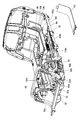
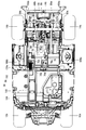
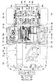
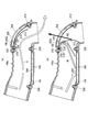
- FIG. 1 It is a top view which shows a frame part, a floor panel, etc.
- A is an enlarged view which shows an opening part
- (b) is an enlarged view which shows a plate-shaped member
- (c) is an enlarged view which shows a cover part.
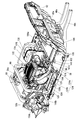
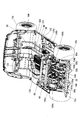
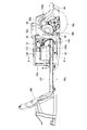
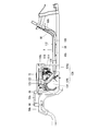
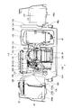
- It is a front perspective view which shows the principal part of a golf car. It is a front perspective view which shows the principal part of a golf car. It is a back perspective view showing the important section of a golf car.
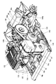
- FIG. 16 is a partial cross-sectional front view showing the engine, the muffler, and the vicinity thereof, cut along the line AA in FIG. 15.
- FIG. 16 is a partial cross-sectional plan view showing the engine, the muffler, and the vicinity thereof, which is cut along the line BB in FIG. 15.
- It is a top view which shows an engine, a muffler cover, and its vicinity.
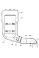
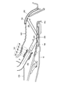
- FIG. 20 is a partial cross-sectional side view showing a muffler, a muffler cover, an exhaust duct, and the vicinity thereof, which is cut along line CC in FIG. 19. It is a partial cross section side view which shows a muffler, a muffler cover, and an exhaust duct. It is a cross-sectional solution figure which shows an exhaust duct and its vicinity. It is sectional drawing solution which shows the principal part of embodiment which provided the opening-and-closing member and the cooling hole. It is a figure which shows the opening / closing member, holding member, etc. which were seen from the arrow D direction (refer FIG.
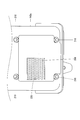
- FIG. 26 is a diagram showing an exhaust duct, an opening / closing member, a holding member, and the like viewed from the direction of arrow E (see FIG. 25) in a state where the opening / closing member is closed. It is a figure which shows the exhaust duct, the cooling hole, the holding member, etc. which were seen from the arrow F direction (refer FIG. 25).
- A) is an illustration figure which shows the flow of the exhaust gas in the state where the opening-and-closing member was opened
- (b) is an illustration figure which shows the change of the sound pressure and the exhaust heat direction in the state where the opening-and-closing member is closed.
- front and rear, left and right, and top and bottom mean front and rear, left and right, and top and bottom with respect to a state where the driver is seated on the seat portion 18 of the golf car 10 toward the steering wheel 30.
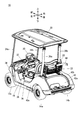
- golf car 10 is a two-seater golf car, and includes a pair of front wheels 12a and 12b (see FIG. 9), a pair of rear wheels 14a and 14b, and a frame portion 16.
- the pair of rear wheels 14a, 14b is provided behind the pair of front wheels 12a, 12b.
- the pair of front wheels 12 a and 12 b are rotatably supported on the front portion of the frame portion 16, and the pair of rear wheels 14 a and 14 b are rotatably supported on the rear portion of the frame portion 16.
- a seat portion 18 is provided so as to extend in the width direction of the golf car 10 behind the pair of front wheels 12a and 12b and ahead of the pair of rear wheels 14a and 14b.
- the seat portion 18 is supported by a seat rail 72 (described later) of the frame portion 16.
- a backrest 20 is provided obliquely above and rearward of the seat portion 18.
- a car 22 for accommodating luggage is provided behind the backrest 20.
- the backrest 20 and the car 22 are supported by rear pillars 26a and 26b described later.
- a pair of front pillars 24 a and 24 b are provided in front of the seat portion 18, and a pair of rear pillars 26 a and 26 b are provided in the rear of the seat portion 18.
- the lower end portions of the front pillars 24 a and 24 b and the lower end portions of the rear pillars 26 a and 26 b are supported by the frame portion 16.
- the front pillars 24a and 24b and the rear pillars 26a and 26b extend from the bottom to the top so as to be inclined slightly rearward.
- the roof portion 28 covering the upper portion of the seat portion 18 is supported by the front pillars 24a and 24b and the rear pillars 26a and 26b.
- a steering wheel 30 is provided in front of the backrest 20.
- the steering wheel 30 is coupled to the front wheels 12a and 12b via a steering shaft 32 and a coupling mechanism (not shown).
- a cowl 34 made of, for example, a pair of side protectors 36, a floor panel 38, a body panel 39, a pair of rear fender covers 40a and 40b, and a rear floor cover 42 are provided so as to cover the frame portion 16, respectively.
- the cowl 34 covers the front portion of the frame portion 16 and the front wheels 12a and 12b.
- the pair of side protectors 36 covers the central portion of the frame portion 16 from both sides.
- the floor panel 38 functions as a footrest on which a driver and a passenger sitting on the seat portion 18 can put his / her feet, and constitutes a bottom portion of the cabin space of the golf car 10.
- the body panel 39 covers the front side below the seat portion 18.
- the pair of rear fender covers 40a and 40b cover both sides below the seat portion 18 and above the pair of rear wheels 14a and 14b.
- the rear floor cover 42 is provided so as to be sandwiched between the rear ends of the pair of rear fender covers 40a and 40b, and has, for example, a recess 42a for placing a golf bag.
- Maintenance of the CVT (continuously variable transmission) 144 (described later) and the transmission 146 (described later) can be easily performed simply by removing the rear floor cover 42.
- a holding portion 44 for holding the golf bag is provided above the recess 42 a and behind the car 22.
- the holding part 44 is supported by connecting members 70a and 70b (described later).
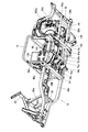
- the frame portion 16 includes a pair of main frames 46a and 46b, cross members 52, 54, 56, and 58 that extend in the vehicle front-rear direction and are spaced apart from each other in the vehicle width direction.
- Each of the pair of main frames 46a and 46b includes front frames 48a and 48b extending in the front-rear direction, and rear frames 50a and 50b extending rearward from the rear ends of the front frames 48a and 48b.
- the pair of front frames 48a and 48b are formed such that the interval between the front end portions is narrower than the interval between the rear end portions.
- the pair of rear frames 50a and 50b are formed to be curved so as to protrude upward.
- the front frames 48a and 48b are connected by cross members 52 and 54.
- a connecting portion of the front frame 48a and the rear frame 50a and a connecting portion of the front frame 48b and the rear frame 50b are connected by a cross member 56.
- the rear ends of the rear frames 50a and 50b are connected by a cross member 58. That is, the main frames 46a, 46b are connected by the cross members 52, 54, 56, 58 extending in the vehicle width direction.
- the cross members 52, 54, 56, and 58 are arranged in this order from the front to the rear of the vehicle with a space therebetween in the longitudinal direction of the vehicle.
- a pair of support frames 60a and 60b extending obliquely forward are connected to the cross member 52.
- the cross member 62 extending in the vehicle width direction is supported by the front end portions of the pair of support frames 60a and 60b.
- a pair of support frames 64a and 64b extending upward are connected to the vicinity of the cross member 54 in the pair of front frames 48a and 48b.
- the front portions of the pair of rear frames 50 a and 50 b are connected by a connecting frame 66.
- Center portions of the pair of rear frames 50 a and 50 b are connected by a connecting frame 68.
- the connecting frame 66 is formed in a substantially U shape that protrudes upward so as to extend in the vehicle width direction and both ends extend downward.
- the connecting frame 68 is formed in a substantially U shape that protrudes upward so as to extend in the vehicle width direction and both ends extend downward.
- connection frames 66 and 68 are provided at intervals in the vehicle front-rear direction, and are connected by connection members 70a and 70b. Further, the upper end portions of the pair of support frames 64 a and 64 b and both side portions of the connection frame 66 are connected by the seat rail 72.
- the seat rail 72 is formed in a substantially C shape extending in the horizontal direction.
- a pair of brackets 74a and 74b are attached to the cross member 54 so as to be aligned in the vehicle width direction.
- a pair of engine brackets 76a and 76b are connected to the pair of brackets 74a and 74b.
- the engine brackets 76 a and 76 b are connected via a cross member 78.
- a support frame 79 extending forward and support frames 80a and 80b extending rearward are connected to the cross member 78.
- a protrusion 79 a is formed at the tip of the support frame 79.
- Through holes 82a and 82b are formed at the rear ends of the support frames 80a and 80b, respectively (see FIG. 8).
- An engine bracket 84 that supports an engine 114 (described later) is attached to the cross member 78 and the support frames 80a and 80b.
- the cross member 78 is connected to the engine brackets 76a and 76b so as to be swingable in the vertical direction, and the engine bracket 84 is also swingable in the vertical direction accordingly.
- the cross member 56 is connected to a pair of frames 86a and 86b extending rearward. The vicinity of the rear ends of the pair of frames 86 a and 86 b is connected by a cross member 88. The rear ends of the pair of frames 86 a and 86 b are connected to the cross member 58.
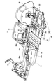
- the under cover 90 is supported by the frame portion 16.
- the under cover 90 has a front cover portion 92 and a rear cover portion 94 that are positioned in the front-rear direction.
- the front cover portion 92 is provided between the cross members 54 and 56 and is attached to the pair of front frames 48 a and 48 b and the cross members 54 and 56.
- the rear cover portion 94 is provided between the cross members 56 and 58, and is attached to the cross members 56 and 88, the frames 86a and 86b, and the rear frames 50a and 50b.
- a pair of inner cowls 95 (the right inner cowl is not shown) are attached to the rear frames 50a and 50b, respectively.
- the pair of inner cowls 95 are provided between the rear wheels 14a and 14b and the rear fender covers 40a and 40b so as to cover the upper portions of the rear wheels 14a and 14b, respectively.
- the space defined by the under cover 90, the seat portion 18, the body panel 39, the heat shield 176 (described later), the fuel tank 168 (described later), the left and right inner cowls 95, and the rear floor cover 42 serves as the engine room S.
- the engine room S is surrounded by the under cover 90, the seat portion 18, the body panel 39, the heat shield 176, the fuel tank 168, the left and right inner cowls 95, and the rear floor cover 42.
- the under cover 90 On the lower side, upper side, front side, left side, right side, and rear side of the engine room S, the under cover 90, the seat portion 18, the body panel 39, the heat shield plate 176, the left inner cowl 95, the fuel tank 168, and A right inner cowl 95 and a rear floor cover 42 are provided.
- the under cover 90 is provided below the engine 114 and defines the lower side of the engine room S. As described above, the engine room S is surrounded by the under cover 90, the seat portion 18, the body panel 39, the heat shield plate 176, the fuel tank 168, the left and right inner cowls 95, and the rear floor cover 42. It is possible to suppress leakage to the outside of S.
- the floor panel 38 is provided on the front frames 48 a and 48 b and the cross member 62 of the frame portion 16.
- the floor panel 38 is provided between the pair of front wheels 12a and 12b and the pair of rear wheels 14a and 14b.
- Floor panel 38 includes a panel body 96, an opening 98, and a groove 100.
- the panel body 96 includes a first panel portion 102 that extends substantially horizontally in the front-rear direction between the front wheels 12a and 12b and the rear wheels 14a and 14b, and a rear end of the front wheels 12a and 12b and the front end of the first panel portion 102.
- a second panel portion 104 extending upward from the first portion, and third panel portions 106 a and 106 b extending rearward from the left and right rear ends of the first panel portion 102.
- the first panel portion 102 is located in front of the engine room S
- the third panel portion 106 a is located on the left side of the engine room S
- the third panel portion 106 b is located on the right side of the engine room S.
- the second panel unit 104 rises obliquely forward from the front end of the first panel unit 102.
- the opening 98 is provided in the front portion of the panel main body 96, that is, in the second panel portion 104 (see FIG. 10A). In FIG. 10A, the opening 98 is hatched.
- the groove 100 communicates with the opening 98 to supply outside air introduced from the opening 98 into a shroud 132 (described later) and into the engine 114, and extends in the front-rear direction of the panel body 96.
- the groove portion 100 is provided continuously from the second panel portion 104 to the first panel portion 102, communicates the opening 98 and the engine room S, and guides the traveling wind from the front of the golf car 10 to the engine room S. Can do.
- the groove part 100 is formed slightly to the right of the center in the vehicle width direction.
- the opening 98 is provided on the side surface 100 a of the groove 100. Referring to FIGS.
- a plate-like member 108 protruding forward from the back surface (front surface) of the second panel portion 104 is provided on the side of the opening 98.
- a square plate-like cover part 110 supported by the frame part 16 is provided in front of the opening part 98.
- the groove part 100 is covered with the cover part 112 (refer FIG. 8).
- the lid portion 112 is made of a strip-like plate-like member, and is formed according to the shape of the groove portion 100 in the longitudinal direction.
- the engine 114 is supported by the engine bracket 84 in the engine room S.
- the engine 114 is an air-cooled single cylinder engine, for example.
- the engine 114 is provided with a fuel injection device 115 that injects fuel into the intake pipe 126.
- the engine 114 is provided behind the first panel portion 102 of the floor panel 38 and includes a cylinder head 116, a cylinder body 118, and a crankcase 120.
- the engine 114 is provided to incline forward.
- An air cleaner 122 is provided above the engine 114.
- An air intake duct 124 is connected to the air cleaner 122 via a joint 123.
- the intake duct 124 is provided on the right side of the air cleaner 122 and includes a cylindrical front duct 124a and a flat rear duct 124b having a noise reduction effect.
- the rear end portion of the front duct 124a and the front end portion of the rear duct 124b are connected.
- the front duct 124 a is disposed so as to face the groove 100 from the engine room S in order to introduce outside air from the groove 100, and the rear end portion of the rear duct 124 b is connected to the joint 123. In this way, the intake duct 124 and the air cleaner 122 are communicated with each other. As indicated by an arrow X in FIG.
- the outside air introduced from the front through the opening 98 into the groove 100 is introduced from the groove 100 into the air cleaner 122 through the intake duct 124.
- the air purified by the air cleaner 122 is supplied into the engine 114 through the intake pipe 126.
- the air cleaner 122 is provided between the intake duct 124 and the engine 114.
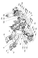
- a muffler 128 is provided adjacent to the side of the engine 114 (to the left in this embodiment).
- the engine 114 and the muffler 128 are connected via an exhaust pipe 130, and the exhaust from the engine 114 is given to the muffler 128 via the exhaust pipe 130.
- the cylinder body 118 of the engine 114 is covered with the shroud 132 so as to form a gap through which air can flow between the cylinder body 118 and the shroud 132.
- a fan case 134 is provided on the side surface of the engine 114 (in this embodiment, the right side surface), and the shroud 132 and the fan case 134 are continuously provided.
- a fan 136 for supplying outside air from the groove portion 100 into the shroud 132 (between the shroud 132 and the engine 114) is accommodated in the fan case 134.
- Fan 136 is preferably coupled to and driven by crankshaft 142 (see FIG. 18).
- the muffler 128 is covered by the muffler cover 138 so as to form a gap through which air can flow between the muffler 128 and the muffler cover 138.
- the shroud 132 and the muffler cover 138 are communicated by a duct 139 that covers the exhaust pipe 130. Note that the duct 139 is not shown in FIGS. 11, 12, 20, and 21.
- An exhaust duct 140 is connected to the outlet side end portion of the muffler cover 138, and the rear end portion of the exhaust duct 140 faces the outside from the opening 92a of the front cover portion 92 (FIGS. 7, 20, and 22). reference).
- the muffler cover 138 is supported by the support frame 79 by inserting the protrusions 79a of the support frame 79 into the holes 141a of the bracket 141 attached to the side surface thereof (see FIGS. 4 and 11). As shown by an arrow Y in FIGS. 17 and 18, the outside air supplied into the shroud 132 by the fan 136 passes between the shroud 132 and the engine 114 (cylinder body 118) and enters the muffler cover 138 (muffler cover). 138 and the muffler 128), and functions as cooling air for cooling the engine 114 and the muffler 128.
- the air in the muffler cover 138 passes through the exhaust duct 140 and is discharged from the opening 92 a of the front cover portion 92 to the lower outside of the engine room S.
- the muffler 128, the muffler cover 138, the exhaust duct 140, and the vicinity thereof will be described later.
- the output from the crankshaft 142 of the engine 114 is transmitted to the transmission 146 via a CVT (continuously variable transmission) 144.
- the CVT 144 is provided behind the muffler 128, and the transmission 146 is provided behind the engine 114 and between the pair of rear wheels 14a and 14b.
- the engine 114, the muffler 128, the shroud 132, the muffler cover 138, the exhaust duct 140, the CVT 144, and the transmission 146 described above are accommodated in the engine room S.
- the transmission 146 is connected to a pair of rotation transmission units 148a and 148b.
- the rotation transmission unit 148a extends to the left of the transmission 146 and includes a constant velocity joint 150a, a drive shaft 152a, a constant velocity joint 154a, and an axle 156a.
- An output shaft (not shown) of transmission 146 and drive shaft 152a are connected by constant velocity joint 150a, and drive shaft 152a and axle 156a are connected by constant velocity joint 154a.
- the rotation transmission unit 148b extends to the right of the transmission 146 and includes a constant velocity joint 150b, a drive shaft 152b, a constant velocity joint 154b, and an axle 156b.
- the output shaft of the transmission 146 and the drive shaft 152b are connected by a constant velocity joint 150b, and the drive shaft 152b and the axle 156b are connected by a constant velocity joint 154b.
- the axle 156a supports the rear wheel 14a, and the axle 156b supports the rear wheel 14b.
- the through hole 82a at the rear end portion of the support frame 80a is inserted through the output shaft of the transmission 146 between the transmission 146 and the constant velocity joint 150a, and the through hole 82b at the rear end portion of the support frame 80b is inserted into the transmission 146.
- the constant velocity joint 150b are inserted through the output shaft of the transmission 146 (see FIG. 13).
- the pair of rear wheels 14a and 14b are suspended by a pair of suspensions 158a and 158b.
- the pair of suspensions 158a and 158b are independent suspensions.
- the pair of suspensions 158a and 158b include knuckle 160a and 160b, arms 162a and 162b, and shock absorbers 164a and 164b, respectively.
- the knuckle 160a supports the axle 156a in a rotatable manner.
- the arm 162a connects the lower part of the knuckle 160a and the frame 86a.
- the lower end and the upper end of the shock absorber 164a are connected to the upper end of the knuckle 160a and the connecting frame 68, respectively.
- the knuckle 160b rotatably supports the axle 156b.
- the arm 162b connects the lower part of the knuckle 160b and the frame 86b.
- the lower end and upper end of the shock absorber 164b are connected to the upper end of the knuckle 160b and the connecting frame 68, respectively.
- the pair of front wheels 12a and 12b are suspended by a pair of suspensions 166a and 166b attached to the front portion of the frame portion 16.
- the pair of suspensions 166a and 166b are independent suspensions.
- a fuel tank 168 is provided on the right side of the engine 114 and on the third panel portion 106b of the floor panel 38.
- a sound absorbing material 170 is attached so as to stand.
- a battery 172 is provided on the left side of the muffler cover 138 and on the third panel portion 106 a of the floor panel 38. Between the muffler cover 138 and the battery 172, a sound absorbing material 174 and a heat shield plate 176 are arranged so as to overlap and stand up. Noise from the engine room S can be absorbed by the sound absorbing materials 170 and 174, and heat from the engine room S can be prevented from reaching the battery 172 by the heat shield plate 176.
- the muffler 128, the muffler cover 138, the exhaust duct 140, and the vicinity thereof will be described with reference to FIGS.
- the muffler 128 has an expansion chamber 178 filled with a sound absorbing member such as glass wool at the rear part thereof.
- the expansion chamber 178 reduces exhaust noise.
- the expansion chamber 178 is provided with a discharge pipe 180 so as to extend rearward and obliquely downward. That is, the exhaust pipe 180 is provided at the exhaust port of the muffler 128 (exhaust outlet).
- a joint exhaust 182 is attached to the rear end of the discharge pipe 180.
- the joint exhaust 182 includes a silencer 184, a seal member 186, a holding member 188, a cap member 190, and a fastening member 192.
- the silencer 184 is made of, for example, a stainless steel mesh member, and is provided at the exhaust port of the muffler 128 via the exhaust pipe 180 to suppress exhaust momentum and change the sound quality of the exhaust sound.
- the seal member 186 is formed in a hollow cylindrical shape and is fitted on the outer periphery of the rear end portion of the discharge pipe 180.
- the cylindrical holding member 188 and the annular cap member 190 are integrally formed and hold the silencer 184 and the seal member 186.
- the fastening member 192 is fitted on the outer peripheral surface of the holding member 188 and tightens the holding member 188 so that the holding member 188 presses the silencer 184 and the seal member 186 radially inward.
- the muffler cover 138 is made of, for example, resin, and a heat insulating material (not shown) is provided on the inner surface, and the upper part is formed in a substantially rectangular tube shape and the lower part is formed in a substantially cylindrical shape (see FIGS. 20 and 21).
- the exhaust duct 140 is made of, for example, rubber, has flexibility, and is formed in a flat shape (see FIGS. 20 and 21).
- the exhaust duct 140 extends rearward through the upper portion of the under cover 90 (front cover portion 92) in order to exhaust the exhaust from the lower side of the engine room S to the outside, and the rear end portion of the exhaust duct 140 is the rear cover portion of the front cover portion 92. It is located in the opening 92a and is fitted into the opening 92a.
- the opening 92a is located behind the muffler 128 in a side view. Further, the opening 92a is located behind the muffler cover 138 in a side view.
- the exhaust duct 140 has recesses 196 and 198 in the lower portion and the upper portion of the inner peripheral surface thereof, respectively.
- portions corresponding to the recesses 196 and 198 protrude outward in a square shape (see FIGS. 6 and 21).
- the sound absorbing members 200 and 202 are fitted in the recesses 196 and 198, respectively.
- the sound absorbing member 200 is formed on the extension line of the central axis P of the exhaust pipe 180 provided at the exhaust port of the muffler 128 on the inner peripheral surface of the exhaust duct 140, and the sound absorbing member 202 is reflected by the sound absorbing member 200. It is formed at the location where the exhaust is hit.
- the sound absorbing members 200 and 202 are preferably glass wool.
- holding members 204 and 206 are attached to the inner peripheral surface of the exhaust duct 140.
- the holding members 204 and 206 are provided so as to cover the sound absorbing members 200 and 202, and are attached by fastening members 208 and 210, respectively.
- the holding members 204 and 206 are preferably perforated plates.
- the perforated plate is a plate-like member having a large number of through holes.
- the holding members 204 and 206 are punching metal. As shown in FIG.
- the exhaust sound discharged from the exhaust pipe 180 of the muffler 128 into the exhaust duct 140 is reflected by the sound absorbing members 200 and 202 as indicated by white arrows to absorb the sound.
- the thickness of the white arrow indicates the sound pressure, and the exhaust sound gradually attenuates.
- the exhaust duct 140 connected to the outlet side end portion of the muffler cover 138 extends rearward through the upper portion of the under cover 90 provided below the engine 114, and the exhaust duct 140.
- the rear end portion is located in the opening 92a located behind the muffler 128 in a side view.
- Exhaust gas from the muffler 128 is discharged to the outside from below the engine room S via the exhaust duct 140 and the opening 92a of the under cover 90 (front cover portion 92).
- the exhaust duct 140 extends rearward so that the rear end portion of the exhaust duct 140 is located behind the muffler 128, the sound from the muffler 128 is attenuated in the exhaust duct 140.
- the exhaust duct 140 is connected to the muffler cover 138, the cooling air from the muffler cover 138 is discharged from the opening 92a through the exhaust duct 140, and the vibration noise of the engine 114 transmitted through the muffler cover 138, etc. Are attenuated in the exhaust duct 140. Therefore, it is possible to suppress sound from leaking outside the vehicle.
- the vertical movement of the muffler cover 138 can be absorbed, so that the rear end portion of the exhaust duct 140 can be stably positioned at the opening 92 a of the under cover 90.
- the sound from the muffler 128 can be further attenuated by the silencer 184, and sound leakage to the outside of the vehicle can be further suppressed.
- the sound absorbing members 200 and 202 can be reliably held on the inner peripheral surface of the exhaust duct 140 by the holding members 204 and 206.
- the sound absorbing members 200 and 202 can be reliably provided on the inner peripheral surface of the exhaust duct 140 while maintaining the sound absorbing function of the sound absorbing members 200 and 202.
- a sound absorbing material may be attached to the seat portion 18, the body panel 39, the rear floor cover 42, the under cover 90, and the left and right inner cowls 95.
- an exhaust duct 140a shown in FIG. 25 may be used instead of the exhaust duct 140, and an opening / closing member 212 may be provided in the exhaust duct 140a.
- the exhaust duct 140a is the same as the exhaust duct 140 except that it has a cooling hole 220 (described later).
- the opening / closing member 212 is configured to be open when the golf car 10 is running and to be closed when the golf car 10 is stopped.
- the opening / closing member 212 is configured to open by exhaust passing through the exhaust duct 140a and to close by the gravity (self-weight) of the opening / closing member 212.
- the opening degree (opening degree) of the opening / closing member 212 is set according to the exhaust pressure received by the opening / closing member 212. In FIG.
- the opening / closing member 212 is made of, for example, a slightly curved plate-shaped and stainless steel exhaust flap.
- the central portion in the width direction of one end (upper end) of the opening / closing member 212 is connected to the central portion in the width direction of one end (upper end) of the holding member 206 via a hinge 214 made of stainless steel, for example.
- the opening / closing member 212 and the hinge 214 are connected by a fastening member 216, and the holding member 206 and the hinge 214 are connected by a fastening member 218.
- the width of the opening / closing member 212 is set larger than the width of the holding member 206.
- the opening / closing member 212 can be opened / closed (swinged) with the hinge 214 as a fulcrum.
- the opening / closing member 212 is provided in the vicinity of the opening 92a where the rear end of the exhaust duct 140a is located.
- the exhaust duct 140a penetrates the inner peripheral surface and the outer peripheral surface (the upper surface corresponding to the recess 198 in this embodiment) in the vicinity of the downstream side of the closed open / close member 212.
- a cooling hole 220 is provided as described above.
- the cooling hole 220 is formed above the opening 92a where the rear end of the exhaust duct 140a is located.
- the sound absorbing member 202a is cut out at a portion corresponding to the cooling hole 220 and fitted into the recess 198 of the exhaust duct 140a. Therefore, the holding member 206 is exposed to the outside in the cooling hole 220.
- the opening / closing member 212 when the golf car 10 is traveling, the opening / closing member 212 is opened, so that the exhaust from the muffler 128 is exhausted from the exhaust duct 140a and the under cover 90 as shown by the white arrow G in FIG. Can be smoothly discharged from below the engine room S through the opening 92a.
- the opening / closing member 212 is closed, so that the sound from the muffler 128, the vibration sound of the engine 114 transmitted through the muffler cover 138, etc., as indicated by the white arrow H1 in FIG. Can be further attenuated in the exhaust duct 140a, and sound leakage outside the vehicle can be further suppressed.
- the thickness of the white arrow H1 indicates the sound pressure.
- the opening / closing member 212 is configured to open by exhaust passing through the exhaust duct 140a, the opening / closing member 212 can be opened without requiring a separate member for opening the opening / closing member 212.
- the opening / closing member 212 When the engine 114 is driven at a low rotational speed (for example, 2500 rpm or less), since the exhaust pressure (displacement amount) is small, the opening / closing member 212 is in a half-open state, and exhaust exhaust and suppression of sound leakage outside the vehicle are suppressed. Can be compatible. This is particularly effective when the golf car 10 travels at a constant speed.
- the opening / closing member 212 When the opening / closing member 212 is closed when the golf car 10 is stopped, the heat of the opening / closing member 212 is moved out of the exhaust duct 140a through the cooling hole 220 as shown by an arrow H2 in FIG. 29B (in this embodiment, upward). ) Since the opening / closing member 212 can be cooled by letting it escape, deterioration of the opening / closing member 212 due to heat can be suppressed.
- the opening / closing member 212 is configured to be closed by its own weight, but is not limited thereto.
- the opening / closing member 212 may be configured to be closed by an elastic member such as a spring.
- the present invention is not limited to this.
- the present invention can be applied to any other vehicle.
Landscapes
- Engineering & Computer Science (AREA)
- Chemical & Material Sciences (AREA)
- Combustion & Propulsion (AREA)
- Mechanical Engineering (AREA)
- General Engineering & Computer Science (AREA)
- Transportation (AREA)
- Body Structure For Vehicles (AREA)
- Cooling, Air Intake And Gas Exhaust, And Fuel Tank Arrangements In Propulsion Units (AREA)
Abstract
Description
90 アンダーカバー
92 前カバー部
92a,98 開口部
114 エンジン
118 シリンダボディ
128 マフラー
132 シュラウド
138 マフラーカバー
140,140a 排気ダクト
184 サイレンサ
200,202,202a 吸音部材
204,206 保持部材
212 開閉部材
220 冷却孔
S エンジンルーム
Claims (11)
- シリンダボディを有するエンジンと、
前記エンジンからの排気が供給されるマフラーと、
前記シリンダボディを覆うシュラウドと、
前記マフラーを覆いかつ前記シュラウドに連通するマフラーカバーと、
前記エンジンより下方に設けられかつ開口部を有するアンダーカバーと、
前記マフラーカバーの出口側端部に連設される排気ダクトと、
前記アンダーカバーによって下側が規定されかつ前記エンジン、前記マフラー、前記シュラウド、前記マフラーカバーおよび前記排気ダクトを収容するエンジンルームとを備え、
前記開口部は、側面視において前記マフラーよりも後方に位置し、
前記排気を前記エンジンルームの下方から外部に排出するために前記排気ダクトは前記アンダーカバーの上方を通りかつ前記排気ダクトの後端部は前記開口部に位置する、車両。 - 前記排気ダクトは可撓性を有する、請求項1に記載の車両。
- 前記排気ダクトは前記開口部に嵌められる、請求項1または2に記載の車両。
- 前記マフラーの排出口に設けられるサイレンサをさらに含む、請求項1から3のいずれかに記載の車両。
- 前記排気ダクトの内周面に設けられる吸音部材をさらに含む、請求項1から4のいずれかに記載の車両。
- 前記マフラーの排出口に設けられる排出管をさらに含み、
前記吸音部材は、前記排気ダクトにおいて前記排出管の中心軸の延長線上に形成される、請求項5に記載の車両。 - 前記吸音部材を前記排気ダクトの内周面に保持するための保持部材をさらに含み、前記保持部材は多孔板である、請求項5または6に記載の車両。
- 前記排気ダクト内に設けられる開閉部材をさらに含み、
前記開閉部材は、当該車両の走行時に開きかつ当該車両の停止時に閉じることが可能に構成される、請求項1に記載の車両。 - 前記開閉部材は、前記排気ダクト内を通る排気によって開くように構成される、請求項8に記載の車両。
- 前記開閉部材の開度は、前記開閉部材が受ける排気圧に応じて設定される、請求項9に記載の車両。
- 前記排気ダクトにおける閉状態の前記開閉部材よりも下流側の近傍において前記排気ダクトの内周面と外周面とを貫通するように設けられる冷却孔をさらに含む、請求項8から10のいずれかに記載の車両。
Priority Applications (4)
| Application Number | Priority Date | Filing Date | Title |
|---|---|---|---|
| US16/092,370 US10406911B2 (en) | 2016-07-08 | 2017-06-23 | Vehicle |
| CA3020819A CA3020819C (en) | 2016-07-08 | 2017-06-23 | Vehicle |
| EP17824039.6A EP3482990B1 (en) | 2016-07-08 | 2017-06-23 | Vehicle |
| AU2017292285A AU2017292285B2 (en) | 2016-07-08 | 2017-06-23 | Vehicle |
Applications Claiming Priority (4)
| Application Number | Priority Date | Filing Date | Title |
|---|---|---|---|
| JP2016-136457 | 2016-07-08 | ||
| JP2016136457 | 2016-07-08 | ||
| JP2017-108116 | 2017-05-31 | ||
| JP2017108116A JP6338739B2 (ja) | 2016-07-08 | 2017-05-31 | 車両 |
Publications (1)
| Publication Number | Publication Date |
|---|---|
| WO2018008432A1 true WO2018008432A1 (ja) | 2018-01-11 |
Family
ID=60912631
Family Applications (1)
| Application Number | Title | Priority Date | Filing Date |
|---|---|---|---|
| PCT/JP2017/023184 Ceased WO2018008432A1 (ja) | 2016-07-08 | 2017-06-23 | 車両 |
Country Status (2)
| Country | Link |
|---|---|
| EP (1) | EP3482990B1 (ja) |
| WO (1) | WO2018008432A1 (ja) |
Cited By (1)
| Publication number | Priority date | Publication date | Assignee | Title |
|---|---|---|---|---|
| CN115434797A (zh) * | 2022-09-26 | 2022-12-06 | 无锡宝顺不锈钢有限公司 | 一种用于汽车排气系统的不锈钢带 |
Citations (3)
| Publication number | Priority date | Publication date | Assignee | Title |
|---|---|---|---|---|
| JP2005007995A (ja) | 2003-06-18 | 2005-01-13 | Yamaha Motor Co Ltd | 小型車両 |
| JP2015210897A (ja) * | 2014-04-24 | 2015-11-24 | 本田技研工業株式会社 | 希釈器 |
| JP2016185749A (ja) * | 2015-03-27 | 2016-10-27 | 愛三工業株式会社 | 車両用エンジンの吸気装置 |
Family Cites Families (4)
| Publication number | Priority date | Publication date | Assignee | Title |
|---|---|---|---|---|
| JPH07215074A (ja) * | 1994-02-07 | 1995-08-15 | Toyota Motor Corp | 車両用アンダーカバー装置 |
| JP3414518B2 (ja) * | 1994-09-21 | 2003-06-09 | 本田技研工業株式会社 | 車両のエンジンルームの冷却構造 |
| JP5733335B2 (ja) * | 2013-04-19 | 2015-06-10 | コベルコ建機株式会社 | 建設機械の排気構造 |
| JP2016008599A (ja) * | 2014-06-26 | 2016-01-18 | ヤマハ発動機株式会社 | マフラーユニットおよびそれを備えた車両 |
-
2017
- 2017-06-23 EP EP17824039.6A patent/EP3482990B1/en active Active
- 2017-06-23 WO PCT/JP2017/023184 patent/WO2018008432A1/ja not_active Ceased
Patent Citations (3)
| Publication number | Priority date | Publication date | Assignee | Title |
|---|---|---|---|---|
| JP2005007995A (ja) | 2003-06-18 | 2005-01-13 | Yamaha Motor Co Ltd | 小型車両 |
| JP2015210897A (ja) * | 2014-04-24 | 2015-11-24 | 本田技研工業株式会社 | 希釈器 |
| JP2016185749A (ja) * | 2015-03-27 | 2016-10-27 | 愛三工業株式会社 | 車両用エンジンの吸気装置 |
Non-Patent Citations (1)
| Title |
|---|
| See also references of EP3482990A4 |
Cited By (2)
| Publication number | Priority date | Publication date | Assignee | Title |
|---|---|---|---|---|
| CN115434797A (zh) * | 2022-09-26 | 2022-12-06 | 无锡宝顺不锈钢有限公司 | 一种用于汽车排气系统的不锈钢带 |
| CN115434797B (zh) * | 2022-09-26 | 2024-03-26 | 无锡宝顺不锈钢有限公司 | 一种用于汽车排气系统的不锈钢带 |
Also Published As
| Publication number | Publication date |
|---|---|
| EP3482990B1 (en) | 2022-05-04 |
| EP3482990A1 (en) | 2019-05-15 |
| EP3482990A4 (en) | 2020-03-11 |
Similar Documents
| Publication | Publication Date | Title |
|---|---|---|
| JP6338739B2 (ja) | 車両 | |
| US8042649B2 (en) | Vehicular muffler and motorcycle incorporating same | |
| JP4826612B2 (ja) | 車両の排気浄化装置配設構造 | |
| CN101793187B (zh) | 跨骑型车辆的消音器罩 | |
| JP4924352B2 (ja) | 車両の排気浄化装置配設構造 | |
| US10406903B2 (en) | Vehicle | |
| JP6276334B2 (ja) | 車両 | |
| CN101712348A (zh) | 机动二轮车的滤罐安装结构 | |
| KR100811368B1 (ko) | 요동 삼륜차 | |
| JP5581847B2 (ja) | 自動二輪車のキャニスタ配置構造 | |
| CN103129662B (zh) | 踏板车型摩托车 | |
| EP3482990B1 (en) | Vehicle | |
| JPWO2012011468A1 (ja) | スクータ型自動二輪車 | |
| JP5778947B2 (ja) | 鞍乗り型車両の排気浄化装置 | |
| JP5581843B2 (ja) | 自動二輪車のキャニスタ配置構造 | |
| JP6586987B2 (ja) | 燃料電池ユニット | |
| JP7347155B2 (ja) | エンジンの吸気マニホールド | |
| JP6551000B2 (ja) | 燃料電池自動二輪車 | |
| JP4462573B2 (ja) | バーチカルエンジン搭載作業車の冷却機構 | |
| JP2012046110A (ja) | ベルト式自動変速機の冷却構造 |
Legal Events
| Date | Code | Title | Description |
|---|---|---|---|
| ENP | Entry into the national phase |
Ref document number: 3020819 Country of ref document: CA |
|
| ENP | Entry into the national phase |
Ref document number: 2017292285 Country of ref document: AU Date of ref document: 20170623 Kind code of ref document: A |
|
| 121 | Ep: the epo has been informed by wipo that ep was designated in this application |
Ref document number: 17824039 Country of ref document: EP Kind code of ref document: A1 |
|
| NENP | Non-entry into the national phase |
Ref country code: DE |
|
| ENP | Entry into the national phase |
Ref document number: 2017824039 Country of ref document: EP Effective date: 20190208 |