WO2018012245A1 - 加熱調理器 - Google Patents
加熱調理器 Download PDFInfo
- Publication number
- WO2018012245A1 WO2018012245A1 PCT/JP2017/023118 JP2017023118W WO2018012245A1 WO 2018012245 A1 WO2018012245 A1 WO 2018012245A1 JP 2017023118 W JP2017023118 W JP 2017023118W WO 2018012245 A1 WO2018012245 A1 WO 2018012245A1
- Authority
- WO
- WIPO (PCT)
- Prior art keywords
- heating
- unit
- image
- food
- control information
- Prior art date
- Legal status (The legal status is an assumption and is not a legal conclusion. Google has not performed a legal analysis and makes no representation as to the accuracy of the status listed.)
- Ceased
Links
Images



Classifications
-
- F—MECHANICAL ENGINEERING; LIGHTING; HEATING; WEAPONS; BLASTING
- F24—HEATING; RANGES; VENTILATING
- F24C—DOMESTIC STOVES OR RANGES ; DETAILS OF DOMESTIC STOVES OR RANGES, OF GENERAL APPLICATION
- F24C7/00—Stoves or ranges heated by electric energy
- F24C7/08—Arrangement or mounting of control or safety devices
- F24C7/082—Arrangement or mounting of control or safety devices on ranges, e.g. control panels, illumination
- F24C7/085—Arrangement or mounting of control or safety devices on ranges, e.g. control panels, illumination on baking ovens
-
- F—MECHANICAL ENGINEERING; LIGHTING; HEATING; WEAPONS; BLASTING
- F24—HEATING; RANGES; VENTILATING
- F24C—DOMESTIC STOVES OR RANGES ; DETAILS OF DOMESTIC STOVES OR RANGES, OF GENERAL APPLICATION
- F24C15/00—Details
-
- F—MECHANICAL ENGINEERING; LIGHTING; HEATING; WEAPONS; BLASTING
- F24—HEATING; RANGES; VENTILATING
- F24C—DOMESTIC STOVES OR RANGES ; DETAILS OF DOMESTIC STOVES OR RANGES, OF GENERAL APPLICATION
- F24C7/00—Stoves or ranges heated by electric energy
- F24C7/02—Stoves or ranges heated by electric energy using microwaves
-
- G—PHYSICS
- G06—COMPUTING OR CALCULATING; COUNTING
- G06K—GRAPHICAL DATA READING; PRESENTATION OF DATA; RECORD CARRIERS; HANDLING RECORD CARRIERS
- G06K7/00—Methods or arrangements for sensing record carriers, e.g. for reading patterns
- G06K7/10—Methods or arrangements for sensing record carriers, e.g. for reading patterns by electromagnetic radiation, e.g. optical sensing; by corpuscular radiation
- G06K7/14—Methods or arrangements for sensing record carriers, e.g. for reading patterns by electromagnetic radiation, e.g. optical sensing; by corpuscular radiation using light without selection of wavelength, e.g. sensing reflected white light
- G06K7/1404—Methods for optical code recognition
- G06K7/1408—Methods for optical code recognition the method being specifically adapted for the type of code
- G06K7/1413—1D bar codes
-
- H—ELECTRICITY
- H05—ELECTRIC TECHNIQUES NOT OTHERWISE PROVIDED FOR
- H05B—ELECTRIC HEATING; ELECTRIC LIGHT SOURCES NOT OTHERWISE PROVIDED FOR; CIRCUIT ARRANGEMENTS FOR ELECTRIC LIGHT SOURCES, IN GENERAL
- H05B6/00—Heating by electric, magnetic or electromagnetic fields
- H05B6/64—Heating using microwaves
- H05B6/6414—Aspects relating to the door of the microwave heating apparatus
-
- H—ELECTRICITY
- H05—ELECTRIC TECHNIQUES NOT OTHERWISE PROVIDED FOR
- H05B—ELECTRIC HEATING; ELECTRIC LIGHT SOURCES NOT OTHERWISE PROVIDED FOR; CIRCUIT ARRANGEMENTS FOR ELECTRIC LIGHT SOURCES, IN GENERAL
- H05B6/00—Heating by electric, magnetic or electromagnetic fields
- H05B6/64—Heating using microwaves
- H05B6/6435—Aspects relating to the user interface of the microwave heating apparatus
- H05B6/6441—Aspects relating to the user interface of the microwave heating apparatus allowing the input of coded operation instructions, e.g. bar code reader
-
- H—ELECTRICITY
- H05—ELECTRIC TECHNIQUES NOT OTHERWISE PROVIDED FOR
- H05B—ELECTRIC HEATING; ELECTRIC LIGHT SOURCES NOT OTHERWISE PROVIDED FOR; CIRCUIT ARRANGEMENTS FOR ELECTRIC LIGHT SOURCES, IN GENERAL
- H05B6/00—Heating by electric, magnetic or electromagnetic fields
- H05B6/64—Heating using microwaves
- H05B6/6447—Method of operation or details of the microwave heating apparatus related to the use of detectors or sensors
-
- H—ELECTRICITY
- H05—ELECTRIC TECHNIQUES NOT OTHERWISE PROVIDED FOR
- H05B—ELECTRIC HEATING; ELECTRIC LIGHT SOURCES NOT OTHERWISE PROVIDED FOR; CIRCUIT ARRANGEMENTS FOR ELECTRIC LIGHT SOURCES, IN GENERAL
- H05B6/00—Heating by electric, magnetic or electromagnetic fields
- H05B6/64—Heating using microwaves
- H05B6/66—Circuits
- H05B6/68—Circuits for monitoring or control
- H05B6/687—Circuits for monitoring or control for cooking
Definitions
- the present invention relates to a cooking device that heats food.
- a microwave oven which is a typical cooking device, has the convenience of heating food in a container without using a pan or frying pan. Then, in a store that sells lunch boxes or prepared dishes in containers, a service is provided in which the clerk heats and provides the purchased food using a microwave oven.
- the optimal heating time for heating in a microwave oven is displayed on a lunch box or a side dish container. And the salesclerk of a store sees the display, sets a heating time with a microwave oven, and heats.
- the operation part of the microwave oven is provided with numeric keys, etc., and the heating time (minutes and seconds) is set manually.
- the microwave oven has a plurality of operation buttons, and each operation button may be assigned a different heating time.
- the store clerk can select the button corresponding to the food to be heated, thereby heating the food with the heating control suitable for the food and providing the customer with the food.
- the heating time minutes, seconds
- the number of operations may be large, which may be a troublesome operation.
- the latter configuration that is, when different heating times are assigned to each of the plurality of operation buttons, it may be difficult to learn the correspondence with the buttons as the types of food increase. There is.
- the microwave oven stores the details of the heating control for each product in advance, and the store clerk uses the barcode reader to attach the barcode information attached to the product (A method is also proposed in which the microwave oven reads the heating control content corresponding to the product from the code information and performs appropriate heating.
- the microwave oven is equipped with a camera that captures the inside of the warehouse, and by extracting the barcode part from the image of the product put in the warehouse and reading the barcode,
- a method of performing appropriate heating by calling the heating control content corresponding to the product from the code information (see, for example, Patent Document 1).
- the microwave oven needs to store the heating control information for each product in advance. Absent.
- a very high-definition camera is required to read code information from images stored in the storage room of the microwave oven.
- code information there are white parts and black parts like barcodes, and in order to distinguish them clearly, there is no resolution to allocate several pixels for each black line segment and white interval. Cannot be read. This is the same whether it is a bar code or code information such as letters / numbers or other symbols.
- the present invention recognizes the heating control information with a simple configuration including one camera, and automatically sets the heating control content.
- the heating cooker of the present invention includes a heating chamber in which an object to be heated is stored, a heating unit that heats the object to be heated placed in the heating chamber, an imaging unit that images the inside of the heating chamber, and an imaging unit.
- a heating control information recognition unit for recognizing the heating control information of the object to be heated from the obtained image.
- a heating control unit that controls the heating unit based on the heating control information recognized by the heating control information recognition unit, and a placement position guide unit that guides the placement position of the object to be heated to the imaging range of the imaging unit.
- the placement position guiding unit is the imaging unit. Therefore, the heating control information can be recognized with a simple configuration including one camera.
- FIG. 1 is an external perspective view of a heating cooker according to the first embodiment of the present invention.
- FIG. 2 is a schematic configuration diagram of the heating cooker according to the first embodiment of the present invention.
- FIG. 3 is an explanatory diagram of product information including heating control information displayed on an object to be heated that is heated by the heating cooker according to the first embodiment of the present invention.
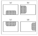
- FIG. 4 is a comparison result image of the image comparison unit of the heating cooker according to the first embodiment of the present invention, and is an explanatory diagram of a difference image when one side of the object to be heated is in contact with the periphery.
- FIG. 1 is an external perspective view of a heating cooker according to the first embodiment of the present invention.
- FIG. 2 is a schematic configuration diagram of the heating cooker according to the first embodiment of the present invention.
- FIG. 3 is an explanatory diagram of product information including heating control information displayed on an object to be heated that is heated by the heating cooker according to the first embodiment of the present invention.
- FIG. 4 is a comparison result image
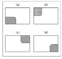
- FIG. 5 is a comparison result image of the image comparison unit of the heating cooker according to the first embodiment of the present invention, and is an explanatory diagram of a difference image when two sides of the object to be heated are in contact with the surroundings.
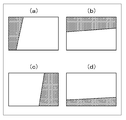
- FIG. 6 is a comparison result image of the image comparison unit of the heating cooker according to the first embodiment of the present invention, and is an explanatory diagram of the comparison result image when three sides of the object to be heated are in contact with the surroundings.
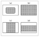
- FIG. 7 is an explanatory diagram of a difference image in the case where the induction direction of the object to be heated cannot be determined in the comparison result image of the image comparison unit of the heating cooker according to the first embodiment of the present invention.
- FIG. 8 is a flowchart showing a flow of operation when the door of the cooking device in the first embodiment of the present invention changes from the open state to the closed state.
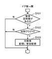
- FIG. 9 is a flowchart showing an operation flow when the door of the cooking device in the first embodiment of the present invention changes from the closed state to the open state.
- FIG. 1 is an external perspective view of a microwave oven as an example of a heating cooker according to the first embodiment of the present invention.
- the microwave oven 1 is provided with a door 3 for putting food in and out of a housing 2 for storing food.
- the door 3 is provided with a transparent glass window 4 for allowing the inside of the housing 2 to be seen from the outside, a handle 5 that is gripped when the door 3 is opened and closed, and an operation display unit 6.
- the operation display unit 6 includes a liquid crystal display 7, a time setting button group 8, a heating start button 9, a cancel button 10, and a pause button 11.
- the microwave oven 1 captures a food to be heated (object to be heated) with a photographing unit, reads a heating time displayed on the food, and heats the food with the heating time.
- the read heating time is displayed on the liquid crystal display 7 and information characters are displayed.
- the liquid crystal display 7 displays the guidance direction determined by a guidance direction determination unit 33 (see FIG. 2) described later.
- a time setting button group 8 is provided in the microwave oven 1 when the heating time cannot be read well, or when the food for which the heating time is not displayed is heated.
- the user can set the heating time using the numeric buttons and the “minute” and “second” buttons. In this case, the set heating time is displayed on the liquid crystal display 7.
- the heating start button 9 is a button that is pressed when the user starts heating after confirming the heating time displayed on the liquid crystal display 7.
- the cancel button 10 is pressed by the user when the user presses the heating start button 9 to start heating and then stops heating during heating, or the heating time displayed on the liquid crystal display 7 is set. This button is pressed by the user when canceling.
- the pause button 11 is a button that is pressed by the user when heating is temporarily stopped during heating. When heating is temporarily stopped, the user presses the heating start button 9 again to perform the remaining heating from the middle.
- FIG. 2 is a schematic configuration diagram of the microwave oven 1 according to the present embodiment.
- the microwave oven 1 can heat foods and the like with high frequencies, and includes a magnetron 13 that is a heating unit that outputs high frequencies in a heating chamber 12 that stores an object to be heated such as foods.
- the magnetron 13 supplies high frequency to the heating chamber 12 to heat the food.
- the magnetron 13 is controlled by the heating control unit 14.
- the microwave oven 1 includes an illumination 15 and a camera 16 as a photographing unit on the same side as the illumination 15 is provided.
- the camera 16 captures an image in the heating chamber 12. Since the camera 16 is arranged on the same side as the illumination 15, the inside of the heating cabinet 12 can be photographed without being backlit.
- the housing 2 is provided with a door switch 17 for detecting the opening / closing of the door 3.
- the door 3 includes a protrusion 18 for pushing in the door switch 17.
- the heating control information recognition unit 19 includes a reading unit 20, and the reading unit 20 extracts, from the image taken by the camera 16, a portion where the heating control information is displayed from the sticker attached to the product. Then, the characters (including at least numbers) of the heating control information are read.
- FIG. 3 shows an example of the seal 21 attached to the food.
- the seal 21 includes various items such as a product name 22, heating control information 23, money amount information 24, expiration date information 25, a barcode 26 that is an example of a code symbol that identifies food, nutrition information 27, and information 28. Information is displayed.
- the seal 21 has a mark frame 29 which is a rectangular position designation mark formed so as to surround the heating control information 23. It is displayed.
- the heating control information 23 of the seal 21 includes two types of heating control information. More specifically, the heating control information 23 of the seal 21 is a guideline for heating with a general household microwave oven, for example, the heating time when heating with a heating power of 500 W, and the electronic for business use. As a guideline for heating in a range with a large heating power for a short time, for example, the heating time in the case of heating with a heating power of 1500 W is also shown. For example, “500W 2:00 minutes 1500W 0 minutes 40 seconds” is displayed.
- the heating control information 23 is a character string including the first character string to the sixth character string in the order of the first character string, the second character string,.
- the first character string is a number representing the heating amount with a predetermined heating power, and is “500”, for example.
- the second character string represents the unit of the heating power, for example “W”.
- the third character string is a number that is a heating time at the heating power, and is “2”, for example.
- the fourth character string represents the unit of the heating time, for example, “minute”.
- the fifth character string is a number indicating the heating time with the heating power, and is, for example, “00”.
- the sixth character string represents the unit of the heating time, for example, “second”.
- the heating control information is a character string including the seventh character string to the twelfth character string in the order of the seventh character string, the eighth character string,.
- the seventh character string is a number representing the heating amount of the heating power larger than the predetermined heating power described above, and is “1500”, for example.
- the eighth character string represents the unit of the heating power, and is “W”, for example.
- the ninth character string is a number that is the heating time at the heating power, and is “0”, for example.
- the tenth character string represents the unit of the heating time, for example, “minute”.
- the eleventh character string is a number indicating the heating time with the heating power, for example, “40”.
- the twelfth character string represents the unit of the heating time, for example, “second”.
- W (watt) which is an SI unit representing the amount of heat is used as the second character string and the eighth character string, but if it represents a unit of heating power, Other characters or units may be used.
- the fourth character string the sixth character string, the tenth character string, and the twelfth character string, “minute” or “second” is used as the character representing the unit of time, but it represents the unit of time. Any other character or unit may be used.
- the reading unit 20 first extracts the mark frame 29 from the image photographed by the camera 16. Next, the reading unit 20 reads the alphanumeric characters enclosed by the mark frame 29 with the character string “500W2001500W040”. Here, the reading unit 20 does not read a character representing a unit of time such as “minute” or “second”, or does not use it for analysis even if it is read.
- the reading unit 20 converts the character string into a numeric string up to “W”, a 3-digit numeric string after “W”, and up to “W” following the 3-digit numeric string. And “500”, “200”, “1500”, and “040” are obtained. Further, each of the second numeric string and the fourth numeric string is analyzed assuming that the first digit is “minute” and the subsequent two digits are “second”. The reading unit 20 analyzes that the first number string is the heating power and corresponds to the time of the second number string, and the third number string is the heating power and the fourth number string. Analyzes that the time of the numeric string corresponds. As a result, the reading unit 20 reads the heating information “500W for 2 minutes” and “1500W for 40 seconds”.
- the user opens the door 3, puts food into the heating chamber 12, and closes the door 3.
- the reading unit 20 detects that the door is opened and closed by the door switch 17, the reading unit 20 reads the heating control information from the image inside the heating chamber 12 taken by the camera 16 as described above.
- the heating unit selects the heating control information at a larger power within the range of the heating power usable in the microwave oven 1 from the two types of heating control information, and the operation display unit 6 and the heating control unit 14.
- the operation display unit 6 displays the heating time included in the heating control information on the liquid crystal display 7.
- the user confirms that an appropriate time is displayed on the liquid crystal display 7 and presses the heating start button 9.
- the heating control unit 14 receives that the door 3 is closed from the door switch 17 and receives the pressing of the heating start button 9 from the operation display unit 6, the heating control unit 14 receives the heating sent from the reading unit 20.
- the magnetron 13 is controlled to heat the food with the heating power and the heating time included in the control information.
- the placement position guide unit 30 is for detecting where the food is placed from the image taken by the camera 16 and guiding the food in the direction in which the food is moved.
- the placement position guiding unit 30 When the user puts food into the heating cabinet 12, the placement position guiding unit 30 performs a biased placement or the like, and the heating control information 23 and the mark frame 29 are not included in the imaging range of the camera 16. It is desirable to detect where the food is placed from the image taken by the camera 16 and determine the direction in which the food is moved.
- the placement position guiding unit 30 determines a direction (guidance direction) in which the food is moved and displays this direction on the liquid crystal display 7. explain.
- the placement position guide unit 30 includes an internal empty image storage unit 31, an image comparison unit 32, a guide direction determination unit 33, and an empty image provisional storage unit 34.
- the in-compartment empty image storage unit 31 stores an image (empty in-compartment image) in an empty state where no food is placed in the storage.
- the image comparison unit 32 removes the bottom portion in the store from the store image by comparing the store image captured by the camera 16 with the store empty image stored in the store empty image storage unit 31. Extract only the food part.
- the guidance direction determination unit 33 detects where the food portion is biased in the entire image in the warehouse, determines in which direction the food should be moved, and determines the guidance direction.
- the empty image provisional storage unit 34 uses the door switch 17 to open the door 3 after heating by the magnetron 13 so that the empty image storage unit 31 stores an empty image in which no food is placed in the heating chamber 12. When it is detected that is closed, an image taken by the camera 16 is temporarily stored.
- the user opens and closes the door 3 to put food in and out.
- the heating start button 9 is operated thereafter to heat the food. After the heating is finished, the door 3 is opened.
- the heating chamber 12 is empty. In this state, the food is not heated by the operation of the heating start button 9 until the door 3 is opened next for food.
- the camera 16 captures an image in the heating chamber 12 each time the door switch 17 detects that the door 3 is closed. Then, the sky image provisional storage unit 34 stores an image photographed by the camera 16 each time. Thereafter, when it is detected by the door switch 17 that the door 3 is opened without pressing the heating start button 9, the in-compartment empty image storage unit 31 displays the image stored in the empty image provisional storage unit 34. Take it out and store it as an empty image in the cabinet.
- the camera 16 is only opened and closed after the food is heated. It is desirable to shoot.
- the temporary temporary image storage unit 34 stores an image captured by the camera 16 only when the door is opened and closed after the food is heated.
- the image comparison unit 32 compares the internal image captured by the camera 16 with the internal empty image stored in the internal empty image storage unit 31 and extracts the difference. Specifically, the gray scale value of each pixel of the image in the warehouse captured by the camera 16 and the gray scale value of each pixel of the image in the warehouse empty image stored in the warehouse empty image storage unit 31 are in the same position. The difference is calculated for the pixel. Then, a pixel position where the difference is not less than a predetermined range is extracted. By extracting in this way, the position of the pixel that is different from the internal image is extracted. As a result, the position where the food is placed is extracted.
- the guide direction determination unit 33 classifies the food product extracted by the image comparison unit 32 according to which side of the image in the cabinet is in contact with the position where the food is placed (food product position).
- the guidance direction determination unit 33 determines how many sides of the four sides around the in-store image are in contact with the food position.
- FIG. 4 is a differential image obtained by extracting only the food part.
- the hatched part is the position where the food extracted by the image comparison unit 32 is placed.
- FIG. 4 shows that the food position is in contact with one side on the lower side of the periphery of the image in the cabinet. From this image, it is determined that food is placed on the near side (door 3 side) in the photographing range of the camera 16. In this case, the guidance direction determination unit 33 determines that the guidance direction is the back side. Then, “Place it in the back” is displayed on the liquid crystal display 7.
- (B) in FIG. 4 indicates that the food position is in contact with one side on the left side of the periphery of the image in the cabinet. From this image, it is determined that food is placed on the left side of the imaging range of the camera 16 toward the back of the heating chamber 12. In this case, the induction direction determination unit 33 determines that the induction direction is on the right side toward the back of the heating chamber 12. Then, “Place on the right” is displayed on the liquid crystal display 7.
- (c) in FIG. 4 indicates that the food position is in contact with the upper side of the periphery of the in-store image. From this image, it is determined that the food is placed on the far side of the shooting range of the camera 16. In this case, the guidance direction determination unit 33 determines that the guidance direction is the front side. Then, “Place it in front” is displayed on the liquid crystal display 7.
- FIG. 4 indicates that the food position is in contact with one side on the right side of the periphery of the in-store image. From this image, it is determined that the food is placed on the right side of the imaging range of the camera 16 toward the back of the heating chamber 12. In this case, the induction direction determination unit 33 determines that the induction direction is the left side toward the back of the heating chamber 12. Then, “Please place on the left” is displayed on the liquid crystal display 7.
- the guidance direction determination unit 33 determines the direction in which the side opposite to the contacted side is located. Let the food move in the direction.
- FIG. 5 is also a difference image obtained by extracting only the food part, as in FIG. 4.
- the hatched part is the position where the food extracted by the image comparison unit 32 is placed.
- (A) in FIG. 5 indicates that the food position is in contact with the left side and the lower side of the surrounding image. From this image, it is determined that the food is placed biased to the left front side toward the back of the heating chamber 12 in the photographing range of the camera 16. In this case, the guidance direction determination unit 33 determines that the guidance direction is on the far right side toward the back of the heating chamber 12. Then, “Please place in the right back” is displayed on the liquid crystal display 7.
- (B) in FIG. 5 indicates that the food position is in contact with the left and upper two sides of the periphery of the image in the cabinet. From this image, it is determined that food is placed on the left back side of the shooting range of the camera 16 toward the heating chamber 12. In this case, the induction direction determination unit 33 determines that the induction direction is the right front side toward the back of the heating chamber 12. Then, “Place it in front of you” is displayed on the liquid crystal display 7.
- FIG. 5 shows that the food position is in contact with the two sides on the right side and the upper side of the periphery of the image in the cabinet. From this image, it is determined that the food is placed on the right back side in the shooting range of the camera 16 toward the back of the heating chamber 12. In this case, the induction direction determination unit 33 determines that the induction direction is the left front side toward the back of the heating chamber 12. Then, “Place it on the left side” is displayed on the liquid crystal display 7.
- (D) in FIG. 5 indicates that the food position is in contact with the two sides on the right side and the lower side of the periphery of the image in the cabinet. From this image, it is determined that the food is biased to the right front side of the imaging range of the camera 16 toward the back of the heating chamber 12. In this case, the guide direction determination unit 33 determines that the guide direction is on the left back side toward the back of the heating chamber 12. Then, “Please place in the back left” is displayed on the liquid crystal display 7.
- the guidance direction determination unit 33 faces the corner formed by these two sides.
- the direction in which the corner is located is the direction in which the food should be moved.
- the guidance direction determination part 33 can select not only the left-right direction and the depth direction of the heating chamber 12 but also the direction including the diagonal direction such as the right back and the left front as the direction in which the food should be moved. For this reason, the user can more easily understand the direction in which the food is moved.
- FIG. 6 is also a difference image obtained by extracting only the food part, as in FIG. 4.
- the hatched part is the position where the food extracted by the image comparison unit 32 is placed.
- (A) in FIG. 6 indicates that the food position is in contact with the lower, left, and upper three sides of the periphery of the in-store image. From this image, it is determined that food is placed on the left side of the imaging range of the camera 16 toward the back of the heating chamber 12. Further, since the food position is in contact with both the upper side and the lower side of the in-chamber image, it is determined that the food is not biased in the depth direction. In this case, the guidance direction determination unit 33 determines that the guidance direction is the right side. Then, “Place on the right” is displayed on the liquid crystal display 7.
- FIG. 6 shows that the food position is in contact with three sides of the left side, the upper side, and the right side of the periphery of the image in the cabinet. From this image, it is determined that the food is biased to the back side of the heating chamber 12 in the shooting range of the camera 16. In addition, since the food position is in contact with both the left and right sides of the in-chamber image, it is determined that the food is not biased in the left-right direction. In this case, the guidance direction determination unit 33 determines that the guidance direction is the front side. Then, “Place it in front” is displayed on the liquid crystal display 7.
- FIG. 6 shows that the food position is in contact with the upper side, the right side, and the lower side of the surrounding image. From this image, it is determined that the food is placed on the right side of the imaging range of the camera 16 toward the back of the heating chamber 12. Further, since the food position is in contact with both the lower side and the upper side of the interior image, it is determined that the food is not biased in the depth direction. In this case, the guidance direction determination unit 33 determines that the guidance direction is the left side. Then, “Please place on the left” is displayed on the liquid crystal display 7.
- (D) in FIG. 6 indicates that the food position is in contact with the three sides of the right side, the lower side, and the left side of the surrounding image. From this image, it is determined that food is placed in a biased position toward the back of the heating chamber 12 in the imaging range of the camera 16. In addition, since the food position is in contact with both the left and right sides of the in-chamber image, it is determined that the food is not biased in the left-right direction. In this case, the guidance direction determination unit 33 determines that the guidance direction is the back side. Then, “Place it in the back” is displayed on the liquid crystal display 7.
- the guidance direction determination unit 33 faces the side located at the center among the three sides.
- the direction in which the side to be moved is the direction in which the food should be moved.
- FIG. 7 is also a differential image obtained by extracting only the food part, as in FIG. 4.
- the hatched part is the position where the food extracted by the image comparison unit 32 is placed.
- (A) in FIG. 7 indicates that the food position is not in contact with any side around the inside image. From this image, it is determined that the food is placed at the center of the shooting range of the camera 16.
- FIG. 7 indicates that the food position is in contact with all four sides of the image in the warehouse. From this image, it is determined that the food is not biased to either of the shooting ranges of the camera 16, that is, it is placed in the center.
- (C) in FIG. 7 indicates that the food position is in contact with the lower side and the upper side of the inside image. From this image, it is determined that the food is not biased toward the front side or the back side within the shooting range of the camera 16 and is not biased toward the left side or the right side, that is, placed in the center. To do.
- (D) in FIG. 7 is a difference image in a case where the food position is a position in contact with the left and right sides of the image in the cabinet. From this image, it is determined that the food is not biased to the left side or the right side of the shooting range of the camera 16 and is not biased to the near side or the back side, that is, placed in the center. To do.
- the guidance direction determination unit 33 cannot determine the guidance direction. For this reason, the guidance direction determination unit 33 displays, for example, “Please set manually” on the liquid crystal display 7. This is because there is a high possibility that the heating control information 23 and the mark frame 29 are not printed on a food container or the like.
- the placement position guiding unit 30 determines that the position where the food extracted by the image comparison unit 32 is placed is the in-store image.
- the direction in which the food is moved is determined in accordance with which side of the periphery is in contact with the side.
- the guiding direction determination unit 33 first determines how many sides of the four sides around the image in the store are in contact with the food item. If the food position is a position that is not in contact with one of the four sides around the image in the warehouse, or if it is a position that is in contact with all four sides, the direction in which the food is moved is determined. Without displaying, a message for prompting the setting by the operation display unit 6 is displayed on the liquid crystal display 7.
- the food position is a position that is in contact with only one of the four sides around the image in the cabinet
- the food should be moved in the direction in which the side opposite to the contacted side is located.
- the direction is displayed, and the direction is displayed on the liquid crystal display 7.
- the food position is a position in contact with two sides of the four sides around the image in the warehouse, it is determined whether the two sides are opposite sides or adjacent sides. If the two sides in contact with the food are opposite sides, a message for prompting the setting by the operation display unit 6 is displayed on the liquid crystal display 7 without determining the direction in which the food is moved. In addition, if two sides that are in contact with food are adjacent sides, the direction in which the opposite corner is located at the corner formed by the two sides that are in contact with each other is the direction in which the food should be moved, and that direction is displayed on the liquid crystal display. Display on the device 7.
- the food position is a position in contact with three sides of the four sides around the image in the warehouse, the direction in which the side facing the side located at the center among the three sides is located, The direction in which the food is to be moved is displayed on the liquid crystal display 7.
- FIG. 8 and 9 are flowcharts for explaining the flow of operations of the heating control unit 14, the heating control information recognition unit 19, and the placement position guiding unit 30.
- FIG. 8 is a flowchart showing each operation when the door 3 changes from the open state to the closed state.
- FIG. 9 is a flowchart showing each operation when the door 3 changes from the closed state to the open state.
- a change from the open state to the closed state of the door 3 can be detected by the door switch 17. Specifically, the door switch 17 detects the closed state after detecting the open state of the door 3.
- step S1 it is checked whether or not the heating flag is “1”. If the heating flag is “1”, the process proceeds to step S2, while if the heating flag is not 1, the process proceeds to step S5.
- the heating flag is a 1-bit variable for distinguishing whether or not heating has been performed by the magnetron 13, and is “1” if heating is performed, and “0” if heating is not performed.
- step S2 the camera 16 photographs the inside of the heating chamber 12.
- step S ⁇ b> 3 the empty image provisional storage unit 34 stores the internal image captured by the camera 16.
- step S4 the heating flag is reset from “1” to “0”.
- step S5 the reading unit 20 searches for the mark frame 29 from the inside image taken by the camera 16, and if the mark frame 29 is found, the process proceeds to step S6. If the mark frame 29 is not found, the process proceeds to step S10.
- step S6 the reading unit 20 reads the heating control information 23. Then, it progresses to step S7.
- step S7 the heating control unit 14 detects whether or not the heating start button 9 has been pressed by the user. If the heating start button 9 is pressed, the process proceeds to step S8. If not, step S7 is repeated to start heating. Wait until button 9 is pressed.
- step S8 the heating control unit 14 heats the food by the magnetron 13 based on the heating control information read by the reading unit 20.
- step S9 the heating flag is set to “1” and the process is terminated.
- step S5 if the reading unit 20 cannot find the mark frame 29, the image comparison unit 32 stores the image in the image captured by the camera 16 and the image in the image storage unit 31 in step S10. The difference image is extracted by comparing with the empty image in the store.
- step S11 the guidance direction determination unit 33 classifies the difference images based on the surrounding edges as shown in FIGS. That is, it is determined whether the difference image is any one of (a) to (d) in FIG. More specifically, in step S11, from the difference image, the guidance direction determination unit 33 determines how many sides of the four sides around the interior image are in contact with the position where the food is placed. Determine.
- step S11 if the difference image is one of (a) to (d) in FIG. 7, the process proceeds to step S12, and if not, the process proceeds to step S13.
- the case where the difference image is any one of (a) to (d) in FIG. 7 is a case where the guiding direction determining unit 33 cannot determine the guiding direction.
- step S11 when the food position of the difference image is a position that is not in contact with one of the four sides around the image in the warehouse, or is a position that is in contact with two non-adjacent sides, 4 In any case where the position is in contact with all the sides, the process proceeds to step S12. Otherwise, the process proceeds to step S13.
- step S12 “Please set manually” is displayed on the liquid crystal display 7. Thereafter, the process proceeds to step S15.
- step S15 it is determined whether or not the heating control information including the heating power and the heating time is manually set. If the heating control information is manually set, the process proceeds to step S7, and the heating control unit 14 performs heating as described above. While waiting for the start button 9 to be pressed, the process ends if the heating control information is not manually set.
- step S11 when the process proceeds to step S13, the guide direction determination unit 33 determines the guide direction in step S13.
- the direction in which the side opposite to the contacted side is located is the guidance direction.
- the food position of the difference image is a position in contact with two adjacent sides among the four sides around the image in the warehouse, the opposite corner is formed at the corner formed by these two sides.
- the direction in which it is located is the guidance direction.
- the food position of the difference image is a position that is in contact with three sides of the four sides around the image in the warehouse
- the opposite side is located on the side located at the center of the three sides.
- the direction to perform is the guidance direction.
- step S14 the guidance direction determination unit 33 displays the guidance direction determined in step S13 on the liquid crystal display 7. Thereafter, the process ends.
- a change from the closed state to the open state of the door 3 can be detected by the door switch 17. Specifically, the door switch 17 detects the open state after detecting the closed state of the door 3.
- the placement position guiding unit 30 checks whether or not an image is stored in the temporary temporary image storage unit 34 in step S101. If the image is stored, the process proceeds to step S102. If no image is stored, the process ends.
- step S102 it is checked whether the heating flag is 0. If the heating flag is 0, that is, if it is not heated, the process proceeds to step S103, and if the heating flag is not 0, that is, if it is heated. The process is terminated.
- step S103 when the door 3 is switched from the closed state to the open state, the image is stored in the empty image provisional storage unit 34 and is not heated. And the image memorize
- storage part 34 is considered to be an image of the state in which the inside of the heating chamber 12 is empty. For this reason, in step S ⁇ b> 103, the image stored in the empty image provisional storage unit 34 is moved to the internal empty image storage unit 31. Thereafter, the process ends.
- the heating control information recognition part 19 recognizes the heating control information of a to-be-heated object from the image in the heating chamber 12 which the camera 16 image
- the control unit 14 controls the magnetron 13. For this reason, the user does not need to perform troublesome operations.
- the placement position guiding unit 30 prompts the user to guide the object to be heated to the imaging range of the camera 16, so that a simple one camera is provided.
- the heating control information can be recognized with a simple configuration.
- the character of the heating control information is read and recognized.
- it may be symbol information such as a barcode instead of the character, and may be recognized by a color or a shape.
- the present invention includes a heating chamber in which an object to be heated is stored, a heating unit that heats the object to be heated placed in the heating chamber, an imaging unit that images the inside of the heating chamber, and an imaging unit. And a heating control information recognition unit for recognizing heating control information of the object to be heated from an image taken. And a heating control unit that controls the heating unit based on the heating control information recognized by the heating control information recognition unit, and a placement position guide unit that guides the placement position of the object to be heated to the imaging range of the imaging unit. .
- the heating control information recognition unit recognizes the heating control information of the object to be heated from the image in the heating chamber captured by the imaging unit, and the heating control unit controls the heating unit based on the heating control information.
- the placement position guiding unit guides the object to be heated to the photographing range of the photographing unit. It is possible to recognize the control information and automatically set the heating control content.
- the placement position guiding unit may guide the placement position of the object to be heated to the photographing range of the photographing unit.
- the heating control information recognizing unit cannot find the heating control information
- the mounting position guiding unit guides the mounting position of the object to be heated to the imaging range, and thus a simple configuration including one camera
- the heating control information can be recognized and the heating control content can be automatically set.
- this invention is memorize
- storage part which memorize
- the image comparison unit compares the captured image with the image when the food stored in the internal empty image storage unit is not placed, and the guidance direction determination unit places the object to be heated. Since the guidance direction is determined by determining the installation position, the object to be heated can be guided within the imaging range of the imaging unit, and the heating control information can be automatically recognized with a simple configuration equipped with one camera. Can be set.
- the present invention also provides a door for opening and closing the heating chamber, a door switch for detecting opening and closing of the door, an operation unit for operating the start of heating by the heating unit, and after the heating by the heating unit, the door switch being a door
- An empty image provisional storage unit that stores an image captured by the imaging unit when the closed state is detected after the open state is detected. Furthermore, after the door switch detects the closed state of the door, when the door switch detects the open state of the door without being operated to start heating by the operation unit, the image stored in the empty image temporary storage unit is stored in the warehouse. It may be moved to the sky image storage unit.
- the sky image provisional storage unit stores an image taken when the door changes from the open state to the closed state after heating. It is not known whether this image is an image in which the interior is empty or an image in which the object to be heated is in the interior. However, after that, if there is no operation to start heating until the door is opened, the image stored in the empty image temporary storage unit is an image taken when the interior is empty. it is conceivable that. For this reason, by moving the image to the in-compartment empty image storage unit, it is possible to always store an image in which the latest interior is empty. As a result, it is possible to appropriately compare with an image in an empty state, guide an object to be heated within the imaging range of the imaging unit, recognize the heating control information with a simple configuration including one camera, and automatically The heating control content can be set with.
- the user can read the heating control information printed on the food container, etc., by simply putting the food in the heating chamber, and appropriately heat the food accordingly.
- cookers such as rice cookers and IH cooking heaters by connecting to devices that read heating control information in addition to microwave ovens used at retail stores, microwave ovens for home use.
Landscapes
- Engineering & Computer Science (AREA)
- Physics & Mathematics (AREA)
- Electromagnetism (AREA)
- Chemical & Material Sciences (AREA)
- Combustion & Propulsion (AREA)
- Mechanical Engineering (AREA)
- General Engineering & Computer Science (AREA)
- Health & Medical Sciences (AREA)
- General Health & Medical Sciences (AREA)
- Toxicology (AREA)
- Artificial Intelligence (AREA)
- Computer Vision & Pattern Recognition (AREA)
- General Physics & Mathematics (AREA)
- Theoretical Computer Science (AREA)
- Human Computer Interaction (AREA)
- Electric Ovens (AREA)
Abstract
撮影部(16)が撮影した加熱庫(12)内の画像から加熱制御情報認識部(19)が被加熱物の加熱制御情報を認識し、その加熱制御情報に基づいて加熱制御部(14)が加熱部(13)を制御する。さらに、加熱制御情報認識部(19)による認識が困難な場合には、載置位置誘導部(30)が撮影部(16)の撮影範囲に被加熱物を誘導する。これにより、撮影部(16)として1つのカメラを備える簡易な構成で、加熱制御情報を認識できる。
Description
本発明は、食品を加熱する加熱調理器に関するものである。
代表的な加熱調理器である電子レンジは、鍋やフライパンを使うことなく、食品を容器に入れたままの状態で加熱することができる利便性を有している。そして、弁当または総菜などを容器に入れて販売する販売店において、購入された食品を、店員が電子レンジを使って加熱して提供するサービスが行われている。
このような加熱のサービスについて説明する。一般には、弁当または総菜の容器には、電子レンジで加熱するのに最適な加熱時間が表示されている。そして、販売店の店員は、その表示を見て、電子レンジで加熱時間を設定し、加熱する。電子レンジの操作部には数字キーなどを設けられており、加熱時間(分、秒)を手動で設定する。
また、電子レンジには複数の操作ボタンを備えてあり、各操作ボタンに、別々の加熱時間が割り当てられている場合もある。この場合、販売店の店員は、加熱する食品に対応したボタンを選択することにより、その食品に適した加熱制御で食品などを加熱して、客に食品を提供することができる。
前者の構成のように、加熱時間(分、秒)を数字キーで設定する場合、操作回数が多く、煩わしい操作になってしまう可能性がある。また、後者の構成、つまり、複数の操作ボタンそれぞれに、別々の加熱時間を割り当てられている場合には、食品の種類が増えてくると、ボタンとの対応関係を覚えることが難しくなる可能性がある。
これらの煩わしさおよび間違いなどを解消するために、電子レンジが商品毎に加熱制御内容を予め記憶し、販売店の店員が、バーコードリーダを使って商品に添付されているバーコードの情報(コード情報)を読み取り、電子レンジは、そのコード情報から商品に対応した加熱制御内容を呼び出し適切な加熱を行うという方法も提案されている。
さらに、バーコードリーダを使うのでなく、電子レンジが庫内を撮影するカメラを備えており、庫内に投入された商品の画像からバーコード部分を抽出して、そのバーコードを読み取ることで、コード情報から商品に対応した加熱制御内容を呼び出して適切な加熱を行うという方法も提案されている(例えば特許文献1参照)。
そしてコード情報から商品に対応した加熱制御情報を呼び出すのでなく、加熱制御情報を直接コード情報として商品に添付されていれば、電子レンジが商品ごとの加熱制御情報を予め記憶しておくことも必要ない。
このような方法によれば、店員の操作の負担を低減し、誤りのない加熱サービスを行うことが可能となる。
電子レンジの庫内に設けられたカメラで撮影した庫内の画像からコード情報を読み取るには、非常に高精細なカメラが必要になる。つまり、バーコードのように白い部分と黒い部分とがあり、それらを明確に判別するためには、黒の線分や白の間隔それぞれに対して数画素を割り当てるだけの解像度がないと、情報を読み取ることはできない。このことは、バーコードであっても、文字・数字やその他の記号等のコード情報であっても同じである。
このために、複数のカメラを使って庫内全体を各カメラが領域分担して撮影し、いずれかのカメラでの撮影画像に映っているコード情報を読み取る方法がある。しかし、この方法では、システムが複雑になる。また、コード情報が複数の画像にまたがってしまう場合などは、読取りが難しくなる。
本発明は、1つのカメラを備える簡易な構成で、加熱制御情報を認識して、自動で加熱制御内容を設定する。
本発明の加熱調理器は、被加熱物が収納される加熱庫と、加熱庫に載置された被加熱物を加熱する加熱部と、加熱庫内を撮影する撮影部と、撮影部が撮影した画像から被加熱物の加熱制御情報を認識する加熱制御情報認識部とを有する。また、加熱制御情報認識部の認識した加熱制御情報に基づき加熱部を制御する加熱制御部と、被加熱物の載置位置を撮影部の撮影範囲に誘導する載置位置誘導部を有する。
本発明によれば、加熱庫内に弁当や総菜などの加熱対象となる被加熱物を入れた場合に、加熱制御情報認識部による認識が困難な場合には、載置位置誘導部が撮影部の撮影範囲に被加熱物を誘導するので、1つのカメラを備える簡易な構成で、加熱制御情報を認識できる。
(第1の実施の形態)
図1は、本発明の第1の実施の形態に係る加熱調理器の一例である電子レンジの外観斜視図である。図1に示すように、電子レンジ1は、食品を格納するための筐体2に、食品を出し入れするためのドア3が設けられている。ドア3には、外部から筐体2内部を見えるようにするための透明のガラス窓4と、ドア3を開閉するときに掴む取っ手5と、操作表示部6とが設けられている。
図1は、本発明の第1の実施の形態に係る加熱調理器の一例である電子レンジの外観斜視図である。図1に示すように、電子レンジ1は、食品を格納するための筐体2に、食品を出し入れするためのドア3が設けられている。ドア3には、外部から筐体2内部を見えるようにするための透明のガラス窓4と、ドア3を開閉するときに掴む取っ手5と、操作表示部6とが設けられている。
操作表示部6は、液晶表示器7、時間設定ボタン群8、加熱開始ボタン9、取消ボタン10、および、一時停止ボタン11を備えている。この電子レンジ1は、後述するように加熱対象(被加熱物)である食品を撮影部により撮影して、食品に表示されている加熱時間を読み取り、その加熱時間で食品を加熱する。
液晶表示器7には、読み取った加熱時間が表示されたり、お知らせの文字が表示されたりする。また、液晶表示器7には、後述する誘導方向決定部33(図2参照)が決定した誘導方向を表示する。
加熱時間がうまく読み取れなかった場合、または、加熱時間が表示されていない食品を加熱する場合のために、電子レンジ1には時間設定ボタン群8が設けられている。使用者は、数字ボタンと、「分」、および「秒」のボタンを使って、加熱時間を設定することができる。この場合、液晶表示器7には、設定された加熱時間が表示される。
加熱開始ボタン9は、使用者が、液晶表示器7に表示された加熱時間を確認した後、加熱を開始するときに押すボタンである。取消ボタン10は、使用者が加熱開始ボタン9を押して加熱を開始した後に、加熱途中で加熱を停止させる場合に使用者によって押されたり、液晶表示器7に表示されている加熱時間の設定を取り消す場合に使用者によって押されたりするボタンである。一時停止ボタン11は、加熱途中で加熱を一時的に停止させる場合に使用者によって押されるボタンである。また、加熱を一時停止した場合に、使用者が、再度、加熱開始ボタン9を押すことで、途中から残りの加熱を行う。
図2は、本実施の形態に係る電子レンジ1の概略構成図である。電子レンジ1は高周波による食品などの加熱が可能であり、食品などの被加熱物を収納する加熱庫12内に、高周波を出力する加熱部であるマグネトロン13を備えている。マグネトロン13により、高周波を加熱庫12に供給して食品を加熱する。マグネトロン13は、加熱制御部14により制御される。
電子レンジ1は、照明15と、照明15が設けられたのと同じ側面に、撮影部であるカメラ16を備えている。カメラ16は、加熱庫12内の映像を撮影する。カメラ16は照明15と同じ側面に配置しているので、逆光になることなく加熱庫12内を撮影できる。
筐体2には、ドア3の開閉検知のためのドアスイッチ17が設けられている。ドア3は、このドアスイッチ17を押し込むための突起部18を備えている。
加熱庫12には、弁当、おにぎり、惣菜などの食品(被加熱物)が入れられる。それら食品それぞれには、食品の加熱制御情報としての、加熱パワーと加熱時間が表示された貼付物であるシール(図3参照)が貼付されている。加熱制御情報認識部19は、読取部20を備えていて、読取部20は、カメラ16によって撮影した画像から、商品に貼付されているシールの中から加熱制御情報が表示されている個所を抽出し、加熱制御情報の文字(少なくとも数字を含む)を読み取る。
図3に、食品に付与されたシール21の一例を示す。シール21には、商品名22、加熱制御情報23、金額情報24、消費期限情報25、食品を特定するコード記号の一例であるバーコード26、栄養情報27、および、お知らせ情報28など、いろいろな情報が表示されている。このような様々な情報の中から、加熱制御情報23を抽出しやすいように、シール21には、加熱制御情報23を囲むように形成された、矩形状の位置指定マークである目印枠29が表示されている。
このシール21の加熱制御情報23は、2通りの加熱制御情報を含んでいる。より具体的には、このシール21の加熱制御情報23は、一般的な家庭用の電子レンジで加熱する時の目安として、例えば500Wの加熱パワーで加熱する場合の加熱時間と、業務用の電子レンジで、大きい加熱パワーで短時間、加熱する時の目安として、例えば1500Wの加熱パワーで加熱する場合の加熱時間が併記されている。例えば、「500W2分00秒 1500W0分40秒」などと表示されている。
より具体的には、加熱制御情報23は、第1文字列~第6文字列を、第1文字列、第2文字列、・・・第6文字列の順に含む文字列である。第1文字列は所定の加熱パワーでの加熱量を表す数字であり、例えば「500」である。第2文字列はその加熱パワーの単位を表し、例えば「W」である。第3文字列はその加熱パワーでの加熱時間である数字であり、例えば「2」である。第4文字列はその加熱時間の単位を表し、例えば「分」である。第5文字列はその加熱パワーでの加熱時間を示す数字であり、例えば「00」である。そして第6文字列はその加熱時間の単位を表し、例えば「秒」である。さらに、加熱制御情報は、第7文字列~第12文字列を、第7文字列、第8文字列、・・・第12文字列の順に含む文字列である。第7文字列は前述した所定の加熱パワーよりも大きい加熱パワーの加熱量を表す数字であり、例えば「1500」である。第8文字列はその加熱パワーの単位を表し、例えば「W」である。第9文字列はその加熱パワーでの加熱時間である数字であり、例えば「0」である。第10文字列はその加熱時間の単位を表し、例えば「分」である。第11文字列はその加熱パワーでの加熱時間を示す数字であり、例えば「40」である。そして第12文字列はその加熱時間の単位を表し、例えば「秒」である。
なお、本実施の形態では、第2文字列、および、第8文字列として、熱量を表すSI単位である「W(ワット)」を用いたが、加熱パワーの単位を表すものであれば、他の文字または単位でもよい。また、第4文字列、第6文字列、第10文字列、および、第12文字列として、時間の単位を表す文字として「分」または「秒」を用いたが、時間の単位を表すものであれば、他の文字または単位でもよい。
読取部20は、カメラ16によって撮影された画像から、まず、目印枠29を抽出する。次に、読取部20は、目印枠29で囲まれた中の英数字を「500W2001500W040」という文字列で読み取る。ここで、読取部20は、「分」、「秒」といった時間の単位を表す文字は読み取らない、または、読み取ったとしても解析には用いない。
そして、読取部20は、予め定めた解析ルールに従い、文字列を、「W」までの数字列、「W」の後の3桁の数字列、その3桁の数字列に続く「W」までの数字列、および、「W」の後の3桁の数字列の4つに分解して「500」、「200」、「1500」、「040」を得る。さらに、2番目の数字列と4番目の数字列のそれぞれは、最初の1桁が「分」であり、後の2桁が「秒」であるとして解析する。また、読取部20は、1番目の数字列が加熱パワーであるとともに、2番目の数字列の時間と対応しているとして解析し、3番目の数字列が加熱パワーであるとともに、4番目の数字列の時間が対応しているとして解析する。この結果、読取部20は、「500Wで2分」、「1500Wで40秒」という加熱情報を読み取る。
図2に基づいて、説明を続ける。使用者は、ドア3を開けて、食品を加熱庫12に入れ、ドア3を閉じる。読取部20は、ドアスイッチ17によりドアが開けられ、閉じられたことを検出すると、カメラ16により撮影した加熱庫12内部の画像から、上述したように加熱制御情報を読み取る。
読取部20は2通りの加熱制御情報を読み取ると、2通りの加熱制御情報のうち、電子レンジ1で使える加熱パワーの範囲内で、より大きいパワーでの加熱制御情報を選択し、操作表示部6と加熱制御部14に送る。操作表示部6は、液晶表示器7に、その加熱制御情報に含まれる加熱時間を表示する。
使用者は、液晶表示器7に適切な時間が表示されたのを確認して、加熱開始ボタン9を押す。加熱制御部14は、ドアスイッチ17からドア3が閉じられていることを受け、かつ、操作表示部6から加熱開始ボタン9が押されたことを受けると、読取部20から送られてきた加熱制御情報に含まれる加熱パワーと加熱時間で、食品を加熱するようマグネトロン13を制御する。
次に、載置位置誘導部30について説明する。載置位置誘導部30は、カメラ16が撮影した画像から、食品がどこに置かれているかを検出して、食品を移動させる方向に、食品を誘導するためのものである。
載置位置誘導部30は、使用者が食品を加熱庫12に入れる際に、偏った置き方などをして、カメラ16の撮影範囲に加熱制御情報23および目印枠29が入っていない場合に、カメラ16が撮影した画像から、食品がどこに置かれているかを検出して、食品を移動させる方向を決定することが望ましい。以下、カメラ16の撮影範囲に目印枠29が入っていない場合に、載置位置誘導部30が食品を移動させる方向(誘導方向)を決定し、この方向を液晶表示器7に表示するものとして説明する。
載置位置誘導部30は、庫内空画像記憶部31、画像比較部32、誘導方向決定部33、および、空画像暫定記憶部34を備えている。庫内空画像記憶部31は、庫内に食品が置かれていない空の状態の時の画像(庫内空画像)を記憶する。画像比較部32は、カメラ16で撮影した庫内画像と庫内空画像記憶部31で記憶している庫内空画像とを比較することで、庫内画像から庫内の底面の部分を除き、食品の部分だけを抽出する。誘導方向決定部33は、その食品の部分が、庫内画像全体の中のどこに偏って置かれているかを検出し、どの方向に食品を動かすべきかを判定して誘導方向を決定する。
空画像暫定記憶部34は、加熱庫12に食品が置かれていない空の状態の画像を庫内空画像記憶部31に記憶させるために、マグネトロン13による加熱後で、ドアスイッチ17によりドア3が閉じたことが検出された時に、カメラ16により撮影した画像を暫定的に記憶するものである。
一般には、使用者は、食品を入れたり出したりするためにドア3を開閉する。食品を入れてドア3を閉じた時には、その後に加熱開始ボタン9を操作し、食品の加熱を行う。加熱が終わった後にドア3を開ける。
使用者が食品を取り出して、ドア3を閉じた時が、加熱庫12の空の状態である。この状態の時には、次に食品を入れるためにドア3を開けるまで、加熱開始ボタン9の操作により、食品が加熱されることはない。
このため、ドアが開状態から閉状態へ変化した時に撮影した画像のうち、次にドアが開状態になるまでに、加熱開始ボタン9の操作がなかった画像が、加熱庫12内が空の状態の時に撮影された画像である可能性が高い。
したがって、カメラ16は、ドアスイッチ17によりドア3が閉じたことを検出されたときに、その都度、加熱庫12内の映像を撮影する。そして、空画像暫定記憶部34は、その都度、カメラ16により撮影された画像を記憶する。その後、加熱開始ボタン9が押されることなく、ドアスイッチ17によりドア3が開いたことを検出されると、庫内空画像記憶部31は、空画像暫定記憶部34に記憶されている画像を取り出して、庫内空画像として記憶する。
ただし、載置位置誘導部30による誘導によって、食品を加熱せずに食品の載置場所を移動させてドア3を閉める場合もあるので、カメラ16は、食品の加熱後のドア開閉の場合のみ、撮影することが望ましい。または、空画像暫定記憶部34は、食品の加熱後のドア開閉の場合のみ、カメラ16により撮影された画像を記憶することが望ましい。
次に、画像比較部32が行う比較方法について説明する。画像比較部32は、カメラ16により撮影した庫内画像と、庫内空画像記憶部31で記憶している庫内空画像とを比較して差分を取り出す。具体的には、カメラ16が撮影した庫内画像の各画素のグレースケール値と、庫内空画像記憶部31が記憶している庫内空画像の各画素のグレースケール値を、同じ位置の画素について差を算出する。そして、その差が所定の範囲以上になる画素の位置を抽出する。このように抽出することで、庫内空画像と差のある画素の位置が抽出される。その結果、食品の置かれている位置が抽出されることになる。
次に、図4~図7を用いて、画像比較部32の比較結果に基づく、誘導方向決定部33の判定方法について説明する。誘導方向決定部33は、画像比較部32が抽出した食品の置かれている位置(食品位置)が、庫内画像の周囲のどの辺に接している位置であるかによって分類する。
まず、誘導方向決定部33は、食品位置が、庫内画像の周囲の四辺のうち、いくつの辺と接している位置であるかを判定する。
食品位置が、庫内画像の一辺が接している位置である例について、図4を用いて説明する。図4は食品の部分だけを抽出した差分画像であり、図4において、斜線の部分が画像比較部32で抽出した食品の置かれている位置である。
図4中の(a)は、食品位置が、庫内画像の周囲のうち、下側の一辺に接していることを示している。この画像からは、食品がカメラ16の撮影範囲のうち、手前側(ドア3側)に偏って置かれていると判断する。この場合には、誘導方向決定部33は、誘導方向を奥側であると決定する。そして、「奥に置いて下さい」と液晶表示器7に表示する。
また、図4中の(b)は、食品位置が、庫内画像の周囲のうち、左側の一辺と接していることを示している。この画像からは、食品がカメラ16の撮影範囲のうち、加熱庫12の奥に向かって左側に偏って置かれていると判断する。この場合には、誘導方向決定部33は、誘導方向を加熱庫12の奥に向かって右側であると決定する。そして、「右に置いて下さい」と液晶表示器7に表示する。
また、図4中の(c)は、食品位置が、庫内画像の周囲のうち、上側の一辺と接していることを示している。この画像からは、食品がカメラ16の撮影範囲のうち、奥側に偏って置かれていると判断する。この場合には、誘導方向決定部33は、誘導方向を手前側であると決定する。そして、「手前に置いて下さい」と液晶表示器7に表示する。
また、図4中の(d)は、食品位置が、庫内画像の周囲のうち、右側の一辺と接していることを示している。この画像からは、食品がカメラ16の撮影範囲のうち、加熱庫12の奥に向かって右側に偏って置かれていると判断する。この場合には、誘導方向決定部33は、誘導方向を加熱庫12の奥に向かって左側であると決定する。そして、「左に置いて下さい」と液晶表示器7に表示する。
つまり、誘導方向決定部33は、食品位置が、庫内画像の周囲の四辺のうち、1つの辺と接している位置である場合には、その接した辺に対向する辺が位置する方向を、食品を移動すべき方向とする。
次に、食品位置が、庫内画像の隣接する二辺と接している位置である例について、図5を用いて説明する。図5も図4と同様、食品の部分だけを抽出した差分画像であり、図5において、斜線の部分が画像比較部32で抽出した食品の置かれている位置である。
図5中の(a)は、食品位置が、庫内画像の周囲のうち、左側と下側の二辺に接していることを示している。この画像からは、食品がカメラ16の撮影範囲のうち、加熱庫12の奥に向かって左手前側に偏って置かれていると判断する。この場合には、誘導方向決定部33は、誘導方向を加熱庫12の奥に向かって右奥側であると決定する。そして、「右奥に置いて下さい」と液晶表示器7に表示する。
図5中の(b)は、食品位置が、庫内画像の周囲のうち、左側と上側の二辺に接していることを示している。この画像からは、食品がカメラ16の撮影範囲のうち、加熱庫12に向かって左奥側に偏って置かれていると判断する。この場合には、誘導方向決定部33は、誘導方向を加熱庫12の奥に向かって右手前側であると決定する。そして、「右手前に置いて下さい」と液晶表示器7に表示する。
図5中の(c)は、食品位置が、庫内画像の周囲のうち、右側と上側の二辺に接していることを示している。この画像からは、食品がカメラ16の撮影範囲のうち、加熱庫12の奥に向かって右奥側に偏って置かれていると判断する。この場合には、誘導方向決定部33は、誘導方向を加熱庫12の奥に向かって左手前側であると決定する。そして、「左手前に置いて下さい」と液晶表示器7に表示する。
図5中の(d)は、食品位置が、庫内画像の周囲のうち、右側と下側の二辺に接していることを示している。この画像からは、食品がカメラ16の撮影範囲のうち、加熱庫12の奥に向かって右手前側に偏って置かれていると判断する。この場合には、誘導方向決定部33は、誘導方向を加熱庫12の奥に向かって左奥側であると決定する。そして、「左奥に置いて下さい」と液晶表示器7に表示する。
つまり、誘導方向決定部33は、食品位置が、庫内画像の周囲の四辺のうち、2つの辺と接している位置である場合には、それらの2つの接する辺が形成する角に、対向する角が位置する方向を、食品を移動すべき方向とする。これによれば、誘導方向決定部33は、食品を移動すべき方向として、加熱庫12の左右方向や奥行き方向だけでなく、右奥や左手前などといった斜め方向も含めた方向を選択できる。このため、使用者は、食品を移動させる方向を、より理解しやすい。
次に、食品位置が、庫内画像の三辺と接している位置である例について、図6を用いて説明する。図6も図4と同様、食品の部分だけを抽出した差分画像であり、図6において、斜線の部分が画像比較部32で抽出した食品の置かれている位置である。
図6中の(a)は、食品位置が、庫内画像の周囲のうち、下側と左側と上側の三辺に接していることを示している。この画像からは、食品がカメラ16の撮影範囲のうち、加熱庫12の奥に向かって左側に偏って置かれていると判断する。また、食品位置は、庫内画像の上側と下側の両方の辺に接しているので、食品は、奥行き方向には偏っていないと判断する。この場合には、誘導方向決定部33は、誘導方向を右側であると決定する。そして、「右に置いて下さい」と液晶表示器7に表示する。
図6中の(b)は、食品位置が、庫内画像の周囲のうち、左側と上側と右側の三辺に接していることを示している。この画像からは、食品がカメラ16の撮影範囲のうち、加熱庫12の奥側に偏って置かれていると判断する。また、食品位置は、庫内画像の左側と右側の両方の辺に接しているので、食品は、左右方向には偏っていないと判断する。この場合には、誘導方向決定部33は、誘導方向を手前側であると決定する。そして、「手前に置いて下さい」と液晶表示器7に表示する。
図6中の(c)は、食品位置が、庫内画像の周囲のうち、上側と右側と下側の三辺に接していることを示している。この画像からは、食品がカメラ16の撮影範囲のうち、加熱庫12の奥に向かって右側に偏って置かれていると判断する。また、食品位置は、庫内画像の下側と上側の両方の辺に接しているので、食品は、奥行き方向には偏っていないと判断する。この場合には、誘導方向決定部33は、誘導方向を左側であると決定する。そして、「左に置いて下さい」と液晶表示器7に表示する。
図6中の(d)は、食品位置が、庫内画像の周囲のうち、右側と下側と左側の三辺に接していることを示している。この画像からは、食品がカメラ16の撮影範囲のうち、加熱庫12の奥に向かって手前側に偏って置かれていると判断する。また、食品位置は、庫内画像の左側と右側の両方の辺に接しているので、食品は、左右方向には偏っていないと判断する。この場合には、誘導方向決定部33は、誘導方向を奥側であると決定する。そして、「奥に置いて下さい」と液晶表示器7に表示する。
つまり、誘導方向決定部33は、食品位置が、庫内画像の周囲の四辺のうち、3つの辺と接している位置である場合には、3つの辺のうち中央に位置する辺に、対向する辺が位置する方向を、食品を移動すべき方向とする。
次に、どちらに誘導すれば良いのか判断できない例について、図7を用いて説明する。図7も図4と同様、食品の部分だけを抽出した差分画像であり、図7において、斜線の部分が画像比較部32で抽出した食品の置かれている位置である。
図7中の(a)は、食品位置が、庫内画像の周囲のどの辺にも接していないことを示している。この画像からは、食品がカメラ16の撮影範囲の中央に置かれていると判断する。
また、図7中の(b)は、食品位置が、庫内画像の四辺すべてに接していることを示している。この画像からは、食品がカメラ16の撮影範囲のどちらにも偏っていない、つまり、中央に置かれていると判断する。
図7中の(c)は、食品位置が、庫内画像の下側と上側の二辺に接していることを示している。この画像からは、食品がカメラ16の撮影範囲のうち、手前側にも奥側にも偏っておらず、かつ、左側にも右側にも偏っていない、つまり、中央に置かれていると判断する。
図7中の(d)は、食品位置が、庫内画像の左側と右側の二辺に接している位置である場合の差分画像である。この画像からは、食品がカメラ16の撮影範囲のうち、左側にも右側にも偏っておらず、かつ、手前側にも奥側にも偏っていない、つまり、中央に置かれていると判断する。
図7に示した差分画像からは、食品は中央に置かれていると判断されるため、誘導方向決定部33は、誘導方向を決定することはできない。このため、誘導方向決定部33は、例えば「手動設定して下さい」と液晶表示器7に表示する。これは、加熱制御情報23および目印枠29が、食品の容器などに印刷されていない可能性が高いからである。
以上説明したように、カメラ16の撮影範囲に目印枠29が入っていない場合には、載置位置誘導部30は、画像比較部32が抽出した食品の置かれている位置が、庫内画像の周囲のどの辺に接している位置であるかに応じて、食品を移動させる方向を決定する。
誘導方向決定部33は、まず、食品位置が、庫内画像の周囲の四辺のうち、いくつの辺と接している位置であるかを判定する。食品位置が、庫内画像の周囲の四辺のうち、1つの辺とも接していない位置である場合、または、4つの辺すべてに接している位置である場合には、食品を移動させる方向を決定することなく、液晶表示器7に、操作表示部6による設定を促すメッセージなどの表示を行う。
また、食品位置が、庫内画像の周囲の四辺のうち、1つの辺にのみ接している位置である場合には、その接した辺に対向する辺が位置する方向を、食品を移動すべき方向とし、その方向を液晶表示器7に表示する。
また、食品位置が、庫内画像の周囲の四辺のうち、2つの辺に接している位置である場合には、その2つの辺が対向する辺であるか、隣接する辺であるかを判定し、食品が接する2つの辺が対向する辺であれば、食品を移動させる方向を決定することなく、液晶表示器7に、操作表示部6による設定を促すメッセージなどの表示を行う。また、食品が接する2つの辺が隣接する辺であれば、それらの2つの接する辺が形成する角に、対向する角が位置する方向を、食品を移動すべき方向とし、その方向を液晶表示器7に表示する。
また、食品位置が、庫内画像の周囲の四辺のうち、3つの辺に接している位置である場合には、3つの辺のうち中央に位置する辺に対向する辺が位置する方向を、食品を移動すべき方向とし、その方向を液晶表示器7に表示する。
図8、図9に、加熱制御部14、加熱制御情報認識部19、および、載置位置誘導部30の動作の流れを説明するフローチャートを示す。図8は、ドア3が開状態から閉状態へ変化した場合のそれぞれの動作を示すフローチャートである。図9は、ドア3が閉状態から開状態へ変化した場合のぞれぞれの動作を示すフローチャートである。
まず、ドア3の開状態から閉状態への変化は、ドアスイッチ17により検出できる。具体的には、ドアスイッチ17が、ドア3の開状態を検出後、閉状態を検出した場合である。
図8において、ステップS1では、加熱フラグが「1」になっているかどうかをチェックし、加熱フラグが「1」であればステップS2に進む一方、加熱フラグが1でなければステップS5に進む。加熱フラグは、マグネトロン13により加熱を行っていたかどうかを区別するためのもので、加熱を行っていれば「1」とし、加熱を行っていなければ「0と」する1ビットの変数である。
ステップS2において、カメラ16は加熱庫12内を撮影する。ステップS3において、空画像暫定記憶部34は、カメラ16が撮影した庫内画像を記憶する。ステップS4で、加熱フラグを「1」から「0」にリセットする。
ステップS5で、読取部20はカメラ16が撮影した庫内画像から目印枠29を探し、目印枠29が見つかればステップS6に進む一方、目印枠29が見つからなければステップS10に進む。
ステップS6では、読取部20が加熱制御情報23を読み取る。その後、ステップS7に進む。
ステップS7において、加熱制御部14は使用者により加熱開始ボタン9を押されたかを検出して、加熱開始ボタン9が押されたらステップS8に進む一方、押されなければステップS7を繰り返し、加熱開始ボタン9が押されるまで待機する。
そして、ステップS8で、加熱制御部14は読取部20で読取った加熱制御情報に基づいて、マグネトロン13により食品の加熱を行う。ステップS9で、加熱フラグを「1」にして処理を終了する。
前述したステップS5において、読取部20が目印枠29を見つけられなかった場合には、ステップS10において、画像比較部32が、カメラ16が撮影した庫内画像と庫内空画像記憶部31に記憶している庫内空画像とを比較して、差分画像を抽出する。
ステップS11で誘導方向決定部33がその差分画像から図4~図7に示したように接している周囲の辺で分類する。つまり、差分画像が図7の(a)~(d)のいずれかであるかどうかを判定する。より具体的には、ステップS11で誘導方向決定部33がその差分画像から、食品の置かれている位置が、庫内画像の周囲の四辺のうち、いくつの辺と接している位置であるかを判定する。
ステップS11において、差分画像が図7の(a)~(d)のいずれかであればステップS12に進む一方、そうでなければステップS13に進む。ここで、差分画像が図7の(a)~(d)のいずれかという場合は、誘導方向決定部33が誘導方向を決められない場合である。
または、ステップS11において、差分画像の食品位置が、庫内画像の周囲の四辺のうち、1つの辺とも接していない位置である場合、隣接しない2つの辺に接している位置である場合、4つの辺すべてに接している位置である場合のいずれかの場合には、ステップS12に進む一方、そうでなければステップS13に進む。
ステップS12では、「手動設定して下さい」と液晶表示器7に表示する。その後、ステップS15に進む。
そして、ステップS15では、例えば加熱パワーと加熱時間からなる加熱制御情報が手動で設定されたかどうかを判定し、手動で設定されれば、ステップS7に進み、前述のように加熱制御部14は加熱開始ボタン9が押されるのを待機する一方、加熱制御情報が手動で設定がされなければ処理を終了する。
前述したステップS11において、ステップS13に進んだ場合には、ステップS13で、誘導方向決定部33は、誘導方向を決定する。
つまり、差分画像の食品位置が、庫内画像の周囲の四辺のうち、1つの辺のみに接している位置である場合には、その接した辺に対向する辺が位置する方向を誘導方向とする。
また、差分画像の食品位置が、庫内画像の周囲の四辺のうち、隣接する2つの辺に接している位置である場合には、それらの2つ辺が形成する角に、対向する角が位置する方向を誘導方向とする。
また、差分画像の食品位置が、庫内画像の周囲の四辺のうち、3つの辺に接している位置である場合には、3つの辺のうち中央に位置する辺に、対向する辺が位置する方向を誘導方向とする。
そして、ステップS14で誘導方向決定部33はステップS13で決定した誘導方向を液晶表示器7に表示する。その後、処理を終了する。
次に、ドア3が閉状態から開状態へ変化した場合の動作について説明する。ドア3の閉状態から開状態への変化は、ドアスイッチ17により検出できる。具体的には、ドアスイッチ17が、ドア3の閉状態を検出後、開状態を検出した場合である。
図9に示すように、載置位置誘導部30は、ステップS101において空画像暫定記憶部34に画像が記憶されているかどうかをチェックし、画像が記憶されていれば、ステップS102へ進む一方、画像が記憶されていなければ、処理を終了する。
ステップS102では、加熱フラグが0かどうかをチェックし、加熱フラグが0である、即ち、加熱されていなかったのであれば、ステップS103へ進み、加熱フラグが0でない、即ち加熱されたのであれば、処理を終了する。
ステップS103に進んだ場合は、ドア3が閉状態から開状態へ切り替わった時に、空画像暫定記憶部34に画像が記憶されていて、かつ、加熱はされていない場合である。そして、空画像暫定記憶部34に記憶された画像は、加熱庫12内が空の状態の画像と考えられる。このため、ステップS103では、空画像暫定記憶部34に記憶された画像を、庫内空画像記憶部31に移す。その後、処理を終了する。
このように、本実施の形態によれば、カメラ16が撮影した加熱庫12内の画像から加熱制御情報認識部19が被加熱物の加熱制御情報を認識し、その加熱制御情報に基づいて加熱制御部14がマグネトロン13を制御する。このため、使用者は煩わしい操作をする必要がない。また、加熱制御情報認識部19による認識が困難な場合には、載置位置誘導部30がカメラ16の撮影範囲に被加熱物を誘導することを使用者に促すので、1つのカメラを備える簡易な構成で加熱制御情報を認識できる。
なお、本実施の形態では、加熱制御情報の文字を読み取って認識するとしたが、文字ではなくバーコードなどの記号情報でも良く、更には色や形状などで認識しても良い。
以上説明したように、本発明は、被加熱物が収納される加熱庫と、加熱庫に載置された被加熱物を加熱する加熱部と、加熱庫内を撮影する撮影部と、撮影部が撮影した画像から被加熱物の加熱制御情報を認識する加熱制御情報認識部と、を有する。さらに、加熱制御情報認識部の認識した加熱制御情報に基づき加熱部を制御する加熱制御部と、被加熱物の載置位置を撮影部の撮影範囲に誘導する載置位置誘導部と、を有する。
この構成により、撮影部が撮影した加熱庫内の画像から加熱制御情報認識部が被加熱物の加熱制御情報を認識し、その加熱制御情報に基づいて加熱制御部が加熱部を制御する加熱調理器であって、加熱制御情報認識部による認識が困難な場合には、載置位置誘導部が撮影部の撮影範囲に被加熱物を誘導するので、1つのカメラを備える簡易な構成で、加熱制御情報を認識して、自動で加熱制御内容を設定することができる。
また、本発明は、加熱制御情報認識部が加熱制御情報を見つけられない場合に、載置位置誘導部が被加熱物の載置位置を撮影部の撮影範囲に誘導するものであってもよい。
この構成により、加熱制御情報認識部が加熱制御情報を見つけられない場合には、載置位置誘導部が被加熱物の載置位置を撮影範囲に誘導するので、1つのカメラを備える簡易な構成で、加熱制御情報を認識して、自動で加熱制御内容を設定することができる。
また、本発明は、加熱庫に被加熱物を載置していない状態の画像を記憶する庫内空画像記憶部と、撮影部が撮影した画像と庫内空画像記憶部で記憶している画像とを比較する画像比較部と、画像比較部の比較結果により、被加熱物の載置位置を判定し誘導方向を決定する誘導方向決定部とを有するものであってもよい。
この構成により、画像比較部が、撮影された画像と庫内空画像記憶部に記憶されている食品を載置していない時の画像とを比較し、誘導方向決定部が被加熱物の載置位置を判定して誘導方向を決定するので、撮影部の撮影範囲内に被加熱物を誘導でき、1つのカメラを備える簡易な構成で、加熱制御情報を認識して、自動で加熱制御内容を設定することができる。
また、本発明は、加熱庫を開閉するドアと、ドアの開閉を検出するドアスイッチと、加熱部による加熱の開始を操作する操作部と、加熱部による加熱後であって、ドアスイッチがドアの開状態を検出後、閉状態を検出した時に、撮影部が撮影した画像を記憶する空画像暫定記憶部と、を有する。さらに、ドアスイッチがドアの閉状態を検出後、操作部による加熱の開始が操作されることなく、ドアスイッチがドアの開状態を検出した時に、空画像暫定記憶部に記憶した画像を庫内空画像記憶部へ移動させるものであってもよい。
この構成によれば、空画像暫定記憶部には加熱後でドアが開状態から閉状態へ変化した時に撮影した画像を記憶する。この画像は、庫内が空の状態の画像であるか、庫内に被加熱物がある状態の画像か、わからない。しかし、その後に、ドアが開状態になるまでに、加熱を開始する操作がなければ、空画像暫定記憶部に記憶されている画像は、庫内が空の状態の時に撮影された画像であると考えられる。このため、その画像を庫内空画像記憶部へ移動させることで、常に最新の庫内が空の状態の画像を記憶できる。これによって、適切に空の状態の画像との比較ができて、撮影部の撮影範囲内に被加熱物を誘導でき、1つのカメラを備える簡易な構成で、加熱制御情報を認識して、自動で加熱制御内容を設定することができる。
以上のように本発明によれば、使用者は食品を加熱庫内に入れるだけで、その食品の容器などに印刷されている加熱制御情報を読み取り、その通りに適切に加熱することができるので設定の煩わしさがなく、販売店で使われる電子レンジ、家庭用の電子レンジの他、加熱制御情報を読み取る装置と接続することによって炊飯器やIHクッキングヒータなど、調理器全般に適用できる。
1 電子レンジ
2 筐体
3 ドア
4 ガラス窓
5 取っ手
6 操作表示部
7 液晶表示器
8 時間設定ボタン群
9 加熱開始ボタン
10 取消ボタン
11 一時停止ボタン
12 加熱庫
13 マグネトロン(加熱部)
14 加熱制御部
15 照明
16 カメラ(撮影部)
17 ドアスイッチ
18 突起部
19 加熱制御情報認識部
20 読取部
21 シール
22 商品名
23 加熱制御情報
24 金額情報
25 消費期限情報
26 バーコード
27 栄養情報
28 お知らせ情報
29 目印枠
30 載置位置誘導部
31 庫内空画像記憶部
32 画像比較部
33 誘導方向決定部
34 空画像暫定記憶部
2 筐体
3 ドア
4 ガラス窓
5 取っ手
6 操作表示部
7 液晶表示器
8 時間設定ボタン群
9 加熱開始ボタン
10 取消ボタン
11 一時停止ボタン
12 加熱庫
13 マグネトロン(加熱部)
14 加熱制御部
15 照明
16 カメラ(撮影部)
17 ドアスイッチ
18 突起部
19 加熱制御情報認識部
20 読取部
21 シール
22 商品名
23 加熱制御情報
24 金額情報
25 消費期限情報
26 バーコード
27 栄養情報
28 お知らせ情報
29 目印枠
30 載置位置誘導部
31 庫内空画像記憶部
32 画像比較部
33 誘導方向決定部
34 空画像暫定記憶部
Claims (4)
- 被加熱物が収納される加熱庫と、
前記加熱庫に載置された前記被加熱物を加熱する加熱部と、
前記加熱庫内を撮影する撮影部と、
前記撮影部が撮影した画像から前記被加熱物の加熱制御情報を認識する加熱制御情報認識部と、
前記加熱制御情報認識部の認識した加熱制御情報に基づき前記加熱部を制御する加熱制御部と、
前記被加熱物の載置位置を前記撮影部の撮影範囲に誘導する載置位置誘導部と、
を有する加熱調理器。 - 前記載置位置誘導部は、前記加熱制御情報認識部が前記加熱制御情報を認識できない場合に、前記被加熱物の載置位置を前記撮影部の撮影範囲に誘導する、
請求項1記載の加熱調理器。 - 前記加熱庫に前記被加熱物を載置していない状態の画像を記憶する庫内空画像記憶部と、前記撮影部が撮影した画像と前記庫内空画像記憶部で記憶している画像とを比較する画像比較部と、
前記画像比較部の比較結果により、前記被加熱物の載置位置を判定し誘導方向を決定する誘導方向決定部と、
を有する請求項1記載の加熱調理器。 - 前記加熱庫を開閉するドアと、
前記ドアの開閉を検出するドアスイッチと、
前記加熱部による加熱の開始を操作する操作部と、
前記加熱部による加熱後であって、前記ドアスイッチが前記ドアの開状態を検出後、閉状態を検出した時に、前記撮影部が撮影した画像を記憶する空画像暫定記憶部と、を有し、前記ドアスイッチが前記ドアの閉状態を検出後、前記操作部による加熱の開始が操作されることなく、前記ドアスイッチが前記ドアの開状態を検出した時に、前記空画像暫定記憶部に記憶した画像を前記庫内空画像記憶部へ移動させる請求項3記載の加熱調理器。
Priority Applications (4)
| Application Number | Priority Date | Filing Date | Title |
|---|---|---|---|
| CN201780035125.XA CN109312929B (zh) | 2016-07-11 | 2017-06-23 | 加热烹调器 |
| EP17827375.1A EP3483507B1 (en) | 2016-07-11 | 2017-06-23 | Heating cooker with heating chamber |
| JP2018527485A JP6920594B2 (ja) | 2016-07-11 | 2017-06-23 | 加熱調理器 |
| US16/095,808 US10986703B2 (en) | 2016-07-11 | 2017-06-23 | Heating cooker |
Applications Claiming Priority (2)
| Application Number | Priority Date | Filing Date | Title |
|---|---|---|---|
| JP2016136485 | 2016-07-11 | ||
| JP2016-136485 | 2016-07-11 |
Publications (1)
| Publication Number | Publication Date |
|---|---|
| WO2018012245A1 true WO2018012245A1 (ja) | 2018-01-18 |
Family
ID=60952948
Family Applications (1)
| Application Number | Title | Priority Date | Filing Date |
|---|---|---|---|
| PCT/JP2017/023118 Ceased WO2018012245A1 (ja) | 2016-07-11 | 2017-06-23 | 加熱調理器 |
Country Status (5)
| Country | Link |
|---|---|
| US (1) | US10986703B2 (ja) |
| EP (1) | EP3483507B1 (ja) |
| JP (1) | JP6920594B2 (ja) |
| CN (1) | CN109312929B (ja) |
| WO (1) | WO2018012245A1 (ja) |
Cited By (4)
| Publication number | Priority date | Publication date | Assignee | Title |
|---|---|---|---|---|
| CN111034355A (zh) * | 2018-04-19 | 2020-04-17 | 松下知识产权经营株式会社 | 加热烹调系统和报知拍摄加热烹调器的照相机的设置状态的方法 |
| WO2020187830A1 (de) * | 2019-03-18 | 2020-09-24 | BSH Hausgeräte GmbH | Speichern von mittels eines haushaltsgeräts aufgenommenen bildern |
| JPWO2019208284A1 (ja) * | 2018-04-25 | 2021-04-30 | パナソニックIpマネジメント株式会社 | 加熱調理器 |
| JP2022016987A (ja) * | 2020-07-13 | 2022-01-25 | シャープ株式会社 | 加熱調理器 |
Families Citing this family (6)
| Publication number | Priority date | Publication date | Assignee | Title |
|---|---|---|---|---|
| CN111279792A (zh) * | 2017-09-18 | 2020-06-12 | 国际制造技术咨询有限两合公司 | 监控系统以及食物制备系统 |
| CN113227657A (zh) * | 2018-12-28 | 2021-08-06 | 惠而浦公司 | 用于微波炉的透明lcd解决方案 |
| US11265518B2 (en) * | 2019-09-03 | 2022-03-01 | BOB Profit Partners LLC | Camera system monitor for shopping cart bottom shelf |
| BE1029128B1 (de) * | 2021-02-22 | 2022-09-19 | Miele & Cie | Verfahren zum Betreiben eines Gargeräts und Gargerät |
| US20230020205A1 (en) * | 2021-07-19 | 2023-01-19 | Rayford Hull | In-Kitchen Label System |
| US20230134081A1 (en) * | 2021-10-28 | 2023-05-04 | Haier Us Appliance Solutions, Inc. | Systems and methods for monitoring a cooking operation using a camera |
Citations (5)
| Publication number | Priority date | Publication date | Assignee | Title |
|---|---|---|---|---|
| JPH08236268A (ja) * | 1995-02-28 | 1996-09-13 | Toshiba Corp | 電子レンジ |
| JP2001349546A (ja) * | 2001-04-03 | 2001-12-21 | Sanyo Electric Co Ltd | 加熱調理装置 |
| JP2006145142A (ja) * | 2004-11-22 | 2006-06-08 | Fuji Photo Film Co Ltd | 電子レンジ |
| JP2014152966A (ja) * | 2013-02-06 | 2014-08-25 | Mitsubishi Electric Corp | 加熱調理器 |
| JP2015072117A (ja) * | 2012-07-10 | 2015-04-16 | シャープ株式会社 | 電気機器 |
Family Cites Families (12)
| Publication number | Priority date | Publication date | Assignee | Title |
|---|---|---|---|---|
| JPH0722310U (ja) * | 1993-09-14 | 1995-04-21 | 株式会社日立ホームテック | 加熱調理器 |
| KR20040059142A (ko) * | 2002-12-28 | 2004-07-05 | 삼성전자주식회사 | 전자레인지 및 그 제어 방법 |
| KR20070005808A (ko) * | 2005-07-06 | 2007-01-10 | 삼성전자주식회사 | 바코드를 이용하는 조리 장치와 조리 시스템 및 조리 제어방법 |
| JP5104021B2 (ja) * | 2007-05-15 | 2012-12-19 | パナソニック株式会社 | マイクロ波加熱装置 |
| JP2009127922A (ja) * | 2007-11-22 | 2009-06-11 | Panasonic Corp | 電子レンジ |
| US9538880B2 (en) * | 2012-05-09 | 2017-01-10 | Convotherm Elektrogeraete Gmbh | Optical quality control system |
| US9420641B2 (en) * | 2013-01-23 | 2016-08-16 | Whirlpool Corporation | Microwave oven multiview silhouette volume calculation for mass estimation |
| CN105378388B (zh) * | 2013-07-08 | 2018-01-02 | 夏普株式会社 | 加热烹调器 |
| JP6586274B2 (ja) | 2014-01-24 | 2019-10-02 | パナソニック インテレクチュアル プロパティ コーポレーション オブ アメリカPanasonic Intellectual Property Corporation of America | 調理装置、調理方法、調理制御プログラム、および、調理情報提供方法 |
| CN203964055U (zh) * | 2014-07-04 | 2014-11-26 | 广东美的厨房电器制造有限公司 | 微波炉 |
| US10210444B2 (en) | 2015-06-30 | 2019-02-19 | Panasonic Intellectual Property Corporation Of America | Cooking assistance method and cooking apparatus |
| WO2017179460A1 (ja) * | 2016-04-11 | 2017-10-19 | パナソニックIpマネジメント株式会社 | 加熱調理器、加熱調理器の制御方法、および、加熱調理システム |
-
2017
- 2017-06-23 WO PCT/JP2017/023118 patent/WO2018012245A1/ja not_active Ceased
- 2017-06-23 JP JP2018527485A patent/JP6920594B2/ja active Active
- 2017-06-23 CN CN201780035125.XA patent/CN109312929B/zh active Active
- 2017-06-23 EP EP17827375.1A patent/EP3483507B1/en active Active
- 2017-06-23 US US16/095,808 patent/US10986703B2/en active Active
Patent Citations (5)
| Publication number | Priority date | Publication date | Assignee | Title |
|---|---|---|---|---|
| JPH08236268A (ja) * | 1995-02-28 | 1996-09-13 | Toshiba Corp | 電子レンジ |
| JP2001349546A (ja) * | 2001-04-03 | 2001-12-21 | Sanyo Electric Co Ltd | 加熱調理装置 |
| JP2006145142A (ja) * | 2004-11-22 | 2006-06-08 | Fuji Photo Film Co Ltd | 電子レンジ |
| JP2015072117A (ja) * | 2012-07-10 | 2015-04-16 | シャープ株式会社 | 電気機器 |
| JP2014152966A (ja) * | 2013-02-06 | 2014-08-25 | Mitsubishi Electric Corp | 加熱調理器 |
Non-Patent Citations (1)
| Title |
|---|
| See also references of EP3483507A4 * |
Cited By (5)
| Publication number | Priority date | Publication date | Assignee | Title |
|---|---|---|---|---|
| CN111034355A (zh) * | 2018-04-19 | 2020-04-17 | 松下知识产权经营株式会社 | 加热烹调系统和报知拍摄加热烹调器的照相机的设置状态的方法 |
| JPWO2019208284A1 (ja) * | 2018-04-25 | 2021-04-30 | パナソニックIpマネジメント株式会社 | 加熱調理器 |
| WO2020187830A1 (de) * | 2019-03-18 | 2020-09-24 | BSH Hausgeräte GmbH | Speichern von mittels eines haushaltsgeräts aufgenommenen bildern |
| JP2022016987A (ja) * | 2020-07-13 | 2022-01-25 | シャープ株式会社 | 加熱調理器 |
| JP7374864B2 (ja) | 2020-07-13 | 2023-11-07 | シャープ株式会社 | 加熱調理器 |
Also Published As
| Publication number | Publication date |
|---|---|
| US10986703B2 (en) | 2021-04-20 |
| JPWO2018012245A1 (ja) | 2019-04-25 |
| EP3483507A1 (en) | 2019-05-15 |
| US20190141797A1 (en) | 2019-05-09 |
| JP6920594B2 (ja) | 2021-08-18 |
| CN109312929A (zh) | 2019-02-05 |
| CN109312929B (zh) | 2020-09-15 |
| EP3483507A4 (en) | 2020-04-01 |
| EP3483507B1 (en) | 2022-04-27 |
Similar Documents
| Publication | Publication Date | Title |
|---|---|---|
| JP6920594B2 (ja) | 加熱調理器 | |
| JP7016006B2 (ja) | 加熱調理器 | |
| US11528785B2 (en) | Heating cooker, method of controlling heating cooker, and heating cooking system | |
| WO2017175591A1 (ja) | 加熱調理器 | |
| WO2017077695A1 (ja) | 加熱調理器 | |
| JP6887076B2 (ja) | 加熱調理器 | |
| JP6906147B2 (ja) | 加熱調理器および加熱調理器の制御方法 | |
| JP2016166724A (ja) | 加熱調理器 | |
| JP6920591B2 (ja) | 加熱調理器 | |
| JP7198981B2 (ja) | 加熱調理器 | |
| JPWO2019159518A1 (ja) | 加熱調理器および加熱調理システム | |
| JP6948529B2 (ja) | 加熱調理器および加熱調理器の制御方法 | |
| JP2018004225A (ja) | 加熱調理器 | |
| WO2018186117A1 (ja) | 加熱調理器 |
Legal Events
| Date | Code | Title | Description |
|---|---|---|---|
| WWE | Wipo information: entry into national phase |
Ref document number: 2018527485 Country of ref document: JP |
|
| 121 | Ep: the epo has been informed by wipo that ep was designated in this application |
Ref document number: 17827375 Country of ref document: EP Kind code of ref document: A1 |
|
| NENP | Non-entry into the national phase |
Ref country code: DE |
|
| ENP | Entry into the national phase |
Ref document number: 2017827375 Country of ref document: EP Effective date: 20190211 |