WO2018012264A1 - 建設機械 - Google Patents
建設機械 Download PDFInfo
- Publication number
- WO2018012264A1 WO2018012264A1 PCT/JP2017/023416 JP2017023416W WO2018012264A1 WO 2018012264 A1 WO2018012264 A1 WO 2018012264A1 JP 2017023416 W JP2017023416 W JP 2017023416W WO 2018012264 A1 WO2018012264 A1 WO 2018012264A1
- Authority
- WO
- WIPO (PCT)
- Prior art keywords
- valve
- signal
- hydraulic cylinder
- unit
- control
- Prior art date
- Legal status (The legal status is an assumption and is not a legal conclusion. Google has not performed a legal analysis and makes no representation as to the accuracy of the status listed.)
- Ceased
Links
Images




Classifications
-
- F—MECHANICAL ENGINEERING; LIGHTING; HEATING; WEAPONS; BLASTING
- F15—FLUID-PRESSURE ACTUATORS; HYDRAULICS OR PNEUMATICS IN GENERAL
- F15B—SYSTEMS ACTING BY MEANS OF FLUIDS IN GENERAL; FLUID-PRESSURE ACTUATORS, e.g. SERVOMOTORS; DETAILS OF FLUID-PRESSURE SYSTEMS, NOT OTHERWISE PROVIDED FOR
- F15B19/00—Testing; Calibrating; Fault detection or monitoring; Simulation or modelling of fluid-pressure systems or apparatus not otherwise provided for
- F15B19/005—Fault detection or monitoring
-
- F—MECHANICAL ENGINEERING; LIGHTING; HEATING; WEAPONS; BLASTING
- F15—FLUID-PRESSURE ACTUATORS; HYDRAULICS OR PNEUMATICS IN GENERAL
- F15B—SYSTEMS ACTING BY MEANS OF FLUIDS IN GENERAL; FLUID-PRESSURE ACTUATORS, e.g. SERVOMOTORS; DETAILS OF FLUID-PRESSURE SYSTEMS, NOT OTHERWISE PROVIDED FOR
- F15B20/00—Safety arrangements for fluid actuator systems; Applications of safety devices in fluid actuator systems; Emergency measures for fluid actuator systems
- F15B20/008—Valve failure
-
- E—FIXED CONSTRUCTIONS
- E02—HYDRAULIC ENGINEERING; FOUNDATIONS; SOIL SHIFTING
- E02F—DREDGING; SOIL-SHIFTING
- E02F9/00—Component parts of dredgers or soil-shifting machines, not restricted to one of the kinds covered by groups E02F3/00 - E02F7/00
- E02F9/20—Drives; Control devices
- E02F9/22—Hydraulic or pneumatic drives
-
- E—FIXED CONSTRUCTIONS
- E02—HYDRAULIC ENGINEERING; FOUNDATIONS; SOIL SHIFTING
- E02F—DREDGING; SOIL-SHIFTING
- E02F9/00—Component parts of dredgers or soil-shifting machines, not restricted to one of the kinds covered by groups E02F3/00 - E02F7/00
- E02F9/20—Drives; Control devices
- E02F9/22—Hydraulic or pneumatic drives
- E02F9/2221—Control of flow rate; Load sensing arrangements
- E02F9/2225—Control of flow rate; Load sensing arrangements using pressure-compensating valves
- E02F9/2228—Control of flow rate; Load sensing arrangements using pressure-compensating valves including an electronic controller
-
- E—FIXED CONSTRUCTIONS
- E02—HYDRAULIC ENGINEERING; FOUNDATIONS; SOIL SHIFTING
- E02F—DREDGING; SOIL-SHIFTING
- E02F9/00—Component parts of dredgers or soil-shifting machines, not restricted to one of the kinds covered by groups E02F3/00 - E02F7/00
- E02F9/20—Drives; Control devices
- E02F9/22—Hydraulic or pneumatic drives
- E02F9/2221—Control of flow rate; Load sensing arrangements
- E02F9/2239—Control of flow rate; Load sensing arrangements using two or more pumps with cross-assistance
- E02F9/2242—Control of flow rate; Load sensing arrangements using two or more pumps with cross-assistance including an electronic controller
-
- E—FIXED CONSTRUCTIONS
- E02—HYDRAULIC ENGINEERING; FOUNDATIONS; SOIL SHIFTING
- E02F—DREDGING; SOIL-SHIFTING
- E02F9/00—Component parts of dredgers or soil-shifting machines, not restricted to one of the kinds covered by groups E02F3/00 - E02F7/00
- E02F9/20—Drives; Control devices
- E02F9/22—Hydraulic or pneumatic drives
- E02F9/2278—Hydraulic circuits
- E02F9/2289—Closed circuit
-
- E—FIXED CONSTRUCTIONS
- E02—HYDRAULIC ENGINEERING; FOUNDATIONS; SOIL SHIFTING
- E02F—DREDGING; SOIL-SHIFTING
- E02F9/00—Component parts of dredgers or soil-shifting machines, not restricted to one of the kinds covered by groups E02F3/00 - E02F7/00
- E02F9/20—Drives; Control devices
- E02F9/22—Hydraulic or pneumatic drives
- E02F9/2278—Hydraulic circuits
- E02F9/2292—Systems with two or more pumps
-
- E—FIXED CONSTRUCTIONS
- E02—HYDRAULIC ENGINEERING; FOUNDATIONS; SOIL SHIFTING
- E02F—DREDGING; SOIL-SHIFTING
- E02F9/00—Component parts of dredgers or soil-shifting machines, not restricted to one of the kinds covered by groups E02F3/00 - E02F7/00
- E02F9/20—Drives; Control devices
- E02F9/22—Hydraulic or pneumatic drives
- E02F9/2278—Hydraulic circuits
- E02F9/2296—Systems with a variable displacement pump
-
- E—FIXED CONSTRUCTIONS
- E02—HYDRAULIC ENGINEERING; FOUNDATIONS; SOIL SHIFTING
- E02F—DREDGING; SOIL-SHIFTING
- E02F9/00—Component parts of dredgers or soil-shifting machines, not restricted to one of the kinds covered by groups E02F3/00 - E02F7/00
- E02F9/24—Safety devices, e.g. for preventing overload
-
- F—MECHANICAL ENGINEERING; LIGHTING; HEATING; WEAPONS; BLASTING
- F15—FLUID-PRESSURE ACTUATORS; HYDRAULICS OR PNEUMATICS IN GENERAL
- F15B—SYSTEMS ACTING BY MEANS OF FLUIDS IN GENERAL; FLUID-PRESSURE ACTUATORS, e.g. SERVOMOTORS; DETAILS OF FLUID-PRESSURE SYSTEMS, NOT OTHERWISE PROVIDED FOR
- F15B11/00—Servomotor systems without provision for follow-up action; Circuits therefor
- F15B11/02—Systems essentially incorporating special features for controlling the speed or actuating force of an output member
-
- F—MECHANICAL ENGINEERING; LIGHTING; HEATING; WEAPONS; BLASTING
- F15—FLUID-PRESSURE ACTUATORS; HYDRAULICS OR PNEUMATICS IN GENERAL
- F15B—SYSTEMS ACTING BY MEANS OF FLUIDS IN GENERAL; FLUID-PRESSURE ACTUATORS, e.g. SERVOMOTORS; DETAILS OF FLUID-PRESSURE SYSTEMS, NOT OTHERWISE PROVIDED FOR
- F15B11/00—Servomotor systems without provision for follow-up action; Circuits therefor
- F15B11/08—Servomotor systems without provision for follow-up action; Circuits therefor with only one servomotor
-
- F—MECHANICAL ENGINEERING; LIGHTING; HEATING; WEAPONS; BLASTING
- F15—FLUID-PRESSURE ACTUATORS; HYDRAULICS OR PNEUMATICS IN GENERAL
- F15B—SYSTEMS ACTING BY MEANS OF FLUIDS IN GENERAL; FLUID-PRESSURE ACTUATORS, e.g. SERVOMOTORS; DETAILS OF FLUID-PRESSURE SYSTEMS, NOT OTHERWISE PROVIDED FOR
- F15B20/00—Safety arrangements for fluid actuator systems; Applications of safety devices in fluid actuator systems; Emergency measures for fluid actuator systems
-
- F—MECHANICAL ENGINEERING; LIGHTING; HEATING; WEAPONS; BLASTING
- F15—FLUID-PRESSURE ACTUATORS; HYDRAULICS OR PNEUMATICS IN GENERAL
- F15B—SYSTEMS ACTING BY MEANS OF FLUIDS IN GENERAL; FLUID-PRESSURE ACTUATORS, e.g. SERVOMOTORS; DETAILS OF FLUID-PRESSURE SYSTEMS, NOT OTHERWISE PROVIDED FOR
- F15B20/00—Safety arrangements for fluid actuator systems; Applications of safety devices in fluid actuator systems; Emergency measures for fluid actuator systems
- F15B20/004—Fluid pressure supply failure
-
- E—FIXED CONSTRUCTIONS
- E02—HYDRAULIC ENGINEERING; FOUNDATIONS; SOIL SHIFTING
- E02F—DREDGING; SOIL-SHIFTING
- E02F3/00—Dredgers; Soil-shifting machines
- E02F3/04—Dredgers; Soil-shifting machines mechanically-driven
- E02F3/28—Dredgers; Soil-shifting machines mechanically-driven with digging tools mounted on a dipper- or bucket-arm, i.e. there is either one arm or a pair of arms, e.g. dippers, buckets
- E02F3/30—Dredgers; Soil-shifting machines mechanically-driven with digging tools mounted on a dipper- or bucket-arm, i.e. there is either one arm or a pair of arms, e.g. dippers, buckets with a dipper-arm pivoted on a cantilever beam, i.e. boom
- E02F3/32—Dredgers; Soil-shifting machines mechanically-driven with digging tools mounted on a dipper- or bucket-arm, i.e. there is either one arm or a pair of arms, e.g. dippers, buckets with a dipper-arm pivoted on a cantilever beam, i.e. boom working downwardly and towards the machine, e.g. with backhoes
-
- F—MECHANICAL ENGINEERING; LIGHTING; HEATING; WEAPONS; BLASTING
- F15—FLUID-PRESSURE ACTUATORS; HYDRAULICS OR PNEUMATICS IN GENERAL
- F15B—SYSTEMS ACTING BY MEANS OF FLUIDS IN GENERAL; FLUID-PRESSURE ACTUATORS, e.g. SERVOMOTORS; DETAILS OF FLUID-PRESSURE SYSTEMS, NOT OTHERWISE PROVIDED FOR
- F15B2211/00—Circuits for servomotor systems
- F15B2211/20—Fluid pressure source, e.g. accumulator or variable axial piston pump
- F15B2211/205—Systems with pumps
- F15B2211/2053—Type of pump
- F15B2211/20546—Type of pump variable capacity
-
- F—MECHANICAL ENGINEERING; LIGHTING; HEATING; WEAPONS; BLASTING
- F15—FLUID-PRESSURE ACTUATORS; HYDRAULICS OR PNEUMATICS IN GENERAL
- F15B—SYSTEMS ACTING BY MEANS OF FLUIDS IN GENERAL; FLUID-PRESSURE ACTUATORS, e.g. SERVOMOTORS; DETAILS OF FLUID-PRESSURE SYSTEMS, NOT OTHERWISE PROVIDED FOR
- F15B2211/00—Circuits for servomotor systems
- F15B2211/20—Fluid pressure source, e.g. accumulator or variable axial piston pump
- F15B2211/205—Systems with pumps
- F15B2211/2053—Type of pump
- F15B2211/20561—Type of pump reversible
-
- F—MECHANICAL ENGINEERING; LIGHTING; HEATING; WEAPONS; BLASTING
- F15—FLUID-PRESSURE ACTUATORS; HYDRAULICS OR PNEUMATICS IN GENERAL
- F15B—SYSTEMS ACTING BY MEANS OF FLUIDS IN GENERAL; FLUID-PRESSURE ACTUATORS, e.g. SERVOMOTORS; DETAILS OF FLUID-PRESSURE SYSTEMS, NOT OTHERWISE PROVIDED FOR
- F15B2211/00—Circuits for servomotor systems
- F15B2211/20—Fluid pressure source, e.g. accumulator or variable axial piston pump
- F15B2211/205—Systems with pumps
- F15B2211/20576—Systems with pumps with multiple pumps
-
- F—MECHANICAL ENGINEERING; LIGHTING; HEATING; WEAPONS; BLASTING
- F15—FLUID-PRESSURE ACTUATORS; HYDRAULICS OR PNEUMATICS IN GENERAL
- F15B—SYSTEMS ACTING BY MEANS OF FLUIDS IN GENERAL; FLUID-PRESSURE ACTUATORS, e.g. SERVOMOTORS; DETAILS OF FLUID-PRESSURE SYSTEMS, NOT OTHERWISE PROVIDED FOR
- F15B2211/00—Circuits for servomotor systems
- F15B2211/20—Fluid pressure source, e.g. accumulator or variable axial piston pump
- F15B2211/255—Flow control functions
-
- F—MECHANICAL ENGINEERING; LIGHTING; HEATING; WEAPONS; BLASTING
- F15—FLUID-PRESSURE ACTUATORS; HYDRAULICS OR PNEUMATICS IN GENERAL
- F15B—SYSTEMS ACTING BY MEANS OF FLUIDS IN GENERAL; FLUID-PRESSURE ACTUATORS, e.g. SERVOMOTORS; DETAILS OF FLUID-PRESSURE SYSTEMS, NOT OTHERWISE PROVIDED FOR
- F15B2211/00—Circuits for servomotor systems
- F15B2211/20—Fluid pressure source, e.g. accumulator or variable axial piston pump
- F15B2211/265—Control of multiple pressure sources
- F15B2211/2656—Control of multiple pressure sources by control of the pumps
-
- F—MECHANICAL ENGINEERING; LIGHTING; HEATING; WEAPONS; BLASTING
- F15—FLUID-PRESSURE ACTUATORS; HYDRAULICS OR PNEUMATICS IN GENERAL
- F15B—SYSTEMS ACTING BY MEANS OF FLUIDS IN GENERAL; FLUID-PRESSURE ACTUATORS, e.g. SERVOMOTORS; DETAILS OF FLUID-PRESSURE SYSTEMS, NOT OTHERWISE PROVIDED FOR
- F15B2211/00—Circuits for servomotor systems
- F15B2211/20—Fluid pressure source, e.g. accumulator or variable axial piston pump
- F15B2211/27—Directional control by means of the pressure source
-
- F—MECHANICAL ENGINEERING; LIGHTING; HEATING; WEAPONS; BLASTING
- F15—FLUID-PRESSURE ACTUATORS; HYDRAULICS OR PNEUMATICS IN GENERAL
- F15B—SYSTEMS ACTING BY MEANS OF FLUIDS IN GENERAL; FLUID-PRESSURE ACTUATORS, e.g. SERVOMOTORS; DETAILS OF FLUID-PRESSURE SYSTEMS, NOT OTHERWISE PROVIDED FOR
- F15B2211/00—Circuits for servomotor systems
- F15B2211/30—Directional control
- F15B2211/305—Directional control characterised by the type of valves
- F15B2211/3056—Assemblies of multiple valves
- F15B2211/3059—Assemblies of multiple valves having multiple valves for multiple output members
- F15B2211/30595—Assemblies of multiple valves having multiple valves for multiple output members with additional valves between the groups of valves for multiple output members
-
- F—MECHANICAL ENGINEERING; LIGHTING; HEATING; WEAPONS; BLASTING
- F15—FLUID-PRESSURE ACTUATORS; HYDRAULICS OR PNEUMATICS IN GENERAL
- F15B—SYSTEMS ACTING BY MEANS OF FLUIDS IN GENERAL; FLUID-PRESSURE ACTUATORS, e.g. SERVOMOTORS; DETAILS OF FLUID-PRESSURE SYSTEMS, NOT OTHERWISE PROVIDED FOR
- F15B2211/00—Circuits for servomotor systems
- F15B2211/40—Flow control
- F15B2211/405—Flow control characterised by the type of flow control means or valve
- F15B2211/40507—Flow control characterised by the type of flow control means or valve with constant throttles or orifices
-
- F—MECHANICAL ENGINEERING; LIGHTING; HEATING; WEAPONS; BLASTING
- F15—FLUID-PRESSURE ACTUATORS; HYDRAULICS OR PNEUMATICS IN GENERAL
- F15B—SYSTEMS ACTING BY MEANS OF FLUIDS IN GENERAL; FLUID-PRESSURE ACTUATORS, e.g. SERVOMOTORS; DETAILS OF FLUID-PRESSURE SYSTEMS, NOT OTHERWISE PROVIDED FOR
- F15B2211/00—Circuits for servomotor systems
- F15B2211/40—Flow control
- F15B2211/405—Flow control characterised by the type of flow control means or valve
- F15B2211/40515—Flow control characterised by the type of flow control means or valve with variable throttles or orifices
-
- F—MECHANICAL ENGINEERING; LIGHTING; HEATING; WEAPONS; BLASTING
- F15—FLUID-PRESSURE ACTUATORS; HYDRAULICS OR PNEUMATICS IN GENERAL
- F15B—SYSTEMS ACTING BY MEANS OF FLUIDS IN GENERAL; FLUID-PRESSURE ACTUATORS, e.g. SERVOMOTORS; DETAILS OF FLUID-PRESSURE SYSTEMS, NOT OTHERWISE PROVIDED FOR
- F15B2211/00—Circuits for servomotor systems
- F15B2211/40—Flow control
- F15B2211/405—Flow control characterised by the type of flow control means or valve
- F15B2211/40523—Flow control characterised by the type of flow control means or valve with flow dividers
- F15B2211/4053—Flow control characterised by the type of flow control means or valve with flow dividers using valves
-
- F—MECHANICAL ENGINEERING; LIGHTING; HEATING; WEAPONS; BLASTING
- F15—FLUID-PRESSURE ACTUATORS; HYDRAULICS OR PNEUMATICS IN GENERAL
- F15B—SYSTEMS ACTING BY MEANS OF FLUIDS IN GENERAL; FLUID-PRESSURE ACTUATORS, e.g. SERVOMOTORS; DETAILS OF FLUID-PRESSURE SYSTEMS, NOT OTHERWISE PROVIDED FOR
- F15B2211/00—Circuits for servomotor systems
- F15B2211/40—Flow control
- F15B2211/41—Flow control characterised by the positions of the valve element
- F15B2211/411—Flow control characterised by the positions of the valve element the positions being discrete
-
- F—MECHANICAL ENGINEERING; LIGHTING; HEATING; WEAPONS; BLASTING
- F15—FLUID-PRESSURE ACTUATORS; HYDRAULICS OR PNEUMATICS IN GENERAL
- F15B—SYSTEMS ACTING BY MEANS OF FLUIDS IN GENERAL; FLUID-PRESSURE ACTUATORS, e.g. SERVOMOTORS; DETAILS OF FLUID-PRESSURE SYSTEMS, NOT OTHERWISE PROVIDED FOR
- F15B2211/00—Circuits for servomotor systems
- F15B2211/40—Flow control
- F15B2211/41—Flow control characterised by the positions of the valve element
- F15B2211/413—Flow control characterised by the positions of the valve element the positions being continuously variable, e.g. as realised by proportional valves
-
- F—MECHANICAL ENGINEERING; LIGHTING; HEATING; WEAPONS; BLASTING
- F15—FLUID-PRESSURE ACTUATORS; HYDRAULICS OR PNEUMATICS IN GENERAL
- F15B—SYSTEMS ACTING BY MEANS OF FLUIDS IN GENERAL; FLUID-PRESSURE ACTUATORS, e.g. SERVOMOTORS; DETAILS OF FLUID-PRESSURE SYSTEMS, NOT OTHERWISE PROVIDED FOR
- F15B2211/00—Circuits for servomotor systems
- F15B2211/40—Flow control
- F15B2211/415—Flow control characterised by the connections of the flow control means in the circuit
- F15B2211/41563—Flow control characterised by the connections of the flow control means in the circuit being connected to a pressure source and a return line
-
- F—MECHANICAL ENGINEERING; LIGHTING; HEATING; WEAPONS; BLASTING
- F15—FLUID-PRESSURE ACTUATORS; HYDRAULICS OR PNEUMATICS IN GENERAL
- F15B—SYSTEMS ACTING BY MEANS OF FLUIDS IN GENERAL; FLUID-PRESSURE ACTUATORS, e.g. SERVOMOTORS; DETAILS OF FLUID-PRESSURE SYSTEMS, NOT OTHERWISE PROVIDED FOR
- F15B2211/00—Circuits for servomotor systems
- F15B2211/40—Flow control
- F15B2211/415—Flow control characterised by the connections of the flow control means in the circuit
- F15B2211/41572—Flow control characterised by the connections of the flow control means in the circuit being connected to a pressure source and an output member
-
- F—MECHANICAL ENGINEERING; LIGHTING; HEATING; WEAPONS; BLASTING
- F15—FLUID-PRESSURE ACTUATORS; HYDRAULICS OR PNEUMATICS IN GENERAL
- F15B—SYSTEMS ACTING BY MEANS OF FLUIDS IN GENERAL; FLUID-PRESSURE ACTUATORS, e.g. SERVOMOTORS; DETAILS OF FLUID-PRESSURE SYSTEMS, NOT OTHERWISE PROVIDED FOR
- F15B2211/00—Circuits for servomotor systems
- F15B2211/40—Flow control
- F15B2211/42—Flow control characterised by the type of actuation
- F15B2211/426—Flow control characterised by the type of actuation electrically or electronically
-
- F—MECHANICAL ENGINEERING; LIGHTING; HEATING; WEAPONS; BLASTING
- F15—FLUID-PRESSURE ACTUATORS; HYDRAULICS OR PNEUMATICS IN GENERAL
- F15B—SYSTEMS ACTING BY MEANS OF FLUIDS IN GENERAL; FLUID-PRESSURE ACTUATORS, e.g. SERVOMOTORS; DETAILS OF FLUID-PRESSURE SYSTEMS, NOT OTHERWISE PROVIDED FOR
- F15B2211/00—Circuits for servomotor systems
- F15B2211/50—Pressure control
- F15B2211/505—Pressure control characterised by the type of pressure control means
- F15B2211/50509—Pressure control characterised by the type of pressure control means the pressure control means controlling a pressure upstream of the pressure control means
- F15B2211/50536—Pressure control characterised by the type of pressure control means the pressure control means controlling a pressure upstream of the pressure control means using unloading valves controlling the supply pressure by diverting fluid to the return line
-
- F—MECHANICAL ENGINEERING; LIGHTING; HEATING; WEAPONS; BLASTING
- F15—FLUID-PRESSURE ACTUATORS; HYDRAULICS OR PNEUMATICS IN GENERAL
- F15B—SYSTEMS ACTING BY MEANS OF FLUIDS IN GENERAL; FLUID-PRESSURE ACTUATORS, e.g. SERVOMOTORS; DETAILS OF FLUID-PRESSURE SYSTEMS, NOT OTHERWISE PROVIDED FOR
- F15B2211/00—Circuits for servomotor systems
- F15B2211/50—Pressure control
- F15B2211/515—Pressure control characterised by the connections of the pressure control means in the circuit
- F15B2211/5157—Pressure control characterised by the connections of the pressure control means in the circuit being connected to a pressure source and a return line
-
- F—MECHANICAL ENGINEERING; LIGHTING; HEATING; WEAPONS; BLASTING
- F15—FLUID-PRESSURE ACTUATORS; HYDRAULICS OR PNEUMATICS IN GENERAL
- F15B—SYSTEMS ACTING BY MEANS OF FLUIDS IN GENERAL; FLUID-PRESSURE ACTUATORS, e.g. SERVOMOTORS; DETAILS OF FLUID-PRESSURE SYSTEMS, NOT OTHERWISE PROVIDED FOR
- F15B2211/00—Circuits for servomotor systems
- F15B2211/50—Pressure control
- F15B2211/52—Pressure control characterised by the type of actuation
- F15B2211/526—Pressure control characterised by the type of actuation electrically or electronically
-
- F—MECHANICAL ENGINEERING; LIGHTING; HEATING; WEAPONS; BLASTING
- F15—FLUID-PRESSURE ACTUATORS; HYDRAULICS OR PNEUMATICS IN GENERAL
- F15B—SYSTEMS ACTING BY MEANS OF FLUIDS IN GENERAL; FLUID-PRESSURE ACTUATORS, e.g. SERVOMOTORS; DETAILS OF FLUID-PRESSURE SYSTEMS, NOT OTHERWISE PROVIDED FOR
- F15B2211/00—Circuits for servomotor systems
- F15B2211/60—Circuit components or control therefor
- F15B2211/63—Electronic controllers
- F15B2211/6303—Electronic controllers using input signals
- F15B2211/6306—Electronic controllers using input signals representing a pressure
- F15B2211/6309—Electronic controllers using input signals representing a pressure the pressure being a pressure source supply pressure
-
- F—MECHANICAL ENGINEERING; LIGHTING; HEATING; WEAPONS; BLASTING
- F15—FLUID-PRESSURE ACTUATORS; HYDRAULICS OR PNEUMATICS IN GENERAL
- F15B—SYSTEMS ACTING BY MEANS OF FLUIDS IN GENERAL; FLUID-PRESSURE ACTUATORS, e.g. SERVOMOTORS; DETAILS OF FLUID-PRESSURE SYSTEMS, NOT OTHERWISE PROVIDED FOR
- F15B2211/00—Circuits for servomotor systems
- F15B2211/60—Circuit components or control therefor
- F15B2211/665—Methods of control using electronic components
-
- F—MECHANICAL ENGINEERING; LIGHTING; HEATING; WEAPONS; BLASTING
- F15—FLUID-PRESSURE ACTUATORS; HYDRAULICS OR PNEUMATICS IN GENERAL
- F15B—SYSTEMS ACTING BY MEANS OF FLUIDS IN GENERAL; FLUID-PRESSURE ACTUATORS, e.g. SERVOMOTORS; DETAILS OF FLUID-PRESSURE SYSTEMS, NOT OTHERWISE PROVIDED FOR
- F15B2211/00—Circuits for servomotor systems
- F15B2211/60—Circuit components or control therefor
- F15B2211/665—Methods of control using electronic components
- F15B2211/6652—Control of the pressure source, e.g. control of the swash plate angle
-
- F—MECHANICAL ENGINEERING; LIGHTING; HEATING; WEAPONS; BLASTING
- F15—FLUID-PRESSURE ACTUATORS; HYDRAULICS OR PNEUMATICS IN GENERAL
- F15B—SYSTEMS ACTING BY MEANS OF FLUIDS IN GENERAL; FLUID-PRESSURE ACTUATORS, e.g. SERVOMOTORS; DETAILS OF FLUID-PRESSURE SYSTEMS, NOT OTHERWISE PROVIDED FOR
- F15B2211/00—Circuits for servomotor systems
- F15B2211/60—Circuit components or control therefor
- F15B2211/665—Methods of control using electronic components
- F15B2211/6654—Flow rate control
-
- F—MECHANICAL ENGINEERING; LIGHTING; HEATING; WEAPONS; BLASTING
- F15—FLUID-PRESSURE ACTUATORS; HYDRAULICS OR PNEUMATICS IN GENERAL
- F15B—SYSTEMS ACTING BY MEANS OF FLUIDS IN GENERAL; FLUID-PRESSURE ACTUATORS, e.g. SERVOMOTORS; DETAILS OF FLUID-PRESSURE SYSTEMS, NOT OTHERWISE PROVIDED FOR
- F15B2211/00—Circuits for servomotor systems
- F15B2211/70—Output members, e.g. hydraulic motors or cylinders or control therefor
- F15B2211/705—Output members, e.g. hydraulic motors or cylinders or control therefor characterised by the type of output members or actuators
- F15B2211/7051—Linear output members
- F15B2211/7053—Double-acting output members
-
- F—MECHANICAL ENGINEERING; LIGHTING; HEATING; WEAPONS; BLASTING
- F15—FLUID-PRESSURE ACTUATORS; HYDRAULICS OR PNEUMATICS IN GENERAL
- F15B—SYSTEMS ACTING BY MEANS OF FLUIDS IN GENERAL; FLUID-PRESSURE ACTUATORS, e.g. SERVOMOTORS; DETAILS OF FLUID-PRESSURE SYSTEMS, NOT OTHERWISE PROVIDED FOR
- F15B2211/00—Circuits for servomotor systems
- F15B2211/70—Output members, e.g. hydraulic motors or cylinders or control therefor
- F15B2211/71—Multiple output members, e.g. multiple hydraulic motors or cylinders
- F15B2211/7142—Multiple output members, e.g. multiple hydraulic motors or cylinders the output members being arranged in multiple groups
-
- F—MECHANICAL ENGINEERING; LIGHTING; HEATING; WEAPONS; BLASTING
- F15—FLUID-PRESSURE ACTUATORS; HYDRAULICS OR PNEUMATICS IN GENERAL
- F15B—SYSTEMS ACTING BY MEANS OF FLUIDS IN GENERAL; FLUID-PRESSURE ACTUATORS, e.g. SERVOMOTORS; DETAILS OF FLUID-PRESSURE SYSTEMS, NOT OTHERWISE PROVIDED FOR
- F15B2211/00—Circuits for servomotor systems
- F15B2211/80—Other types of control related to particular problems or conditions
- F15B2211/857—Monitoring of fluid pressure systems
-
- F—MECHANICAL ENGINEERING; LIGHTING; HEATING; WEAPONS; BLASTING
- F15—FLUID-PRESSURE ACTUATORS; HYDRAULICS OR PNEUMATICS IN GENERAL
- F15B—SYSTEMS ACTING BY MEANS OF FLUIDS IN GENERAL; FLUID-PRESSURE ACTUATORS, e.g. SERVOMOTORS; DETAILS OF FLUID-PRESSURE SYSTEMS, NOT OTHERWISE PROVIDED FOR
- F15B2211/00—Circuits for servomotor systems
- F15B2211/80—Other types of control related to particular problems or conditions
- F15B2211/875—Control measures for coping with failures
- F15B2211/8752—Emergency operation mode, e.g. fail-safe operation mode
Definitions
- the present invention relates to a construction machine.
- a double tilting hydraulic pump (hereinafter also referred to as a closed circuit pump) and a hydraulic actuator are connected in a closed circuit shape.
- a closed circuit hydraulic drive system that controls the drive speed of the hydraulic actuator by discharge flow rate control and returns the return oil from the hydraulic actuator to the closed circuit pump (for example, see Patent Document 1).
- This proportional valve failure diagnosis apparatus is a proportional valve failure diagnosis apparatus for a vehicle hydraulic system having a pump, an accumulator, and a proportional valve, and outputs a proportional valve instruction current for driving the proportional valve.
- the proportional valve sticking determination means includes a first pressure storage means for storing a pump pressure when the pump is stopped, a second pressure storage means for storing a pump pressure after a predetermined time has elapsed after the pump is stopped, A first pressure difference calculating means for calculating a difference between the pump pressures stored in the first pressure storing means and the second pressure storing means, respectively, and the pressure is increased by operating the pump for a predetermined time. After that, when the pump is stopped and the proportional valve is instructed to be “closed”, if the difference in the pump pressure calculated by the first pressure difference calculating means is a predetermined value or more, the proportional valve It is characterized by determining that it is an open fixing failure.
- a single tilt hydraulic pump (hereinafter referred to as a hydraulic cylinder) that supplies a short amount of hydraulic oil to the head oil chamber side of the hydraulic cylinder via a switching valve.
- a hydraulic proportional valve that allows excess hydraulic oil to be discharged to the tank.
- the hydraulic proportional valve is provided between the open circuit pump and the switching valve. This hydraulic proportional valve is called a surplus flow control valve.
- the switching valve is opened to supply hydraulic oil from the open circuit pump to the hydraulic cylinder head oil chamber side together with the closed circuit pump, and from the hydraulic cylinder rod oil chamber side.
- the return oil is sucked with a closed circuit pump.
- the surplus flow control valve is closed.
- the switching valve and the surplus flow control valve are opened, and the surplus amount of return oil from the hydraulic cylinder head oil chamber is discharged to the tank.
- the open circuit pump does not discharge hydraulic oil.
- the above-described proportional valve failure diagnosis apparatus described in Patent Document 2 needs to stop the apparatus once, and stop the pump and give an instruction to close the proportional valve.
- the failure diagnosis device described in Patent Document 2 is applied to the working machine (construction machine) described in Patent Document 1, the device is once stopped to determine whether the excess flow control valve is stuck open. Is closed, the open circuit pump is started, and the pressure value of the open circuit pump generated when the excess flow control valve is closed needs to be measured and determined. Therefore, during this time, the hydraulic cylinder cannot be driven by the open circuit pump, and the work of the construction machine needs to be stopped. As a result, the overall work speed is lowered and productivity is deteriorated.
- the present invention has been made based on the above-described matters, and an object of the present invention is to provide a construction machine that can detect the open adhering of the surplus flow control valve in real time during work without reducing the work speed of the construction machine. There is to do.
- a first closed circuit pump and a first hydraulic cylinder connected to the first closed circuit pump in a closed circuit form are provided.
- a first closed circuit unit provided; a first open circuit pump connected to a head oil chamber side flow path of the first hydraulic cylinder via a first assist valve that is a switching valve; and the first open circuit pump; It is disposed in a flow path branched from the first open circuit pump discharge side flow path that is a flow path between the first assist valve and the hydraulic oil from the head oil chamber of the first hydraulic cylinder can be discharged to the tank.
- a first open circuit unit including a first surplus flow control valve, a first operating lever device for instructing an operation of the first hydraulic cylinder, and a pressure in the first open circuit pump discharge side flow path.
- a control unit having a plurality of regulators for respectively adjusting the discharge flow rate of one open circuit pump, a control device for outputting a command signal to each of the first surplus flow rate control valve, the first assist valve, and the plurality of regulators.
- the control device includes a pressure detection unit that takes in a first pressure signal of the first open circuit pump discharge side flow path measured by the first pressure sensor, and the first operation lever device.
- An operation amount detection unit that captures an operation amount signal from the control unit, and outputs a close command to the first surplus flow control valve at the start of operation when the operation amount detection unit detects an operation amount signal of the first operation lever device.
- Output The cyst valve control unit and the first pressure signal from the pressure detection unit are compared with a preset threshold value. If the first pressure signal is less than the threshold value, the first surplus flow control valve is open and fixed.
- a sticking detection determination unit that determines that the first surplus flow control valve is normal and a sticking determination signal from the sticking detection determination unit are input.
- a control signal for maintaining the closed state of the first assist valve is output to the assist valve control unit, and in the normal case, a control signal for opening the first assist valve is output to the assist valve control unit.
- a stop signal generation unit that outputs to the assist valve control unit.
- the present invention it is possible to detect in real time that the surplus flow control valve is open and stuck while the construction machine is in operation, so that it is possible to suppress a decrease in work efficiency.
- FIG. 1 is a side view showing a hydraulic excavator which is a first embodiment of a construction machine of the present invention. It is the schematic which shows the hydraulic drive device which comprises 1st Embodiment of the construction machine of this invention. It is a conceptual diagram which shows the structure of the control apparatus which comprises 1st Embodiment of the construction machine of this invention. It is a flowchart figure which shows the processing content of the sticking detection determination part of the control apparatus which comprises 1st Embodiment of the construction machine of this invention. It is a characteristic view which shows an example of a time-sequential operation
- the present invention is applicable to all construction machines including a closed circuit pump, a hydraulic cylinder connected in a closed circuit shape, an open circuit pump connected to the head oil chamber side of the hydraulic cylinder, and a surplus flow control valve.
- the application of the present invention is not limited to a hydraulic excavator.
- a construction machine includes a first closed circuit pump including a first closed circuit pump and a first hydraulic cylinder connected to the first closed circuit pump in a closed circuit shape.
- a unit a first open circuit pump connected to the head oil chamber side of the first hydraulic cylinder via a first assist valve as a switching valve, and between the first open circuit pump and the first assist valve
- a first open circuit unit provided with a first surplus flow control valve disposed in the first hydraulic cylinder and capable of discharging surplus pressure oil from the head oil chamber side of the first hydraulic cylinder to the tank; and the first hydraulic cylinder Provided in a discharge side flow path of the first open circuit pump, a control device including a first operation lever device for instructing the operation of the pump, a pump discharge control unit, an assist valve control unit, and a surplus flow control valve control unit. , Pressure for measuring the discharge pressure of the first open circuit pump And a control unit and a sensor.
- the control device When the first hydraulic cylinder extension signal from the first operating lever device is input, the control device outputs a close command to the first surplus flow control valve before outputting the open command to the first assist valve, 1 Close the excess flow control valve. Since the discharge flow rate of the first open circuit pump is increased, the input discharge pressure signal of the first open circuit pump is increased. When the increase amount of the discharge pressure signal is equal to or less than a predetermined threshold, the control device determines that the first surplus flow control valve is stuck open. The control device that has determined that the sticking is open prohibits the output of the opening command to the first assist valve, and maintains the closed state of the first assist valve.
- FIG. 1 is a side view showing a hydraulic excavator which is a first embodiment of a construction machine according to the present invention
- FIG. 2 is a schematic diagram showing a hydraulic drive device constituting the first embodiment of the construction machine according to the present invention. is there.
- a hydraulic excavator 100 will be described as an example of the construction machine according to the present embodiment.
- the hydraulic excavator 100 includes a lower traveling body 103 provided with crawler type traveling devices 8a and 8b on both sides in the left-right direction, and an upper revolving body 102 as a main body pivotably attached on the lower traveling body 103.
- a cab 101 is provided on the upper swing body 102 as an operation room in which an operator gets on.
- the lower traveling body 103 and the upper swing body 102 are turnable via the swing hydraulic motor 7.
- a base end portion of a front work machine 104 which is an operating device for performing excavation work or the like, for example, is rotatably attached to the front side of the upper swing body 102.
- the front side refers to a direction (left direction in FIG. 1) in which the operator boarding the cab 101 faces.
- the front work machine 104 includes a boom 2 having a base end portion connected to the front side of the upper swing body 102 so as to be able to move up and down.
- the boom 2 operates via a boom cylinder 1 which is a single rod hydraulic cylinder driven by hydraulic oil (pressure oil) as a supplied fluid.
- the tip of the boom rod 1 b is connected to the upper swing body 102, and the base end of the boom head 1 a is connected to the boom 2.
- the base end of the arm 4 is connected to the tip of the boom 2 so as to be able to move up and down.
- the arm 4 operates via an arm cylinder 3 that is a single rod hydraulic cylinder.
- the tip of the arm rod 3 b is connected to the arm 4, and the arm head 3 a of the arm cylinder 3 is connected to the boom 2.
- the proximal end portion of the bucket 6 is connected to the distal end portion of the arm 4 so as to move up and down.
- the bucket 6 operates via a bucket cylinder 5 that is a single rod hydraulic cylinder as a hydraulic actuator that is driven by supplied hydraulic oil.
- the tip end of the bucket rod 5 b is connected to the bucket 6, and the base end of the bucket head 5 a of the bucket cylinder 5 is connected to the arm 4.
- the cab 101 is provided with a first operation lever device 13 (see FIG. 2) that is an operation member for operating the boom 2, the arm 4, and the bucket 6 constituting the front work machine 104.
- a first closed circuit pump 11 and a first open circuit pump 12 driven by receiving power from an engine each have a tilting swash plate mechanism having a pair of input / output ports as flow rate adjusting means, and an inclination angle of the swash plate Regulators 11a and 12a for adjusting the displacement of the pump by adjusting.
- the regulators 11a and 12a respectively control the discharge flow rates of the first closed circuit pump 11 and the first open circuit pump 12 according to the pump discharge flow rate command value received from the control device 14 via the signal line.
- One discharge port of the first closed circuit pump 11 is connected to the rod oil chamber side of the boom cylinder 1 as the first hydraulic cylinder via the flow path 201, and the other discharge port of the first closed circuit pump 11 is It is connected to the head oil chamber side of the boom cylinder 1 via the flow path 200 to constitute a closed circuit.
- the first closed circuit pump 11 and the boom cylinder 1 connected on the closed circuit constitute a first closed circuit unit.
- the discharge port of the first open circuit pump 12 is connected to the flow path 200 via the flow path 202 and the first assist valve 15 which is a switching valve.
- the suction port of the first open circuit pump 12 is connected to the tank 17.
- the flow path 202 between the first open circuit pump 12 and the first assist valve 15 is provided with a branch portion, and one end side of the flow path 203 connected to the tank 17 at the other end side is connected to the branch portion. It is connected.
- the flow path 203 is provided with a first surplus flow control valve 16 that is a hydraulic proportional valve.
- Each of the first assist valve 15 and the first surplus flow control valve 16 is controlled to open and close in accordance with a command signal received from the control device 14 via a signal line.
- the first open circuit pump 12, the first assist valve 15, and the first surplus flow control valve 16 constitute a first open circuit unit.
- the first pressure sensor 18 for measuring the discharge pressure of the first open circuit pump 12 is provided in the flow path 202.
- the discharge pressure signal of the first open circuit pump 12 detected by the first pressure sensor 18 is input to the control device 14 via a signal line.
- An operation signal from the operator of the first operation lever device 13 is input to the control device 14 via a signal line.
- the first operating lever device 13, the first pressure sensor 18, the regulators 11a and 12a, and the control device 14 constitute a control unit.
- FIG. 3 is a conceptual diagram showing the configuration of the control device constituting the first embodiment of the construction machine of the present invention.
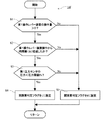
- FIG. 4 is a flowchart showing the processing contents of the sticking detection determination unit of the control device constituting the first embodiment of the construction machine of the present invention.
- the control device 14 inputs the operation signal of the first operating lever device 13 and the discharge pressure signal of the first open circuit pump 12 of the first pressure sensor 18, and the first assist valve 15 and the first pressure signal in response to these signals.
- the first surplus flow control valve 16 is controlled to determine whether or not the first surplus flow control valve is stuck open, and the discharge flow rates of the first closed circuit pump 11 and the first open circuit pump 12 are controlled.
- the control device 14 includes an operation amount detection unit 14a, a pressure detection unit 14b, an assist valve control unit 14c, an excess flow rate control valve control unit 14d, a pump discharge control unit 14e, and a sticking detection.
- a determination unit 14f and a stop signal generation unit 14g are provided.
- the operation amount detection unit 14a receives an operation amount signal from the first operation lever device 13, and as an extension drive command value amount or a contraction drive command value amount of the boom cylinder 1, the sticking detection determination unit 14f and each control unit 14c, 14d and 14e.
- the pressure detection unit 14b receives the discharge pressure signal of the first open circuit pump 12 from the first pressure sensor 18, and outputs it as the pressure signal of the flow path 202 to the adhesion detection determination unit 14f.
- the assist valve control unit 14c and the surplus flow control valve control unit 14d are signals of the extension drive command value amount or the contraction drive command value amount of the boom cylinder 1 and the opening of the first surplus flow control valve 16 from the operation amount detection unit 14a.
- a stop signal to be described later is input from the stop signal generator 14g, and a control command signal is output to the first assist valve 15 and the first surplus flow control valve 16 in accordance with these signals. To do.
- each of the assist valve control unit 14c and the surplus flow control valve control unit 14d includes, for example, a preset table based on the extension drive command value amount or the contraction drive command value amount from the operation amount detection unit 14a.
- the control command signals according to these tables are calculated and output.
- the surplus flow control valve control unit 14d is operated when the extension drive command value amount or the contraction drive command value amount from the operation amount detection unit 14a is larger than 0, that is, when the first operation lever device 13 is operated (operation start). At the time), a closing signal is immediately output as a control command value to the first surplus flow control valve 16.
- the assist valve control unit 14c when the extension drive command value amount or the contraction drive command value amount from the operation amount detection unit 14a becomes larger than 0, that is, when the first operation lever device 13 is operated (operation start) At the time), a control signal value to the first assist valve 15 is continuously output as a control command value to the first assist valve 15, and after a predetermined time difference ( ⁇ t) has elapsed from the start of the operation, A fully open signal is output as a value.
- a stop signal to be described later is input from the stop signal generator 14g, and in response to these signals, control command signals for controlling the discharge flow rates of the first closed circuit pump 11 and the first open circuit pump 12 are calculated, A control command signal is output to each regulator 11a, 12a.
- the sticking detection determination unit 14f has a function of detecting open sticking of the first surplus flow control valve 16. Specifically, at a predetermined timing, a predetermined pressure threshold is compared with the pressure signal of the flow path 202 from the pressure detection unit 14b, and if the pressure signal is equal to or less than the threshold, the first surplus flow rate It is determined that the control valve 16 is open and stuck, and an open and sticking judgment flag is output to the stop signal generator 14g.
- the operation of the control device 14 will be described.
- the surplus flow control valve control unit 14 d immediately outputs a fully closed signal as a control command value to the first surplus flow control valve 16.
- the pump discharge controller 14e immediately outputs a control command signal for controlling the discharge flow rates of the first closed circuit pump 11 and the first open circuit pump 12, respectively.
- the first assist valve 15 also receives the fully closed command and has not yet received the open command signal. For this reason, in the schematic diagram shown in FIG.
- the pressure oil from the first open circuit pump 12 flows into the flow path 202, but the first assist valve 15 and the first surplus flow control valve 16 are closed.
- the pressure in the flow path 202 measured by the first pressure sensor 18 is predicted to increase.
- a predetermined time difference ( ⁇ t) After a predetermined time difference ( ⁇ t) has elapsed, an opening command is output to the first assist valve 15, and the first open circuit pump 12 is connected to the boom cylinder. Therefore, if the pressure in the flow path 202 is equal to or less than a predetermined threshold during the predetermined time difference ( ⁇ t), it is determined that the first surplus flow control valve 16 is open and stuck.
- the stop signal generation unit 14g generates each stop signal and outputs it to the respective control unit when the open adhesion determination flag of the first surplus flow control valve 16 is input from the adhesion detection determination unit 14f. For example, a signal for closing the first assist valve 15 to the assist valve control unit 14c and a signal for setting the discharge command value of the first open circuit pump 12 to 0 are output to the pump discharge control unit 14e, and the flow path 202 is boomed. Shut off from cylinder 1. As a result, it is possible to prevent the hydraulic oil from being discharged from the boom head 1 a of the boom cylinder 1 to the tank 17 via the first surplus flow control valve 16. As a result, rapid contraction of the boom cylinder 1 can be prevented.
- the sticking detection determination unit 14f determines whether or not the operation amount of the first operation lever device 13 is greater than 0 (step S1). Specifically, it is determined whether or not the extension drive command value amount or the contraction drive command value amount from the operation amount detection unit 14a is greater than 0 (whether or not the first operation lever device 13 is operated), and the operation is performed. Identify the start time. If the operation amount is larger than 0, the process proceeds to step S2, and otherwise, the process proceeds to step S5.
- the sticking detection determination unit 14f determines whether or not a predetermined time difference ( ⁇ t) has elapsed since the first operating lever device 13 was operated (at the start of the operation) (step S2). If the predetermined time difference ( ⁇ t) has not elapsed, the process proceeds to step S3. Otherwise, the process proceeds to step S5.
- the sticking detection determination unit 14f determines whether or not the pressure measured by the first pressure sensor 18 is less than a preset threshold value Ps (step S3). Specifically, it is determined whether or not the pressure signal of the flow path 202 that is the discharge pressure of the first open circuit pump 12 from the pressure detection unit 14b is less than a predetermined pressure threshold value Ps. If the measured pressure is less than the threshold value Ps, the process proceeds to step S4. Otherwise, the process proceeds to step S5.
- the sticking detection determination unit 14f sets the open sticking determination flag to 1 (step S4). Specifically, when all the determinations in steps S1 to S3 described above are YES, that is, the first operation lever device 13 is operated (step S1), and the elapsed time is within a predetermined time difference ( ⁇ t). (Step S2) If the pressure value measured by the first pressure sensor 18 is less than the threshold value Ps, the sticking detection determination unit 14f sets the open sticking determination flag to 1, and the first surplus flow control valve 16 Judged to be open adhesion.
- the sticking detection determination unit 14f sets the open sticking determination flag to 0 (step S5).
- the open sticking determination flag is 1 for open sticking and 0 for normal.
- step S4 After finishing the process of step S4 or step S5, the sticking detection determination unit 14f returns and executes the next process from step 1.
- FIG. 5 is a characteristic diagram showing an example of time-series operations when the boom cylinder of the first embodiment of the construction machine of the present invention is extended
- FIG. 6 is a first embodiment of the construction machine of the present invention. It is a characteristic view which shows an example of a time-sequential operation
- the hydraulic circuit in a state where the boom cylinder 1 is stopped will be described.
- the control device 14 inputs an operation amount signal of the first operation lever device 13 via a signal line, and, for example, based on a preset table, the assist valve
- the control unit 14 c outputs a close signal to the first assist valve 15, and the surplus flow control valve control unit 14 d outputs an open command to the first surplus flow control valve 16.
- the pump discharge control unit 14e outputs the pump discharge flow rate command values of the first closed circuit pump 11 and the first open circuit pump 12 to 0 according to the operation amount. Since the discharge flow rates of the first closed circuit pump 11 and the first open circuit pump 12 are 0 and the first assist valve 15 is also controlled to be in the shut-off state, the boom cylinder 1 stops.
- FIG. 5 shows an example of each control signal and the pressure value of the flow path 202 when the boom cylinder 1 is set in the extending operation state.
- the horizontal axis indicates time
- the vertical axis indicates (a) first operation lever device 13 boom cylinder extension command, (b) first open circuit pump 12 discharge command value, and (c) first surplus.
- the flow control valve 16 control command value, (d) the first assist valve 15 control command value, and (e) the detected pressure of the first pressure sensor 18 are shown.
- Time t1 indicates the time when the first operating lever device 13 is operated
- time t2 indicates the time when a predetermined time difference ( ⁇ t) has elapsed from time t1.
- the operation amount detection unit 14a of the control device 14 uses the extension drive command value as the surplus flow control valve control unit 14d and the pump discharge control. 14e and the assist valve controller 14c (time t1).
- the surplus flow control valve control unit 14d immediately outputs a fully closed signal as a control command value to the first surplus flow control valve 16 based on a preset table, and the pump discharge control unit 14e receives the first closed circuit.
- a control command signal for controlling the discharge flow rates of the pump 11 and the first open circuit pump 12 is immediately output, and hydraulic oil is discharged.
- the assist valve control unit 14c continues to output a close signal as a control command value to the first assist valve 15 based on a preset table, and after a predetermined time difference ( ⁇ t) has elapsed from time t1. An opening command is output to the first assist valve 15 at time t2.
- the pressure detection unit 14b of the control device 14 outputs the pressure signal of the flow path 202 to the adhesion detection determination unit 14f, and the adhesion detection determination unit 14f performs the predetermined time difference ( ⁇ t) according to the characteristic diagram shown in FIG.
- ⁇ t the predetermined time difference
- the pressure in the flow path 202 is compared with a predetermined threshold value Ps, and if the pressure is higher than the threshold value Ps, it is determined that the first surplus flow control valve 16 is normal. On the other hand, when the pressure is lower than the threshold value Ps, it is determined that the first surplus flow control valve 16 is open and fixed.
- FIG. 6 shows an example of each control signal and the pressure value of the flow path 202 when the boom cylinder 1 is in the contracted operation state.
- the horizontal axis indicates time
- the vertical axis indicates (a) first operation lever device 13 boom cylinder contraction command, (b) first open circuit pump 12 discharge command value, and (c) first surplus.
- the flow control valve 16 control command value, (d) the first assist valve 15 control command value, and (e) the detected pressure of the first pressure sensor 18 are shown.
- Time t1 indicates the time when the first operating lever device 13 is operated
- time t2 indicates the time when a predetermined time difference ( ⁇ t) has elapsed from time t1.
- the operation amount detection unit 14a of the control device 14 uses the contraction drive command value as the surplus flow control valve control unit 14d, the pump discharge control. 14e and the assist valve controller 14c (time t1).
- the surplus flow control valve control unit 14d immediately outputs a fully closed signal as a control command value to the first surplus flow control valve 16 based on a preset table, and the pump discharge control unit 14e receives the first closed circuit.
- a control command signal for controlling the discharge flow rates of the pump 11 and the first open circuit pump 12 is immediately output, and hydraulic oil is discharged.
- the assist valve control unit 14c continues to output a close signal, and outputs an opening command to the first assist valve 15 at time t2 after a predetermined time difference ( ⁇ t) has elapsed from time t1.
- the pressure detection unit 14b of the control device 14 outputs the pressure signal of the flow path 202 to the sticking detection determination unit 14f, and the sticking detection determination unit 14f has the predetermined time difference ( ⁇ t) according to the characteristic diagram shown in FIG.
- ⁇ t the predetermined time difference
- the pressure in the flow path 202 is compared with a predetermined threshold value Ps, and if the pressure is higher than the threshold value Ps, it is determined that the first surplus flow control valve 16 is normal.
- the pump discharge control unit 14e outputs a control command signal for setting the discharge flow rate to 0 to the first open circuit pump 12, and the surplus flow control valve control unit 14d adjusts the opening amount of the surplus flow control valve, For example, a semi-closed signal is output to control the contraction speed of the boom cylinder 1.
- the threshold value Ps it is determined that the first surplus flow control valve 16 is open and fixed.
- the first surplus flow control valve 16 when the first surplus flow control valve 16 operates normally without being stuck open, when the first operation lever device 13 is operated by the operator, the first surplus flow control valve 16 is The first open circuit pump 12 discharges the hydraulic oil, and the first assist valve 15 is closed for the predetermined time difference ( ⁇ t) shown in FIG. The hydraulic fluid is sealed in the closed flow path 202. From this, the pressure in the flow path 202 rises.
- the sticking detection determination unit 14f determines that the first surplus flow control valve 16 is normal when the pressure in the flow path 202 rises to a pressure threshold value Ps or more shown in FIG.
- the assist valve control unit 14c does not receive the stop signal due to the open fixation from the sticking detection determination unit 14f and the stop signal generation unit 14g, and therefore the assist valve control unit 14c returns to the first assist valve 15 after a predetermined time difference ( ⁇ t) shown in FIG. Output open command.
- ⁇ t time difference
- the first surplus flow control valve 16 when the first surplus flow control valve 16 is fixed open, when the first operation lever device 13 is operated by the operator, the first surplus flow control valve 16 receives a close command, but remains open. . In this state, even if the first open circuit pump 12 discharges the hydraulic oil and the first assist valve 15 is closed for the predetermined time difference ( ⁇ t) shown in FIG. The hydraulic oil is discharged to the tank 17 through the valve 16. As a result, the pressure in the flow path 202 does not increase, and generally becomes a low pressure close to the tank pressure. When the pressure in the flow path 202 is less than the pressure threshold value Ps shown in FIG. 5, the sticking detection determination unit 14f determines that the first surplus flow control valve 16 is open sticking.
- the stop signal generation unit 14g when the sticking detection determination unit 14f determines that the first surplus flow control valve 16 is open sticking, the stop signal generation unit 14g outputs a close signal to the first assist valve 15, for example. Since the flow path 202 is blocked, the hydraulic oil from the boom head 1a is prevented from being discharged to the tank 17 via the first surplus flow control valve 16. This prevents sudden contraction of the boom cylinder 1. Furthermore, when the boom cylinder 1 is driven, the open adhering of the first surplus flow control valve 16 is checked in real time every time, so that it is possible to suppress a decrease in work efficiency of the construction machine.
- the open adhesion of the first surplus flow control valve 16 can be detected in real time during the operation of the construction machine, it is possible to suppress a decrease in work efficiency.
- a pressure shock that occurs when the first assist valve 15 is opened in a sequence similar to the present embodiment can be suppressed.
- the first assist valve 15 is closed, and the hydraulic fluid is discharged from the first open circuit pump 12 with the first surplus flow control valve 16 closed, After increasing the pressure in the flow path 202 to a predetermined value, the first assist valve 15 is opened.
- the predetermined pressure in the target flow path 202 is set to a pressure substantially equal to the boom head 1a.
- the pressure threshold value Ps set in the embodiment of the present invention is different in that the pressure threshold value Ps is set to a slightly higher pressure, for example, about 1 to 2 MPa than the pressure of the tank 17.
- FIG. 7 is a schematic diagram showing a hydraulic drive unit constituting a second embodiment of the construction machine of the present invention
- FIG. 8 shows a configuration of a control unit constituting the second embodiment of the construction machine of the present invention. It is a conceptual diagram. 7 and 8, since the same reference numerals as those shown in FIGS. 1 to 6 are the same parts, detailed description thereof will be omitted.
- a boom cylinder 1 and an arm cylinder 3 as first and second hydraulic cylinders, and a circuit in which first and second closed circuit pumps 11 and 25 are connected by a hydraulic closed circuit, respectively,
- the second open circuit pumps 12 and 26 are respectively connected to the flow paths on the cylinder head side of the hydraulic closed circuit, and the first and second closed circuit pumps 11 and 25 and the first and second open circuit pumps are interlocked.
- first and second surplus flow control valves 16 and 28 are fixed open, the boom cylinder 1 or the arm cylinder 3 can be driven without stopping the construction machine by the contraction operation control unit 33 of the control device 14.
- a second closed circuit pump 25 and a second hydraulic cylinder 3 connected to the second closed circuit pump 25 in a closed circuit shape are provided with respect to the first embodiment.
- a second open circuit unit including a second surplus flow control valve.
- the second embodiment of the construction machine of the present invention shown in FIG. 7 is composed of almost the same equipment as the first embodiment, but differs in the following configuration.
- a boom cylinder 1 and an arm cylinder 3 are connected to the first and second closed circuit pumps 11 and 25 as the first and second hydraulic cylinders by a hydraulic closed circuit, respectively.
- the first and second closed circuit pumps 11 and 25 and the first and second open circuit pumps 12 and 26 are driven by an engine (not shown), and each of the tilting swash plate mechanisms having a pair of input / output ports as a flow rate adjusting device, And regulators 11a, 25a, 12a, and 26a for adjusting the displacement of the pump by adjusting the inclination angle of the swash plate.
- the regulators 11a, 25a, 12a, and 26a are connected to the discharge flow rates of the first and second closed circuit pumps 11 and 25 according to the pump discharge flow rate command values received from the control device 14 via signal lines, respectively.
- the discharge flow rate of the open circuit pumps 12 and 26 is controlled.
- a first operation lever device 13a for driving the boom cylinder 1 and a second operation lever device 13b for driving the arm cylinder 3 are provided.
- flow path switching valves 29 to 32 are provided as the flow path switching circuit.
- One discharge port of the first closed circuit pump 11 is connected to flow path switching valves 29 and 30 as a flow path switching circuit via a flow path 200.
- the flow path switching valves 29 and 30 are controlled in the flow state and switching direction of the flow path by a signal via the signal line from the degeneration operation control unit 33 of the control device 14 and are shut off when there is no signal.
- the other discharge port of the first closed circuit pump 11 is connected to the flow path switching valves 29 and 30 via the flow path 201.
- the flow path switching valve 29 is connected to the boom cylinder 1 via the flow paths 200a and 201a.
- the first closed circuit pump 11 is connected to the boom cylinder 1 via the flow path.
- the flow path switching valve 30 is connected to the arm cylinder 3 via the flow paths 208, 209, 204 a, 205 a, and when the flow path switching valve 30 is in a flow state, the first closed circuit pump 11 is connected to the arm cylinder 3. It is connected via a flow path.
- one discharge port of the second closed circuit pump 25 is connected to the flow path switching valves 31 and 32 as the flow path switching circuit via the flow path 204.
- the flow path switching valves 31 and 32 are controlled in the flow direction and switching direction of the flow path by a signal via the signal line from the degeneration operation control unit 33 of the control device 14, and are controlled to be cut off when there is no signal.
- the other discharge port of the second closed circuit pump 25 is connected to the flow path switching valves 31 and 32 via the flow path 205.
- the flow path switching valve 31 is connected to the boom cylinder 1 via the flow paths 210, 211, 200 a, 201 a, and when the flow path switching valve 31 enters a flow state, the second closed circuit pump 25 is connected to the boom cylinder 1. It is connected via a flow path.
- the flow path switching valve 32 is connected to the arm cylinder 3 via the flow paths 204a and 205a. When the flow path switching valve 32 is in a flow state, the second closed circuit pump 25 is connected to the arm cylinder 3 via the flow path. Connected.
- the discharge port of the first open circuit pump 12 is connected to the flow path 200 via the flow path 202 and the first assist valve 15 which is a switching valve, and the discharge port of the second open circuit pump 26 is connected to the flow path 206 and the switching valve. Is connected to the flow path 204 through the second assist valve 27.
- the flow path 202 and the flow path 206 are each provided with a branch portion, and one end side of the flow paths 203 and 207 with the other end side connected to the tank 17 is connected to the branch portion.
- the flow paths 203, 207 are provided with first and second surplus flow control valves 16, 28, respectively.
- a first pressure sensor 18a and a second pressure sensor 18b are provided in the flow path 202 and the flow path 206, respectively, and the first and second open circuit pumps 12, 26 detected by the first and second pressure sensors 18a, 18b.
- the discharge pressure signal is input to the control device 14 via a signal line.
- operation signals from the operators of the first and second operation lever devices 13a and 13b are input to the control device 14 via signal lines.
- control device 14 constituting this embodiment will be described with reference to FIG.
- the configuration of the control device 14 in the present embodiment is different from the first embodiment in that a switching valve control unit 14h that controls opening and closing of the flow path switching valves 29 to 32 is additionally provided as a switching circuit control unit. That is, the stop signal generation unit 14g is configured to function as the degeneration operation control unit 33.
- the switching valve control unit 14h is configured to output the extension drive command value amount or the contraction drive command value amount signal of the boom cylinder 1 or the arm cylinder 3 from the operation amount detection unit 14a, and any of the first and second surplus flow control valves 16 and 28.
- a control command signal described later is input from the degeneration operation control unit 33, and a control command for driving the flow path switching valves 29 to 32 is output in accordance with these signals. .
- the degeneracy operation control unit 33 receives the signal of the extension drive command value amount or the contraction drive command value amount of the boom cylinder 1 or the arm cylinder 3 from the operation amount detection unit 14a, and the first and second surplus flow control from the adhesion detection determination unit 14f. An open sticking determination flag of the valves 16 and 28 is input.
- the degeneracy operation control unit 33 generates a control command value signal when the open adhesion determination flag of any of the first and second surplus flow control valves 16 and 28 is input, and each of the control units 14c to 14e, To 14h. For example, without using an open circuit pump and a closed circuit pump connected to an open excess flow control valve, control is performed so that cylinder drive control corresponding to the operation amount is realized using a normal excess flow control valve. A command value signal is generated and controlled.
- the operation when the first surplus flow control valve 16 shown in FIG. Similar to the first embodiment, when the first surplus flow control valve 16 opens and adheres when the boom cylinder 1 is extended by the first operating lever device 13a, the same as the first embodiment shown in FIG.
- the sticking detection determination unit 14f determines that the first surplus flow control valve 16 is open and stuck, and the open sticking judgment flag of the first surplus flow control valve 16 is degenerated. Output to the operation control unit 33.
- the degeneration operation control unit 33 outputs a command signal to the assist valve control unit 14c and the switching valve control unit 14h, and outputs a closing signal to the first assist valve 15 and the flow path switching valve 29 corresponding to the first open circuit pump 12. To do.
- the degeneration operation control unit 33 A command signal is output to the discharge control unit 14e, and the discharge flow rates of the second closed circuit pump 25 and the second open circuit pump 26 are controlled so as to correspond to the operation amount of the first operation lever device 13a, and the second An opening operation signal is output to the assist valve 27 and a closing signal is output to the second surplus flow control valve 28.
- the boom cylinder 1 when the first surplus flow control valve 16 is fixed open, the boom cylinder 1 can be stopped by closing the first assist valve 15, and the unintended boom cylinder 1 can be stopped. It was possible to suppress the operation. However, since the boom cylinder 1 cannot be driven, there is a grudge that work efficiency is lowered. In this embodiment, in such a case, the boom cylinder 1 can be driven using another closed circuit, so that the boom cylinder 1 can be driven even if the first surplus flow control valve 16 is stuck open, A decrease in work efficiency can be suppressed.
- the boom and the arm are described as examples of the drive target of the hydraulic cylinder.
- the present invention is not limited to this. You may apply to any hydraulic cylinder of a boom, an arm, or a bucket.
- the present invention is not limited to this.
- the arm cylinder 3 when the arm cylinder 3 is extended and retracted, the arm cylinder 3 can be driven by controlling the closed circuit pump, the open circuit pump, and the switching valve connected to the surplus flow control valve that operates normally. good.
- FIG. 9 is a schematic diagram showing a hydraulic drive unit constituting a third embodiment of the construction machine of the present invention
- FIG. 10 shows a configuration of a control unit constituting the third embodiment of the construction machine of the present invention. It is a conceptual diagram. 9 and 10, the same reference numerals as those shown in FIGS. 1 to 8 are the same parts, and the detailed description thereof is omitted.
- the third embodiment of the construction machine of the present invention shown in FIG. 9 is composed of almost the same equipment as the first embodiment, the following construction is different.
- the present embodiment is different in that a failure notification unit 34 is additionally provided in the control device 14 and a failure notification device 35 connected to the control device 14 via a signal line is provided.
- the failure notification unit 34 receives the open sticking determination flag from the sticking detection determination unit 14f via the stop signal generation unit 14g, and based on the value, information on the open flow rate control valve that has been stuck open is obtained. Output to the failure notification device 35.
- the information on the surplus flow control valve is, for example, the arrangement position, manufacturing number, and failure occurrence time of the surplus flow control valve that has failed.
- the failure notification unit 34 of the control device 14 When the first surplus flow control valve 16 shown in FIG. 9 is stuck open, the failure notification unit 34 of the control device 14 outputs information on the first surplus flow control valve 16 to the failure notification device 35, so that the operator Alternatively, the maintenance worker can grasp from the failure notification device 35 the arrangement position and failure normal state of the surplus flow control valve that has failed.
- the failure notification unit 34 and the failure notification device 35 are provided, when the first surplus flow control valve 16 is stuck open, Detailed information such as the position of the surplus flow control valve that has failed and the failure state can be promptly notified to the operator or maintenance worker. As a result, the time required for maintenance such as component replacement can be shortened. As a result, the downtime of the construction machine can be shortened and the operating rate can be improved.
- the failure notification device 35 may be a display device such as a display or a sound notification means such as a speaker. Further, in the present embodiment, the case of notifying the first sticking of the first surplus flow control valve 16 is described as an example, but not only the sticking of the first surplus flow control valve 16 but the first surplus flow control valve 16 remains closed. You may notify the closed adhering which is a malfunction.
- the present invention is not limited to the above-described embodiments, and includes various modifications within the scope not departing from the gist thereof.
- the present invention can also be applied to construction machines other than the hydraulic excavator.
- the present invention can be applied to all construction machines including a hydraulic device that drives a plurality of hydraulic actuators by a closed circuit in a working device such as a hydraulic crane.
Landscapes
- Engineering & Computer Science (AREA)
- General Engineering & Computer Science (AREA)
- Fluid Mechanics (AREA)
- Physics & Mathematics (AREA)
- Mechanical Engineering (AREA)
- Structural Engineering (AREA)
- Civil Engineering (AREA)
- Mining & Mineral Resources (AREA)
- Chemical & Material Sciences (AREA)
- Analytical Chemistry (AREA)
- Fluid-Pressure Circuits (AREA)
- Operation Control Of Excavators (AREA)
- Component Parts Of Construction Machinery (AREA)
Abstract
作業速度を低下させずに、作業中にリアルタイムで余剰流量制御弁の開固着を検知できる建設機械を提供する。操作レバー装置の操作量信号を検出した操作開始時に、余剰流量制御弁に閉指令を出力する余剰流量制御弁制御部と、開回路ポンプの調整器に吐出流量指令を出力するポンプ吐出制御部と、アシスト弁に以前からの閉指令を出力し続けるアシスト弁制御部と、圧力信号と予め設定した閾値とを比較し、圧力信号が閾値未満であれば、余剰流量制御弁は開固着であると判定し、圧力信号が閾値超過であれば、余剰流量制御弁は正常であると判定する固着検知判定部と、固着判定信号を入力し、開固着の場合にはアシスト弁の閉止状態を維持する制御信号をアシスト弁制御部へ出力し、正常の場合には、アシスト弁を開動作させる制御信号をアシスト弁制御部へ出力する停止信号生成部とを備えた。
Description
本発明は建設機械に関する。
油圧ショベル等の建設機械の分野において、油圧システムの省エネを目的として、両傾転油圧ポンプ(以下、閉回路ポンプともいう)と油圧アクチュエータとを閉回路状に接続し、両傾転油圧ポンプの吐出流量制御により、油圧アクチュエータの駆動速度を制御して、油圧アクチュエータからの戻り油を閉回路ポンプに戻す閉回路の油圧駆動システムがある(例えば、特許文献1参照)。
また、一般的な油圧装置で用いられる油圧比例弁(以下、比例弁ともいう)の固着故障を検出する故障診断装置がある(例えば、特許文献2参照)。この比例弁の故障診断装置は、ポンプ、アキュムレータ、および、比例弁を有する車両用油圧装置の比例弁の故障診断装置であって、前記比例弁を駆動するための比例弁指示電流を出力する比例弁駆動指示手段と、前記ポンプのポンプ圧力を測定する圧力計測手段と、前記比例弁指示電流と前記ポンプ圧力とに基づいて、前記比例弁の固着判定を行う比例弁固着判定手段とを備え、前記比例弁固着判定手段は、前記ポンプの停止時のポンプ圧力を記憶する第一圧力記憶手段と、前記ポンプの停止後から所定時間経過後のポンプ圧力を記憶する第二圧力記憶手段と、前記第一圧力記憶手段と前記第二圧力記憶手段にそれぞれ記憶した前記ポンプ圧力の差分を計算する第一圧力差分計算手段とを有し、前記ポンプを所定時間作動して圧力を上昇させた後に、前記ポンプを停止して、前記比例弁を「閉」指示したときに、前記第一圧力差分計算手段にて計算した前記ポンプ圧力の差分が所定値以上の場合に、前記比例弁の開固着故障であると判定することを特徴とする。
上述した特許文献1に記載の閉回路の油圧駆動システムは、油圧アクチュエータが片ロッド油圧シリンダである場合、ピストンのヘッド油室側受圧部とロッド油室側受圧部の面積が異なることから、ピストンの動作に伴い油圧シリンダに流入する作動油量と油圧シリンダから流出する作動油量が異なる。このことから、閉回路の内部において、作動油量が過多になる部位と不足する部位とが生じる。
このような閉回路の内部における作動油量の過不足を抑制するために、油圧シリンダのヘッド油室側には、切換弁を介して不足分の作動油を供給する片傾転油圧ポンプ(以下、開回路ポンプという)が接続され、開回路ポンプと切換弁との間には、余剰分の作動油をタンクへ排出可能とする油圧比例弁が設けられている。この油圧比例弁を余剰流量制御弁という。
例えば、1つの油圧シリンダを伸展方向に駆動する場合、切換弁を開動作させて、閉回路ポンプと共に開回路ポンプから作動油を油圧シリンダヘッド油室側に供給し、油圧シリンダロッド油室側からの戻り油を閉回路ポンプで吸入する。このとき、余剰流量制御弁は閉じている。一方、油圧シリンダを収縮方向に駆動する場合は、閉回路ポンプから作動油を油圧シリンダロッド油室側に供給し、油圧シリンダヘッド油室側からの戻り油を閉回路ポンプで吸入する。このとき、切換弁と余剰流量制御弁とを開動作させて、油圧シリンダヘッド油室側からの戻り油の余剰分をタンクへ排出する。このとき、開回路ポンプは作動油を吐出しない。
このような油圧駆動システムを構成する余剰流量制御弁において、例えば、内部流路が開いたままの状態になる開固着という不具合が発生すると、油圧シリンダ内の圧油が、開固着した余剰流量制御弁を介してタンクに排出されてしまう。これにより油圧シリンダが、意図しない方向に急激に動作する可能性が発生し、建設機械の操作性を低下させる。
上述した特許文献2に記載の比例弁の故障診断装置は、一度装置を停止させて、ポンプの停止と比例弁の「閉」指示が必要になる。特許文献1に記載の作業機械(建設機械)に特許文献2に記載の故障診断装置を適用した場合には、余剰流量制御弁の開固着の判定のために、一度装置を停止させて切換弁を閉じ、開回路ポンプを起動し、余剰流量制御弁を閉じた際に発生する開回路ポンプの圧力値を計測して判定する必要がある。したがって、この間、開回路ポンプによって油圧シリンダを駆動することはできず、建設機械の作業も停止する必要が生じる。この結果、全体の作業速度が低下し生産性を悪化させてしまう。
本発明は上述した事柄に基づいてなされたものであって、その目的は、建設機械の作業速度を低下させずに、作業中にリアルタイムで余剰流量制御弁の開固着を検知できる建設機械を提供することにある。
上記課題を解決するために、例えば特許請求の範囲に記載の構成を採用する。本願は、上記課題を解決する手段を複数含んでいるが、その一例を挙げるならば、第1閉回路ポンプと、前記第1閉回路ポンプと閉回路状に接続された第1油圧シリンダとを備えた第1閉回路ユニットと、前記第1油圧シリンダのヘッド油室側流路に切換弁である第1アシスト弁を介して接続された第1開回路ポンプと、前記第1開回路ポンプと前記第1アシスト弁との間の流路である第1開回路ポンプ吐出側流路から分岐した流路に配置され、前記第1油圧シリンダのヘッド油室からの作動油をタンクへ排出可能とする第1余剰流量制御弁とを備えた第1開回路ユニットと、前記第1油圧シリンダの動作を指示する第1操作レバー装置と、前記第1開回路ポンプ吐出側流路の圧力を計測する第1圧力センサと、前記第1閉回路ポンプと前記第1開回路ポンプの吐出流量をそれぞれ調整する複数の調整器と、前記第1余剰流量制御弁と前記第1アシスト弁と前記複数の調整器にそれぞれ指令信号を出力する制御装置とを有する制御ユニットとを備えた建設機械において、前記制御装置は、前記第1圧力センサが計測した前記第1開回路ポンプ吐出側流路の第1圧力信号を取込む圧力検出部と、前記第1操作レバー装置からの操作量信号を取込む操作量検出部と、前記操作量検出部が前記第1操作レバー装置の操作量信号を検出した操作開始時に、前記第1余剰流量制御弁に閉指令を出力する余剰流量制御弁制御部と、前記操作開始時に、前記第1開回路ポンプの前記調整器に吐出流量指令を出力するポンプ吐出制御部と、前記操作開始時に、前記第1アシスト弁に閉指令を出力するアシスト弁制御部と、前記圧力検出部からの第1圧力信号と予め設定した閾値とを比較し、前記第1圧力信号が前記閾値未満であれば、前記第1余剰流量制御弁は開固着であると判定し、前記第1圧力信号が前記閾値超過であれば、前記第1余剰流量制御弁は正常であると判定する固着検知判定部と、前記固着検知判定部からの固着判定信号を入力し、開固着の場合には前記第1アシスト弁の閉止状態を維持する制御信号を前記アシスト弁制御部へ出力し、正常の場合には、前記第1アシスト弁を開動作させる制御信号を前記アシスト弁制御部へ出力する停止信号生成部とを備えたことを特徴とする。
本発明によれば、建設機械の稼働中に余剰流量制御弁の開固着をリアルタイムに検知できるので、作業効率の低下を抑制できる。
以下、建設機械として油圧ショベルを例にとって本発明の実施の形態を図面を用いて説明する。なお、本発明は、閉回路ポンプと閉回路状に接続された油圧シリンダと、油圧シリンダのヘッド油室側に接続された開回路ポンプと余剰流量制御弁とを備えた建設機械全般に適用が可能であり、本発明の適用は油圧ショベルに限定されるものではない。
従来技術の余剰流量制御弁を用いた閉回路による油圧シリンダ駆動回路においては、余剰流量制御弁が開固着した場合、油圧シリンダヘッド油室側の作動油がタンクへ排出され、油圧シリンダが意図しない収縮動作をするという課題がある。
そこで、本発明の第1の実施の形態では、建設機械が、第1閉回路ポンプと、前記第1閉回路ポンプと閉回路状に接続された第1油圧シリンダとを備えた第1閉回路ユニットと、前記第1油圧シリンダのヘッド油室側に切換弁である第1アシスト弁を介して接続された第1開回路ポンプと、前記第1開回路ポンプと前記第1アシスト弁との間に配置され、前記第1油圧シリンダのヘッド油室側からの圧油の余剰分をタンクへ排出可能とする第1余剰流量制御弁とを備えた第1開回路ユニットと、前記第1油圧シリンダの動作を指示する第1操作レバー装置と、ポンプ吐出制御部とアシスト弁制御部と余剰流量制御弁制御部とを備えた制御装置と、前記第1開回路ポンプの吐出側流路に設けられ、前記第1開回路ポンプの吐出圧力を計測する圧力センサとを有する制御ユニットとを備えている。
そこで、本発明の第1の実施の形態では、建設機械が、第1閉回路ポンプと、前記第1閉回路ポンプと閉回路状に接続された第1油圧シリンダとを備えた第1閉回路ユニットと、前記第1油圧シリンダのヘッド油室側に切換弁である第1アシスト弁を介して接続された第1開回路ポンプと、前記第1開回路ポンプと前記第1アシスト弁との間に配置され、前記第1油圧シリンダのヘッド油室側からの圧油の余剰分をタンクへ排出可能とする第1余剰流量制御弁とを備えた第1開回路ユニットと、前記第1油圧シリンダの動作を指示する第1操作レバー装置と、ポンプ吐出制御部とアシスト弁制御部と余剰流量制御弁制御部とを備えた制御装置と、前記第1開回路ポンプの吐出側流路に設けられ、前記第1開回路ポンプの吐出圧力を計測する圧力センサとを有する制御ユニットとを備えている。
そして、制御装置は、第1操作レバー装置による第1油圧シリンダ伸展信号が入力されると、第1アシスト弁に開指令を出力する前に第1余剰流量制御弁に閉指令を出力し、第1余剰流量制御弁を閉止する。そして、第1開回路ポンプの吐出流量を増加させるので、入力している第1開回路ポンプの吐出圧力信号が増加する。この吐出圧力信号の増加量が予め定めた閾値以下であった場合に、制御装置は第1余剰流量制御弁を開固着であると判定する。開固着であると判定した制御装置は、第1アシスト弁への開指令の出力を禁止して、第1アシスト弁の閉止状態を維持する。
これにより、建設機械の稼働中に余剰流量制御弁の開固着をリアルタイムに検知することができる。このことにより、稼働率の低下を抑制できる。また、余剰流量制御弁の開固着を検知するとアシスト弁を閉止するので、油圧シリンダの意図しない収縮動作を抑制でき、オペレータの意図しないフロント作業機の動作がより抑制された建設機械を提供できる。
図1は本発明の建設機械の第1の実施の形態である油圧ショベルを示す側面図、図2は本発明の建設機械の第1の実施の形態を構成する油圧駆動装置を示す概略図である。
図1において、本実施の形態に係る建設機械として、油圧ショベル100を例に説明する。油圧ショベル100は、左右方向の両側にクローラ式の走行装置8a,8bを備えた下部走行体103と、下部走行体103の上に旋回可能に取付けられた本体としての上部旋回体102とを備えている。上部旋回体102上にはオペレータが搭乗する操作室としてキャブ101が設けられている。下部走行体103と上部旋回体102とは、旋回油圧モータ7を介して旋回可能とされている。
図1において、本実施の形態に係る建設機械として、油圧ショベル100を例に説明する。油圧ショベル100は、左右方向の両側にクローラ式の走行装置8a,8bを備えた下部走行体103と、下部走行体103の上に旋回可能に取付けられた本体としての上部旋回体102とを備えている。上部旋回体102上にはオペレータが搭乗する操作室としてキャブ101が設けられている。下部走行体103と上部旋回体102とは、旋回油圧モータ7を介して旋回可能とされている。
上部旋回体102の前側には、例えば掘削作業等を行うための作動装置であるフロント作業機104の基端部が回動可能に取り付けられている。ここで、前側とは、キャブ101に搭乗するオペレータが向く方向(図1中の左方向)をいう。
フロント作業機104は、上部旋回体102の前側に基端部が俯仰動可能に連結されたブーム2を備えている。ブーム2は、供給される流体としての作動油(圧油)にて駆動する片ロッド式油圧シリンダであるブームシリンダ1を介して動作する。ブームシリンダ1は、ブームロッド1bの先端部が上部旋回体102に連結され、ブームヘッド1aの基端部がブーム2に連結されている。
ブーム2の先端部には、アーム4の基端部が俯仰動可能に連結されている。アーム4は、片ロッド式油圧シリンダであるアームシリンダ3を介して動作する。アームシリンダ3は、アームロッド3bの先端部がアーム4に連結され、アームシリンダ3のアームヘッド3aがブーム2に連結されている。
アーム4の先端部には、バケット6の基端部が俯仰動可能に連結されている。バケット6は、供給される作動油にて駆動する油圧アクチュエータとしての片ロッド式油圧シリンダであるバケットシリンダ5を介して動作する。バケットシリンダ5は、バケットロッド5bの先端部がバケット6に連結され、バケットシリンダ5のバケットヘッド5aの基端がアーム4に連結されている。
キャブ101には、フロント作業機104を構成するブーム2、アーム4、バケット6を操作するための操作部材である第1操作レバー装置13(図2参照)が配置されている。
次に、図2に示す概略図における油圧駆動装置のシステム構成を説明する。
図示しないエンジンから動力を受けて駆動される第1閉回路ポンプ11と第1開回路ポンプ12は、それぞれ流量調整手段として一対の入出力ポートを持つ傾転斜板機構、および斜板の傾斜角を調整してポンプ押しのけ容積を調整するレギュレータ11a,12aを備えている。レギュレータ11a,12aは、制御装置14から信号線を介して受信したポンプ吐出流量指令値に従い、第1閉回路ポンプ11と第1開回路ポンプ12の吐出流量をそれぞれ制御する。
図示しないエンジンから動力を受けて駆動される第1閉回路ポンプ11と第1開回路ポンプ12は、それぞれ流量調整手段として一対の入出力ポートを持つ傾転斜板機構、および斜板の傾斜角を調整してポンプ押しのけ容積を調整するレギュレータ11a,12aを備えている。レギュレータ11a,12aは、制御装置14から信号線を介して受信したポンプ吐出流量指令値に従い、第1閉回路ポンプ11と第1開回路ポンプ12の吐出流量をそれぞれ制御する。
第1閉回路ポンプ11の一方の吐出ポートは、流路201を介して第1油圧シリンダとしてのブームシリンダ1のロッド油室側に接続され、第1閉回路ポンプ11の他方の吐出ポートは、流路200を介してブームシリンダ1のヘッド油室側に接続され、閉回路を構成している。本実施の形態において、第1閉回路ポンプ11と閉回路上に接続されたブームシリンダ1とで第1閉回路ユニットを構成する。
第1開回路ポンプ12の吐出ポートは流路202と切換弁である第1アシスト弁15を介して、流路200へ接続されている。第1開回路ポンプ12の吸入ポートはタンク17に接続されている。
第1開回路ポンプ12と第1アシスト弁15との間の流路202には、分岐部が設けられ、この分岐部には、他端側をタンク17に接続された流路203の一端側が接続されている。流路203には、油圧比例弁である第1余剰流量制御弁16が設けられている。第1アシスト弁15および第1余剰流量制御弁16はそれぞれ、制御装置14から信号線を介して受信した指令信号に従い、開閉が制御される。本実施の形態において、第1開回路ポンプ12と第1アシスト弁15と第1余剰流量制御弁16とで第1開回路ユニットを構成する。
流路202には、第1開回路ポンプ12の吐出圧力を計測する第1圧力センサ18が設けられている。第1圧力センサ18が検出した第1開回路ポンプ12の吐出圧力信号は、信号線を介して制御装置14に入力されている。また、第1操作レバー装置13のオペレータによる操作信号は、信号線を介して制御装置14に入力されている。本実施の形態において、第1操作レバー装置13と第1圧力センサ18とレギュレータ11a,12aと制御装置14とで制御ユニットを構成する。
次に、本実施の形態を構成する制御装置14について図3及び図4を用いて説明する。図3は本発明の建設機械の第1の実施の形態を構成する制御装置の構成を示す概念図である。図4は本発明の建設機械の第1の実施の形態を構成する制御装置の固着検知判定部の処理内容を示すフローチャート図である。
制御装置14は、第1操作レバー装置13の操作信号と第1圧力センサ18の第1開回路ポンプ12の吐出圧力信号とを入力し、これらの信号に応じて、第1アシスト弁15と第1余剰流量制御弁16を制御し、第1余剰流量制御弁の開固着の有無を判定すると共に、第1閉回路ポンプ11と第1開回路ポンプ12の吐出流量をそれぞれ制御する。図3に示すように、制御装置14は、操作量検出部14aと、圧力検出部14bと、アシスト弁制御部14cと、余剰流量制御弁制御部14dと、ポンプ吐出制御部14eと、固着検知判定部14fと、停止信号生成部14gとを備えている。
操作量検出部14aは、第1操作レバー装置13からの操作量信号を入力し、ブームシリンダ1の伸展駆動指令値量または収縮駆動指令値量として、固着検知判定部14fと各制御部14c,14d,14eへ出力する。
圧力検出部14bは、第1圧力センサ18からの第1開回路ポンプ12の吐出圧力信号を入力し、流路202の圧力信号として、固着検知判定部14fへ出力する。
アシスト弁制御部14cと余剰流量制御弁制御部14dとは、操作量検出部14aからブームシリンダ1の伸展駆動指令値量または収縮駆動指令値量の信号と、第1余剰流量制御弁16の開固着が判定された場合には、停止信号生成部14gから後述する停止信号とを入力し、これらの信号に応じて、第1アシスト弁15および第1余剰流量制御弁16へ制御指令信号を出力する。
具体的には、アシスト弁制御部14cと余剰流量制御弁制御部14dはそれぞれ、操作量検出部14aからの伸展駆動指令値量または収縮駆動指令値量を基に、例えば予め設定したテーブルを備えており、停止信号生成部14gからの停止信号が入力されない場合には、これらのテーブルに従った制御指令信号を演算し出力する。
余剰流量制御弁制御部14dは、操作量検出部14aからの伸展駆動指令値量または収縮駆動指令値量が0より大きくなったとき、即ち第1操作レバー装置13が操作されたとき(操作開始時)に、第1余剰流量制御弁16への制御指令値として、閉止信号を直ちに出力する。一方、アシスト弁制御部14cは、操作量検出部14aからの伸展駆動指令値量または収縮駆動指令値量が0より大きくなったとき、即ち第1操作レバー装置13が操作されたとき(操作開始時)に、第1アシスト弁15への制御指令値として、以前からの閉止信号を出力し続け、操作開始時から所定の時間差(Δt)を経過した後に、第1アシスト弁15への制御指令値として、全開信号を出力する。
ポンプ吐出制御部14eは、操作量検出部14aからのブームシリンダ1の伸展駆動指令値量または収縮駆動指令値量の信号と、第1余剰流量制御弁16の開固着が判定された場合には、停止信号生成部14gから後述する停止信号とを入力し、これらの信号に応じて、第1閉回路ポンプ11と第1開回路ポンプ12の吐出流量をそれぞれ制御する制御指令信号を演算し、それぞれのレギュレータ11a,12aへ制御指令信号を出力する。
ポンプ吐出制御部14eは、操作量検出部14aからの伸展駆動指令値量または収縮駆動指令値量が0より大きくなったとき、即ち第1操作レバー装置13が操作されたとき(操作開始時)に、第1閉回路ポンプ11と第1開回路ポンプ12の吐出流量をそれぞれ制御する制御指令信号を直ちに出力する。
固着検知判定部14fは、第1余剰流量制御弁16の開固着を検出する機能を備えている。具体的には、所定のタイミングにおいて、予め定めた圧力の閾値と圧力検出部14bからの流路202の圧力信号とを比較し、圧力信号が閾値以下であった場合には、第1余剰流量制御弁16は開固着であると判定し、開固着判定フラグを停止信号生成部14gへ出力する。
ここで、制御装置14の動作を説明する。オペレータが第1操作レバー装置13を操作することにより、操作量検出部14aからの伸展駆動指令値量または収縮駆動指令値量が0より大きくなった(操作開始時)、即ち第1操作レバー装置13が操作されると、余剰流量制御弁制御部14dは、第1余剰流量制御弁16への制御指令値として、全閉信号を直ちに出力する。また、このときにポンプ吐出制御部14eは、第1閉回路ポンプ11と第1開回路ポンプ12の吐出流量をそれぞれ制御する制御指令信号を直ちに出力する。このとき第1アシスト弁15も全閉指令を受信し、まだ開指令信号を受信していない。このため、図2に示す概略図において、第1開回路ポンプ12からの圧油は、流路202に流入するが、第1アシスト弁15と第1余剰流量制御弁16とが閉状態のため、第1圧力センサ18で計測される流路202の圧力は、昇圧することが予測される。そして、所定の時間差(Δt)が経過した後に第1アシスト弁15へ開指令が出力され、第1開回路ポンプ12はブームシリンダと接続される。したがって、この所定の時間差(Δt)の間に、流路202の圧力が予め定めた閾値以下であった場合には、第1余剰流量制御弁16は開固着であると判定する。
停止信号生成部14gは、固着検知判定部14fから第1余剰流量制御弁16の開固着判定フラグを入力した場合に、各停止信号を生成して、それぞれの制御部へ出力する。例えば、アシスト弁制御部14cへ第1アシスト弁15を閉止する信号と、ポンプ吐出制御部14eへ第1開回路ポンプ12の吐出指令値を0とする信号とを出力し、流路202をブームシリンダ1と遮断する。このことにより、ブームシリンダ1のブームヘッド1aから作動油が第1余剰流量制御弁16を介してタンク17へと排出されるのを防ぐことができる。この結果、ブームシリンダ1の急激な収縮を防ぐことができる。
次に、固着検知判定部14fの処理内容を図4を用いて説明する。
固着検知判定部14fは、第1操作レバー装置13の操作量が0より大きいか否かを判断する(ステップS1)。具体的には、操作量検出部14aからの伸展駆動指令値量または収縮駆動指令値量が0より大きくなったか否か(第1操作レバー装置13が操作されたか否か)を判断し、操作開始時を特定する。操作量が0より大きい場合はステップS2へ進み、それ以外の場合はステップS5へ進む。
固着検知判定部14fは、第1操作レバー装置13の操作量が0より大きいか否かを判断する(ステップS1)。具体的には、操作量検出部14aからの伸展駆動指令値量または収縮駆動指令値量が0より大きくなったか否か(第1操作レバー装置13が操作されたか否か)を判断し、操作開始時を特定する。操作量が0より大きい場合はステップS2へ進み、それ以外の場合はステップS5へ進む。
固着検知判定部14fは、第1操作レバー装置13の操作されたとき(操作開始時)から、所定の時間差(Δt)が経過したか否かを判断する(ステップS2)。所定の時間差(Δt)を経過していない場合はステップS3へ進み、それ以外の場合はステップS5へ進む。
固着検知判定部14fは、第1圧力センサ18が計測した圧力が予め設定された閾値Ps未満か否かを判断する(ステップS3)。具体的には、圧力検出部14bからの第1開回路ポンプ12の吐出圧力である流路202の圧力信号が予め定めた圧力の閾値Ps未満か否かを判断する。計測した圧力が閾値Ps未満の場合はステップS4へ進み、それ以外の場合はステップS5へ進む。
固着検知判定部14fは、開固着判定フラグを1に設定する(ステップS4)。具体的には、上述したステップS1からS3の全ての判定がYESの場合、すなわち、第1操作レバー装置13が操作されて(ステップS1)、経過時間が所定の時間差(Δt)内であって(ステップS2)、かつ、第1圧力センサ18が計測した圧力値が閾値Ps未満であれば、固着検知判定部14fは、開固着判定フラグを1に設定し、第1余剰流量制御弁16が開固着であると判定する。
一方、上述したステップS1からS3のいずれか1つの判定がNOの場合、固着検知判定部14fは、開固着判定フラグを0に設定する(ステップS5)。開固着判定フラグは1で開固着を示し、0で正常を示す。
ステップS4またはステップS5の処理を終了後、固着検知判定部14fは、リターンしてステップ1から次の処理を実行する。
次に、油圧アクチュエータを駆動させる一連の動作における第1余剰流量制御弁16の固着検知方法の一例について図5及び図6を用いて説明する。図5は本発明の建設機械の第1の実施の形態のブームシリンダを伸展動作する場合の時系列の動作の一例を示す特性図、図6は本発明の建設機械の第1の実施の形態のブームシリンダを収縮動作する場合の時系列の動作の一例を示す特性図である。
まず、ブームシリンダ1を停止させた状態の油圧回路について説明する。
図2に示す第1操作レバー装置13が非操作の場合、制御装置14は信号線を介して第1操作レバー装置13の操作量信号を入力し、例えば予め設定したテーブルに基づいて、アシスト弁制御部14cは第1アシスト弁15に閉信号を出力し、余剰流量制御弁制御部14dは第1余剰流量制御弁16に開指令を出力する。ポンプ吐出制御部14eは操作量に応じて第1閉回路ポンプ11と第1開回路ポンプ12のポンプ吐出流量指令値を0に出力する。第1閉回路ポンプ11と第1開回路ポンプ12の吐出流量が0であり、かつ、第1アシスト弁15も遮断状態に制御されているため、ブームシリンダ1は停止する。
図2に示す第1操作レバー装置13が非操作の場合、制御装置14は信号線を介して第1操作レバー装置13の操作量信号を入力し、例えば予め設定したテーブルに基づいて、アシスト弁制御部14cは第1アシスト弁15に閉信号を出力し、余剰流量制御弁制御部14dは第1余剰流量制御弁16に開指令を出力する。ポンプ吐出制御部14eは操作量に応じて第1閉回路ポンプ11と第1開回路ポンプ12のポンプ吐出流量指令値を0に出力する。第1閉回路ポンプ11と第1開回路ポンプ12の吐出流量が0であり、かつ、第1アシスト弁15も遮断状態に制御されているため、ブームシリンダ1は停止する。
次に、第1余剰流量制御弁16が開固着した状態でブームシリンダ1を伸展させる場合について説明する。
図5にブームシリンダ1を伸展動作状態にする場合の各制御信号と流路202の圧力値の一例を示す。図5において、横軸は時間を示していて、縦軸は、(a)第1操作レバー装置13ブームシリンダ伸展指令、(b)第1開回路ポンプ12吐出指令値、(c)第1余剰流量制御弁16制御指令値、(d)第1アシスト弁15制御指令値、(e)第1圧力センサ18検出圧力をそれぞれ示している。また、時刻t1は、第1操作レバー装置13が操作されたときを示し、時刻t2は、時刻t1から所定の時間差(Δt)が経過した時刻を示している。
図5にブームシリンダ1を伸展動作状態にする場合の各制御信号と流路202の圧力値の一例を示す。図5において、横軸は時間を示していて、縦軸は、(a)第1操作レバー装置13ブームシリンダ伸展指令、(b)第1開回路ポンプ12吐出指令値、(c)第1余剰流量制御弁16制御指令値、(d)第1アシスト弁15制御指令値、(e)第1圧力センサ18検出圧力をそれぞれ示している。また、時刻t1は、第1操作レバー装置13が操作されたときを示し、時刻t2は、時刻t1から所定の時間差(Δt)が経過した時刻を示している。
第1操作レバー装置13からブームシリンダ1を伸展させる操作量指令値が入力されると、制御装置14の操作量検出部14aは、伸展駆動指令値を余剰流量制御弁制御部14d、ポンプ吐出制御部14e、アシスト弁制御部14cへ出力する(時刻t1)。余剰流量制御弁制御部14dは、予め設定したテーブルに基づいて、第1余剰流量制御弁16への制御指令値として、全閉信号を直ちに出力し、ポンプ吐出制御部14eは、第1閉回路ポンプ11と第1開回路ポンプ12の吐出流量をそれぞれ制御する制御指令信号を直ちに出力し、作動油を吐出させる。このとき、アシスト弁制御部14cは、予め設定したテーブルに基づいて、第1アシスト弁15への制御指令値として、閉信号を出力し続け、時刻t1から所定の時間差(Δt)が経過した後の時刻t2に、第1アシスト弁15へ開指令を出力する。
制御装置14の圧力検出部14bは、流路202の圧力信号を固着検知判定部14fへ出力し、固着検知判定部14fは、図5に示す特性図にしたがって、この所定の時間差(Δt)の時刻t2に至る間に、流路202の圧力を予め定めた閾値Psと比較し、圧力が閾値Psより高ければ、第1余剰流量制御弁16は正常であると判定する。一方、圧力が閾値Psより低い場合は、第1余剰流量制御弁16を開固着であると判定する。
さらに、第1余剰流量制御弁16が開固着した状態でブームシリンダ1を収縮させる場合について説明する。
図6にブームシリンダ1を収縮動作状態にする場合の各制御信号と流路202の圧力値の一例を示す。図6において、横軸は時間を示していて、縦軸は、(a)第1操作レバー装置13ブームシリンダ収縮指令、(b)第1開回路ポンプ12吐出指令値、(c)第1余剰流量制御弁16制御指令値、(d)第1アシスト弁15制御指令値、(e)第1圧力センサ18検出圧力をそれぞれ示している。また、時刻t1は、第1操作レバー装置13が操作されたときを示し、時刻t2は、時刻t1から所定の時間差(Δt)が経過した時刻を示している。
図6にブームシリンダ1を収縮動作状態にする場合の各制御信号と流路202の圧力値の一例を示す。図6において、横軸は時間を示していて、縦軸は、(a)第1操作レバー装置13ブームシリンダ収縮指令、(b)第1開回路ポンプ12吐出指令値、(c)第1余剰流量制御弁16制御指令値、(d)第1アシスト弁15制御指令値、(e)第1圧力センサ18検出圧力をそれぞれ示している。また、時刻t1は、第1操作レバー装置13が操作されたときを示し、時刻t2は、時刻t1から所定の時間差(Δt)が経過した時刻を示している。
第1操作レバー装置13からブームシリンダ1を収縮させる操作量指令値が入力されると、制御装置14の操作量検出部14aは、収縮駆動指令値を余剰流量制御弁制御部14d、ポンプ吐出制御部14e、アシスト弁制御部14cへ出力する(時刻t1)。余剰流量制御弁制御部14dは、予め設定したテーブルに基づいて、第1余剰流量制御弁16への制御指令値として、全閉信号を直ちに出力し、ポンプ吐出制御部14eは、第1閉回路ポンプ11と第1開回路ポンプ12の吐出流量をそれぞれ制御する制御指令信号を直ちに出力し、作動油を吐出させる。このとき、アシスト弁制御部14cは、閉信号を出力し続け、時刻t1から所定の時間差(Δt)が経過した後の時刻t2に、第1アシスト弁15へ開指令を出力する。
制御装置14の圧力検出部14bは、流路202の圧力信号を固着検知判定部14fへ出力し、固着検知判定部14fは、図6に示す特性図にしたがって、この所定の時間差(Δt)の時刻t2に至る間に、流路202の圧力を予め定めた閾値Psと比較し、圧力が閾値Psより高ければ、第1余剰流量制御弁16は正常であると判定する。
この場合、ポンプ吐出制御部14eは、第1開回路ポンプ12へ吐出流量を0とする制御指令信号を出力し、余剰流量制御弁制御部14dは、余剰流量制御弁の開口量を調整し、例えば半閉信号を出力して、ブームシリンダ1の収縮速度を制御する。一方、圧力が閾値Psより低い場合は、第1余剰流量制御弁16を開固着であると判定する。
次に、本実施の形態におけるブームシリンダ1を伸展させる場合の効果について説明する。
例えば、図2に示す油圧回路において、第1余剰流量制御弁16が開固着せず正常に稼動した場合、オペレータにより第1操作レバー装置13が操作されると、第1余剰流量制御弁16が指令どおりに閉じ、第1開回路ポンプ12が作動油を吐出して、図5に示す所定の時間差(Δt)は第1アシスト弁15が閉止しているので、第1開回路ポンプ12が吐出した作動油は、閉じた状態の流路202に封入される。このことから、流路202内の圧力は上昇する。
例えば、図2に示す油圧回路において、第1余剰流量制御弁16が開固着せず正常に稼動した場合、オペレータにより第1操作レバー装置13が操作されると、第1余剰流量制御弁16が指令どおりに閉じ、第1開回路ポンプ12が作動油を吐出して、図5に示す所定の時間差(Δt)は第1アシスト弁15が閉止しているので、第1開回路ポンプ12が吐出した作動油は、閉じた状態の流路202に封入される。このことから、流路202内の圧力は上昇する。
固着検知判定部14fは、流路202内の圧力が図5に示す圧力閾値Ps以上に上昇すれば、第1余剰流量制御弁16を正常と判断する。アシスト弁制御部14cは、固着検知判定部14fと停止信号生成部14gから開固着による停止信号が入力されないので、図5に示す所定の時間差(Δt)が経過した後に、第1アシスト弁15へ開指令を出力する。これにより、第1開回路ポンプ12が吐出した作動油はブームヘッド1aに流入し、第1操作レバー装置13の指令どおりにブームシリンダ1を伸展させることができる。
一方、第1余剰流量制御弁16が開固着した場合、オペレータにより第1操作レバー装置13が操作されると、第1余剰流量制御弁16は閉指令を受け取るが、開いたままの状態になる。その状態で、第1開回路ポンプ12が作動油を吐出して、図5に示す所定の時間差(Δt)は第1アシスト弁15が閉止していたとしても、開固着した第1余剰流量制御弁16を介して、作動油はタンク17へ排出される。このことにより、流路202内の圧力は上昇せず、一般的にタンクの圧力に近い低い圧力になる。固着検知判定部14fは、流路202内の圧力が図5に示す圧力閾値Ps未満の場合、第1余剰流量制御弁16を開固着と判断する。
例えば、このような固着検知判定部14fを備えていない場合において、図5に示す所定の時間差(Δt)が経過した後に、第1アシスト弁15へ開指令を出力したと仮定すると、タンク17の圧力よりもブームヘッド1aに作用している圧力のほうが高いため、ブームヘッド1aから作動油が流出する。このことにより、ブームシリンダ1は、第1操作レバー装置13のシリンダ伸展指令と異なり、収縮してしまう。この結果、建設機械の操作性が低下すると共に、生産性も低下してしまう。これはブームシリンダ1を収縮させる操作を行ったときの動作においても同様である。
本実施の形態においては、固着検知判定部14fが第1余剰流量制御弁16を開固着であると判定した場合に、停止信号生成部14gが、例えば第1アシスト弁15に閉信号を出力し、流路202を遮断するので、ブームヘッド1aからの作動油が第1余剰流量制御弁16を介してタンク17へ排出されるのを防ぐ。このことにより、ブームシリンダ1の急激な収縮を防ぐ。さらに、ブームシリンダ1を駆動する際に、毎回、リアルタイムで第1余剰流量制御弁16の開固着をチェックするので、建設機械の作業効率の低下を抑制できる。
上述した本発明の建設機械の第1の実施の形態によれば、建設機械の稼働中に第1余剰流量制御弁16の開固着をリアルタイムに検知できるので、作業効率の低下を抑制できる。
なお、本実施の形態と同様なシーケンスで第1アシスト弁15を開操作したときに発生する圧力ショックを抑制することができる。具体的には、ブームシリンダ1を伸展および収縮させる際に第1アシスト弁15を閉止させて、第1余剰流量制御弁16を閉止した状態で第1開回路ポンプ12から作動油を吐出させ、流路202内の圧力を所定の値まで高めた後に、第1アシスト弁15を開動作させる。このことにより、流路201と流路202の圧力差を予め小さくしているので、第1アシスト弁15を開動作した際に発生する圧力ショックを抑制することができる。この場合、目標とする流路202内の所定の圧力は、ブームヘッド1aに大略等しい圧力に設定する。これに対して、本発明の実施の形態で設定する圧力閾値Psは、タンク17の圧力よりも例えば1~2MPa程度のわずかに高い圧力に設定する点が異なる。
なお、本実施の形態においては、油圧シリンダの駆動対象としてブームのみを例に説明したが、これに限るものではない。ブーム、アーム、バケットのいずれかの油圧シリンダに適用しても良い。
以下、本発明の建設機械の第2の実施の形態を図面を用いて説明する。図7は本発明の建設機械の第2の実施の形態を構成する油圧駆動装置を示す概略図、図8は本発明の建設機械の第2の実施の形態を構成する制御装置の構成を示す概念図である。図7及び8において、図1乃至図6に示す符号と同符号のものは同一部分であるので、その詳細な説明は省略する。
本実施の形態は、第1及び第2油圧シリンダとしてのブームシリンダ1、アームシリンダ3と、第1及び第2閉回路ポンプ11,25とをそれぞれ油圧閉回路で接続した回路に、第1及び第2開回路ポンプ12,26をそれぞれ油圧閉回路のシリンダヘッド側の流路に接続し、第1及び第2閉回路ポンプ11,25と第1及び第2開回路ポンプとをそれぞれ連動させてブームシリンダ1とアームシリンダ3を駆動する複数の閉回路と、第1及び第2開回路ポンプに対応する第1及び第2余剰流量制御弁16,28とを備えた構成としたことと、第1及び第2余剰流量制御弁16,28が開固着した際に、制御装置14の縮退動作制御部33により、建設機械を停止させることなくブームシリンダ1もしくはアームシリンダ3を駆動可能とする縮退動作機能を備えたことを特徴とする。
本実施の形態においては、第1の実施の形態に対して、第2閉回路ポンプ25と、第2閉回路ポンプ25と閉回路状に接続された第2油圧シリンダ3とを備えた第2閉回路ユニットと、第2油圧シリンダ3のヘッド油室側流路に切換弁である第2アシスト弁27を介して接続された第2開回路ポンプ26と、第2開回路ポンプと前記第2アシスト弁27との間の流路である第2開回路ポンプ吐出側流路から分岐した流路に配置され、前記第2油圧シリンダ3のヘッド油室からの作動油をタンクへ排出可能とする第2余剰流量制御弁28とを備えた第2開回路ユニットとを更に備えている。
図7に示す本発明の建設機械の第2の実施の形態は、大略第1の実施の形態と同様の機器で構成されるが、以下の構成が異なる。
本実施の形態においては、第1及び第2油圧シリンダとしてブームシリンダ1、アームシリンダ3を第1及び第2閉回路ポンプ11,25とそれぞれ油圧閉回路で接続した回路を備える。第1及び第2閉回路ポンプ11,25と第1及び第2開回路ポンプ12,26は図示しないエンジンで駆動され、それぞれ流量調整装置として一対の入出力ポートを持つ両傾転斜板機構、および斜板の傾斜角を調整してポンプ押しのけ容積を調整するレギュレータ11a,25a,12a,26aを備えている。レギュレータ11a,25a,12a,26aは、それぞれ制御装置14から信号線を介して受信したポンプ吐出流量指令値に従って、第1及び第2閉回路ポンプ11,25の吐出流量と、第1及び第2開回路ポンプ12,26の吐出流量を制御する。ブームシリンダ1を駆動するための第1操作レバー装置13aとアームシリンダ3を駆動するための第2操作レバー装置13bとを備えている。
本実施の形態においては、第1及び第2油圧シリンダとしてブームシリンダ1、アームシリンダ3を第1及び第2閉回路ポンプ11,25とそれぞれ油圧閉回路で接続した回路を備える。第1及び第2閉回路ポンプ11,25と第1及び第2開回路ポンプ12,26は図示しないエンジンで駆動され、それぞれ流量調整装置として一対の入出力ポートを持つ両傾転斜板機構、および斜板の傾斜角を調整してポンプ押しのけ容積を調整するレギュレータ11a,25a,12a,26aを備えている。レギュレータ11a,25a,12a,26aは、それぞれ制御装置14から信号線を介して受信したポンプ吐出流量指令値に従って、第1及び第2閉回路ポンプ11,25の吐出流量と、第1及び第2開回路ポンプ12,26の吐出流量を制御する。ブームシリンダ1を駆動するための第1操作レバー装置13aとアームシリンダ3を駆動するための第2操作レバー装置13bとを備えている。
本実施の形態においては、流路切換回路として流路切換弁29~32を備えている。第1閉回路ポンプ11の一方の吐出ポートは、流路200を介して流路切換回路としての流路切換弁29,30に接続されている。流路切換弁29,30は制御装置14の縮退動作制御部33からの信号線を介した信号により、流路の流通及び切換方向が制御され、信号が無い場合は遮断状態に制御される。第1閉回路ポンプ11の他方の吐出ポートは、流路201を介して流路切換弁29,30に接続されている。
流路切換弁29は、流路200a,201aを介してブームシリンダ1に接続されていて、流路切換弁29が流通状態になると、第1閉回路ポンプ11はブームシリンダ1と流路を介して接続される。流路切換弁30は、流路208,209,204a,205aを介してアームシリンダ3に接続されていて、流路切換弁30が流通状態になると、第1閉回路ポンプ11はアームシリンダ3と流路を介して接続される。
同様に、第2閉回路ポンプ25の一方の吐出ポートは、流路204を介して流路切換回路としての流路切換弁31,32接続されている。流路切換弁31,32は制御装置14の縮退動作制御部33からの信号線を介した信号により、流路の流通及び切換方向が制御され、信号が無い場合は遮断状態に制御される。第2閉回路ポンプ25の他方の吐出ポートは、流路205を介して流路切換弁31,32に接続されている。
流路切換弁31は、流路210,211,200a,201aを介してブームシリンダ1に接続されていて、流路切換弁31が流通状態になると、第2閉回路ポンプ25はブームシリンダ1と流路を介して接続される。流路切換弁32は、流路204a,205aを介してアームシリンダ3に接続されていて、流路切換弁32が流通状態になると、第2閉回路ポンプ25はアームシリンダ3と流路を介して接続される。
第1開回路ポンプ12の吐出ポートは流路202と切換弁である第1アシスト弁15を介して、流路200へ接続され、第2開回路ポンプ26の吐出ポートは流路206と切換弁である第2アシスト弁27を介して、流路204へ接続されている。また、流路202と流路206は、それぞれ分岐部が設けられ、この分岐部には、他端側をタンク17に接続された流路203,207の一端側が接続されている。流路203,207には、第1及び第2余剰流量制御弁16,28がそれぞれ設けられている。流路202と流路206には、第1圧力センサ18aと第2圧力センサ18bがそれぞれ設けられ、第1及び第2圧力センサ18a,18bが検出した第1及び第2開回路ポンプ12,26の吐出圧力信号は、信号線を介して制御装置14に入力されている。また、第1及び第2操作レバー装置13a,13bのオペレータによる操作信号は、信号線を介して制御装置14に入力されている。
次に、本実施の形態を構成する制御装置14について図8を用いて説明する。本実施の形態における制御装置14の構成で、第1の実施の形態と異なる点は、切換回路制御部として、流路切換弁29~32の開閉を制御する切換弁制御部14hを追設したことと、停止信号生成部14gを縮退動作制御部33として機能するように構成したことである。
切換弁制御部14hは、操作量検出部14aからブームシリンダ1またはアームシリンダ3の伸展駆動指令値量または収縮駆動指令値量の信号と、第1及び第2余剰流量制御弁16,28のいずれかの開固着が判定された場合には、縮退動作制御部33から後述する制御指令信号とを入力し、これらの信号に応じて、流路切換弁29~32を駆動する制御指令を出力する。
縮退動作制御部33は、操作量検出部14aからブームシリンダ1またはアームシリンダ3の伸展駆動指令値量または収縮駆動指令値量の信号と、固着検知判定部14fから第1及び第2余剰流量制御弁16,28の開固着判定フラグを入力する。縮退動作制御部33は、第1及び第2余剰流量制御弁16,28のいずれかの開固着判定フラグを入力した場合に、制御指令値信号を生成して、それぞれの制御部14c~e、14hへ出力する。例えば、開固着した余剰流量制御弁に接続された開回路ポンプと閉回路ポンプとを用いずに、正常な余剰流量制御弁を用いて操作量に応じたシリンダ駆動制御を実現するように、制御指令値信号を生成して制御する。
次に、本実施の形態において、図7に示す第1余剰流量制御弁16が開固着した際の動作について説明する。
第1の実施の形態と同様に、第1操作レバー装置13aによりブームシリンダ1を伸展させた際に第1余剰流量制御弁16が開固着すると、図5に示す第1の実施の形態と同様に、第1圧力センサ18aの検出圧力が増加しないため、固着検知判定部14fは第1余剰流量制御弁16が開固着したと判定し、第1余剰流量制御弁16の開固着判定フラグを縮退動作制御部33へ出力する。
第1の実施の形態と同様に、第1操作レバー装置13aによりブームシリンダ1を伸展させた際に第1余剰流量制御弁16が開固着すると、図5に示す第1の実施の形態と同様に、第1圧力センサ18aの検出圧力が増加しないため、固着検知判定部14fは第1余剰流量制御弁16が開固着したと判定し、第1余剰流量制御弁16の開固着判定フラグを縮退動作制御部33へ出力する。
縮退動作制御部33は、アシスト弁制御部14cと切換弁制御部14hへ指令信号を出力し、第1開回路ポンプ12に対応する第1アシスト弁15と流路切換弁29に閉止信号を出力する。
さらに、第1操作レバー装置13aからブームシリンダ1の伸展操作信号が入力され、第2操作レバー装置13bからアームシリンダ3を駆動する操作信号が入力されていない場合、縮退動作制御部33は、ポンプ吐出制御部14eへ指令信号を出力し、第2閉回路ポンプ25と第2開回路ポンプ26の吐出流量が第1操作レバー装置13aの操作量に応じたものになるように制御し、第2アシスト弁27には開動作信号を第2余剰流量制御弁28には閉止信号を出力する。
上述した第1の実施の形態においては、第1余剰流量制御弁16が開固着した場合、第1アシスト弁15を閉止することで、ブームシリンダ1を停止させることができ、意図しないブームシリンダ1の動作を抑制することができた。しかし、ブームシリンダ1は駆動不能となるため、作業効率は低下するという憾みがあった。本実施の形態においては、このような場合に、他の閉回路を用いて、ブームシリンダ1を駆動可能とするので第1余剰流量制御弁16が開固着してもブームシリンダ1を駆動でき、作業効率の低下を抑制できる。
上述した本発明の建設機械の第2の実施の形態によれば、上述した第1の実施の形態と同様の効果を得ることができる。
また、上述した本発明の建設機械の第2の実施の形態によれば、1つの余剰流量制御弁が開固着した場合でも、他の閉回路を用いて、油圧シリンダを駆動可能とするので、作業効率の低下を抑制できる。
なお、本実施の形態においては、油圧シリンダの駆動対象としてブームとアームのみを例に説明したが、これに限るものではない。ブーム、アーム、バケットのいずれかの油圧シリンダに適用しても良い。
また、本実施の形態においては、第1余剰流量制御弁16が開固着した場合に、ブームシリンダ1を駆動させる例を説明したが、これに限るものではない。アームシリンダ3を伸長、縮退させる場合も同様に、正常動作する余剰流量制御弁に接続されている閉回路ポンプと開回路ポンプと切換弁とを制御することで、アームシリンダ3を駆動しても良い。
以下、本発明の建設機械の第3の実施の形態を図面を用いて説明する。図9は本発明の建設機械の第3の実施の形態を構成する油圧駆動装置を示す概略図、図10は本発明の建設機械の第3の実施の形態を構成する制御装置の構成を示す概念図である。図9及び10において、図1乃至図8に示す符号と同符号のものは同一部分であるので、その詳細な説明は省略する。
図9に示す本発明の建設機械の第3の実施の形態は、大略第1の実施の形態と同様の機器で構成されるが、以下の構成が異なる。
本実施の形態においては、制御装置14に故障通知部34を追設し、制御装置14と信号線を介して接続された故障通知装置35を備えた点が異なる。
本実施の形態においては、制御装置14に故障通知部34を追設し、制御装置14と信号線を介して接続された故障通知装置35を備えた点が異なる。
図10に示すように故障通知部34は、停止信号生成部14gを介して固着検知判定部14fからの開固着判定フラグを受信し、その値に基づき、開固着した余剰流量制御弁の情報を故障通知装置35に出力する。余剰流量制御弁の情報は、例えば、故障した余剰流量制御弁の配置位置や製造番号や故障発生時刻などである。
図9に示す第1余剰流量制御弁16が開固着となった場合、制御装置14の故障通知部34は、第1余剰流量制御弁16の情報を故障通知装置35に出力するので、操作者もしくはメンテナンス作業者は、故障通知装置35から故障した余剰流量制御弁の配置位置や故障常態を把握することができる。
上述した本発明の建設機械の第3の実施の形態によれば、上述した第1の実施の形態と同様の効果を得ることができる。
また、上述した本発明の建設機械の第3の実施の形態によれば、故障通知部34と故障通知装置35とを備えているので、第1余剰流量制御弁16が開固着した場合に、故障した余剰流量制御弁の位置や故障状態などの詳しい情報を操作者もしくはメンテナンス作業者に速やかに通知できる。このことにより、部品交換等のメンテナンスに要する時間を短縮することができる。この結果、建設機械の停止時間を短くし,稼働率を向上させることができる。
なお、故障通知装置35はディスプレイなどの表示器や、スピーカなどの音声による通知手段でもよい。また、本実施の形態では、第1余剰流量制御弁16の開固着を通知する場合を例に説明しているが、開固着だけでなく、第1余剰流量制御弁16が閉じたままになる不具合である閉固着の通知を行ってもよい。
なお、本発明は、上述の各実施の形態に限定されるものではなく、その要旨を逸脱しない範囲内の様々な変形例が含まれる。例えば、上述した実施の形態では、本発明を油圧ショベルに適用した場合を例に挙げて説明したが、本発明は油圧ショベル以外の建設機械にも適用可能である。例えば、油圧式クレーン等、作業装置で複数の油圧アクチュエータを閉回路によって駆動する油圧装置を備えた建設機械の全般に本発明は適用可能である。
1:ブームシリンダ、1a:ブームヘッド、1b:ブームロッド、2:ブーム、
3:アームシリンダ、3a:アームヘッド、3b:アームロッド、4:アーム、
5:バケットシリンダ、5a:バケットヘッド、5b:バケットロッド、6:バケット、7:旋回油圧モータ、8a,8b:走行装置、11,25:第1,第2閉回路ポンプ、12,26:第1,第2開回路ポンプ、11a,25a,12a,26a:レギュレータ、13,13a:第1操作レバー装置、13b:第2操作レバー装置、14:制御装置、14a:操作量検出部、14b:圧力検出部、14c:アシスト弁制御部、14d:余剰流量制御弁制御部、14e:ポンプ吐出制御部、14f:固着検知判定部、14g:停止信号生成部、14h:切換弁制御部、15,27:第1,第2アシスト弁、16,28:第1,第2余剰流量制御弁、17:タンク、18,18a:第1圧力センサ、18b:第2圧力センサ、29~32:流路切換弁、33:縮退動作制御部、34:故障通知部、35:故障通知装置、100:油圧ショベル、101:キャブ、102:上部旋回体、104:フロント作業機、200~211:流路、Ps:閾値
3:アームシリンダ、3a:アームヘッド、3b:アームロッド、4:アーム、
5:バケットシリンダ、5a:バケットヘッド、5b:バケットロッド、6:バケット、7:旋回油圧モータ、8a,8b:走行装置、11,25:第1,第2閉回路ポンプ、12,26:第1,第2開回路ポンプ、11a,25a,12a,26a:レギュレータ、13,13a:第1操作レバー装置、13b:第2操作レバー装置、14:制御装置、14a:操作量検出部、14b:圧力検出部、14c:アシスト弁制御部、14d:余剰流量制御弁制御部、14e:ポンプ吐出制御部、14f:固着検知判定部、14g:停止信号生成部、14h:切換弁制御部、15,27:第1,第2アシスト弁、16,28:第1,第2余剰流量制御弁、17:タンク、18,18a:第1圧力センサ、18b:第2圧力センサ、29~32:流路切換弁、33:縮退動作制御部、34:故障通知部、35:故障通知装置、100:油圧ショベル、101:キャブ、102:上部旋回体、104:フロント作業機、200~211:流路、Ps:閾値
Claims (3)
- 第1閉回路ポンプと、前記第1閉回路ポンプと閉回路状に接続された第1油圧シリンダとを備えた第1閉回路ユニットと、
前記第1油圧シリンダのヘッド油室側流路に切換弁である第1アシスト弁を介して接続された第1開回路ポンプと、前記第1開回路ポンプと前記第1アシスト弁との間の流路である第1開回路ポンプ吐出側流路から分岐した流路に配置され、前記第1油圧シリンダのヘッド油室からの作動油をタンクへ排出可能とする第1余剰流量制御弁とを備えた第1開回路ユニットと、
前記第1油圧シリンダの動作を指示する第1操作レバー装置と、前記第1開回路ポンプ吐出側流路の圧力を計測する第1圧力センサと、前記第1閉回路ポンプと前記第1開回路ポンプの吐出流量をそれぞれ調整する複数の調整器と、前記第1余剰流量制御弁と前記第1アシスト弁と前記複数の調整器にそれぞれ指令信号を出力する制御装置とを有する制御ユニットとを備えた建設機械において、
前記制御装置は、前記第1圧力センサが計測した前記第1開回路ポンプ吐出側流路の第1圧力信号を取込む圧力検出部と、
前記第1操作レバー装置からの操作量信号を取込む操作量検出部と、
前記操作量検出部が前記第1操作レバー装置の操作量信号を検出した操作開始時に、前記第1余剰流量制御弁に閉指令を出力する余剰流量制御弁制御部と、
前記操作開始時に、前記第1開回路ポンプの前記調整器に吐出流量指令を出力するポンプ吐出制御部と、
前記操作開始時に、前記第1アシスト弁に閉指令を出力するアシスト弁制御部と、
前記圧力検出部からの第1圧力信号と予め設定した閾値とを比較し、前記第1圧力信号が前記閾値未満であれば、前記第1余剰流量制御弁は開固着であると判定し、前記第1圧力信号が前記閾値超過であれば、前記第1余剰流量制御弁は正常であると判定する固着検知判定部と、
前記固着検知判定部からの固着判定信号を入力し、開固着の場合には前記第1アシスト弁の閉止状態を維持する制御信号を前記アシスト弁制御部へ出力し、正常の場合には、前記第1アシスト弁を開動作させる制御信号を前記アシスト弁制御部へ出力する停止信号生成部とを備えた
ことを特徴とする建設機械。 - 請求項1に記載の建設機械において、
第2閉回路ポンプと、前記第2閉回路ポンプと閉回路状に接続された第2油圧シリンダとを備えた第2閉回路ユニットと、
前記第2油圧シリンダのヘッド油室側流路に切換弁である第2アシスト弁を介して接続された第2開回路ポンプと、前記第2開回路ポンプと前記第2アシスト弁との間の流路である第2開回路ポンプ吐出側流路から分岐した流路に配置され、前記第2油圧シリンダのヘッド油室からの作動油をタンクへ排出可能とする第2余剰流量制御弁とを備えた第2開回路ユニットとを更に備え、
前記第1閉回路ユニットと前記第2閉回路ユニットは、前記第1閉回路ポンプと前記第2閉回路ポンプのそれぞれの吐出側に接続された流路に設けられ、前記第1閉回路ポンプと前記第2閉回路ポンプと前記第1油圧シリンダと前記第2油圧シリンダとの接続関係を選択的に切り換える複数の流路切換弁を有し、
前記制御ユニットは、前記第2油圧シリンダの動作を指示する第2操作レバー装置と、前記第2開回路ポンプ吐出側流路の圧力を計測する第2圧力センサと、前記第2閉回路ポンプと前記第2開回路ポンプの吐出流量をそれぞれ調整する複数の調整器とを更に有し、
前記制御装置は、前記第2余剰流量制御弁と前記第2アシスト弁と前記複数の流路切換弁と前記複数の調整器にそれぞれ指令信号を出力し、
前記制御装置の前記圧力検出部は、前記第2圧力センサが計測した前記第2開回路ポンプの吐出側流路の第2圧力信号を取込み、
前記制御装置の前記操作量検出部は、前記第2操作レバー装置から前記第2油圧シリンダの操作量信号を取込み、
前記制御装置の前記余剰流量制御弁制御部は、前記操作量検出部が前記第1操作レバー装置から前記第1油圧シリンダの操作量信号を検出した操作開始時に、前記第1油圧シリンダと接続された前記第1余剰流量制御弁に閉指令を出力し、
前記制御装置の前記ポンプ吐出制御部は、前記操作開始時に、前記第1油圧シリンダと接続された前記第1開回路ポンプの前記調整器に吐出流量指令を出力し、
前記制御装置の前記アシスト弁制御部は、前記操作開始時に、前記第1油圧シリンダと接続された前記第1アシスト弁に閉指令を出力し、
前記制御装置の前記固着検知判定部は、前記圧力検出部からの前記第1圧力信号と予め設定した閾値とを比較し、前記第1圧力信号が前記閾値未満であれば、前記第1油圧シリンダと接続された前記第1余剰流量制御弁は開固着であると判定し、前記第1圧力信号が前記閾値超過であれば、前記第1油圧シリンダと接続された前記第1余剰流量制御弁は正常であると判定し、
前記制御装置の前記停止信号生成部は、前記固着検知判定部からの固着判定信号を入力し、正常の場合には、前記第1油圧シリンダと接続された前記第1アシスト弁を開動作させる制御信号を前記アシスト弁制御部へ出力し、開固着の場合には前記第1油圧シリンダと接続された前記第1アシスト弁の閉止状態を維持する制御信号と前記第2油圧シリンダと接続された前記第2アシスト弁を開動作させる制御信号を前記アシスト弁制御部へ出力し、前記第2油圧シリンダと接続された前記第2開回路ポンプの吐出流量を増加させる制御信号を前記ポンプ吐出制御部へ出力する縮退動作制御部として機能するように構成されており、
前記縮退動作制御部からの制御信号を入力し、前記第2油圧シリンダと接続された前記第2開回路ポンプの吐出した作動油が前記第1油圧シリンダへ流入するように前記複数の流路切換弁を切換える切換弁制御部を更に備えた
ことを特徴とする建設機械。 - 請求項1に記載の建設機械において、
前記制御装置に信号線を介して接続された故障通知装置を更に備え、
前記制御装置は、前記固着検知判定部からの固着判定信号を入力し、開固着の場合には、故障した前記第1余剰流量制御弁の故障情報を送信する故障通知部を有し、
前記故障通知装置は、前記第1余剰流量制御弁の故障情報を操作者に通知する
ことを特徴とする建設機械。
Priority Applications (3)
| Application Number | Priority Date | Filing Date | Title |
|---|---|---|---|
| CN201780016676.1A CN108779790B (zh) | 2016-07-15 | 2017-06-26 | 建筑机械 |
| EP17827394.2A EP3486502B1 (en) | 2016-07-15 | 2017-06-26 | Construction machinery |
| US16/084,882 US10677272B2 (en) | 2016-07-15 | 2017-06-26 | Construction machine |
Applications Claiming Priority (2)
| Application Number | Priority Date | Filing Date | Title |
|---|---|---|---|
| JP2016140046A JP6654521B2 (ja) | 2016-07-15 | 2016-07-15 | 建設機械 |
| JP2016-140046 | 2016-07-15 |
Publications (1)
| Publication Number | Publication Date |
|---|---|
| WO2018012264A1 true WO2018012264A1 (ja) | 2018-01-18 |
Family
ID=60951810
Family Applications (1)
| Application Number | Title | Priority Date | Filing Date |
|---|---|---|---|
| PCT/JP2017/023416 Ceased WO2018012264A1 (ja) | 2016-07-15 | 2017-06-26 | 建設機械 |
Country Status (5)
| Country | Link |
|---|---|
| US (1) | US10677272B2 (ja) |
| EP (1) | EP3486502B1 (ja) |
| JP (1) | JP6654521B2 (ja) |
| CN (1) | CN108779790B (ja) |
| WO (1) | WO2018012264A1 (ja) |
Families Citing this family (10)
| Publication number | Priority date | Publication date | Assignee | Title |
|---|---|---|---|---|
| JP7253933B2 (ja) * | 2019-02-08 | 2023-04-07 | 川崎重工業株式会社 | 油圧駆動システム |
| JP7209602B2 (ja) * | 2019-08-26 | 2023-01-20 | 日立建機株式会社 | 建設機械 |
| JP7202278B2 (ja) * | 2019-11-07 | 2023-01-11 | 日立建機株式会社 | 建設機械 |
| CN111288044B (zh) * | 2020-02-14 | 2021-11-30 | 三一汽车起重机械有限公司 | 液压系统和工程机械 |
| JP7398306B2 (ja) * | 2020-03-24 | 2023-12-14 | 東京エレクトロン株式会社 | ガス検査方法、基板処理方法及び基板処理システム |
| CN113280011B (zh) * | 2021-05-11 | 2022-10-21 | 中冶宝钢技术服务有限公司 | 车辆的静压驱动系统及其控制方法 |
| CN114506799B (zh) * | 2022-04-20 | 2022-07-08 | 杭叉集团股份有限公司 | 一种叉车门架联合动作控制方法及控制系统 |
| JP7832856B2 (ja) * | 2022-07-04 | 2026-03-18 | 日立建機株式会社 | 建設機械 |
| CN116066454A (zh) * | 2022-12-14 | 2023-05-05 | 中联重科股份有限公司 | 自适应控制方法、装置及设备 |
| CN117211368B (zh) * | 2023-09-26 | 2026-04-14 | 徐州徐工挖掘机械有限公司 | 一种独立散热液压系统故障自动诊断系统、方法及装置 |
Citations (4)
| Publication number | Priority date | Publication date | Assignee | Title |
|---|---|---|---|---|
| JP2008291962A (ja) * | 2007-05-28 | 2008-12-04 | Mitsubishi Electric Corp | 比例弁の故障診断装置 |
| JP2009121649A (ja) * | 2007-11-19 | 2009-06-04 | Yanmar Co Ltd | 油圧回路並びに作業機械 |
| JP2015048899A (ja) * | 2013-09-02 | 2015-03-16 | 日立建機株式会社 | 作業機械の駆動装置 |
| JP2016035321A (ja) * | 2014-08-01 | 2016-03-17 | 株式会社神戸製鋼所 | 油圧駆動装置 |
Family Cites Families (16)
| Publication number | Priority date | Publication date | Assignee | Title |
|---|---|---|---|---|
| US3426792A (en) * | 1966-02-02 | 1969-02-11 | Bell Aerospace Corp | Apparatus for detecting slidable member seizure and automatically disabling the same |
| DE3431683A1 (de) * | 1984-08-29 | 1986-03-13 | Robert Bosch Gmbh, 7000 Stuttgart | Hydraulikanlage |
| US6981439B2 (en) * | 2003-08-22 | 2006-01-03 | Hr Textron, Inc. | Redundant flow control for hydraulic actuator systems |
| JP4232784B2 (ja) * | 2006-01-20 | 2009-03-04 | コベルコ建機株式会社 | 作業機械の油圧制御装置 |
| JP5764968B2 (ja) * | 2011-02-24 | 2015-08-19 | コベルコ建機株式会社 | 建設機械の油圧制御装置 |
| US8752373B2 (en) * | 2011-05-02 | 2014-06-17 | Kobelco Construction Machinery Co., Ltd. | Slewing type working machine |
| US8984873B2 (en) * | 2011-10-21 | 2015-03-24 | Caterpillar Inc. | Meterless hydraulic system having flow sharing and combining functionality |
| US8910474B2 (en) * | 2011-10-21 | 2014-12-16 | Caterpillar Inc. | Hydraulic system |
| JP5805217B2 (ja) * | 2012-01-11 | 2015-11-04 | 日立建機株式会社 | 油圧閉回路の駆動装置 |
| US9683588B2 (en) * | 2012-01-31 | 2017-06-20 | Hitachi Construction Machinery Co., Ltd. | Hydraulic closed circuit system |
| JP5956184B2 (ja) * | 2012-02-27 | 2016-07-27 | 株式会社小松製作所 | 油圧駆動システム |
| JP2013245787A (ja) * | 2012-05-28 | 2013-12-09 | Hitachi Constr Mach Co Ltd | 作業機械の駆動装置 |
| DE112013003540B4 (de) * | 2012-09-20 | 2019-06-19 | Hitachi Construction Machinery Co., Ltd. | Antriebsvorrichtung für eine Arbeitsmaschine und damit ausgerüstete Arbeitsmaschine |
| JP6285787B2 (ja) * | 2014-04-14 | 2018-02-28 | 日立建機株式会社 | 油圧駆動装置 |
| CN106062386B (zh) * | 2014-06-26 | 2017-12-19 | 日立建机株式会社 | 作业机械 |
| CN105712207B (zh) * | 2015-11-24 | 2018-01-16 | 徐州重型机械有限公司 | 超起卷扬控制系统和起重机械 |
-
2016
- 2016-07-15 JP JP2016140046A patent/JP6654521B2/ja active Active
-
2017
- 2017-06-26 EP EP17827394.2A patent/EP3486502B1/en active Active
- 2017-06-26 WO PCT/JP2017/023416 patent/WO2018012264A1/ja not_active Ceased
- 2017-06-26 CN CN201780016676.1A patent/CN108779790B/zh active Active
- 2017-06-26 US US16/084,882 patent/US10677272B2/en active Active
Patent Citations (4)
| Publication number | Priority date | Publication date | Assignee | Title |
|---|---|---|---|---|
| JP2008291962A (ja) * | 2007-05-28 | 2008-12-04 | Mitsubishi Electric Corp | 比例弁の故障診断装置 |
| JP2009121649A (ja) * | 2007-11-19 | 2009-06-04 | Yanmar Co Ltd | 油圧回路並びに作業機械 |
| JP2015048899A (ja) * | 2013-09-02 | 2015-03-16 | 日立建機株式会社 | 作業機械の駆動装置 |
| JP2016035321A (ja) * | 2014-08-01 | 2016-03-17 | 株式会社神戸製鋼所 | 油圧駆動装置 |
Non-Patent Citations (1)
| Title |
|---|
| See also references of EP3486502A4 * |
Also Published As
| Publication number | Publication date |
|---|---|
| EP3486502A4 (en) | 2020-03-25 |
| JP6654521B2 (ja) | 2020-02-26 |
| CN108779790B (zh) | 2020-02-28 |
| US20190078594A1 (en) | 2019-03-14 |
| CN108779790A (zh) | 2018-11-09 |
| EP3486502B1 (en) | 2021-05-12 |
| US10677272B2 (en) | 2020-06-09 |
| JP2018009668A (ja) | 2018-01-18 |
| EP3486502A1 (en) | 2019-05-22 |
Similar Documents
| Publication | Publication Date | Title |
|---|---|---|
| JP6654521B2 (ja) | 建設機械 | |
| JP6474718B2 (ja) | 建設機械の油圧制御装置 | |
| EP3309409B1 (en) | Hydraulic drive system of industrial machine | |
| US10829908B2 (en) | Construction machine | |
| JP6324347B2 (ja) | 建設機械の油圧制御装置 | |
| US9879405B2 (en) | Hydraulic driving system | |
| KR101973872B1 (ko) | 작업 기계의 유압 구동 시스템 | |
| CN104755770B (zh) | 作业机械 | |
| US9328480B2 (en) | Hydraulic excavator | |
| JP7305968B2 (ja) | 作業機械における油圧シリンダの駆動装置 | |
| WO2019220872A1 (ja) | 作業機械の油圧駆動装置 | |
| JP6738782B2 (ja) | 建設機械の駆動装置 | |
| JP7207060B2 (ja) | 作業機械の油圧駆動装置 | |
| WO2019054234A1 (ja) | 建設機械 | |
| JP7832856B2 (ja) | 建設機械 | |
| JP6591370B2 (ja) | 建設機械の油圧制御装置 | |
| JP7171475B2 (ja) | 作業機械 | |
| JP7268435B2 (ja) | 作業機械の油圧駆動装置 | |
| JP6782272B2 (ja) | 建設機械 | |
| JP7146669B2 (ja) | 建設機械 | |
| WO2023100558A1 (ja) | 作業機械 | |
| JP2007032787A (ja) | 流体圧制御装置及び流体圧制御方法 | |
| JP2007032789A (ja) | 流体圧制御装置及び流体圧制御方法 |
Legal Events
| Date | Code | Title | Description |
|---|---|---|---|
| 121 | Ep: the epo has been informed by wipo that ep was designated in this application |
Ref document number: 17827394 Country of ref document: EP Kind code of ref document: A1 |
|
| NENP | Non-entry into the national phase |
Ref country code: DE |
|
| ENP | Entry into the national phase |
Ref document number: 2017827394 Country of ref document: EP Effective date: 20190215 |