WO2018012268A1 - 段付きスクロール圧縮機およびその設計方法 - Google Patents
段付きスクロール圧縮機およびその設計方法 Download PDFInfo
- Publication number
- WO2018012268A1 WO2018012268A1 PCT/JP2017/023425 JP2017023425W WO2018012268A1 WO 2018012268 A1 WO2018012268 A1 WO 2018012268A1 JP 2017023425 W JP2017023425 W JP 2017023425W WO 2018012268 A1 WO2018012268 A1 WO 2018012268A1
- Authority
- WO
- WIPO (PCT)
- Prior art keywords
- spiral
- scroll
- wall body
- wrap wall
- spiral wrap
- Prior art date
- Legal status (The legal status is an assumption and is not a legal conclusion. Google has not performed a legal analysis and makes no representation as to the accuracy of the status listed.)
- Ceased
Links
Images






Classifications
-
- F—MECHANICAL ENGINEERING; LIGHTING; HEATING; WEAPONS; BLASTING
- F04—POSITIVE - DISPLACEMENT MACHINES FOR LIQUIDS; PUMPS FOR LIQUIDS OR ELASTIC FLUIDS
- F04C—ROTARY-PISTON, OR OSCILLATING-PISTON, POSITIVE-DISPLACEMENT MACHINES FOR LIQUIDS; ROTARY-PISTON, OR OSCILLATING-PISTON, POSITIVE-DISPLACEMENT PUMPS
- F04C18/00—Rotary-piston pumps specially adapted for elastic fluids
- F04C18/02—Rotary-piston pumps specially adapted for elastic fluids of arcuate-engagement type, i.e. with circular translatory movement of co-operating members, each member having the same number of teeth or tooth-equivalents
- F04C18/0207—Rotary-piston pumps specially adapted for elastic fluids of arcuate-engagement type, i.e. with circular translatory movement of co-operating members, each member having the same number of teeth or tooth-equivalents both members having co-operating elements in spiral form
- F04C18/0246—Details concerning the involute wraps or their base, e.g. geometry
- F04C18/0253—Details concerning the base
-
- F—MECHANICAL ENGINEERING; LIGHTING; HEATING; WEAPONS; BLASTING
- F04—POSITIVE - DISPLACEMENT MACHINES FOR LIQUIDS; PUMPS FOR LIQUIDS OR ELASTIC FLUIDS
- F04C—ROTARY-PISTON, OR OSCILLATING-PISTON, POSITIVE-DISPLACEMENT MACHINES FOR LIQUIDS; ROTARY-PISTON, OR OSCILLATING-PISTON, POSITIVE-DISPLACEMENT PUMPS
- F04C18/00—Rotary-piston pumps specially adapted for elastic fluids
- F04C18/02—Rotary-piston pumps specially adapted for elastic fluids of arcuate-engagement type, i.e. with circular translatory movement of co-operating members, each member having the same number of teeth or tooth-equivalents
- F04C18/0207—Rotary-piston pumps specially adapted for elastic fluids of arcuate-engagement type, i.e. with circular translatory movement of co-operating members, each member having the same number of teeth or tooth-equivalents both members having co-operating elements in spiral form
- F04C18/0246—Details concerning the involute wraps or their base, e.g. geometry
-
- F—MECHANICAL ENGINEERING; LIGHTING; HEATING; WEAPONS; BLASTING
- F04—POSITIVE - DISPLACEMENT MACHINES FOR LIQUIDS; PUMPS FOR LIQUIDS OR ELASTIC FLUIDS
- F04C—ROTARY-PISTON, OR OSCILLATING-PISTON, POSITIVE-DISPLACEMENT MACHINES FOR LIQUIDS; ROTARY-PISTON, OR OSCILLATING-PISTON, POSITIVE-DISPLACEMENT PUMPS
- F04C18/00—Rotary-piston pumps specially adapted for elastic fluids
- F04C18/02—Rotary-piston pumps specially adapted for elastic fluids of arcuate-engagement type, i.e. with circular translatory movement of co-operating members, each member having the same number of teeth or tooth-equivalents
- F04C18/0207—Rotary-piston pumps specially adapted for elastic fluids of arcuate-engagement type, i.e. with circular translatory movement of co-operating members, each member having the same number of teeth or tooth-equivalents both members having co-operating elements in spiral form
- F04C18/0246—Details concerning the involute wraps or their base, e.g. geometry
- F04C18/0269—Details concerning the involute wraps
-
- F—MECHANICAL ENGINEERING; LIGHTING; HEATING; WEAPONS; BLASTING
- F04—POSITIVE - DISPLACEMENT MACHINES FOR LIQUIDS; PUMPS FOR LIQUIDS OR ELASTIC FLUIDS
- F04C—ROTARY-PISTON, OR OSCILLATING-PISTON, POSITIVE-DISPLACEMENT MACHINES FOR LIQUIDS; ROTARY-PISTON, OR OSCILLATING-PISTON, POSITIVE-DISPLACEMENT PUMPS
- F04C18/00—Rotary-piston pumps specially adapted for elastic fluids
- F04C18/02—Rotary-piston pumps specially adapted for elastic fluids of arcuate-engagement type, i.e. with circular translatory movement of co-operating members, each member having the same number of teeth or tooth-equivalents
- F04C18/0207—Rotary-piston pumps specially adapted for elastic fluids of arcuate-engagement type, i.e. with circular translatory movement of co-operating members, each member having the same number of teeth or tooth-equivalents both members having co-operating elements in spiral form
- F04C18/0246—Details concerning the involute wraps or their base, e.g. geometry
- F04C18/0269—Details concerning the involute wraps
- F04C18/0276—Different wall heights
-
- F—MECHANICAL ENGINEERING; LIGHTING; HEATING; WEAPONS; BLASTING
- F04—POSITIVE - DISPLACEMENT MACHINES FOR LIQUIDS; PUMPS FOR LIQUIDS OR ELASTIC FLUIDS
- F04C—ROTARY-PISTON, OR OSCILLATING-PISTON, POSITIVE-DISPLACEMENT MACHINES FOR LIQUIDS; ROTARY-PISTON, OR OSCILLATING-PISTON, POSITIVE-DISPLACEMENT PUMPS
- F04C28/00—Control of, monitoring of, or safety arrangements for, pumps or pumping installations specially adapted for elastic fluids
- F04C28/28—Safety arrangements; Monitoring
Definitions
- the present invention relates to a stepped scroll compressor and a method for designing the same, in which a spiral wrap wall is prevented from being damaged.
- a scroll compressor that compresses refrigerant, air, or the like, as disclosed in Patent Document 1 and the like, the tooth tip surface and the tooth bottom surface of the spiral wrap wall body standing on the end plate of the fixed scroll and the orbiting scroll are arranged.
- a so-called stepped scroll compressor in which step portions are provided at arbitrary positions along the spiral direction, and the wrap height on the outer peripheral side of the step portions is higher than the wrap height on the inner peripheral side.
- Such a stepped scroll compressor can compress the fluid to be compressed three-dimensionally in both the circumferential direction and the height direction of the spiral wrap wall, so that the spiral wrap is smaller than a scroll compressor without a step.
- the compression ratio can be increased without increasing the number of turns of the wall. Therefore, the design volume ratio can be increased without increasing the outer diameter of the scroll compressor, and the scroll compressor can be reduced in size and weight.
- Patent Document 1 in such a stepped scroll compressor, a thin wall portion is formed on the side surface of the spiral wrap wall body in the vicinity of the stepped portion formed on the bottom surface of the end plate of the fixed scroll and the orbiting scroll.
- a thin wall portion is formed on the side surface of the spiral wrap wall body in the vicinity of the stepped portion formed on the bottom surface of the end plate of the fixed scroll and the orbiting scroll.
- the wrap height of the spiral wrap wall decreases stepwise from the outer peripheral side toward the inner peripheral side, but the height between the outermost peripheral section and the innermost peripheral section is low.
- the compression ratio can be increased by increasing the difference.
- the wrap height of the spiral wrap wall body tends to be higher than the wrap height of the spiral wrap wall body in the scroll compressor without a step.
- the thin wall portion is formed on the side surface of the spiral wrap wall body in the vicinity of the step portion formed on the bottom surface of the scroll end plate in order to prevent noise.
- the spiral wrap wall bodies come into contact with each other on the outer peripheral side of the region where the thin wall portion is formed, there is a risk that the spiral wrap wall body is damaged.
- the present invention has been made to solve such problems, and prevents damage to the spiral wrap wall in the stepped scroll compressor, thereby improving durability and reliability, and minimizing compression leakage. It is an object of the present invention to provide a stepped scroll compressor and a design method thereof that can suppress the compression performance from being lowered.
- a pair of compression chambers for compressing the fluid to be compressed is formed by combining them, and the height of the tooth bottom surface of the one side surface of at least one of the fixed scroll and the orbiting scroll is the spiral wrap wall.
- a tooth bottom step portion that increases from the outer peripheral side to the inner peripheral side in the spiral direction of the body is provided, and the spiral wrap wall body of the other scroll corresponding to the tooth bottom step portion has a tooth tip surface thereof.
- a tooth tip step portion whose height decreases from the outer peripheral side to the inner peripheral side in the spiral direction is provided, and at least one of the fixed scroll and the orbiting scroll Only the abdominal surface of the spiral wrap wall body in the range adjacent to the tooth bottom surface on the outer peripheral side in the spiral direction with respect to the step difference portion of the tooth root and overlapping at least the opposed spiral wrap wall body is more than the original side profile. It is the one that has receded inward.
- the fixed scroll and the orbiting scroll in which the spiral wrap wall body is erected on one side surface of each end plate are arranged in the spiral wrap wall.
- a pair of compression chambers for compressing a fluid to be compressed is formed by meshing the bodies, and the height of the tooth bottom surface of the one side surface of at least one of the fixed scroll and the orbiting scroll is the spiral.
- a tooth bottom step portion that increases from the outer peripheral side to the inner peripheral side of the spiral wrap wall body is provided, and the spiral wrap wall body of the other scroll corresponding to the tooth bottom step portion has its tooth
- the spiral wrap wall has the highest wrap height, that is, the spiral adjacent to the tooth bottom surface in the spiral direction outer side than the tooth bottom step portion. Only the abdominal surface of the wrapping wall recedes inward from the original side profile. For this reason, the spiral wrap walls of the fixed scroll and the orbiting scroll are not in contact with each other in the section on the outermost circumferential side in the spiral direction where the wrap height is the highest and the risk of breakage is large. Damage due to contact can be prevented in advance.
- the amount by which the abdominal surface of the spiral wrap wall is retracted inward is such that it does not adversely affect the compression of the fluid to be compressed, for example, about 100 ⁇ m or less. For this reason, while preventing the deterioration of compression performance by minimizing the compression leakage of the stepped scroll compressor, the spiral wrap wall is prevented from being damaged, and the durability and reliability of the stepped scroll compressor is increased. be able to.
- the teeth except for the non-involute section in the spiral wrap wall body It is good also considering the spiral length of the area of the spiral direction inner peripheral side rather than a front step part as less than 360 degrees.
- the stepped scroll compressor according to the first aspect of the present invention, and the first aspect of the present invention it is preferable to apply the stepped scroll compressor design method according to the second aspect.
- the abdominal surface and back surface of a spiral wrap wall body are kept with the original side surface profile, without retreating inside.
- the swirl length of the section on the inner circumferential side of the swirl direction from the tooth tip step portion is less than 360 °, the swirl length when the section between the tooth tip step portion and the tooth bottom step portion is combined. Is over 360 °.
- the spiral wrap wall bodies are in contact at two points in either the section on the inner peripheral side of the spiral direction or the section continuing on the outer peripheral side of the spiral direction.
- the orbit of the orbiting scroll with respect to the fixed scroll is determined. Therefore, even if the inner and outer side surfaces of the spiral wrap wall are retracted inward in the spiral outer peripheral section of the tooth bottom step, that is, in the section where the wrap height of the spiral wrap wall is the highest, this retract is performed. Therefore, the orbiting scroll does not move in the surface direction of the end plate, and damage due to contact between the spiral wrap wall bodies can be prevented.
- a pair of compression chambers for compressing the fluid to be compressed is formed by combining them, and the height of the tooth bottom surface of the one side surface of at least one of the fixed scroll and the orbiting scroll is the spiral wrap wall.
- a tooth bottom step portion that increases from the outer peripheral side to the inner peripheral side in the spiral direction of the body is provided, and the spiral wrap wall body of the other scroll corresponding to the tooth bottom step portion has a tooth tip surface thereof.
- a tooth tip step portion whose height decreases from the outer peripheral side to the inner peripheral side in the spiral direction is provided, and at least one of the fixed scroll and the orbiting scroll Ventral surface and back surface of the spiral wrap wall adjacent to the bottom land of the spiral direction outer peripheral side of the tooth bottom step portion, in which is recessed inward from its original side surface profile.
- a method for designing a stepped scroll compressor in which a fixed scroll and an orbiting scroll in which a spiral wrap wall body is erected on one side surface of each end plate are connected to each other.
- a pair of compression chambers for compressing a fluid to be compressed is formed by meshing the bodies, and the height of the tooth bottom surface of the one side surface of at least one of the fixed scroll and the orbiting scroll is the spiral.
- a tooth bottom step portion that increases from the outer peripheral side to the inner peripheral side of the spiral wrap wall body is provided, and the spiral wrap wall body of the other scroll corresponding to the tooth bottom step portion has its tooth
- a method for designing a stepped scroll compressor provided with a toothed tip step portion in which the height of the tip surface decreases from the outer peripheral side to the inner peripheral side in the spiral direction, the fixed scroll and the swivel For at least one of the scrolls, the abdominal surface and the back surface of the spiral wrap wall adjacent to the tooth bottom surface in the spiral direction outer side than the tooth bottom step portion are retreated inward from the original side profile. .
- a section where the wrap height of the spiral wrap wall body is high i.e., adjacent to the tooth bottom surface in the spiral direction outer side than the tooth bottom step portion, and At least in the range where it overlaps the opposing spiral wrap wall, the abdominal surface and back surface of the spiral wrap wall recede inward from its original side profile.
- the amount by which the abdominal surface and back surface of the spiral wrap wall are retracted inward is such that it does not adversely affect the compression of the fluid to be compressed, for example, about 100 ⁇ m or less. For this reason, while preventing the deterioration of compression performance by minimizing the compression leakage of the stepped scroll compressor, the spiral wrap wall is prevented from being damaged, and the durability and reliability of the stepped scroll compressor is increased. be able to.
- the teeth except for the non-involute section in the spiral wrap wall body may be 360 ° or more.
- the stepped scroll compressor according to the third aspect of the present invention, and the first aspect of the present invention it is preferable to apply the stepped scroll compressor design method according to the fourth aspect.
- step-difference part except a non-involute area is 360 degrees or more,
- the abdominal surface and back surface of a spiral wrap wall body Keeps its original side profile without retreating inward.
- the spiral wrap wall members come into contact with each other at two points only in the section on the inner circumferential side of the spiral direction, thereby determining the orbit of the orbiting scroll with respect to the fixed scroll.
- the amount by which the abdominal surface and back surface of the spiral wrap wall are retracted inward is such that it does not adversely affect the compression of the fluid to be compressed, for example, about 100 ⁇ m or less. For this reason, while preventing the deterioration of compression performance by minimizing the compression leakage of the stepped scroll compressor, the spiral wrap wall is prevented from being damaged, and the durability and reliability of the stepped scroll compressor is increased. be able to.
- the range is ⁇ / ⁇ ⁇ 0.01.
- the maximum value of the retreat amount is determined in this way, it is possible to achieve both prevention of the spiral wrap wall breakage and suppression of performance degradation due to compression leakage in stepped scroll compressors of various sizes.
- the retracted amount of the abdominal surface and the front and back surfaces of the spiral wrap wall body may be gradually decreased from the outer peripheral side toward the inner peripheral side in the spiral direction at the position of the stepped portion of the tooth bottom.
- the retraction amount of the abdominal surface and the front and back surfaces of the spiral wrap wall body may be increased from the root side to the tip side of the spiral wrap wall body. This prevents the spiral wrap walls from contacting each other on the tip side without reducing the thickness dimension on the base side of the spiral wrap wall and impairing the strength. It can prevent body damage.
- the spiral wrap wall body is prevented from being damaged in the section where the lap height is high, and the durability and reliability are improved. Leakage can be minimized and compression performance can be prevented from deteriorating.
- FIG. 1 is a longitudinal sectional view of a stepped scroll compressor according to an embodiment of the present invention.
- the stepped scroll compressor 1 is, for example, a hermetic electric scroll compressor for HFC (hydrofluorocarbon) refrigerant, but the present invention is not limited to this type of scroll compressor.
- the stepped scroll compressor 1 is provided with a cylindrical bottomed steel plate sealed housing 2 that is long in the vertical direction.
- a scroll compression mechanism 3 is installed in an upper part of the hermetic housing 2, and an electric motor 4 is installed in a lower part thereof.
- the upper side of the partition member 30 provided at the upper part of the scroll compression mechanism 3 is a discharge chamber 5 into which high-pressure gas compressed by the scroll compression mechanism 3 is discharged, and a discharge pipe 6 is connected thereto.
- a lower side than the partition member 30 and the scroll compression mechanism 3 is a suction chamber 7 into which low-pressure suction gas is sucked, and a suction pipe 8 is connected thereto.
- an electric motor 4 composed of a stator 9 and a rotor 10 is installed in the hermetic housing 2 by press fitting or the like, and a crank connected to the rotor 10 of the electric motor 4
- the shaft 11 extends in the vertical direction.
- a lower end portion of the crankshaft 11 is supported by a lower bearing 12 provided in the hermetic housing 2, and an upper end portion of the crankshaft 11 is rotatably supported by a journal bearing portion 15B of the upper bearing member 15.
- the scroll compression mechanism 3 is fixed in the sealed housing 2 via the upper bearing member 15.
- the scroll compression mechanism 3 includes a fixed scroll 16 that is fixed on the upper bearing member 15, and a turning scroll 20 that is supported on the upper bearing member 15 so as to be capable of revolving with respect to the fixed scroll 16. ing.
- the fixed scroll 16 includes a fixed end plate 17 (end plate) fixed in the hermetic housing 2 and a spiral fixed wrap wall body standing on one side surface thereof. 18 (spiral wrap wall), and a discharge port 19 is provided at the center of the fixed end plate 17.
- the orbiting scroll 20 includes an orbiting end plate 21 (end plate) and a spiral orbiting wrap wall body 22 (spiral wrap wall body) erected on one side surface thereof. ), And a swivel boss portion 23 is integrally provided on the back side of the swivel end plate 21.
- the orbiting scroll 20 has a back surface of the orbiting end plate 21 supported on the thrust bearing portion 15A of the upper bearing member 15 and is installed on the orbiting boss portion 23 with an eccentricity ⁇ at the upper end of the crankshaft 11.
- the pin 11 ⁇ / b> A is connected via a drive bush 25 and a swing bearing 26 that constitute a known driven crank mechanism, so that the revolution around the fixed scroll 16 can be driven.
- the eccentric amount ⁇ of the crank pin 11 ⁇ / b> A is the turning radius of the orbiting scroll 20 with respect to the fixed scroll 16.
- the heights of the respective tooth bottom surfaces 17a and 21a are from the outer peripheral side to the inner peripheral side in the spiral direction of the respective wrap wall bodies 18 and 22.
- a tooth bottom step BS is provided which is stepped up toward the top.
- the heights of the tooth tip surfaces 18a and 22a of the other scrolls 16 and 20 on the wrap walls 18 and 22 are from the outer peripheral side to the inner peripheral side in the spiral direction.
- a lower tooth tip step TS is provided.
- the fixed wrap wall body 18 and the orbiting wrap wall body 22 are 180 degrees out of phase and meshed in a known manner, so that a pair of compression is provided between the wrap wall bodies 18 and 22.
- a chamber 24 is formed.
- the pair of compression chambers 24 are configured to move while the volume is reduced from the outer peripheral position to the center portion when the orbiting scroll 20 is revolving orbited, and to perform a compression action.
- the compression chamber 24 is configured such that the height in the axial direction of the crankshaft 11 is higher than the height on the inner peripheral side on the outer peripheral side of each wrap wall 18, 22.
- a scroll compression mechanism 3 capable of three-dimensional compression capable of compressing gas in both height directions is configured.
- Tip seals 18b and 22b (see FIG. 5) for sealing between the tooth bottom surfaces 17a and 21a of the counterpart scroll are provided on the tooth tip surfaces 18a and 22a of the wrap wall bodies 18 and 22, respectively. , 22a are fitted in grooves.
- Rotation prevention means 27 including an Oldham ring or the like for preventing the rotation of the orbiting scroll 20 is incorporated between the rear surface of the orbiting end plate 21 of the orbiting scroll 20 and the thrust bearing portion 15A of the upper bearing member 15.
- the fixed end plate 17 of the fixed scroll 16 is provided with a discharge cover 28 on the back side thereof and a reed valve type discharge valve 29 for opening and closing the discharge port 19.
- a low-pressure refrigerant gas (HFC refrigerant) is sucked into the hermetic housing 2 through the suction pipe 8, and this refrigerant gas Is sucked into the compression chamber 24 of the scroll compression mechanism 3 through the refrigerant flow path provided in the upper bearing member 15 and the like.
- the refrigerant gas sucked into the compression chamber 24 is driven at a high temperature and high pressure while the orbiting scroll 20 is driven to revolve around the fixed scroll 16 and the compression chamber 24 is moved from the outer peripheral position to the center side while reducing its volume. Is compressed.
- the compressed refrigerant gas opens the discharge valve 29 to flow into the discharge chamber 5 and is supplied from the discharge pipe 6 to the heat exchanger such as a condenser through an external pipe.
- FIG. 6 is a development view of the wrap wall bodies 18 and 22 in the fixed scroll 16 and the orbiting scroll 20 showing the first embodiment of the present invention.
- the angle numerical values displayed in FIG. 6 match the positions of the same numerical values in the fixed wrap wall body 18 and the swirl wrap wall body 22 shown in FIG.
- the radially inner peripheral surface is referred to as an “abdominal surface” and the radially outer peripheral surface is referred to as a “rear surface”.
- the abdominal surfaces of the wrap wall bodies 18 and 22 are, along the circumferential direction, a non-involute section from the start point SP to 0 °, a section A1 from 0 ° to 450 °, and a section A2 from 450 ° to 630 °. , And can be divided into three sections, the section A3 from the end point EP just before 630 ° to 900 °.
- the wrap heights from the tooth bottom surfaces 17a and 21a to the tooth tip surfaces 18a and 22a are H1, H2 and H3, respectively, and the magnitude relationship is H1 ⁇ H2 ⁇ H3. It has become.
- the back surfaces of the wrap walls 18 and 22 are, along the circumferential direction, a non-involute section from the start point SP to 0 °, a section B1 from 0 ° to 270 °, and a section B2 from 270 ° to 450 °.
- a section B3 from 450 ° to 720 ° before point P1 and a section B4 from point P1 to 900 ° before this end point EP can be divided into four sections.
- the abdominal surface of the opposing wrap wall body does not overlap in the section B4.
- the lap heights from the tooth bottom surfaces 17a, 21a to the tooth tip surfaces 18a, 22a are H1, H2, H3, respectively, and the magnitude relationship is H1 ⁇ H2 ⁇ . H3.
- the fixed wrap wall 18 and the swirl wrap wall 22 are excluded from the effective spiral length of the section on the inner peripheral side in the spiral direction from the tooth tip step portion TS, that is, the non-involute section from the start point SP to 0 °.
- the spiral length of the section A1 on the abdominal surface and the section B1 + B2 on the back surface is 360 ° or more. That is, when the fixed wrap wall 18 and the swivel wrap wall 22 are combined, the abdominal surface section A1 and the back section B1 + B2 of both the wrap wall bodies 18 and 22 make one round in the spiral direction. It is supposed to overlap.
- the surfaces of the abdominal surface side section A3 and the back side sections B2 and B3 adjacent to the tooth bottom surface 17a and 21a on the outer peripheral side in the spiral direction with respect to the tooth bottom stepped portion BS are It is slightly inwardly retracted from the original abdominal and back surface profiles to the extent that it does not adversely affect the compression of the refrigerant that is the compressed fluid.
- the thickness of the wrap wall bodies 18 and 22 is made thinner than before.
- the range in which the surface is retracted is indicated by symbol xxx
- the range in which the surface is retracted is shaded.
- the rear side section B4 may also be retracted inward, but the opposing spiral wrap wall bodies 18 and 22 do not overlap each other (there is no concern of contact), so the surface is not retracted. May be.
- This reverse amount is set to be in the range of ⁇ / ⁇ ⁇ 0.01, where ⁇ is the maximum value and ⁇ is the turning radius of the orbiting scroll 20. Specific numerical values are, for example, 100 ⁇ m or less, preferably about 10 to 20 ⁇ m.
- a method of retreating the surface it is conceivable to manufacture with a shape retreated from the beginning, or to post-process the lapped walls 18 and 22 that have not been retreated.
- a post-processing method a mechanical method such as polishing or cutting, or a chemical method such as etching can be considered.
- the fixed scroll 16 and the orbiting scroll 20 are configured as described above. According to this, in the section where the wrap height of the wrap wall bodies 18 and 22 is high, that is, the section A3 (abdominal surface side) and B2 and B3 (rear surface side) on the outer peripheral side in the spiral direction with respect to the tooth bottom stepped portion BS. In addition, since both surfaces of the wrap wall bodies 18 and 22 are retracted inward from the surface profile of the original abdominal surface, the wrap wall bodies 18 and 22 swirl with the fixed wrap wall body 18 in the section in the spiral direction outer peripheral side where the wrap heights H2 and H3 are high. There is no contact with the wrap wall 22. Therefore, damage due to contact between the wrap wall bodies 18 and 22 can be prevented in advance.
- the spiral length in the section A1 (abdominal surface side) and B1, B2 (rear surface side) on the inner circumferential side of the tooth tip step portion TS is 360 ° or more.
- the wrap wall 18 , 22 are kept in the original side profile without retreating inwardly on both the abdominal and back sides. For this reason, when the stepped scroll compressor 1 is operated, the lap wall bodies 18 and 22 are in contact with each other at two points only in the sections A1, B1, and B2 on the inner peripheral side in the spiral direction. Twenty turning trajectories are established.
- the orbiting scroll 20 is moved by the amount of the retraction. It does not move in the surface direction of the end plate 21, and can be prevented from being damaged by contact between the wrap wall bodies 18 and 22.
- the amount by which the abdomen and back surfaces of the wrap walls 18 and 22 are retracted inward is set to an extent that does not adversely affect the compression of the refrigerant, for example, about 100 ⁇ m or less, and therefore, the compression leakage of the stepped scroll compressor 1 is minimized. While preventing the compression performance from being reduced to the limit, the wrap wall bodies 18 and 22 can be prevented from being damaged, and the durability and reliability of the stepped scroll compressor 1 can be improved. In the sections A1 and B1 on the inner peripheral side in the spiral direction where the compression pressure is highest, the abdominal surface and the back surface of the wrap wall bodies 18 and 22 are not retracted, and no gap is generated between the wrap wall bodies 18 and 22. For this reason, it is possible to prevent the refrigerant from being compressed and leaked.
- the receding amount of the abdominal surface and the rear surface of the wrap wall bodies 18 and 22 is the maximum value so that the maximum value is ⁇ and the turning radius of the orbiting scroll 20 is ⁇ , and is within the range of ⁇ / ⁇ ⁇ 0.01. ⁇ is set. For this reason, in the stepped scroll compressor of various sizes, it is possible to achieve both prevention of breakage of the wrap wall bodies 18 and 22 and suppression of performance deterioration due to compression leakage.
- the receding of the abdominal surface and the back surface of the wrap wall bodies 18 and 22 is not necessarily performed uniformly over the entire height direction of the abdominal surface and the back surface, and is directed from the base side to the distal end side of the wrap wall bodies 18 and 22.
- the retraction amount may be increased.
- the vertical cross-sectional shape of the wrap wall bodies 18, 22 is tapered from the base side toward the tip side, or the lap wall bodies 18, 22 are vertically cut as shown in FIG. 8. It is conceivable that the surface shape is gradually reduced from the base side to the tip side.
- wrap wall bodies 18 and 22 prevents the wrap wall bodies 18 and 22 from contacting each other on the tip side without reducing the thickness dimension on the base side of the wrap wall bodies 18 and 22 and impairing the strength. Damage to the bodies 18 and 22 can be prevented. If the opposing fixed wrap wall 18 and the swirl wrap wall 22 are both the same taper cross-sectional shape or stepped cross-sectional shape, the cross-sectional shapes of both wrap wall bodies 18 and 22 are equal and opposite to each other. Therefore, it is possible to prevent refrigerant leakage by minimizing the meshing interval between the wrap wall bodies 18 and 22.
- FIG. 9 is an enlarged longitudinal sectional view of the fixed scroll 16 according to the second embodiment of the present invention
- FIG. 10 is a bottom view of the fixed scroll 16.
- FIG. 11 is a diagram in which a fixed scroll and a turning scroll are combined.
- FIG. 12 is an expanded view of the wrap wall bodies 18 and 22 in the fixed scroll and the orbiting scroll showing the second embodiment of the present invention.
- the fixed scroll 16 and the orbiting scroll 20 shown here are different only in the number of turns (angle numerical value) of the wrap wall bodies 18 and 22 from those of the first embodiment.
- the basic structure is the same. Accordingly, parts having the same configuration are denoted by the same reference numerals and description thereof is omitted.
- the abdominal surfaces of the wrap walls 18 and 22 are, along the circumferential direction, a non-involute section from the start point SP to 0 °, a section A1 from 0 ° to the tooth tip step portion TS (point P1), and a tooth tip step. It can be divided into three sections, a section A2 from the part TS (P1) to the root step part BS (point P2) and a section A3 from the root step part BS (P2) to the end point EP.
- the wrap heights from the tooth bottom surfaces 17a and 21a to the tooth tip surfaces 18a and 22a are H1, H2 and H3, respectively, and the magnitude relationship is H1 ⁇ H2 ⁇ H3. It has become.
- the back surfaces of the wrap wall bodies 18 and 22 are, along the circumferential direction, a non-involute section from the start point SP to 0 °, a section B1 from 0 ° to the root step portion BS, and a tip from the bottom step portion BS. It can be divided into three sections, a section B2 up to the stepped portion TS (point P1) and a section B3 from the tooth tip stepped portion TS (P1) to the end point EP.
- the lap heights from the tooth bottom surfaces 17a, 21a to the tooth tip surfaces 18a, 22a in these three sections B1, B2, B3 are also H1, H2, H3, respectively, and the magnitude relationship is H1 ⁇ H2 ⁇ H3. ing.
- the fixed wrap wall 18 and the swirl wrap wall 22 are excluded from the effective spiral length of the section on the inner peripheral side in the spiral direction from the tooth tip step portion TS, that is, the non-involute section from the start point SP to 0 °.
- the spiral length of the section B1 from 0 ° to the tooth tip step portion TS is less than 360 °. That is, when the fixed wrap wall body 18 and the swirl wrap wall body 22 are combined, the circumferential length in which the sections A1 and B1 + B2 on the inner peripheral side of the respective wrap wall bodies 18 and 22 overlap is less than one round. , And the turning radius ⁇ of the orbiting scroll is set larger.
- the tooth bottom surface 17a on the outer circumferential side of the spiral step portion BS Only the abdominal surfaces of the spiral wrap walls 18 and 22 adjacent to 21a are made to recede slightly inward from the original side profile to the extent that the refrigerant compression is not adversely affected. That is, the surface is retracted in the section A3 on the abdominal surface side of the wrap wall bodies 18 and 22.
- the range in which the surface is retracted is indicated by symbol xxx
- the range in which the surface is retracted is shaded.
- the setting conditions for the reverse amount are the same as those in the first embodiment.
- the lap wall bodies 18 and 22 are in contact with each other in the sections A3 and B3 on the outermost circumference side in the spiral direction because the lap height H3 is the highest and the risk of breakage is greater. Therefore, it is possible to prevent damage due to contact between the wrap wall bodies 18 and 22.
- the side surfaces of the spiral wrap wall bodies (18, 22) are retracted inward in the section A1 + A2 on the inner circumferential side in the spiral direction with respect to the stepped portion BS on the abdominal surface side and in all sections B1 + B2 + B3 on the rear side.
- the original side profile is maintained.
- the section on the inner peripheral side in the spiral direction with respect to the tooth step portion TS that is, the section A1 on the abdominal surface side and the section B1 + B2 on the back side, both have a spiral length of less than 360 °.
- the spiral length exceeds 360 °.
- the spiral length exceeds 360 ° (see also FIG. 11).
- the present configuration and design method only the abdominal surface side of the entire circumference of the wrap wall bodies 18 and 22 is retracted in the outermost circumferential side section A3 where the wrap height is the highest, and the other sections A1 and A2 and the rear side In the sections B1, B2 and B3, neither the ventral side nor the back side is retracted.
- coolant can be suppressed and it can prevent the fall of the compression efficiency in a scroll compressor with a small number of winding of the wrap wall bodies 18 and 22 especially. it can.
- the amount of retreat of the abdominal surface of the wrap wall bodies 18 and 22 may be gradually decreased from the outer peripheral side in the spiral direction toward the inner peripheral side at the position of the tooth bottom step portion BS. This prevents the generation of noise due to interference between the wrap wall bodies 18 and 22 of the opposing scrolls 16 and 20 with the burrs that are likely to occur when the bottom plate step BS is processed and formed on the end plates 17 and 21. be able to.
- the spiral wrap wall body is prevented from being damaged in the section where the wrap height is high, and durability and reliability are improved. Therefore, it is possible to prevent the compression performance from being lowered by minimizing the compression leakage.
- the present invention is not limited to the configuration of the above-described embodiment, and can be appropriately changed or improved. Embodiments with such changes and improvements are also included in the scope of the right of the present invention.
- the internal configuration of the stepped scroll compressor 1 the posture arrangement such as the vertical type and the horizontal type, the application, the type of fluid to be compressed, and the detailed shape of the fixed scroll 16 and the orbiting scroll 20 are not necessarily described above. It is not necessary to conform to the embodiment.
- the tooth bottom surface portions 17a and 21a of both the fixed scroll 16 and the orbiting scroll 20 are provided with a tooth bottom step portion BS, and both the tooth tip surfaces 18a and 22a are provided with a tooth tip step portion TS.
- the present invention can also be applied to a model in which only one tooth bottom step portion BS is provided on one scroll and only the tooth tip step portion TS is provided on the other scroll.
- both the fixed wrap wall body 18 of the fixed scroll 16 and the orbiting wrap wall body 22 of the orbiting scroll 20 have their abdominal surfaces and back surfaces retreated. It is also conceivable that only the lap wall is retreated. In this case, contact with the opposite wrap is prevented only for either the abdominal surface or the back surface of the wrap wall.
Landscapes
- Engineering & Computer Science (AREA)
- Mechanical Engineering (AREA)
- General Engineering & Computer Science (AREA)
- Rotary Pumps (AREA)
Abstract
段付きスクロール圧縮機にラップ壁体の破損を防止し、耐久性と信頼性を高める。 固定スクロール(16)と旋回スクロール(20)の少なくとも一方の端板(17,21)の一側面に、その高さが渦巻き状ラップ壁体(18,22)の渦巻き方向外周側から内周側に向かって高くなる歯底段差部(BS)が設けられている。ここに対応する他方のスクロール(16,20)の渦巻き状ラップ壁体(18,22)には、その渦巻き方向外周側から内周側に向かって低くなる歯先段差部(TS)が設けられている。これらの渦巻き状ラップ壁体(18,22)における、歯底段差部(BS)よりも渦巻き方向外周側の歯底面(17a,21a)に隣接し、且つ、少なくとも相対する渦巻き状ラップ壁体(18,22)と重なる範囲における渦巻き状ラップ壁体(18,22)の腹面のみが、その本来の側面プロフィールよりも内側に後退している。
Description
本発明は、渦巻き状ラップ壁体の破損を防止するようにした段付きスクロール圧縮機およびその設計方法に関するものである。
冷媒や空気等を圧縮するスクロール圧縮機において、特許文献1等に開示されているように、固定スクロールおよび旋回スクロールの端板に立設される渦巻き状ラップ壁体の歯先面および歯底面の渦巻き方向に沿う任意の位置に各々段差部が設けられ、該段差部の外周側のラップ高さが内周側のラップ高さよりも高くされた、いわゆる段付きスクロール圧縮機が知られている。
このような段付きスクロール圧縮機は、被圧縮流体を渦巻き状ラップ壁体の周方向および高さ方向の双方に三次元的に圧縮できるため、段付きでないスクロール圧縮機に比べて、渦巻き状ラップ壁体の巻き数を増やすことなく圧縮比を高めることができる。
したがって、スクロール圧縮機の外径を大きくすることなく設計容積比を大きくすることが可能であり、スクロール圧縮機を小型軽量化することができる。
このような段付きスクロール圧縮機は、被圧縮流体を渦巻き状ラップ壁体の周方向および高さ方向の双方に三次元的に圧縮できるため、段付きでないスクロール圧縮機に比べて、渦巻き状ラップ壁体の巻き数を増やすことなく圧縮比を高めることができる。
したがって、スクロール圧縮機の外径を大きくすることなく設計容積比を大きくすることが可能であり、スクロール圧縮機を小型軽量化することができる。
特許文献1には、このような段付きスクロール圧縮機において、固定スクロールおよび旋回スクロールの端板の底面に形成される段差部の近傍における渦巻き状ラップ壁体の側面に薄肉部を形成したことが記載されている。このような薄肉部を形成することにより、端板の底面に段付部を加工形成する際に発生しやすいバリに、相対するスクロールの渦巻き状ラップ壁体が干渉することによって発生する騒音を解消することができる。
前記のような段付きスクロール圧縮機における別な問題点として、渦巻き状ラップ壁体の外周側区間、即ちラップ高さが高い区間における渦巻き状ラップ壁体の破損が挙げられる。
段付きスクロール圧縮機では、渦巻き状ラップ壁体のラップ高さが外周側から内周側に向かって段階的に低くなるが、その最も外周側の区間と、最も内周側の区間との高低差を大きくすることによって圧縮比を高めることができる。
このため、最も外周側の区間においては、渦巻き状ラップ壁体のラップ高さが、段付きでないスクロール圧縮機における渦巻き状ラップ壁体のラップ高さに比べて高くなる設計傾向となる。
渦巻き状ラップ壁体のラップ高さが高くなると、相対する渦巻き状ラップ壁体と接触する際に、ラップの根元に加わる曲げ応力が大きくなり、渦巻き状ラップ壁体が破損する可能性が高くなる。
段付きスクロール圧縮機では、渦巻き状ラップ壁体のラップ高さが外周側から内周側に向かって段階的に低くなるが、その最も外周側の区間と、最も内周側の区間との高低差を大きくすることによって圧縮比を高めることができる。
このため、最も外周側の区間においては、渦巻き状ラップ壁体のラップ高さが、段付きでないスクロール圧縮機における渦巻き状ラップ壁体のラップ高さに比べて高くなる設計傾向となる。
渦巻き状ラップ壁体のラップ高さが高くなると、相対する渦巻き状ラップ壁体と接触する際に、ラップの根元に加わる曲げ応力が大きくなり、渦巻き状ラップ壁体が破損する可能性が高くなる。
特許文献1に記載の段付きスクロール圧縮機は、騒音防止のために、スクロール端板の底面に形成される段差部の近傍における渦巻き状ラップ壁体の側面に薄肉部を形成しているが、薄肉部を形成した領域よりも外周側で渦巻き状ラップ壁体同士が接触すると、渦巻き状ラップ壁体が破損するリスクがある。
本発明は、このような課題を解決するためになされたものであり、段付きスクロール圧縮機における渦巻き状ラップ壁体の破損を防止し、耐久性と信頼性を高めるとともに、圧縮漏れを最小限に抑えて圧縮性能の低下を防止することができる段付きスクロール圧縮機およびその設計方法を提供することを目的とする。
本発明の第1態様に係る段付きスクロール圧縮機は、それぞれの端板の一側面に渦巻き状ラップ壁体を立設させた固定スクロールおよび旋回スクロールが、互いの前記渦巻き状ラップ壁体を噛み合わせることにより被圧縮流体を圧縮する一対の圧縮室を形成し、前記固定スクロールと前記旋回スクロールの少なくとも一方の前記端板の前記一側面には、その歯底面の高さが前記渦巻き状ラップ壁体の渦巻き方向外周側から内周側に向かって高くなる歯底段差部が設けられ、前記歯底段差部に対応する他方の前記スクロールの前記渦巻き状ラップ壁体には、その歯先面の高さが渦巻き方向外周側から内周側に向かって低くなる歯先段差部が設けられたものであって、前記固定スクロールおよび前記旋回スクロールの少なくとも一方は、その前記歯底段差部よりも渦巻き方向外周側の歯底面に隣接し、且つ、少なくとも相対する前記渦巻き状ラップ壁体と重なる範囲における前記渦巻き状ラップ壁体の腹面のみが、その本来の側面プロフィールよりも内側に後退しているものである。
本発明の第2態様に係る段付きスクロール圧縮機の設計方法は、それぞれの端板の一側面に渦巻き状ラップ壁体を立設させた固定スクロールおよび旋回スクロールが、互いの前記渦巻き状ラップ壁体を噛み合わせることにより被圧縮流体を圧縮する一対の圧縮室を形成し、前記固定スクロールと前記旋回スクロールの少なくとも一方の前記端板の前記一側面には、その歯底面の高さが前記渦巻き状ラップ壁体の渦巻き方向外周側から内周側に向かって高くなる歯底段差部が設けられ、前記歯底段差部に対応する他方の前記スクロールの前記渦巻き状ラップ壁体には、その歯先面の高さが渦巻き方向外周側から内周側に向かって低くなる歯先段差部が設けられた段付きスクロール圧縮機の設計方法であって、前記固定スクロールおよび前記旋回スクロールの少なくとも一方について、その前記歯底段差部よりも渦巻き方向外周側の歯底面に隣接し、且つ、少なくとも相対する前記渦巻き状ラップ壁体と重なる範囲における前記渦巻き状ラップ壁体の腹面のみを、その本来の側面プロフィールよりも内側に後退させるものである。
上記の段付きスクロール圧縮機および設計方法によれば、渦巻き状ラップ壁体のラップ高さが最も高くなっている区間、即ち歯底段差部よりも渦巻き方向外周側の歯底面に隣接する前記渦巻き状ラップ壁体の腹面のみが本来の側面プロフィールよりも内側に後退する。
このため、ラップ高さが最も高く破損のリスクが大きい渦巻き方向最外周側の区間においては、固定スクロールと旋回スクロールの渦巻き状ラップ壁体同士が接触することがなく、渦巻き状ラップ壁体同士の接触による破損を未然に防止することができる。
このため、ラップ高さが最も高く破損のリスクが大きい渦巻き方向最外周側の区間においては、固定スクロールと旋回スクロールの渦巻き状ラップ壁体同士が接触することがなく、渦巻き状ラップ壁体同士の接触による破損を未然に防止することができる。
渦巻き状ラップ壁体の腹面を内側に後退させる量は、被圧縮流体の圧縮に悪影響を及ぼさない程度、例えば100μm程度以下とされる。このため、段付きスクロール圧縮機の圧縮漏れを最小限に抑えて圧縮性能の低下を防止しながら、渦巻き状ラップ壁体の破損を防止し、段付きスクロール圧縮機の耐久性と信頼性を高めることができる。
本発明の第1態様に係る段付きスクロール圧縮機、および本発明の第2態様に係る段付きスクロール圧縮機の設計方法において、前記渦巻き状ラップ壁体における、非インボリュート区間を除いた、前記歯先段差部よりも渦巻き方向内周側の区間の渦巻長さを360°未満としてもよい。
換言すれば、歯先段差部よりも渦巻き方向内周側の区間の渦巻長さが360°未満である場合には、本発明の第1態様に係る段付きスクロール圧縮機、および本発明の第2態様に係る段付きスクロール圧縮機の設計方法を適用するのが好ましい。
換言すれば、歯先段差部よりも渦巻き方向内周側の区間の渦巻長さが360°未満である場合には、本発明の第1態様に係る段付きスクロール圧縮機、および本発明の第2態様に係る段付きスクロール圧縮機の設計方法を適用するのが好ましい。
上記の構成によれば、歯底段差部よりも渦巻き方向内周側の区間においては、渦巻き状ラップ壁体の腹面および背面が内側に後退せずに本来の側面プロフィールを保ったままとされる。
ここで、仮に歯先段差部よりも渦巻き方向内周側の区間の渦巻長さが360°未満であっても、歯先段差部と歯底段差部との間の区間とを合わせると渦巻長さが360°を超える。
ここで、仮に歯先段差部よりも渦巻き方向内周側の区間の渦巻長さが360°未満であっても、歯先段差部と歯底段差部との間の区間とを合わせると渦巻長さが360°を超える。
このため、段付きスクロール圧縮機の作動時には、この渦巻き方向内周側の区間と、その渦巻方向外周側に続く区間とのいずれかにおいて、渦巻き状ラップ壁体同士が2点で接触し、これによって固定スクロールに対する旋回スクロールの旋回軌道が確定される。
したがって、歯底段差部よりも渦巻き方向外周側の区間、即ち渦巻き状ラップ壁体のラップ高さが最も高い区間において渦巻き状ラップ壁体の内外両側面を内側に後退させても、この後退させた分だけ旋回スクロールがその端板の面方向に移動してしまうことがなく、渦巻き状ラップ壁体同士の接触による破損を防止することができる。
したがって、歯底段差部よりも渦巻き方向外周側の区間、即ち渦巻き状ラップ壁体のラップ高さが最も高い区間において渦巻き状ラップ壁体の内外両側面を内側に後退させても、この後退させた分だけ旋回スクロールがその端板の面方向に移動してしまうことがなく、渦巻き状ラップ壁体同士の接触による破損を防止することができる。
本発明の第3態様に係る段付きスクロール圧縮機は、それぞれの端板の一側面に渦巻き状ラップ壁体を立設させた固定スクロールおよび旋回スクロールが、互いの前記渦巻き状ラップ壁体を噛み合わせることにより被圧縮流体を圧縮する一対の圧縮室を形成し、前記固定スクロールと前記旋回スクロールの少なくとも一方の前記端板の前記一側面には、その歯底面の高さが前記渦巻き状ラップ壁体の渦巻き方向外周側から内周側に向かって高くなる歯底段差部が設けられ、前記歯底段差部に対応する他方の前記スクロールの前記渦巻き状ラップ壁体には、その歯先面の高さが渦巻き方向外周側から内周側に向かって低くなる歯先段差部が設けられたものであって、前記固定スクロールおよび前記旋回スクロールの少なくとも一方は、その前記歯底段差部よりも渦巻き方向外周側の歯底面に隣接する前記渦巻き状ラップ壁体の腹面および背面が、その本来の側面プロフィールよりも内側に後退しているものである。
本発明の第4態様に係る段付きスクロール圧縮機の設計方法は、それぞれの端板の一側面に渦巻き状ラップ壁体を立設させた固定スクロールおよび旋回スクロールが、互いの前記渦巻き状ラップ壁体を噛み合わせることにより被圧縮流体を圧縮する一対の圧縮室を形成し、前記固定スクロールと前記旋回スクロールの少なくとも一方の前記端板の前記一側面には、その歯底面の高さが前記渦巻き状ラップ壁体の渦巻き方向外周側から内周側に向かって高くなる歯底段差部が設けられ、前記歯底段差部に対応する他方の前記スクロールの前記渦巻き状ラップ壁体には、その歯先面の高さが渦巻き方向外周側から内周側に向かって低くなる歯先段差部が設けられた段付きスクロール圧縮機の設計方法であって、前記固定スクロールおよび前記旋回スクロールの少なくとも一方について、その前記歯底段差部よりも渦巻き方向外周側の歯底面に隣接する前記渦巻き状ラップ壁体の腹面および背面を、その本来の側面プロフィールよりも内側に後退させるものである。
上記の段付きスクロール圧縮機および設計方法によれば、渦巻き状ラップ壁体のラップ高さが高くなっている区間、即ち歯底段差部よりも渦巻き方向外周側の歯底面に隣接し、且つ、少なくとも相対する前記渦巻き状ラップ壁体と重なる範囲において、渦巻き状ラップ壁体の腹面および背面が、その本来の側面プロフィールよりも内側に後退している。
このため、ラップ高さが高い渦巻き方向外周側の区間においては、固定スクロールと旋回スクロールの渦巻き状ラップ壁体同士が接触することがなく、渦巻き状ラップ壁体同士の接触による破損を未然に防止することができる。
このため、ラップ高さが高い渦巻き方向外周側の区間においては、固定スクロールと旋回スクロールの渦巻き状ラップ壁体同士が接触することがなく、渦巻き状ラップ壁体同士の接触による破損を未然に防止することができる。
渦巻き状ラップ壁体の腹面および背面を内側に後退させる量は、被圧縮流体の圧縮に悪影響を及ぼさない程度、例えば100μm程度以下とされる。このため、段付きスクロール圧縮機の圧縮漏れを最小限に抑えて圧縮性能の低下を防止しながら、渦巻き状ラップ壁体の破損を防止し、段付きスクロール圧縮機の耐久性と信頼性を高めることができる。
本発明の第3態様に係る段付きスクロール圧縮機、および本発明の第4態様に係る段付きスクロール圧縮機の設計方法において、前記渦巻き状ラップ壁体における、非インボリュート区間を除いた、前記歯先段差部よりも渦巻き方向内周側の区間の渦巻長さが360°以上としてもよい。
換言すれば、歯先段差部よりも渦巻き方向内周側の区間の渦巻長さが360°以上である場合には、本発明の第3態様に係る段付きスクロール圧縮機、および本発明の第4態様に係る段付きスクロール圧縮機の設計方法を適用するのが好ましい。
換言すれば、歯先段差部よりも渦巻き方向内周側の区間の渦巻長さが360°以上である場合には、本発明の第3態様に係る段付きスクロール圧縮機、および本発明の第4態様に係る段付きスクロール圧縮機の設計方法を適用するのが好ましい。
上記の構成によれば、非インボリュート区間を除いた、歯先段差部よりも渦巻き方向内周側の区間における渦巻長さが360°以上あり、この区間においては渦巻き状ラップ壁体の腹面および背面が内側に後退せずに本来の側面プロフィールを保ったままとされる。
このため、段付きスクロール圧縮機の作動時には、この渦巻き方向内周側の区間においてのみ渦巻き状ラップ壁体同士が2点で接触し、これによって固定スクロールに対する旋回スクロールの旋回軌道が確定される。
したがって、歯底段差部よりも渦巻き方向外周側の区間において渦巻き状ラップ壁体の腹面および背面を内側に後退させても、この後退させた分だけ旋回スクロールがその端板の面方向に移動してしまうことがなく、渦巻き状ラップ壁体同士の接触による破損を防止することができる。
このため、段付きスクロール圧縮機の作動時には、この渦巻き方向内周側の区間においてのみ渦巻き状ラップ壁体同士が2点で接触し、これによって固定スクロールに対する旋回スクロールの旋回軌道が確定される。
したがって、歯底段差部よりも渦巻き方向外周側の区間において渦巻き状ラップ壁体の腹面および背面を内側に後退させても、この後退させた分だけ旋回スクロールがその端板の面方向に移動してしまうことがなく、渦巻き状ラップ壁体同士の接触による破損を防止することができる。
渦巻き状ラップ壁体の腹面および背面を内側に後退させる量は、被圧縮流体の圧縮に悪影響を及ぼさない程度、例えば100μm程度以下とされる。このため、段付きスクロール圧縮機の圧縮漏れを最小限に抑えて圧縮性能の低下を防止しながら、渦巻き状ラップ壁体の破損を防止し、段付きスクロール圧縮機の耐久性と信頼性を高めることができる。
前記構成において、前記渦巻き状ラップ壁体の前記腹面および前背面の後退量の最大値をδ、前記旋回スクロールの旋回半径をρとした場合に、δ/ρ≦0.01の範囲内となるように前記後退量の最大値δを設定するのが好ましい。
このように後退量の最大値を決定すれば、各種の大きさの段付きスクロール圧縮機において、渦巻き状ラップ壁体の破損防止と、圧縮漏れによる性能低下の抑制とを両立させることができる。
前記構成において、前記歯底段差部の位置にて前記渦巻き状ラップ壁体の前記腹面および前背面の後退量を渦巻き方向外周側から内周側に向かって漸減させてもよい。これにより、端板に歯底段差部を加工形成する際に発生しやすいバリに、相対するスクロールの渦巻き状ラップ壁体が干渉することによる騒音の発生を防止することができる。
前記構成において、前記渦巻き状ラップ壁体の前記腹面および前背面の後退量は、前記渦巻き状ラップ壁体の根元側から先端側に向かって大きくしてもよい。こうすれば、渦巻き状ラップ壁体の根元側における厚さ寸法を減少させて強度を損なわせてしまうことなく、先端側において渦巻き状ラップ壁体同士が接触することを防止し、渦巻き状ラップ壁体の破損を防ぐことができる。
以上のように、本発明に係る段付きスクロール圧縮機およびその設計方法によれば、ラップ高さが高い区間における渦巻き状ラップ壁体の破損を防止し、耐久性と信頼性を高めるとともに、圧縮漏れを最小限に抑えて圧縮性能の低下を防止することができる。
以下、本発明の実施形態について図面を参照しながら説明する。
図1は、本発明の実施形態に係る段付きスクロール圧縮機の縦断面図である。この段付きスクロール圧縮機1は、例えばHFC(ハイドロフルオロカーボン)冷媒用の密閉型電動スクロール圧縮機であるが、本発明はこの形式のスクロール圧縮機のみに限定されるものではない。
図1は、本発明の実施形態に係る段付きスクロール圧縮機の縦断面図である。この段付きスクロール圧縮機1は、例えばHFC(ハイドロフルオロカーボン)冷媒用の密閉型電動スクロール圧縮機であるが、本発明はこの形式のスクロール圧縮機のみに限定されるものではない。
段付きスクロール圧縮機1は、上下方向に長い筒状の有底の鋼板製密閉ハウジング2を備えている。この密閉ハウジング2内の上方部位には、スクロール圧縮機構3が設置され、その下方部位には、電動モータ4が設置されている。
密閉ハウジング2内は、スクロール圧縮機構3の上部に設けられた仕切り部材30よりも上部側が、スクロール圧縮機構3により圧縮された高圧ガスが吐出される吐出チャンバー5とされ、吐出パイプ6が接続されている。また、仕切り部材30およびスクロール圧縮機構3よりも下部側が、低圧の吸入ガスが吸込まれる吸入チャンバー7とされ、吸入パイプ8が接続されている。吸入チャンバー7側には、固定子9および回転子10から構成される電動モータ4が、密閉ハウジング2内に圧入等によって設置されており、該電動モータ4の回転子10に結合されているクランク軸11が上下方向に延在している。
クランク軸11の下端部は、密閉ハウジング2内に設けられている下部軸受12によって支持されており、クランク軸11の上端部は、上部軸受部材15のジャーナル軸受部15Bに回転自在に支持されている。そして、スクロール圧縮機構3は、上部軸受部材15を介して密閉ハウジング2内に固定されている。スクロール圧縮機構3は、上部軸受部材15上に固定されている固定スクロール16と、上部軸受部材15上にて固定スクロール16に対し公転旋回可能に支持されている旋回スクロール20とを備えて構成されている。
図2~図4にも示すように、固定スクロール16は、密閉ハウジング2内に固定される固定端板17(端板)と、その一側面に立設されている渦巻状の固定ラップ壁体18(渦巻き状ラップ壁体)とを備え、固定端板17の中心部に吐出ポート19が設けられた構成とされている。また、図1、図5に示すように、旋回スクロール20は、旋回端板21(端板)と、その一側面に立設されている渦巻状の旋回ラップ壁体22(渦巻き状ラップ壁体)とを備え、旋回端板21の背面側に旋回ボス部23が一体に設けられた構成とされている。
旋回スクロール20は、旋回端板21の背面が上部軸受部材15のスラスト軸受部15A上に支持され、その旋回ボス部23に、クランク軸11の上端に偏心量ρを持って設置されているクランクピン11Aが、公知の従動クランク機構を構成するドライブブッシュ25および旋回ベアリング26を介して連結されることにより、固定スクロール16の周りを公転旋回駆動可能な構成とされている。クランクピン11Aの偏心量ρは、即ち固定スクロール16に対する旋回スクロール20の旋回半径である。
固定スクロール16の固定端板17と、旋回スクロール20の旋回端板21には、各々の歯底面17a,21aの高さが、各々のラップ壁体18,22の渦巻き方向外周側から内周側に向かって一段高くなる歯底段差部BSが設けられている。これらの歯底段差部BSに対応して、他方のスクロール16,20のラップ壁体18,22には、その歯先面18a,22aの高さが渦巻き方向外周側から内周側に向かって低くなる歯先段差部TSが設けられている。
固定スクロール16と旋回スクロール20は、固定ラップ壁体18と旋回ラップ壁体22とが180度位相をずらし、公知の如く噛み合わされることによって、両ラップ壁体18,22の間に一対の圧縮室24が形成されるようになっている。この一対の圧縮室24は、旋回スクロール20が公転旋回されることにより、外周位置から中心部へと容積が減少されながら移動され、圧縮作用をなすように構成されている。
圧縮室24は、そのクランク軸11の軸線方向の高さが各ラップ壁体18,22の外周側において内周側の高さよりも高くされることにより、各ラップ壁体18,22の周方向および高さ方向の双方にガスを圧縮できる三次元圧縮が可能なスクロール圧縮機構3を構成している。各ラップ壁体18,22の歯先面18a,22aには、相手方スクロールの歯底面17a,21aとの間をシールするためのチップシール18b,22b(図5参照)が、それぞれ歯先面18a,22aに設けられた溝に嵌合されている。
旋回スクロール20の旋回端板21の背面と上部軸受部材15のスラスト軸受部15Aとの間には、旋回スクロール20の自転を阻止するオルダムリング等からなる自転防止手段27が組み込まれている。固定スクロール16の固定端板17には、その背面側にディスチャージカバー28が設けられるとともに、吐出ポート19を開閉するリード弁タイプの吐出弁29が設けられている。
上記のように構成された段付きスクロール圧縮機1において、電動モータ4が駆動されると、吸入パイプ8を介して密閉ハウジング2内に低圧の冷媒ガス(HFC冷媒)が吸い込まれ、この冷媒ガスが上部軸受部材15等に設けられている冷媒流路を経てスクロール圧縮機構3の圧縮室24に吸い込まれる。圧縮室24に吸い込まれた冷媒ガスは、旋回スクロール20が固定スクロール16の周りに公転旋回駆動され、圧縮室24が外周位置から中心側へと容積を減少しながら移動される間に高温高圧ガスに圧縮される。圧縮された冷媒ガスは、吐出弁29を開弁させて吐出チャンバー5に流れ込み、吐出パイプ6から外部配管を経て凝縮器等の熱交換器に供給される。
[第1実施形態]
次に、本発明の第1実施形態について説明する。
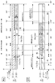
図6は、本発明の第1実施形態を示す固定スクロール16および旋回スクロール20におけるラップ壁体18,22の展開図である。この図6中に表示されている角度数値は、それぞれ図3に示す固定ラップ壁体18および旋回ラップ壁体22における同数値の位置に合致している。
各ラップ壁体18,22は、その径方向内周側の面を「腹面」、径方向外周側の面を「背面」と呼ぶ。
次に、本発明の第1実施形態について説明する。
図6は、本発明の第1実施形態を示す固定スクロール16および旋回スクロール20におけるラップ壁体18,22の展開図である。この図6中に表示されている角度数値は、それぞれ図3に示す固定ラップ壁体18および旋回ラップ壁体22における同数値の位置に合致している。
各ラップ壁体18,22は、その径方向内周側の面を「腹面」、径方向外周側の面を「背面」と呼ぶ。
ラップ壁体18,22の腹面は、その周方向に沿って、始点SPから0°までの非インボリュート区間と、0°から450°までの区間A1と、450°から630°までの区間A2と、630°から900°の手前の終点EPまでの区間A3との3区間に分けることができる。これら3つの区間A1,A2,A3における歯底面17a,21aから歯先面18a,22aまでのラップ高さは、それぞれH1,H2,H3となっており、その大小関係はH1<H2<H3となっている。
ラップ壁体18,22の背面は、その周方向に沿って、始点SPから0°までの非インボリュート区間と、0°から270°までの区間B1と、270°から450°までの区間B2と、450°から720°の手前の点P1までの区間B3と、点P1から900°の手前の終点EPまでの区間B4の4区間に分けることができる。区間B4には相対するラップ壁体の腹面が重なることがない。これら4つの区間B1,B2,B3,B4における歯底面17a,21aから歯先面18a,22aまでのラップ高さは、それぞれH1,H2,H3となっており、その大小関係はH1<H2<H3となっている。
この固定ラップ壁体18および旋回ラップ壁体22は、その歯先段差部TSよりも渦巻き方向内周側の区間の有効渦巻長さ、即ち始点SPから0°までの非インボリュート区間を除いた、腹面においては区間A1、背面においては区間B1+B2の渦巻長さが360°以上とされている。つまり、固定ラップ壁体18と旋回ラップ壁体22とが組み合わされた時に、両方のラップ壁体18,22の、腹面の区間A1と、背面の区間B1+B2とが、互いにその渦巻方向に1周以上重なるようになっている。
これらのラップ壁体18,22において、その歯底段差部BSよりも渦巻き方向外周側の歯底面17a,21aに隣接する腹面側の区間A3および背面側の区間B2,B3の各面は、被圧縮流体である冷媒の圧縮に悪影響を及ぼさない程度に、本来の腹面および背面の面プロフィールよりも僅かに内側に後退している。換言すれば、ラップ壁体18,22の厚さが従来よりも薄くされている。図3中には面を後退させる範囲が記号×××で示され、図6中には面を後退させる範囲が網掛け表示されている。
なお、背面側の区間B4も内側に後退させてもよいが、この面には相対する渦巻き状ラップ壁体18,22が重なることがない(接触する懸念がない)ため、面を後退させなくてもよい。
この後退量は、その最大値をδ、旋回スクロール20の旋回半径をρとした場合に、δ/ρ≦0.01の範囲内となるように設定される。具体的な数値としては、例えば100μm以下、好ましくは10~20μm程度とするのがよい。面を後退させる方法としては、最初から後退された形状で製作するか、あるいは後退されていないラップ壁体18,22を後加工することが考えられる。後加工する方法としては、研摩や切削等の機械的な方法、あるいはエッチング等の化学的な方法が考えられる。
なお、背面側の区間B4も内側に後退させてもよいが、この面には相対する渦巻き状ラップ壁体18,22が重なることがない(接触する懸念がない)ため、面を後退させなくてもよい。
この後退量は、その最大値をδ、旋回スクロール20の旋回半径をρとした場合に、δ/ρ≦0.01の範囲内となるように設定される。具体的な数値としては、例えば100μm以下、好ましくは10~20μm程度とするのがよい。面を後退させる方法としては、最初から後退された形状で製作するか、あるいは後退されていないラップ壁体18,22を後加工することが考えられる。後加工する方法としては、研摩や切削等の機械的な方法、あるいはエッチング等の化学的な方法が考えられる。
固定スクロール16と旋回スクロール20は以上のように構成されている。これによれば、ラップ壁体18,22のラップ高さが高くなっている区間、即ち歯底段差部BSよりも渦巻き方向外周側の区間A3(腹面側)およびB2,B3(背面側)において、ラップ壁体18,22の両面が本来の腹面の面プロフィールよりも内側に後退しているため、ラップ高さH2,H3が高い渦巻き方向外周側の区間においては、固定ラップ壁体18と旋回ラップ壁体22とが接触することがない。したがって、ラップ壁体18,22同士の接触による破損を未然に防止することができる。
上記の構成では、歯先段差部TSよりも渦巻き方向内周側の区間A1(腹面側)およびB1,B2(背面側)における渦巻長さが360°以上あり、この区間においてはラップ壁体18,22の腹面および背面の両面が内側に後退せずに本来の側面プロフィールを保ったままとされる。
このため、段付きスクロール圧縮機1の作動時には、この渦巻き方向内周側の区間A1,B1,B2においてのみラップ壁体18,22同士が2点で接触し、これによって固定スクロール16に対する旋回スクロール20の旋回軌道が確定される。
したがって、歯底段差部BSよりも渦巻き方向外周側の区間A3,B2,B3においてラップ壁体18,22の腹面および背面を内側に後退させても、この後退させた分だけ旋回スクロール20がその端板21の面方向に移動してしまうことがなく、ラップ壁体18,22同士の接触による破損を防止することができる。
このため、段付きスクロール圧縮機1の作動時には、この渦巻き方向内周側の区間A1,B1,B2においてのみラップ壁体18,22同士が2点で接触し、これによって固定スクロール16に対する旋回スクロール20の旋回軌道が確定される。
したがって、歯底段差部BSよりも渦巻き方向外周側の区間A3,B2,B3においてラップ壁体18,22の腹面および背面を内側に後退させても、この後退させた分だけ旋回スクロール20がその端板21の面方向に移動してしまうことがなく、ラップ壁体18,22同士の接触による破損を防止することができる。
ラップ壁体18,22の腹面および背面を内側に後退させる量は、冷媒の圧縮に悪影響を及ぼさない程度、例えば100μm程度以下に設定されているため、段付きスクロール圧縮機1の圧縮漏れを最小限に抑えて圧縮性能の低下を防止しながら、ラップ壁体18,22の破損を防止し、段付きスクロール圧縮機1の耐久性と信頼性を高めることができる。最も圧縮圧力が高くなる渦巻方向内周側の区間A1,B1においてはラップ壁体18,22の腹面および背面が後退しておらず、両方のラップ壁体18,22の間に隙間が発生しないため、この点でも冷媒の圧縮漏れを防止することができる。
ラップ壁体18,22の腹面および背面の後退量は、その最大値をδ、旋回スクロール20の旋回半径をρとした場合に、δ/ρ≦0.01の範囲内となるように最大値δが設定されている。このため、各種の大きさの段付きスクロール圧縮機において、ラップ壁体18,22の破損防止と、圧縮漏れによる性能低下の抑制とを両立させることができる。
ラップ壁体18,22の腹面および背面の後退は、必ずしも腹面および背面の高さ方向全域に亘って均等に行うようにする必要はなく、ラップ壁体18,22の根元側から先端側に向かって後退量が大きくなるようにしてもよい。例えば、図7に示すように、ラップ壁体18,22の縦断面形状が根元側から先端側に向かって細くなるテーパー状にしたり、図8に示すように、ラップ壁体18,22の縦断面形状が根元側から先端側に向かって段階的に細くなるようにしたりすることが考えられる。
こうすれば、ラップ壁体18,22の根元側における厚さ寸法を減少させて強度を損なわせてしまうことなく、先端側においてラップ壁体18,22同士が接触することを防止し、ラップ壁体18,22の破損を防ぐことができる。相対する固定ラップ壁体18と旋回ラップ壁体22とが、共に同じテーパー断面形状、あるいは段付き断面形状であれば、両方のラップ壁体18,22の断面形状が等しく、互いに逆向きであるため、ラップ壁体18,22間の噛み合い間隔を必要最小限にして冷媒の漏れを防止することができる。
[第2実施形態]
次に、本発明の第2実施形態について説明する。
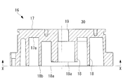
図9は本発明の第2実施形態に係る固定スクロール16の拡大縦断面図であり、図10は固定スクロール16の下面図である。また、図11は、固定スクロールと旋回スクロールとが組み合わされた図である。さらに、図12は、本発明の第2実施形態を示す固定スクロールおよび旋回スクロールにおけるラップ壁体18,22の展開図である。ここに示す固定スクロール16と旋回スクロール20は、そのラップ壁体18,22の巻き数(角度数値)が第1実施形態のものと異なるだけであり、ラップ壁体18,22の高さや各部の基本的な構造は同様である。したがって、同一構成の各部には同一の符号を付して説明を省略する。
次に、本発明の第2実施形態について説明する。
図9は本発明の第2実施形態に係る固定スクロール16の拡大縦断面図であり、図10は固定スクロール16の下面図である。また、図11は、固定スクロールと旋回スクロールとが組み合わされた図である。さらに、図12は、本発明の第2実施形態を示す固定スクロールおよび旋回スクロールにおけるラップ壁体18,22の展開図である。ここに示す固定スクロール16と旋回スクロール20は、そのラップ壁体18,22の巻き数(角度数値)が第1実施形態のものと異なるだけであり、ラップ壁体18,22の高さや各部の基本的な構造は同様である。したがって、同一構成の各部には同一の符号を付して説明を省略する。
ラップ壁体18,22の腹面は、その周方向に沿って、始点SPから0°までの非インボリュート区間と、0°から歯先段差部TS(点P1)までの区間A1と、歯先段差部TS(P1)から歯底段差部BS(点P2)までの区間A2と、歯底段差部BS(P2)から終点EPまでの区間A3との3区間に分けることができる。これら3つの区間A1,A2,A3における歯底面17a,21aから歯先面18a,22aまでのラップ高さは、それぞれH1,H2,H3となっており、その大小関係はH1<H2<H3となっている。
ラップ壁体18,22の背面は、その周方向に沿って、始点SPから0°までの非インボリュート区間と、0°から歯底段差部BSまでの区間B1と、底段差部BSから歯先段差部TS(点P1)までの区間B2と、歯先段差部TS(P1)から終点EPまでの区間B3との3区間に分けることができる。これら3つの区間B1,B2,B3における歯底面17a,21aから歯先面18a,22aまでのラップ高さも、それぞれH1,H2,H3となっており、その大小関係はH1<H2<H3となっている。
この固定ラップ壁体18および旋回ラップ壁体22は、その歯先段差部TSよりも渦巻き方向内周側の区間の有効渦巻長さ、即ち始点SPから0°までの非インボリュート区間を除いた、0°から歯先段差部TSまでの区間B1の渦巻長さが360°未満とされている。つまり、固定ラップ壁体18と旋回ラップ壁体22とが組み合わされた時に、各々のラップ壁体18,22の内周側の区間A1とB1+B2とが重なる周長が1周に満たず、全体の巻き数も少なくなっており、その分、旋回スクロールの旋回半径ρが大きく設定されている。
このように、歯先段差部TSよりも渦巻き方向内周側の区間A1,B1+B2の渦巻長さが360°に満たない場合は、歯底段差部BSよりも渦巻き方向外周側の歯底面17a,21aに隣接する渦巻き状ラップ壁体18,22の腹面のみについて、冷媒の圧縮に悪影響を及ぼさない程度に、本来の側面プロフィールよりも僅かに内側に後退させる。即ち、ラップ壁体18,22の腹面側の区間A3について面が後退されている。図10中には面を後退させる範囲が記号×××で示され、図12中には面を後退させる範囲が網掛け表示されている。その後退量の設定条件等は第1実施形態と同様である。
このようにすれば、ラップ壁体18,22のラップ高さが最も高くなっている区間、即ち歯底段差部BSよりも渦巻き方向外周側の区間A3において、ラップ壁体18,22の腹面が本来の側面プロフィールよりも内側に後退しているため、ラップ高さH3が最も高く破損のリスクが大きい渦巻き方向最外周側の区間A3,B3においては、ラップ壁体18,22同士が接触することがなく、ラップ壁体18,22同士の接触による破損を未然に防止することができる。
上記の構成では、腹面側における歯底段差部BSよりも渦巻き方向内周側の区間A1+A2と、背面側における全区間B1+B2+B3において、渦巻き状ラップ壁体(18,22)の側面が内側に後退せずに本来の側面プロフィールを保ったままとされている。
本実施形態では、歯先段差部TSよりも渦巻き方向内周側の区間、即ち腹面側の区間A1と、背面側の区間B1+B2は、いずれも渦巻長さが360°未満であるが、腹面側においては、歯先段差部TSと歯底段差部BS(点P2)との間の区間A2を合わせると渦巻長さが360°を超える。また、背面側においては、区間B3における点P1から点P2に相当する区間までを合わせると渦巻長さが360°を超える(図11も参照)。
このため、段付きスクロール圧縮機1の作動時には、図11に示すように、各ラップ壁体18,22における0°から点P2までの区間(網掛け表示した範囲)が互いに360°を越え、この両区間内のいずれかの位置において、ラップ壁体18,22同士がT1,T2の2点で接触し、これによって固定スクロール16に対する旋回スクロール20の旋回軌道が確定される。
したがって、歯底段差部BSよりも渦巻き方向外周側の区間A3、即ちラップ壁体18,22のラップ高さH3が最も高い区間においてラップ壁体18,22の腹面を内側に後退させても、この後退させた分だけ旋回スクロール20がその端板21の面方向に移動してしまうことがなく、ラップ壁体18,22同士の接触による破損を防止することができる。
本構成および設計方法によれば、ラップ壁体18,22の全周のうち、ラップ高さが最も高い最外周側の区間A3において腹面側のみが後退され、その他の区間A1,A2および背面側の区間B1,B2,B3については腹面側も背面側も後退されていない。このため、第1実施形態の構成に比べて冷媒の圧縮漏れを抑制することができ、特にラップ壁体18,22の巻き数が少ない段付きスクロール圧縮機における圧縮効率の低下を防止することができる。
ところで、図13に示すように、歯底段差部BSの位置において、ラップ壁体18,22の腹面の後退量を、渦巻き方向外周側から内周側に向かって漸減させるようにしてもよい。これにより、端板17,21に歯底段差部BSを加工形成する際に発生しやすいバリに、相対するスクロール16,20のラップ壁体18,22が干渉することによる騒音の発生を防止することができる。
以上に説明したように、本発明に係る段付きスクロール圧縮機およびその設計方法によれば、ラップ高さが高い区間における渦巻き状ラップ壁体の破損を防止し、耐久性と信頼性を高めるとともに、圧縮漏れを最小限に抑えて圧縮性能の低下を防止することができる。
なお、本発明は上記実施形態の構成のみに限定されるものではなく、適宜変更や改良を加えることができ、このように変更や改良を加えた実施形態も本発明の権利範囲に含まれるものとする。
例えば、段付きスクロール圧縮機1の内部構成や、縦型、横型等の姿勢配置、用途、被圧縮流体の種類、さらには固定スクロール16や旋回スクロール20の詳細な形状等に至るまで、必ずしも上記実施形態に沿うものである必要はない。
例えば、段付きスクロール圧縮機1の内部構成や、縦型、横型等の姿勢配置、用途、被圧縮流体の種類、さらには固定スクロール16や旋回スクロール20の詳細な形状等に至るまで、必ずしも上記実施形態に沿うものである必要はない。
また、本実施形態では、固定スクロール16と旋回スクロール20の両方の歯底面17a,21aに歯底段差部BSが設けられ、両方の歯先面18a,22aに歯先段差部TSが設けられた機種について説明したが、一方のスクロールに歯底段差部BSのみ、他方のスクロールに歯先段差部TSのみが設けられた機種についても本発明を適用することができる。
なお、本実施形態では、固定スクロール16の固定ラップ壁体18と、旋回スクロール20の旋回ラップ壁体22との両方について、その腹面や背面を面後退させているが、どちらか一方のスクロールのラップ壁体についてのみ面後退させることも考えられる。この場合は、ラップ壁体の腹面または背面のいずれかについてのみ、相対するラップとの接触が防止される。
1 スクロール圧縮機
16 固定スクロール
17 固定端板(端板)
17a,21a 歯底面
18 固定ラップ壁体(渦巻き状ラップ壁体)
18a,22a 歯先面
20 旋回スクロール
21 旋回端板(端板)
22 旋回ラップ壁体(渦巻き状ラップ壁体)
24 圧縮室
BS 歯底段差部
TS 歯先段差部
ρ 旋回スクロールの旋回半径
16 固定スクロール
17 固定端板(端板)
17a,21a 歯底面
18 固定ラップ壁体(渦巻き状ラップ壁体)
18a,22a 歯先面
20 旋回スクロール
21 旋回端板(端板)
22 旋回ラップ壁体(渦巻き状ラップ壁体)
24 圧縮室
BS 歯底段差部
TS 歯先段差部
ρ 旋回スクロールの旋回半径
Claims (11)
- それぞれの端板の一側面に渦巻き状ラップ壁体を立設させた固定スクロールおよび旋回スクロールが、互いの前記渦巻き状ラップ壁体を噛み合わせることにより被圧縮流体を圧縮する一対の圧縮室を形成し、
前記固定スクロールと前記旋回スクロールの少なくとも一方の前記端板の前記一側面には、その歯底面の高さが前記渦巻き状ラップ壁体の渦巻き方向外周側から内周側に向かって高くなる歯底段差部が設けられ、
前記歯底段差部に対応する他方の前記スクロールの前記渦巻き状ラップ壁体には、その歯先面の高さが渦巻き方向外周側から内周側に向かって低くなる歯先段差部が設けられた段付きスクロール圧縮機であって、
前記固定スクロールおよび前記旋回スクロールの少なくとも一方は、その前記歯底段差部よりも渦巻き方向外周側の歯底面に隣接し、且つ、少なくとも相対する前記渦巻き状ラップ壁体と重なる範囲における前記渦巻き状ラップ壁体の腹面のみが、その本来の側面プロフィールよりも内側に後退している段付きスクロール圧縮機。 - それぞれの端板の一側面に渦巻き状ラップ壁体を立設させた固定スクロールおよび旋回スクロールが、互いの前記渦巻き状ラップ壁体を噛み合わせることにより被圧縮流体を圧縮する一対の圧縮室を形成し、
前記固定スクロールと前記旋回スクロールの少なくとも一方の前記端板の前記一側面には、その歯底面の高さが前記渦巻き状ラップ壁体の渦巻き方向外周側から内周側に向かって高くなる歯底段差部が設けられ、
前記歯底段差部に対応する他方の前記スクロールの前記渦巻き状ラップ壁体には、その歯先面の高さが渦巻き方向外周側から内周側に向かって低くなる歯先段差部が設けられた段付きスクロール圧縮機であって、
前記固定スクロールおよび前記旋回スクロールの少なくとも一方は、その前記歯底段差部よりも渦巻き方向外周側の歯底面に隣接する前記渦巻き状ラップ壁体の腹面および背面が、その本来の側面プロフィールよりも内側に後退している段付きスクロール圧縮機。 - 前記渦巻き状ラップ壁体における、非インボリュート区間を除いた、前記歯先段差部よりも渦巻き方向内周側の区間の渦巻長さが360°未満である請求項1に記載の段付きスクロール圧縮機。
- 前記渦巻き状ラップ壁体における、非インボリュート区間を除いた、前記歯先段差部よりも渦巻き方向内周側の区間の渦巻長さが360°以上である請求項2に記載の段付きスクロール圧縮機。
- 前記渦巻き状ラップ壁体の前記腹面および前記背面の後退量の最大値をδ、前記旋回スクロールの旋回半径をρとした場合に、δ/ρ≦0.01の範囲内となるように前記後退量の最大値δが設定されている請求項1から4のいずれかに記載の段付きスクロール圧縮機。
- 前記歯底段差部の位置にて前記渦巻き状ラップ壁体の前記腹面および前記背面の後退量が渦巻き方向外周側から内周側に向かって漸減している請求項2から4のいずれかに記載の段付きスクロール圧縮機。
- 前記渦巻き状ラップ壁体の前記腹面および前背面の後退量は、前記渦巻き状ラップ壁体の根元側から先端側に向かって大きくなっている請求項1から4のいずれかに記載の段付きスクロール圧縮機。
- それぞれの端板の一側面に渦巻き状ラップ壁体を立設させた固定スクロールおよび旋回スクロールが、互いの前記渦巻き状ラップ壁体を噛み合わせることにより被圧縮流体を圧縮する一対の圧縮室を形成し、
前記固定スクロールと前記旋回スクロールの少なくとも一方の前記端板の前記一側面には、その歯底面の高さが前記渦巻き状ラップ壁体の渦巻き方向外周側から内周側に向かって高くなる歯底段差部が設けられ、
前記歯底段差部に対応する他方の前記スクロールの前記渦巻き状ラップ壁体には、その歯先面の高さが渦巻き方向外周側から内周側に向かって低くなる歯先段差部が設けられた段付きスクロール圧縮機の設計方法であって、
前記固定スクロールおよび前記旋回スクロールの少なくとも一方について、その前記歯底段差部よりも渦巻き方向外周側の歯底面に隣接し、且つ、少なくとも相対する前記渦巻き状ラップ壁体と重なる範囲における前記渦巻き状ラップ壁体の腹面のみを、その本来の側面プロフィールよりも内側に後退させる段付きスクロール圧縮機の設計方法。 - それぞれの端板の一側面に渦巻き状ラップ壁体を立設させた固定スクロールおよび旋回スクロールが、互いの前記渦巻き状ラップ壁体を噛み合わせることにより被圧縮流体を圧縮する一対の圧縮室を形成し、
前記固定スクロールと前記旋回スクロールの少なくとも一方の前記端板の前記一側面には、その歯底面の高さが前記渦巻き状ラップ壁体の渦巻き方向外周側から内周側に向かって高くなる歯底段差部が設けられ、
前記歯底段差部に対応する他方の前記スクロールの前記渦巻き状ラップ壁体には、その歯先面の高さが渦巻き方向外周側から内周側に向かって低くなる歯先段差部が設けられた段付きスクロール圧縮機の設計方法であって、
前記固定スクロールおよび前記旋回スクロールの少なくとも一方について、その前記歯底段差部よりも渦巻き方向外周側の歯底面に隣接する前記渦巻き状ラップ壁体の腹面および背面を、その本来の側面プロフィールよりも内側に後退させる段付きスクロール圧縮機の設計方法。 - 前記渦巻き状ラップ壁体における、非インボリュート区間を除いた、前記歯先段差部よりも渦巻き方向内周側の区間の渦巻長さを360°未満とする請求項8に記載の段付きスクロール圧縮機の設計方法。
- 前記渦巻き状ラップ壁体における、非インボリュート区間を除いた、前記歯先段差部よりも渦巻き方向内周側の区間の渦巻長さを360°以上とする請求項9に記載の段付きスクロール圧縮機の設計方法。
Priority Applications (2)
| Application Number | Priority Date | Filing Date | Title |
|---|---|---|---|
| EP17827398.3A EP3441614A4 (en) | 2016-07-15 | 2017-06-26 | PRESCRIBED SCROLL COMPRESSORS AND DESIGN PROCESS THEREFOR |
| CN201780026502.3A CN109072912B (zh) | 2016-07-15 | 2017-06-26 | 阶梯式涡旋压缩机及其设计方法 |
Applications Claiming Priority (2)
| Application Number | Priority Date | Filing Date | Title |
|---|---|---|---|
| JP2016-140551 | 2016-07-15 | ||
| JP2016140551A JP6758969B2 (ja) | 2016-07-15 | 2016-07-15 | 段付きスクロール圧縮機およびその設計方法 |
Publications (1)
| Publication Number | Publication Date |
|---|---|
| WO2018012268A1 true WO2018012268A1 (ja) | 2018-01-18 |
Family
ID=60952056
Family Applications (1)
| Application Number | Title | Priority Date | Filing Date |
|---|---|---|---|
| PCT/JP2017/023425 Ceased WO2018012268A1 (ja) | 2016-07-15 | 2017-06-26 | 段付きスクロール圧縮機およびその設計方法 |
Country Status (4)
| Country | Link |
|---|---|
| EP (1) | EP3441614A4 (ja) |
| JP (1) | JP6758969B2 (ja) |
| CN (1) | CN109072912B (ja) |
| WO (1) | WO2018012268A1 (ja) |
Cited By (2)
| Publication number | Priority date | Publication date | Assignee | Title |
|---|---|---|---|---|
| WO2020234988A1 (ja) * | 2019-05-21 | 2020-11-26 | 三菱電機株式会社 | スクロール圧縮機 |
| EP3754197A4 (en) * | 2018-02-21 | 2021-07-28 | Mitsubishi Heavy Industries Thermal Systems, Ltd. | SPIRAL FLUID MACHINE AND PROCESSING PROCESS FOR A SPIRAL ELEMENT |
Families Citing this family (2)
| Publication number | Priority date | Publication date | Assignee | Title |
|---|---|---|---|---|
| JP6599099B2 (ja) * | 2014-12-15 | 2019-10-30 | 三菱重工サーマルシステムズ株式会社 | スクロール流体機械 |
| DE102024115790A1 (de) * | 2024-06-06 | 2025-12-11 | Zf Cv Systems Global Gmbh | Spiralverdichter |
Citations (5)
| Publication number | Priority date | Publication date | Assignee | Title |
|---|---|---|---|---|
| JP2000170671A (ja) * | 1998-09-29 | 2000-06-20 | Tokico Ltd | スクロ―ル式流体機械 |
| JP2007224775A (ja) | 2006-02-22 | 2007-09-06 | Mitsubishi Heavy Ind Ltd | スクロール圧縮機 |
| JP2007255191A (ja) * | 2006-03-20 | 2007-10-04 | Mitsubishi Heavy Ind Ltd | スクロール圧縮機 |
| JP2011074884A (ja) * | 2009-10-01 | 2011-04-14 | Mitsubishi Heavy Ind Ltd | スクロール流体機械 |
| JP2014152748A (ja) * | 2013-02-13 | 2014-08-25 | Panasonic Corp | スクロール圧縮機 |
Family Cites Families (6)
| Publication number | Priority date | Publication date | Assignee | Title |
|---|---|---|---|---|
| DE3801156C2 (de) * | 1987-01-24 | 1998-09-24 | Volkswagen Ag | Spiralverdichter |
| JP2971739B2 (ja) * | 1994-06-20 | 1999-11-08 | トキコ株式会社 | スクロール式流体機械 |
| JP4658381B2 (ja) * | 2001-05-31 | 2011-03-23 | 三菱重工業株式会社 | スクロール圧縮機 |
| CN101484704B (zh) * | 2007-01-30 | 2013-05-22 | 三菱重工业株式会社 | 涡旋压缩机 |
| JP5622473B2 (ja) * | 2010-07-30 | 2014-11-12 | 三菱重工業株式会社 | スクロール圧縮機 |
| JP5888897B2 (ja) * | 2011-08-05 | 2016-03-22 | 三菱重工業株式会社 | スクロール部材及びスクロール型流体機械 |
-
2016
- 2016-07-15 JP JP2016140551A patent/JP6758969B2/ja active Active
-
2017
- 2017-06-26 CN CN201780026502.3A patent/CN109072912B/zh active Active
- 2017-06-26 WO PCT/JP2017/023425 patent/WO2018012268A1/ja not_active Ceased
- 2017-06-26 EP EP17827398.3A patent/EP3441614A4/en not_active Withdrawn
Patent Citations (5)
| Publication number | Priority date | Publication date | Assignee | Title |
|---|---|---|---|---|
| JP2000170671A (ja) * | 1998-09-29 | 2000-06-20 | Tokico Ltd | スクロ―ル式流体機械 |
| JP2007224775A (ja) | 2006-02-22 | 2007-09-06 | Mitsubishi Heavy Ind Ltd | スクロール圧縮機 |
| JP2007255191A (ja) * | 2006-03-20 | 2007-10-04 | Mitsubishi Heavy Ind Ltd | スクロール圧縮機 |
| JP2011074884A (ja) * | 2009-10-01 | 2011-04-14 | Mitsubishi Heavy Ind Ltd | スクロール流体機械 |
| JP2014152748A (ja) * | 2013-02-13 | 2014-08-25 | Panasonic Corp | スクロール圧縮機 |
Non-Patent Citations (1)
| Title |
|---|
| See also references of EP3441614A4 * |
Cited By (3)
| Publication number | Priority date | Publication date | Assignee | Title |
|---|---|---|---|---|
| EP3754197A4 (en) * | 2018-02-21 | 2021-07-28 | Mitsubishi Heavy Industries Thermal Systems, Ltd. | SPIRAL FLUID MACHINE AND PROCESSING PROCESS FOR A SPIRAL ELEMENT |
| WO2020234988A1 (ja) * | 2019-05-21 | 2020-11-26 | 三菱電機株式会社 | スクロール圧縮機 |
| JPWO2020234988A1 (ja) * | 2019-05-21 | 2021-10-21 | 三菱電機株式会社 | スクロール圧縮機 |
Also Published As
| Publication number | Publication date |
|---|---|
| EP3441614A1 (en) | 2019-02-13 |
| CN109072912A (zh) | 2018-12-21 |
| EP3441614A4 (en) | 2019-06-05 |
| CN109072912B (zh) | 2021-05-07 |
| JP2018009553A (ja) | 2018-01-18 |
| JP6758969B2 (ja) | 2020-09-23 |
Similar Documents
| Publication | Publication Date | Title |
|---|---|---|
| JP6180860B2 (ja) | スクロール圧縮機 | |
| JP5472424B2 (ja) | スクロール圧縮機 | |
| JP5851851B2 (ja) | スクロール圧縮機 | |
| KR102051095B1 (ko) | 스크롤 압축기 | |
| JP5182446B1 (ja) | スクロール圧縮機 | |
| KR101277213B1 (ko) | 바이패스 홀을 갖는 스크롤 압축기 | |
| JP5888897B2 (ja) | スクロール部材及びスクロール型流体機械 | |
| JP2003269346A (ja) | スクロール型流体機械 | |
| JP5879532B2 (ja) | スクロール型圧縮機 | |
| JP6758969B2 (ja) | 段付きスクロール圧縮機およびその設計方法 | |
| JP2004183497A (ja) | スクロール式流体機械 | |
| JP2011074884A (ja) | スクロール流体機械 | |
| JP5195774B2 (ja) | スクロール圧縮機 | |
| JP6532713B2 (ja) | スクロール圧縮機 | |
| JP2008133763A (ja) | スクリュー流体機械 | |
| JP2023140880A (ja) | ルーツポンプ | |
| CN107683372B (zh) | 涡旋式流体机械 | |
| JP7616859B2 (ja) | スクリュー圧縮機及びスクリューロータ | |
| WO2016121658A1 (ja) | スクロール流体機械 | |
| WO2013108866A1 (ja) | チップシールおよびそれを用いたスクロール圧縮機 | |
| JP5889168B2 (ja) | スクロール圧縮機 | |
| JP6873763B2 (ja) | スクリュー流体機械 | |
| JP2016173069A (ja) | スクロール圧縮機 | |
| KR102859738B1 (ko) | 스크롤 압축기 | |
| JP5440202B2 (ja) | スクロール圧縮機の製造方法 |
Legal Events
| Date | Code | Title | Description |
|---|---|---|---|
| WWE | Wipo information: entry into national phase |
Ref document number: 2017827398 Country of ref document: EP |
|
| ENP | Entry into the national phase |
Ref document number: 2017827398 Country of ref document: EP Effective date: 20181106 |
|
| 121 | Ep: the epo has been informed by wipo that ep was designated in this application |
Ref document number: 17827398 Country of ref document: EP Kind code of ref document: A1 |
|
| NENP | Non-entry into the national phase |
Ref country code: DE |