WO2018016085A1 - ハイブリッド車両の制御装置および制御方法 - Google Patents
ハイブリッド車両の制御装置および制御方法 Download PDFInfo
- Publication number
- WO2018016085A1 WO2018016085A1 PCT/JP2016/076713 JP2016076713W WO2018016085A1 WO 2018016085 A1 WO2018016085 A1 WO 2018016085A1 JP 2016076713 W JP2016076713 W JP 2016076713W WO 2018016085 A1 WO2018016085 A1 WO 2018016085A1
- Authority
- WO
- WIPO (PCT)
- Prior art keywords
- motor generator
- internal combustion
- combustion engine
- assist
- control device
- Prior art date
- Legal status (The legal status is an assumption and is not a legal conclusion. Google has not performed a legal analysis and makes no representation as to the accuracy of the status listed.)
- Ceased
Links
Images


Classifications
-
- B—PERFORMING OPERATIONS; TRANSPORTING
- B60—VEHICLES IN GENERAL
- B60K—ARRANGEMENT OR MOUNTING OF PROPULSION UNITS OR OF TRANSMISSIONS IN VEHICLES; ARRANGEMENT OR MOUNTING OF PLURAL DIVERSE PRIME-MOVERS IN VEHICLES; AUXILIARY DRIVES FOR VEHICLES; INSTRUMENTATION OR DASHBOARDS FOR VEHICLES; ARRANGEMENTS IN CONNECTION WITH COOLING, AIR INTAKE, GAS EXHAUST OR FUEL SUPPLY OF PROPULSION UNITS IN VEHICLES
- B60K6/00—Arrangement or mounting of plural diverse prime-movers for mutual or common propulsion, e.g. hybrid propulsion systems comprising electric motors and internal combustion engines
- B60K6/20—Arrangement or mounting of plural diverse prime-movers for mutual or common propulsion, e.g. hybrid propulsion systems comprising electric motors and internal combustion engines the prime-movers consisting of electric motors and internal combustion engines, e.g. HEVs
- B60K6/42—Arrangement or mounting of plural diverse prime-movers for mutual or common propulsion, e.g. hybrid propulsion systems comprising electric motors and internal combustion engines the prime-movers consisting of electric motors and internal combustion engines, e.g. HEVs characterised by the architecture of the hybrid electric vehicle
- B60K6/48—Parallel type
- B60K6/485—Motor-assist type
-
- B—PERFORMING OPERATIONS; TRANSPORTING
- B60—VEHICLES IN GENERAL
- B60L—PROPULSION OF ELECTRICALLY-PROPELLED VEHICLES; SUPPLYING ELECTRIC POWER FOR AUXILIARY EQUIPMENT OF ELECTRICALLY-PROPELLED VEHICLES; ELECTRODYNAMIC BRAKE SYSTEMS FOR VEHICLES IN GENERAL; MAGNETIC SUSPENSION OR LEVITATION FOR VEHICLES; MONITORING OPERATING VARIABLES OF ELECTRICALLY-PROPELLED VEHICLES; ELECTRIC SAFETY DEVICES FOR ELECTRICALLY-PROPELLED VEHICLES
- B60L50/00—Electric propulsion with power supplied within the vehicle
- B60L50/10—Electric propulsion with power supplied within the vehicle using propulsion power supplied by engine-driven generators, e.g. generators driven by combustion engines
- B60L50/13—Electric propulsion with power supplied within the vehicle using propulsion power supplied by engine-driven generators, e.g. generators driven by combustion engines using AC generators and AC motors
-
- B—PERFORMING OPERATIONS; TRANSPORTING
- B60—VEHICLES IN GENERAL
- B60L—PROPULSION OF ELECTRICALLY-PROPELLED VEHICLES; SUPPLYING ELECTRIC POWER FOR AUXILIARY EQUIPMENT OF ELECTRICALLY-PROPELLED VEHICLES; ELECTRODYNAMIC BRAKE SYSTEMS FOR VEHICLES IN GENERAL; MAGNETIC SUSPENSION OR LEVITATION FOR VEHICLES; MONITORING OPERATING VARIABLES OF ELECTRICALLY-PROPELLED VEHICLES; ELECTRIC SAFETY DEVICES FOR ELECTRICALLY-PROPELLED VEHICLES
- B60L50/00—Electric propulsion with power supplied within the vehicle
- B60L50/10—Electric propulsion with power supplied within the vehicle using propulsion power supplied by engine-driven generators, e.g. generators driven by combustion engines
- B60L50/16—Electric propulsion with power supplied within the vehicle using propulsion power supplied by engine-driven generators, e.g. generators driven by combustion engines with provision for separate direct mechanical propulsion
-
- B—PERFORMING OPERATIONS; TRANSPORTING
- B60—VEHICLES IN GENERAL
- B60W—CONJOINT CONTROL OF VEHICLE SUB-UNITS OF DIFFERENT TYPE OR DIFFERENT FUNCTION; CONTROL SYSTEMS SPECIALLY ADAPTED FOR HYBRID VEHICLES; ROAD VEHICLE DRIVE CONTROL SYSTEMS FOR PURPOSES NOT RELATED TO THE CONTROL OF A PARTICULAR SUB-UNIT
- B60W10/00—Conjoint control of vehicle sub-units of different type or different function
- B60W10/04—Conjoint control of vehicle sub-units of different type or different function including control of propulsion units
- B60W10/06—Conjoint control of vehicle sub-units of different type or different function including control of propulsion units including control of combustion engines
-
- B—PERFORMING OPERATIONS; TRANSPORTING
- B60—VEHICLES IN GENERAL
- B60W—CONJOINT CONTROL OF VEHICLE SUB-UNITS OF DIFFERENT TYPE OR DIFFERENT FUNCTION; CONTROL SYSTEMS SPECIALLY ADAPTED FOR HYBRID VEHICLES; ROAD VEHICLE DRIVE CONTROL SYSTEMS FOR PURPOSES NOT RELATED TO THE CONTROL OF A PARTICULAR SUB-UNIT
- B60W10/00—Conjoint control of vehicle sub-units of different type or different function
- B60W10/04—Conjoint control of vehicle sub-units of different type or different function including control of propulsion units
- B60W10/08—Conjoint control of vehicle sub-units of different type or different function including control of propulsion units including control of electric propulsion units, e.g. motors or generators
-
- B—PERFORMING OPERATIONS; TRANSPORTING
- B60—VEHICLES IN GENERAL
- B60W—CONJOINT CONTROL OF VEHICLE SUB-UNITS OF DIFFERENT TYPE OR DIFFERENT FUNCTION; CONTROL SYSTEMS SPECIALLY ADAPTED FOR HYBRID VEHICLES; ROAD VEHICLE DRIVE CONTROL SYSTEMS FOR PURPOSES NOT RELATED TO THE CONTROL OF A PARTICULAR SUB-UNIT
- B60W10/00—Conjoint control of vehicle sub-units of different type or different function
- B60W10/24—Conjoint control of vehicle sub-units of different type or different function including control of energy storage means
- B60W10/26—Conjoint control of vehicle sub-units of different type or different function including control of energy storage means for electrical energy, e.g. batteries or capacitors
-
- B—PERFORMING OPERATIONS; TRANSPORTING
- B60—VEHICLES IN GENERAL
- B60W—CONJOINT CONTROL OF VEHICLE SUB-UNITS OF DIFFERENT TYPE OR DIFFERENT FUNCTION; CONTROL SYSTEMS SPECIALLY ADAPTED FOR HYBRID VEHICLES; ROAD VEHICLE DRIVE CONTROL SYSTEMS FOR PURPOSES NOT RELATED TO THE CONTROL OF A PARTICULAR SUB-UNIT
- B60W10/00—Conjoint control of vehicle sub-units of different type or different function
- B60W10/30—Conjoint control of vehicle sub-units of different type or different function including control of auxiliary equipment, e.g. air-conditioning compressors or oil pumps
-
- B—PERFORMING OPERATIONS; TRANSPORTING
- B60—VEHICLES IN GENERAL
- B60W—CONJOINT CONTROL OF VEHICLE SUB-UNITS OF DIFFERENT TYPE OR DIFFERENT FUNCTION; CONTROL SYSTEMS SPECIALLY ADAPTED FOR HYBRID VEHICLES; ROAD VEHICLE DRIVE CONTROL SYSTEMS FOR PURPOSES NOT RELATED TO THE CONTROL OF A PARTICULAR SUB-UNIT
- B60W20/00—Control systems specially adapted for hybrid vehicles
- B60W20/20—Control strategies involving selection of hybrid configuration, e.g. selection between series or parallel configuration
-
- B—PERFORMING OPERATIONS; TRANSPORTING
- B60—VEHICLES IN GENERAL
- B60W—CONJOINT CONTROL OF VEHICLE SUB-UNITS OF DIFFERENT TYPE OR DIFFERENT FUNCTION; CONTROL SYSTEMS SPECIALLY ADAPTED FOR HYBRID VEHICLES; ROAD VEHICLE DRIVE CONTROL SYSTEMS FOR PURPOSES NOT RELATED TO THE CONTROL OF A PARTICULAR SUB-UNIT
- B60W30/00—Purposes of road vehicle drive control systems not related to the control of a particular sub-unit, e.g. of systems using conjoint control of vehicle sub-units
- B60W30/18—Propelling the vehicle
- B60W30/18009—Propelling the vehicle related to particular drive situations
- B60W30/18027—Drive off, accelerating from standstill
-
- B—PERFORMING OPERATIONS; TRANSPORTING
- B60—VEHICLES IN GENERAL
- B60K—ARRANGEMENT OR MOUNTING OF PROPULSION UNITS OR OF TRANSMISSIONS IN VEHICLES; ARRANGEMENT OR MOUNTING OF PLURAL DIVERSE PRIME-MOVERS IN VEHICLES; AUXILIARY DRIVES FOR VEHICLES; INSTRUMENTATION OR DASHBOARDS FOR VEHICLES; ARRANGEMENTS IN CONNECTION WITH COOLING, AIR INTAKE, GAS EXHAUST OR FUEL SUPPLY OF PROPULSION UNITS IN VEHICLES
- B60K6/00—Arrangement or mounting of plural diverse prime-movers for mutual or common propulsion, e.g. hybrid propulsion systems comprising electric motors and internal combustion engines
- B60K6/20—Arrangement or mounting of plural diverse prime-movers for mutual or common propulsion, e.g. hybrid propulsion systems comprising electric motors and internal combustion engines the prime-movers consisting of electric motors and internal combustion engines, e.g. HEVs
- B60K6/22—Arrangement or mounting of plural diverse prime-movers for mutual or common propulsion, e.g. hybrid propulsion systems comprising electric motors and internal combustion engines the prime-movers consisting of electric motors and internal combustion engines, e.g. HEVs characterised by apparatus, components or means specially adapted for HEVs
- B60K6/26—Arrangement or mounting of plural diverse prime-movers for mutual or common propulsion, e.g. hybrid propulsion systems comprising electric motors and internal combustion engines the prime-movers consisting of electric motors and internal combustion engines, e.g. HEVs characterised by apparatus, components or means specially adapted for HEVs characterised by the motors or the generators
- B60K2006/268—Electric drive motor starts the engine, i.e. used as starter motor
-
- B—PERFORMING OPERATIONS; TRANSPORTING
- B60—VEHICLES IN GENERAL
- B60W—CONJOINT CONTROL OF VEHICLE SUB-UNITS OF DIFFERENT TYPE OR DIFFERENT FUNCTION; CONTROL SYSTEMS SPECIALLY ADAPTED FOR HYBRID VEHICLES; ROAD VEHICLE DRIVE CONTROL SYSTEMS FOR PURPOSES NOT RELATED TO THE CONTROL OF A PARTICULAR SUB-UNIT
- B60W2420/00—Indexing codes relating to the type of sensors based on the principle of their operation
- B60W2420/50—Magnetic or electromagnetic sensors
-
- B—PERFORMING OPERATIONS; TRANSPORTING
- B60—VEHICLES IN GENERAL
- B60W—CONJOINT CONTROL OF VEHICLE SUB-UNITS OF DIFFERENT TYPE OR DIFFERENT FUNCTION; CONTROL SYSTEMS SPECIALLY ADAPTED FOR HYBRID VEHICLES; ROAD VEHICLE DRIVE CONTROL SYSTEMS FOR PURPOSES NOT RELATED TO THE CONTROL OF A PARTICULAR SUB-UNIT
- B60W2510/00—Input parameters relating to a particular sub-units
- B60W2510/06—Combustion engines, Gas turbines
- B60W2510/0638—Engine speed
-
- B—PERFORMING OPERATIONS; TRANSPORTING
- B60—VEHICLES IN GENERAL
- B60W—CONJOINT CONTROL OF VEHICLE SUB-UNITS OF DIFFERENT TYPE OR DIFFERENT FUNCTION; CONTROL SYSTEMS SPECIALLY ADAPTED FOR HYBRID VEHICLES; ROAD VEHICLE DRIVE CONTROL SYSTEMS FOR PURPOSES NOT RELATED TO THE CONTROL OF A PARTICULAR SUB-UNIT
- B60W2510/00—Input parameters relating to a particular sub-units
- B60W2510/06—Combustion engines, Gas turbines
- B60W2510/0657—Engine torque
-
- B—PERFORMING OPERATIONS; TRANSPORTING
- B60—VEHICLES IN GENERAL
- B60W—CONJOINT CONTROL OF VEHICLE SUB-UNITS OF DIFFERENT TYPE OR DIFFERENT FUNCTION; CONTROL SYSTEMS SPECIALLY ADAPTED FOR HYBRID VEHICLES; ROAD VEHICLE DRIVE CONTROL SYSTEMS FOR PURPOSES NOT RELATED TO THE CONTROL OF A PARTICULAR SUB-UNIT
- B60W2510/00—Input parameters relating to a particular sub-units
- B60W2510/06—Combustion engines, Gas turbines
- B60W2510/0666—Engine power
-
- B—PERFORMING OPERATIONS; TRANSPORTING
- B60—VEHICLES IN GENERAL
- B60W—CONJOINT CONTROL OF VEHICLE SUB-UNITS OF DIFFERENT TYPE OR DIFFERENT FUNCTION; CONTROL SYSTEMS SPECIALLY ADAPTED FOR HYBRID VEHICLES; ROAD VEHICLE DRIVE CONTROL SYSTEMS FOR PURPOSES NOT RELATED TO THE CONTROL OF A PARTICULAR SUB-UNIT
- B60W2510/00—Input parameters relating to a particular sub-units
- B60W2510/08—Electric propulsion units
- B60W2510/081—Speed
-
- B—PERFORMING OPERATIONS; TRANSPORTING
- B60—VEHICLES IN GENERAL
- B60W—CONJOINT CONTROL OF VEHICLE SUB-UNITS OF DIFFERENT TYPE OR DIFFERENT FUNCTION; CONTROL SYSTEMS SPECIALLY ADAPTED FOR HYBRID VEHICLES; ROAD VEHICLE DRIVE CONTROL SYSTEMS FOR PURPOSES NOT RELATED TO THE CONTROL OF A PARTICULAR SUB-UNIT
- B60W2510/00—Input parameters relating to a particular sub-units
- B60W2510/08—Electric propulsion units
- B60W2510/083—Torque
-
- B—PERFORMING OPERATIONS; TRANSPORTING
- B60—VEHICLES IN GENERAL
- B60W—CONJOINT CONTROL OF VEHICLE SUB-UNITS OF DIFFERENT TYPE OR DIFFERENT FUNCTION; CONTROL SYSTEMS SPECIALLY ADAPTED FOR HYBRID VEHICLES; ROAD VEHICLE DRIVE CONTROL SYSTEMS FOR PURPOSES NOT RELATED TO THE CONTROL OF A PARTICULAR SUB-UNIT
- B60W2540/00—Input parameters relating to occupants
- B60W2540/10—Accelerator pedal position
-
- B—PERFORMING OPERATIONS; TRANSPORTING
- B60—VEHICLES IN GENERAL
- B60W—CONJOINT CONTROL OF VEHICLE SUB-UNITS OF DIFFERENT TYPE OR DIFFERENT FUNCTION; CONTROL SYSTEMS SPECIALLY ADAPTED FOR HYBRID VEHICLES; ROAD VEHICLE DRIVE CONTROL SYSTEMS FOR PURPOSES NOT RELATED TO THE CONTROL OF A PARTICULAR SUB-UNIT
- B60W2540/00—Input parameters relating to occupants
- B60W2540/12—Brake pedal position
-
- B—PERFORMING OPERATIONS; TRANSPORTING
- B60—VEHICLES IN GENERAL
- B60W—CONJOINT CONTROL OF VEHICLE SUB-UNITS OF DIFFERENT TYPE OR DIFFERENT FUNCTION; CONTROL SYSTEMS SPECIALLY ADAPTED FOR HYBRID VEHICLES; ROAD VEHICLE DRIVE CONTROL SYSTEMS FOR PURPOSES NOT RELATED TO THE CONTROL OF A PARTICULAR SUB-UNIT
- B60W2710/00—Output or target parameters relating to a particular sub-units
- B60W2710/08—Electric propulsion units
- B60W2710/081—Speed
-
- B—PERFORMING OPERATIONS; TRANSPORTING
- B60—VEHICLES IN GENERAL
- B60W—CONJOINT CONTROL OF VEHICLE SUB-UNITS OF DIFFERENT TYPE OR DIFFERENT FUNCTION; CONTROL SYSTEMS SPECIALLY ADAPTED FOR HYBRID VEHICLES; ROAD VEHICLE DRIVE CONTROL SYSTEMS FOR PURPOSES NOT RELATED TO THE CONTROL OF A PARTICULAR SUB-UNIT
- B60W2710/00—Output or target parameters relating to a particular sub-units
- B60W2710/08—Electric propulsion units
- B60W2710/083—Torque
-
- B—PERFORMING OPERATIONS; TRANSPORTING
- B60—VEHICLES IN GENERAL
- B60W—CONJOINT CONTROL OF VEHICLE SUB-UNITS OF DIFFERENT TYPE OR DIFFERENT FUNCTION; CONTROL SYSTEMS SPECIALLY ADAPTED FOR HYBRID VEHICLES; ROAD VEHICLE DRIVE CONTROL SYSTEMS FOR PURPOSES NOT RELATED TO THE CONTROL OF A PARTICULAR SUB-UNIT
- B60W2710/00—Output or target parameters relating to a particular sub-units
- B60W2710/08—Electric propulsion units
- B60W2710/086—Power
-
- Y—GENERAL TAGGING OF NEW TECHNOLOGICAL DEVELOPMENTS; GENERAL TAGGING OF CROSS-SECTIONAL TECHNOLOGIES SPANNING OVER SEVERAL SECTIONS OF THE IPC; TECHNICAL SUBJECTS COVERED BY FORMER USPC CROSS-REFERENCE ART COLLECTIONS [XRACs] AND DIGESTS
- Y02—TECHNOLOGIES OR APPLICATIONS FOR MITIGATION OR ADAPTATION AGAINST CLIMATE CHANGE
- Y02T—CLIMATE CHANGE MITIGATION TECHNOLOGIES RELATED TO TRANSPORTATION
- Y02T10/00—Road transport of goods or passengers
- Y02T10/60—Other road transportation technologies with climate change mitigation effect
- Y02T10/62—Hybrid vehicles
-
- Y—GENERAL TAGGING OF NEW TECHNOLOGICAL DEVELOPMENTS; GENERAL TAGGING OF CROSS-SECTIONAL TECHNOLOGIES SPANNING OVER SEVERAL SECTIONS OF THE IPC; TECHNICAL SUBJECTS COVERED BY FORMER USPC CROSS-REFERENCE ART COLLECTIONS [XRACs] AND DIGESTS
- Y02—TECHNOLOGIES OR APPLICATIONS FOR MITIGATION OR ADAPTATION AGAINST CLIMATE CHANGE
- Y02T—CLIMATE CHANGE MITIGATION TECHNOLOGIES RELATED TO TRANSPORTATION
- Y02T10/00—Road transport of goods or passengers
- Y02T10/60—Other road transportation technologies with climate change mitigation effect
- Y02T10/7072—Electromobility specific charging systems or methods for batteries, ultracapacitors, supercapacitors or double-layer capacitors
Definitions
- the present invention relates to a control device and a control method for a hybrid vehicle.
- hybrid vehicles using an internal combustion engine (engine) and an electric motor (motor) as power sources are known.
- the electric motor is configured as a motor generator.
- the motor generator can assist the internal combustion engine by applying torque to the internal combustion engine, and can also generate electric power while the internal combustion engine is traveling.
- an AC generator (Alternating Current Generator: ACG) is provided that is connected to a crankshaft of an internal combustion engine and generates electric power by receiving the rotation of the internal combustion engine.
- the AC power generated by the AC generator is converted to DC power according to the battery by a regulated rectifier (REG / RECT), and then supplied to the battery.
- REG / RECT regulated rectifier
- Patent Document 1 describes a hybrid vehicle control device that aims to improve driving force characteristics of starting or running while ensuring regeneration (charging) by an electric motor.
- the AC generator is configured as a motor generator that not only functions as a generator but also functions as an electric motor that can apply torque to the internal combustion engine. It may be possible to assist the start of the engine. “Start-up assist” is to apply torque to the internal combustion engine in order to restart the internal combustion engine in an idle state (idling state).
- a rotational speed calculated every time the crankshaft rotates 180 ° is used.
- One N-pole magnet and one S-pole magnet are provided on the peripheral surface of the crankshaft, and the rotation speed is calculated based on a pulse signal detected by a Hall element disposed near the crankshaft.
- the rotation speed calculated in this way is referred to as “engine rotation speed”.
- the engine speed is used to grasp the rotation speed of the internal combustion engine when starting the vehicle.
- the engine rotational speed has low resolution, it takes time to determine the rotational speed of the internal combustion engine, causing a problem that a time lag occurs. That is, conventionally, there has been a problem that it is difficult to make a quick decision regarding start assistance.
- an object of the present invention is to provide a control device and a control method for a hybrid vehicle that can quickly make a determination regarding start assistance of the hybrid vehicle.
- the control device includes: A control device for a hybrid vehicle mechanically connected to an internal combustion engine, having a motor generator capable of generating electric power by receiving rotation of the internal combustion engine and capable of applying torque to the internal combustion engine, A rotation information acquisition unit for acquiring rotation information of the motor generator having higher resolution than rotation information of the internal combustion engine; An assist determination unit configured to determine a start assist by the motor generator based on rotation information of the motor generator; It is characterized by providing.
- the assist determination unit Based on the rotation information of the motor generator, it is determined whether or not the start of the internal combustion engine is completed, and whether or not the rotation speed of the motor generator is equal to or less than the assist permission rotation speed, The start assist may be permitted when the start of the internal combustion engine is completed and the rotation speed of the motor generator is equal to or less than the assist permission rotation speed.
- the assist determination unit may permit the start assist when a throttle opening corresponding to a driver's accelerator operation is equal to or greater than an assist permission lower limit value.
- the assist determination unit may cancel permission of the start assist when the motor generator is in an abnormal state or when brake control is performed.
- the assist determination unit Based on the rotation information of the motor generator, it is determined whether or not the start of the internal combustion engine is completed, and whether or not the rotation speed of the motor generator is equal to or less than the assist permission rotation speed, When the start of the internal combustion engine is completed, the rotation speed of the motor generator is equal to or lower than the assist permission rotation speed, and the throttle opening corresponding to the driver's accelerator operation is less than the assist permission lower limit value, the start Assist may be accepted.
- the motor generator may further include a torque control unit that increases a torque applied to the internal combustion engine by a predetermined time change rate or less.
- the torque control unit may increase the torque applied by the motor generator to the internal combustion engine in a stepped manner.
- the torque control unit may change an increase range of the torque based on rotation information of the motor generator.
- the motor generator may rotate the internal combustion engine when the hybrid vehicle departs.
- the hybrid vehicle may be a hybrid motorcycle.
- a hybrid vehicle control method includes: A method for controlling a hybrid vehicle having a motor generator mechanically connected to an internal combustion engine, capable of generating electric power by receiving rotation of the internal combustion engine and capable of applying torque to the internal combustion engine,
- the rotation information acquisition unit acquires rotation information of the motor generator having a resolution higher than that of the rotation information of the internal combustion engine
- the assist determination unit makes a determination regarding start assist by the motor generator based on rotation information of the motor generator.
- the rotation information of the motor generator having higher resolution than the rotation information of the internal combustion engine is acquired, and the start assist is determined based on the rotation information of the motor generator.
- hybrid vehicle 30 It is a figure showing the schematic structure of hybrid vehicle 30 concerning an embodiment.
- 2 is a diagram showing a schematic configuration of a motor generator 3 of a hybrid vehicle 30.
- FIG. FIG. 2 is a diagram showing a schematic configuration of a power conversion circuit 5 of a hybrid vehicle 30.
- control device 1 It is a functional block diagram of control device 1 concerning an embodiment.
- 4 is a graph showing an example of motor torque control by the control device 1.
- the hybrid vehicle 30 is a hybrid type two-wheeled vehicle (hybrid motorcycle) having two power sources of an internal combustion engine and an electric motor.
- the hybrid vehicle 30 is not limited to a two-wheeled vehicle, but may be another hybrid type vehicle (four-wheeled vehicle or the like).
- the hybrid vehicle 30 includes a control device 1, an internal combustion engine (engine) 2, a motor generator (MG) 3, an ignition device 4, a power conversion circuit 5, and a battery device 6.
- the wheel 9 in FIG. 1 represents the rear wheel of the hybrid motorcycle.
- the control device 1 is configured to make a determination regarding the start assist by the motor generator 3. Further, the control device 1 controls torque (hereinafter also simply referred to as “motor torque”) that the motor generator 3 applies to the internal combustion engine 2. Details of the control device 1 will be described later.
- the control device 1 may be configured as an ECU (Electronic Control Unit) that controls the entire hybrid vehicle 30.
- the internal combustion engine 2 outputs a rotational driving force to the wheels 9 via the clutch 8 using the pressure when the fuel gas (air mixture) is combusted.
- the crankshaft 21 of the internal combustion engine 2 changes the vertical movement of a piston (not shown) into a rotational movement.
- the type of the internal combustion engine 2 is not particularly limited, and may be, for example, a 4-stroke engine or a 2-stroke engine.
- An electronic throttle valve (not shown) may be disposed in the intake path of the internal combustion engine 2.
- the throttle position set by the accelerator (grip) operation of the driver (rider) is read by the accelerator position sensor and transmitted to the control device 1 as an electric signal.
- the control device 1 calculates the throttle opening based on the received set throttle opening, and transmits a command to a throttle opening adjusting means (such as a throttle motor).
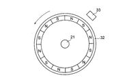
- the motor generator 3 is mechanically connected to the internal combustion engine 2 as shown in FIG.
- the motor generator 3 is based on an AC generator (ACG), and is always connected to the crankshaft of the internal combustion engine 2 without a clutch.
- ACG AC generator
- the motor generator 3 is connected to stator coils 31 u, 31 v, 31 w attached to a crankcase (not shown) of the internal combustion engine 2, and the end of the crankshaft 21 of the internal combustion engine 2.
- An attached flywheel (magnet rotor) 32 and a position detector 33 provided on the flywheel 32 are included.
- the stator coils 31u, 31v, 31w are not shown. Further, the position of the position detector 33 is not limited to that shown in FIG.
- N-pole magnets and S-pole magnets are alternately attached to the inside of the flywheel 32.
- a total of 12 magnets are attached at 30 ° intervals.
- the number of magnets is not limited to twelve.
- the position detection unit 33 transmits a pulse signal to the control device 1 every time the flywheel 32 rotates 30 °.
- This position detector 33 is, for example, a Hall element.
- the Hall element is preferably provided for each of the U phase, the V phase, and the W phase. The pulse signal detected by the Hall element is transmitted to the control device 1.
- Control device 1 calculates the rotational speed of motor generator 3 (flywheel 32) based on the pulse signal received from position detector 33.
- a relatively large number of magnets can be provided on the flywheel 32 having a diameter larger than that of the crankshaft 21. Therefore, the control device 1 can calculate the rotation speed with higher resolution than the conventional engine rotation speed by using the signal of the position detection unit 33. Since the flywheel 32 is always connected to the crankshaft 21, the rotational speed of the flywheel 32 (motor generator 3) is always the same as the rotational speed of the crankshaft 21 (internal combustion engine 2). Therefore, the rotation speed of the motor generator 3 calculated using the position detection unit 33 can be used as the rotation speed of the internal combustion engine 2.
- the motor generator 3 is configured to generate electric power upon receiving the rotation of the internal combustion engine 2 and to apply torque to the internal combustion engine 2. More specifically, the motor generator 3 generates power when it is rotationally driven by the internal combustion engine 2 and outputs three-phase AC power to the power conversion circuit 5. Then, the power conversion circuit 5 converts the three-phase AC power into DC power and charges the battery B (DC power supply) of the battery device 6. On the other hand, when applying torque to the internal combustion engine 2, the motor generator 3 is rotated by the three-phase AC power output from the power conversion circuit 5 to assist the internal combustion engine 2.
- the motor generator 3 may function as a starter motor (cell motor) that starts rotating the internal combustion engine 2 when the hybrid vehicle 30 starts.
- the ignition device 4 receives a control signal from the control device 1 and ignites the air-fuel mixture compressed in the cylinder of the internal combustion engine 2 at an appropriate timing.
- the type of the ignition device 4 is not particularly limited, and may be a CDI (Capacitive Discharge Ignition) type or a full transistor type.
- the power conversion circuit 5 converts the DC power output from the battery B of the battery device 6 into three-phase AC power and supplies it to the motor generator 3.
- the generator 3 is driven.
- the power conversion circuit 5 converts the three-phase AC power supplied from the motor generator 3 into DC power and outputs it to the battery B of the battery device 6.
- the power conversion circuit 5 is composed of a three-phase full bridge circuit.
- Semiconductor switches Q1, Q3, and Q5 are high-side switches, and semiconductor switches Q2, Q4, and Q6 are low-side switches.
- the control terminals of the semiconductor switches Q1 to Q6 are electrically connected to the control device 1.
- the semiconductor switches Q1 to Q6 are, for example, MOSFETs or IGBTs.
- a smoothing capacitor C is provided between the power supply terminal 5a and the power supply terminal 5b.
- the semiconductor switch Q1 is connected between the power supply terminal 5a to which the positive electrode of the battery B is connected and the terminal 3a of the motor generator 3.
- the semiconductor switch Q3 is connected between the power supply terminal 5a to which the positive electrode of the battery B is connected and the terminal 3b of the motor generator 3.
- Semiconductor switch Q5 is connected between power supply terminal 5a to which the positive electrode of battery B is connected and terminal 3c of motor generator 3.
- the semiconductor switch Q2 is connected between the power supply terminal 5b to which the negative electrode of the battery B is connected and the terminal 3a of the motor generator 3.
- the semiconductor switch Q4 is connected between the power supply terminal 5b to which the negative electrode of the battery B is connected and the terminal 3b of the motor generator 3.
- the semiconductor switch Q6 is connected between the power supply terminal 5b to which the negative electrode of the battery B is connected and the terminal 3c of the motor generator 3.
- the terminal 3a is a U-phase terminal
- the terminal 3b is a V-phase terminal
- the terminal 3c is a W-phase terminal.
- the battery device 6 includes a chargeable / dischargeable battery B and a battery management unit (BMU) (not shown) for managing the battery B.
- the battery B can store electric power generated by the motor generator 3 and can supply electric power to the motor generator 3.
- the kind of battery B is not specifically limited, For example, it is a lithium ion battery.
- the battery management unit transmits information regarding the voltage of the battery B and the state of the battery B (battery information) to the control device 1.
- the storage device 7 stores information used by the control device 1 (various maps, operation programs, etc. for controlling the internal combustion engine 2 and the motor generator 3).
- the storage device 7 is composed of, for example, a nonvolatile semiconductor memory.
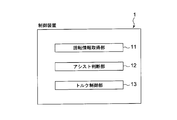
- control device 1 Next, the details of the control device 1 will be described with reference to FIG.
- the control device 1 includes a rotation information acquisition unit 11, an assist determination unit 12, and a torque control unit 13.
- the rotation information acquisition unit 11 acquires rotation information of the motor generator 3 having higher resolution than the rotation information of the internal combustion engine 2.
- rotation information is a rotation speed or a rotation speed.
- the rotation information acquisition unit 11 acquires the rotation speed of the motor generator 3 calculated based on the pulse signal received from the position detection unit 33.
- the rotation information acquisition unit 11 itself may calculate the rotation speed of the motor generator 3 based on the pulse signal from the position detection unit 33. Since the flywheel 32 is mechanically connected to the crankshaft 21 as described above, the rotational speed of the motor generator 3 (flywheel 32) acquired by the rotation information acquisition unit 11 is that of the internal combustion engine 2 (crankshaft 21). Equal to rotation speed.
- the assist determination unit 12 determines the start assist by the motor generator 3 based on the rotation information of the motor generator 3 acquired by the rotation information acquisition unit 11. An example of the determination flow will be described later with reference to FIG. Since the determination regarding the start assist is made based on the rotation speed of the motor generator 3 having a higher resolution than the rotation speed (engine speed) of the internal combustion engine 2, the assist determination unit 12 can quickly make a determination regarding the start assist.
- the assist determination unit 12 determines whether the start of the internal combustion engine 2 has been completed and whether the rotation speed of the motor generator 3 is equal to or less than the assist permission rotation speed. To do. When the start of the internal combustion engine 2 is completed (condition 1) and the rotation speed of the motor generator 3 is equal to or lower than the assist permission rotation speed (condition 2), the assist determination unit 12 permits the start assist. Further, in addition to the conditions 1 and 2, the assist determination unit 12 may permit the start assist when the throttle opening corresponding to the driver's accelerator operation is equal to or greater than the assist permission lower limit value.
- the assist determination unit 12 cancels the start assist permission when the motor generator 3 is in an abnormal state or when the brake control is being performed. Thereby, it is possible to prevent the start assist from being performed under a situation such as failure of the motor generator 3 or brake operation.
- brake control means that the motor generator 3 (for example, a motor generator based on the AC generator ACG) generates a negative motor torque to be braked, or the motor generator 3 is put into a short state to perform braking. It means to apply.
- the “short state” is a state in which one of the high-side switch (semiconductor switches Q1, Q3, Q5) and the low-side switch (semiconductor switches Q2, Q4, Q6) is turned on and the other is turned off.
- the assist determination unit 12 has started the internal combustion engine 2, the rotation speed of the motor generator 3 is equal to or lower than the assist permission rotation speed, and the throttle opening corresponding to the driver's accelerator operation is the assist permission lower limit. If it is less than the value, start assistance is accepted. When the start assist is accepted, the start assist is permitted as soon as the throttle opening exceeds the assist permission lower limit.
- the torque control unit 13 controls the torque (motor torque) that the motor generator 3 applies to the internal combustion engine 2. More specifically, the torque control unit 13 calculates the energization timing and duty ratio of the PWM signal output to the power conversion circuit 5 based on the required motor torque, and outputs the PWM signal to the semiconductor switches Q1 to Q6. .
- the energization timing is the advance (advance angle) or delay (retard angle) of the phase of the PWM signal with respect to the motor electrical angle.
- the energization timing is an advance angle when the motor generator 3 performs an assist operation. Is retarded.
- the torque control unit 13 gradually increases the motor torque when the start assist is permitted. In other words, when the start assist is permitted, the torque control unit 13 increases the torque applied by the motor generator 3 to the internal combustion engine 2 at a prescribed time change rate or less. Thereby, start assistance can be performed without giving a driver a sense of incongruity.
- the torque control unit 13 may increase the torque applied by the motor generator 3 to the internal combustion engine 2 in a stepped manner as shown in FIG.
- the torque control unit 13 may change the increase amount of the motor torque based on the rotation information of the motor generator 3. For example, as the rotational speed of the motor generator 3 is higher, the motor torque may be increased as shown in FIG. Thereby, smooth start assistance can be performed.
- the control device 1 acquires the rotation information of the motor generator 3 (flywheel 32) having higher resolution than the rotation information of the internal combustion engine 2 (crankshaft 21), and uses this rotation information as the rotation information. Based on this, a decision regarding start assistance is made.
- the rotation information With high resolution, the rotation speed of the internal combustion engine 2 can be quickly determined and a determination regarding the start assist can be made. Therefore, according to the present embodiment, it is possible to quickly make a determination regarding the start assist of the hybrid vehicle 30.
- the rotation information acquisition unit 11 acquires rotation information of the motor generator 3 (flywheel 32) having higher resolution than the rotation information of the internal combustion engine 2 (crankshaft 21) (step S1).
- the assist determination unit 12 After obtaining the rotation information of the motor generator 3, the assist determination unit 12 makes a determination on the start assist by the motor generator 3 based on the rotation information (step S2). In the present embodiment, the determination regarding the start assist is performed as follows along the flowchart of FIG.
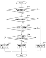
- the assist determination unit 12 determines whether or not there is an instruction to drive the motor generator 3 (step S21). When there is no drive instruction (S21; Yes), the process proceeds to step S22. On the other hand, when there is a drive instruction (S21; No), the assist determination unit 12 gives priority to the drive instruction and does not allow start assistance (step S27). ).
- the assist determination unit 12 determines whether or not the internal combustion engine 2 has been started (step S22). Specifically, when the rotation speed indicated by the rotation information acquired in step S1 is equal to or higher than a specified threshold (internal combustion engine start completion rotation speed), it is determined that the internal combustion engine 2 has been started. When the start is completed (S22; Yes), the process proceeds to step S23. On the other hand, when the start is not completed (S22; No), the assist determination unit 12 does not permit the start assist (step S27).
- the assist determination unit 12 determines whether or not the rotational speed of the motor generator 3 (internal combustion engine 2) is equal to or lower than an assist permission lower limit value (step). S23). When the rotation speed of the motor generator 3 is equal to or lower than the assist permission lower limit value (S23; Yes), the process proceeds to step S24. On the other hand, when the rotation speed of the motor generator 3 is larger than the assist permission lower limit value (S23; No), The determination unit 12 does not allow start assistance (step S27).
- the assist determination unit 12 determines that the throttle opening corresponding to the driver's accelerator operation is greater than or equal to the assist permission lower limit. It is determined whether or not there is (step S24). If the throttle opening is equal to or greater than the assist permission lower limit (S24; Yes), the assist determination unit 12 permits the start assist (step S25). When the start assist is permitted, the start assist is executed unless there is a prohibition factor such as abnormality of the motor generator 3 or brake control. On the other hand, when the throttle opening is less than the assist permission lower limit (S24; No), the assist determination unit 12 accepts start assist (step S26). When start assist is accepted, start assist is executed when the throttle opening is equal to or greater than the assist permission lower limit unless there is a prohibition factor.
- the rotation information of the motor generator 3 having higher resolution than the rotation information (engine rotation speed) of the internal combustion engine 2 is acquired, and the acquired rotation speed of the motor generator 3 is stepped. Used in the determination of S22 and step S23. Thereby, the judgment regarding the start assistance of the hybrid vehicle 30 can be quickly performed. As a result, the time lag of the start assist is shortened, and an effect such as reducing the uncomfortable feeling given to the driver of the hybrid vehicle 30 is obtained.
Landscapes
- Engineering & Computer Science (AREA)
- Transportation (AREA)
- Mechanical Engineering (AREA)
- Chemical & Material Sciences (AREA)
- Combustion & Propulsion (AREA)
- Automation & Control Theory (AREA)
- Power Engineering (AREA)
- Electric Propulsion And Braking For Vehicles (AREA)
- Hybrid Electric Vehicles (AREA)
Abstract
【課題】ハイブリッド車両の発進アシストに関する判断を迅速に行う。 【解決手段】実施形態による制御装置1は、内燃機関2に機械的に接続され、内燃機関2の回転を受けて発電可能であるとともに内燃機関2にトルクを付与可能なモータジェネレータ3を有するハイブリッド車両30の制御装置であって、内燃機関2の回転情報よりも分解能が高いモータジェネレータ3の回転情報を取得する回転情報取得部11と、 モータジェネレータ3の回転情報に基づいて、モータジェネレータ3による発進アシストに関する判断を行うアシスト判断部12と、を備える。
Description
本発明は、ハイブリッド車両の制御装置および制御方法に関する。
従来、内燃機関(エンジン)と電動機(モータ)を動力源とするハイブリッド車両が知られている。このハイブリッド車両では、電動機がモータジェネレータとして構成されているものがある。モータジェネレータは、内燃機関にトルクを付与して内燃機関をアシストすることが可能であるとともに、内燃機関による走行中に発電を行うことも可能である。
また、従来、二輪車等の車両では、内燃機関のクランク軸に接続され、当該内燃機関の回転を受けて発電する交流発電機(Alternating Current Generator:ACG)が設けられている。交流発電機で発電された交流電力は、レギュレートレクチファイヤ(REG/RECT)によってバッテリに応じた直流電力に変換された後、バッテリに供給される。
特許文献1には、電動機による回生(充電)を確保しつつ、発進または走行の駆動力特性を向上させることを目的としたハイブリッド車両の制御装置が記載されている。
ところで、ハイブリッド車両において、上記の交流発電機を、発電機として機能するだけでなく、内燃機関にトルクを付与可能な電動機としても機能することが可能なモータジェネレータとして構成し、このモータジェネレータにより内燃機関の発進アシストを行うことが考えられる。「発進アシスト」は、アイドル状態(アイドリング状態)の内燃機関を再始動させるために内燃機関にトルクを付与することである。
従来の内燃機関の制御では、クランク軸が180°回転する毎に算出される回転速度を用いている。クランク軸の周面にはN極およびS極の磁石が1つずつ設けられており、この回転速度は、クランク軸の近くに配置されたホール素子が検出するパルス信号に基づいて算出される。本願では、このようにして算出される回転速度を「エンジン回転速度」という。
ハイブリッド車両においても、発進アシストする際に、内燃機関の回転速度を把握するためにエンジン回転速度が用いられる。しかしながら、エンジン回転速度は分解能が低いため、内燃機関の回転速度を確定するのに時間を要し、タイムラグが生じるという課題があった。すなわち、従来は、発進アシストに関する判断を迅速に行うことが困難であるという課題があった。
そこで、本発明は、ハイブリッド車両の発進アシストに関する判断を迅速に行うことが可能なハイブリッド車両の制御装置および制御方法を提供することを目的とする。
本発明に係る制御装置は、
内燃機関に機械的に接続され、前記内燃機関の回転を受けて発電可能であるとともに前記内燃機関にトルクを付与可能なモータジェネレータを有するハイブリッド車両の制御装置であって、
前記内燃機関の回転情報よりも分解能が高い前記モータジェネレータの回転情報を取得する回転情報取得部と、
前記モータジェネレータの回転情報に基づいて、前記モータジェネレータによる発進アシストに関する判断を行うアシスト判断部と、
を備えることを特徴とする。
内燃機関に機械的に接続され、前記内燃機関の回転を受けて発電可能であるとともに前記内燃機関にトルクを付与可能なモータジェネレータを有するハイブリッド車両の制御装置であって、
前記内燃機関の回転情報よりも分解能が高い前記モータジェネレータの回転情報を取得する回転情報取得部と、
前記モータジェネレータの回転情報に基づいて、前記モータジェネレータによる発進アシストに関する判断を行うアシスト判断部と、
を備えることを特徴とする。
また、前記制御装置において、
前記アシスト判断部は、
前記モータジェネレータの回転情報に基づいて、前記内燃機関の始動が完了しているか否か、および、前記モータジェネレータの回転速度がアシスト許可回転速度以下であるか否かを判定し、
前記内燃機関の始動が完了しており、かつ前記モータジェネレータの回転速度がアシスト許可回転速度以下である場合に、前記発進アシストを許可するようにしてもよい。
前記アシスト判断部は、
前記モータジェネレータの回転情報に基づいて、前記内燃機関の始動が完了しているか否か、および、前記モータジェネレータの回転速度がアシスト許可回転速度以下であるか否かを判定し、
前記内燃機関の始動が完了しており、かつ前記モータジェネレータの回転速度がアシスト許可回転速度以下である場合に、前記発進アシストを許可するようにしてもよい。
また、前記制御装置において、
前記アシスト判断部は、運転者のアクセル操作に対応したスロットル開度がアシスト許可下限値以上の場合に、前記発進アシストを許可するようにしてもよい。
前記アシスト判断部は、運転者のアクセル操作に対応したスロットル開度がアシスト許可下限値以上の場合に、前記発進アシストを許可するようにしてもよい。
また、前記制御装置において、
前記アシスト判断部は、前記モータジェネレータが異常状態である場合、またはブレーキ制御がなされている場合、前記発進アシストの許可を取り消すようにしてもよい。
前記アシスト判断部は、前記モータジェネレータが異常状態である場合、またはブレーキ制御がなされている場合、前記発進アシストの許可を取り消すようにしてもよい。
また、前記制御装置において、
前記アシスト判断部は、
前記モータジェネレータの回転情報に基づいて、前記内燃機関の始動が完了しているか否か、および、前記モータジェネレータの回転速度がアシスト許可回転速度以下であるか否かを判定し、
前記内燃機関の始動が完了しており、前記モータジェネレータの回転速度がアシスト許可回転速度以下であり、かつ運転者のアクセル操作に対応したスロットル開度がアシスト許可下限値未満の場合に、前記発進アシストを受け付けるようにしてもよい。
前記アシスト判断部は、
前記モータジェネレータの回転情報に基づいて、前記内燃機関の始動が完了しているか否か、および、前記モータジェネレータの回転速度がアシスト許可回転速度以下であるか否かを判定し、
前記内燃機関の始動が完了しており、前記モータジェネレータの回転速度がアシスト許可回転速度以下であり、かつ運転者のアクセル操作に対応したスロットル開度がアシスト許可下限値未満の場合に、前記発進アシストを受け付けるようにしてもよい。
また、前記制御装置において、
前記発進アシストが許可された場合、前記モータジェネレータが前記内燃機関に付与するトルクを規定の時間変化率以下で増加させるトルク制御部をさらに備えてもよい。
前記発進アシストが許可された場合、前記モータジェネレータが前記内燃機関に付与するトルクを規定の時間変化率以下で増加させるトルク制御部をさらに備えてもよい。
また、前記制御装置において、
前記トルク制御部は、前記モータジェネレータが前記内燃機関に付与するトルクをステップ状に増加させてもよい。
前記トルク制御部は、前記モータジェネレータが前記内燃機関に付与するトルクをステップ状に増加させてもよい。
また、前記制御装置において、
前記トルク制御部は、前記モータジェネレータの回転情報に基づいて前記トルクの上げ幅を変化させてもよい。
前記トルク制御部は、前記モータジェネレータの回転情報に基づいて前記トルクの上げ幅を変化させてもよい。
また、前記制御装置において、
前記モータジェネレータは、前記ハイブリッド車両が発車する際に前記内燃機関を回転始動させるものであってもよい。
前記モータジェネレータは、前記ハイブリッド車両が発車する際に前記内燃機関を回転始動させるものであってもよい。
また、前記制御装置において、
前記ハイブリッド車両は、ハイブリッド二輪車であってもよい。
前記ハイブリッド車両は、ハイブリッド二輪車であってもよい。
本発明に係るハイブリッド車両の制御方法は、
内燃機関に機械的に接続され、前記内燃機関の回転を受けて発電可能であるとともに前記内燃機関にトルクを付与可能なモータジェネレータを有するハイブリッド車両の制御方法であって、
回転情報取得部が、前記内燃機関の回転情報よりも分解能が高い前記モータジェネレータの回転情報を取得し、
アシスト判断部が、前記モータジェネレータの回転情報に基づいて、前記モータジェネレータによる発進アシストに関する判断を行うことを特徴とする。
内燃機関に機械的に接続され、前記内燃機関の回転を受けて発電可能であるとともに前記内燃機関にトルクを付与可能なモータジェネレータを有するハイブリッド車両の制御方法であって、
回転情報取得部が、前記内燃機関の回転情報よりも分解能が高い前記モータジェネレータの回転情報を取得し、
アシスト判断部が、前記モータジェネレータの回転情報に基づいて、前記モータジェネレータによる発進アシストに関する判断を行うことを特徴とする。
本発明では、内燃機関の回転情報よりも分解能が高いモータジェネレータの回転情報を取得し、このモータジェネレータの回転情報に基づいて発進アシストに関する判断を行う。これにより、本発明によれば、ハイブリッド車両の発進アシストに関する判断を迅速に行うことができる。
以下、図面を参照しつつ本発明の実施形態について説明する。
まず、図1~図3を参照して、実施形態に係るハイブリッド車両30の概略的な構成について説明する。
ハイブリッド車両30は、内燃機関と電動機の2つの動力源を有するハイブリッド型の二輪車(ハイブリッド二輪車)である。なお、ハイブリッド車両30は、二輪車に限らず、ハイブリッド型の他の車両(四輪車等)であってもよい。
ハイブリッド車両30は、図1に示すように、制御装置1と、内燃機関(エンジン)2と、モータジェネレータ(Motor Generator:MG)3と、点火装置4と、電力変換回路5と、バッテリ装置6と、記憶装置7と、クラッチ8と、車輪9とを備えている。図1の車輪9は、ハイブリッド二輪車の後輪を示している。
制御装置1は、モータジェネレータ3による発進アシストに関する判断を行うように構成されている。また、制御装置1は、モータジェネレータ3が内燃機関2に付与するトルク(以下、単に「モータトルク」ともいう。)を制御する。制御装置1の詳細については後述する。なお、制御装置1は、ハイブリッド車両30全体を統御するECU(Electronic Control Unit)として構成されてもよい。
内燃機関2は、燃料ガス(混合気)が燃焼したときの圧力を利用して、クラッチ8を介して車輪9に回転駆動力を出力する。内燃機関2のクランク軸21は、ピストン(図示せず)の上下運動を回転運動に変える。
なお、内燃機関2の種類は特に限定されず、例えば4ストロークエンジンでも、2ストロークエンジンでもよい。また、内燃機関2の吸気経路には、電子式スロットルバルブ(図示せず)が配設されていてもよい。この場合、運転者(ライダー)のアクセル(グリップ)操作により設定されたスロットル開度をアクセルポジションセンサが読み取り、電気信号として制御装置1に送信する。その後、制御装置1は、受信した設定スロットル開度に基づいてスロットル開度を計算し、スロットル開度の調整手段(スロットルモータ等)に指令を送信する。
モータジェネレータ3は、図1に示すように、内燃機関2に機械的に接続されている。本実施形態では、モータジェネレータ3は、交流発電機(ACG)をベースとしたものであり、内燃機関2のクランク軸にクラッチを介さずに常時接続されている。
図2および図3に示すように、モータジェネレータ3は、内燃機関2のクランクケース(図示せず)に取り付けられたステータコイル31u,31v,31wと、内燃機関2のクランク軸21の端部に取り付けられたフライホイール(マグネットロータ)32と、フライホイール32に設けられた位置検出部33とを有する。なお、図2では、ステータコイル31u,31v,31wは図示していない。また、位置検出部33の配置位置は図2に示すものに限られない。
図2に示すように、フライホイール32の内側には、N極の磁石とS極の磁石が交互に取り付けられている。本実施形態では、磁石は30°間隔で計12個取り付けられている。なお、磁石の個数は12個に限られるものではない。位置検出部33は、フライホイール32が30°回転する毎にパルス信号を制御装置1に送信する。この位置検出部33は、例えばホール素子である。ホール素子は、好ましくは、U相、V相およびW相の各相に対して設けられる。ホール素子が検出したパルス信号は制御装置1に送信される。
制御装置1は、位置検出部33から受信したパルス信号に基づいてモータジェネレータ3(フライホイール32)の回転速度を算出する。クランク軸21よりも径の大きいフライホイール32には、比較的多数の磁石を設けることが可能である。よって、制御装置1は、位置検出部33の信号を利用することにより、従来のエンジン回転速度よりも高分解能で回転速度を算出することができる。フライホイール32がクランク軸21に常時接続されているため、フライホイール32(モータジェネレータ3)の回転速度はクランク軸21(内燃機関2)の回転速度と常に同じである。したがって、位置検出部33を用いて算出されたモータジェネレータ3の回転速度を内燃機関2の回転速度として使用することが可能である。
モータジェネレータ3のフライホイール32が内燃機関2のクランク軸21と同期して回転することにより、ステータコイル31u,31v,31wから三相の交流電力が出力される。反対に、ステータコイル31u,31v,31wに三相交流電流を通電することにより、フライホイール32を介して内燃機関2にトルクが付与される。
上記のようにモータジェネレータ3は、内燃機関2の回転を受けて発電可能であるとともに、内燃機関2にトルクを付与可能に構成されている。より詳しくは、モータジェネレータ3は、内燃機関2により回転駆動されているときは発電を行って、三相交流電力を電力変換回路5に出力する。そして、電力変換回路5は、三相交流電力を直流電力に変換し、バッテリ装置6の有するバッテリB(直流電源)を充電する。一方、内燃機関2にトルクを付与するときは、モータジェネレータ3は、電力変換回路5から出力される三相交流電力により回転して、内燃機関2をアシストする。
なお、モータジェネレータ3は、ハイブリッド車両30が発車する際に内燃機関2を回転始動させる始動モータ(セルモータ)として機能してもよい。
点火装置4は、制御装置1から制御信号を受信し、内燃機関2のシリンダー内で圧縮された混合気に適切なタイミングで着火する。なお、点火装置4の種別は特に限定されず、CDI(Capacitive Discharge Ignition)式でもよいし、フルトランジスタ式でもよい。
電力変換回路5は、モータジェネレータ3が内燃機関2をアシストする際には、バッテリ装置6のバッテリBから出力される直流電力を三相の交流電力に変換してモータジェネレータ3に供給し、モータジェネレータ3を駆動する。一方、モータジェネレータ3が発電する際には、電力変換回路5は、モータジェネレータ3から供給される三相交流電力を直流電力に変換してバッテリ装置6のバッテリBに出力する。
図3に示すように、電力変換回路5は三相フルブリッジ回路から構成される。半導体スイッチQ1,Q3,Q5はハイサイドスイッチであり、半導体スイッチQ2,Q4,Q6はローサイドスイッチである。半導体スイッチQ1~Q6の制御端子は、制御装置1に電気的に接続されている。なお、半導体スイッチQ1~Q6は、例えばMOSFETまたはIGBT等である。電源端子5aと電源端子5bとの間には平滑コンデンサCが設けられている。
半導体スイッチQ1は、バッテリBの正極が接続された電源端子5aと、モータジェネレータ3の端子3aとの間に接続されている。同様に、半導体スイッチQ3は、バッテリBの正極が接続された電源端子5aと、モータジェネレータ3の端子3bとの間に接続されている。半導体スイッチQ5は、バッテリBの正極が接続された電源端子5aと、モータジェネレータ3の端子3cとの間に接続されている。
半導体スイッチQ2は、バッテリBの負極が接続された電源端子5bと、モータジェネレータ3の端子3aとの間に接続されている。同様に、半導体スイッチQ4は、バッテリBの負極が接続された電源端子5bと、モータジェネレータ3の端子3bとの間に接続されている。半導体スイッチQ6は、バッテリBの負極が接続された電源端子5bと、モータジェネレータ3の端子3cとの間に接続されている。なお、端子3aはU相の端子であり、端子3bはV相の端子であり、端子3cはW相の端子である。
バッテリ装置6は、充放電可能なバッテリBと、このバッテリBを管理するバッテリ管理ユニット(Battery Management Unit:BMU)(図示せず)とを含む。バッテリBは、モータジェネレータ3により発電された電力を蓄電可能であるとともに、モータジェネレータ3に電力を供給可能である。バッテリBの種類は特に限定されず、例えばリチウムイオン電池である。バッテリ管理ユニットは、バッテリBの電圧やバッテリBの状態に関する情報(バッテリ情報)を制御装置1に送信する。
記憶装置7は、制御装置1により用いられる情報(内燃機関2やモータジェネレータ3を制御するための各種マップ、動作プログラム等)を記憶する。この記憶装置7は、例えば不揮発性の半導体メモリから構成される。
次に、図4を参照して、制御装置1の詳細について説明する。
制御装置1は、図4に示すように、回転情報取得部11と、アシスト判断部12と、トルク制御部13とを有している。
回転情報取得部11は、内燃機関2の回転情報よりも分解能が高いモータジェネレータ3の回転情報を取得する。ここで、「回転情報」は、回転速度または回転数である。本実施形態では、回転情報取得部11は、位置検出部33から受信したパルス信号に基づいて算出されたモータジェネレータ3の回転速度を取得する。なお、回転情報取得部11自身が、位置検出部33のパルス信号に基づいてモータジェネレータ3の回転速度を算出してもよい。前述のようにフライホイール32がクランク軸21に機械的に接続されているため、回転情報取得部11が取得するモータジェネレータ3(フライホイール32)の回転速度は内燃機関2(クランク軸21)の回転速度に等しい。
アシスト判断部12は、回転情報取得部11により取得されたモータジェネレータ3の回転情報に基づいて、モータジェネレータ3による発進アシストに関する判断を行う。判断フローの例については図7を用いて後述する。内燃機関2の回転速度(エンジン回転速度)よりも分解能が高いモータジェネレータ3の回転速度に基づいて発進アシストに関する判断を行うため、アシスト判断部12は発進アシストに関する判断を迅速に行うことができる。
次に、発進アシストに関する判断の詳細について説明する。
アシスト判断部12は、モータジェネレータ3の回転情報に基づいて、内燃機関2の始動が完了しているか否か、および、モータジェネレータ3の回転速度がアシスト許可回転速度以下であるか否かを判定する。そして、内燃機関2の始動が完了しており(条件1)、かつモータジェネレータ3の回転速度がアシスト許可回転速度以下である(条件2)場合に、アシスト判断部12は発進アシストを許可する。さらに、アシスト判断部12は、条件1および条件2に加えて、運転者のアクセル操作に対応したスロットル開度がアシスト許可下限値以上である場合に、発進アシストを許可するようにしてもよい。
なお、アシスト判断部12は、モータジェネレータ3が異常状態である場合、またはブレーキ制御がなされている場合は、発進アシストの許可を取り消す。これにより、モータジェネレータ3の故障やブレーキ操作などの状況下で発進アシストが行われることを防止できる。ここでいう「ブレーキ制御」は、モータジェネレータ3(例えば交流発電機ACGをベースにしたモータジェネレータ)に負のモータトルクを発生させてブレーキをかけること、あるいは、モータジェネレータ3をショート状態にしてブレーキをかけることをいう。「ショート状態」とは、ハイサイドスイッチ(半導体スイッチQ1,Q3,Q5)およびローサイドスイッチ(半導体スイッチQ2,Q4,Q6)のうち一方をオンにし、他方をオフにした状態のことである。
また、アシスト判断部12は、内燃機関2の始動が完了しており、モータジェネレータ3の回転速度がアシスト許可回転速度以下であり、かつ運転者のアクセル操作に対応したスロットル開度がアシスト許可下限値未満の場合に、発進アシストを受け付ける。発進アシストが受け付けられた場合、スロットル開度がアシスト許可下限値以上になると、ただちに発進アシストが許可される。
トルク制御部13は、モータジェネレータ3が内燃機関2に付与するトルク(モータトルク)を制御する。より具体的には、トルク制御部13は、所要のモータトルクに基づいて、電力変換回路5に出力するPWM信号の通電タイミングおよびデューティ比を算出し、半導体スイッチQ1~Q6にPWM信号を出力する。なお、通電タイミングは、モータ電気角に対するPWM信号の位相の進み(進角)または遅れ(遅角)のことであり、モータジェネレータ3がアシスト動作する際には進角となり、発電動作する際には遅角となる。
トルク制御部13は、発進アシストが許可された場合に、モータトルクを徐々に増加させる。換言すれば、発進アシストが許可された場合、トルク制御部13は、モータジェネレータ3が内燃機関2に付与するトルクを規定の時間変化率以下で増加させる。これにより、運転者に違和感を与えずに発進アシストを行うことができる。
なお、トルク制御部13は、図5に示すように、モータジェネレータ3が内燃機関2に付与するトルクをステップ状に増加させてもよい。この場合、トルク制御部13は、モータジェネレータ3の回転情報に基づいてモータトルクの上げ幅を変化させてもよい。例えば、モータジェネレータ3の回転速度が高いほど、図5に示すようにモータトルクの上げ幅を大きくしてもよい。これにより、スムーズな発進アシストを行うことができる。
上記のように、本実施形態に係る制御装置1では、内燃機関2(クランク軸21)の回転情報よりも分解能が高いモータジェネレータ3(フライホイール32)の回転情報を取得し、この回転情報に基づいて発進アシストに関する判断を行う。分解能が高い回転情報を使用することで、内燃機関2の回転速度を速やかに確定させ、発進アシストに関する判断を行うことができる。よって、本実施形態によれば、ハイブリッド車両30の発進アシストに関する判断を迅速に行うことができる。
次に、図6および図7のフローチャートを参照して、本実施形態に係るハイブリッド車両30の制御方法について説明する。
まず、回転情報取得部11が、内燃機関2(クランク軸21)の回転情報よりも分解能が高いモータジェネレータ3(フライホイール32)の回転情報を取得する(ステップS1)。
モータジェネレータ3の回転情報を取得した後、アシスト判断部12が、この回転情報に基づいて、モータジェネレータ3による発進アシストに関する判断を行う(ステップS2)。本実施形態では、発進アシストに関する判断は、図7のフローチャートに沿って以下のように行われる。
まず、アシスト判断部12は、モータジェネレータ3の駆動指示がないか否かを判定する(ステップS21)。駆動指示がない場合(S21;Yes)、ステップS22に進み、一方、駆動指示がある場合(S21;No)、アシスト判断部12は、当該駆動指示を優先し、発進アシストを許可しない(ステップS27)。
モータジェネレータ3の駆動指示がない場合(S21;Yes)、アシスト判断部12は、内燃機関2の始動が完了しているか否かを判定する(ステップS22)。具体的には、ステップS1で取得した回転情報の示す回転速度が、規定の閾値(内燃機関始動完了回転速度)以上である場合に、内燃機関2の始動が完了していると判定する。始動が完了している場合(S22;Yes)、ステップS23に進み、一方、始動が完了していない場合(S22;No)、アシスト判断部12は、発進アシストを許可しない(ステップS27)。
内燃機関2の始動が完了している場合(S22;Yes)、アシスト判断部12は、モータジェネレータ3(内燃機関2)の回転速度がアシスト許可下限値以下であるか否かを判定する(ステップS23)。モータジェネレータ3の回転速度がアシスト許可下限値以下である場合(S23;Yes)、ステップS24に進み、一方、モータジェネレータ3の回転速度がアシスト許可下限値よりも大きい場合(S23;No)、アシスト判断部12は、発進アシストを許可しない(ステップS27)。
モータジェネレータ3(内燃機関2)の回転速度がアシスト許可下限値以下である場合(S23;Yes)、アシスト判断部12は、運転者のアクセル操作に対応したスロットル開度がアシスト許可下限値以上であるか否かを判定する(ステップS24)。スロットル開度がアシスト許可下限値以上である場合(S24;Yes)、アシスト判断部12は発進アシストを許可する(ステップS25)。発進アシストが許可されると、モータジェネレータ3の異常やブレーキ制御などの禁止要因がない限り、発進アシストが実行される。一方、スロットル開度がアシスト許可下限値未満である場合(S24;No)、アシスト判断部12は、発進アシストを受け付ける(ステップS26)。発進アシストが受け付けられると、スロットル開度がアシスト許可下限値以上になった場合に、禁止要因がない限り、発進アシストが実行される。
上記のように、本実施形態に係る制御方法では、内燃機関2の回転情報(エンジン回転速度)よりも分解能が高いモータジェネレータ3の回転情報を取得し、取得したモータジェネレータ3の回転速度をステップS22およびステップS23の判定で用いる。これにより、ハイブリッド車両30の発進アシストに関する判断を迅速に行うことができる。その結果、発進アシストのタイムラグが短くなり、ハイブリッド車両30の運転者に与える違和感を軽減する等の効果が得られる。
上記の記載に基づいて、当業者であれば、本発明の追加の効果や種々の変形を想到できるかもしれないが、本発明の態様は、上述した個々の実施形態に限定されるものではない。異なる実施形態にわたる構成要素を適宜組み合わせてもよい。特許請求の範囲に規定された内容及びその均等物から導き出される本発明の概念的な思想と趣旨を逸脱しない範囲で種々の追加、変更及び部分的削除が可能である。
1 制御装置
2 内燃機関(エンジン)
21 クランク軸
3 モータジェネレータ
3a,3b,3c 端子
4 点火装置
5 電力変換回路
5a,5b 電源端子
6 バッテリ装置
7 記憶装置
8 クラッチ
9 車輪
11 回転情報取得部
12 アシスト判断部
13 トルク制御部
30 ハイブリッド車両
31u,31v,31w ステータコイル
32 フライホイール
33 位置検出部
B バッテリ
C 平滑コンデンサ
Q1~Q6 半導体スイッチ
2 内燃機関(エンジン)
21 クランク軸
3 モータジェネレータ
3a,3b,3c 端子
4 点火装置
5 電力変換回路
5a,5b 電源端子
6 バッテリ装置
7 記憶装置
8 クラッチ
9 車輪
11 回転情報取得部
12 アシスト判断部
13 トルク制御部
30 ハイブリッド車両
31u,31v,31w ステータコイル
32 フライホイール
33 位置検出部
B バッテリ
C 平滑コンデンサ
Q1~Q6 半導体スイッチ
Claims (11)
- 内燃機関に機械的に接続され、前記内燃機関の回転を受けて発電可能であるとともに前記内燃機関にトルクを付与可能なモータジェネレータを有するハイブリッド車両の制御装置であって、
前記内燃機関の回転情報よりも分解能が高い前記モータジェネレータの回転情報を取得する回転情報取得部と、
前記モータジェネレータの回転情報に基づいて、前記モータジェネレータによる発進アシストに関する判断を行うアシスト判断部と、
を備えることを特徴とする制御装置。 - 前記アシスト判断部は、
前記モータジェネレータの回転情報に基づいて、前記内燃機関の始動が完了しているか否か、および、前記モータジェネレータの回転速度がアシスト許可回転速度以下であるか否かを判定し、
前記内燃機関の始動が完了しており、かつ前記モータジェネレータの回転速度がアシスト許可回転速度以下である場合に、前記発進アシストを許可することを特徴とする請求項1に記載の制御装置。 - 前記アシスト判断部は、運転者のアクセル操作に対応したスロットル開度がアシスト許可下限値以上の場合に、前記発進アシストを許可することを特徴とする請求項2に記載の制御装置。
- 前記アシスト判断部は、前記モータジェネレータが異常状態である場合、またはブレーキ制御がなされている場合、前記発進アシストの許可を取り消すことを特徴とする請求項3に記載の制御装置。
- 前記アシスト判断部は、
前記モータジェネレータの回転情報に基づいて、前記内燃機関の始動が完了しているか否か、および、前記モータジェネレータの回転速度がアシスト許可回転速度以下であるか否かを判定し、
前記内燃機関の始動が完了しており、前記モータジェネレータの回転速度がアシスト許可回転速度以下であり、かつ運転者のアクセル操作に対応したスロットル開度がアシスト許可下限値未満の場合に、前記発進アシストを受け付けることを特徴とする請求項1に記載の制御装置。 - 前記発進アシストが許可された場合、前記モータジェネレータが前記内燃機関に付与するトルクを規定の時間変化率以下で増加させるトルク制御部をさらに備えることを特徴とする請求項1に記載の制御装置。
- 前記トルク制御部は、前記モータジェネレータが前記内燃機関に付与するトルクをステップ状に増加させることを特徴とする請求項6に記載の制御装置。
- 前記トルク制御部は、前記モータジェネレータの回転情報に基づいて前記トルクの上げ幅を変化させることを特徴とする請求項7に記載の制御装置。
- 前記モータジェネレータは、前記ハイブリッド車両が発車する際に前記内燃機関を回転始動させるものであることを特徴とする請求項1に記載の制御装置。
- 前記ハイブリッド車両は、ハイブリッド二輪車であることを特徴とする請求項1に記載の制御装置。
- 内燃機関に機械的に接続され、前記内燃機関の回転を受けて発電可能であるとともに前記内燃機関にトルクを付与可能なモータジェネレータを有するハイブリッド車両の制御方法であって、
回転情報取得部が、前記内燃機関の回転情報よりも分解能が高い前記モータジェネレータの回転情報を取得し、
アシスト判断部が、前記モータジェネレータの回転情報に基づいて、前記モータジェネレータによる発進アシストに関する判断を行うことを特徴とする制御方法。
Priority Applications (3)
| Application Number | Priority Date | Filing Date | Title |
|---|---|---|---|
| US16/094,188 US11052748B2 (en) | 2016-07-22 | 2016-09-09 | Controlling apparatus and controlling method of hybrid vehicle |
| JP2017556996A JP6408171B2 (ja) | 2016-07-22 | 2016-09-09 | ハイブリッド車両の制御装置および制御方法 |
| EP16909560.1A EP3489103B1 (en) | 2016-07-22 | 2016-09-09 | Control apparatus and control method for hybrid vehicle |
Applications Claiming Priority (2)
| Application Number | Priority Date | Filing Date | Title |
|---|---|---|---|
| JP2016144407 | 2016-07-22 | ||
| JP2016-144407 | 2016-07-22 |
Publications (1)
| Publication Number | Publication Date |
|---|---|
| WO2018016085A1 true WO2018016085A1 (ja) | 2018-01-25 |
Family
ID=60995982
Family Applications (1)
| Application Number | Title | Priority Date | Filing Date |
|---|---|---|---|
| PCT/JP2016/076713 Ceased WO2018016085A1 (ja) | 2016-07-22 | 2016-09-09 | ハイブリッド車両の制御装置および制御方法 |
Country Status (4)
| Country | Link |
|---|---|
| US (1) | US11052748B2 (ja) |
| EP (1) | EP3489103B1 (ja) |
| JP (1) | JP6408171B2 (ja) |
| WO (1) | WO2018016085A1 (ja) |
Cited By (1)
| Publication number | Priority date | Publication date | Assignee | Title |
|---|---|---|---|---|
| WO2021053742A1 (ja) * | 2019-09-18 | 2021-03-25 | ヤマハ発動機株式会社 | リーン車両 |
Families Citing this family (3)
| Publication number | Priority date | Publication date | Assignee | Title |
|---|---|---|---|---|
| BR112019018931A2 (pt) * | 2017-03-23 | 2020-04-22 | Honda Motor Co Ltd | dispositivo de controle de motor para veículo |
| KR20220161688A (ko) * | 2021-05-31 | 2022-12-07 | 현대자동차주식회사 | 하이브리드 차량의 림폼 주행 제어 방법 |
| CN114475565B (zh) * | 2022-03-30 | 2024-03-29 | 东风汽车集团股份有限公司 | 混合动力车辆及起步控制方法、分配系统和车载控制器 |
Citations (6)
| Publication number | Priority date | Publication date | Assignee | Title |
|---|---|---|---|---|
| JP2000205002A (ja) * | 1999-01-06 | 2000-07-25 | Hitachi Ltd | ハイブリッド車駆動装置の制御装置および制御方法 |
| JP2003035361A (ja) * | 2001-04-26 | 2003-02-07 | Aisin Aw Co Ltd | ハイブリッド車両の制御装置 |
| JP2005006469A (ja) * | 2003-06-13 | 2005-01-06 | Honda Motor Co Ltd | ハイブリッド車両 |
| JP2005023886A (ja) * | 2003-07-04 | 2005-01-27 | Honda Motor Co Ltd | ハイブリッド車両の制御装置 |
| JP2013226939A (ja) | 2012-04-25 | 2013-11-07 | Honda Motor Co Ltd | ハイブリッド車両の制御装置及び制御方法 |
| JP2013249032A (ja) * | 2012-06-04 | 2013-12-12 | Nissan Motor Co Ltd | 車両の電源装置 |
Family Cites Families (9)
| Publication number | Priority date | Publication date | Assignee | Title |
|---|---|---|---|---|
| JP3942772B2 (ja) * | 1999-10-08 | 2007-07-11 | ヤマハ発動機株式会社 | シリーズハイブリッド式電動二輪車 |
| JP3775562B2 (ja) * | 2000-03-07 | 2006-05-17 | ジヤトコ株式会社 | パラレルハイブリッド車両 |
| JP2002252904A (ja) * | 2001-02-26 | 2002-09-06 | Hino Motors Ltd | ハイブリッド動力装置 |
| JP2007022244A (ja) * | 2005-07-14 | 2007-02-01 | Hino Motors Ltd | ハイブリッド自動車 |
| DE102006012384A1 (de) | 2006-03-15 | 2007-09-20 | Iav Gmbh Ingenieurgesellschaft Auto Und Verkehr | Startverfahren für eine Brennkraftmaschine mit Direkteinspritzung |
| DE102010050123A1 (de) | 2010-11-03 | 2012-05-03 | Audi Ag | Kraftfahrzeug mit einem Hybridantrieb und Verfahren zur Auswahl einer Elektromaschine und/oder eines Anlassers zum Anlassen eines Verbrennungsmotors |
| JP2012182893A (ja) * | 2011-03-01 | 2012-09-20 | Hino Motors Ltd | ハイブリッド車両の電動機の駆動制御装置 |
| US9776615B2 (en) * | 2012-09-24 | 2017-10-03 | Kubota Corporation | Vehicle |
| JP2015182574A (ja) | 2014-03-24 | 2015-10-22 | いすゞ自動車株式会社 | ハイブリッド車両及びその制御方法 |
-
2016
- 2016-09-09 US US16/094,188 patent/US11052748B2/en active Active
- 2016-09-09 JP JP2017556996A patent/JP6408171B2/ja active Active
- 2016-09-09 EP EP16909560.1A patent/EP3489103B1/en not_active Not-in-force
- 2016-09-09 WO PCT/JP2016/076713 patent/WO2018016085A1/ja not_active Ceased
Patent Citations (6)
| Publication number | Priority date | Publication date | Assignee | Title |
|---|---|---|---|---|
| JP2000205002A (ja) * | 1999-01-06 | 2000-07-25 | Hitachi Ltd | ハイブリッド車駆動装置の制御装置および制御方法 |
| JP2003035361A (ja) * | 2001-04-26 | 2003-02-07 | Aisin Aw Co Ltd | ハイブリッド車両の制御装置 |
| JP2005006469A (ja) * | 2003-06-13 | 2005-01-06 | Honda Motor Co Ltd | ハイブリッド車両 |
| JP2005023886A (ja) * | 2003-07-04 | 2005-01-27 | Honda Motor Co Ltd | ハイブリッド車両の制御装置 |
| JP2013226939A (ja) | 2012-04-25 | 2013-11-07 | Honda Motor Co Ltd | ハイブリッド車両の制御装置及び制御方法 |
| JP2013249032A (ja) * | 2012-06-04 | 2013-12-12 | Nissan Motor Co Ltd | 車両の電源装置 |
Cited By (2)
| Publication number | Priority date | Publication date | Assignee | Title |
|---|---|---|---|---|
| WO2021053742A1 (ja) * | 2019-09-18 | 2021-03-25 | ヤマハ発動機株式会社 | リーン車両 |
| WO2021054102A1 (ja) * | 2019-09-18 | 2021-03-25 | ヤマハ発動機株式会社 | リーン車両 |
Also Published As
| Publication number | Publication date |
|---|---|
| EP3489103A4 (en) | 2019-09-04 |
| JPWO2018016085A1 (ja) | 2018-07-19 |
| US11052748B2 (en) | 2021-07-06 |
| EP3489103A1 (en) | 2019-05-29 |
| EP3489103B1 (en) | 2020-12-09 |
| JP6408171B2 (ja) | 2018-10-17 |
| US20190135102A1 (en) | 2019-05-09 |
Similar Documents
| Publication | Publication Date | Title |
|---|---|---|
| JP6408171B2 (ja) | ハイブリッド車両の制御装置および制御方法 | |
| CN105052034B (zh) | 发电电动单元、以及发电电动机的控制方法 | |
| KR20190073186A (ko) | 마일드 하이브리드 차량의 엔진 시동 장치 및 방법 | |
| JP2017524865A (ja) | エンジン始動プロセス | |
| JP6112246B2 (ja) | エンジン駆動制御システム及び車両 | |
| JP2006025530A (ja) | 電源装置を搭載した内燃機関駆動車両の制御装置 | |
| JP2008238856A (ja) | モータ発電機の制御装置 | |
| JP6515786B2 (ja) | エンジンの始動制御装置 | |
| KR101846910B1 (ko) | 마일드 하이브리드 차량의 엔진 시동 장치 및 방법 | |
| JP2010110098A (ja) | 回転電機装置及びその制御装置 | |
| JP2014168347A (ja) | バッテリ状態推定装置及び車両の制御システム | |
| JP6383970B2 (ja) | ハイブリッド車両の制御装置および制御方法 | |
| JP5373449B2 (ja) | 三相モータ制御装置 | |
| JP2006121784A (ja) | ハイブリッド車の制御装置 | |
| JP6367498B2 (ja) | ハイブリッド車両の制御装置および制御方法 | |
| JP6379306B2 (ja) | ハイブリッド車両の制御装置および制御方法 | |
| CN110809668B (zh) | 发动机控制装置及发动机控制方法 | |
| TWI599714B (zh) | 引擎系統及跨坐型車輛 | |
| JP2018053774A (ja) | ビークル | |
| JP6749501B2 (ja) | 始動制御装置 | |
| JP6234737B2 (ja) | 車両用制御装置 | |
| JP2024074664A (ja) | エンジンの回転変動抑制装置 | |
| JP2021080842A (ja) | エンジン始動制御装置 | |
| WO2013076786A1 (ja) | 内燃機関の制御装置 | |
| JP2019161743A (ja) | 鞍乗型車両用エンジンユニットおよび鞍乗型車両 |
Legal Events
| Date | Code | Title | Description |
|---|---|---|---|
| ENP | Entry into the national phase |
Ref document number: 2017556996 Country of ref document: JP Kind code of ref document: A |
|
| 121 | Ep: the epo has been informed by wipo that ep was designated in this application |
Ref document number: 16909560 Country of ref document: EP Kind code of ref document: A1 |
|
| NENP | Non-entry into the national phase |
Ref country code: DE |
|
| ENP | Entry into the national phase |
Ref document number: 2016909560 Country of ref document: EP Effective date: 20190222 |