WO2018016145A1 - 回転角度検出器及びトルクセンサ - Google Patents
回転角度検出器及びトルクセンサ Download PDFInfo
- Publication number
- WO2018016145A1 WO2018016145A1 PCT/JP2017/015716 JP2017015716W WO2018016145A1 WO 2018016145 A1 WO2018016145 A1 WO 2018016145A1 JP 2017015716 W JP2017015716 W JP 2017015716W WO 2018016145 A1 WO2018016145 A1 WO 2018016145A1
- Authority
- WO
- WIPO (PCT)
- Prior art keywords
- rotation angle
- angle
- magnetic sensors
- magnetic sensor
- magnetic
- Prior art date
- Legal status (The legal status is an assumption and is not a legal conclusion. Google has not performed a legal analysis and makes no representation as to the accuracy of the status listed.)
- Ceased
Links
Images



Classifications
-
- G—PHYSICS
- G01—MEASURING; TESTING
- G01D—MEASURING NOT SPECIALLY ADAPTED FOR A SPECIFIC VARIABLE; ARRANGEMENTS FOR MEASURING TWO OR MORE VARIABLES NOT COVERED IN A SINGLE OTHER SUBCLASS; TARIFF METERING APPARATUS; MEASURING OR TESTING NOT OTHERWISE PROVIDED FOR
- G01D5/00—Mechanical means for transferring the output of a sensing member; Means for converting the output of a sensing member to another variable where the form or nature of the sensing member does not constrain the means for converting; Transducers not specially adapted for a specific variable
- G01D5/12—Mechanical means for transferring the output of a sensing member; Means for converting the output of a sensing member to another variable where the form or nature of the sensing member does not constrain the means for converting; Transducers not specially adapted for a specific variable using electric or magnetic means
- G01D5/244—Mechanical means for transferring the output of a sensing member; Means for converting the output of a sensing member to another variable where the form or nature of the sensing member does not constrain the means for converting; Transducers not specially adapted for a specific variable using electric or magnetic means influencing characteristics of pulses or pulse trains; generating pulses or pulse trains
- G01D5/24471—Error correction
-
- G—PHYSICS
- G01—MEASURING; TESTING
- G01D—MEASURING NOT SPECIALLY ADAPTED FOR A SPECIFIC VARIABLE; ARRANGEMENTS FOR MEASURING TWO OR MORE VARIABLES NOT COVERED IN A SINGLE OTHER SUBCLASS; TARIFF METERING APPARATUS; MEASURING OR TESTING NOT OTHERWISE PROVIDED FOR
- G01D5/00—Mechanical means for transferring the output of a sensing member; Means for converting the output of a sensing member to another variable where the form or nature of the sensing member does not constrain the means for converting; Transducers not specially adapted for a specific variable
- G01D5/12—Mechanical means for transferring the output of a sensing member; Means for converting the output of a sensing member to another variable where the form or nature of the sensing member does not constrain the means for converting; Transducers not specially adapted for a specific variable using electric or magnetic means
- G01D5/244—Mechanical means for transferring the output of a sensing member; Means for converting the output of a sensing member to another variable where the form or nature of the sensing member does not constrain the means for converting; Transducers not specially adapted for a specific variable using electric or magnetic means influencing characteristics of pulses or pulse trains; generating pulses or pulse trains
- G01D5/24428—Error prevention
-
- G—PHYSICS
- G01—MEASURING; TESTING
- G01D—MEASURING NOT SPECIALLY ADAPTED FOR A SPECIFIC VARIABLE; ARRANGEMENTS FOR MEASURING TWO OR MORE VARIABLES NOT COVERED IN A SINGLE OTHER SUBCLASS; TARIFF METERING APPARATUS; MEASURING OR TESTING NOT OTHERWISE PROVIDED FOR
- G01D5/00—Mechanical means for transferring the output of a sensing member; Means for converting the output of a sensing member to another variable where the form or nature of the sensing member does not constrain the means for converting; Transducers not specially adapted for a specific variable
- G01D5/12—Mechanical means for transferring the output of a sensing member; Means for converting the output of a sensing member to another variable where the form or nature of the sensing member does not constrain the means for converting; Transducers not specially adapted for a specific variable using electric or magnetic means
- G01D5/244—Mechanical means for transferring the output of a sensing member; Means for converting the output of a sensing member to another variable where the form or nature of the sensing member does not constrain the means for converting; Transducers not specially adapted for a specific variable using electric or magnetic means influencing characteristics of pulses or pulse trains; generating pulses or pulse trains
-
- G—PHYSICS
- G01—MEASURING; TESTING
- G01L—MEASURING FORCE, STRESS, TORQUE, WORK, MECHANICAL POWER, MECHANICAL EFFICIENCY, OR FLUID PRESSURE
- G01L3/00—Measuring torque, work, mechanical power, or mechanical efficiency, in general
- G01L3/02—Rotary-transmission dynamometers
- G01L3/04—Rotary-transmission dynamometers wherein the torque-transmitting element comprises a torsionally-flexible shaft
- G01L3/10—Rotary-transmission dynamometers wherein the torque-transmitting element comprises a torsionally-flexible shaft involving electric or magnetic means for indicating
-
- G—PHYSICS
- G01—MEASURING; TESTING
- G01L—MEASURING FORCE, STRESS, TORQUE, WORK, MECHANICAL POWER, MECHANICAL EFFICIENCY, OR FLUID PRESSURE
- G01L3/00—Measuring torque, work, mechanical power, or mechanical efficiency, in general
- G01L3/02—Rotary-transmission dynamometers
- G01L3/04—Rotary-transmission dynamometers wherein the torque-transmitting element comprises a torsionally-flexible shaft
- G01L3/10—Rotary-transmission dynamometers wherein the torque-transmitting element comprises a torsionally-flexible shaft involving electric or magnetic means for indicating
- G01L3/101—Rotary-transmission dynamometers wherein the torque-transmitting element comprises a torsionally-flexible shaft involving electric or magnetic means for indicating involving magnetic or electromagnetic means
- G01L3/104—Rotary-transmission dynamometers wherein the torque-transmitting element comprises a torsionally-flexible shaft involving electric or magnetic means for indicating involving magnetic or electromagnetic means involving permanent magnets
Definitions
- the present invention relates to a rotation angle detector and a torque sensor.
- a rotation angle detector for example, a multipole magnet ring and a plurality of magnetic sensors arranged along the circumferential direction of the multipole magnet ring are provided, and the multipole is based on angle information obtained from each magnetic sensor.
- the rotation angle of a magnet ring for example, refer to patent documents 1 and 2.
- the third-order harmonic component is removed from the angle information. Thereby, a more accurate rotation angle can be calculated.
- An object of the present invention is to provide a rotation angle detector and a torque sensor that can reduce a fourth-order error component included in angle information, paying attention to the above points.
- one aspect of the present invention is a multipolar magnet ring that is magnetized in multiple poles along the circumferential direction, and a multipolar magnet ring that is disposed along the circumferential direction of the multipolar magnet ring.
- At least one magnetic sensor group consisting of N magnetic sensors that output angle information having a phase difference of 360 / N (N is a natural number of 3 or more excluding 4) degrees in electrical angle according to the rotation of
- an arithmetic unit that calculates a rotation angle of the multipolar magnet ring based on angle information output from N magnetic sensors constituting one magnetic sensor group.
- the phase of the fourth-order error component included in the angle information of each magnetic sensor can be shifted. Therefore, by calculating the rotation angle of the multipolar magnet ring based on these angle information, the fourth-order error component included in the angle information can be reduced.
- the rotation angle detector 1 includes a multipolar magnet ring 2, at least one magnetic sensor group including three magnetic sensors 3, and a calculation unit 4. Yes.
- the number of magnetic sensor groups including three magnetic sensors 3 is one.
- the multipolar magnet ring 2 is formed in a ring shape with a short axial length, and is magnetized in a multipolar manner along the circumferential direction.
- the magnetization direction of each magnetic pole is the outer diameter direction.
- the number of pole pairs of the multipolar magnet ring 2 is four.
- a mechanical angle of 0 degrees is set for a predetermined pole pair question (between the top pole pairs of the multipolar magnet ring 2 in the example of FIG. 1) among the four pole pairs.
- Each of the three magnetic sensors 3 constituting one magnetic sensor group is disposed so as to face the outer periphery of the multipolar magnet ring 2 along the circumferential direction of the multipolar magnet ring 2.
- the first magnetic sensor 31 is at a mechanical angle of 0 degrees
- the second magnetic sensor 32 is at a mechanical angle of 30 degrees
- the third magnetic sensor 33 is at a mechanical angle of 60 degrees.
- sensor ICs of the same standard that output the phase of the sine wave signal that changes the phase according to the rotation of the multipolar magnet ring 2 as angle information are used.
- an IC comprising a sine wave signal generation unit that generates a sine wave signal (current signal) according to the rotation of the multipolar magnet ring 2 and a phase output unit that outputs the phase of the generated sine wave signal is employed. it can.
- the number of pole pairs of the multipolar magnet ring 2 is four, and the positions of the magnetic sensors 3 are shifted by 30 degrees in mechanical angle. Therefore, the angle information output from the three magnetic sensors 3 has a phase difference different by 120 degrees in electrical angle. For example, when the angle information output from the first magnetic sensor 31 is 0 degrees, the angle information output from the second magnetic sensor 32 is 120 degrees, and the angle information output from the third magnetic sensor 33 is It becomes 240 degrees. Further, at each position where the magnetic sensor 3 is disposed, the number of pole pairs is 4, so that a magnetic field for four cycles is generated during one rotation of the multipolar magnet ring 2. Therefore, each of the magnetic sensors 3 generates angle information for four cycles during one rotation of the multipolar magnet ring 2 and outputs the angle information to the calculation unit 4.
- the calculation unit 4 first offsets the amount of deviation, that is, the phase difference of the angle information output from the three magnetic sensors 3 constituting one magnetic sensor group. Specifically, as shown in FIGS. 2D to 2F, the angle information output from the second magnetic sensor 32 with reference to the coordinate system of the angle information output from the first magnetic sensor 31. The coordinates for 120 degrees are added to the coordinate system, and the coordinates for 240 degrees are added to the coordinate system of the angle information output from the third magnetic sensor 33, so that the three coordinate systems are matched.
- the calculation unit 4 calculates the total value of the angle information after offset, and divides the calculated total value by “3” to obtain the average value of the angle information. Then, the calculated average value is used as a detected value (true value) of angle information (electrical angle), and the rotation angle (mechanical angle) of the multipolar magnet ring 2 is calculated based on the detected value (true value).
- the angle information detected by the combination of the multipolar magnet ring 2 and the magnetic sensor 3 can reduce the angle error if the original signal is a sine wave.
- a quaternary error component per one electrical angle period is easily superimposed on such angle information.
- the superimposition of the fourth-order error component is a main factor that hinders highly accurate angle information.
- the reason why the fourth-order error is superimposed is that the third-order and fifth-order harmonic components are likely to be superimposed on the original signal detected by the magnetic sensor 3, and the improvement includes magnetization accuracy, element placement accuracy, and detection element. Precise work such as characteristic adjustment is required.
- the rotation angle detector 1 of the first embodiment as shown in FIG. 1 and FIGS. 2A to 2C, three magnetic sensors 3 constituting one magnetic sensor group are provided with a large number of magnetic sensors. According to the rotation of the polar magnet ring 2, it is arranged to output angle information having a phase difference different by 120 degrees in electrical angle. Therefore, the phase of the fourth-order error component included in the angle information of each magnetic sensor 3 can be shifted. Therefore, by calculating the rotation angle of the multipolar magnet ring 2 based on these angle information, the fourth-order error component included in the angle information of the magnetic sensor 3 can be reduced. Moreover, in the rotation angle detector 1 of 1st Embodiment, the phase difference of the angle information output from the magnetic sensor 3 was offset.
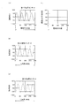
- the fourth-order error component included in the angle information after the offset has a waveform with a phase shift for each magnetic sensor 3, as shown in FIGS. 3 (a) to 3 (c). Therefore, by dividing the total value of these angle information by “3” and calculating the average value, the fourth-order error components can be canceled and reduced as shown in FIG.
- the rotation angle detector 1 Next, the rotation angle detector 1 according to the second embodiment will be described.
- symbol is used and the detail is abbreviate
- the position of the three magnetic sensors 3 has a phase difference in which the angle information output from the three magnetic sensors 3 differs by 120 degrees in electrical angle. The point which is set so that it may become equal intervals along the circumferential direction of the multipolar magnet ring 2 differs from 1st Embodiment.
- the angle information output from the three magnetic sensors 3 differs by 120 degrees in electrical angle.
- the first magnetic sensor 31 is disposed at a mechanical angle of 0 degrees
- the second magnetic sensor 32 is disposed at a mechanical angle of 120 degrees
- the third magnetic sensor 33 is disposed at a mechanical angle of 240 degrees.
- Other configurations are the same as those in the first embodiment.
- the rotation angle detector 1 for example, as shown in FIG. 5A, when the multipolar magnet ring 2 is eccentric, the mechanical angle obtained from the magnetic sensor 3 is as shown in FIG. As shown in FIG. 5, the first-order error component is included for the entire circumference of the mechanical angle, that is, for the mechanical angle of 0 to 360 degrees.
- the three magnetic sensors 3 are arranged at equal intervals, that is, at different positions by 120 degrees in mechanical angle. Therefore, as shown in FIG. 5C, the phase of the first-order error component included in the mechanical angle obtained from each magnetic sensor 3 can be shifted by 120 degrees. Therefore, by calculating the average value of the mechanical angles, as shown in FIG. 5D, the first order error can be canceled and the rotation angle can be detected with higher accuracy.
- the rotation angle detector 1 of the second embodiment in addition to the primary error component, it is possible to cancel error components of orders other than multiples of 3.
- the error component of the electrical angle in the first embodiment is a fourth-order error component, when the number of pole pairs is 4, it appears as a 16th-order error component around the entire mechanical angle. Therefore, it can be canceled because it is an order other than a multiple of 3.
- the first-order error component in the entire mechanical angle in addition to the fourth-order error component in the electrical angle (the 16th-order error component in the entire mechanical angle), the first-order error component in the entire mechanical angle. If included, the mechanical angle error component obtained from the second magnetic sensor 32 deviates from the mechanical angle error component obtained from the first magnetic sensor 31 by 120 degrees. Further, the mechanical angle error component obtained from the third magnetic sensor 33 is shifted by 240 degrees from the mechanical angle error component obtained from the first magnetic sensor 31. Therefore, as shown in FIGS. 6D and 6E, when the error components of the magnetic sensors 3 (31, 32, 33) are combined, both the first-order error component and the 16th-order error component are combined. Can be countered.
- the error component canceling effect can be applied to error components other than the orders listed so far (first order in mechanical angle, 16th order), and 2 in mechanical angle. It is also possible to cancel out the next error component, the second-order error component in electrical angle (the eighth-order error component in mechanical angle), and the like.
- the number of pole pairs of the multipolar magnet ring 2 is 4 has been described.
- the number of pole pairs differs from that of the three magnetic sensors 3 by 120 degrees in mechanical angle.
- the angle information output from the three magnetic sensors 3 may have a phase difference that differs by 120 degrees in electrical angle.
- the number of pole pairs for example, 4, 8, 10, 11, 13, 14, 16, 17, 19, 20, 22 can be employed.
- the number of magnetic sensors 3 constituting one magnetic sensor group is three has been shown, other configurations may be employed.
- the number when canceling an error component of an order other than a multiple of N (N is a natural number of 3 or more excluding 4), the number may be a number corresponding to the order of the error component, such as N magnetic sensors 3.
- the phase of the mechanical angle error component obtained from each magnetic sensor 3 can be shifted by 360 / N degrees.
- the number of pole pairs of the multipolar magnet ring 2 is assumed to be the number of pole pairs in which the angle information output from the N magnetic sensors 3 has a phase difference different by 360 / N degrees in electrical angle.
- the calculation unit 4 calculates an average value of mechanical angles obtained from the N magnetic sensors 3 and performs a calculation to obtain a detection value (true value) of the rotation angle of the multipolar magnet ring 2.
- the phase difference differs by 90 degrees, and it is difficult to reduce the fourth-order error component. Therefore, the present invention excludes this case (when N is 4).
- the third embodiment includes an abnormality occurrence determination unit 5 that determines whether an abnormality has occurred in any of N (N is a natural number of 3 or more excluding 4) magnetic sensors 3. Further points differ from the first embodiment. Also, the positions of the N magnetic sensors 3 are set to be equally spaced along the circumferential direction of the multipolar magnet ring 2 as in the second embodiment, that is, to be shifted by 120 degrees in mechanical angle. Has been. In the example of FIG. 7, N is set to 3.
- the abnormality occurrence determination unit 5 assumes a phase difference (120 degrees, 240 degrees) that is assumed in advance from the angle information output from the three magnetic sensors 3. Offset), the total value of the angle information after the offset is calculated, and based on the calculated total value, it is determined whether or not an abnormality has occurred in any of the three magnetic sensors 3.
- the total value of angle information after offset is three times the angle information output from the first magnetic sensor 31, three times the angle information output from the second magnetic sensor 32, and the third magnetic sensor. It is monitored whether or not it is equal to three times the angle information output from 33 (hereinafter also referred to as “3 ⁇ ⁇ , 3 ⁇ ⁇ and 3 ⁇ ⁇ ”).
- the total value of the angle information after the offset is 3 ⁇ ⁇ , 3 ⁇ ⁇ and 3 ⁇ equal to each of ⁇ .
- the total value is 3 ⁇ ⁇ , 3 as shown in FIGS. ⁇ Neither ⁇ nor 3 ⁇ ⁇ is equal. Therefore, when the abnormality occurrence determination unit 5 determines that the total value of the angle information output from the offset magnetic sensor 3 is not equal to any of 3 ⁇ ⁇ , 3 ⁇ ⁇ , and 3 ⁇ ⁇ , It is determined that an abnormality has occurred in any of the magnetic sensors 3. Thereby, it can be confirmed relatively easily that an abnormality has occurred in any of the three magnetic sensors.
- Other configurations are the same as those in the first embodiment.
- a configuration may further include an abnormality sensor determination unit 6 that determines a magnetic sensor 3 in which an abnormality has occurred from among N (N is a natural number of 3 or more excluding 4) magnetic sensors 3. Good.
- N is set to 3.
- the abnormality sensor determination unit 6 performs a phase difference (120 degrees, 240 degrees) preliminarily assumed from the angle information output from the three magnetic sensors 3. Offset degrees). Subsequently, based on the difference between the offset angle information corresponding to the two magnetic sensors 3 selected from the three magnetic sensors 3, the magnetic sensor 3 in which an abnormality has occurred is determined from the three magnetic sensors 3. To do.
- the output signal (angle information) ⁇ 1 of the first magnetic sensor 31 after the offset and the output signal (angle information) ⁇ 2 of the second magnetic sensor 32 are obtained. It is monitored whether the difference is smaller than a predetermined threshold and is substantially zero (including zero). Similarly, the difference between the output signal (angle information) ⁇ 2 of the second magnetic sensor 32 after the offset and the output signal (angle information) ⁇ 3 of the third magnetic sensor 33 is smaller than the threshold value and is almost zero. To monitor. Further, it is monitored whether the difference between the output signal ⁇ 3 of the third magnetic sensor 33 after the offset and the output signal ⁇ 1 of the first magnetic sensor 31 is smaller than the threshold value and is substantially zero.
- the rotation angle detector 1 may be configured to include at least two magnetic sensor groups.
- N for example, three
- magnetic sensors 3 constituting the magnetic sensor group are arranged in two lines in an IC package.
- a first system including first, second, and third magnetic sensors represented by reference numerals 31, 32, and 33, and first, second, and third expressions represented by reference numerals 31a, 32a, and 33a.
- a second system including a third magnetic sensor.
- the rotation angle detector 1 includes the power supply voltage Vcc1 and the ground voltage Gnd1 of the first to third magnetic sensors 31 to 33 of the first system, and the first to third magnetic sensors 31a to 33a of the second system.
- the power supply voltage Vcc2 and the ground voltage Gnd2 are separately provided.
- the arithmetic unit 4 determines abnormality of the magnetic sensor 3 constituting one of the two systems
- the angle information sign output from the three magnetic sensors 3 of the other system is used.
- the rotation angle (mechanical angle) of the multipolar magnet ring 2 is calculated.
- the occurrence of abnormality of the magnetic sensor 3 is performed using the above-described abnormality sensor determination unit 6 in each of the first system and the second system.
- a flag for specifying the magnetic sensor 3 in which the abnormality has occurred is set.
- the abnormality sensor determination unit 6 is provided in the calculation unit 4.
- an MCU (Micro Controller Unit) 7 determines which one of the first system magnetic sensor 3 and the second system magnetic sensor 3 has an abnormality based on the set flag. Subsequently, the rotation angle (mechanical angle) of the multipolar magnet ring 2 is determined by the MCU 7 using the angle information output from the three (N) magnetic sensors 3 of the system (normal system) in which no abnormality has occurred. calculate. Thereby, the detection function of a rotation angle can be continued using a normal system.
- the rotation angle detector 1 is disposed on each of the input shaft 9 and the output shaft 10.
- the multipolar magnet ring 2 of the rotation angle detector 1 on the input shaft 9 side is fixed coaxially with the input shaft 9 and rotates as the input shaft 9 rotates.
- the multipolar magnet ring 2 of the rotation angle detector 1 on the output shaft 10 side is fixed coaxially with the output shaft 10 and rotates with the rotation of the output shaft 10.
- the torsion angle calculation unit 11 calculates the difference between the rotation angle of the input shaft 9 and the rotation angle of the output shaft 10 detected by the rotation angle detector 1 as a torsion angle that is proportional to the torque. Thereby, the twist angle (torque) can be detected with higher accuracy.
- the motor output is calculated using the calculated twist angle. Control and assist steering operation. In this case, even if the multipolar magnet ring 2 is eccentric due to vibrations generated on the input shaft and the output shaft of the steering system as the vehicle travels, the rotation angle can be detected with higher accuracy. Therefore, the steering operation can be assisted with higher accuracy in the long term.
- Other configurations are the same as those in the first embodiment.
- the MCU 7 may be configured to add an IC determination function that enables the magnetic sensor 3 (sensor IC) to be determined to the communication function between the magnetic sensor 3 (sensor IC) and the MCU 7.
- the MCU 7 is configured to be able to designate an IC (magnetic sensor 3) to be communicated.
- the first common signal line 12 a that enables communication between the MCU 7 and the first system magnetic sensors 31, 32, 33 on the input shaft 9 side, and the second system magnetic sensor on the input shaft 9 side. 31a, 32a, 33a and the second common signal line 12b enabling the MCU 7 to communicate with each other.
- a third common signal line 12c that enables communication between the first system magnetic sensors 31, 32, 33 on the output shaft 10 side and the MCU 7, and a second system magnetic sensor 31a on the output shaft 10 side, 32a, 33a and the fourth common signal line 12d that enables the MCU 7 to properly communicate with each other.
- a fifth common signal line 12e for supplying the power supply voltage Vcc1 to the first to third magnetic sensors 31, 32, 33 of the first system and a sixth common signal line 12f for supplying the ground voltage Gnd1 are provided. Yes.
- a seventh common signal line 12g for supplying the power supply voltage Vcc2 to the first to third magnetic sensors 31a, 32a, 33a of the second system and an eighth common signal line 12h for supplying the ground voltage Gnd2 are provided. Yes.
- the first to third magnetic sensors 31, 32, and 33 of the first system and the first to third magnetic sensors 31a, 32a, and 33a of the second system are arranged on the substrate 13. Signal lines can be collected, and the number of signal lines can be reduced to eight.
- the configuration shown in FIG. 15 can be formed by three pairs of magnetic sensors (three on the input shaft 9 side and three on the output shaft 10 side), each including two systems as one package.
- each system is monitored and can function even if an abnormality occurs in one of the systems.
- the calculation of the torsion angle and the assist of the steering operation are continued.
- System monitoring can be continued.
- the magnetic sensor 3 may be provided with a magnetic pole counter function for counting magnetic poles. Thereby, the rotation of the input shaft 9 and the output shaft 10 can be counted.
- the magnetization direction of the multipolar magnet ring 2 was made into the outer diameter direction, the example which arrange
- the magnetization direction is not limited, and may be inner diameter magnetization, upper magnetization, or lower magnetization. This assembling and magnetic sensor 3 is arranged facing the magnetizing direction (magnetized surface).
- the magnetic sensor 3 uses a sensor in which one pole pair of the multipolar magnet ring 2 corresponds to an electrical angle of 360 degrees.
- other configurations may be adopted. it can.
- a sensor in which one pole of the multipolar magnet ring 2 corresponds to an electrical angle of 360 degrees may be used.
- the rotation angle detector 1 of the present invention can be applied to other than the magnetic circuit of the above embodiment.
Landscapes
- Physics & Mathematics (AREA)
- General Physics & Mathematics (AREA)
- Electromagnetism (AREA)
- Transmission And Conversion Of Sensor Element Output (AREA)
Abstract
回転角度検出器(1)は、周方向に沿って多極に磁化されている多極磁石リング(2)と、多極磁石リング(2)の周方向に沿って配置され、多極磁石リング(2)の回転に応じて、電気角で120度ずつ異なる位相差を有する角度情報を出力する3個の磁気センサ(3)からなる少なくとも一つの磁気センサ群と、一つの磁気センサ群を構成する3個の磁気センサ(3)から出力される角度情報に基づき多極磁石リング(2)の回転角度を算出する演算部(4)と、を備える。
Description
本発明は、回転角度検出器及びトルクセンサに関する。
従来、回転角度検出器としては、例えば、多極磁石リングと、多極磁石リングの周方向に沿って配置された複数の磁気センサとを備え、各磁気センサから得られる角度情報に基づき多極磁石リングの回転角度を算出するものがある(例えば、特許文献1、2参照)。
また、この特許文献1、2に記載の技術では、角度情報から3次の高調波成分を除去するようになっている。これにより、より正確な回転角度を算出可能となっている。
また、この特許文献1、2に記載の技術では、角度情報から3次の高調波成分を除去するようになっている。これにより、より正確な回転角度を算出可能となっている。
しかしながら、上記特許文献1、2に記載の技術では、3次の高調波成分(誤差成分)を除去できるものの、角度情報から4次の誤差成分を除去しきれない可能性がある。
本発明は、上記のような点に着目し、角度情報に含まれる4次の誤差成分を削減可能な回転角度検出器及びトルクセンサを提供することを目的とする。
本発明は、上記のような点に着目し、角度情報に含まれる4次の誤差成分を削減可能な回転角度検出器及びトルクセンサを提供することを目的とする。
上記課題を解決するために、本発明の一態様は、周方向に沿って多極に磁化されている多極磁石リングと、多極磁石リングの周方向に沿って配置され、多極磁石リングの回転に応じて、電気角で360/N(Nは4を除く3以上の自然数)度ずつ異なる位相差を有する角度情報を出力するN個の磁気センサからなる少なくとも一つの磁気センサ群と、一つの磁気センサ群を構成するN個の磁気センサから出力される角度情報に基づき多極磁石リングの回転角度を算出する演算部と、を備えることを特徴とする。
本発明の一態様によれば、各磁気センサの角度情報に含まれる4次の誤差成分の位相をずらすことができる。そのため、これらの角度情報を基に多極磁石リングの回転角度を算出することで、角度情報に含まれる4次の誤差成分を削減することができる。
以下、本発明の一実施形態について、図面を参照しつつ説明する。
なお、以下に示す実施形態は、本発明の技術的思想を具体化するための装置や方法を例示するものであって、本発明の技術的思想は、構成部品の形状、構造、配置等を下記のものに特定するものでない。本発明の技術的思想は、請求の範囲に記載された請求項が規定する技術的範囲内において、種々の変更を加えることができる。
なお、以下に示す実施形態は、本発明の技術的思想を具体化するための装置や方法を例示するものであって、本発明の技術的思想は、構成部品の形状、構造、配置等を下記のものに特定するものでない。本発明の技術的思想は、請求の範囲に記載された請求項が規定する技術的範囲内において、種々の変更を加えることができる。
(第1実施形態)
(構成)
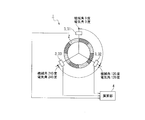
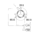
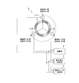
図1に示すように、第1実施形態の回転角度検出器1は、多極磁石リング2と、3個の磁気センサ3からなる少なくとも一つの磁気センサ群と、演算部4と、を備えている。図1の例では、3個の磁気センサ3からなる磁気センサ群の数は一つとなっている。
多極磁石リング2は、軸方向長さの短いリング状に形成され、周方向に沿って多極に磁化されている。各磁極の着磁方向は、外径向きとなっている。また、多極磁石リング2の極対数は、4つとなっている。さらに、4つの極対のうちの、予め定めた極対問(図1の例では、多極磁石リング2の最上部の極対間)に、機械角0度が設定されている。
(構成)
図1に示すように、第1実施形態の回転角度検出器1は、多極磁石リング2と、3個の磁気センサ3からなる少なくとも一つの磁気センサ群と、演算部4と、を備えている。図1の例では、3個の磁気センサ3からなる磁気センサ群の数は一つとなっている。
多極磁石リング2は、軸方向長さの短いリング状に形成され、周方向に沿って多極に磁化されている。各磁極の着磁方向は、外径向きとなっている。また、多極磁石リング2の極対数は、4つとなっている。さらに、4つの極対のうちの、予め定めた極対問(図1の例では、多極磁石リング2の最上部の極対間)に、機械角0度が設定されている。
一つの磁気センサ群を構成する3個の磁気センサ3のそれぞれは、多極磁石リング2の周方向に沿って、多極磁石リング2の外周に対向させて配置されている。3個の磁気センサ3のうち、第1の磁気センサ31は機械角0度の位置、第2の磁気センサ32は機械角30度の位置、第3の磁気センサ33は機械角60度の位置に配置されている。3個の磁気センサ3としては、多極磁石リング2の回転に応じて位相を変動させる正弦波信号の該位相を角度情報として出力する、互いに同一規格のセンサICが用いられている。例えば、多極磁石リング2の回転に応じて正弦波信号(現信号)を生成する正弦波信号生成部と、生成された正弦波信号の位相を出力する位相出力部と、からなるICを採用できる。
ここで、上記のように多極磁石リング2の極対数は4つであり、各磁気センサ3の位置は機械角で30度ずつずれている。そのため、3個の磁気センサ3から出力される角度情報は、電気角で120度ずつ異なる位相差を有することになる。例えば、第1の磁気センサ31から出力される角度情報が0度である場合、第2の磁気センサ32から出力される角度情報は120度、第3の磁気センサ33から出力される角度情報は240度となる。
また、磁気センサ3が配置されている各位置では、極対数が4であるため、多極磁石リング2の1回転中に4周期分の磁界が生成される。それゆえ、磁気センサ3のそれぞれは、多極磁石リング2の1回転中に4周期分の角度情報を生成して演算部4に出力する。
また、磁気センサ3が配置されている各位置では、極対数が4であるため、多極磁石リング2の1回転中に4周期分の磁界が生成される。それゆえ、磁気センサ3のそれぞれは、多極磁石リング2の1回転中に4周期分の角度情報を生成して演算部4に出力する。
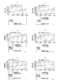
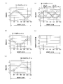
ここで、3個の磁気センサ3から出力される角度情報は、図2(a)~(c)に示すように、120度ずつずれている。そのため、演算部4は、まず、そのずれ量、つまり、一つの磁気センサ群を構成する3個の磁気センサ3から出力される角度情報の位相差分をオフセットする。具体的には、図2(d)~(f)に示すように、第1の磁気センサ31から出力される角度情報の座標系を基準とし、第2の磁気センサ32から出力される角度情報の座標系に120度分の座標を加算し、第3の磁気センサ33から出力される角度情報の座標系に240度分の座標を加算して、三つの座標系をあわせる。続いて、演算部4は、オフセット後の角度情報の合計値を算出し、算出した合計値を「3」で除算して角度情報の平均値とする。そして、算出した平均値を、角度情報(電気角)の検出値(真値)として、この検出値(真値)に基づき、多極磁石リング2の回転角度(機械角)を算出する。
(作用その他)
一般に、多極磁石リング2と磁気センサ3との組み合わせで検出される角度情報は、原信号が正弦波であれば、角度誤差を小さくすることができる。しかしながら、このような角度情報には、図2(a)~(c)に示すように、電気角1周期分あたり4次の誤差成分が重畳しやすい。この4次の誤差成分の重畳が、高精度な角度情報を阻む主要因となる。
この4次の誤差が重畳する原因は、磁気センサ3が検出する原信号に3次や5次の高調波成分が重畳しやすいためであり、改善には着磁精度や素子配置精度、検出素子特性の調整等の精密な作業が必要とされる。また、磁気センサ3を多数配置することで誤差を削減することも考えられるが、磁気センサ3の数が増加するためコストアップの要因となる。
また、3次の高調波成分の削減にはいわゆる三相二相変換の技術を用いることができる。しかしながら、この三相二相変換の技術は、5次の高調波成分の削減に寄与しない。それゆえ、3次の高調波に比べ、5次の高調波成分は小さいが、誤差の要因として残る。
一般に、多極磁石リング2と磁気センサ3との組み合わせで検出される角度情報は、原信号が正弦波であれば、角度誤差を小さくすることができる。しかしながら、このような角度情報には、図2(a)~(c)に示すように、電気角1周期分あたり4次の誤差成分が重畳しやすい。この4次の誤差成分の重畳が、高精度な角度情報を阻む主要因となる。
この4次の誤差が重畳する原因は、磁気センサ3が検出する原信号に3次や5次の高調波成分が重畳しやすいためであり、改善には着磁精度や素子配置精度、検出素子特性の調整等の精密な作業が必要とされる。また、磁気センサ3を多数配置することで誤差を削減することも考えられるが、磁気センサ3の数が増加するためコストアップの要因となる。
また、3次の高調波成分の削減にはいわゆる三相二相変換の技術を用いることができる。しかしながら、この三相二相変換の技術は、5次の高調波成分の削減に寄与しない。それゆえ、3次の高調波に比べ、5次の高調波成分は小さいが、誤差の要因として残る。
これに対し、第1実施形態の回転角度検出器1では、図1、図2(a)~(c)に示すように、一つの磁気センサ群を構成する3個の磁気センサ3を、多極磁石リング2の回転に応じて電気角で120度ずつ異なる位相差を有する角度情報を出力するように配置した。それゆえ、各磁気センサ3の角度情報に含まれる4次の誤差成分の位相をずらすことができる。そのため、これらの角度情報を基に多極磁石リング2の回転角度を算出することで、磁気センサ3の角度情報に含まれる4次の誤差成分を削減することができる。
また、第1実施形態の回転角度検出器1では、磁気センサ3から出力される角度情報の位相差分をオフセットするようにした。それゆえ、オフセット後の角度情報に含まれる4次の誤差成分は、図3(a)~(c)に示すように、磁気センサ3毎に位相のずれた波形となる。それゆえ、これらの角度情報の合計値を「3」で除算して平均値を算出することで、図3(d)に示すように4次の誤差成分を互いに打ち消して削減することができる。
また、第1実施形態の回転角度検出器1では、磁気センサ3から出力される角度情報の位相差分をオフセットするようにした。それゆえ、オフセット後の角度情報に含まれる4次の誤差成分は、図3(a)~(c)に示すように、磁気センサ3毎に位相のずれた波形となる。それゆえ、これらの角度情報の合計値を「3」で除算して平均値を算出することで、図3(d)に示すように4次の誤差成分を互いに打ち消して削減することができる。
(第2実施形態)
次に、第2実施形態に係る回転角度検出器1について説明する。なお、第1実施形態と同様な構成等については同一の符号を使用して、その詳細は省略する。
第2実施形態は、図4に示すように、3個の磁気センサ3の位置は、3個の磁気センサ3から出力される角度情報が電気角で120度ずつ異なる位相差を有し、また多極磁石リング2の周方向に沿って等間隔となるように設定されている点が、第1実施形態と異なる。図4の例では、第1の磁気センサ31は機械角0度の位置、第2の磁気センサ32は機械角120度の位置、第3の磁気センサ33は機械角240度の位置に配置されている。
なお、その他の構成は、第1実施形態と同様である。
次に、第2実施形態に係る回転角度検出器1について説明する。なお、第1実施形態と同様な構成等については同一の符号を使用して、その詳細は省略する。
第2実施形態は、図4に示すように、3個の磁気センサ3の位置は、3個の磁気センサ3から出力される角度情報が電気角で120度ずつ異なる位相差を有し、また多極磁石リング2の周方向に沿って等間隔となるように設定されている点が、第1実施形態と異なる。図4の例では、第1の磁気センサ31は機械角0度の位置、第2の磁気センサ32は機械角120度の位置、第3の磁気センサ33は機械角240度の位置に配置されている。
なお、その他の構成は、第1実施形態と同様である。
(作用その他)
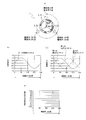
通常、回転角度検出器1では、例えば、図5(a)に示すように、多極磁石リング2が偏芯している場合、磁気センサ3から得られる機械角には、図5(b)に示すように、機械角全周、つまり、機械角0度~360度に対し1次の誤差成分が含まれることになる。
これに対し、第2実施形態の回転角度検出器1は、等間隔となるように、つまり、機械角で120度ずつ異なる位置に3個の磁気センサ3を配置した。それゆえ、図5(c)に示すように、各磁気センサ3から得られる機械角が含む1次の誤差成分の位相を120度ずつずらすことができる。そのため、機械角の平均値を算出することで、図5(d)に示すように、1次の誤差を打ち消すことができ、回転角度をより高精度に検出できる。
通常、回転角度検出器1では、例えば、図5(a)に示すように、多極磁石リング2が偏芯している場合、磁気センサ3から得られる機械角には、図5(b)に示すように、機械角全周、つまり、機械角0度~360度に対し1次の誤差成分が含まれることになる。
これに対し、第2実施形態の回転角度検出器1は、等間隔となるように、つまり、機械角で120度ずつ異なる位置に3個の磁気センサ3を配置した。それゆえ、図5(c)に示すように、各磁気センサ3から得られる機械角が含む1次の誤差成分の位相を120度ずつずらすことができる。そのため、機械角の平均値を算出することで、図5(d)に示すように、1次の誤差を打ち消すことができ、回転角度をより高精度に検出できる。
ここで、第2実施形態の回転角度検出器1では、1次の誤差成分の他にも、3の倍数以外の次数の誤差成分を打ち消すことができる。例えば、第1実施形態の電気角の誤差成分は、4次の誤差成分であるため、極対数が4である場合、機械角全周で16次の誤差成分となって現れる。それゆえ、3の倍数以外の次数であるため、打ち消すことができる。
例えば、図6(a)~(c)に示すように、電気角で4次の誤差成分(機械角全周で16次の誤差成分)に加え、機械角全周で1次の誤差成分が含まれる場合、第2の磁気センサ32から得られる機械角の誤差成分は、第1の磁気センサ31から得られる機械角の誤差成分から120度ずれる。また、第3の磁気センサ33から得られる機械角の誤差成分は、第1の磁気センサ31から得られる機械角の誤差成分から240度ずれる。それゆえ、図6(d)、(e)に示すように、各磁気センサ3(31、32、33)の誤差成分を合成すると、1次の誤差成分と16次の誤差成分との両方を打ち消すことができる。
また、第2実施形態の回転角度検出器1では、誤差成分の打ち消し効果は、ここまでに挙げた次数(機械角で1次、16次)以外の誤差成分にも適用でき、機械角で2次の誤差成分や電気角で2次の誤差成分(機械角で8次の誤差成分)等も打ち消すことができる。
また、第2実施形態の回転角度検出器1では、誤差成分の打ち消し効果は、ここまでに挙げた次数(機械角で1次、16次)以外の誤差成分にも適用でき、機械角で2次の誤差成分や電気角で2次の誤差成分(機械角で8次の誤差成分)等も打ち消すことができる。
なお、第1実施形態、第2実施形態では、多極磁石リング2の極対数を4とする場合について説明したが、極対数は、3個の磁気センサ3を機械角で120度ずつ異なる位置に配置した場合に、3個の磁気センサ3から出力される角度情報が電気角で120度ずつ異なる位相差を有する構成であればよい。極対数としては、例えば、4、8、10、11、13、14、16、17、19、20、22等を採用することができる。
また、一つの磁気センサ群を構成する磁気センサ3を3個とする例を示したが、他の構成を採用することもできる。例えば、N(Nは4を除く3以上の自然数)の倍数以外の次数の誤差成分を打ち消す場合には、磁気センサ3をN個とする等、誤差成分の次数に応じた個数としてもよい。この場合、各磁気センサ3から得られる機械角の誤差成分の位相を360/N度ずつずらすことができる。また、多極磁石リング2の極対数は、N個の磁気センサ3から出力される角度情報が電気角で360/N度ずつ異なる位相差を有する極対数とするものとする。そして、演算部4では、N個の磁気センサ3から得られる機械角の平均値を算出して、多極磁石リング2の回転角度の検出値(真値)とする演算を行う。なお、磁気センサ3が4個の場合、位相差が90度ずつ異なることになり、4次の誤差成分を削減することが難しいので、本発明からこの場合(Nが4の場合)を除くものとする。
(第3実施形態)
次に、第3実施形態に係る回転角度検出器1について説明する。なお、第1実施形態と同様な構成等については同一の符号を使用して、その詳細は省略する。
第3実施形態は、図7に示すように、N(Nは4を除く3以上の自然数)個の磁気センサ3のいずれかに異常が発生したか否かを判定する異常発生判定部5を更に備える点が、第1実施形態と異なる。また、N個の磁気センサ3の位置が、第2実施形態と同様に、多極磁石リング2の周方向に沿って等間隔となるように、つまり、機械角で120度ずつずれるように設定されている。なお、図7の例では、Nは3に設定されている。
次に、第3実施形態に係る回転角度検出器1について説明する。なお、第1実施形態と同様な構成等については同一の符号を使用して、その詳細は省略する。
第3実施形態は、図7に示すように、N(Nは4を除く3以上の自然数)個の磁気センサ3のいずれかに異常が発生したか否かを判定する異常発生判定部5を更に備える点が、第1実施形態と異なる。また、N個の磁気センサ3の位置が、第2実施形態と同様に、多極磁石リング2の周方向に沿って等間隔となるように、つまり、機械角で120度ずつずれるように設定されている。なお、図7の例では、Nは3に設定されている。
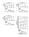
具体的には、異常発生判定部5は、図2(a)~(f)に示すように、3個の磁気センサ3から出力される角度情報から予め想定される位相差(120度、240度)分をオフセットし、オフセット後の角度情報の合計値を算出し、算出した合計値に基づき3個の磁気センサ3のいずれかに異常が発生したか否かを判定する。例えば、オフセット後の角度情報の合計値が、第1の磁気センサ31から出力される角度情報の3倍、第2の磁気センサ32から出力される角度情報の3倍、及び第3の磁気センサ33から出力される角度情報の3倍(以下、「3・α、3・β及び3・γ」とも呼ぶ)と等しいか否かを監視する。
ここで、3個の磁気センサ3に機能失陥がない場合、図8(a)~(d)に示すように、オフセット後の角度情報の合計値が3・α、3・β及び3・γのそれぞれと等しくなる。一方、一つまたは二つの磁気センサ3に機能失陥が発生し、角度情報がゼロ等になった場合、図9(a)、(b)に示すように、合計値が3・α、3・β及び3・γのいずれとも等しくならない。それゆえ、異常発生判定部5は、オフセット後の磁気センサ3から出力される角度情報の合計値が3・α、3・β及び3・γのいずれとも等しくないと判定した場合に、3個の磁気センサ3のいずれかに異常が発生したと判定する。これにより、3個の磁気センサのいずれかに異常が発生したことを比較的容易に確認することができる。
なお、その他の構成は、第1実施形態と同様である。
なお、その他の構成は、第1実施形態と同様である。
(変形例)
(1)なお、第3実施形態では、異常発生判定部5が、N個の磁気センサ3のいずれかに異常が発生したかを判定する例を示したが、他の構成を採用することもできる。例えば、図10に示すように、N(Nは4を除く3以上の自然数)個の磁気センサ3のうちから異常が発生した磁気センサ3を判定する異常センサ判定部6を更に備える構成としてもよい。なお、図10の例では、Nは3に設定されている。具体的には、異常センサ判定部6は、図2(a)~(f)に示すように、3個の磁気センサ3から出力される角度情報から予め想定される位相差(120度、240度)分をオフセットする。続いて、3個の磁気センサ3から選択される二つの磁気センサ3に対応するオフセット後の角度情報同士の差分に基づき、3個の磁気センサ3のうちから異常が発生した磁気センサ3を判定する。
(1)なお、第3実施形態では、異常発生判定部5が、N個の磁気センサ3のいずれかに異常が発生したかを判定する例を示したが、他の構成を採用することもできる。例えば、図10に示すように、N(Nは4を除く3以上の自然数)個の磁気センサ3のうちから異常が発生した磁気センサ3を判定する異常センサ判定部6を更に備える構成としてもよい。なお、図10の例では、Nは3に設定されている。具体的には、異常センサ判定部6は、図2(a)~(f)に示すように、3個の磁気センサ3から出力される角度情報から予め想定される位相差(120度、240度)分をオフセットする。続いて、3個の磁気センサ3から選択される二つの磁気センサ3に対応するオフセット後の角度情報同士の差分に基づき、3個の磁気センサ3のうちから異常が発生した磁気センサ3を判定する。
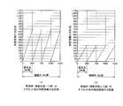
より具体的には、図11(a)に示すように、オフセット後の第1の磁気センサ31の出力信号(角度情報)θ1と第2の磁気センサ32の出力信号(角度情報)θ2との差分が予め定めたしきい値より小さく、ほぼゼロ(ゼロを含む)であるかを監視する。同様に、オフセット後の第2の磁気センサ32の出力信号(角度情報)θ2と第3の磁気センサ33の出力信号(角度情報)θ3との差分がしきい値より小さく、ほぼゼロであるかを監視する。また、オフセット後の第3の磁気センサ33の出力信号θ3と第1の磁気センサ31の出力信号θ1との差分がしきい値より小さく、ほぼゼロであるかを監視する。
ここで、3個の磁気センサ3に機能失陥がない場合、各差分がそれぞれほぼゼロになるが、一つの磁気センサ3に機能失陥が発生し、角度情報がゼロ等になった場合、機能失陥の磁気センサ3の出力信号(角度情報)との差分のみがゼロから外れた値となる。それゆえ、異常センサ判定部6は、ゼロでない組み合わせがあると判定した場合に、ゼロでない組み合わせに基づき、3個の磁気センサ3のうちから異常が発生した磁気センサ3を判定する。これにより、異常が発生した磁気センサ3を比較的容易に確認することができる。
図11(b)の例では、第1の磁気センサ31が機能失陥した揚合には、第2の磁気センサ32の出力信号(角度情報)θ2と第3の磁気センサ33の出力信号(角度情報)θ3との差分がゼロとなるため、第1の磁気センサ31が機能失陥したことを判別できる。
図11(b)の例では、第1の磁気センサ31が機能失陥した揚合には、第2の磁気センサ32の出力信号(角度情報)θ2と第3の磁気センサ33の出力信号(角度情報)θ3との差分がゼロとなるため、第1の磁気センサ31が機能失陥したことを判別できる。
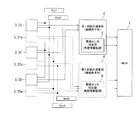
(2)また、例えば、図12に示すように、回転角度検出器1は、磁気センサ群を少なくとも2系統備える構成としてもよい。例えば、磁気センサ群を構成するN個(例えば3個)の磁気センサ3を、ICパッケージ内に絶縁して2系統配置する。図12の例では、符号31、32、33で表される第1、第2及び第3の磁気センサを含む第1系統と、符号31a、32a、33aで表される第1、第2及び第3の磁気センサを含む第2系統とを有している。また、回転角度検出器1には、第1系統の第1~第3の磁気センサ31~33の電源電圧Vcc1、グランド電圧Gnd1と、第2系統の第1~第3の磁気センサ31a~33aの電源電圧Vcc2、グランド電圧Gnd2とのそれぞれが別々に設けられている。
この場合、演算部4は、2系統のうちの、一方の系統を構成する磁気センサ3の異常を判定すると、他方の系統の3個の磁気センサ3から出力される角度情報号を用いて、多極磁石リング2の回転角度(機械角)を算出する。図12の例では、第1系統及び第2系統のそれぞれで、上記した異常センサ判定部6を用いて磁気センサ3の異常の発生の判定(角度情報監視)を行っている。この角度情報監視では、磁気センサ3に異常が発生したと判定したときに、異常が発生した磁気センサ3を特定するためのフラグをセット状態とする。なお、図12の例では、異常センサ判定部6が演算部4内に設けられている。
そして、MCU(Micro Controller Unit)7で、セット状態とされたフラグを基に第1系統の磁気センサ3と第2系統の磁気センサ3とのいずれに異常が発生したのかを判定する。続いて、MCU7で、異常が発生していない系統(正常系統)の3個(N個)の磁気センサ3から出力される角度情報を用いて多極磁石リング2の回転角度(機械角)を算出する。これにより、正常系統を用いて、回転角度の検出機能を継続することができる。
(第4実施形態)
次に、第4実施形態に係る回転角度検出器1について説明する。なお、第1実施形態と同様な構成等については同一の符号を使用して、その詳細は省略する。
第4実施形態では、図13に示すように、二つの回転角度検出器1と、捩れ角演算部11とを用い、トーションバーを介して連結された入力軸9と出力軸10との捩れ角を検出するトルクセンサ8を構成する点が、第1実施形態と異なる。また、3個の磁気センサ3の位置が、第2実施形態及び第3実施形態と同様に、多極磁石リング2の周方向に沿って等間隔となるように、つまり、機械角で120度ずつずれるように設定されている。
次に、第4実施形態に係る回転角度検出器1について説明する。なお、第1実施形態と同様な構成等については同一の符号を使用して、その詳細は省略する。
第4実施形態では、図13に示すように、二つの回転角度検出器1と、捩れ角演算部11とを用い、トーションバーを介して連結された入力軸9と出力軸10との捩れ角を検出するトルクセンサ8を構成する点が、第1実施形態と異なる。また、3個の磁気センサ3の位置が、第2実施形態及び第3実施形態と同様に、多極磁石リング2の周方向に沿って等間隔となるように、つまり、機械角で120度ずつずれるように設定されている。
具体的には、入力軸9と出力軸10とのそれぞれに回転角度検出器1を配置する。入力軸9側の回転角度検出器1の多極磁石リング2は、入力軸9と同軸に固定され、入力軸9の回転に伴って回転する。また、出力軸10側の回転角度検出器1の多極磁石リング2は、出力軸10と同軸に固定され、出力軸10の回転に伴って回転する。これにより、回転角度検出器1のそれぞれは、入力軸9の回転角度と出力軸10の回転角度とを検出する。
そして、捩れ角演算部11は、回転角度検出器1で検出された入力軸9の回転角度と出力軸10の回転角度との差分を、トルクと比例関係にある捩れ角として算出する。これにより、より高精度に捩れ角(トルク)を検出できる。また、電動パワーステアリング装置に適用し、入力軸9と出力軸10とのそれぞれとして、車両の操舵系の入力軸と出力軸とを用いた場合、算出した捩れ角を用いて、モータの出力を制御し、ハンドル操作をアシストすることができる。この場合、車両の走行に伴い操舵系の入力軸と出力軸とに発生する振動により、多極磁石リング2が偏芯したとしても、回転角度をより高精度に検出できる。そのため、ハンドル操作のアシストを、長期的により高精度に行うことができる。
なお、その他の構成は、第1実施形態と同様である。
なお、その他の構成は、第1実施形態と同様である。
(変形例)
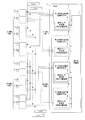
(1)なお、回転角度検出器1としては、図14に示すように、第3実施形態及びその変形例に記載の、磁気センサ3の異常を検出可能な回転角度検出器1を用いる構成としてもよい。図14の例では、第1系統及び第2系統の演算部4と捩れ角演算部11とがMCU7内に設けられており、さらに、異常センサ判定部6が演算部4内に設けられている。
(1)なお、回転角度検出器1としては、図14に示すように、第3実施形態及びその変形例に記載の、磁気センサ3の異常を検出可能な回転角度検出器1を用いる構成としてもよい。図14の例では、第1系統及び第2系統の演算部4と捩れ角演算部11とがMCU7内に設けられており、さらに、異常センサ判定部6が演算部4内に設けられている。
(2)また、例えば、MCU7は、磁気センサ3(センサIC)とMCU7との通信機能に磁気センサ3(センサIC)を判別可能とするIC判別機能を付加する構成としてもよい。この場合、MCU7が、通信したいIC(磁気センサ3)を指定可能な構成とする。
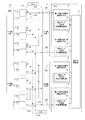
図15の例では、入力軸9側の第1系統の磁気センサ31、32、33とMCU7とを通信可能とする第1の共通信号線12aと、入力軸9側の第2系統の磁気センサ31a、32a、33aとMCU7とを通信可能とする第2の共通信号線12bとを備えている。
また同様に、出力軸10側の第1系統の磁気センサ31、32、33とMCU7とを通信可能とする第3の共通信号線12cと、出力軸10側の第2系統の磁気センサ31a、32a、33aとMCU7とを適信可能とする第4の共通信号線12dとを備えている。
図15の例では、入力軸9側の第1系統の磁気センサ31、32、33とMCU7とを通信可能とする第1の共通信号線12aと、入力軸9側の第2系統の磁気センサ31a、32a、33aとMCU7とを通信可能とする第2の共通信号線12bとを備えている。
また同様に、出力軸10側の第1系統の磁気センサ31、32、33とMCU7とを通信可能とする第3の共通信号線12cと、出力軸10側の第2系統の磁気センサ31a、32a、33aとMCU7とを適信可能とする第4の共通信号線12dとを備えている。
さらに、第1系統の第1~第3の磁気センサ31、32、33に電源電圧Vcc1を供給する第5の共通信号線12e、グランド電圧Gnd1を供給する第6の共通信号線12fを備えている。また、第2系統の第1~第3の磁気センサ31a、32a、33aに電源電圧Vcc2を供給する第7の共通信号線12g、グランド電圧Gnd2を供給する第8の共通信号線12hを備えている。このような構成により、第1系統の第1~第3の磁気センサ31、32、33や、第2系統の第1~第3の磁気センサ31a、32a、33aが配置された基板13上で信号線を纏めることができ、信号線の本数を8本に省線化できる。
図15の構成は、二つの系統を1パッケージとした合計6個(入力軸9側に3個、出力軸10側に3個)の磁気センサ3対で形成できる。また、図15の例では、各系統を監視し、一方の系統に異常が発生しても機能することができ、捩れ角の算出及びハンドル操作のアシストを継続し、さらに、異常発生後の各系統の監視を継続することができる。
図15の構成は、二つの系統を1パッケージとした合計6個(入力軸9側に3個、出力軸10側に3個)の磁気センサ3対で形成できる。また、図15の例では、各系統を監視し、一方の系統に異常が発生しても機能することができ、捩れ角の算出及びハンドル操作のアシストを継続し、さらに、異常発生後の各系統の監視を継続することができる。
(3)また、磁気センサ3に磁極をカウントする磁極カウンタ機能をもたせるようにしてもよい。これにより、入力軸9や出力軸10の回転の計数を可能とすることができる。
(4)さらに、上記実施形態では、多極磁石リング2の着磁方向を外径向きとすると共に、磁気センサ3を多極磁石リング2の外周に対向させて配置する例を示したが、他の構成を採用することもできる。例えば、着磁方向に制限はなく、内径着磁、上側着磁、下側着磁としてもよい。この揚合、磁気センサ3を着磁方向(着磁面)に対向させて配置する。
(5)また、上記実施形態では、磁気センサ3として、多極磁石リング2の1極対が電気角360度分に対応するセンサを用いる例を示したが、他の構成を採用することもできる。例えば多極磁石リング2の1極が電気角360度分に対応するセンサを用いてもよい。 なお、本発明の回転角度検出器1は、上記実施形態の磁気回路以外にも適用できる。
(4)さらに、上記実施形態では、多極磁石リング2の着磁方向を外径向きとすると共に、磁気センサ3を多極磁石リング2の外周に対向させて配置する例を示したが、他の構成を採用することもできる。例えば、着磁方向に制限はなく、内径着磁、上側着磁、下側着磁としてもよい。この揚合、磁気センサ3を着磁方向(着磁面)に対向させて配置する。
(5)また、上記実施形態では、磁気センサ3として、多極磁石リング2の1極対が電気角360度分に対応するセンサを用いる例を示したが、他の構成を採用することもできる。例えば多極磁石リング2の1極が電気角360度分に対応するセンサを用いてもよい。 なお、本発明の回転角度検出器1は、上記実施形態の磁気回路以外にも適用できる。
以上、本願が優先権を主張する日本国特許出願2016-142827(2016年7月20日出願)の全内容は、参照により本開示の一部をなす。
ここでは、限られた数の実施形態を参照しながら説明したが、権利範囲はそれらに限定されるものではなく、上記の開示に基づく各実施形態の改変は当業者にとって自明なことである。
ここでは、限られた数の実施形態を参照しながら説明したが、権利範囲はそれらに限定されるものではなく、上記の開示に基づく各実施形態の改変は当業者にとって自明なことである。
1 回転角度検出器
2 多極磁石リング
3 磁気センサ
4 演算部
5 異常発生判定部
6 異常センサ判定部
7 MCU
8 トルクセンサ
9 入力軸
10 出力帥
11 捩れ角演算部
31、31a 第1の磁気センサ
32、32a 第2の磁気センサ
33、33a 第3の磁気センサ
2 多極磁石リング
3 磁気センサ
4 演算部
5 異常発生判定部
6 異常センサ判定部
7 MCU
8 トルクセンサ
9 入力軸
10 出力帥
11 捩れ角演算部
31、31a 第1の磁気センサ
32、32a 第2の磁気センサ
33、33a 第3の磁気センサ
Claims (10)
- 周方向に沿って多極に磁化されている多極磁石リングと、
前記多極磁石リングの周方向に沿って配置され、前記多極磁石リングの回転に応じて、電気角で360/N(Nは4を除く3以上の自然数)度ずつ異なる位相差を有する角度情報を出力するN個の磁気センサからなる少なくとも一つの磁気センサ群と、
一つの前記磁気センサ群を構成するN個の磁気センサから出力される角度情報に基づき前記多極磁石リングの回転角度を算出する演算部と、を備えることを特徴とする回転角度検出器。 - 前記演算部は、一つの前記磁気センサ群を構成するN個の磁気センサから出力される角度情報の平均値を算出し、算出した平均値に基づき前記回転角度を算出することを特徴とする請求項1に記載の回転角度検出器。
- 前記演算部は、一つの前記磁気センサ群を構成するN個の磁気センサから出力される角度情報の前記位相差分をオフセットし、オフセット後の角度情報の合計値を算出し、算出した合計値をNで除算して前記平均値とすることを特徴とする請求項2に記載の回転角度検出器。
- 前記磁気センサは、前記多極磁石リングの周方向に沿って等間隔に配置されていることを特徴とする請求項1から3のいずれか1項に記載の回転角度検出器。
- 前記N個の磁気センサから出力される角度情報から前記位相差分をオフセットし、オフセット後の角度情報の合計値を算出し、算出した合計値に基づき前記N個の磁気センサのいずれかに異常が発生したか否かを判定する異常発生判定部を備えることを特徴とする請求項1から4のいずれか1項に記載の回転角度検出器。
- 前記N個の磁気センサから出力される角度情報から前記位相差分をオフセットし、オフセット後の角度情報のうち、前記N個の磁気センサから選択される二つの磁気センサに対応するオフセット後の角度情報同士の差分に基づき、前記N個の磁気センサのうちから異常が発生した磁気センサを判定する異常センサ判定部を備えることを特徴とする請求項1から5のいずれか1項に記載の回転角度検出器。
- 前記磁気センサ群を少なくとも2系統備え、
前記演算部は、前記2系統の一方の系統を構成する磁気センサの異常を判定すると、他方の系統の前記N個の磁気センサから出力される角度情報を用いて前記回転角度を算出することを特徴とする請求項5または6に記載の回転角度検出器。 - Nは、3であることを特徴とする請求項1から7のいずれか1項に記載の回転角度検出器。
- トーションバーを介して連結された入力軸と出力軸とのそれぞれに請求項1から8のいずれか1項に記載の回転角度検出器を配置し、前記入力軸の回転角度と前記出力軸の回転角度とを検出し、前記回転角度検出器で検出された前記入力軸の回転角度と前記出力軸の回転角度との差分を捩れ角として算出することを特徴とするトルクセンサ。
- 前記入力軸と前記出力軸のそれぞれは、車両の操舵系の入力軸と出力軸であることを特徴とする請求項9に記載のトルクセンサ。
Priority Applications (4)
| Application Number | Priority Date | Filing Date | Title |
|---|---|---|---|
| EP17830665.0A EP3396327B1 (en) | 2016-07-20 | 2017-04-19 | Rotation angle detector and torque sensor |
| CN201780020895.7A CN108885124A (zh) | 2016-07-20 | 2017-04-19 | 旋转角度检测器和扭矩传感器 |
| JP2018502442A JP6319538B1 (ja) | 2016-07-20 | 2017-04-19 | 回転角度検出器及びトルクセンサ |
| US16/073,870 US20190041240A1 (en) | 2016-07-20 | 2017-04-19 | Rotation Angle Detector and Torque Sensor |
Applications Claiming Priority (2)
| Application Number | Priority Date | Filing Date | Title |
|---|---|---|---|
| JP2016-142827 | 2016-07-20 | ||
| JP2016142827 | 2016-07-20 |
Publications (1)
| Publication Number | Publication Date |
|---|---|
| WO2018016145A1 true WO2018016145A1 (ja) | 2018-01-25 |
Family
ID=60992057
Family Applications (1)
| Application Number | Title | Priority Date | Filing Date |
|---|---|---|---|
| PCT/JP2017/015716 Ceased WO2018016145A1 (ja) | 2016-07-20 | 2017-04-19 | 回転角度検出器及びトルクセンサ |
Country Status (5)
| Country | Link |
|---|---|
| US (1) | US20190041240A1 (ja) |
| EP (1) | EP3396327B1 (ja) |
| JP (1) | JP6319538B1 (ja) |
| CN (1) | CN108885124A (ja) |
| WO (1) | WO2018016145A1 (ja) |
Cited By (3)
| Publication number | Priority date | Publication date | Assignee | Title |
|---|---|---|---|---|
| JP2018077096A (ja) * | 2016-11-08 | 2018-05-17 | 日本精工株式会社 | 回転角度検出器、トルクセンサ、モータ駆動制御装置、電動パワーステアリング装置及び車両 |
| JP2020153806A (ja) * | 2019-03-20 | 2020-09-24 | Tdk株式会社 | 回転角度検出装置 |
| JP2020159993A (ja) * | 2019-03-28 | 2020-10-01 | 株式会社デンソー | 検出ユニット |
Families Citing this family (3)
| Publication number | Priority date | Publication date | Assignee | Title |
|---|---|---|---|---|
| WO2019216235A1 (ja) * | 2018-05-11 | 2019-11-14 | 株式会社三共製作所 | 角度検出器 |
| CN110542500B (zh) * | 2019-06-26 | 2024-12-20 | 南京华敏电子有限公司 | 一种采用轴向充磁磁环的扭矩传感器 |
| US12480755B2 (en) * | 2021-05-31 | 2025-11-25 | Nidec Corporation | Angle detection method and angle detection device |
Citations (4)
| Publication number | Priority date | Publication date | Assignee | Title |
|---|---|---|---|---|
| JP2011220848A (ja) * | 2010-04-09 | 2011-11-04 | Jtekt Corp | 回転角検出装置 |
| JP2012122963A (ja) * | 2010-12-10 | 2012-06-28 | Jtekt Corp | 回転角検出装置、トルク検出装置、及び電動パワーステアリング装置 |
| JP2012149909A (ja) * | 2011-01-17 | 2012-08-09 | Jtekt Corp | 回転角検出装置 |
| JP2013101023A (ja) * | 2011-11-08 | 2013-05-23 | Nikon Corp | 位置検出装置、及び駆動装置 |
Family Cites Families (12)
| Publication number | Priority date | Publication date | Assignee | Title |
|---|---|---|---|---|
| US4660021A (en) * | 1983-03-25 | 1987-04-21 | Leiby Robert W | Method and apparatus for reducing crosstalk effects upon phase measurement |
| JP2001012967A (ja) * | 1999-04-28 | 2001-01-19 | Asahi Optical Co Ltd | エンコーダおよび磁気式エンコーダを搭載した測量機 |
| US6926115B2 (en) * | 2002-07-31 | 2005-08-09 | Hitachi Cable, Ltd. | Angle sensor, angle-torque sensor and electric power steering unit using same |
| WO2005021359A1 (ja) * | 2003-08-28 | 2005-03-10 | Nsk Ltd. | 電動パワーステアリング装置の制御装置 |
| JP4858855B2 (ja) * | 2006-11-21 | 2012-01-18 | 日立金属株式会社 | 回転角度検出装置および回転機 |
| JP4995605B2 (ja) * | 2007-03-16 | 2012-08-08 | オークマ株式会社 | 回転型アブソリュートエンコーダの異常検出装置 |
| WO2012025777A1 (en) * | 2010-08-24 | 2012-03-01 | Aktiebolaget Skf | A method and a system for determining the angular position of a rotary element, and a bearing including such a system |
| JP2012189376A (ja) * | 2011-03-09 | 2012-10-04 | Jtekt Corp | 回転角検出装置およびトルク検出装置 |
| US9627936B2 (en) * | 2011-12-23 | 2017-04-18 | Mitsubishi Electric Corporation | Permanent magnet motor |
| JP5675700B2 (ja) * | 2012-05-25 | 2015-02-25 | 株式会社日本自動車部品総合研究所 | トルクセンサ |
| GB2505226A (en) * | 2012-08-23 | 2014-02-26 | Melexis Technologies Nv | Arrangement, method and sensor for measuring an absolute angular position using a multi-pole magnet |
| JP6083428B2 (ja) * | 2014-12-16 | 2017-02-22 | トヨタ自動車株式会社 | 車両の電動パワーステアリング装置 |
-
2017
- 2017-04-19 EP EP17830665.0A patent/EP3396327B1/en active Active
- 2017-04-19 US US16/073,870 patent/US20190041240A1/en not_active Abandoned
- 2017-04-19 WO PCT/JP2017/015716 patent/WO2018016145A1/ja not_active Ceased
- 2017-04-19 JP JP2018502442A patent/JP6319538B1/ja active Active
- 2017-04-19 CN CN201780020895.7A patent/CN108885124A/zh active Pending
Patent Citations (4)
| Publication number | Priority date | Publication date | Assignee | Title |
|---|---|---|---|---|
| JP2011220848A (ja) * | 2010-04-09 | 2011-11-04 | Jtekt Corp | 回転角検出装置 |
| JP2012122963A (ja) * | 2010-12-10 | 2012-06-28 | Jtekt Corp | 回転角検出装置、トルク検出装置、及び電動パワーステアリング装置 |
| JP2012149909A (ja) * | 2011-01-17 | 2012-08-09 | Jtekt Corp | 回転角検出装置 |
| JP2013101023A (ja) * | 2011-11-08 | 2013-05-23 | Nikon Corp | 位置検出装置、及び駆動装置 |
Cited By (5)
| Publication number | Priority date | Publication date | Assignee | Title |
|---|---|---|---|---|
| JP2018077096A (ja) * | 2016-11-08 | 2018-05-17 | 日本精工株式会社 | 回転角度検出器、トルクセンサ、モータ駆動制御装置、電動パワーステアリング装置及び車両 |
| JP2020153806A (ja) * | 2019-03-20 | 2020-09-24 | Tdk株式会社 | 回転角度検出装置 |
| CN111721334A (zh) * | 2019-03-20 | 2020-09-29 | Tdk株式会社 | 旋转角度检测装置 |
| US11353526B2 (en) | 2019-03-20 | 2022-06-07 | Tdk Corporation | Rotational angle detection device |
| JP2020159993A (ja) * | 2019-03-28 | 2020-10-01 | 株式会社デンソー | 検出ユニット |
Also Published As
| Publication number | Publication date |
|---|---|
| EP3396327A1 (en) | 2018-10-31 |
| JP6319538B1 (ja) | 2018-05-09 |
| CN108885124A (zh) | 2018-11-23 |
| JPWO2018016145A1 (ja) | 2018-07-19 |
| US20190041240A1 (en) | 2019-02-07 |
| EP3396327A4 (en) | 2019-05-15 |
| EP3396327B1 (en) | 2020-02-19 |
Similar Documents
| Publication | Publication Date | Title |
|---|---|---|
| JP6319538B1 (ja) | 回転角度検出器及びトルクセンサ | |
| US10584953B2 (en) | Angle detection device and electric power steering device | |
| EP3029424B1 (en) | Rotation angle detection device | |
| JP5803428B2 (ja) | 回転センサ、及び回転角検出装置 | |
| US9013132B2 (en) | Variable reluctance resolver and rotation angle detecting device | |
| CN108291799B (zh) | 角度检测装置及电动助力转向装置 | |
| JP6556343B2 (ja) | 角度検出装置および電動パワーステアリングの制御装置 | |
| CN107110666B (zh) | 旋转角度检测装置 | |
| JP2016161332A (ja) | 温度検出装置及び回転角検出装置 | |
| JP6597254B2 (ja) | 回転角検出装置 | |
| JP2018179644A (ja) | 電動パワーステアリング装置用の回転角度検出器、トルクアングルセンサ、トルクセンサ及びモータ駆動制御装置、電動パワーステアリング装置並びに車両 | |
| JP5315212B2 (ja) | 回転角度センサ異常検出装置、モータ制御システム、電動パワーステアリング | |
| JP2012194086A (ja) | 3相ブラシレスモータ | |
| JP4166653B2 (ja) | 回転角検出装置 | |
| JP2013044679A (ja) | レゾルバ、回転センサ、及び回転角検出装置 | |
| JP4729458B2 (ja) | 回転角検出装置 | |
| JP2018040660A (ja) | 位相変調方式の冗長系2相出力型レゾルバ及びその信号出力方法 | |
| US20230013379A1 (en) | Resolver and electric power steering device | |
| JP6291946B2 (ja) | ステータ構造及びレゾルバ |
Legal Events
| Date | Code | Title | Description |
|---|---|---|---|
| ENP | Entry into the national phase |
Ref document number: 2018502442 Country of ref document: JP Kind code of ref document: A |
|
| WWE | Wipo information: entry into national phase |
Ref document number: 2017830665 Country of ref document: EP |
|
| ENP | Entry into the national phase |
Ref document number: 2017830665 Country of ref document: EP Effective date: 20180727 |
|
| NENP | Non-entry into the national phase |
Ref country code: DE |