WO2018016332A1 - 洗濯機 - Google Patents
洗濯機 Download PDFInfo
- Publication number
- WO2018016332A1 WO2018016332A1 PCT/JP2017/024773 JP2017024773W WO2018016332A1 WO 2018016332 A1 WO2018016332 A1 WO 2018016332A1 JP 2017024773 W JP2017024773 W JP 2017024773W WO 2018016332 A1 WO2018016332 A1 WO 2018016332A1
- Authority
- WO
- WIPO (PCT)
- Prior art keywords
- pressing
- unit
- cleaned
- washing machine
- pressure
- Prior art date
- Legal status (The legal status is an assumption and is not a legal conclusion. Google has not performed a legal analysis and makes no representation as to the accuracy of the status listed.)
- Ceased
Links
Images


Classifications
-
- D—TEXTILES; PAPER
- D06—TREATMENT OF TEXTILES OR THE LIKE; LAUNDERING; FLEXIBLE MATERIALS NOT OTHERWISE PROVIDED FOR
- D06F—LAUNDERING, DRYING, IRONING, PRESSING OR FOLDING TEXTILE ARTICLES
- D06F15/00—Washing machines having beating, rubbing or squeezing means in receptacles stationary for washing purposes
- D06F15/02—Washing machines having beating, rubbing or squeezing means in receptacles stationary for washing purposes wherein the articles being washed are squeezed by a flexible diaphragm or bag
Definitions
- the present disclosure relates to a washing machine for washing laundry such as clothes.
- a so-called vertical washing machine and a drum type washing machine are known.
- the vertical washing machine stirs laundry such as clothes inside the rotating tub.
- the drum-type washing machine lifts the laundry in the rotating tub in the rotating direction of the rotating tub, drops it from above and taps it. Since all of these washing machines are washed by applying a mechanical force to the laundry so as to rub or rub, there is a risk of the laundry being damaged. For this reason, in particular, laundry that tends to be damaged by cloth, and laundry that tends to lose its shape when the laundry is tangled and pulled are generally washed by hand.
- various washing machines have been proposed in which laundry is washed so that mechanical force does not act on the laundry.
- FIG. 22 is a longitudinal sectional view showing a configuration of a conventional washing machine described in Patent Document 1.
- the outer tub 51 includes a washing and dewatering tub 52 that is rotatably arranged.
- the outer tub 51 is suspended from the washing machine outer frame 54 by a suspension bar 53.
- the motor 55 rotationally drives the washing / dehydrating tub 52 via the V belt 56 and the speed reduction mechanism 57.
- the control unit 58 controls operations of the motor 55, the water supply valve 59, the drain valve 60, and the like, and sequentially controls a series of processes such as washing, rinsing, and dehydration.
- the controller 58 is configured to change the number of rotations of the washing and dewatering tub 52 to a number of rotations for spraying washing water and a number of rotations for not spraying water.
- an auxiliary tool is provided above the rotary wing provided at the bottom of the washing tub, and the clothes are placed on the auxiliary tool and washed. It has been proposed (see, for example, Patent Document 2).
- Patent Document 2 When the rotor blades rotate, a water flow in the vertical direction is generated, and the auxiliary tool on which clothing is placed sinks due to the force of the water flow.
- the auxiliary tool rises. By repeating this, the clothes are washed.
- a washing machine in which a washing attachment for pushing and washing laundry is detachably accommodated inside the washing tub (see, for example, Patent Document 3).
- the attachment for press washing is composed of a circular push plate having an inner diameter slightly smaller than the inner diameter of the washing tub, and a screw shaft that is screwed into the center of the push plate and extends vertically inside the washing tub. Yes.
- the push plate moves up and down by rotationally driving the screw shaft. Then, the laundry is repeatedly pressed against the bottom of the washing tub by the push plate, and the laundry is pressed.
- the push plate is moved up and down by the rotational drive of the screw shaft provided in the central portion of the washing tub along the vertical direction. Therefore, the push plate needs to be made of a material having high rigidity so that it can be compressed even in a peripheral portion away from the central portion. If it does so, with respect to the laundry which is not necessarily accommodated in the inside of a washing tank, the part of the laundry which piled up highly is compressed strongly, and it is not compressed in a low part, or it is compressed only weakly. As a result, there is a problem in that the cleaning effect becomes non-uniform and a portion where dirt is not easily removed occurs.
- JP 2000-350883 A Japanese Patent Laid-Open No. 9-38376 JP 10-33884 A
- This disclosure solves the above-described conventional problems, and an object of the present disclosure is to provide a washing machine capable of enhancing the cleaning effect by suppressing cloth damage and shape loss of the laundry.
- a washing machine of the present disclosure includes a cleaning tank that stores an object to be cleaned and cleaning water, and a pressurizing unit that can move forward and backward with respect to the object to be cleaned inside the cleaning tank.
- the pressure reducing section includes a pressure reducing section and a control section for controlling the pressure reducing section.
- the pressure reducing section causes the object to be cleaned to contract and expand by being pressed and released from the object to be cleaned by the pressing unit. It is configured to generate multi-directional water flow.
- the washing machine of the present disclosure can enhance the cleaning effect by suppressing cloth damage and shape loss of the object to be cleaned.
- FIG. 1 is an external perspective view of the washing machine according to the first embodiment of the present disclosure.
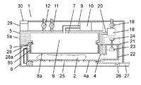
- 2 is a cross-sectional view taken along the line 2-2 of FIG. 1 of the washing machine according to the present embodiment.
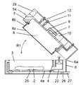
- FIG. 3 is a cross-sectional view of the washing machine in FIG. 2 with the lid body opened.
- 4 is a cross-sectional view taken along the line 4-4 of FIG. 1 of the washing machine according to the present embodiment.
- FIG. 5 is a cross-sectional view showing a state where the inside of the pressing portion in FIG. 4 is pressurized.
- 6 is a cross-sectional view taken along line 6-6 of FIG. 1 in another example of the washing machine of the present embodiment.
- 7 is a cross-sectional view taken along line 7-7 of FIG.
- FIG. 8 is a cross-sectional view taken along the line 8-8 in FIG. 1 in the washing machine according to the third embodiment of the present disclosure.
- FIG. 9 is a cross-sectional view of the washing machine in FIG. 8 with the lid open.
- FIG. 10 is a diagram showing the transition of the internal pressure of the pressing portion of the washing machine in the present embodiment.
- FIG. 11 is a diagram illustrating an example of the expansion / contraction specification change of the pressing portion in the washing process with respect to the volume of the washing object of the washing machine in the present embodiment.
- 12 is a cross-sectional view taken along the line 12-12 of FIG. 1 in the washing machine according to the fourth embodiment of the present disclosure.
- FIG. 13 is a cross-sectional view taken along line 13-13 of FIG. 1 of the washing machine according to the fifth embodiment of the present disclosure.
- FIG. 14 is a cross-sectional view of the washing machine in FIG. 13 with the lid open.
- FIG. 15 is a schematic diagram showing the operation of the washing machine in the present embodiment.
- FIG. 16 is a schematic diagram showing the operation of the washing machine in the present embodiment.
- FIG. 17 is a schematic diagram illustrating an operation of the washing machine according to the sixth embodiment of the present disclosure.
- FIG. 18 is a schematic diagram showing the operation of the washing machine in the present embodiment.
- FIG. 19 is a schematic diagram illustrating an operation of the washing machine according to the seventh embodiment of the present disclosure.
- FIG. 20 is a schematic diagram showing the operation of the washing machine in the present embodiment.
- FIG. 21 is a schematic diagram illustrating an operation of the washing machine according to the eighth embodiment of the present disclosure.
- FIG. 22 is a longitudinal sectional view showing a configuration of a conventional washing machine
- a washing machine includes a washing tub that accommodates an object to be washed and washing water, a pressurizing and depressurizing unit that has a pressing part that can move forward and backward with respect to the object to be washed inside the washing tub, and a pressure and depressurizing part
- a pressure control unit that pressurizes and depresses the object to be cleaned by the pressing unit so that the object to be cleaned contracts and expands, and a multi-directional water flow is generated inside the object to be cleaned. It is configured. With this configuration, multidirectional water flows can be generated inside the object to be cleaned without stirring the object to be cleaned. As a result, it is possible to enhance the cleaning effect while suppressing fabric damage and shape loss.
- the pressurizing and depressurizing unit presses the object to be cleaned by the pressing unit, thereby causing the cleaning water included in the object to be washed out to the outside of the object to be cleaned.
- the cleaning water is made to flow into the object to be cleaned so that the object to be cleaned contains cleaning water.
- the third disclosure further includes, in the first or second disclosure, a water storage unit that stores cleaning water that has flowed from the inside of the object to be cleaned to the outside of the object to be cleaned when pressed against the object to be cleaned,
- the water storage unit communicates with the inside of the cleaning tank and is disposed outside the cleaning tank.
- the fourth disclosure further includes a water storage unit that stores cleaning water that has flowed out from the inside of the object to be cleaned to the outside of the object to be cleaned when pressed against the object to be cleaned in the first or second disclosure,
- the water reservoir is configured inside the cleaning tank.
- the water storage section is configured such that the level of the stored cleaning water is higher than the object to be cleaned inside the cleaning tank.
- the cleaning water inside the water storage section can be forcibly returned toward the object to be cleaned inside the cleaning tank due to the head difference between the cleaning water inside the water storage section and the cleaning water inside the cleaning tank. it can.
- the flow rate of the cleaning water flowing into the object to be cleaned that is pressed and contracted can be accelerated, and the cleaning effect can be enhanced.
- a water storage pressurization unit is provided in the water storage unit, and the water storage pressurization unit is configured to release the pressing of the object to be cleaned by the pressing unit. It is comprised so that the washing water accommodated in the water storage part may be pressurized. With this configuration, the cleaning water inside the water storage unit can be forcibly returned toward the object to be cleaned inside the cleaning tank. Thereby, the flow rate of the cleaning water flowing into the object to be cleaned which is compressed and contracted can be accelerated, and the cleaning effect can be enhanced.
- the pressurizing / decompressing unit supplies the fluid to the inside of the pressing unit and expands the pressing unit by supplying fluid into the pressing unit.
- a pressurizing device and a discharge valve for discharging the fluid inside the pressing portion are provided.
- the control unit drives the pressurizing device to supply the fluid to the inside of the pressing unit
- the control unit closes the discharge valve, stops the pressurizing device, and presses it.
- the discharge valve is opened.
- the pressing unit is provided with a lid body that can be freely opened and closed at the upper part of the cleaning tank, and the control unit is configured such that the user cleans the lid body.
- the pressurizing / depressurizing unit is configured to control the pressure unit so as to release or pull the pressure when the tank is closed.
- control unit is configured to release the pressure of the pressing unit by opening the discharge valve and releasing the inside of the pressing unit to the atmosphere.
- the pressurizing device is configured by a device capable of pressurizing and depressurizing the inside of the pressing unit, and the control unit performs the depressurizing operation of the pressurizing device, thereby the pressing unit. It is comprised so that a pressure may be pulled. With this configuration, when the user closes the lid, a large force for contracting the pressing portion is not required, and the convenience for the user is not impaired.
- the twelfth disclosure further includes a pressure detection unit that measures an internal pressure of the pressing unit, and the control unit is configured to detect when the pressure is detected by the pressure detection unit or The expansion and contraction of the pressing part in the washing process is controlled according to the internal pressure value of the pressing part at the time of contraction.
- the control unit estimates the volume of the object to be cleaned based on various values calculated by the control unit from the internal pressure value of the pressing unit detected by the pressure detection unit, The expansion and contraction of the pressing part in the washing process is controlled according to the estimation result.
- the control unit estimates the volume of the object to be cleaned based on various values calculated by the control unit from the internal pressure value of the pressing unit detected by the pressure detection unit, The expansion and contraction of the pressing part in the washing process is controlled according to the estimation result.
- the control unit determines the maximum value ( ⁇ P / increase) of the increase value per unit time of the internal pressure of the pressing unit detected by the pressure detection unit.
- ( ⁇ T) max the pressurizing and depressurizing unit is controlled so as to change the expansion or contraction speed or displacement or maximum pressure of the pressing unit in the washing step.
- the control unit performs washing according to the maximum value Pmax within a predetermined time of the internal pressure of the pressing unit detected by the pressure detection unit.
- the pressurizing and depressurizing unit is controlled to change the speed or displacement or the maximum pressure or expansion pressure of the pressing unit in the process.
- the volume of the object to be cleaned is estimated by comparing the internal pressure of the pressing unit stored in the control unit in advance with the threshold value Pm of the maximum value Pmax within a predetermined time. Proper cleaning is achieved. As a result, it is possible to enhance the cleaning effect while suppressing fabric damage and deformation.
- control unit is configured to detect the internal pressure of the pressing unit by the pressure detection unit before supplying water to the cleaning tank. Yes.
- the pressurizing and depressurizing unit is connected to the driving unit, the rotating plate rotated by the driving unit, and the rotating plate and the shaft. And a pressing portion.
- the pressurizing and depressurizing unit is configured to contract and expand the object to be cleaned by pressing and releasing the pressure on the object to be cleaned by a plurality of pressing units, and to generate multidirectional water flows inside the object to be cleaned.
- a plurality of parts of the object to be cleaned are pressed at different timings such as alternately or sequentially inside the cleaning tank. Therefore, without stirring the object to be cleaned, a multi-directional water flow can be generated throughout the object to be cleaned, and the cleaning effect can be enhanced by suppressing fabric damage and shape loss.
- the washing machine of this indication can respond easily even if the part from which the thickness of a to-be-cleaned object differs exists in a washing tank by having a several press part.
- the 19th disclosure is the 18th disclosure, in particular, there are a plurality of pressurizing and depressurizing sections.
- the plurality of pressurizing and depressurizing units are a plurality of pressing portions that are freely expandable and contractible, a plurality of pressure pumps that supply fluid to the inside of the plurality of pressing portions, and a plurality of discharges that discharge the fluid inside the plurality of pressing portions. And a valve.
- the control unit is configured to control the plurality of pressure-reducing units such that each of the plurality of pressing units expands and contracts at an arbitrary timing. With this configuration, a plurality of parts of the object to be cleaned are pressed at different timings.
- the plurality of pressing portions include at least a first pressing portion and a second pressing portion.
- the pressurizing and depressurizing unit communicates via the plurality of pressing units, the plurality of discharge valves for discharging the fluid inside the plurality of pressing units, the switching unit including a plurality of on-off valves, and the plurality of pressing units and the switching unit.
- a pressurizing pump for supplying a fluid to the inside of the plurality of pressing portions.
- the control unit is configured to control the pressurizing and depressurizing unit so that the second pressing unit contracts when the first pressing unit expands. With this configuration, the pressurization to the plurality of pressing portions is selectively switched by one pressurizing pump, and the plurality of portions of the object to be cleaned are alternately pressed.
- the pressurizing and depressurizing unit includes a suction path that communicates the plurality of pressing units and the suction side of the pressurizing pump, and a suction path switching unit provided in the suction path. And a discharge path that communicates the plurality of pressing parts with the discharge side of the pressure pump, and a discharge path switching part provided in the discharge path.
- the control unit moves the pressurization / decompression unit through the suction path switching unit and the discharge path switching unit so that the air inside the first pressing unit contracting moves into the second pressing unit expanding. Configured to control. With this configuration, the plurality of pressing portions are efficiently expanded and contracted simultaneously, and the plurality of portions of the object to be cleaned are pressed at different timings.
- the pressurizing and depressurizing unit includes an electric motor, a rotating shaft that has a plurality of crank portions and is rotated by the electric motor, and a shaft that is rotatably connected to the crank portion. And a plurality of pressing portions connected via each other. With this configuration, the plurality of parts of the object to be cleaned are pressed at different timings at a speed corresponding to the rotation speed of the electric motor.
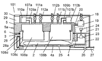
- FIG. 1 is an external perspective view of the washing machine according to the first embodiment of the present disclosure.
- 2 is a cross-sectional view taken along the line 2-2 of FIG. 1 of the washing machine according to the present embodiment.
- FIG. 3 is a cross-sectional view of the washing machine in FIG. 2 with the lid body opened.
- 4 is a cross-sectional view taken along the line 4-4 of FIG. 1 of the washing machine according to the present embodiment.
- FIG. 5 is a cross-sectional view showing a state where the inside of the pressing portion in FIG. 4 is pressurized. Note that the drawings shown in the embodiments of the present disclosure are all schematic, and the arrangement, size, and the like are described to the extent that they are sufficient for explanation.
- the washing machine 1 includes a lower water tank 6 and an upper lid 5.
- the water tank unit 6 includes a cleaning tank 4 formed in a square shape having a predetermined depth.
- An opening 3 is formed entirely on the upper surface of the cleaning tank 4.
- An object to be cleaned 2 that is a laundry such as clothes is fed from the opening 3.
- the lid 5 is pivotally attached to the rear edge of the upper side of the water tank section 6 by a hinge section 6 a and opens and closes the opening 3 of the cleaning tank 4.
- the object to be cleaned 2 is accommodated in the bottom 4a of the cleaning tank 4 by the user.
- the article to be cleaned 2 is, for example, a woolen fabric such as a sweater or a cardigan, a delicate scarf made of ultrafine fibers, and the like. That is, it is preferable that the object to be cleaned 2 loses its shape or becomes painful when it is washed with a general washing machine in which mechanical force acts on the object to be cleaned 2.
- a handle 5 a is provided on the front surface of the lid 5.
- the lid 5 is configured such that the user holds the handle 5a and rotates it in the direction of the arrow R1 shown in FIG. 3 to open and close the opening 3 and hold it in an open state.
- the lid 5 is locked by a lock device (not shown) and held in a closed state. Further, when opening, the lock device is unlocked by operating the handle 5a.
- a pressurizing and depressurizing unit 7 is provided inside the lid 5.
- the pressurizing / decompressing unit 7 communicates with the inside of the pressing unit 8 via a hose 9 and a flexible bag-shaped pressing unit 8 formed in a bellows shape with rubber or synthetic resin. It has a pressurizing pump 10 that supplies a fluid such as gas or liquid inside, and a discharge valve 11 that discharges the fluid supplied to the pressing unit 8 to the outside of the pressing unit 8.
- the pressing part 8 has a pressing surface 8a that presses the article to be cleaned 2 and a bellows-like stretchable part 8b.
- the pressing portion 8 is attached to the cleaning tank 4 side of the lid 5 and is provided so as to expand and contract by expanding and contracting, and is configured to be movable forward and backward with respect to the object to be cleaned 2 accommodated in the bottom portion 4 a of the cleaning tank 4. Has been.
- the pressing portion 8 expands to the extent that the pressing surface 8 a reaches the bottom portion 4 a of the cleaning tank 4.
- the pressurizing and depressurizing unit 7 is provided with a constant pressure release valve 12 that opens when the inside of the pressing unit 8 reaches a predetermined pressure and discharges the fluid to the outside.
- the constant pressure release valve 12 prevents the pressing portion 8 from being pressurized beyond a predetermined pressure.
- the fluid supplied to the inside of the pressing portion 8 will be described as air.
- the lid 5 is provided with a deformable hollow packing 16 (see FIGS. 4 and 5).
- the packing 16 comes into close contact with the seal portion 17 formed in a concave shape along the peripheral edge portion of the opening 3 of the cleaning tank 4.
- the inside of the washing tank 4 becomes a watertight and airtight space, and water and air are discharged from the opening 3 to the outside when the washing, rinsing, and dewatering steps are performed. There is no leakage.
- the lid 5 is provided with a water supply path 20 for supplying cleaning water to the cleaning tank 4.
- a water supply valve 18 is provided in the water supply path 20 and communicates with the inside of the cleaning tank 4 through a detergent case 19. By opening and closing the water supply valve 18, tap water (cleaning water) is supplied to the cleaning tank 4 and stopped.
- a water level detection unit 21 is provided so as to communicate with the inside of the cleaning tank 4.
- the water level detection part 21 detects when the water level detection tank 22 which has an opening part upwards, the float 23 which moves up and down according to the fluctuation
- a water level switch 24 is provided.
- a drain hole 25 for discharging the washing water used in the washing process or the like is formed in the bottom 4a of the washing tank 4.
- the drain hole 25 communicates with a drain path 27 provided with a drain valve 26. By opening and closing the drain valve 26, the cleaning water in the cleaning tank 4 is drained and stopped.
- the water tank section 6 is provided with an overflow channel 28 for draining the cleaning water inside the cleaning tank 4 to the outside when the water level inside the cleaning tank 4 becomes a predetermined level or more.
- the overflow path 28 has an overflow hole 28 a in the upper part of the washing tank 4 and communicates with the drain path 27 on the downstream side of the drain valve 26.
- the control unit 29 is disposed on the side surface inside the lid 5.
- An operation display unit 30 is provided on the upper surface of the control unit 29.
- the control unit 29 controls the pressurizing pump 10, the discharge valve 11, the water supply valve 18, the drain valve 26, and the like, and sequentially executes each step of washing, rinsing, and dehydration.
- the water storage unit 13 is provided adjacent to the cleaning tank 4.
- the water reservoir 13 is configured to communicate with the inside of the cleaning tank 4 and below the side surface. Although cleaning water is supplied to the cleaning tank 4, the cleaning water can move between the inside of the cleaning tank 4 and the inside of the water storage unit 13 through the communication unit 14.
- the upper surface 13a of the water reservoir 13 is configured to be higher than the pressing surface 8a.
- the level of the cleaning water stored in the water storage unit 13 is higher than at least the article 2 to be cleaned inside the cleaning tank 4.
- a vent hole 15 is provided in the upper surface 13a of the water storage section 13.
- the vent hole 15 exhausts the air inside the water storage unit 13 to the outside when the cleaning water flows into the water storage unit 13 from the communication unit 14, and allows external air to flow when the cleaning water flows out from the water storage unit 13. This is a through hole for supplying air.
- the user inputs the selection of the driving course, the time of each process, and the like from the operation display unit 30 provided on the upper front portion of the lid 5.
- the control unit 29 executes the processes from washing to dehydration as a series of operations based on the set content.
- the user can arbitrarily select such as performing only the washing step. Further, this setting operation may be performed after setting an object to be cleaned 2 described later.
- the user After the user operates the handle 5a to unlock, the user opens the lid 5 and sets the shape of the article 2 to be cleaned on the bottom 4a in the cleaning tank 4. Depending on the size of the object 2 to be cleaned, it may be set by folding.
- the control unit 29 controls the pressurizing and depressurizing unit 7 so as to release the pressure inside the pressing unit 8 or suck and pull the inside of the pressing unit 8. Specifically, the control unit 29 releases the pressure inside the pressing unit 8 by opening the discharge valve 11 and releasing the inside of the pressing unit 8 to the atmosphere. Or the control part 29 rotates the pressurization pump 10 in the reverse direction to the time of pressurization, drives as a decompression pump, and carries out suction
- control unit 29 starts the washing operation according to the operation course set by the operation display unit 30.
- the control unit 29 first performs a water supply operation.
- the control unit 29 opens the water supply valve 18, tap water and detergent are supplied as cleaning water from the water supply path 20 to the inside of the cleaning tank 4.
- the washing water gradually permeates the article to be cleaned 2 and enters a state of being included between the fibers of the article to be cleaned 2.
- the control unit 29 detects that the cleaning water is supplied to the predetermined water level as shown in FIG. 4 in the cleaning tank 4 and reaches the predetermined water level by the water level switch 24 of the water level detection unit 21, The valve 18 is closed.
- the control unit 29 drives the pressure pump 10 to supply air to the inside of the pressing unit 8 to expand the pressing unit 8.
- the expansion / contraction part 8 b extends and the pressing part 8 extends toward the object to be cleaned 2
- the pressing surface 8 a compresses the object to be cleaned 2.
- the object to be cleaned 2 is pressed and compressed by the pressing surface 8a, and the thickness is reduced.
- the cleaning water contained in the object to be cleaned 2 is pushed out of the object to be cleaned 2.
- a water flow is generated from the inside of the article to be cleaned 2 to the outside, and the dirt adhering to the object to be cleaned 2 is removed away from the fibers by the water flow.
- cleaned material 2 moves to the water storage part 13 in the arrow A direction through the communication part 14, as FIG. 5 shows.
- the air that has been inside the water reservoir 13 is discharged from the vent hole 15 to the outside.
- the control unit 29 drives the pressurizing pump 10 for a predetermined time or until the inside of the pressing unit 8 reaches a predetermined pressure. Thereafter, the control unit 29 immediately stops the pressurizing pump 10 and opens the discharge valve 11. By opening the discharge valve 11, the air inside the pressing portion 8 is discharged to the outside of the pressing portion 8, and the internal pressure of the pressing portion 8 decreases. Note that various well-known methods such as detection by a pressure gauge can be applied to detect that the inside of the pressing portion 8 reaches a predetermined pressure, and detailed description thereof will be omitted.
- the pressurization and decompression unit 7 causes the object to be cleaned 2 to contract and expand (for example, pressurization 1 second due to expansion of the pressing unit 8 and decompression 1 second due to contraction of the pressing unit 8) for a predetermined time (for example, 10 minutes)
- a predetermined time for example, 10 minutes
- the press-washing effect can be exerted on the object to be cleaned 2. That is, it is possible to remove dirt by generating water streams from multiple directions inside the object to be cleaned 2 without mechanical force such as stirring or tapping on the object to be cleaned 2.
- control unit 29 executes the rinse process and the dehydration process following the washing process.
- a rinsing operation is performed after a draining operation and a preliminary dehydrating operation.
- the draining operation the drain valve 26 is opened, and the cleaning water inside the cleaning tank 4 is drained to the outside through the drain path 27.
- the pressurizing pump 10 is driven with the drain valve 26 opened, the object to be cleaned 2 is pressed and compressed, and a part of the cleaning water contained in the object to be cleaned 2 is forced. Drained.
- the water supply valve 18 is opened, and a predetermined amount of cleaning water is supplied into the cleaning tank 4.
- the washing water supplied to the inside of the washing tank 4 does not contain a detergent.
- the pressure pump 10 is driven for a predetermined time, and pressure is applied to the article 2 to be cleaned by expansion of the pressing portion 8 and pressure reduction is performed by discharging air inside the pressing portion 8.
- the to-be-cleaned object 2 repeats shrinkage
- This rinsing process is repeated a plurality of times (for example, twice).
- the control unit 29 executes the dehydration process after executing the rinsing process.
- the drain valve 26 is opened, and the cleaning water inside the cleaning tank 4 is drained to the outside.
- the pressurizing pump 10 is driven with the drain valve 26 opened, the object to be cleaned 2 is pressed and compressed, and a part of the cleaning water contained in the object to be cleaned 2 is forcibly drained. Is done.
- the pressurizing / decompressing unit 7 discharges the fluid inside the pressing unit 8, the pressureable pump 10 that expands the pressing unit 8, the flexible pressing unit 8 having flexibility. It comprises a discharge valve 11. Then, the head pressure of the washing water stored in the water storage unit 13 is used to contract the pressing unit 8.
- the present invention is not limited to this.
- the pressure reduction for contracting the pressing portion 8 may be performed by a pressure reduction pump (not shown) instead of the discharge valve 11.
- the pressurization pump 10 may be reversed to be used as a decompression pump.
- the washing machine can obtain a stable cleaning performance in accordance with the state of the article to be cleaned 2 and the like.
- FIG. 6 is a cross-sectional view taken along the line 6-6 in FIG. 1 in another example of the washing machine of the present embodiment. That is, instead of the vent hole 15 of the water storage unit 13 in FIG. 4, a water storage pressurization unit 31 (for example, a pressurizing pump or a piston) that pressurizes the inside of the water storage unit 13 on the upper part of the water storage unit 13, and the water storage unit 13. And an exhaust valve 32 for stopping the exhaust is provided.
- a water storage pressurization unit 31 for example, a pressurizing pump or a piston
- the pressing surface 8a has an appropriate flexibility while having a rigidity capable of compressing the article 2 to be cleaned.
- the pressing surface 8a itself may be formed of a material such as rubber or resin.
- the pressing surface 8a may be configured, for example, by affixing a foamed rubber sheet having a predetermined thickness and no water absorption to a flat plate formed of a material having high rigidity. Etc. are not particularly limited. With this configuration, even if the height of the object 2 to be cleaned housed in the bottom portion 4a is different due to compression deformation, the pressing surface 8a can be deformed according to the height, and the pressing surface 8a is to be cleaned. 2 can be pressed across. Thereby, the washing machine can obtain a stable cleaning performance.
- flexibility it is not restricted to the press surface 8a, but the bottom part 4a of the washing tank 4 comprised so that the to-be-cleaned object 2 may be pinched opposes the press surface 8a may have moderate softness
- the pressing surface 8a may have a rigidity that does not deform even when a cloth or wool is compressed. With such a configuration, when the pressing portion 8 is expanded, the pressing surface 8a can be tilted according to the height of the compression deformation of the article to be cleaned 2 due to the difference in flexibility and extension of the stretchable portion 8b. Yes, the pressing surface 8 a can press the entire object to be cleaned 2. Thereby, the washing machine can obtain a stable cleaning performance.
- the pressing surface 8a may be formed in an uneven shape.
- the uneven shape is not particularly limited, such as a circular or polygonal protrusion or groove, regardless of the length. If consideration is given, it is desirable to form so as not to enclose the flow of cleaning water discharged from the object to be cleaned 2 when pressed.
- the washing machine includes the cleaning tank 4 that stores the object to be cleaned 2 and the cleaning water, and the pressing portion 8 that can freely move relative to the object to be cleaned 2 inside the cleaning tank 4.
- the pressurizing / depressurizing unit 7 and a control unit 29 for controlling the pressurizing / depressurizing unit 7 to perform washing, rinsing, and dehydration sequentially are provided.
- the object 2 to be cleaned is contracted and expanded by pressing and releasing the pressure, and a multi-directional water flow is generated inside the object 2 to be cleaned. With this configuration, multidirectional water flows can be generated inside the object to be cleaned 2 without stirring the object 2 to be cleaned. As a result, it is possible to enhance the cleaning effect by suppressing fabric damage and shape loss of the object to be cleaned 2.
- the pressurization / decompression unit 7 presses the object 2 to be cleaned with the pressing unit 8, thereby causing the cleaning water contained in the object 2 to flow out of the object 2 to be cleaned and the object to be cleaned by the pressing unit 8.
- the cleaning water that has flowed out of the object to be cleaned 2 is caused to flow into the object to be cleaned 2 by releasing the pressure on the object 2.
- the water storage part 13 which accommodates the wash water which flowed out of the to-be-cleaned object 2 from the inside of the to-be-cleaned object 2 at the time of the press to the to-be-cleaned object 2, It communicates and is arranged outside the washing tank 4. With this configuration, the object to be cleaned 2 can be spread and washed over a wide range inside the cleaning tank 4.
- the water storage unit 13 is configured such that the level of the stored cleaning water is higher than the object to be cleaned 2 inside the cleaning tank 4. With this configuration, the cleaning water inside the water storage unit 13 is forced toward the object to be cleaned 2 inside the cleaning tank 4 due to the head difference between the cleaning water inside the water storage unit 13 and the cleaning water inside the cleaning tank 4. Can be restored. Thereby, the flow rate of the cleaning water flowing into the object to be cleaned 2 compressed and contracted can be accelerated, and the cleaning effect can be enhanced.
- the water storage pressurization part 31 is provided in the water storage part 13, and when the press to the to-be-cleaned object 2 by the press part 8 is cancelled
- the cleaning water inside the water storage unit 13 can be forcibly returned toward the object to be cleaned 2 inside the cleaning tank 4. Thereby, the flow rate of the cleaning water flowing into the object to be cleaned 2 compressed and contracted can be accelerated, and the cleaning effect can be enhanced and the cleaning time can be shortened.
- the pressurizing / decompressing unit 7 includes a pressing unit 8 that can be expanded and contracted, a pressurizing pump 10 that expands the pressing unit 8 by supplying a fluid such as air into the pressing unit 8, and an internal unit of the pressing unit 8. And a discharge valve 11 for discharging the fluid.
- control unit 29 closes the discharge valve 11 when driving the pressurizing pump 10 to supply air to the inside of the pressing unit 8, stops the pressurizing pump 10, and draws air inside the pressing unit 8. When discharging, the discharge valve 11 is opened. With this configuration, it is possible to accurately press and release the object to be cleaned 2.
- control unit 29 is configured to control the pressurizing and depressurizing unit 7 so as to release or pull the pressure of the pressing unit 8 when the user closes the lid 5 with respect to the cleaning tank 4. With this configuration, the user can perform an operation of closing the lid 5 without requiring a force for contracting the pressing portion 8.
- control unit 29 is configured to release the pressure inside the pressing unit 8 by opening the discharge valve 11 and releasing the inside of the pressing unit 8 to the atmosphere. With this configuration, the user can perform an operation of closing the lid 5 without requiring a force for contracting the pressing portion 8.
- control unit 29 may be configured to rotate the pressurizing pump 10 in a direction opposite to that during pressurization and drive as a decompression pump to perform a decompression operation, thereby pulling the inside of the pressing unit 8.
- the user can perform an operation of closing the lid 5 without requiring a force for contracting the pressing portion 8.
- the press part 8 is comprised by one, it is not restricted to this, The some press part 8 may be comprised inside the washing tank 4.
- the pressing surface 8 a may be provided independently on the lower surface of each pressing portion 8.
- one pressing plate (not shown) is provided so as to connect the lower surfaces of the plurality of pressing portions 8, and this pressing plate is configured to act as a pressing surface 8 a on the object to be cleaned 2. Also good.
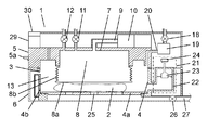
- (Embodiment 2) 7 is a cross-sectional view taken along line 7-7 of FIG. 1 in the washing machine according to the second embodiment of the present disclosure.
- the washing machine according to the present embodiment is characterized in that the water storage unit 13 is configured inside the washing tub 4.
- Other configurations are the same as those of the first embodiment, the same reference numerals are given to the same configurations, and the detailed description of the first embodiment is used.
- the water storage unit 13 that stores the cleaning water that flows out from the inside of the article to be cleaned 2 when pressed against the object to be cleaned 2 is provided inside the cleaning tank 4.
- the water storage section 13 is formed in a space between the side wall 4b of the cleaning tank 4 and the expansion / contraction section 8b that is the side wall of the pressing section 8 that can freely expand and contract.
- the cleaning water that has flowed out of the object to be cleaned 2 from the inside of the object to be cleaned 2 pressurized by the expansion of the pressing unit 8 moves to the water storage unit 13 and is stored therein.
- the volume of the space serving as the water storage unit 13 is a portion excluding the volume of the pressing unit 8 that expands and contracts vertically in the cleaning tank 4.
- the inside of the cleaning tank 4 is occupied by a large area by the pressing part 8, and the volume and horizontal cross-sectional area of the water storage part 13 are smaller than the volume and horizontal cross-sectional area of the cleaning tank 4.
- the surface of the wash water stored in the water storage unit 13 is increased, and the water head pressure is increased.
- the pressing part 8 contracts, the washing water vigorously flows into the object to be cleaned 2 to expand the object to be cleaned 2 and further contract the pressing part 8.
- a water flow in a direction different from the water flow generated when the object to be cleaned 2 is pressed is generated inside the object to be cleaned 2, and the dirt is further removed.
- the water storage unit 13 that stores the washing water that flows out from the inside of the article to be washed 2 to the outside of the article to be washed 2 when pressed against the article to be washed 2 4 is further arranged inside.
- the configuration it is possible to secure a space for storing the cleaning water flowing out from the inside of the article to be cleaned 2 to the inside of the cleaning tank 4, and the configuration can be simplified.
- the volume and horizontal cross-sectional area of the water storage part 13 are formed small, the water head pressure increases and the inflow rate of the washing water increases. Thereby, the cleaning effect can be enhanced.
- FIG. 3 is a cross-sectional view taken along the line 8-8 in FIG. 1 in the washing machine according to the third embodiment of the present disclosure.
- FIG. 9 is a cross-sectional view of the washing machine in FIG. 8 with the lid open.
- FIG. 10 is a diagram showing the transition of the internal pressure of the pressing portion of the washing machine in the present embodiment.
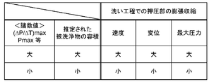
- FIG. 11 is a diagram illustrating an example of the expansion / contraction specification change of the pressing portion in the washing process with respect to the volume of the washing object of the washing machine in the present embodiment.
- the washing machine of the present embodiment is characterized in that, in addition to the configuration of the first or second embodiment, a pressure detection unit 33 that measures the internal pressure of the pressing unit 8 is provided.
- a pressure detection unit 33 that measures the internal pressure of the pressing unit 8 is provided.
- Other configurations are the same as those in the first embodiment or the second embodiment, the same reference numerals are given to the same configurations, and the detailed description of the first embodiment is used.
- a pressure detection unit 33 is provided in a discharge path provided with a discharge valve 11 that discharges the fluid inside the pressing unit 8 to the outside of the pressing unit 8.
- the pressure detection unit 33 measures the internal pressure of the pressing unit 8.
- a general pressure gauge such as a liquid column type, a Bourdon tube type, or a diaphragm type is used.
- the pressure detector 33 is provided in the vicinity of the discharge valve 11 so that it can measure the depressurization state at the time of fluid discharge with high sensitivity. Further, by providing the discharge path so as to be separable from the pressurizing and depressurizing unit 7 including the pressing unit 8, the pressure detection unit 33 can be easily inspected and replaced.
- the control unit 29 includes a storage unit (not shown) configured by a nonvolatile memory or the like.
- reference data to be compared with the internal pressure of the pressing unit 8 such as the threshold value Ps of the maximum value ( ⁇ P / ⁇ T) max within a predetermined time of the pressure increase speed, the threshold value Pm of the pressure maximum value Pmax within the predetermined time,
- the drive specification data (expansion and contraction speed, displacement, maximum pressure, etc.) of the pressurizing pump 10 associated with these threshold values are stored in advance.
- control unit 29 starts the washing operation according to the operation course set in the operation display unit 30.
- the control unit 29 drives the pressurizing pump 10 of the pressurizing and depressurizing unit 7 and supplies air to the inside of the pressing unit 8 to expand the pressing unit 8 prior to the water supply operation to the cleaning tank 4. At that time, the control unit 29 uses the pressure detection unit 33 to detect the increase in the internal pressure of the pressing unit 8 over time.
- the state of the detected increase in the internal pressure of the pressing portion 8 varies depending on the volume of the object to be cleaned 2 set in the cleaning tank 4.
- the volume of the object to be cleaned 2 can also be expressed by the term “bath ratio” used by those skilled in the art.
- FIG. 10 is a diagram showing an example of a transition state of the internal pressure increase of the pressing portion 8 at this time.
- FIG. 10 is a graph comparing the detection data of one thick garment as a typical example of a large volume (small bath ratio) and one thin garment as a typical example of a small volume (large bath ratio). It is a thing.
- the maximum value ( ⁇ P / ⁇ T) max within a predetermined time of the increase value per unit time of the internal pressure of the pressing unit 8 is larger than the threshold value Ps, and the pressing unit 8
- the maximum value Pmax of the internal pressure within a predetermined time is also larger than the threshold value Pm.
- the maximum value ( ⁇ P / ⁇ T) max of the increase value per unit time of the internal pressure of the pressing unit 8 within a predetermined time is smaller than the threshold value Ps, and the internal pressure of the pressing unit 8 within the predetermined time.
- the maximum value Pmax is also smaller than the threshold value Pm.
- the volume of the object to be cleaned 2 is estimated by the control unit 29 as follows.
- the control unit 29 calculates various values such as an increase value ⁇ P / ⁇ T per unit time of the internal pressure of the pressing unit 8 from the internal pressure value of the pressing unit 8 detected by the pressure detection unit 33 every moment. And based on those calculated values, the maximum value ( ⁇ P / ⁇ T) max of the increase value per unit time of the internal pressure of the pressing portion 8 within a predetermined time, and the maximum value of the internal pressure of the pressing portion 8 within the predetermined time Various numerical values such as Pmax are calculated.
- the control unit 29 compares the maximum value ( ⁇ P / ⁇ T) max within a predetermined time of the rising speed detected by the pressure detection unit 33 with the threshold value Ps stored in advance in the storage unit, or the pressing unit 8
- the volume of the object to be cleaned 2 is estimated by comparing the maximum value Pmax of the internal pressure within a predetermined time with the threshold value Pm stored in advance in the storage unit.
- the control part 29 controls the drive of the pressurization pump 10 of the pressurization pressure reduction part 7 according to this estimation result, and changes expansion / contraction of the press part 8. And execute the washing process.
- the control unit 29 increases the expansion / contraction speed of the pressing unit 8 or increases the vertical displacement of the pressing surface 8a. Alternatively, the maximum pressure inside the pressing portion 8 is increased.
- the volume of the object 2 to be cleaned is small, for example, the expansion / contraction speed of the pressing portion 8 is decreased, the vertical displacement of the pressing surface 8a is decreased, or the maximum pressure inside the pressing portion 8 is increased. Make it smaller.
- the basic operation of the washing process, the subsequent rinsing process, and the dehydrating process are performed in the same manner as in the first embodiment.
- threshold values Ps and threshold values Pm may be provided, and the volume of the object to be cleaned 2 may be divided into a plurality of ranks to correspond.
- the determination of the volume of the object to be cleaned 2 by detecting the internal pressure of the pressing portion 8 may be performed after the water supply to the inside of the cleaning tank 4, the influence on the detection result due to moisture absorption of the object to be cleaned 2. In order to avoid this, it is preferable to carry out prior to the water supply operation to the cleaning tank 4 as in the present embodiment.
- the washing machine of the present embodiment further includes the pressure detection unit 33 that measures the internal pressure of the pressing unit 8 in addition to the configuration of the first embodiment or the second embodiment, and includes the control unit 29. Is configured to control the expansion and contraction of the pressing portion 8 in the washing process according to the internal pressure value of the pressing portion 8 at the time of expansion or contraction detected by the pressure detection unit 33. With this configuration, the expansion and contraction operation of the pressing portion 8 suitable for the volume of the article to be cleaned 2 can be performed.
- control part 29 estimates the volume of the to-be-cleaned object 2 from the internal pressure value of the press part 8 detected by the pressure detection part 33 with the various numerical values which the control part 29 calculates, and the washing process according to the estimation result It is comprised so that the expansion / contraction of the press part 8 may be controlled.
- the control part 29 estimates the volume of the to-be-cleaned object 2 from the internal pressure value of the press part 8 detected by the pressure detection part 33 with the various numerical values which the control part 29 calculates, and the washing process according to the estimation result It is comprised so that the expansion / contraction of the press part 8 may be controlled.
- control unit 29 presses the pressure in the washing process according to the maximum value ( ⁇ P / ⁇ T) max within a predetermined time of the increase value per unit time of the internal pressure of the pressing unit 8 detected by the pressure detection unit 33.
- the pressurizing and depressurizing unit 7 is controlled to change the expansion or contraction speed or displacement or the maximum pressure of the unit 8.
- the volume of the object 2 to be cleaned is compared with the threshold value Ps of the maximum value ( ⁇ P / ⁇ T) max within a predetermined time of the increase value per unit time of the internal pressure of the pressing unit 8 stored in advance in the storage unit.
- control unit 29 determines the speed or displacement or maximum pressure of the expansion / contraction of the pressing unit 8 in the washing process according to the maximum value Pmax of the internal pressure of the pressing unit 8 detected by the pressure detection unit 33 within a predetermined time.
- the pressurization / decompression unit 7 is controlled to change the pressure.
- the volume of the object to be cleaned 2 is estimated by comparing the internal pressure of the pressing unit 8 stored in advance in the storage unit with the threshold value Pm of the maximum value Pmax within a predetermined time. Appropriate washing is realized according to the situation. As a result, it is possible to enhance the cleaning effect while suppressing fabric damage and shape loss.
- the control unit 29 is configured to detect the internal pressure of the pressing unit 8 by the pressure detection unit 33 before supplying water to the cleaning tank 4. With this configuration, accurate estimation of the volume of the object to be cleaned 2 can be realized without being affected by moisture absorption of the object to be cleaned 2.
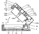
- (Embodiment 4) 12 is a cross-sectional view taken along the line 12-12 of FIG. 1 in the washing machine according to the fourth embodiment of the present disclosure.
- the pressurization / decompression unit 41 includes an electric motor 42 serving as a drive unit, a rotating plate 43 rotated by the electric motor 42, and a shaft 44, and a link mechanism thereof. It is comprised by the press part 45 connected with the link mechanism.
- Other configurations are the same as those of the first embodiment, the same reference numerals are given to the same configurations, and the detailed description of the first embodiment is used.
- one end of the shaft 44 is connected to the peripheral portion of the rotating plate 43 that is rotated by driving of the electric motor 42, and the pressing portion 45 is connected to the other end of the shaft 44.
- the pressing portion 45 is configured to be movable up and down by, for example, the peripheral portion being guided by the side wall of the cleaning tank 4.
- the rotating plate 43 rotates in the direction of the arrow R2 by driving the electric motor 42
- the pressing portion 45 moves up and down in the cleaning tank 4.
- the pressing part 45 descends inside the cleaning tank 4
- the object to be cleaned 2 is pressed and compressed, and the cleaning water inside the object to be cleaned 2 is pushed out and moved to the water storage part 13.
- the pressing portion 45 rises inside the cleaning tank 4 and moves away from the object to be cleaned 2, so that the object to be cleaned 2 is released from compression and expands, and the cleaning water stored in the water storage unit 13 enters the inside of the cleaning tank 4. Moving. When the pressing portion 45 moves back and forth in the vertical direction with respect to the object to be cleaned 2, the cleaning water moves in the direction of arrow C between the cleaning tank 4 and the water storage portion 13.
- the up and down strokes of the ascending position and the descending position of the pressing portion 45 can be set by the distance from the rotation center of the rotating plate 43 to the connecting position of the rotating plate 43 and the shaft 44.
- the water reservoir 13 may be provided either inside or outside the cleaning tank 4.
- the pressure reducing unit 41 includes the electric motor 42 that is the driving unit, the link mechanism that includes the rotating plate 43 and the shaft 44, and the pressing unit 45. I have. With this configuration, the outflow of cleaning water from the inside of the object to be cleaned 2 and the inflow of cleaning water into the inside of the object to be cleaned 2 are repeated, and the multidirectional water flow generated inside the object to be cleaned 2 is The dirt of the cleaning object 2 is removed. Thereby, the cleaning effect can be enhanced.
- the washing machine of the fifth embodiment is different from the washing machine of the first embodiment in the points described below, and has substantially the same configuration as the washing machine of the first embodiment in other points.
- the same reference numerals are given to the components common to the washing machine of the first embodiment, and a part or all of the description of the configuration will be omitted.
- FIG. 13 is a cross-sectional view taken along line 13-13 of FIG. 1 of the washing machine 101 in the present embodiment.
- FIG. 14 is a cross-sectional view of the washing machine 101 in FIG. 13 with the lid opened.
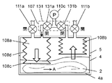
- 15 and 16 are schematic diagrams showing the operation of the washing machine 101 in the present embodiment.
- the pressurization / decompression unit 107 is composed of a first pressurization / decompression unit 107a and a second pressurization / decompression unit 107b.
- the first pressurizing / decompressing unit 107a includes a pressing unit 108a, a pressurizing pump 110a, and a discharge valve 111a.
- the second pressurizing / decompressing unit 107b includes a pressing unit 108b, a pressurizing pump 110b, and a discharge valve 111b.
- the pressurizing / decompressing unit 107 (107a, 107b) includes a flexible bag-shaped pressing unit 108 (108a, 108b) formed in a bellows shape with rubber or synthetic resin, and the pressing unit 108.
- a pressure pump 110 (110a, 110b) that communicates with the (108a, 108b) via the hose 109 (109a, 109b) and supplies a fluid such as gas or liquid to the inside of the pressing portion 108 (108a, 108b); It is comprised with the discharge valve 111 (111a, 111b) which discharges the fluid supplied to the press part 108 (108a, 108b) (henceforth, there is no need for distinction about the code
- the two pressure reducing parts 107 a and 107 b are provided side by side inside the lid 5.
- the pressing portions 108 a and 108 b are attached to the cleaning tank 4 side of the lid 5, are provided so as to expand and contract by expanding and contracting, and move forward and backward with respect to the object to be cleaned 2 accommodated in the bottom 4 a of the cleaning tank 4. It is configured freely.
- the pressing portions 108a and 108b respectively have a pressing surface 108c that presses the article to be cleaned 2 and a bellows-like expansion / contraction portion 108d. Further, the pressing portions 108 a and 108 b extend to the extent that the pressing surface 108 c reaches the bottom portion 4 a of the cleaning tank 4.
- the pressurizing and depressurizing unit 107 (107a, 107b) is provided with a constant pressure release valve 112 (112a, 112b) that opens when the inside of the pressing unit 108 (108a, 108b) reaches a predetermined pressure and discharges the fluid to the outside. ing.
- the constant pressure release valve 112 prevents the pressing unit 108 from being pressurized beyond a predetermined pressure.
- the fluid supplied to the inside of the pressing unit 108 will be described as air.
- the control unit 29 When the water supply is completed in the first washing process, the control unit 29 first closes the discharge valve 111a of the first pressurizing / decompressing unit 107a and keeps the pressurizing pump 110a for a predetermined time or the pressing unit 108a reaches a predetermined pressure. Drive until Thereby, air is supplied into the pressing portion 108a to expand the pressing portion 108a. As shown in FIG. 15, when the expansion / contraction part 108d extends and the pressing part 108a extends toward the object 2 to be cleaned, the object 2 to be cleaned below the pressing part 108a is compressed at the part pressed by the pressing surface 108c. And the thickness is reduced. At this time, the control unit 29 opens the discharge valve 111b of the second pressurizing / decompressing unit 107b to allow the pressing unit 108b to contract.
- the cleaning water contained in the object to be cleaned 2 is pushed out from the object to be cleaned 2.
- a water flow is generated inside the object to be cleaned 2, and the dirt adhering to the object to be cleaned 2 is removed away from the fibers by the water flow.
- the cleaning water contained in the object to be cleaned 2 moves in the direction indicated by the arrow A from the lower part of the pressing part 108a to the lower part of the pressing part 108b in the object 2 to be cleaned.
- the cleaning water moving in this way pushes the pressing surface 108c of the pressing portion 108b upward while expanding the article 2 to be cleaned below the pressing portion 108b, and discharges air from the open discharge valve 111b.
- the pressing part 108b is contracted.
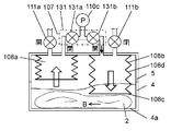
- the control unit 29 closes the discharge valve 111b of the second pressurizing and depressurizing unit 107b and drives the pressurizing pump 110b for a predetermined time or until the pressing unit 108b reaches a predetermined pressure. Air is supplied to the pressure part 108b to expand it. As shown in FIG. 16, when the expansion / contraction part 108d extends and the pressing part 108b extends toward the object to be cleaned 2, the pressing surface 108c presses the object 2 to be cleaned below the pressing part 108b. At this time, the control unit 29 opens the discharge valve 111a of the first pressurizing and depressurizing unit 107a to allow the pressing unit 108a to contract.
- the cleaning water contained in the object to be cleaned 2 is pushed out of the object to be cleaned 2 as the object to be cleaned 2 is compressed and its volume is changed by the expansion of the pressing part 108b. As a result, a water flow is generated inside the object to be cleaned 2, and the dirt adhering to the object to be cleaned 2 is removed away from the fibers by the water flow.
- the cleaning water contained in the object to be cleaned 2 moves in the direction indicated by the arrow B from the lower part of the pressing part 108b to the lower part of the pressing part 108a inside the object 2 to be cleaned. Then, the cleaning water moving in this way pushes the pressing surface 108c of the pressing portion 108a upward while expanding the article 2 to be cleaned below the pressing portion 108a, and discharges air from the open discharge valve 111a.
- the pressing part 108a is contracted.
- the pressing portions 108a and 108b are expanded and contracted at different timings when the pressing portions 108a and 108b are alternately (for example, pressurization 1 second by the expansion of the pressing portion 108a, and the pressing portion 108b.
- the depressurization due to contraction (1 second) is repeated for a predetermined time (for example, 10 minutes).
- a predetermined time for example, 10 minutes.
- control unit 29 executes the rinse process and the dehydration process following the washing process.
- a rinsing operation is performed after a draining operation and a preliminary dehydrating operation.
- the draining operation the drain valve 26 is opened, and the cleaning water inside the cleaning tank 4 is drained to the outside through the drain path 27.
- the discharge valves 111a and 111b are closed and the pressure pumps 110a and 110b are driven while the drain valve 26 is open, and the object to be cleaned 2 is pressed and compressed, and the object to be cleaned 2 A part of the cleaning water contained in is forcibly drained.
- the water supply valve 18 is opened, and a predetermined amount of cleaning water is supplied into the cleaning tank 4. Thereafter, similarly to the washing step, the pressure pumps 110a and 110b are driven, and the expansion and contraction of the pressing portions 108a and 108b are repeated at different timings to dilute the detergent concentration of the washing water inside the article to be cleaned 2. .
- This rinsing process is repeated a plurality of times (for example, twice).
- the control unit 29 executes the dehydration process after executing the rinsing process.
- the drain valve 26 is opened and the cleaning water inside the cleaning tank 4 is drained to the outside. Thereafter, with the drain valve 26 opened, the discharge valves 111a and 111b are closed, the pressure pumps 110a and 110b are driven, and the pressing portions 108a and 108b are expanded to press the object 2 to be cleaned. Compressed. Then, a part of the cleaning water contained in the object to be cleaned 2 is forcibly drained.
- the pressurizing / decompressing unit 107 includes a flexible pressing unit 108, a pressurizing pump 110 that supplies fluid to the inside of the pressing unit 108 and expands it, and an inside of the pressing unit 108.
- the exhaust valve 111 is configured to discharge and contract the fluid.
- pressure reduction for contracting the pressing portion 108 may be performed by a pressure reduction pump (not shown) instead of the discharge valve 111.
- the pressurization pump 110 may be reversed and used as a decompression pump.
- two pressurizing and depressurizing units 107 are provided, and are configured to alternately expand and contract.
- the present invention is not limited to this, and the pressing unit 108 may be sequentially expanded and contracted by providing three or more pressurizing / decompressing units 107 and operating them at different timings. In this case, when the at least one pressing portion 108 expands, the other pressing portions 108 are configured to contract, and the order of expansion and contraction may be either regular or random.
- the washing machine has a plurality of pressing portions 108.
- the pressurizing and depressurizing unit 107 is configured so that the object to be cleaned 2 contracts and expands by being pressed and released from the object to be cleaned 2 by a plurality of pressing units 108, and multidirectional water flows are generated inside the object to be cleaned 2.
- a plurality of parts of the object to be cleaned 2 are pressed at different timings such as alternately or sequentially inside the cleaning tank 4. Therefore, without stirring the article to be cleaned 2, a multi-directional water flow can be generated inside the article to be cleaned 2 to suppress cloth damage and shape loss, thereby enhancing the cleaning effect.
- the washing machine 101 includes a plurality of pressing portions 108, and therefore can easily cope with a portion where the thickness of the article to be cleaned 2 is different inside the cleaning tank 4.
- the plurality of pressurizing and depressurizing units 107 include a plurality of pressing units 108 that can be expanded and contracted, a plurality of pressurizing pumps 110 that supply fluid to the inside of the plurality of pressing units 108, and a fluid inside the plurality of pressing units 108. And a plurality of discharge valves 111 for discharging.
- the control unit 29 is configured to control the plurality of pressure-reducing units 107 so that each of the plurality of pressing units 108 expands and contracts at an arbitrary timing. With this configuration, the plurality of portions of the article to be cleaned 2 are pressed at different timings. Therefore, without stirring the article to be cleaned 2, a multi-directional water flow can be generated inside the article to be cleaned 2 to suppress cloth damage and shape loss, thereby enhancing the cleaning effect.
- FIG. 6 are schematic diagrams illustrating the operation of the washing machine according to the sixth embodiment of the present disclosure.
- the feature of the present embodiment is that the pressurizing and depressurizing unit 107 is connected to the discharge valve 111 (111a, 111b), the pressing unit 108 (108a, 108b), the pressing unit 108 (108a, 108b), and the switching unit 131.
- a pressurizing pump 110c communicating with each other.
- the control unit 29 is configured to control the pressurizing and depressurizing unit 107 by switching the switching unit 131 so that the other pressing unit 108b contracts when the one pressing unit 108a expands.
- Other configurations are the same as those of the fifth embodiment, the same reference numerals are given to the same configurations, and the detailed description uses those of the fifth embodiment.
- a plurality of flexible (e.g., two) pressing portions 108 (108 a and 108 b) having flexibility and provided on the cleaning tank 4 side of the lid 5 are the bottoms of the cleaning tank 4. It is configured to be movable forward and backward with respect to the object to be cleaned 2 accommodated in 4a.
- the pressurization / decompression unit 107 is provided with a discharge valve 111a for exhausting the air inside the one pressing unit 108a to the outside and a discharge valve 111b for exhausting the air inside the other pressing unit 108b to the outside. It has been.
- the pressurizing pump 110c communicates with the pressing part 108a and the pressing part 108b via the switching part 131.
- the switching unit 131 includes an on-off valve 131a that opens and closes communication with the pressing unit 108a, and an on-off valve 131b that opens and closes communication with the pressing unit 108b.
- the control unit 29 In the washing process, after a predetermined amount of water is supplied to the washing tank 4, the control unit 29 first closes the discharge valve 111a, opens the on-off valve 131a, closes the on-off valve 131b, and drives the pressure pump 110c. Thereby, air is supplied into the pressing portion 108a to expand the pressing portion 108a. As shown in FIG. 17, in the pressing portion 108 a, the stretchable portion 108 d extends, and the pressing surface 108 c presses the object to be cleaned 2. At this time, the control unit 29 opens the discharge valve 111b and enables the pressing unit 108b to contract.
- the cleaning water contained in the object to be cleaned 2 is pushed out of the object to be cleaned 2 as the object to be cleaned 2 is compressed and its volume is changed by the expansion of the pressing portion 108a. As a result, a water flow is generated inside the object to be cleaned 2, and the dirt adhering to the object to be cleaned 2 is removed away from the fibers by the water flow.
- the cleaning water contained in the object to be cleaned 2 moves in the direction indicated by the arrow A from the lower part of the pressing part 108a to the lower part of the pressing part 108b in the object 2 to be cleaned.
- the cleaning water moving in this way pushes the pressing surface 108c of the pressing portion 108b upward while expanding the article 2 to be cleaned below the pressing portion 108b, and discharges air from the open discharge valve 111b.
- the pressing part 108b is contracted.
- the control unit 29 closes the discharge valve 111b, opens the on-off valve 131b, closes the on-off valve 131a, drives the pressure pump 110c, supplies air into the pressing unit 108b, and expands the pressing unit 108b. .
- the expansion / contraction part 108 d extends, and the pressing surface 108 c presses the article 2 to be cleaned.
- the control unit 29 opens the discharge valve 111a and allows the pressing unit 108a to contract.
- the cleaning water contained in the object to be cleaned 2 is pushed out of the object to be cleaned 2 as the object to be cleaned 2 is compressed and its volume is changed by the expansion of the pressing part 108b. As a result, a water flow is generated inside the object to be cleaned 2, and the dirt adhering to the object to be cleaned 2 is removed away from the fibers by the water flow.
- the cleaning water contained in the object to be cleaned 2 moves in the direction indicated by the arrow B from the lower part of the pressing part 108b to the lower part of the pressing part 108a inside the object 2 to be cleaned. Then, the cleaning water moving in this way pushes the pressing surface 108c of the pressing portion 108a upward while expanding the article 2 to be cleaned below the pressing portion 108a, and discharges air from the open discharge valve 111a.
- the pressing part 108a is contracted.
- the pressing units 108 are alternately switched by one pressurizing pump 110c. It can be expanded and contracted, and a multi-directional water flow can be generated inside the object to be cleaned 2.
- two pressing portions 108 are provided, and are configured to alternately expand and contract.
- the present invention is not limited to this, and three or more pressing portions 108 may be provided, and the pressing portions 108 may be sequentially expanded and contracted by operating at different timings. In this case, when the at least one pressing portion 108 expands, the other pressing portions 108 are configured to contract, and the order of expansion and contraction may be either regular or random.
- the plurality of pressing portions 108 include at least the first pressing portion 108a and the second pressing portion 108b.
- the pressurizing and depressurizing unit 107 includes a plurality of pressing units 108, a plurality of discharge valves 111 that discharge the fluid inside the plurality of pressing units 108, a switching unit 131 that includes a plurality of on-off valves 131a and 131b, and a plurality of pressing units.
- a pressurizing pump 110c that communicates via the part 108 and the switching part 131 and supplies fluid to the inside of the plurality of pressing parts 108.
- the control unit 29 is configured to control the pressurization / decompression unit 107 so that the second pressing unit 108b contracts when the first pressing unit 108a expands. With this configuration, pressurization to the plurality of pressing portions 108 is selectively switched by one pressurizing pump 110c, and a plurality of portions of the object to be cleaned are alternately pressed.
- FIGS. 7 and 20 are schematic diagrams illustrating the operation of the washing machine according to the seventh embodiment of the present disclosure.
- a feature of the present embodiment is that the pressurizing and depressurizing unit 107 includes a plurality of pressing units 108 (108a and 108b).
- a suction path 132 communicating with the pressing portion 108 (108a, 108b) is formed on the suction side of the pressure pump 110c.
- Two on-off valves 133 a and 133 b are provided as the suction path switching unit 133.
- a discharge path 134 communicating with the pressing portion 108 (108a, 108b) is provided on the discharge side of the pressure pump 110c.
- a plurality of flexible (e.g., two) pressing portions 108 (108 a, 108 b) having flexibility and provided on the cleaning tank 4 side of the lid 5 are the bottoms of the cleaning tank 4. It is configured to be movable forward and backward with respect to the object to be cleaned 2 accommodated in 4a, and is provided with two communication paths, that is, a suction path 132 and a discharge path 134 for individually communicating the two pressing portions 108.
- the suction side of the pressurizing pump 110c is connected to a suction path 132 that communicates with the pressing portions 108a and 108b.
- a suction path switching unit 133 is provided in the suction path 132.
- an on-off valve 133a is provided in the suction path 132 between the pressing portion 108a and the pressurizing pump 110c.
- An opening / closing valve 133b is provided in the suction path 132 between the pressing portion 108b and the pressure pump 110c.
- the discharge side of the pressurizing pump 110c is connected to a discharge path 134 that communicates with the pressing portions 108a and 108b.
- a discharge path switching unit 135 is provided in the discharge path 134.
- an open / close valve 135a is provided in the discharge path 134 between the pressing portion 108a and the pressurizing pump 110c.
- An opening / closing valve 135b is provided in the discharge path 134 between the pressing portion 108b and the pressure pump 110c.
- the control unit 29 first closes the on-off valve 133a provided in the suction path 132 and opens the on-off valve 133b after a predetermined amount of water is supplied to the washing tank 4.
- the on-off valve 135b provided in the discharge passage 134 is closed, the on-off valve 135a is opened, and the pressurizing pump 110c is driven.
- the contraction of the pressing portion 108b and the pressing portion The expansion of 108a is performed simultaneously.
- the cleaning water contained in the object to be cleaned 2 is pushed out from the object to be cleaned 2.
- a water flow is generated inside the object to be cleaned 2, and the dirt adhering to the object to be cleaned 2 is removed away from the fibers by the water flow.
- the cleaning water contained in the object to be cleaned 2 moves in the direction indicated by the arrow A from the lower part of the pressing part 108a to the lower part of the pressing part 108b in the object 2 to be cleaned.
- the control unit 29 opens the on-off valve 133a provided on the suction path 132 and closes the on-off valve 133b.
- the on-off valve 135a provided in the discharge passage 134 is closed, the on-off valve 135b is opened, and the pressurizing pump 110c is driven.
- the contraction of the pressing portion 108a and the pressing portion The expansion of 108b is performed at the same time.
- the expansion / contraction portion 108d extends, and the pressing surface 108c presses the article 2 to be cleaned.
- the cleaning water contained in the object to be cleaned 2 is pushed out of the object to be cleaned 2 as the object to be cleaned 2 is compressed and its volume is changed by the expansion of the pressing part 108b. As a result, a water flow is generated inside the object to be cleaned 2, and the dirt adhering to the object to be cleaned 2 is removed away from the fibers by the water flow. Further, the cleaning water contained in the object to be cleaned 2 moves in the direction indicated by the arrow B from the lower part of the pressing part 108b to the lower part of the pressing part 108a in the object 2 to be cleaned. In this way, the washing process is executed by alternately repeating these operations.
- the opposite operations of expansion and contraction of the pressing portion 108a and the pressing portion 108b can be simultaneously performed by one pressure pump 110c, and different portions of the object to be cleaned 2 are alternately pressed by the plurality of pressing portions 108a and 108b. Therefore, a multi-directional water flow can be efficiently generated inside the article to be cleaned 2 and the cleaning effect can be enhanced.
- the pressure reducing unit 107 communicates the plurality of pressing units 108 and the suction side of the pressure pump 110 with each other. 132, a suction path switching unit 133 provided in the suction path 132, a discharge path 134 communicating the discharge sides of the plurality of pressing units 108 and the pressure pump 110, and a discharge path switching unit 135 provided in the discharge path 134. And further.
- the control unit 29 moves through the suction path switching unit 133 and the discharge path switching unit 135 so that the air inside the first pressing unit 108a that contracts moves into the second pressing unit 108b that expands.
- the pressurization / decompression unit 107 is configured to be controlled. With this configuration, the plurality of portions of the article to be cleaned 2 are pressed at different timings while efficiently expanding and contracting the plurality of pressing portions 108 (108a, 108b) simultaneously.
- FIG. 21 is a schematic diagram illustrating an operation of the washing machine according to the eighth embodiment of the present disclosure.
- the pressurization / decompression unit 141 is rotatable to an electric motor 142, a rotating shaft 143 having a plurality of crank portions 144 and rotating by the electric motor 142, and the crank portions 144 (144a, 144b). It is comprised by the some press part 146 (146a, 146b) connected via the connected shaft 145 (145a, 145b).
- Other configurations are the same as those of the fifth embodiment, the same reference numerals are given to the same configurations, and the detailed description uses those of the fifth embodiment.
- a rotating shaft 143 that rotates by driving of the electric motor 142 is rotatably supported by the lid 5 by a plurality of bearing portions 147.
- the rotating shaft 143 has a plurality of crank portions 144a and 144b at positions spaced apart from each other by a certain distance.
- the crank portions 144a and 144b are formed such that a predetermined height difference is obtained in the vertical direction by the rotation of the rotating shaft 143.
- shafts 145a and 145b are rotatably connected to the crank portions 144a and 144b, respectively.
- Pressing portions 146a and 146b are rotatably connected to the other ends of the shafts 145a and 145b, respectively.
- the pressing portions 146a and 146b connected to the crank portions 144a and 144b via the shafts 145a and 145b move up and down at adjacent positions in the cleaning tank 4 as the rotating shaft 143 rotates, and alternately rise and fall. Displace to position. Different parts of the article to be cleaned 2 are alternately pressed by the vertical movements of the pressing parts 146a and 146b.
- the upward and downward movement strokes of the pressing portions 146a and 146b can be set by the shapes of the crank portions 144a and 144b.
- the setting of the driving course by the user, the setting of the object to be cleaned 2 and the series of operations of the driving course are the same as those in the fifth embodiment.
- the object to be cleaned 2 is cleaned by controlling the pressurization / decompression unit 141 and moving the pressing units 146a, 146b up and down.
- the pressurization / decompression unit 141 is rotatable to the electric motor 142, the rotating shaft 143 having the plurality of crank portions 144 and rotating by the electric motor 142, and the crank portion 144. And a plurality of pressing portions 146 connected through a connected shaft 145.
- the washing machine according to the present disclosure can improve the cleaning effect by suppressing the fabric damage and shape loss of the object to be cleaned, in particular, the object to be cleaned such as easily damaged clothes or easily deformed clothes. It is useful as a washing machine for objects.
Landscapes
- Engineering & Computer Science (AREA)
- Textile Engineering (AREA)
- Accessory Of Washing/Drying Machine, Commercial Washing/Drying Machine, Other Washing/Drying Machine (AREA)
- Control Of Washing Machine And Dryer (AREA)
- Main Body Construction Of Washing Machines And Laundry Dryers (AREA)
Abstract
本開示に係る洗濯機は、被洗浄物および洗浄水を収容する洗浄槽と、洗浄槽の内部の被洗浄物に対して進退自在な押圧部を有する加圧減圧部と、加圧減圧部を制御する制御部とを備えている。加圧減圧部は、押圧部による被洗浄物への押圧と押圧解除により被洗浄物を収縮膨張させ、被洗浄物の内部で多方向の水流が発生するように構成されている。これにより、被洗浄物の布傷みや型崩れを抑えて洗浄効果を高めることができる。
Description
本開示は、衣類等の洗濯物を洗う洗濯機に関する。
従来の洗濯機として、いわゆる縦型洗濯機、および、ドラム式洗濯機が知られている。縦型洗濯機は、衣類等の洗濯物を回転槽の内部で撹拌して洗う。ドラム式洗濯機は、洗濯物を回転槽の内部で回転槽の回転方向へ持ち上げて上方から落下させて叩き洗いする。これらの洗濯機は、いずれも洗濯物に機械力を作用させて揉むようにしたり擦り合わせるようにしたりして洗うため、洗濯物が傷むおそれがある。そのため、特に布傷みが生じ易い洗濯物や、洗濯物同士が絡んで引っ張られることにより型崩れしやすい洗濯物は、手洗いで押し洗いされるのが一般的である。また、洗濯物に機械力が激しく作用しないようにして洗う洗濯機が種々提案されている。
縦型洗濯機においては、洗濯物の布傷みや型崩れを少なくするために、洗濯物に遠心力を作用させるとともに、洗濯物に加わる遠心力の強さを変化させて押し洗い作用を付加することが提案されている(例えば、特許文献1参照)。
図22は、特許文献1に記載された従来の洗濯機の構成を示す縦断面図である。図22において、外槽51は、回転自在に配設された洗濯兼脱水槽52を内包している。外槽51は、吊り棒53によって洗濯機外枠54に吊り下げられている。モータ55は、Vベルト56および減速機構57を介して洗濯兼脱水槽52を回転駆動する。制御部58は、モータ55、給水弁59、排水弁60等の動作を制御し、洗い、すすぎ、脱水等の一連の工程を逐次制御する。制御部58は、洗濯兼脱水槽52の回転数を、洗浄水を散水する回転数と散水しない回転数とに変化させるように構成されている。
また、ウールやドライクリーニングマーク衣類等の布傷みを防止するために、洗濯槽の底部に設けられた回転翼の上方に補助具を設け、この補助具の上に衣類を載置して押し洗いすることが提案されている(例えば、特許文献2参照)。回転翼が回転すると上下方向の水流が発生して、衣類を載置した補助具が水流の力で沈み込む。回転翼の回転が停止して下方向への水流が弱まると補助具が浮上する。この繰り返しにより、衣類に対して押し洗いが行われる。
また、洗濯槽の内部に、洗濯物に押し洗いを施すための押し洗い用アタッチメントを着脱可能に収容した洗濯機が考えられている(例えば、特許文献3参照)。押し洗い用アタッチメントは、洗濯槽の内径よりも僅かに小さい内径を有する円形の押し板と、この押し板の中心部に螺合して洗濯槽の内部を鉛直に伸びるネジ軸とから構成されている。ネジ軸を回転駆動することによって押し板が昇降移動する。そして、押し板によって洗濯物は洗濯槽の底部に繰り返し押し付けられて、洗濯物に押し洗いが施される。
上記特許文献1に記載された従来の構成では、遠心力によって洗濯槽の中央部から外側に向けて強い水流が発生し、洗濯物の繊維に付着した汚れに対して水流によるせん断力が作用する。これにより、汚れは繊維から除去され、水流により洗濯物の外部に移動する。しかしながら、繊維の内部に発生する水流は、洗濯槽の内周壁面に張り付いた洗濯物に対して外側へ向かう一方向であるため、水流が当たり難い部分の汚れには水流によるせん断力が作用せず、汚れ落ちが悪いという課題があった。加えて、洗濯物が洗濯槽に張り付くため、洗濯物の形を整えた状態で洗うことができないという課題があった。
また、上記特許文献2に記載された従来の構成では、水流の力で沈み込んだ補助具は浮力で浮上するため、浮上する際に洗濯物を通過する水流は弱い。これにより、汚れを除去できる強い水流は補助具の下降時の一方向のみであるため、汚れ落ちが悪いという課題があった。
また、上記特許文献3に記載された従来の構成では、洗濯槽の中央部に鉛直方向に沿って設けられたネジ軸の回転駆動により押し板が昇降移動される。そのため、押し板は、中央部から離れた周辺部においても圧縮できるように剛性が高い材料で構成される必要がある。そうすると、洗浄槽の内部で必ずしも均等な高さには収容されていない洗濯物に対して、高く重なった洗濯物の部分は強く圧縮され、低い部分では圧縮されないか、もしくは弱くしか圧縮されない。これにより、洗浄効果が不均一になり、汚れ落ちが悪い部分が発生するという課題があった。加えて、ネジ軸が洗濯槽の中央部に設けられているため、洗濯物を洗濯槽の内部で広げてセットすることができず、洗濯物は小さく畳まれた状態で洗濯槽の底部に押し付けられるので、シワになりやすいという課題があった。
本開示は、上記従来の課題を解決するもので、洗濯物の布傷みや型崩れを抑えて、洗浄効果を高めることができる洗濯機を提供することを目的とする。
上記従来の課題を解決するために、本開示の洗濯機は、被洗浄物と洗浄水を収容する洗浄槽と、洗浄槽の内部の被洗浄物に対して進退自在な押圧部を有する加圧減圧部と、加圧減圧部を制御する制御部とを備え、加圧減圧部は、押圧部による被洗浄物への押圧と押圧解除により被洗浄物を収縮膨張させ、被洗浄物の内部で多方向の水流が発生するように構成されている。
これによって、被洗浄物を撹拌することなく、被洗浄物の内部に多方向の水流を発生させることができる。その結果、布傷みや型崩れを抑えて洗浄効果を高めることができる。
本開示の洗濯機は、被洗浄物の布傷みや型崩れを抑えて洗浄効果を高めることができる。
第1の開示の洗濯機は、被洗浄物および洗浄水を収容する洗浄槽と、洗浄槽の内部の被洗浄物に対して進退自在な押圧部を有する加圧減圧部と、加圧減圧部を制御する制御部とを備え、加圧減圧部は、押圧部による被洗浄物への押圧と押圧解除により被洗浄物を収縮膨張させ、被洗浄物の内部で多方向の水流が発生するように構成されている。この構成により、被洗浄物を撹拌することなく、被洗浄物の内部に多方向の水流を発生させることができる。これにより、布傷みや型崩れを抑えて洗浄効果を高めることができる。
第2の開示は、特に、第1の開示において、加圧減圧部は、押圧部で被洗浄物を押圧することにより、被洗浄物が含む洗浄水を被洗浄物の外部へ流出させるとともに、押圧部による被洗浄物への押圧を解除することにより、被洗浄物が洗浄水を含むように洗浄水を被洗浄物の内部へ流入させるように構成されている。この構成により、簡略な構成で被洗浄物の内部に多方向の水流を発生させることができる。これにより、布傷みや型崩れを抑えて洗浄効果を高めることができる。
第3の開示は、特に、第1または第2の開示において、被洗浄物への押圧時に被洗浄物の内部から被洗浄物の外部へ流出した洗浄水を収容する貯水部をさらに有し、貯水部は、洗浄槽の内部と連通して洗浄槽の外部に配設されている。この構成により、洗浄槽の内部の広い範囲に被洗浄物を拡げて洗うことができる。
第4の開示は、特に、第1または第2の開示において、被洗浄物への押圧時に被洗浄物の内部から被洗浄物の外部へ流出した洗浄水を収容する貯水部をさらに有し、貯水部は、洗浄槽の内部に構成されている。この構成により、洗浄槽の内部に被洗浄物の内部から外部へ流出した洗浄水を収容するスペースを確保することができ、構成を簡略にすることができる。
第5の開示は、特に、第3または第4の開示において、貯水部は、収容された洗浄水の水位が洗浄槽の内部の被洗浄物より高くなるように構成されている。この構成により、貯水部の内部の洗浄水と洗浄槽の内部の洗浄水との水頭差により、貯水部の内部の洗浄水を洗浄槽の内部の被洗浄物に向かって強制的に戻すことができる。これにより、押圧されて収縮した被洗浄物の内部に流入する洗浄水の流速を加速することができ、洗浄効果を高めることができる。
第6の開示は、特に、第3または第4の開示において、貯水部に貯水加圧部が設けられ、貯水加圧部は、押圧部による被洗浄物への押圧が解除されるときに、貯水部に収容された洗浄水を加圧するように構成されている。この構成により、貯水部の内部の洗浄水を洗浄槽の内部の被洗浄物に向かって強制的に戻すことができる。これにより、圧縮されて収縮した被洗浄物の内部に流入する洗浄水の流速を加速することができ、洗浄効果を高めることができる。
第7の開示は、特に、第1~第6のいずれか1つの開示において、加圧減圧部は、膨張収縮自在な押圧部と、押圧部の内部に流体を供給して押圧部を膨張させる加圧装置と、押圧部の内部の流体を排出する排出弁とを備えている。この構成により、被洗浄物をその形状に応じて押圧することができ、被洗浄物の内部の全体にわたって水流を発生させて洗浄効果を高めることができる。
第8の開示は、特に、第7の開示において、制御部は、加圧装置を駆動して押圧部の内部へ流体を供給するときに排出弁を閉塞し、加圧装置を停止して押圧部の内部の流体を排出するときに排出弁を開放するように構成されている。この構成により、被洗浄物への押圧と押圧の解除を的確に行うことができる。
第9の開示は、特に、第7または第8の開示において、押圧部が配設され洗浄槽の上部に開閉自在に設けられた蓋体を備え、制御部は、使用者が蓋体を洗浄槽に対して閉じるときに押圧部を圧力解除または引圧するよう加圧減圧部を制御するように構成されている。この構成により、使用者が蓋体を閉めるときに押圧部を収縮させるための大きな力を必要とせず、使用者の利便性を損なうことがない。
第10の開示は、特に、第9の開示において、制御部は、排出弁を開放状態にして押圧部の内部を大気開放することで押圧部の圧力解除を行うように構成されている。この構成により、使用者が蓋体を閉めるときに押圧部を収縮させるための大きな力を必要とせず、使用者の利便性を損なうことがない。
第11の開示は、特に、第9の開示において、加圧装置は、押圧部の内部を加圧および減圧可能な装置で構成され、制御部が加圧装置の減圧動作を行うことで押圧部を引圧するように構成されている。この構成により、使用者が蓋体を閉めるときに押圧部を収縮させるための大きな力を必要とせず、使用者の利便性を損なうことがない。
第12の開示は、特に、第1~第11のいずれか1つの開示において、押圧部の内部圧力を計測する圧力検知部をさらに備え、制御部は、圧力検知部により検知された膨張時または収縮時の押圧部の内部圧力値に応じて、洗い工程での押圧部の膨張収縮を制御するように構成されている。この構成により、被洗浄物の容積に適した押圧部の膨張収縮動作などを行うことができる。
第13の開示は、特に、第12の開示において、制御部は、圧力検知部により検知された押圧部の内部圧力値から制御部が算出する諸数値によって被洗浄物の容積を推定し、その推定結果に応じて洗い工程での押圧部の膨張収縮を制御するように構成されている。この構成により、例えば、薄手衣類が少数枚数のときのように、被洗浄物の容積が小さいと推定したときは、洗い工程時の押圧部の膨張収縮の速度または変位または最大圧力が小さくなるように変化させる。これにより、薄手衣類が洗浄槽の内部で変形や移動をすることを抑制することができる。その結果、押圧部による押圧に起因するシワの発生や、洗濯後に使用者が衣類を取り出す際の衣類の畳み崩れの発生を少なくすることができる。
第14の開示は、特に、第12または第13の開示において、制御部は、圧力検知部により検知された押圧部の内部圧力の単位時間当たりの上昇値の所定時間内の最大値(ΔP/ΔT)maxに応じて、洗い工程での押圧部の膨張収縮の速度または変位または最大圧力を変化させるよう加圧減圧部を制御するように構成されている。この構成により、予め制御部に記憶させた押圧部の内部圧力の単位時間当たりの上昇値の所定時間内の最大値(ΔP/ΔT)maxの閾値Psとの比較によって被洗浄物の容積を推定することにより、被洗浄物の容積に応じて適切な洗いを実現する。これにより、布傷みや型崩れを抑えて洗浄効果を高めることができる。
第15の開示は、特に、第12~第14のいずれか1つの開示において、制御部は、圧力検知部により検知された押圧部の内部圧力の所定時間内の最大値Pmaxに応じて、洗い工程での押圧部の膨張収縮の速度または変位または最大圧力を変化させるよう加圧減圧部を制御するように構成されている。この構成により、予め制御部に記憶させた押圧部の内部圧力の所定時間内の最大値Pmaxの閾値Pmとの比較によって被洗浄物の容積を推定することにより、被洗浄物の容積に応じて適切な洗いを実現する。これより、布傷みや型崩れを抑えて洗浄効果を高めることができる。
第16の開示は、特に、第12~第15のいずれか1つの開示において、制御部は、洗浄槽に給水する前に、圧力検知部により押圧部の内部圧力を検知するように構成されている。この構成により、被洗浄物の水分吸収による影響を受けることなく正確な被洗浄物の容積推定を実現することができる。
第17の開示は、特に、第1~第6のいずれか1つの開示において、加圧減圧部は、駆動部と、駆動部によって回転する回転板と、回転板とシャフトを介して連結された押圧部とを備えている。この構成により、被洗浄物への押圧と押圧解除を高速で行うことができ、被洗浄物の内部に多方向の水流を効果的に発生させることができる。これにより、布傷みや型崩れを抑えて洗浄効果を高めることができる。
第18の開示は、特に、第1の開示において、押圧部は、複数ある。加圧減圧部は、複数の押圧部による被洗浄物への押圧と押圧解除により被洗浄物を収縮膨張させ、被洗浄物の内部に多方向の水流が発生するように構成されている。この構成により、洗浄槽の内部にて被洗浄物の複数の部分が、交互または順次などの異なるタイミングで押圧される。したがって、被洗浄物を撹拌することなく、被洗浄物の内部にくまなく多方向の水流を発生させ、布傷みや型崩れを抑えて洗浄効果を高めることができる。また、本開示の洗濯機は、複数の押圧部を有することにより、洗浄槽の内部で被洗浄物の厚みが異なる部分が存在しても容易に対応できる。
第19の開示は、特に、第18の開示において、加圧減圧部は、複数ある。複数の加圧減圧部は、膨張収縮自在な複数の押圧部と、複数の押圧部の内部に流体を供給する複数の加圧ポンプと、複数の押圧部の内部の流体を排出する複数の排出弁と、を有している。制御部は、複数の押圧部のそれぞれが任意のタイミングで膨張収縮するように複数の加圧減圧部を制御するように構成されている。この構成により、被洗浄物の複数の部分が異なるタイミングで押圧される。
第20の開示は、特に、第18の開示において、複数の押圧部は、少なくとも第1の押圧部および第2の押圧部を含む。加圧減圧部は、複数の押圧部と、複数の押圧部の内部の流体を排出する複数の排出弁と、複数の開閉弁を備える切換部と、複数の押圧部と切換部を介して連通し複数の押圧部の内部に流体を供給する加圧ポンプと、を有している。制御部は、第1の押圧部が膨張するときに、第2の押圧部が収縮するように加圧減圧部を制御するように構成されている。この構成により、1つの加圧ポンプによって複数の押圧部への加圧が選択的に切換えられ、被洗浄物の複数の部分が交互に押圧される。
第21の開示は、特に、第20の開示において、加圧減圧部は、複数の押圧部と加圧ポンプの吸引側とを連通する吸引経路と、吸引経路に設けられた吸引経路切換部と、複数の押圧部と加圧ポンプの吐出側を連通する吐出経路と、吐出経路に設けられた吐出経路切換部と、をさらに有している。制御部は、吸引経路切換部と吐出経路切換部とを介して、収縮する第1の押圧部の内部の空気が膨張する第2の押圧部の内部へ移動するように、加圧減圧部を制御するように構成されている。この構成により、複数の押圧部の膨張と収縮が同時に効率よく行われ、被洗浄物の複数の部分が異なるタイミングで押圧される。
第22の開示は、特に、第18の開示において、加圧減圧部は、電動モータと、複数のクランク部を有し電動モータによって回転する回転軸と、クランク部に回転自在に連結されたシャフトを介して連結された複数の押圧部とを備えている。この構成により、電動モータの回転速度に応じた速さで、被洗浄物の複数の部分が異なるタイミングで押圧される。
以下、本開示の実施の形態について、図面を参照しながら説明する。なお、この実施の形態によって本開示が限定されるものではない。
(実施の形態1)
図1は、本開示の実施の形態1における洗濯機の外観斜視図である。図2は、本実施の形態における洗濯機の図1の2-2断面図である。図3は、図2における洗濯機の蓋体を開いた状態の断面図である。図4は、本実施の形態における洗濯機の図1の4-4断面図である。図5は、図4における押圧部の内部が加圧された状態の断面図である。なお、本開示の実施の形態で示される図は、いずれも模式的なものであり、配置や大きさなどは説明に足る程度に記載されたものである。
図1は、本開示の実施の形態1における洗濯機の外観斜視図である。図2は、本実施の形態における洗濯機の図1の2-2断面図である。図3は、図2における洗濯機の蓋体を開いた状態の断面図である。図4は、本実施の形態における洗濯機の図1の4-4断面図である。図5は、図4における押圧部の内部が加圧された状態の断面図である。なお、本開示の実施の形態で示される図は、いずれも模式的なものであり、配置や大きさなどは説明に足る程度に記載されたものである。
図1~図3に示されるように、洗濯機1は、下部の水槽部6と、上部の蓋体5とで構成されている。水槽部6は、所定の深さを有する方形状に形成された洗浄槽4を備えている。洗浄槽4の上面には全体的に開口部3が形成されている。開口部3から衣類等の洗濯物である被洗浄物2が投入される。蓋体5は、水槽部6の上辺の後縁にヒンジ部6aによって回動自在に取り付けられ、洗浄槽4の開口部3を開閉する。
洗浄槽4の底部4aには、使用者によって被洗浄物2が形を整えて収容される。本実施の形態において、被洗浄物2は、例えば、セーター、カーディガン等の毛織物や、極細の繊維で作られたデリケートな素材のスカーフ等である。すなわち、被洗浄物2は、被洗浄物2に機械力が作用する一般的な洗濯機で洗うと型崩れしたり痛みやすいものが好ましい。
蓋体5の前面には、ハンドル5aが設けられている。蓋体5は、使用者がハンドル5aを持って図3に示す矢印R1方向へ回動させることによって開口部3を開閉し、開いた状態で保持されるように構成されている。蓋体5は、開口部3を閉じるとロック装置(図示せず)により施錠されて閉じた状態に保持される。また、開くときはハンドル5aの操作でロック装置が解錠される。
蓋体5の内側には、加圧減圧部7が設けられている。加圧減圧部7は、ゴムや合成樹脂等で蛇腹状に形成された可撓性を有する袋状の押圧部8と、押圧部8の内部にホース9を介して連通し、押圧部8の内部に気体または液体などの流体を供給する加圧ポンプ10と、押圧部8に供給された流体を押圧部8の外部に排出する排出弁11を有している。
押圧部8は、被洗浄物2を押圧する押圧面8aと、蛇腹状の伸縮部8bとを有する。押圧部8は、蓋体5の洗浄槽4側に取り付けられており、膨張収縮することによって伸縮自在に設けられ、洗浄槽4の底部4aに収容した被洗浄物2に対して進退自在に構成されている。また、押圧部8は、押圧面8aが洗浄槽4の底部4aに届く程度まで膨張する。
加圧減圧部7には、押圧部8の内部が所定の圧力になると開放して外部へ流体を排出する定圧開放弁12が設けられている。定圧開放弁12は、押圧部8が所定の圧力を超えて加圧されることを防ぐ。なお、本実施の形態では、押圧部8の内部に供給される流体を、空気として説明する。
蓋体5には変形自在な中空のパッキン16が設けられている(図4および図5参照)。パッキン16は、蓋体5が閉じられた際に洗浄槽4の開口部3の周縁部に沿って凹状に形成されたシール部17と密接する。これにより、蓋体5が閉じられた際に洗浄槽4の内部は水密および気密空間になり、洗い、すすぎ、脱水の各工程が実行される際に、水や空気が開口部3から外部に漏れることがない。
蓋体5には洗浄槽4に洗浄水を供給する給水経路20が設けられている。給水経路20には給水弁18が設けられ、洗剤ケース19を介して洗浄槽4の内部に連通している。給水弁18が開閉されることにより、洗浄槽4の内部への水道水(洗浄水)の給水と停止が行われる。
また、水位検知部21が、洗浄槽4の内部と連通するように設けられている。水位検知部21は、上方に開口部を有する水位検知槽22と、水位検知槽22内の水位の変動に応じて上下動するフロート23と、フロート23が所定の位置まで上昇したときに検知する水位スイッチ24を有している。
洗浄槽4の底部4aには、洗い工程等で使用された洗浄水を排出する排水孔25が形成されている。排水孔25は、排水弁26が設けられた排水経路27に連通している。排水弁26が開閉されることにより、洗浄槽4内の洗浄水の排水と停止が行われる。
また、水槽部6には、洗浄槽4の内部の水位が所定以上になったときに、洗浄槽4の内部の洗浄水を外部に排水するための溢水経路28が設けられている。溢水経路28は、洗浄槽4の上部に溢水孔28aを有し、排水弁26の下流側で排水経路27と連通している。
制御部29は、蓋体5の内部の側面部に配設されている。また、操作表示部30が制御部29の上面に設けられている。制御部29は、加圧ポンプ10、排出弁11、給水弁18、排水弁26等を制御し、洗い、すすぎ、脱水の各工程を逐次実行する。
図4と図5に示されるように、貯水部13が洗浄槽4に隣接して設けられている。貯水部13は、洗浄槽4の内部と側面の下方で連通するように構成されている。洗浄槽4には洗浄水が供給されるが、洗浄水は連通部14を通して洗浄槽4の内部と貯水部13の内部とを移動可能である。貯水部13の上面13aは、押圧面8aより高くなるように構成されている。そして、好ましくは、貯水部13に収容された洗浄水の水位は、少なくとも洗浄槽4の内部の被洗浄物2よりも高い。
また、貯水部13の上面13aには、通気孔15が設けられている。通気孔15は、連通部14から貯水部13へ洗浄水が流入してきたときに貯水部13の内部の空気を外部へ排気するとともに、貯水部13から洗浄水が流出するときに外部の空気を給気するための貫通孔である。
以上のように構成された洗濯機について、以下その動作、作用を説明する。
使用者は、蓋体5の上面前部に設けられた操作表示部30から、運転コースの選択や各工程の時間等を入力する。制御部29は、設定内容に基づいて、洗いから脱水までの工程を一連の動作として実行する。使用者は、洗い工程のみを実行するなど、任意に選択することができる。また、この設定作業は、後述する被洗浄物2をセットした後でもよい。
使用者は、ハンドル5aを操作して解錠した後、蓋体5を開いて洗浄槽4内の底部4aに被洗浄物2の形を整えてセットする。被洗浄物2の大きさによっては、折りたたんでセットしてもよい。
被洗浄物2のセットが完了すると、使用者は、ハンドル5aを操作して蓋体5を洗浄槽4に対して閉じる。この動作が行われる際に、制御部29は、押圧部8の内部の圧力を解除する、もしくは押圧部8の内部を吸引引圧するように加圧減圧部7を制御する。具体的には、制御部29が、排出弁11を開放状態にして押圧部8の内部を大気開放することによって、押圧部8の内部の圧力解除を行う。もしくは、制御部29が、加圧ポンプ10を加圧時とは逆方向に回転させて減圧ポンプとして駆動し、押圧部8の内部を吸引引圧する。これによって、使用者は、押圧部8を収縮させる力を必要とせずに蓋体5を閉じる作業を行うことができる。
蓋体5が閉じられて施錠されると、制御部29は、操作表示部30で設定された運転コースに応じて洗濯運転を開始する。
制御部29は、初めに給水動作を行う。制御部29が給水弁18を開放することにより、給水経路20から洗浄槽4の内部に洗浄水として水道水と洗剤が供給される。このとき、洗浄水は徐々に被洗浄物2に浸透し、被洗浄物2の繊維の間に含まれた状態となる。制御部29は、洗浄水が洗浄槽4の内部に図4に示される程度の所定水位まで供給され、水位検知部21の水位スイッチ24により所定の水位に達したことが検知されると、給水弁18を閉止する。
制御部29は、給水が終わると加圧ポンプ10を駆動し、押圧部8の内部に空気を供給して押圧部8を膨張させる。図5に示されるように、伸縮部8bが伸長し、押圧部8が被洗浄物2に向かって伸びると、押圧面8aが被洗浄物2を圧縮する。被洗浄物2は押圧面8aで押圧されて圧縮され、厚みが薄くなる。
被洗浄物2の圧縮による体積変化に伴い、被洗浄物2の内部に含まれる洗浄水は、被洗浄物2から押し出される。これによって、被洗浄物2の内部から外部に向かって水流が発生し、被洗浄物2に付着していた汚れがその水流により繊維から離れて除去される。そして、被洗浄物2から押し出された洗浄水は、図5に示されるように、連通部14を通って貯水部13へ矢印A方向に移動する。貯水部13の内部にあった空気は、通気孔15から外部に排出される。
制御部29は、所定時間、もしくは、押圧部8の内部が所定圧に到達するまで、加圧ポンプ10を駆動させる。その後、制御部29は、ただちに加圧ポンプ10を停止させるとともに、排出弁11を開放する。排出弁11が開放されることにより、押圧部8の内部の空気が押圧部8の外部に排出され、押圧部8の内圧が低下する。なお、押圧部8の内部が所定圧に到達することの検知は、圧力計による検知等、一般によく知られた種々の方法が適用可能であり、詳しい説明は省略する。
押圧部8の内圧より貯水部13に収容された洗浄水の水頭圧が大きくなると、貯水部13の内部の洗浄水は、図4に示されるように、連通部14を通って洗浄槽4の内部へ矢印B方向に移動する。これによって、被洗浄物2の内部に洗浄水が流入して被洗浄物2を膨張させるとともに、押圧部8をさらに収縮させる。このとき、被洗浄物2が押圧されて発生する水流とは異なる方向の水流が被洗浄物2の内部で発生し、さらに汚れが除去される。
洗い工程では、この加圧減圧部7により、被洗浄物2の収縮と膨張(例えば、押圧部8の膨張による加圧1秒、押圧部8の収縮による減圧1秒)を所定時間(例えば、10分)繰り返すことにより、被洗浄物2に対して押し洗い効果を発揮させることができる。すなわち、被洗浄物2に撹拌や叩き洗い等の機械力が作用することなく、被洗浄物2の内部に多方向からの水流を発生させて汚れを除去することができる。
洗い工程から脱水工程までを一貫して実行する洗濯コースが設定された場合、制御部29は、洗い工程に続いて、すすぎ工程、脱水工程を実行する。
すすぎ工程では、例えば、排水動作、予備脱水動作の後、ためすすぎ動作が行われる。排水動作では、排水弁26が開放され、洗浄槽4の内部の洗浄水が排水経路27を介して外部に排水される。予備脱水動作では、排水弁26が開放された状態のまま、加圧ポンプ10が駆動され、被洗浄物2が押圧されて圧縮され、被洗浄物2が含んでいる洗浄水の一部が強制的に排水される。
ためすすぎ動作では、排水弁26が閉止された後、給水弁18が開放され、洗浄槽4の内部に所定量の洗浄水が供給される。この際、洗浄槽4の内部に供給される洗浄水は洗剤を含まない。その後、洗い工程と同様に加圧ポンプ10が所定時間駆動され、押圧部8の膨張による被洗浄物2への加圧と、押圧部8の内部の空気の排出による減圧が行われる。これにより、被洗浄物2が収縮と膨張を繰り返し、被洗浄物2の内部の洗浄水の洗剤濃度が希釈される。このすすぎ工程が複数回(例えば、2回)繰り返される。
制御部29は、すすぎ工程を実行した後、脱水工程を実行する。脱水工程では、排水弁26が開放され、洗浄槽4の内部の洗浄水が外部に排水される。その後、排水弁26が開放された状態のまま、加圧ポンプ10が駆動され、被洗浄物2が押圧されて圧縮され、被洗浄物2が含んでいる洗浄水の一部が強制的に排水される。
なお、本実施の形態では、加圧減圧部7は、可撓性を有する伸縮自在な押圧部8と、押圧部8を膨張させる加圧ポンプ10と、押圧部8の内部の流体を排出する排出弁11とで構成されている。そして、押圧部8を収縮させるために貯水部13に溜められた洗浄水の水頭圧が利用されている。しかし、これに限られるものではなく、例えば、押圧部8を収縮させるための減圧は排出弁11に代えて減圧ポンプ(図示せず)により行われてもよい。また、加圧ポンプ10を逆転させて減圧ポンプとして利用されてもよい。
この場合、被洗浄物2がスカーフ等の弾力性に乏しい薄手のものであったり、ニットなど弾力性に富む厚手のものであったりしても、押圧部8から排出される流体の量と排出速度を制御することができる。これによって、洗濯機は、被洗浄物2の状態などに合わせて安定した洗浄性能を得ることができる。
図6は、本実施の形態の洗濯機の他の例における図1の6-6断面図である。すなわち、図4における貯水部13の通気孔15に代えて、貯水部13の上部に貯水部13の内部を加圧する貯水加圧部31(例えば、加圧ポンプやピストン等)と、貯水部13の内部の空気の排気と排気停止を行う排気弁32とが設けられたものである。
図6において、押圧部8の膨張時は、貯水部13の排気弁32が開放される。そして、本実施の形態に係る洗濯機においては、押圧部8の収縮時は、排出弁11の開放に合わせて排気弁32が閉じられ、貯水加圧部31が駆動されて貯水部13の内部が加圧されるとともに洗浄水が加圧されて洗浄槽4に移動するように構成されたものである。この構成により、圧縮された被洗浄物2の内部に流入する洗浄水の流速を加速することができ、洗浄効果を高めるとともに、洗浄時間を短縮することができる。
なお、押圧面8aは、被洗浄物2を圧縮できるような剛性を有しつつ、適度な柔軟性を有する。この構成は、押圧面8a自体がゴムまたは樹脂などの材料で形成されていてもよい。また、押圧面8aは、剛性が高い材料で形成された平板に、例えば、所定の厚さの吸水性がない発砲ゴムシートが貼り付けられて構成されていてもよく、これらの材料および取付方法などは特に限定されるものではない。この構成により、底部4aに収容された被洗浄物2の圧縮変形による高さが異なっても、その高さに合わせて押圧面8aが変形することが可能であり、押圧面8aは被洗浄物2の全体にわたって押圧することができる。これによって、洗濯機は、安定した洗浄性能を得ることができる。
柔軟性を有する構成については、押圧面8aに限るものではなく、押圧面8aに対向して被洗浄物2を挟むように構成された洗浄槽4の底部4aが適度な柔軟性を有するように形成されていてもよい。2面のうち少なくとも一方に柔軟性があれば、被洗浄物2に対する押圧の効果は発揮される。
また、押圧面8aは、布やウールを圧縮しても変形しない程度の剛性を有してもよい。このような構成であれば、押圧部8の膨張時は、伸縮部8bの柔軟性および伸長の違いによって、押圧面8aが被洗浄物2の圧縮変形の高さに合わせて傾くことが可能であり、押圧面8aは被洗浄物2の全体にわたって押圧することができる。これによって、洗濯機は、安定した洗浄性能を得ることができる。
さらに、押圧面8aは、凹凸形状に形成されていてもよい。凹凸形状は、長短に関わらず円形や多角形の突起、溝など、特に限定されるものではない。配慮されるとすれば、押圧するときに被洗浄物2から排出される洗浄水の流れを囲ってしまうことがないように形成されることが望ましい。
以上のように、本実施の形態の洗濯機は、被洗浄物2および洗浄水を収容する洗浄槽4と、洗浄槽4の内部の被洗浄物2に対して進退自在な押圧部8を有する加圧減圧部7と、加圧減圧部7を制御して洗い、すすぎ、脱水の各工程を逐次実行する制御部29とを備え、加圧減圧部7は、押圧部8による被洗浄物2への押圧と押圧解除により被洗浄物2を収縮膨張させ、被洗浄物2の内部で多方向の水流が発生するように構成されている。この構成により、被洗浄物2を撹拌することなく、被洗浄物2の内部に多方向の水流を発生させることができる。これにより、被洗浄物2の布傷みや型崩れを抑えて洗浄効果を高めることができる。
また、加圧減圧部7は、押圧部8で被洗浄物2を押圧することにより、被洗浄物2が含む洗浄水を被洗浄物2の外部へ流出させるとともに、押圧部8による被洗浄物2への押圧を解除することにより、被洗浄物2から流出した洗浄水を被洗浄物2の内部へ流入させるように構成されている。この構成により、簡略な構成で被洗浄物2の内部に多方向の水流を発生させることができる。これにより、布傷みや型崩れを抑えて洗浄効果を高めることができる。
また、被洗浄物2への押圧時に被洗浄物2の内部から被洗浄物2の外へ流出した洗浄水を収容する貯水部13をさらに有し、貯水部13は、洗浄槽4の内部と連通して洗浄槽4の外部に配設されている。この構成により、洗浄槽4の内部の広い範囲に被洗浄物2を拡げて洗うことができる。
また、貯水部13は、収容された洗浄水の水位が洗浄槽4の内部の被洗浄物2より高くなるように構成されている。この構成により、貯水部13の内部の洗浄水と洗浄槽4の内部の洗浄水との水頭差により、貯水部13の内部の洗浄水を洗浄槽4の内部の被洗浄物2に向かって強制的に戻すことができる。これにより、圧縮されて収縮した被洗浄物2の内部に流入する洗浄水の流速を加速することができ、洗浄効果を高めることができる。
また、貯水部13に貯水加圧部31が設けられ、貯水加圧部31は、押圧部8による被洗浄物2への押圧が解除されるときに、貯水部13に収容された洗浄水を加圧するように構成されている。この構成により、貯水部13の内部の洗浄水を洗浄槽4の内部の被洗浄物2に向かって強制的に戻すことができる。これにより、圧縮されて収縮した被洗浄物2の内部に流入する洗浄水の流速を加速することができ、洗浄効果を高めるとともに、洗浄時間を短縮することができる。
また、加圧減圧部7は、膨張収縮自在な押圧部8と、押圧部8の内部に空気などの流体を供給して押圧部8を膨張させる加圧ポンプ10と、押圧部8の内部の流体を排出する排出弁11とを備えている。この構成により、被洗浄物2をその形状に応じて押圧することができ、被洗浄物2の内部の全体にわたってくまなく強い水流を発生させて洗浄効果を高めることができる。
また、制御部29は、加圧ポンプ10を駆動して押圧部8の内部へ空気を供給するときに排出弁11を閉塞し、加圧ポンプ10を停止して押圧部8の内部の空気を排出するときに排出弁11を開放するように構成されている。この構成により、被洗浄物2への押圧と押圧の解除を的確に行うことができる。
また、制御部29は、使用者が蓋体5を洗浄槽4に対して閉じるときに、押圧部8を圧力解除または引圧するよう加圧減圧部7を制御するように構成されている。この構成により、使用者は、押圧部8を収縮させる力を必要とせずに蓋体5を閉じる作業を行うことができる。
また、制御部29は、排出弁11を開放状態にして押圧部8の内部を大気開放することで押圧部8内部の圧力解除を行うように構成されている。この構成により、使用者は、押圧部8を収縮させる力を必要とせずに蓋体5を閉じる作業を行うことができる。
あるいは、制御部29が加圧ポンプ10を加圧時とは逆方向に回転させて減圧ポンプとして駆動し減圧動作を行うことで押圧部8内部を引圧するように構成されていてもよい。この構成により、使用者は、押圧部8を収縮させる力を必要とせずに蓋体5を閉じる作業を行うことができる。
なお、本実施の形態では、押圧部8は1つで構成されているが、これに限られるものではなく、洗浄槽4の内部に複数の押圧部8が構成されてもよい。このとき、押圧面8aは、それぞれの押圧部8の下面に独立して設けられていてもよい。また、複数の押圧部8の下面を連結するように1つの押圧板(図示せず)が設けられ、この押圧板が被洗浄物2に対して押圧面8aとして作用するように構成されていてもよい。
(実施の形態2)
図7は、本開示の実施の形態2の洗濯機における図1の7-7断面図である。本実施の形態の洗濯機は、貯水部13が洗浄槽4の内部に構成されたことを特徴とするものである。他の構成は実施の形態1と同じであり、同一の構成に同一の符号を付して、詳細な説明は実施の形態1のものを援用する。
図7は、本開示の実施の形態2の洗濯機における図1の7-7断面図である。本実施の形態の洗濯機は、貯水部13が洗浄槽4の内部に構成されたことを特徴とするものである。他の構成は実施の形態1と同じであり、同一の構成に同一の符号を付して、詳細な説明は実施の形態1のものを援用する。
図7に示されるように、被洗浄物2への押圧時に被洗浄物2の内部から外部へ流出した洗浄水を収容する貯水部13は、洗浄槽4の内部に設けられている。貯水部13は、洗浄槽4の側壁4bと膨張収縮自在な押圧部8の側壁である伸縮部8bとの間の空間で形成されている。押圧部8の膨張によって加圧された被洗浄物2の内部から被洗浄物2の外へ流出した洗浄水は、貯水部13へ移動し収容される。
なお、貯水部13となる空間の体積は、洗浄槽4の内部において、上下に伸縮する押圧部8の体積を除いた部分となる。ただし、洗浄槽4の内部は押圧部8によって多くの領域が占められ、貯水部13の体積および水平断面積は洗浄槽4の体積および水平断面積に対して小さくなる。このため、貯水部13に収容された洗浄水の水面は高くなり、水頭圧が大きくなる。これによって、押圧部8が収縮するときに洗浄水が勢いよく被洗浄物2の内部に流入して被洗浄物2を膨張させるとともに、押圧部8をさらに収縮させる。このとき、被洗浄物2が押圧されて発生する水流とは異なる方向の水流が被洗浄物2の内部で発生し、さらに汚れが除去される。
以上のように、本実施の形態の洗濯機は、被洗浄物2への押圧時に被洗浄物2の内部から被洗浄物2の外部へ流出した洗浄水を収容する貯水部13が、洗浄槽4の内部にさらに配設されている。この構成により、洗浄槽4の内部に被洗浄物2の内部から外部へ流出した洗浄水を収容するスペースを確保することができ、構成を簡略にすることができる。また、貯水部13の体積および水平断面積が小さく形成されることにより、水頭圧が大きくなって洗浄水の流入速度が大きくなる。これにより、洗浄効果を高めることができる。
(実施の形態3)
図8は、本開示の実施の形態3の洗濯機における図1の8-8断面図である。図9は、図8における洗濯機の蓋体を開いた状態の断面図である。図10は、本実施の形態における洗濯機の押圧部の内部圧力の推移を示す図である。図11は、本実施の形態における洗濯機の被洗浄物の容積に対する洗い工程での押圧部の膨張収縮仕様変更の一例を示す図である。
図8は、本開示の実施の形態3の洗濯機における図1の8-8断面図である。図9は、図8における洗濯機の蓋体を開いた状態の断面図である。図10は、本実施の形態における洗濯機の押圧部の内部圧力の推移を示す図である。図11は、本実施の形態における洗濯機の被洗浄物の容積に対する洗い工程での押圧部の膨張収縮仕様変更の一例を示す図である。
本実施の形態の洗濯機は、実施の形態1または実施の形態2の構成に加えて、押圧部8の内部圧力を計測する圧力検知部33を備えたことを特徴とするものである。他の構成は実施の形態1または実施の形態2と同じであり、同一の構成に同一の符号を付して、詳細な説明は実施の形態1のものを援用する。
図8および図9に示されるように、押圧部8の内部の流体を押圧部8の外部に排出する排出弁11が備えられた排出路に、圧力検知部33が設けられている。圧力検知部33は、押圧部8の内部圧力を計測する。圧力検知部33としては、液柱式、ブルドン管式、ダイアフラム式等の一般的な圧力計が使用される。
圧力検知部33は、排出弁11の近傍に設けられることにより、特に流体排出時の減圧状況を感度よく計測することができる。また、上記排出路を押圧部8が含まれる加圧減圧部7から分離可能に設けておくことにより、圧力検知部33の点検や交換が容易となる。
制御部29は、不揮発メモリ等によって構成される記憶部(図示せず)を備えている。記憶部には、圧力上昇速度の所定時間内の最大値(ΔP/ΔT)maxの閾値Ps、所定時間内の圧力最大値Pmaxの閾値Pm等の押圧部8の内部圧力と比較する基準データ、およびそれらの閾値と関連付けられた加圧ポンプ10の駆動仕様データ(膨張収縮の速度、変位、最大圧力等)が予め記憶されている。
以上のように構成された洗濯機について、以下その動作、作用を説明する。
使用者による被洗浄物2のセットが完了し、蓋体5が閉じられて施錠されると、制御部29は、操作表示部30で設定された運転コースに応じて洗濯運転を開始する。
制御部29は、洗浄槽4への給水動作に先立って、加圧減圧部7の加圧ポンプ10を駆動し、押圧部8の内部に空気を供給して押圧部8を膨張させる。その際に、制御部29は、圧力検知部33によって、押圧部8の内部圧力の上昇の状況を時間を追って検知する。検知される押圧部8の内部圧力上昇の推移の状況は、洗浄槽4の内部にセットされた被洗浄物2の容積によって異なる。被洗浄物2の容積は、当業者間で用いられている「浴比」という文言によって表現することもできる。
図10は、このときの押圧部8の内部圧力上昇の推移の状況の一例を示す図である。図10は、容積大(浴比小)の典型的な例として厚手衣類1枚と、容積小(浴比大)の典型的な例として薄手衣類1枚の検知データとを対比させてグラフ化したものである。図10に示されているように、容積大の場合、押圧部8の内部圧力の単位時間当たりの上昇値の所定時間内の最大値(ΔP/ΔT)maxは閾値Psより大きく、押圧部8の内部圧力の所定時間内の最大値Pmaxも閾値Pmより大きい。一方、容積小の場合、押圧部8の内部圧力の単位時間当たりの上昇値の所定時間内の最大値(ΔP/ΔT)maxは閾値Psより小さく、押圧部8の内部圧力の所定時間内の最大値Pmaxも閾値Pmより小さい。
被洗浄物2の容積は、制御部29によって、下記のように推定される。制御部29は、圧力検知部33によって検知される押圧部8の内部圧力値から、押圧部8の内部圧力の単位時間当たりの上昇値ΔP/ΔT等の諸数値を時々刻々算出する。そして、それらの算出値に基づいて、押圧部8の内部圧力の単位時間当たりの上昇値の所定時間内の最大値(ΔP/ΔT)max、押圧部8の内部圧力の所定時間内の最大値Pmax等の諸数値を算出する。
制御部29は、圧力検知部33によって検知された上昇速度の所定時間内の最大値(ΔP/ΔT)maxと記憶部に予め記憶された閾値Psとを比較することによって、あるいは押圧部8の内部圧力の所定時間内の最大値Pmaxと記憶部に予め記憶された閾値Pmとを比較することによって、被洗浄物2の容積を推定する。
そして、制御部29は、洗浄槽4へ給水を行った後、この推定結果に応じて、加圧減圧部7の加圧ポンプ10の駆動を制御して、押圧部8の膨張収縮を変化させて、洗い工程を実行する。図11に示されるように、制御部29は、収納された被洗浄物2の容積が大きい場合、例えば、押圧部8の膨張収縮の速度を大きくする、あるいは押圧面8aの上下変位を大きくする、あるいは押圧部8の内部の最大圧力を大きくする。一方、収納された被洗浄物2の容積が小さい場合、例えば、押圧部8の膨張収縮の速度を小さくする、あるいは押圧面8aの上下変位を小さくする、あるいは押圧部8の内部の最大圧力を小さくする。
洗い工程の基本動作およびその後のすすぎ工程、脱水工程は実施の形態1と同様に行われる。
なお、閾値Ps、閾値Pmを複数設けて、被洗浄物2の容積を複数のランクに分けて対応させるようにしてもよい。
また、押圧部8の内部圧力の検知による被洗浄物2の容積の判定は、洗浄槽4の内部への給水の後に行ってもよいが、被洗浄物2の水分吸収による検知結果への影響を避けるため、本実施の形態のように、洗浄槽4への給水動作に先立って行われることが好ましい。
以上のように、本実施の形態の洗濯機は、上記実施の形態1あるいは実施の形態2の構成に加えて、押圧部8の内部圧力を計測する圧力検知部33をさらに備え、制御部29は、圧力検知部33により検知された膨張時または収縮時の押圧部8の内部圧力値に応じて、洗い工程での押圧部8の膨張収縮を制御するように構成されている。この構成により、被洗浄物2の容積に適した押圧部8の膨張収縮動作などを行うことができる。
また、制御部29は、圧力検知部33により検知された押圧部8の内部圧力値から制御部29が算出する諸数値によって被洗浄物2の容積を推定し、その推定結果に応じて洗い工程での押圧部8の膨張収縮を制御するように構成されている。この構成により、例えば、薄手衣類が少数枚数のときのように、被洗浄物2の容積が小さいと推定したときは、洗い工程時の押圧部8の膨張収縮の速度または変位または最大圧力が小さくなるように変化させる。これにより、薄手衣類が洗浄槽4の内部で変形や移動をすることを抑制することができる。その結果、押圧部8による押圧に起因するシワの発生や、洗濯後に使用者が被洗浄物2である衣類を取り出す際の衣類の畳み崩れの発生を少なくすることができる。
また、制御部29は、圧力検知部33により検知された押圧部8の内部圧力の単位時間当たりの上昇値の所定時間内の最大値(ΔP/ΔT)maxに応じて、洗い工程での押圧部8の膨張収縮の速度または変位または最大圧力を変化させるよう加圧減圧部7を制御するように構成されている。この構成により、予め記憶部に記憶させた押圧部8の内部圧力の単位時間当たりの上昇値の所定時間内の最大値(ΔP/ΔT)maxの閾値Psとの比較によって被洗浄物2の容積を推定することにより、被洗浄物2の容積に応じて適切な洗いを実現する。これにより、布傷みや型崩れを抑えて洗浄効果を高めることができる。
また、制御部29は、圧力検知部33により検知された押圧部8の内部圧力の所定時間内の最大値Pmaxに応じて、洗い工程での押圧部8の膨張収縮の速度または変位または最大圧力を変化させるよう加圧減圧部7を制御するように構成されている。この構成により、予め記憶部に記憶させた押圧部8の内部圧力の所定時間内の最大値Pmaxの閾値Pmとの比較によって被洗浄物2の容積を推定することにより、被洗浄物2の容積に応じて適切な洗いを実現する。これにより、布傷みや型崩れを抑えて洗浄効果を高めることができる。
また、制御部29は、洗浄槽4に給水する前に、圧力検知部33により押圧部8の内部圧力を検知するように構成されている。この構成により、被洗浄物2の水分吸収による影響を受けることなく正確な被洗浄物2の容積推定を実現することができる。
(実施の形態4)
図12は、本開示の実施の形態4の洗濯機における図1の12-12断面図である。本実施の形態の洗濯機においては、加圧減圧部41が、駆動部となる電動モータ42と、電動モータ42によって回転する回転板43と、シャフト44とで構成されたリンク機構、および、このリンク機構に連結された押圧部45で構成されている。他の構成は実施の形態1と同じであり、同一の構成に同一の符号を付して、詳細な説明は実施の形態1のものを援用する。
図12は、本開示の実施の形態4の洗濯機における図1の12-12断面図である。本実施の形態の洗濯機においては、加圧減圧部41が、駆動部となる電動モータ42と、電動モータ42によって回転する回転板43と、シャフト44とで構成されたリンク機構、および、このリンク機構に連結された押圧部45で構成されている。他の構成は実施の形態1と同じであり、同一の構成に同一の符号を付して、詳細な説明は実施の形態1のものを援用する。
図12に示されるように、電動モータ42の駆動により回転する回転板43の周縁部にシャフト44の一端が連結され、シャフト44の他端に押圧部45が連結されている。押圧部45は、例えば、その周辺部が洗浄槽4の側壁によってガイドされる等により、上下動可能に構成されている。電動モータ42の駆動により回転板43が矢印R2方向へ回転すると、押圧部45が洗浄槽4の内部を上下動する。押圧部45が洗浄槽4の内部を下降すると、被洗浄物2が押圧されて圧縮され、被洗浄物2の内部の洗浄水が押し出されて貯水部13へ移動する。
押圧部45が洗浄槽4の内部を上昇し、被洗浄物2から遠ざかることで被洗浄物2の圧縮が解除されて膨張し、貯水部13に収容された洗浄水が洗浄槽4の内部へ移動する。押圧部45が被洗浄物2に対して上下方向に進退動作することにより、洗浄槽4と貯水部13の間で洗浄水が矢印C方向に移動する。
なお、押圧部45の上昇位置と下降位置の上下動ストロークは、回転板43の回転中心から、回転板43とシャフト44の連結位置までの距離によって設定可能である。また、貯水部13は、洗浄槽4の内部または外部のいずれに設けられていてもよい。
以上のように、本実施の形態の洗濯機は、加圧減圧部41が、駆動部である電動モータ42と、回転板43とシャフト44とで構成されたリンク機構と、押圧部45とを備えている。この構成により、被洗浄物2の内部からの洗浄水の流出と、被洗浄物2の内部への洗浄水の流入とが繰り返され、被洗浄物2の内部で発生する多方向の水流で被洗浄物2の汚れが除去される。これによって、洗浄効果を高めることができる。
(実施の形態5)
実施の形態5の洗濯機は以下に説明する点において実施の形態1の洗濯機と相違し、その他の点において実施の形態1の洗濯機と実質的に同じ構成を備える。なお、実施の形態5の洗濯機の説明は実施の形態1の洗濯機と共通する構成に同一の符号を付し、その構成の説明の一部または全部を省略する。
実施の形態5の洗濯機は以下に説明する点において実施の形態1の洗濯機と相違し、その他の点において実施の形態1の洗濯機と実質的に同じ構成を備える。なお、実施の形態5の洗濯機の説明は実施の形態1の洗濯機と共通する構成に同一の符号を付し、その構成の説明の一部または全部を省略する。
図13は、本実施の形態における洗濯機101の図1の13-13断面図である。図14は、図13における洗濯機101の蓋体を開いた状態の断面図である。図15および図16は、本実施の形態における洗濯機101の動作を示す模式図である。
本実施の形態において、加圧減圧部107は、第1の加圧減圧部107aと第2の加圧減圧部107bとで構成されている。具体的には、第1の加圧減圧部107aは、押圧部108aと加圧ポンプ110aと排出弁111aとを含む。第2の加圧減圧部107bは、押圧部108bと加圧ポンプ110bと排出弁111bとを含む。
より詳細には、加圧減圧部107(107a、107b)は、ゴムや合成樹脂等で蛇腹状に形成された可撓性を有する袋状の押圧部108(108a、108b)と、押圧部108(108a、108b)にホース109(109a、109b)を介して連通し、押圧部108(108a、108b)の内部に気体または液体などの流体を供給する加圧ポンプ110(110a、110b)と、押圧部108(108a、108b)に供給された流体を排出する排出弁111(111a、111b)とで構成されている(以降、複数を示すa、bの符号については、特に区別の必要がない限りは省略して表記する場合もある)。
2つの加圧減圧部107a、107bは蓋体5の内側に並べて設けられている。押圧部108a、108bは、蓋体5の洗浄槽4側に取り付けられており、膨張収縮することによって伸縮自在に設けられ、洗浄槽4の底部4aに収容された被洗浄物2に対して進退自在に構成されている。押圧部108a、108bは、被洗浄物2を押圧する押圧面108cと、蛇腹状の伸縮部108dとをそれぞれ有する。また、押圧部108a、108bにおいては、押圧面108cが洗浄槽4の底部4aに届く程度まで伸長する。
加圧減圧部107(107a、107b)には、押圧部108(108a、108b)の内部が所定の圧力になると開放して流体を外部へ排出する定圧開放弁112(112a、112b)が設けられている。定圧開放弁112は、押圧部108が所定の圧力を超えて加圧されることを防ぐ。なお、本実施の形態では、押圧部108の内部に供給される流体を、空気として説明する。
以上のように構成された洗濯機101について、以下その動作、作用を説明する。なお、実施の形態1の洗濯機1の動作、作用と共通する点については、その説明の一部または全部を省略する。
制御部29は、最初の洗い工程において給水が終わると、まず、第1の加圧減圧部107aの排出弁111aを閉じて加圧ポンプ110aを所定時間、又は、押圧部108aが所定圧に到達するまで駆動する。これにより、押圧部108a内に空気を供給して押圧部108aを膨張させる。図15に示されるように、伸縮部108dが伸長し、押圧部108aが被洗浄物2に向かって伸びると、押圧部108aの下方の被洗浄物2は押圧面108cで押圧された部分が圧縮され、厚みが薄くなる。このとき、制御部29は、第2の加圧減圧部107bの排出弁111bを開放し、押圧部108bを収縮可能にする。
押圧部108aの膨張により被洗浄物2が圧縮されて体積変化することに伴い、被洗浄物2の内部に含まれる洗浄水は、被洗浄物2から押し出される。これによって、被洗浄物2の内部で水流が発生し、被洗浄物2に付着していた汚れがその水流により繊維から離れて除去される。
また、被洗浄物2の内部に含まれる洗浄水は、被洗浄物2の内部で押圧部108aの下方から押圧部108bの下方へ矢印Aで示される方向へ移動する。そして、このように移動する洗浄水は、押圧部108bの下方の被洗浄物2を膨張させながら押圧部108bの押圧面108cを上方へ押し上げ、開放されている排出弁111bから空気を排出して押圧部108bを収縮させる。
次に、制御部29は、第2の加圧減圧部107bの排出弁111bを閉じて加圧ポンプ110bを所定時間、又は、押圧部108bが所定圧に到達するまで駆動し、押圧部108b内に空気を供給して押圧部108bを膨張させる。図16に示されるように、伸縮部108dが伸長し、押圧部108bが被洗浄物2に向かって伸びると、押圧面108cが押圧部108bの下方の被洗浄物2を押圧する。このとき、制御部29は、第1の加圧減圧部107aの排出弁111aを開放し、押圧部108aを収縮可能にする。
押圧部108bの膨張により被洗浄物2が圧縮されて体積変化することに伴い、被洗浄物2の内部に含まれる洗浄水は、被洗浄物2から押し出される。これによって、被洗浄物2の内部で水流が発生し、被洗浄物2に付着していた汚れがその水流により繊維から離れて除去される。
また、被洗浄物2の内部に含まれる洗浄水は、被洗浄物2の内部で押圧部108bの下方から押圧部108aの下方へ矢印Bで示される方向へ移動する。そして、このように移動する洗浄水は、押圧部108aの下方の被洗浄物2を膨張させながら押圧部108aの押圧面108cを上方へ押し上げ、開放されている排出弁111aから空気を排出して押圧部108aを収縮させる。
このように、洗い工程では、押圧部108aと押圧部108bが交互となる異なるタイミングで、押圧部108a、108bの膨張と収縮(例えば、押圧部108aの膨張による加圧1秒、押圧部108bの収縮による減圧1秒)が所定時間(例えば、10分)繰り返される。これにより、被洗浄物2に対して押し洗い効果を発揮させることができる。すなわち、被洗浄物2に撹拌や叩き洗い等による機械力が作用することなく、被洗浄物2の内部に多方向の水流を発生させて汚れを除去することができる。
洗い工程から脱水工程までを一貫して実行する洗濯コースが設定された場合、制御部29は、洗い工程に続いて、すすぎ工程、脱水工程を実行する。
すすぎ工程では、例えば、排水動作、予備脱水動作の後、ためすすぎ動作が行われる。排水動作では、排水弁26が開放され、洗浄槽4の内部の洗浄水が排水経路27を介して外部に排水される。予備脱水動作では、排水弁26が開放された状態のまま、排出弁111a、111bが閉じられて加圧ポンプ110a、110bが駆動され、被洗浄物2が押圧されて圧縮され、被洗浄物2が含んでいる洗浄水の一部が強制的に排水される。
ためすすぎ動作では、給水弁18が開放され、洗浄槽4の内部に所定量の洗浄水が供給される。その後、洗い工程と同様に、加圧ポンプ110a、110bが駆動され、押圧部108a、108bの膨張と収縮が異なるタイミングで繰り返され、被洗浄物2の内部の洗浄水の洗剤濃度が希釈される。このすすぎ工程が複数回(例えば、2回)繰り返される。
制御部29は、すすぎ工程を実行した後、脱水工程を実行する。
脱水工程では、排水弁26が開放され洗浄槽4の内部の洗浄水が外部に排水される。その後、排水弁26が開放された状態のまま、排出弁111a、111bが閉じられて加圧ポンプ110a、110bが駆動され、押圧部108a、108bが膨張することにより被洗浄物2が押圧されて圧縮される。そして、被洗浄物2が含んでいる洗浄水の一部が強制的に排水される。
なお、本実施の形態では、加圧減圧部107は、可撓性を有する押圧部108と、押圧部108の内部に流体を供給して膨張させる加圧ポンプ110と、押圧部108の内部の流体を排出して収縮させる排出弁111とで構成されている。しかし、これに限られるものではなく、例えば、押圧部108を収縮させるための減圧が排出弁111に代えて減圧ポンプ(図示せず)により行われてもよい。また、加圧ポンプ110が逆転されて減圧ポンプとして利用されてもよい。
また、本実施の形態では、加圧減圧部107が2つ(107a、107b)設けられ、交互に膨張、収縮するように構成されている。しかし、これに限られるのではなく、加圧減圧部107を3つ以上設けて、それぞれ異なるタイミングで動作させることにより、押圧部108を順次、膨張、収縮させてもよい。この場合、少なくとも1つの押圧部108の膨張時に、他の押圧部108が収縮するように構成され、膨張、収縮の順序は、規則的またはランダムのいずれであってもよい。
以上のように、本実施の形態の洗濯機は、押圧部108は、複数ある。加圧減圧部107は、複数の押圧部108による被洗浄物2への押圧と押圧解除により被洗浄物2を収縮膨張させ、被洗浄物2の内部に多方向の水流が発生するように構成されている。この構成により、洗浄槽4の内部にて被洗浄物2の複数の部分が、交互または順次などの異なるタイミングで押圧される。したがって、被洗浄物2を撹拌することなく、被洗浄物2の内部にくまなく多方向の水流を発生させ、布傷みや型崩れを抑えて洗浄効果を高めることができる。また、洗濯機101は、複数の押圧部108を有することにより、洗浄槽4の内部で被洗浄物2の厚みが異なる部分が存在しても容易に対応できる。
また、加圧減圧部107は、複数ある。複数の加圧減圧部107は、膨張収縮自在な複数の押圧部108と、複数の押圧部108の内部に流体を供給する複数の加圧ポンプ110と、複数の押圧部108の内部の流体を排出する複数の排出弁111と、を有している。制御部29は、複数の押圧部108のそれぞれが任意のタイミングで膨張収縮するように複数の加圧減圧部107を制御するように構成されている。この構成により、被洗浄物2の複数の部分が異なるタイミングで押圧される。したがって、被洗浄物2を撹拌することなく、被洗浄物2の内部にくまなく多方向の水流を発生させ、布傷みや型崩れを抑えて洗浄効果を高めることができる。
(実施の形態6)
図17および図18は、本開示の実施の形態6における洗濯機の動作を示す模式図である。本実施の形態の特徴は、加圧減圧部107は、排出弁111(111a、111b)と、押圧部108(108a、108b)と、押圧部108(108a、108b)と切換部131を介して連通する加圧ポンプ110cと、を有している。制御部29は、一方の押圧部108aが膨張するときに、他方の押圧部108bが収縮するように切換部131を切り換えて加圧減圧部107を制御するように構成されている。他の構成は実施の形態5と同じであり、同一の構成に同一の符号を付して、詳細な説明は実施の形態5のものを援用する。
図17および図18は、本開示の実施の形態6における洗濯機の動作を示す模式図である。本実施の形態の特徴は、加圧減圧部107は、排出弁111(111a、111b)と、押圧部108(108a、108b)と、押圧部108(108a、108b)と切換部131を介して連通する加圧ポンプ110cと、を有している。制御部29は、一方の押圧部108aが膨張するときに、他方の押圧部108bが収縮するように切換部131を切り換えて加圧減圧部107を制御するように構成されている。他の構成は実施の形態5と同じであり、同一の構成に同一の符号を付して、詳細な説明は実施の形態5のものを援用する。
図17および図18において、蓋体5の洗浄槽4側に設けられた可撓性を有する伸縮自在な複数(例えば、2つ)の押圧部108(108a、108b)は、洗浄槽4の底部4aに収容された被洗浄物2に対して進退自在に構成されている。加圧減圧部107には、一方の押圧部108aの内部の空気を外部に排気するための排出弁111aと、他方の押圧部108bの内部の空気を外部に排気するための排出弁111bが設けられている。
加圧ポンプ110cは、切換部131を介して押圧部108aおよび押圧部108bに連通している。切換部131は、押圧部108aへの連通を開閉する開閉弁131aと、押圧部108bへの連通を開閉する開閉弁131bとを備えている。
以上のように構成された洗濯機について、以下その動作、作用を説明する。なお、使用者による運転コースの設定、被洗浄物2のセットおよび運転コースの一連の動作は実施の形態5と同様であり、ここでは、洗い工程を例として制御部29による加圧減圧部107の制御について説明する。
制御部29は、洗い工程において、洗浄槽4に所定の水量が給水された後、まず、排出弁111aを閉じて開閉弁131aを開き、開閉弁131bを閉じて加圧ポンプ110cを駆動する。これにより、押圧部108a内に空気を供給して押圧部108aを膨張させる。図17に示されるように、押圧部108aにおいては、伸縮部108dが伸長し、押圧面108cが被洗浄物2を押圧する。このとき、制御部29は排出弁111bを開放し、押圧部108bを収縮可能にする。
図17に示されるように、押圧部108aの膨張により被洗浄物2が圧縮されて体積変化することに伴い、被洗浄物2の内部に含まれる洗浄水は、被洗浄物2から押し出される。これによって、被洗浄物2の内部で水流が発生し、被洗浄物2に付着していた汚れがその水流により繊維から離れて除去される。
また、被洗浄物2の内部に含まれる洗浄水は、被洗浄物2の内部で押圧部108aの下方から押圧部108bの下方へ矢印Aで示される方向へ移動する。そして、このように移動する洗浄水は、押圧部108bの下方の被洗浄物2を膨張させながら押圧部108bの押圧面108cを上方へ押し上げ、開放されている排出弁111bから空気を排出して押圧部108bを収縮させる。
次に、制御部29は、排出弁111bを閉じて開閉弁131bを開き、開閉弁131aを閉じて加圧ポンプ110cを駆動し、押圧部108b内に空気を供給して押圧部108bを膨張させる。図18に示されるように、押圧部108bは伸縮部108dが伸長し、押圧面108cが被洗浄物2を押圧する。このとき、制御部29は排出弁111aを開放し、押圧部108aを収縮可能にする。
押圧部108bの膨張により被洗浄物2が圧縮されて体積変化することに伴い、被洗浄物2の内部に含まれる洗浄水は、被洗浄物2から押し出される。これによって、被洗浄物2の内部で水流が発生し、被洗浄物2に付着していた汚れがその水流により繊維から離れて除去される。
また、被洗浄物2の内部に含まれる洗浄水は、被洗浄物2の内部で押圧部108bの下方から押圧部108aの下方へ矢印Bで示される方向へ移動する。そして、このように移動する洗浄水は、押圧部108aの下方の被洗浄物2を膨張させながら押圧部108aの押圧面108cを上方へ押し上げ、開放されている排出弁111aから空気を排出して押圧部108aを収縮させる。
このように、切換部131の開閉弁131a、131bの開閉と、排出弁111(111a、111b)の開閉を切り換えることで、1つの加圧ポンプ110cで押圧部108(108a、108b)を交互に膨張、収縮させることができ、被洗浄物2の内部に多方向の水流を発生させることができる。
なお、本実施の形態では、押圧部108が2つ設けられ、交互に膨張、収縮するように構成されている。しかし、これに限られるのではなく、押圧部108が3つ以上設けられ、それぞれ異なるタイミングで動作させることにより、押圧部108を順次、膨張、収縮させてもよい。この場合、少なくとも1つの押圧部108の膨張時に、他の押圧部108が収縮するように構成され、膨張、収縮の順序は、規則的またはランダムのいずれであってもよい。
以上のように、本実施の形態の洗濯機は、複数の押圧部108は、少なくとも第1の押圧部108aおよび第2の押圧部108bを含む。加圧減圧部107は、複数の押圧部108と、複数の押圧部108の内部の流体を排出する複数の排出弁111と、複数の開閉弁131a,131bを備える切換部131と、複数の押圧部108と切換部131を介して連通し複数の押圧部108の内部に流体を供給する加圧ポンプ110cと、を有している。制御部29は、第1の押圧部108aが膨張するときに、第2の押圧部108bが収縮するように加圧減圧部107を制御するように構成されている。この構成により、1つの加圧ポンプ110cで複数の押圧部108への加圧が選択的に切換えられ、被洗浄物の複数の部分が交互に押圧される。
(実施の形態7)
図19および図20は、本開示の実施の形態7における洗濯機の動作を示す模式図である。本実施の形態の特徴は、加圧減圧部107は、複数の押圧部108(108a、108b)を備えている。加圧ポンプ110cの吸引側に押圧部108(108a、108b)と連通する吸引経路132が形成されている。吸引経路切換部133として2つの開閉弁133a、133bが設けられている。加圧ポンプ110cの吐出側に押圧部108(108a、108b)と連通する吐出経路134が設けられている。吐出経路切換部135として2つの開閉弁135a、135bが設けられている。そして、収縮側の押圧部108の空気が膨張側の押圧部108へ移動することができるように構成されている。他の構成は実施の形態5、6と同じであり、同一の構成に同一の符号を付して、詳細な説明は実施の形態5、6のものを援用する。
図19および図20は、本開示の実施の形態7における洗濯機の動作を示す模式図である。本実施の形態の特徴は、加圧減圧部107は、複数の押圧部108(108a、108b)を備えている。加圧ポンプ110cの吸引側に押圧部108(108a、108b)と連通する吸引経路132が形成されている。吸引経路切換部133として2つの開閉弁133a、133bが設けられている。加圧ポンプ110cの吐出側に押圧部108(108a、108b)と連通する吐出経路134が設けられている。吐出経路切換部135として2つの開閉弁135a、135bが設けられている。そして、収縮側の押圧部108の空気が膨張側の押圧部108へ移動することができるように構成されている。他の構成は実施の形態5、6と同じであり、同一の構成に同一の符号を付して、詳細な説明は実施の形態5、6のものを援用する。
図19および図20において、蓋体5の洗浄槽4側に設けられた可撓性を有する伸縮自在な複数(例えば、2つ)の押圧部108(108a、108b)は、洗浄槽4の底部4aに収容された被洗浄物2に対して進退自在に構成され、2つの押圧部108を個別に連通する吸引経路132と吐出経路134の2本の連通経路が設けられている。
加圧ポンプ110cの吸引側は、押圧部108a、108bと連通する吸引経路132に接続されている。吸引経路132には吸引経路切換部133が設けられている。本実施の形態では、押圧部108aと加圧ポンプ110cの間の吸引経路132に開閉弁133aが設けられている。押圧部108bと加圧ポンプ110cの間の吸引経路132に開閉弁133bが設けられている。
加圧ポンプ110cの吐出側は、押圧部108a、108bと連通する吐出経路134に接続されている。吐出経路134には吐出経路切換部135が設けられている。本実施の形態では、押圧部108aと加圧ポンプ110cの間の吐出経路134に開閉弁135aが設けられている。押圧部108bと加圧ポンプ110cの間の吐出経路134に開閉弁135bが設けられている。
以上のように構成された洗濯機について、以下その動作、作用を説明する。なお、使用者による運転コースの設定、被洗浄物2のセットおよび運転コースの一連の動作は実施の形態5と同様であり、ここでは、洗い工程を例として制御部29による加圧減圧部107の制御について説明する。
制御部29は、洗い工程において、洗浄槽4に所定の水量が給水された後、まず、吸引経路132に設けられた開閉弁133aを閉止し、開閉弁133bを開放する。同時に、吐出経路134に設けられた開閉弁135bを閉止し、開閉弁135aを開放して加圧ポンプ110cを駆動する。これにより、図19に示されるように、押圧部108bの内部の空気は、開かれた開閉弁133bおよび開閉弁135aを経て押圧部108aの内部へ移動するため、押圧部108bの収縮と押圧部108aの膨張が同時に行われる。そして、押圧部108aにおいては、伸縮部108dが伸長し、押圧面108cが被洗浄物2を押圧する。
押圧部108aの膨張により被洗浄物2が圧縮されて体積変化することに伴い、被洗浄物2の内部に含まれる洗浄水は、被洗浄物2から押し出される。これによって、被洗浄物2の内部で水流が発生し、被洗浄物2に付着していた汚れがその水流により繊維から離れて除去される。また、被洗浄物2の内部に含まれる洗浄水は、被洗浄物2の内部で押圧部108aの下方から押圧部108bの下方へ矢印Aで示される方向へ移動する。
次に、制御部29は、吸引経路132に設けられた開閉弁133aを開放し、開閉弁133bを閉止する。同時に、吐出経路134に設けられた開閉弁135aを閉止し、開閉弁135bを開放して加圧ポンプ110cを駆動する。これにより、図20に示されるように、押圧部108aの内部の空気は、開かれた開閉弁133aおよび開閉弁135bを経て押圧部108bの内部へ移動するため、押圧部108aの収縮と押圧部108bの膨張が同時に行われる。そして、押圧部108bは伸縮部108dが伸長し、押圧面108cが被洗浄物2を押圧する。
押圧部108bの膨張により被洗浄物2が圧縮されて体積変化することに伴い、被洗浄物2の内部に含まれる洗浄水は、被洗浄物2から押し出される。これによって、被洗浄物2の内部で水流が発生し、被洗浄物2に付着していた汚れがその水流により繊維から離れて除去される。また、被洗浄物2の内部に含まれる洗浄水は、被洗浄物2の内部で押圧部108bの下方から押圧部108aの下方へ矢印Bで示される方向へ移動する。このように、これらの動作を交互に繰り返すことで洗い工程が実行される。
したがって、押圧部108aおよび押圧部108bの膨張と収縮の反対動作を同時に1つの加圧ポンプ110cで行うことができるとともに、複数の押圧部108a、108bで被洗浄物2の異なる部分を交互に押圧することができるので、被洗浄物2の内部に多方向の水流を効率よく発生させることができ、洗浄効果を高めることができる。
以上のように、本実施の形態の洗濯機は、実施の形態6に係る洗濯機において、加圧減圧部107は、複数の押圧部108と加圧ポンプ110の吸引側とを連通する吸引経路132と、吸引経路132に設けられた吸引経路切換部133と、複数の押圧部108と加圧ポンプ110の吐出側を連通する吐出経路134と、吐出経路134に設けられた吐出経路切換部135と、をさらに有している。制御部29は、吸引経路切換部133と吐出経路切換部135とを介して、収縮する第1の押圧部108aの内部の空気が膨張する第2の押圧部108bの内部へ移動するように、加圧減圧部107を制御するように構成されている。この構成により、複数の押圧部108(108a、108b)の膨張と収縮を同時に効率よく行いながら、被洗浄物2の複数の部分が異なるタイミングで押圧される。
(実施の形態8)
図21は、本開示の実施の形態8における洗濯機の動作を示す模式図である。本実施の形態においては、加圧減圧部141は、電動モータ142と、複数のクランク部144を有し電動モータ142によって回転する回転軸143と、クランク部144(144a、144b)に回転自在に連結されたシャフト145(145a、145b)を介して連結された複数の押圧部146(146a、146b)で構成されている。他の構成は実施の形態5と同じであり、同一の構成に同一の符号を付して、詳細な説明は実施の形態5のものを援用する。
図21は、本開示の実施の形態8における洗濯機の動作を示す模式図である。本実施の形態においては、加圧減圧部141は、電動モータ142と、複数のクランク部144を有し電動モータ142によって回転する回転軸143と、クランク部144(144a、144b)に回転自在に連結されたシャフト145(145a、145b)を介して連結された複数の押圧部146(146a、146b)で構成されている。他の構成は実施の形態5と同じであり、同一の構成に同一の符号を付して、詳細な説明は実施の形態5のものを援用する。
図21において、電動モータ142の駆動により回転する回転軸143は、複数の軸受部147によって蓋体5に回転自在に支持されている。回転軸143は、一定の距離を隔てた位置に複数のクランク部144a、144bを有する。クランク部144a、144bは、回転軸143の回転により上下方向に所定の高低差が得られるように形成されている。
クランク部144a、144bには、それぞれシャフト145a、145bの一端が回転自在に連結されている。シャフト145a、145bの他端には、それぞれ押圧部146a、146bが回転自在に連結されている。シャフト145a、145bを介してクランク部144a、144bに連結された押圧部146a、146bは、回転軸143が回転することにより洗浄槽4内の隣接した位置で上下動し、交互に上昇位置と下降位置へ変位する。押圧部146a、146bの上下動によって被洗浄物2の異なる部分が交互に押圧されるように構成されている。なお、押圧部146a、146bの上昇位置と下降位置の上下動ストロークは、クランク部144a、144bの形状によって設定可能である。
以上のように構成された洗濯機は、使用者による運転コースの設定、被洗浄物2のセットおよび運転コースの一連の動作は実施の形態5と同様であり、制御部29は、例えば洗い工程において、加圧減圧部141を制御し、押圧部146a、146bを上下動させることにより被洗浄物2を洗浄する。
したがって、回転軸143の回転により複数の押圧部146a、146bで被洗浄物2の異なる部分が交互に押圧されるので、被洗浄物2の内部に多方向の水流を効率よく発生させることができ、洗浄効果を高めることができる。
以上のように、本実施の形態においては、加圧減圧部141は、電動モータ142と、複数のクランク部144を有し電動モータ142によって回転する回転軸143と、クランク部144に回転自在に連結されたシャフト145を介して連結された複数の押圧部146とを備えている。この構成により、電動モータの回転速度に応じた速さで、被洗浄物の複数の部分が異なるタイミングで押圧され、被洗浄物2の内部に多方向の水流を効果的に発生させて、布傷みや型崩れを抑えて洗浄効果を高めることができる。
なお、上記の各実施の形態は、他の実施の形態と組み合わせて実施することができる。
以上のように、本開示にかかる洗濯機は、被洗浄物の布傷みや型崩れを抑えて洗浄効果を高めることができるので、特に、傷みやすい衣類や型崩れを起こしやすい衣類等の被洗浄物を対象とする洗濯機等として有用である。
1,101 洗濯機
2 被洗浄物
4 洗浄槽
7,41,107,107a,107b,141 加圧減圧部
8,45,108,108a,108b,146,146a,146b 押圧部
10,110,110a,110b,110c 加圧ポンプ(加圧装置)
11,111,111a,111b 排出弁
13 貯水部
29 制御部
31 貯水加圧部
33 圧力検知部
42,142 電動モータ(駆動部)
43 回転板(リンク機構)
44,145,145a,145b シャフト(リンク機構)
131 切換部
131a,131b,133a,133b,135a,135b 開閉弁
132 吸引経路
133 吸引経路切換部
134 吐出経路
135 吐出経路切換部
143 回転軸
144(144a,144b) クランク部
Claims (22)
- 被洗浄物および洗浄水を収容する洗浄槽と、
前記洗浄槽の内部の前記被洗浄物に対して進退自在な押圧部を有する加圧減圧部と、
前記加圧減圧部を制御する制御部とを備え、
前記加圧減圧部は、前記押圧部による前記被洗浄物への押圧と押圧解除により前記被洗浄物を収縮膨張させ、前記被洗浄物の内部で多方向の水流が発生するように構成された洗濯機。 - 前記加圧減圧部は、前記押圧部で前記被洗浄物を押圧することにより、前記被洗浄物が含む前記洗浄水を前記被洗浄物の外部へ流出させるとともに、
前記押圧部による前記被洗浄物への押圧を解除することにより、前記被洗浄物が前記洗浄水を含むように前記洗浄水を前記被洗浄物の内部へ流入させるように構成された請求項1記載の洗濯機。 - 前記被洗浄物への押圧時に前記被洗浄物の内部から前記被洗浄物の外部へ流出した前記洗浄水を収容する貯水部をさらに有し、
前記貯水部は、前記洗浄槽の内部と連通して前記洗浄槽の外部に配設された請求項1または2記載の洗濯機。 - 前記被洗浄物への押圧時に前記被洗浄物の内部から前記被洗浄物の外部へ流出した前記洗浄水を収容する貯水部をさらに有し、
前記貯水部は、前記洗浄槽の内部に配設された請求項1または2記載の洗濯機。 - 前記貯水部は、収容された前記洗浄水の水位が前記洗浄槽の内部の前記被洗浄物より高くなるように構成された請求項3または4記載の洗濯機。
- 前記貯水部に貯水加圧部が設けられ、
前記貯水加圧部は、前記押圧部による前記被洗浄物への押圧が解除されるときに、前記貯水部に収容された前記洗浄水を加圧するように構成された請求項3または4記載の洗濯機。 - 前記加圧減圧部は、
膨張収縮自在な押圧部と、前記押圧部の内部に流体を供給して前記押圧部を膨張させる加圧装置と、
前記押圧部の内部の流体を排出する排出弁とを備えた請求項1~6のいずれか1項に記載の洗濯機。 - 前記制御部は、
前記加圧装置を駆動して前記押圧部の内部へ前記流体を供給するときに前記排出弁を閉塞し、
前記加圧装置を停止して前記押圧部の内部の前記流体を排出するときに前記排出弁を開放するように構成された請求項7記載の洗濯機。 - 前記押圧部が配設され前記洗浄槽の上部に開閉自在に設けられた蓋体をさらに備え、
前記制御部は、使用者が前記蓋体を前記洗浄槽に対して閉じるときに前記押圧部を圧力解除または引圧するよう前記加圧減圧部を制御するように構成された請求項7または8記載の洗濯機。 - 前記制御部は、前記排出弁を開放状態にして前記押圧部の内部を大気開放することで前記押圧部の圧力解除を行うように構成された請求項9記載の洗濯機。
- 前記加圧装置は、前記押圧部の内部を加圧および減圧可能な装置で構成され、
前記制御部が前記加圧装置の減圧動作を行うことで前記押圧部を引圧するように構成された請求項9記載の洗濯機。 - 前記押圧部の内部圧力を計測する圧力検知部をさらに備え、
前記制御部は、前記圧力検知部により検知された膨張時または収縮時の前記押圧部の内部圧力値に応じて、前記洗い工程での前記押圧部の膨張収縮を制御するように構成された請求項1~11のいずれか1項に記載の洗濯機。 - 前記制御部は、前記圧力検知部により検知された前記押圧部の前記内部圧力値から前記制御部が算出する諸数値によって前記被洗浄物の容積を推定し、その推定結果に応じて前記洗い工程での前記押圧部の膨張収縮を制御するように構成された請求項12記載の洗濯機。
- 前記制御部は、前記圧力検知部により検知された前記押圧部の前記内部圧力の単位時間当たりの上昇値の所定時間内の最大値(ΔP/ΔT)maxに応じて、前記洗い工程での前記押圧部の膨張収縮の速度または変位または最大圧力を変化させるよう前記加圧減圧部を制御するように構成された請求項12または13記載の洗濯機。
- 前記制御部は、前記圧力検知部により検知された前記押圧部の前記内部圧力の所定時間内の最大値Pmaxに応じて、前記洗い工程での前記押圧部の膨張収縮の速度または変位または最大圧力を変化させるよう前記加圧減圧部を制御するように構成された請求項12~14のいずれか1項に記載の洗濯機。
- 前記制御部は、前記洗浄槽に給水する前に、前記圧力検知部により前記押圧部の内部圧力を検知するように構成された請求項12~15のいずれか1項に記載の洗濯機。
- 前記加圧減圧部は、駆動部と、前記駆動部によって回転する回転板と、前記回転板とシャフトを介して連結された押圧部とを備えた請求項1~6のいずれか1項に記載の洗濯機。
- 前記押圧部は、複数あり、
前記加圧減圧部は、前記複数の押圧部による前記被洗浄物への前記押圧と前記押圧解除により前記被洗浄物を収縮膨張させ、前記被洗浄物の前記内部に前記多方向の水流が発生するように構成された請求項1に記載の洗濯機。 - 前記加圧減圧部は、複数あり、
前記複数の加圧減圧部は、膨張収縮自在な前記複数の押圧部と、前記複数の押圧部の内部に前記流体を供給する複数の加圧ポンプと、前記複数の押圧部の前記内部の前記流体を排出する複数の排出弁と、を有し、
前記制御部は、前記複数の押圧部のそれぞれが任意のタイミングで膨張収縮するように前記複数の加圧減圧部を制御するように構成された請求項18記載の洗濯機。 - 前記複数の押圧部は、少なくとも第1の押圧部および第2の押圧部を含み、
前記加圧減圧部は、前記複数の押圧部と、前記複数の押圧部の内部の流体を排出する複数の排出弁と、複数の開閉弁を備える切換部と、前記複数の押圧部と前記切換部を介して連通し前記複数の押圧部の前記内部に前記流体を供給する加圧ポンプと、を有し、
前記制御部は、前記第1の押圧部が膨張するときに、前記第2の押圧部が収縮するように前記加圧減圧部を制御するように構成された請求項18記載の洗濯機。 - 前記加圧減圧部は、前記複数の押圧部と前記加圧ポンプの吸引側とを連通する吸引経路と、前記吸引経路に設けられた吸引経路切換部と、前記複数の押圧部と前記加圧ポンプの吐出側を連通する吐出経路と、前記吐出経路に設けられた吐出経路切換部と、をさらに有し、
前記制御部は、前記吸引経路切換部と前記吐出経路切換部とを介して、収縮する前記第1の押圧部の内部の空気が膨張する前記第2の押圧部の内部へ移動するように、前記加圧減圧部を制御するように構成された請求項20記載の洗濯機。 - 前記加圧減圧部は、電動モータと、複数のクランク部を有し前記電動モータによって回転する回転軸と、前記クランク部に回転自在に連結されたシャフトを介して連結された前記複数の押圧部とを備えた請求項18記載の洗濯機。
Priority Applications (2)
| Application Number | Priority Date | Filing Date | Title |
|---|---|---|---|
| EP17830852.4A EP3489403B1 (en) | 2016-07-22 | 2017-07-06 | Washing machine |
| CN201780016507.8A CN108884621B (zh) | 2016-07-22 | 2017-07-06 | 洗衣机 |
Applications Claiming Priority (6)
| Application Number | Priority Date | Filing Date | Title |
|---|---|---|---|
| JP2016144476 | 2016-07-22 | ||
| JP2016-144476 | 2016-07-22 | ||
| JP2016-192816 | 2016-09-30 | ||
| JP2016192816A JP6782397B2 (ja) | 2016-09-30 | 2016-09-30 | 洗濯機 |
| JP2017096427A JP6906136B2 (ja) | 2016-07-22 | 2017-05-15 | 洗濯機 |
| JP2017-096427 | 2017-05-15 |
Publications (1)
| Publication Number | Publication Date |
|---|---|
| WO2018016332A1 true WO2018016332A1 (ja) | 2018-01-25 |
Family
ID=60992181
Family Applications (1)
| Application Number | Title | Priority Date | Filing Date |
|---|---|---|---|
| PCT/JP2017/024773 Ceased WO2018016332A1 (ja) | 2016-07-22 | 2017-07-06 | 洗濯機 |
Country Status (2)
| Country | Link |
|---|---|
| EP (1) | EP3489403B1 (ja) |
| WO (1) | WO2018016332A1 (ja) |
Cited By (10)
| Publication number | Priority date | Publication date | Assignee | Title |
|---|---|---|---|---|
| WO2019163667A1 (ja) * | 2018-02-21 | 2019-08-29 | パナソニックIpマネジメント株式会社 | 洗濯機及び洗浄方法 |
| CN110318204A (zh) * | 2018-03-29 | 2019-10-11 | 青岛海尔洗衣机有限公司 | 洗涤设备 |
| CN110318222A (zh) * | 2018-03-29 | 2019-10-11 | 青岛海尔洗衣机有限公司 | 洗涤设备 |
| WO2019230748A1 (ja) * | 2018-05-31 | 2019-12-05 | パナソニックIpマネジメント株式会社 | 洗濯機 |
| WO2020026582A1 (ja) * | 2018-07-31 | 2020-02-06 | パナソニックIpマネジメント株式会社 | 洗濯機 |
| CN111472128A (zh) * | 2020-06-09 | 2020-07-31 | 天津苗花生活用品有限公司 | 一种能在排出废水同时加水的洗衣机内筒 |
| EP3631073A4 (en) * | 2017-06-02 | 2021-03-03 | Roderinno AB | WASHING MACHINE WITH FLEXIBLE WASHING COMPARTMENT |
| CN114703626A (zh) * | 2022-04-18 | 2022-07-05 | 海信(山东)冰箱有限公司 | 洗衣机 |
| CN115679595A (zh) * | 2021-07-27 | 2023-02-03 | 青岛海尔洗衣机有限公司 | 洗涤设备及控制方法 |
| CN117144621A (zh) * | 2023-10-13 | 2023-12-01 | 北方工业大学 | 一种清洁器 |
Families Citing this family (1)
| Publication number | Priority date | Publication date | Assignee | Title |
|---|---|---|---|---|
| DE102020208729A1 (de) | 2020-07-13 | 2022-01-13 | BSH Hausgeräte GmbH | Wäschepflegegerät mit einer Steuerung |
Citations (9)
| Publication number | Priority date | Publication date | Assignee | Title |
|---|---|---|---|---|
| JPS5114766A (ja) * | 1974-07-25 | 1976-02-05 | Mitsubishi Electric Corp | Sentakuki |
| JPS5262970A (en) * | 1975-11-20 | 1977-05-24 | Hirozou Tanimura | Washing machine |
| JPS5262973A (en) * | 1975-11-20 | 1977-05-24 | Hirozou Tanimura | Washing machine |
| JPS5294660A (en) * | 1976-02-04 | 1977-08-09 | Matsushita Electric Ind Co Ltd | Single tank type dehydration washing machine |
| JPS53160266U (ja) * | 1977-05-23 | 1978-12-15 | ||
| JPS56131178U (ja) * | 1980-03-06 | 1981-10-05 | ||
| JPH03162893A (ja) * | 1990-11-17 | 1991-07-12 | Ko Yoshino | 洗浄対象物の丸洗い機構 |
| JPH1133266A (ja) * | 1997-07-18 | 1999-02-09 | Japan:Kk | 水ドライ式の洗濯方法、および同装置 |
| JP2001232094A (ja) * | 2000-02-22 | 2001-08-28 | Inamoto Seisakusho:Kk | 洗濯物の圧搾式脱水機 |
Family Cites Families (5)
| Publication number | Priority date | Publication date | Assignee | Title |
|---|---|---|---|---|
| FR973988A (fr) * | 1948-09-07 | 1951-02-16 | Procédé et machine à laver, rincer et essorer le linge | |
| JPS5262972A (en) * | 1975-11-20 | 1977-05-24 | Hirozou Tanimura | Washing machine |
| CN2693800Y (zh) * | 2004-04-10 | 2005-04-20 | 王澎 | 揉搓式洗衣机 |
| HUP0401541A2 (en) * | 2004-07-30 | 2007-10-29 | Arpad Fischer | Multifunctional washing mashine and washing method |
| CN103233337B (zh) * | 2012-01-07 | 2015-06-24 | 汪彦良 | 小型洗衣机 |
-
2017
- 2017-07-06 WO PCT/JP2017/024773 patent/WO2018016332A1/ja not_active Ceased
- 2017-07-06 EP EP17830852.4A patent/EP3489403B1/en not_active Not-in-force
Patent Citations (9)
| Publication number | Priority date | Publication date | Assignee | Title |
|---|---|---|---|---|
| JPS5114766A (ja) * | 1974-07-25 | 1976-02-05 | Mitsubishi Electric Corp | Sentakuki |
| JPS5262970A (en) * | 1975-11-20 | 1977-05-24 | Hirozou Tanimura | Washing machine |
| JPS5262973A (en) * | 1975-11-20 | 1977-05-24 | Hirozou Tanimura | Washing machine |
| JPS5294660A (en) * | 1976-02-04 | 1977-08-09 | Matsushita Electric Ind Co Ltd | Single tank type dehydration washing machine |
| JPS53160266U (ja) * | 1977-05-23 | 1978-12-15 | ||
| JPS56131178U (ja) * | 1980-03-06 | 1981-10-05 | ||
| JPH03162893A (ja) * | 1990-11-17 | 1991-07-12 | Ko Yoshino | 洗浄対象物の丸洗い機構 |
| JPH1133266A (ja) * | 1997-07-18 | 1999-02-09 | Japan:Kk | 水ドライ式の洗濯方法、および同装置 |
| JP2001232094A (ja) * | 2000-02-22 | 2001-08-28 | Inamoto Seisakusho:Kk | 洗濯物の圧搾式脱水機 |
Non-Patent Citations (1)
| Title |
|---|
| See also references of EP3489403A4 * |
Cited By (21)
| Publication number | Priority date | Publication date | Assignee | Title |
|---|---|---|---|---|
| EP3631073A4 (en) * | 2017-06-02 | 2021-03-03 | Roderinno AB | WASHING MACHINE WITH FLEXIBLE WASHING COMPARTMENT |
| JP7550378B2 (ja) | 2018-02-21 | 2024-09-13 | パナソニックIpマネジメント株式会社 | 洗濯機及び洗浄方法 |
| CN111511971B (zh) * | 2018-02-21 | 2023-02-24 | 松下知识产权经营株式会社 | 洗衣机以及清洗方法 |
| CN111511971A (zh) * | 2018-02-21 | 2020-08-07 | 松下知识产权经营株式会社 | 洗衣机以及清洗方法 |
| JPWO2019163667A1 (ja) * | 2018-02-21 | 2021-02-04 | パナソニックIpマネジメント株式会社 | 洗濯機及び洗浄方法 |
| WO2019163667A1 (ja) * | 2018-02-21 | 2019-08-29 | パナソニックIpマネジメント株式会社 | 洗濯機及び洗浄方法 |
| CN110318222B (zh) * | 2018-03-29 | 2022-09-09 | 青岛海尔洗衣机有限公司 | 洗涤设备 |
| CN110318204A (zh) * | 2018-03-29 | 2019-10-11 | 青岛海尔洗衣机有限公司 | 洗涤设备 |
| CN110318222A (zh) * | 2018-03-29 | 2019-10-11 | 青岛海尔洗衣机有限公司 | 洗涤设备 |
| CN110318204B (zh) * | 2018-03-29 | 2022-09-09 | 青岛海尔洗衣机有限公司 | 洗涤设备 |
| WO2019230748A1 (ja) * | 2018-05-31 | 2019-12-05 | パナソニックIpマネジメント株式会社 | 洗濯機 |
| JPWO2020026582A1 (ja) * | 2018-07-31 | 2021-08-02 | パナソニックIpマネジメント株式会社 | 洗濯機 |
| CN112105773A (zh) * | 2018-07-31 | 2020-12-18 | 松下知识产权经营株式会社 | 洗衣机 |
| TWI825105B (zh) * | 2018-07-31 | 2023-12-11 | 日商松下知識產權經營股份有限公司 | 洗衣機 |
| WO2020026582A1 (ja) * | 2018-07-31 | 2020-02-06 | パナソニックIpマネジメント株式会社 | 洗濯機 |
| CN111472128A (zh) * | 2020-06-09 | 2020-07-31 | 天津苗花生活用品有限公司 | 一种能在排出废水同时加水的洗衣机内筒 |
| CN115679595A (zh) * | 2021-07-27 | 2023-02-03 | 青岛海尔洗衣机有限公司 | 洗涤设备及控制方法 |
| CN114703626A (zh) * | 2022-04-18 | 2022-07-05 | 海信(山东)冰箱有限公司 | 洗衣机 |
| CN114703626B (zh) * | 2022-04-18 | 2023-11-03 | 海信冰箱有限公司 | 洗衣机 |
| CN117144621A (zh) * | 2023-10-13 | 2023-12-01 | 北方工业大学 | 一种清洁器 |
| CN117144621B (zh) * | 2023-10-13 | 2026-02-06 | 北方工业大学 | 一种清洁器 |
Also Published As
| Publication number | Publication date |
|---|---|
| EP3489403A4 (en) | 2019-08-14 |
| EP3489403B1 (en) | 2022-02-09 |
| EP3489403A1 (en) | 2019-05-29 |
Similar Documents
| Publication | Publication Date | Title |
|---|---|---|
| WO2018016332A1 (ja) | 洗濯機 | |
| CN108884621B (zh) | 洗衣机 | |
| JP7029582B2 (ja) | 洗濯機 | |
| CN112105773B (zh) | 洗衣机 | |
| CN109790671B (zh) | 洗衣机 | |
| JPWO2019230748A1 (ja) | 洗濯機 | |
| JP6906136B2 (ja) | 洗濯機 | |
| CN110573669B (zh) | 洗衣机 | |
| JP7261961B2 (ja) | 洗濯機 | |
| JP7213434B2 (ja) | 洗濯機 | |
| WO2018221365A1 (ja) | 押し洗い機、洗濯機および洗濯装置 | |
| JP6990824B2 (ja) | 洗濯機 | |
| JP7261960B2 (ja) | 洗濯機 | |
| JP6986660B2 (ja) | 洗濯機 | |
| JP6782397B2 (ja) | 洗濯機 | |
| JP7550378B2 (ja) | 洗濯機及び洗浄方法 | |
| WO2018066369A1 (ja) | 洗濯機 |
Legal Events
| Date | Code | Title | Description |
|---|---|---|---|
| 121 | Ep: the epo has been informed by wipo that ep was designated in this application |
Ref document number: 17830852 Country of ref document: EP Kind code of ref document: A1 |
|
| NENP | Non-entry into the national phase |
Ref country code: DE |
|
| ENP | Entry into the national phase |
Ref document number: 2017830852 Country of ref document: EP Effective date: 20190222 |