WO2018016438A1 - 端末装置、基地局装置、通信方法、および、集積回路 - Google Patents
端末装置、基地局装置、通信方法、および、集積回路 Download PDFInfo
- Publication number
- WO2018016438A1 WO2018016438A1 PCT/JP2017/025742 JP2017025742W WO2018016438A1 WO 2018016438 A1 WO2018016438 A1 WO 2018016438A1 JP 2017025742 W JP2017025742 W JP 2017025742W WO 2018016438 A1 WO2018016438 A1 WO 2018016438A1
- Authority
- WO
- WIPO (PCT)
- Prior art keywords
- mac
- transmission
- protocol data
- uplink grant
- terminal device
- Prior art date
- Legal status (The legal status is an assumption and is not a legal conclusion. Google has not performed a legal analysis and makes no representation as to the accuracy of the status listed.)
- Ceased
Links
Images





Classifications
-
- H—ELECTRICITY
- H04—ELECTRIC COMMUNICATION TECHNIQUE
- H04W—WIRELESS COMMUNICATION NETWORKS
- H04W72/00—Local resource management
- H04W72/20—Control channels or signalling for resource management
-
- H—ELECTRICITY
- H04—ELECTRIC COMMUNICATION TECHNIQUE
- H04W—WIRELESS COMMUNICATION NETWORKS
- H04W72/00—Local resource management
- H04W72/20—Control channels or signalling for resource management
- H04W72/21—Control channels or signalling for resource management in the uplink direction of a wireless link, i.e. towards the network
-
- H—ELECTRICITY
- H04—ELECTRIC COMMUNICATION TECHNIQUE
- H04W—WIRELESS COMMUNICATION NETWORKS
- H04W28/00—Network traffic management; Network resource management
- H04W28/02—Traffic management, e.g. flow control or congestion control
- H04W28/0278—Traffic management, e.g. flow control or congestion control using buffer status reports
-
- H—ELECTRICITY
- H04—ELECTRIC COMMUNICATION TECHNIQUE
- H04W—WIRELESS COMMUNICATION NETWORKS
- H04W72/00—Local resource management
- H04W72/20—Control channels or signalling for resource management
- H04W72/23—Control channels or signalling for resource management in the downlink direction of a wireless link, i.e. towards a terminal
Definitions
- the present invention relates to a terminal device, a base station device, a communication method, and an integrated circuit.
- LTE Long Term Evolution
- EUTRA Evolved Universal Terrestrial Radio Access
- 3GPP Third Generation Partnership Project
- a base station apparatus is also called eNodeB (evolvedvolveNodeB), and a terminal device is also called UE (UserUEEquipment).
- LTE is a cellular communication system in which a plurality of areas covered by a base station apparatus are arranged in a cell shape.
- a single base station apparatus may manage a plurality of cells.
- One aspect of the present invention has been made in view of the above points, and an object of the present invention is to provide a terminal device, a base station device, a communication method, and an integrated circuit that can efficiently perform uplink transmission.
- the purpose is to provide.
- a terminal apparatus configured to set a receiving unit that receives a first uplink grant used to instruct activation of semi-persistent scheduling, and the first uplink grant.
- An upper layer processing unit for storing as an uplink grant, and a transmission unit for transmitting a medium access control (MAC) protocol data unit corresponding to the configured uplink grant, the upper layer processing unit comprising: If the MAC protocol data unit includes only a MAC control element for a padding buffer status (BSR) report and no aperiodic channel state information (CSI) is requested, the MAC protocol data unit is not generated. .
- BSR padding buffer status
- CSI channel state information
- the receiving unit receives a radio resource control message including a parameter
- the upper layer processing unit is configured with the parameter
- the MAC protocol data If the unit includes only the MAC control element for the padding BSR report and no aperiodic CSI is requested, the MAC protocol data unit is not generated.
- the base station apparatus includes a transmitter that transmits a first uplink grant used to instruct activation of semi-persistent scheduling, and the first uplink grant.
- a higher layer processing unit for storing as a configured uplink grant, and a receiving unit for performing reception of a medium access control (MAC) protocol data unit corresponding to the configured uplink grant. If the MAC protocol data unit includes only the MAC control element for the padding buffer status (BSR) report and does not request the aperiodic channel state information (CSI), the layer processing unit Assuming no unit is generated
- the transmission unit transmits a radio resource control message including a parameter
- the upper layer processing unit sets the parameter
- the MAC protocol If the data unit includes only the MAC control element for the padding BSR report and does not request an aperiodic CSI, it is assumed that the MAC protocol data unit is not generated.
- the terminal apparatus method receives a first uplink grant used to instruct activation of semi-persistent scheduling, and receives the first uplink grant.
- a configured uplink grant perform transmission of a medium access control (MAC) protocol data unit corresponding to the configured uplink grant, and the MAC protocol data unit is a MAC for a padding buffer status (BSR) report If only the control element is included and aperiodic channel state information (CSI) is not requested, the MAC protocol data unit is not generated.
- MAC medium access control
- BSR padding buffer status
- the radio resource control message including the parameter is received, the parameter is set, and the MAC protocol data unit is only the MAC control element for the padding BSR report.
- the MAC protocol data unit is not generated.
- the base station apparatus method transmits a first uplink grant used to instruct activation of semi-persistent scheduling, and the first uplink grant is transmitted.
- a first uplink grant used to instruct activation of semi-persistent scheduling
- the first uplink grant is transmitted.
- the MAC protocol data unit Store as a configured uplink grant and receive a medium access control (MAC) protocol data unit corresponding to the configured uplink grant, the MAC protocol data unit responding to a padding buffer status (BSR) report If only the MAC control element is included and aperiodic channel state information (CSI) is not requested, it is assumed that the MAC protocol data unit is not generated.
- MAC medium access control
- BSR padding buffer status
- the method of the base station apparatus transmits a radio resource control message including a parameter, sets the parameter, and the MAC protocol data unit transmits a MAC control element for a padding BSR report. If no aperiodic CSI is requested, it is assumed that the MAC protocol data unit is not generated.
- An integrated circuit mounted on a terminal device includes a function of receiving a first uplink grant used for instructing activation of semi-persistent scheduling, and the first The terminal device is provided with a function of storing the uplink grant of the device as a set uplink grant and a function of executing transmission of a medium access control (MAC) protocol data unit corresponding to the set uplink grant. If the MAC protocol data unit includes only the MAC control element for the padding buffer status (BSR) report and the aperiodic channel state information (CSI) is not requested, the MAC protocol data unit is generated. do not do.
- BSR padding buffer status
- CSI aperiodic channel state information
- the terminal device has a function of receiving a radio resource control message including a parameter, the parameter is set, and the MAC protocol data unit is padded. If only the MAC control element for the BSR report is included and aperiodic CSI is not requested, the MAC protocol data unit is not generated.
- an integrated circuit mounted on the base station apparatus has a function of transmitting a first uplink grant used to instruct activation of semi-persistent scheduling, and A function of storing one uplink grant as a set uplink grant and a function of executing reception of a medium access control (MAC) protocol data unit corresponding to the set uplink grant.
- MAC medium access control
- the MAC protocol data unit includes only a MAC control element for a padding buffer status (BSR) report and does not request aperiodic channel state information (CSI), the MAC protocol data unit Does not generate To.
- the base station apparatus has a function of transmitting a radio resource control message including a parameter, sets the parameter, and the MAC protocol data unit It is assumed that the MAC protocol data unit is not generated when it includes only the MAC control element for the padding BSR report and does not request an aperiodic CSI.
- uplink transmission can be performed efficiently.
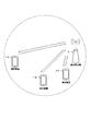
- FIG. 1 is a conceptual diagram of a wireless communication system in the present embodiment.
- the radio communication system includes terminal apparatuses 1A to 1C and a base station apparatus 3.
- the terminal devices 1A to 1C are also referred to as terminal devices 1.
- the following uplink physical channels are used in uplink wireless communication from the terminal device 1 to the base station device 3.
- the uplink physical channel is used to transmit information output from an upper layer.
- -PUCCH Physical Uplink Control Channel
- PUSCH Physical Uplink Shared Channel
- PRACH Physical Random Access Channel
- the PUCCH is used for transmitting uplink control information (Uplink Control Information: UCI).
- the uplink control information may include channel state information (CSI: Channel State Information) used to indicate the state of the downlink channel.
- CSI Channel State Information
- the uplink control information may include a scheduling request (SR: “Scheduling” Request) used for requesting the UL-SCH resource.
- SR scheduling request
- the uplink control information may include HARQ-ACK (Hybrid Automatic Repeat request ACKnowledgement).
- HARQ-ACK may indicate HARQ-ACK for downlink data (Transport block, Medium access Control, Protocol, Data, Unit: MAC-PDU, Downlink-Shared Channel: DL-SCH, Physical Downlink Shared Channel: PDSCH). . That is, HARQ-ACK may indicate ACK (acknowledgement) or NACK (negative-acknowledgement). HARQ-ACK is also referred to as ACK / NACK, HARQ feedback, HARQ response, HARQ information, or HARQ control information.
- the PUSCH is used to transmit uplink data (Uplink-Shared Channel: “UL-SCH,“ UL-SCH ”data).
- the PUSCH may also be used to transmit HARQ-ACK and / or CSI along with uplink data.
- the PUSCH may be used to transmit only CSI, or only HARQ-ACK and CSI. That is, PUSCH may be used to transmit only uplink control information.
- the base station device 3 and the terminal device 1 exchange (transmit / receive) signals in a higher layer.
- the base station device 3 and the terminal device 1 transmit and receive RRC signaling (RRC message: Radio Resource Control message, RRC information: also called Radio Resource Control information) in a radio resource control (RRC: Radio Resource Control) layer. May be.
- RRC Radio Resource Control
- the base station device 3 and the terminal device 1 may transmit and receive a MAC control element in a MAC (Medium Access Control) layer.
- MAC Medium Access Control
- the RRC signaling and / or the MAC control element is also referred to as a higher layer signal.
- the PUSCH may be used to transmit RRC signaling and MAC control elements.
- the RRC signaling transmitted from the base station apparatus 3 may be common signaling for a plurality of terminal apparatuses 1 in the cell.
- the RRC signaling transmitted from the base station device 3 may be signaling dedicated to a certain terminal device 1 (also referred to as dedicated signaling). That is, user device specific (user device specific) information may be transmitted to a certain terminal device 1 using dedicated signaling.
- PRACH is used to transmit a random access preamble.
- PRACH may also be used to indicate initial connection establishment (initial ⁇ ⁇ ⁇ ⁇ ⁇ ⁇ ⁇ ⁇ connection establishment) procedures, handover procedures, connection re-establishment procedures, synchronization for uplink transmissions (timing adjustment), and PUSCH resource requirements. Good.
- the following uplink physical signals are used in uplink wireless communication.
- the uplink physical signal is not used for transmitting information output from the higher layer, but is used by the physical layer.
- UL RS Uplink Reference Signal
- DMRS Demodulation Reference Signal
- SRS Sounding Reference Signal
- DMRS is related to transmission of PUSCH or PUCCH.
- DMRS is time-multiplexed with PUSCH or PUCCH.
- the base station apparatus 3 uses DMRS to perform propagation channel correction for PUSCH or PUCCH.
- transmitting both PUSCH and DMRS is simply referred to as transmitting PUSCH.
- transmitting both PUCCH and DMRS is simply referred to as transmitting PUCCH.
- SRS is not related to PUSCH or PUCCH transmission.
- the base station apparatus 3 uses SRS to measure the uplink channel state.
- the following downlink physical channels are used in downlink wireless communication from the base station apparatus 3 to the terminal apparatus 1.
- the downlink physical channel is used to transmit information output from an upper layer.
- PBCH Physical Broadcast Channel
- PCFICH Physical Control Format Indicator Channel
- PHICH Physical Hybrid automatic repeat request Indicator Channel
- PDCCH Physical Downlink Control Channel
- EPDCCH Enhanced Physical Downlink Control Channel
- PDSCH Physical Downlink Shared Channel
- PMCH Physical Multicast Channel
- the PBCH is used to broadcast a master information block (Master Information Block: MIB, Broadcast Channel: BCH) commonly used in the terminal device 1.
- MIB Master Information Block
- BCH Broadcast Channel
- PCFICH is used for transmitting information indicating a region (OFDM symbol) used for transmission of PDCCH.
- the PHICH is used to transmit an HARQ indicator (HARQ feedback, response information) indicating ACK (ACKnowledgement) or NACK (Negative ACKnowledgement) for uplink data (Uplink Shared Channel: UL-SCH) received by the base station apparatus 3. It is done.
- HARQ indicator HARQ feedback, response information
- ACK acknowledgement
- NACK Negative ACKnowledgement
- DCI Downlink Control Information
- a plurality of DCI formats are defined for transmission of downlink control information. That is, fields for downlink control information are defined in the DCI format and mapped to information bits.
- a DCI format for the downlink a DCI format used for scheduling one PDSCH (transmission of one downlink transport block) in one cell (for example, DCI format 1, DCI format 1A, and / or DCI format 1C) may be defined.
- the DCI format for the downlink includes information related to PDSCH scheduling.
- the DCI format for the downlink includes a carrier indicator field (CIF: Carrier Indicator Field), information on HARQ process number (HARQ process number), information on MCS (Modulation and Coding Scheme), information on redundancy version (Redundancy version) And / or downlink control information such as information on resource block assignment (Resource block assignment).
- the DCI format for the downlink is also referred to as a downlink grant and / or a downlink assignment.
- DCI formats for example, DCI format 0, DCI format 4 used for scheduling one PUSCH (transmission of one uplink transport block) in one cell are used. Defined.
- the information on PUSCH scheduling is included in the DCI format for the uplink.
- the DCI format for uplink includes a carrier indicator field (CIF: Carrier Indicator Field), information on a transmission power command (TPC command) for a scheduled PUSCH (TPC command for scheduled PUSCH), information on a cyclic shift for DMRS (Cyclic shift DMRS), information about MCS and / or redundancy version (Modulation and coding scheme and / or redundancy version), and / or information about resource block allocation and / or hopping resource allocation (Resource block assignment and / or hopping resource) allocation) and downlink control information such as a CSI request field.
- the DCI format for the uplink is also referred to as an uplink grant and / or an uplink assignment.
- the CSI request field may be a field mapped to information (CSI request) used to request transmission of CSI. That is, the CSI request field may be used for requesting (instructing) transmission of CSI.
- the base station apparatus 3 may trigger CSI transmission (also referred to as aperiodic CSI report) using PUSCH by setting to trigger a report using the CSI request field.
- the terminal device 1 may perform aperiodic CSI reporting when it is set to trigger a report using the CSI request field.
- the base station apparatus 3 may be set to trigger a report by using a CSI request field (1 bit CSI request field) set to '1'. Also, the base station apparatus 3 is set to trigger a report by using the CSI request field (2-bit CSI request field) set to '01', '10', or '11'. Also good. Similarly, the base station apparatus 3 may be set to trigger a report using a 3-bit CSI request field.
- aperiodic CSI reporting may be performed using PUSCH.
- the terminal device 1 may receive the downlink data using the scheduled PDSCH. Moreover, when the PUSCH resource is scheduled using the uplink grant, the terminal device 1 may transmit the uplink data and / or the uplink control information using the scheduled PUSCH.
- the terminal device 1 may monitor a set of PDCCH candidates (PDCCH candidates) and / or EPDCCH candidates (EPDCCH candidates).
- PDCCH may indicate PDCCH and / or EPDDCH.
- the PDCCH candidate indicates a candidate in which the PDCCH may be arranged and / or transmitted by the base station apparatus 3.
- the term “monitor” may include the meaning that the terminal apparatus 1 attempts to decode each PDCCH in the set of PDCCH candidates according to all the DCI formats to be monitored.
- the set of PDCCH candidates that the terminal device 1 monitors is also referred to as a search space.
- the search space may include a common search space (CSS: Common Search Space).
- the CSS may be defined as a common space for the plurality of terminal devices 1.
- the search space may include a user device specific search space (USS: “UE-specific” Search “Space”).
- USS user device specific search space
- the USS may be defined based on at least a C-RNTI assigned to the terminal device 1.
- the terminal device 1 may monitor the PDCCH and detect the PDCCH addressed to itself in CSS and / or USS.
- the RNTI assigned to the terminal device 1 by the base station device 3 is used for transmission of the downlink control information (transmission on the PDCCH).
- a CRC (Cyclic Redundancy Check) parity bit is added to the DCI format (which may be downlink control information), and after the CRC parity bit is added, the CRC parity bit is scrambled by the RNTI.
- the CRC parity bit added to the DCI format may be obtained from the payload of the DCI format.
- the terminal device 1 tries to decode the DCI format to which the CRC parity bit scrambled by the RNTI is added, and detects the DCI format in which the CRC is successful as the DCI format addressed to itself (also referred to as blind decoding). ) That is, the terminal device 1 may detect the PDCCH accompanied by the CRC scrambled by the RNTI. Further, the terminal device 1 may detect a PDCCH accompanied by a DCI format to which a CRC parity bit scrambled by RNTI is added.
- the RNTI may include a C-RNTI (Cell-Radio Network Temporary Identifier).
- the C-RNTI is a unique (unique) identifier for the terminal device 1 used for RRC connection and scheduling identification.
- C-RNTI may also be used for dynamically scheduled unicast transmissions.
- RNTI may include SPS C-RNTI (Semi-Persistent Scheduling C-RNTI).
- SPS C-RNTI Semi-Persistent Scheduling C-RNTI
- the SPS C-RNTI is a unique (unique) identifier for the terminal device 1 used for semi-persistent scheduling (SPS).
- SPS C-RNTI may also be used for semi-persistently scheduled unicast transmissions.
- semi-persistently scheduled transmission includes the meaning of transmission scheduled periodically.
- the SPS C-RNTI may be used for semi-persistently scheduled transmission activation, reactivation, and / or retransmission.
- activation may include the meaning of reactivation and / or retransmission.
- the SPS C-RNTI may also be used for the release and / or deactivation of semi-persistently scheduled transmissions.
- the release may include the meaning of deactivation.
- a new RNTI may be defined to reduce the waiting time.
- the SPS C-RNTI in this embodiment may include a newly defined RNTI for reducing the waiting time.
- the PDSCH is used to transmit downlink data (Downlink Shared Channel: DL-SCH).
- the PDSCH is used for transmitting a system information message.
- the system information message may be cell specific (cell specific) information.
- System information is included in RRC signaling.
- the PDSCH is used to transmit RRC signaling and a MAC control element.
- PMCH is used to transmit multicast data (Multicast Channel: MCH).
- the following downlink physical signals are used in downlink wireless communication.
- the downlink physical signal is not used for transmitting information output from the upper layer, but is used by the physical layer.
- SS Synchronization signal
- DL RS Downlink Reference Signal
- the synchronization signal is used for the terminal device 1 to synchronize the downlink frequency domain and time domain.
- the synchronization signal is arranged in subframes 0, 1, 5, and 6 in the radio frame.
- the synchronization signal is arranged in subframes 0 and 5 in the radio frame.
- the downlink reference signal is used for the terminal device 1 to correct the propagation path of the downlink physical channel.
- the downlink reference signal is used for the terminal apparatus 1 to calculate downlink channel state information.
- the following five types of downlink reference signals are used.
- -CRS Cell-specific Reference Signal
- URS UE-specific Reference Signal
- PDSCH PDSCH
- DMRS Demodulation Reference Signal
- EPDCCH Non-Zero Power Chanel State Information-Reference Signal
- ZP CSI-RS Zero Power Chanel State Information-Reference Signal
- MBSFN RS Multimedia Broadcast and Multicast Service over Single Frequency Network Reference signal
- PRS Positioning Reference Signal
- the downlink physical channel and the downlink physical signal are collectively referred to as a downlink signal.
- the uplink physical channel and the uplink physical signal are collectively referred to as an uplink signal.
- the downlink physical channel and the uplink physical channel are collectively referred to as a physical channel.
- the downlink physical signal and the uplink physical signal are collectively referred to as a physical signal.
- BCH, MCH, UL-SCH and DL-SCH are transport channels.
- a channel used in a medium access control (Medium Access Control: MAC) layer is referred to as a transport channel.
- a transport channel unit used in the MAC layer is also referred to as a transport block (transport block: TB) or a MAC PDU (Protocol Data Unit).
- HARQ HybridbrAutomatic Repeat reQuest
- the transport block is a unit of data that the MAC layer delivers to the physical layer.
- the transport block is mapped to a code word, and an encoding process is performed for each code word.
- one or a plurality of serving cells may be set for the terminal device 1.
- a technique in which the terminal device 1 communicates via a plurality of serving cells is referred to as cell aggregation or carrier aggregation.
- the present embodiment may be applied to each of one or a plurality of serving cells set for the terminal device 1. Further, the present embodiment may be applied to a part of one or a plurality of serving cells set for the terminal device 1. In addition, the present embodiment may be applied to each of one or a plurality of serving cell groups set for the terminal device 1.
- TDD Time Division Duplex
- FDD Frequency Division Duplex
- TDD or FDD may be applied to all of one or a plurality of serving cells.
- a serving cell to which TDD is applied and a serving cell to which FDD is applied may be aggregated.
- the frame structure corresponding to FDD is also referred to as “frame structure type 1”.
- the frame structure corresponding to TDD is also referred to as “frame structure type 2”.
- the set one or more serving cells may include one primary cell and one or more secondary cells.
- a primary cell is a serving cell that has undergone an initial connection establishment (initial connection establishment) procedure, a serving cell that has initiated a connection re-establishment procedure, or a cell designated as a primary cell in a handover procedure. May be.
- the secondary cell may be set at the time when the RRC connection is established or later.
- a carrier corresponding to a serving cell is referred to as a downlink component carrier.
- a carrier corresponding to a serving cell is referred to as an uplink component carrier.
- the downlink component carrier and the uplink component carrier are collectively referred to as a component carrier.
- the terminal device 1 may perform transmission and / or reception on a plurality of physical channels simultaneously in one or a plurality of serving cells (component carriers).
- one physical channel may be transmitted in one serving cell (component carrier) among a plurality of serving cells (component carriers).
- FIG. 2 is a diagram showing a configuration of slots in the present embodiment.
- the horizontal axis represents the time axis
- the vertical axis represents the frequency axis.
- normal CP normal Cyclic Prefix
- extended CP extended Cyclic Prefix
- a physical signal or physical channel transmitted in each slot is represented by a resource grid.
- each radio frame may include 10 subframes continuous in the time domain.
- each subframe i may include two consecutive slots in the time domain.
- the two consecutive slots in the time domain may be a slot with a slot number n s of 2i in the radio frame and a slot with a slot number n s of 2i + 1 in the radio frame.
- each radio frame may include 10 subframes that are continuous in the time domain.
- the field in the time domain is also referred to as TTI (Transmission Time Interval).
- the resource grid may be defined by a plurality of subcarriers and a plurality of OFDM symbols.
- a resource grid may be defined by a plurality of subcarriers and a plurality of SC-FDMA symbols.
- the number of subcarriers constituting one slot may depend on the cell bandwidth.
- the number of OFDM symbols or SC-FDMA symbols constituting one slot may be seven.
- each of the elements in the resource grid is referred to as a resource element.
- the resource element may be identified using a subcarrier number and an OFDM symbol or SC-FDMA symbol number.
- the resource block may be used to express a mapping of a certain physical channel (such as PDSCH or PUSCH) to a resource element.
- virtual resource blocks and physical resource blocks may be defined as resource blocks.
- a physical channel may first be mapped to a virtual resource block. Thereafter, the virtual resource block may be mapped to a physical resource block.
- One physical resource block may be defined from 7 consecutive OFDM symbols or SC-FDMA symbols in the time domain and 12 consecutive subcarriers in the frequency domain. Therefore, one physical resource block may be composed of (7 ⁇ 12) resource elements.
- One physical resource block may correspond to one slot in the time domain and 180 kHz in the frequency domain.
- physical resource blocks may be numbered from 0 in the frequency domain.
- a MAC entity in the terminal device 1 a “Multiplexing and assembly” entity (hereinafter also referred to as a first entity) in the terminal device 1, and / or The process in the HARQ entity in the terminal device 1 is described. That is, in the present embodiment, processing in the MAC entity in the terminal device 1, the first entity in the terminal device 1, and / or the HARQ entity in the terminal device 1 is described. Of course, this is a process in the apparatus 1.
- the operation (processing) in the terminal device 1 is basically described, but the base station device 3 performs the same operation (processing) corresponding to the operation (processing) of the terminal device 1.
- the base station device 3 performs the same operation (processing) corresponding to the operation (processing) of the terminal device 1.
- transmission on PUSCH may be performed at a timing based on SFN (System (Fame Number) and subframes. That is, in order to specify the timing of transmission on PUSCH, the SFN and the subframe number / index in the radio frame corresponding to the SFN are required.
- SFN is a radio frame number / index.
- the SFN (radio frame) and subframe in which transmission is performed on the PUSCH are also simply referred to as subframes. That is, the subframe in the following description may include the meaning of SFN (radio frame) and subframe.
- the base station apparatus 3 may set an interval (period) of semi-persistent scheduling in the uplink for the terminal apparatus 1.
- the base station apparatus 3 may include the first parameter for indicating the value of the semi-persistent scheduling interval in the uplink in the upper layer signal (RRC message) and transmit the first parameter to the terminal apparatus 1. .
- the base station apparatus 3 uses the first parameter as the value of the semi-persistent scheduling interval, 1 (1 subframe), 10 (10 subframes), 20 (20 subframes), 32 (32 Subframe), 40 (40 subframe), 64 (64 subframe), 80 (80 subframe), 128 (128 subframe), 160 (160 subframe), 320 (320 subframe), and / or 640 (640 subframes) may be set. That is, the base station apparatus 3 may set 1 (one subframe) as the value of the semi-persistent scheduling interval using the first parameter.
- the first parameter may be set for each serving cell (primary cell and / or secondary cell). Also, the first parameter may be set for the primary cell.
- the semi-persistent scheduling interval value “1 (1 subframe)” may be set for each serving cell (primary cell and / or secondary cell).
- the base station apparatus 3 uses the DCI format (for example, DCI format 0) for the uplink, and uses the PUSCH resource (semi-persistent, semi-persistent, periodic) for the terminal apparatus 1 (PUSCH resource).
- the terminal apparatus 1 may be instructed to allocate a physical resource block) and to activate transmission on a semi-persistent PUSCH.
- the base station apparatus 3 may instruct the terminal apparatus 1 to release semi-persistent PUSCH resources using the DCI format for the uplink.
- the CSI request field may be included in the DCI format for the uplink.
- the CRC parity bit added to the DCI format is scrambled by the SPS C-RNTI, and the information field regarding the new data indicator included in the DCI format is set to '0'. If it is, it may be verified (confirmed or checked) whether a plurality of information fields included in the DCI format are set to specific values. That is, the CRC parity bits added to the DCI format scrambled by the SPS C-RNTI and the information field regarding the new data indicator may be used for validation for semi-persistent scheduling.
- the terminal apparatus 1 considers that the received DCI format indicates a valid semi-persistent activation or a valid semi-persistent release. Good (may be recognized). If the verification is not successful, the terminal device 1 may discard (clear) this DCI format.
- semi-persistent activation may include the meaning of semi-persistent scheduling activation.
- the semi-persistent activation may include the meaning of semi-persistent allocation of PUSCH resources.
- the semi-persistent release may include the meaning of semi-persistent scheduling release.
- the DCI format may be used to indicate the activation of semi-persistent uplink scheduling.
- the DCI format may also be used to enable activation of semi-persistent scheduling.
- the DCI format may also be used to indicate semi-persistent release.
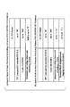
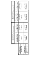
- FIG. 3 is a diagram showing an example of special fields related to semi-persistent scheduling.
- FIG. 3A shows an example of a special field for activation of semi-persistent scheduling.
- FIG. 3B shows an example of a special field for the release of semi-persistent scheduling.
- the DCI including the special field shown in FIG. 3A is also referred to as a first DCI.
- the DCI including the special field shown in FIG. 3B is also referred to as a second DCI.
- the first DCI may be a DCI used for instructing activation of semi-persistent scheduling.
- the first DCI may be a DCI used for instructing activation and / or reactivation of semi-persistent scheduling.
- the second DCI may be a DCI used for instructing activation of semi-persistent scheduling.
- multiple fields may be defined for activation and / or release of semi-persistent scheduling (in the first DCI and / or the second DCI).
- a predetermined value (which may be a specific value) set in each of a plurality of fields may be defined for activation and / or release of semi-persistent scheduling.
- the DCI format for the uplink (eg, DCI format 0) is used for the activation of the semi-persistent schedule
- information on the TPC command for the scheduled PUSCH included in the DCI format for the uplink (TPC command for scheduled PUSCH) is set to '00'
- the cyclic shift information for DMRS (Cyclic shift DMRS) is set to '000'
- the information about MCS and redundancy version (Modulation and coding scheme and redundancy version ) Field (MSB: most significant'bit) may be set to '0'.
- a DCI format for uplink for example, DCI format 0
- TPC command for The scheduled (PUSCH) field is set to '00'
- the cyclic shift information for DMRS Cyclic shift DMRS
- the MCS and redundancy version information Modulation and coding scheme and redundancy version
- the resource block allocation and hopping resource allocation information (Resource block allocation and hopping resource allocation) fields Field (or in all fields of the plurality of fields) may be '1' sets.
- the terminal device 1 may activate the semi-persistent scheduling when each of the plurality of information fields included in the DCI format for the uplink is set to a specific value defined in advance. Further, the terminal device 1 may release semi-persistent scheduling when each of a plurality of information fields included in the DCI format is set to a predetermined specific value.
- a plurality of information fields used for activation and / or release of semi-persistent scheduling, and a predetermined value in which the information fields are set are not limited to the above-described example.
- a plurality of information fields used for activation and / or release of semi-persistent scheduling, and a predetermined value in which the information fields are set are defined in advance according to specifications or the like. It may be known information between the station device 3 and the terminal device 1.
- a value defined in advance for the release may be set in a field related to resource block allocation (resource allocation).
- the terminal device 1 in order to perform transmission on the UL-SCH (transmission on the UL-SCH via the PUSCH, transmission of the UL-SCH on the PUSCH), the terminal device 1 has an effective uplink grant (a valid uplink grant ) Must have.
- the uplink grant may include the meaning that uplink transmission in a certain subframe is granted (granted or given).
- a valid uplink grant may be dynamically received on the PDCCH. That is, a valid uplink grant may be indicated using a DCI format to which CRC parity bits scrambled by C-RNTI are added.
- a valid uplink grant may be set semi-permanently. That is, a valid uplink grant may be indicated using a DCI format to which CRC parity bits scrambled by SPS C-RNTI are added.
- the terminal device 1 may store the uplink grant that is dynamically received on the PDCCH and / or the uplink grant that is set semipermanently.
- the HARQ entity passes the uplink grant dynamically received on the PDCCH and / or the semi-permanently configured uplink grant to the HARQ process, and the HARQ process receives the uplink grant received from the HARQ entity.
- Link grants may be stored.
- the uplink grant dynamically received on the PDCCH and / or the uplink grant set semi-permanently is referred to as a stored uplink grant (a stored uplink grant).
- the terminal device 1 stores the DCI format received from the base station device 3 as an uplink grant to be set (a configured uplink grant). May be.
- the set uplink grant may be referred to as a set semi-persistent scheduling uplink grant (SPS UL grant) or set grant.
- the configured uplink grant may be referred to as a configured uplink grant, a configured semi-persistent scheduling uplink grant (SPS UL grant), or a configured grant.
- the uplink grant (SPS UL grant) stored by the HARQ process may not be cleared based on the uplink grant (SPS UL grant) stored by the MAC entity being cleared. That is, even if the uplink grant (SPS UL (grant) stored by the MAC entity is cleared, retransmission to the semi-persistent PUSCH is performed based on the uplink grant (SPS UL grant) stored by the HARQ process. It is possible to continue.
- the uplink grant of semi-persistent scheduling may also be referred to as SPS uplink grant, semi-persistent grant, or semi-persistent scheduling assignment.
- the base station apparatus 3 may set the terminal apparatus 1 to enable and / or disable semi-persistent scheduling. For example, the base station apparatus 3 may set the validity and / or the invalidity of semi-persistent scheduling using an upper layer signal (for example, an RRC layer signal).
- an upper layer signal for example, an RRC layer signal
- the terminal device 1 starts transmission on a semi-persistent PUSCH in a certain subframe, and repeats transmission on the semi-persistent PUSCH based on the number (1).
- the configured uplink grant may be initialized or reinitialized. That is, the terminal device 1 may be regarded continuously when the set uplink grant occurs in the subframe satisfying the formula (1).
- the terminal apparatus 1 sets the value of Subframe_Offset (subframe offset), and sets the Nth grant (set) in the subframe specified based on the number (1).
- Uplink grant, SPS uplink grant) may occur (occurrence) (consider sequentially).
- a subframe that satisfies the number (1) is also referred to as a subframe that satisfies a predetermined condition.
- subframes excluding the first subframe among the subframes satisfying the formula (1) are also referred to as subframes that satisfy a predetermined condition.
- the first subframe among the subframes satisfying the number (1) may be a subframe that receives the first DCI.
- the terminal device 1 sets a subframe for transmission on the PUSCH corresponding to the Nth set uplink grant based on the number (1).
- SFN and subframe indicate an SFN and a subframe in which transmission on PUSCH is performed, respectively.
- SFN start_time and subframe start_time indicate the SFN and subframe at the time when the configured uplink grant is initialized or reinitialized , respectively. That is, the SFN start_time and the subframe start_time are based on the configured uplink grant, the SFN that starts transmission on the PUSCH and the subframe (that is, initial transmission on the PUSCH corresponding to the 0th configured uplink grant) Is a subframe).
- semiPersistSchedIntervalUL indicates a semi-persistent scheduling interval in the uplink.
- Subframe_Offset indicates an offset value used for specifying a subframe in which transmission is performed on the PUSCH.
- the terminal device 1 sets the Subframe_Offset in the number (1) to “0” if the parameter (twoIntervalConfig) is not enabled by the upper layer. May be.
- initialization may be performed when semi-persistent scheduling is not activated. Reinitialization may also be performed when semi-persistent scheduling is already active.
- initialization may include the meaning of initial setting, and reinitialization may include the meaning of reinitialization. That is, the terminal device 1 may start transmission on the PUSCH in a certain subframe by initializing or reinitializing the configured uplink grant.
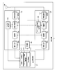
- FIG. 4 is a diagram for explaining an example of non-empty transmission (Empty transmission).
- the MAC protocol data unit (MAC PDU: MAC Protocol Protocol Data Unit) includes a MAC header (MAC header), a MAC service data unit (MAC SDU: MAC Service Data Unit), and a MAC control element (MAC CE: MAC Control Element) and padding (padding bit).
- the MAC protocol data unit may correspond to uplink data (UL-SCH).
- a plurality of MAC control elements including at least a MAC control element to be described later may be defined as the MAC control element.
- a buffer status report MAC control element BSR MAC CE: Buffer Status Report MAC CE, a MAC control element used for a buffer status report
- BSR MAC CE Buffer Status Report MAC CE
- a timing advance command MAC control element TAC MAC CE: Timing Advance Command MAC CE, MAC control element used for transmission of timing advance command
- TAC MAC CE Timing Advance Command MAC CE, MAC control element used for transmission of timing advance command
- a power headroom report MAC control element (PHR MAC: CE: Power Headroom Report MAC: CE, MAC control element used for power headroom report) may be defined.
- PHR MAC: CE: Power Headroom Report MAC: CE, MAC control element used for power headroom report may be defined.
- an activation / deactivation MAC control element (Activation / Deactivation MAC CE, a MAC control element used for transmission of an activation / deactivation command) may be defined as a MAC control element.
- a plurality of buffer status reports including at least regular BSR, periodic BSR, and padding BSR may be defined as buffer status reports.
- each of regular BSR, periodic BSR, and padding BSR may be triggered based on different events (conditions).
- a regular BSR can transmit data of a logical channel belonging to a certain ethical channel group (LCG: Logical Channel Group), and its transmission priority is higher than a logical channel that can be transmitted that belongs to any LCG It may be triggered if there is no data that can be transmitted on a logical channel belonging to any LCG.
- the regular BSR may be triggered when a predetermined timer (retx BSR-Timer) expires and the terminal device 1 has data that can be transmitted in a logical channel belonging to a certain LCG.
- the periodic BSR may be triggered when a predetermined timer (periodic BSR-Timer) expires.
- Padding BSR may also be triggered when UL-SCH is assigned and the number of padding bits is equal to or greater than the size of the buffer status report MAC control element and its subheader.
- the terminal device 1 may notify the base station device 3 of the uplink data transmission data buffer amount corresponding to each LCG as a message in the MAC layer using the buffer status report.
- a MAC protocol data unit may include zero, one, or multiple MAC service data units.
- the MAC protocol data unit may also include zero, one, or multiple MAC control elements.
- the padding may be added to the end of the MAC protocol data unit (Padding may occur at the end of the MAC PDU).
- the non-empty transmission may be a transmission of a MAC protocol data unit including at least one or more MAC service data units (a MAC protocol including at least one or more MAC service data units). May correspond to the transmission of data units).
- the non-empty transmission may be a transmission of a MAC protocol data unit including at least one or more first MAC control elements (including at least one or more first MAC control elements). , May support transmission of MAC protocol data units).
- the first MAC control element (first predetermined MAC control element) is defined in advance by a specification or the like, and may be known information between the base station device 3 and the terminal device 1.
- the first MAC control element may include one or all of the plurality of MAC control elements described above.
- the first MAC control element may be a power headroom report MAC control element.
- the first MAC control element may be a buffer status report MAC control element including a regular BSR.
- the first MAC control element may be a buffer status report MAC control element including a periodic BSR.
- a non-empty transmission may be a transmission of a MAC protocol data unit that includes one or more MAC service data units and / or one or more first MAC control elements (at least, May correspond to transmission of MAC protocol data units including one or more MAC service data units and / or one or more first MAC control elements).
- empty transmission may be transmission of a MAC protocol data unit including only padding (corresponding to transmission of a MAC protocol data unit including only padding).
- a MAC header may be added to transmission of a MAC protocol data unit including only padding.
- the empty transmission may be a transmission of a MAC protocol data unit including one or more second MAC control elements (including at least one or more second MAC control elements, May correspond to transmission of MAC protocol data units).
- the second MAC control element (second predetermined MAC control element) is defined in advance by a specification or the like, and may be known information between the base station device 3 and the terminal device 1.
- the second MAC control element may be a MAC control element other than the first MAC control element.
- the second MAC control element may include one or all of the plurality of MAC control elements described above.
- the second MAC control element may be a buffer status report MAC control element that includes a padding BSR.
- the empty transmission may be a transmission of a MAC protocol data unit that includes only padding and / or one or more second MAC control elements (padding only and / or one or May correspond to transmission of MAC protocol data units including a plurality of second MAC control elements).
- non-empty transmission and / or empty transmission may be transmission corresponding to initial transmission. That is, in the initial transmission, transmitting a MAC protocol data unit including at least one or more MAC service data units and / or one or more first MAC control elements is a non-empty transmission. May be referred to.
- transmission of a MAC protocol data unit including only padding and / or one or more second MAC control elements in the initial transmission may be referred to as empty transmission.
- non-empty transmission and / or empty transmission may be performed on the PUSCH scheduled by the base station apparatus 3.
- a non-empty transmission and / or an empty transmission may be a PUSCH scheduled using DCI (DCI format) with a CRC parity bit scrambled by C-RNTI (ie, dynamically scheduled PUSCH). Resource).
- non-empty transmission and / or empty transmission is PUSCH scheduled using DCI (DCI format) with CRC parity bits scrambled by SPS C-RNTI (ie, semi-permanently scheduled). (PUSCH resource).
- the terminal device 1 performs transmission on the PUSCH (transmission on the UL-SCH) semi-permanently (semi-persistent and periodic) in the subframe specified based on the number (1). Also good.
- the terminal device 1 is set based on a second parameter (a parameter for instructing the number of empty transmissions before release (Number ⁇ of empty transmissions before release)) set by the base station device 3. You may clear the configured grant.
- the terminal device 1 when the number of empty transmissions corresponding to the initial transmission in the continuous semi-persistent PUSCH reaches the value (number of transmissions) indicated by using the second parameter, the terminal device 1 The set grant may be cleared.
- each terminal apparatus 1 is a MAC protocol data unit that does not include a MAC service data unit (that is, includes zero MAC service data unit), and corresponds to the number of consecutive new MAC protocol data units.
- the configured grant may be cleared (may (clear the configured grant immediately after the third parameter number of consecutive new MAC PDUs each containing zero MAC SDUs).
- the number of consecutive empty transmissions corresponding to the initial transmission may include the number of empty transmissions in the semi-persistent scheduling resource.
- the number of empty transmissions corresponding to successive initial transmissions may not include the number of empty transmissions on dynamically scheduled PUSCH resources.
- the terminal apparatus 1 may release (clear) the uplink resources (semi-persistent scheduling resource, PUSCH resource) allocated by the base station apparatus 3 based on the second parameter. That is, the terminal device 1 may release the uplink resource allocated by the base station device 3 based on the second parameter, similarly to clearing the set grant.
- the terminal device 1 when receiving the DCI format used for instructing the release of the above-described semi-persistent scheduling, the terminal device 1 clears the set grant and / or releases the uplink resource. Also good.
- transmission of uplink data is performed by the terminal device 1, and based on the second parameter, an operation of clearing a set grant and / or releasing uplink resources is performed. This is also referred to as a first operation. Further, as described above, when the uplink data is transmitted by the terminal device 1 and the DCI format used for instructing the release of the semi-persistent scheduling is received, the set grant is cleared, and / or Alternatively, an operation in which uplink resources are released is also referred to as a first operation.
- the terminal apparatus 1 when the terminal apparatus 1 receives the DCI format used for instructing the release of the semi-persistent scheduling, the terminal apparatus 1 immediately clears the set grant and / or the uplink. Release link resources. That is, when receiving the DCI format used for instructing the release of semi-persistent scheduling, the terminal device 1 immediately sends the set grant without transmitting any information to the base station device 3. Clear and / or release uplink resources.
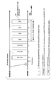
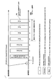
- FIG. 5 is a diagram illustrating an example of an uplink transmission method according to this embodiment.
- FIG. 5 may show a transmission method (processing method) in the first operation.
- FIG. 5 shows an operation when “1 (1 subframe)” is set as an interval value of semi-persistent scheduling as an example.
- the transmission shown in FIG. 5 shows, for example, transmission with resources of semi-persistent scheduling.
- the terminal apparatus 1 receives the first DCI (DCI (DCI format, uplink grant, SPS activation command) used to instruct activation and / or reactivation of semi-persistent scheduling). You may receive it.
- the terminal apparatus 1 performs non-empty transmission in a subframe corresponding to the subframe that has received the first DCI (for example, a subframe four subframes after the subframe i, subframe n1). Also good.
- the terminal device 1 may perform empty transmission.
- the terminal device 1 may execute non-empty transmission based on the set uplink grant according to the number (1) described above. That is, in a case where there is data available for transmission (available data for transmission), the terminal device 1 may perform non-empty transmission with semi-persistent scheduling resources. Further, when there is no data available for transmission, the terminal device 1 may execute empty transmission with a resource for semi-persistent scheduling. Similarly, in subframe n2, subframe 3, subframe 4, subframe 5, subframe 6, and / or subframe 7, terminal apparatus 1 performs non-empty transmission and / or empty transmission. May be.
- the case of having data available for transmission is (i) “only padding BSR is not available for transmission” (a case that “not only padding BSR is available for transmission”) Or (ii) “Padding BSR and / or only padding is not available for transmission” (a case that “not only padding BSR and / or padding is (are) available for transmission”) May be included. That is, the case of having data available for transmission may include the case where only the padding BSR is not available for transmission. In other words, the case of having data available for transmission may include a case where only padding BSR and / or padding is not available for transmission.
- the padding BSR may be a second MAC control element. That is, the padding BSR may be a buffer status report MAC control element including the padding BSR.
- the terminal device 1 when the number of consecutive empty transmissions in the semi-persistent scheduling resource reaches the value (number of transmissions) set using the second parameter, the terminal device 1 The set grant may be cleared (indicated by 500 in FIG. 5). Further, when the number of consecutive empty transmissions in the semi-persistent scheduling resource reaches the value (number of transmissions) set using the second parameter, the terminal apparatus 1 determines that the uplink resource (Semi-persistent scheduling resource) may be released. That is, the terminal device 1 may clear the set grant and / or release uplink resources based on the second parameter.
- the terminal device 1 receives the second DCI (DCI (DCI format, uplink grant, SPS release command) used to instruct the release of semi-persistent scheduling). Also good. As described above, when receiving the second DCI, the terminal device 1 may immediately clear the set grant and / or release the uplink resource. That is, when the terminal device 1 receives the second DCI, the terminal device 1 immediately clears the set grant and / or allocates uplink resources without transmitting any information to the base station device 3. May be released.
- DCI DCI format, uplink grant, SPS release command
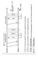
- FIG. 6 is another diagram for explaining a transmission method in the uplink in the present embodiment.
- the operation described with reference to FIG. 6 is also referred to as a second operation.
- FIG. 6 shows an operation when “1 (1 subframe)” is set as an interval value of semi-persistent scheduling as an example.
- the transmission shown in FIG. 6 shows, for example, transmission with resources of semi-persistent scheduling.
- the base station apparatus 3 may transmit a third parameter (also referred to as skipUplinkTxSPS) to the terminal apparatus 1.
- the base station apparatus 3 may transmit the third parameter using a higher layer signal (for example, a signal in the RRC layer).
- the third parameter may include a parameter used to set execution of the second operation (may be a part of the operation included in the second operation).
- the third parameter may include a parameter used to set a value “1 (1 subframe)” of the semi-persistent scheduling in the uplink.
- the third parameter may include a parameter used to set whether to execute (execute or not execute) empty transmission with a semi-persistent scheduling resource. Further, the third parameter may include a parameter used for setting whether to execute non-empty transmission with a resource of semi-persistent scheduling (execution or non-execution).
- the terminal device 1 may switch between the first operation and the second operation based on the third parameter (for example, the parameter in the higher layer, the parameter in the RRC layer) transmitted by the base station device 3. .
- the terminal device 1 may execute the first operation when the third parameter is not set, and may execute the second operation when the third parameter is set.
- the terminal device 1 may receive the first DCI.
- the terminal device 1 does not perform empty transmission in a subframe corresponding to the subframe that has received the first DCI (for example, a subframe four subframes after the subframe i, subframe n1). Further, the terminal device 1 may perform non-empty transmission in the subframe n1.
- the terminal device 1 that does not have data available for transmission does not execute empty transmission. That is, the terminal device 1 skips empty transmission. That is, the terminal device 1 skips the uplink grant (the configured grant). That is, the terminal device 1 may skip transmission in the uplink. Further, in the subframe n1, the terminal device 1 having data usable for transmission may execute non-empty transmission.
- the terminal device 1 in which the third parameter is set does not perform empty transmission when there is no data available for transmission.
- the terminal device 1 in which the third parameter is not set performs empty transmission when there is no data available for transmission. That is, the terminal device 1 may switch whether to perform empty transmission or not to perform empty transmission when there is no data available for transmission based on the third parameter.
- the terminal apparatus 1 when the terminal apparatus 1 performs transmission corresponding to DCI (DCI format, uplink grant) to which CRC parity bits scrambled by C-RNTI are added, the terminal apparatus 1 is always non-empty. Transmission or empty transmission may be performed. That is, when the PUSCH resource is scheduled using the DCI to which the CRC parity bit scrambled by C-RNTI is added, the terminal apparatus 1 always uses the scheduled PUSCH resource to be non-empty. Transmission or empty transmission may be performed.
- DCI DCI format, uplink grant
- resources scheduled using DCI with dynamically added CRC parity bits scrambled by C-RNTI are added CRC parity bits scrambled by SPS C-RNTI.
- Resources scheduled using DCI may be overridden.
- the terminal device 1 having data usable for transmission may perform non-empty transmission. Further, in the subframe n2 and / or the subframe 3, the terminal device 1 that does not have data usable for transmission does not have to execute empty transmission. That is, the terminal device 1 having data that can be used for transmission does not perform the padding BSR and / or the padding-only transmission.
- the terminal device 1 in which the third parameter is set has data that can be used for transmission, and is given an uplink grant corresponding to semi-persistent scheduling, may execute non-empty transmission.
- the terminal device 1 in which the third parameter is set has no usable data for transmission, and is given an uplink grant corresponding to semi-persistent scheduling, does not execute empty transmission. Also good.
- the terminal device 1 that has data that can be used for transmission and is given an uplink grant corresponding to dynamic scheduling is configured to be non-empty. Transmission may be performed. Regardless of whether or not the third parameter is set, the terminal device 1 that has no usable data for transmission and is given an uplink grant corresponding to dynamic scheduling is Transmission may be performed.
- the terminal device 1 may receive the second DCI.
- the terminal device 1 corresponds to the subframe corresponding to the subframe that has received the second DCI (for example, the subframe four subframes after the subframe i + x). In the frame and subframe n6), it is not necessary to perform empty transmission.
- the terminal device 1 having data available for transmission may perform non-empty transmission. That is, the terminal device 1 having data that can be used for transmission does not perform the padding BSR and / or the padding-only transmission.
- the terminal apparatus 1 uses the most recent DCI (the latest first DCI) used to instruct activation and / or deactivation of semi-persistent scheduling.
- Non-empty transmission may be performed on a PUSCH (PUSCH resource) scheduled by DCI 1).
- the latest first DCI is also referred to as the last received DCI.
- the terminal device 1 when the terminal device 1 has data available for transmission, the terminal device 1 performs non-empty transmission on the PUSCH (PUSCH resource) scheduled by the stored grant (the ⁇ ⁇ ⁇ configured grant). May be executed. That is, in the subframe n7, the terminal device 1 having data that can be used for transmission may execute non-empty transmission based on a set grant (the configured grant).
- a value defined in advance for the release of semi-persistent scheduling may be set in a field related to resource block allocation (resource allocation). Therefore, when the terminal device 1 receives the second DCI, the terminal device 1 may execute non-empty transmission based on a set grant (the “configured” grant).
- the terminal apparatus 1 may execute non-empty transmission based on a set grant. That is, when receiving the second DCI, the terminal device 1 may perform non-empty transmission using the PUSCH (PUSCH resource) before releasing the PUSCH (PUSCH resource).
- PUSCH (PUSCH resource) is scheduled by the latest first DCI. That is, PUSCH (PUSCH resource) is scheduled by a set grant (the configured grant).
- the terminal device 1 clears the set grant and / or releases uplink resources in a subframe in which non-empty transmission is performed or a subframe after the subframe in which non-empty transmission is performed. It may be (indicated by 600 in FIG. 6). That is, when the terminal device 1 in which the third parameter is set receives the second DCI, the terminal device 1 performs non-empty transmission, and clears the set grant and / or uplink resources. May be released.
- the terminal device 1 clears the set grant in the subframe that has received the second DCI, or the subframe that has received the second DCI, and / or the uplink. You may release resources.
- the terminal apparatus 1 in which the third parameter is set receives the second DCI
- the terminal apparatus 1 that has received the second DCI after passing the set grant (the configured grant) to the HARQ entity.
- the set grant may be cleared and / or uplink resources may be released.
- the terminal device 1 for which the third parameter is not set clears the set grant without transmitting any information to the base station device 3 when receiving the second DCI. And / or release uplink resources. That is, when the terminal apparatus 1 receives the second DCI based on the third parameter, the terminal apparatus 1 performs non-empty transmission, and thereafter clears the set grant and / or uplink resource. May be switched between clearing a set grant and / or releasing uplink resources without transmitting any information to the base station apparatus 3.
- terminal apparatus 1 transmits a confirmation response to the second DCI (information indicating ACK or NACK, SPS confirmation: also referred to as SPS confirmation). Also good.
- the terminal device 1 triggers an SPS confirmation (acknowledgment response to the first DCI and / or the second DCI) and receives the second DCI.
- the SPS confirmation for DCI of 2 may be transmitted using PUSCH. That is, the terminal device 1 may clear the set grant and / or release the uplink resource (semi-persistent scheduling resource) immediately after transmitting the SPS confirmation.
- the terminal device 1 may release the uplink resource (semi-persistent scheduling resource), and then immediately clear the set grant.
- the terminal device 1 may transmit the SPS confirmation for the second DCI transmitted by the PDCCH using the PUSCH. Further, the terminal device 1 may transmit the SPS confirmation for the second DCI when performing the non-empty transmission. That is, the terminal device 1 may transmit the SPS confirmation for the second DCI transmitted on the PDCCH using the PUSCH, instead of transmitting the confirmation response for the PDSCH (downlink data).
- the terminal device 1 for which the third parameter is set and does not have data available for transmission does not execute empty transmission. That is, when the third parameter is set and only the second MAC control element is available for transmission, the terminal device 1 does not perform empty transmission. Further, when the third parameter is set and only the second MAC control element and / or padding is available for transmission, the terminal device 1 does not perform empty transmission.
- not performing the empty transmission may be defined as an operation (processing) in the first entity, HARQ entity, and / or HARQ process in the terminal device 1. That is, performing non-empty transmission, not performing non-empty transmission, performing empty transmission, and / or not performing empty transmission includes the first entity, the HARQ entity in terminal apparatus 1 and Alternatively, it may be defined as an operation (processing) in the HARQ process.
- the HARQ entity determines whether to obtain a MAC protocol data unit for transmission (the MAC to transmit) from the first entity It may be prescribed to do. For example, if the HARQ entity has data available for transmission, it may obtain a MAC protocol data unit (the ⁇ ⁇ ⁇ MAC to transmit) for transmission from the first entity. That is, if the HARQ entity does not have data available for transmission, it may not obtain a MAC protocol data unit for transmission from the first entity.
- the HARQ entity will receive MAC protocol data from the first entity. It may be specified to obtain a unit. That is, if the third parameter is set, the uplink grant is addressed to the SPS C-RNTI, and there is no data available for transmission, the HARQ entity will receive a MAC protocol from the first entity. The data unit need not be acquired.
- the MAC protocol data unit may include one or more first MAC control elements and / or one or more MAC service data units.
- the HARQ process may be instructed to trigger initial transmission. That is, in this case, non-empty transmission may be performed. That is, in this case, uplink transmission may be performed.
- the HARQ entity may pass the MAC protocol data unit and the configured grant to the HARQ process and instruct the HARQ process to trigger an initial transmission.
- the HARQ process may store the set grant and instruct the physical layer to generate a transmission according to the stored uplink grant (the stored uplink grant).
- the aperiodic CSI report (aperiodic CSI reporting) may be generated (executed) in the physical layer. For example, when a MAC protocol data unit (transport block, uplink data) for transmission is acquired, and generation of transmission according to the stored uplink grant is instructed, the aperiodic CSI report is the physical layer
- the MAC protocol data unit (transport block, uplink data) may be transmitted together with the aperiodic CSI report using PUSCH.
- the aperiodic CSI report may be dropped (the aperiodic CSI report may not be executed).
- the HARQ entity may not pass the MAC protocol data unit and the set grant to the HARQ process, and may not instruct the HARQ process to trigger initial transmission. That is, in this case, empty transmission may not be executed.
- a MAC protocol data unit for transmission may be supplied by the first entity. Further, in the first entity, a logical channel prioritization procedure (Logical Channel Prioritization procedure) when a new transmission is executed may be applied. Further, multiplexing of the MAC control element and the MAC service data unit may be performed in the first entity.
- a logical channel prioritization procedure Logical Channel Prioritization procedure
- the first entity may not generate a MAC protocol data unit corresponding to empty transmission when empty transmission is not executed. Also, the first entity may not pass the MAC protocol data unit corresponding to the empty transmission to the HARQ entity when the empty transmission is not executed.
- the HARQ entity may not pass the MAC protocol data unit corresponding to the empty transmission to the HARQ process. Further, the HARQ process may not pass a MAC protocol data unit corresponding to empty transmission to the physical layer when empty transmission is not executed.
- the MAC entity may be specified to transmit a MAC protocol data unit including a plurality of MAC service data units. That is, in this case, the HARQ entity may obtain a MAC protocol data unit (the “MAC” PDU “to” transmit) for transmission from the first entity.
- the MAC entity may obtain a MAC protocol data unit (the “MAC” PDU “to” transmit) for transmission from the first entity.
- the MAC entity may be defined to transmit a MAC protocol data unit that includes a plurality of MAC service data units and / or one or more first MAC control elements. That is, in this case, the HARQ entity may obtain a MAC protocol data unit (the “MAC” PDU “to” transmit) for transmission from the first entity.
- the MAC entity It may be specified not to transmit MAC protocol data units that contain only and / or only padding.
- the third parameter is set, has data available for transmission, and the MAC entity is given an uplink grant corresponding to semi-persistent scheduling, there is one MAC entity.
- it may be specified not to transmit a MAC protocol data unit including only a plurality of second MAC control elements and / or only padding.
- FIG. 7 is another diagram showing an example of an uplink transmission method in the present embodiment.
- FIG. 7 may show a transmission method (processing method) in the first operation. That is, FIG. 7 may correspond to FIG. That is, FIG. 7 may show the operation of the terminal device 1 when the third parameter is not set.
- the terminal device 1 may receive the first DCI.
- the CSI request field may be included in the first DCI. That is, the base station apparatus 3 can trigger transmission of CSI (aperiodic CSI report) using PUSCH by setting the CSI request field included in the first DCI to trigger a report. Good.
- the terminal apparatus 1 when the terminal apparatus 1 receives the first DCI including the CSI request field set to trigger the report, the terminal apparatus 1 corresponds to the subframe corresponding to the subframe i (for example, the subframe i). In the subframe after four subframes, subframe n1), CSI may be transmitted using PUSCH (aperiodic CSI reporting may be performed).
- the terminal apparatus 1 may always (always) execute aperiodic CSI reporting when it receives the first DCI including the CSI request field set to trigger the report. . That is, the terminal apparatus 1 always performs aperiodic CSI reporting in the first subframe (subframe n1) corresponding to the subframe that has received the DCI including the CSI request field set to trigger the report. May be executed. That is, the terminal device 1 always uses the first PUSCH resource (the first semi-persistent scheduling resource) when receiving the DCI including the CSI request field set to trigger the report. Thus, aperiodic CSI reporting may be executed.
- the terminal apparatus 1 uses the first DCI including the CSI request field that is set to trigger the report, and the uplink apparatus based on the uplink grant that is set according to the number (1) described above.
- Aperiodic CSI reporting is performed in the first uplink transmission (subframe in which the first uplink transmission is executed) when transmission (uplink transmission considered to occur continuously) is indicated May be.
- non-empty transmission and / or empty transmission may be performed. That is, in the subframe n1, the terminal device 1 having data that can be used for transmission may execute non-empty transmission. Further, in the subframe n1, the terminal device 1 that does not have data available for transmission may execute empty transmission.
- the terminal device 1 may receive the second DCI.
- the second DCI may include a CSI request field. That is, the base station apparatus 3 can trigger transmission of CSI (aperiodic CSI report) using PUSCH by setting the CSI request field included in the second DCI to trigger a report. Good.
- the terminal device 1 for which the third parameter is not set when the terminal device 1 for which the third parameter is not set receives the second DCI, the terminal device 1 immediately sets the grant without transmitting any information to the base station device 3. May be cleared and / or uplink resources may be released. That is, when the terminal device 1 for which the third parameter is not set receives the second DCI including the CSI request field, the terminal device 1 regardless of whether or not the CSI request field is set to trigger the report. Immediately clear the configured grant and / or release uplink resources.
- FIG. 8 is a diagram illustrating an example of an uplink transmission method according to the present embodiment.
- FIG. 8 may show a transmission method (processing method) in the second operation. That is, FIG. 8 may correspond to FIG. That is, FIG. 8 may show the operation of the terminal device 1 when the third parameter is set.
- the terminal device 1 may receive the first DCI including the CSI request field.
- the terminal apparatus 1 receives the first DCI including the CSI request field set to trigger the report, the terminal apparatus 1 corresponds to the subframe corresponding to the subframe i (for example, the subframe i).
- CSI may be transmitted using PUSCH (aperiodic CSI reporting may be performed).
- the terminal apparatus 1 may always (always) execute aperiodic CSI reporting when it receives the first DCI including the CSI request field set to trigger the report. .
- the terminal device 1 always performs an aprilio in the first subframe (subframe n1) corresponding to the subframe that has received the first DCI including the CSI request field that is set to trigger the report.
- Dick CSI reporting may be performed. That is, the terminal device 1 always uses the first PUSCH resource (the first semi-persistent scheduling resource) when receiving the DCI including the CSI request field set to trigger the report.
- aperiodic CSI reporting may be executed.
- the terminal apparatus 1 uses the first DCI including the CSI request field that is set to trigger the report, and the uplink apparatus based on the uplink grant that is set according to the number (1) described above.
- Aperiodic CSI reporting is performed in the first uplink transmission (subframe in which the first uplink transmission is executed) when transmission (uplink transmission considered to occur continuously) is indicated May be.
- the terminal device 1 may execute non-empty transmission in the subframe corresponding to the subframe i. Moreover, the terminal device 1 does not need to perform empty transmission, when the 1st DCI set not to trigger a report is received. That is, the terminal device 1 having data that can be used for transmission may execute non-empty transmission. Further, the terminal device 1 that does not have data that can be used for transmission does not have to execute empty transmission.
- the terminal device 1 may transmit a confirmation response (information indicating ACK or NACK, SPS confirmation: SPSSconfirmation) to the first DCI using the PUSCH together with the CSI. Further, the terminal device 1 may transmit the SPS confirmation for the first DCI when performing the non-empty transmission. For example, when the third parameter is set, the terminal device 1 triggers the SPS confirmation (acknowledgment response to the first DCI and / or the second DCI) and receives the first DCI. An SPS confirmation for one DCI may be sent.
- the terminal device 1 may transmit the SPS confirmation for the first DCI transmitted by the PDCCH using the PUSCH together with the CSI. That is, the terminal apparatus 1 does not transmit an acknowledgment for PDSCH (downlink data), but performs SPS confirmation for the first DCI (DCI used for PUSCH scheduling) transmitted on the PDCCH, together with CSI. You may transmit using.
- the terminal device 1 may receive the second DCI including the CSI request field.
- the terminal device 1 when the terminal device 1 receives the second DCI including the CSI request field set to trigger the report, the terminal device 1 corresponds to the subframe i + x (for example, the subframe i + x).
- CSI may be transmitted using PUSCH (aperiodic CSI reporting may be performed).
- the terminal device 1 may always (always) execute aperiodic CSI reporting when receiving the second DCI including the CSI request field set to trigger the report. . That is, the terminal apparatus 1 always performs an aprilio in the first subframe (subframe n6) corresponding to the subframe that has received the second DCI including the CSI request field that is set to trigger the report. Dick CSI reporting may be performed. That is, the terminal device 1 always uses the first PUSCH resource (the first semi-persistent scheduling resource) when receiving the DCI including the CSI request field set to trigger the report. Thus, aperiodic CSI reporting may be executed.
- the terminal device 1 determines the aprio based on the configured grant (the configured grant). Dick CSI reporting may be performed. That is, the terminal device 1 may perform aperiodic CSI reporting using PUSCH (PUSCH resource) scheduled by the first DCI (latest first DCI).
- PUSCH PUSCH resource
- the terminal apparatus 1 uses the PUSCH scheduled by the first DCI to CSI reporting may be performed.
- the terminal apparatus 1 when the terminal apparatus 1 receives the second DCI including the CSI request field set to trigger the report, the terminal apparatus 1 executes aperiodic CSI reporting, and clears the set grant. And / or uplink resources may be released (indicated by 800 in FIG. 8).
- the terminal device 1 receives the second DCI including the CSI request field that is set to trigger the report, or a subframe after the subframe that has received the second DCI.
- the set grant may be cleared and / or uplink resources may be released.
- the terminal apparatus 1 may transmit a confirmation response (information indicating ACK or NACK, SPS confirmation: SPS confirmation) to the second DCI using the PUSCH together with the CSI.
- a confirmation response information indicating ACK or NACK, SPS confirmation: SPS confirmation
- the terminal device 1 triggers an SPS confirmation (acknowledgment response to the first DCI and / or the second DCI) and receives the second DCI.
- SPS confirmation for DCI of 2 may be sent.
- the terminal device 1 may transmit the confirmation response to the second DCI transmitted by PDCCH using PUSCH together with CSI. Further, the terminal device 1 may transmit a confirmation response to the second DCI when performing non-empty transmission. That is, the terminal device 1 may transmit the confirmation response for the second DCI transmitted on the PDCCH using the PUSCH together with the CSI, instead of transmitting the confirmation response for the PDSCH (downlink data).
- the terminal device 1 may execute non-empty transmission in the subframe n6. Moreover, the terminal device 1 does not need to perform empty transmission, when the 2nd DCI set not to trigger a report is received. That is, in subframe n6, terminal device 1 having data available for transmission may perform non-empty transmission. Further, in the subframe n6, the terminal device 1 that does not have data that can be used for transmission may not perform empty transmission. Here, in the subframe n6, the terminal device 1 may transmit the SPS confirmation.
- the terminal device 1 when the terminal device 1 receives the second DCI set not to trigger the report, the terminal device 1 performs non-empty transmission, and clears the set grant and / or uplink. You may release resources. Also, the terminal device 1 clears the set grant immediately after transmitting the SPS confirmation (aperiodic CSI report and SPS confirmation) and / or uplink resource (semi-persistent scheduling resource) May be released. Here, after transmitting the SPS confirmation, the terminal device 1 may release the uplink resource (semi-persistent scheduling resource), and then immediately clear the set grant.
- SPS confirmation aperiodic CSI report and SPS confirmation
- uplink resource asemi-persistent scheduling resource
- FIG. 9 is another diagram showing an example of an uplink transmission method in the present embodiment.
- the terminal device 1 when receiving the first DCI in which the third parameter is set and the CSI request field set to trigger the report is received, the terminal device 1 performs the aperiodic CSI reporting. May be executed.
- the terminal apparatus 1 performs the aperiodic CSI in the first subframe corresponding to the subframe that has received the first DCI including the CSI request field that is set to trigger the report. Reporting may be performed. That is, in this case, the terminal apparatus 1 may execute aperiodic CSI reporting using the first PUSCH resource (first semi-persistent scheduling resource) scheduled by the first DCI.
- the terminal device 1 when the third parameter is not set and the first DCI including the CSI request field that is set to trigger the report is received, the terminal device 1 performs aperiodic CSI reporting. May be executed.
- the terminal apparatus 1 performs the aperiodic CSI in the first subframe corresponding to the subframe that has received the first DCI including the CSI request field that is set to trigger the report. Reporting may be performed. That is, in this case, the terminal apparatus 1 may execute aperiodic CSI reporting using the first PUSCH resource (first semi-persistent scheduling resource) scheduled by the first DCI.
- the terminal device 1 executes aperiodic CSI reporting. You don't have to.
- the terminal device 1 having data that can be used for transmission may execute non-empty transmission with semi-persistent scheduling resources. Further, the terminal device 1 having data that can be used for transmission may not execute empty transmission (empty transmission may be skipped).
- the terminal apparatus 1 when the first DCI including the CSI request field that is set so as not to trigger the report is not set in the third parameter, the terminal apparatus 1 performs aperiodic CSI reporting. It is not necessary to execute.
- the terminal device 1 having data that can be used for transmission may execute non-empty transmission with semi-persistent scheduling resources.
- the terminal device 1 that does not have data that can be used for transmission may execute empty transmission.
- the terminal apparatus 1 executes aperiodic CSI reporting. May be.
- the terminal apparatus 1 performs the aperiodic CSI in the first subframe corresponding to the subframe that has received the second DCI including the CSI request field that is set to trigger the report. Reporting may be performed.
- the terminal apparatus 1 may execute aperiodic CSI reporting using the first PUSCH resource (first semi-persistent scheduling resource) scheduled by the first DCI.
- the terminal apparatus 1 may execute aperiodic CSI reporting, clear the set grant, and / or release uplink resources.
- the terminal device 1 after transmitting the SPS confirmation (aperiodic CSI report and SPS confirmation), releases uplink resources (semi-persistent scheduling resources), and immediately thereafter.
- the set grant may be cleared.
- the terminal device 1 when the second parameter including the CSI request field that is set to trigger the report is received without the third parameter being set, the terminal device 1 performs aperiodic CSI reporting. It is not necessary to execute. Here, in this case, the terminal device 1 clears the set grant immediately after receiving the second DCI including the CSI request field set to trigger the report, and / or Uplink resources may be released.
- the terminal apparatus 1 executes aperiodic CSI reporting. You don't have to.
- the terminal device 1 having data that can be used for transmission may execute non-empty transmission with semi-persistent scheduling resources. Further, the terminal device 1 that does not have data that can be used for transmission may skip empty transmission. Further, the terminal device 1 may transmit an SPS confirmation.
- the terminal device 1 releases the uplink resource (semi-persistent scheduling resource) after transmitting the SPS confirmation, and then immediately clears the set grant. Good.
- the terminal apparatus 1 when the first DCI including the CSI request field that is set so as not to trigger the report is not set in the third parameter, the terminal apparatus 1 performs aperiodic CSI reporting. It is not necessary to execute. Here, in this case, the terminal device 1 clears the set grant immediately after receiving the second DCI including the CSI request field set to trigger the report, and / or Uplink resources may be released.
- FIG. 10 is another diagram showing an example of an uplink transmission method in the present embodiment.
- the HARQ process in the terminal device 1 is stored based on the fact that the uplink grant stored as the configured uplink grant (the configured grant) is cleared by the MAC entity in the terminal device 1. It is not necessary to clear the uplink grant.
- the semi-persistent scheduling resource (PUSCH resource) based on the uplink grant stored by the HARQ process in the terminal device 1 Re-transmission can be performed.
- FIG. 10 shows that the terminal device 1 receives the second DCI in the subframe i + x.
- the terminal device 1 has a subframe corresponding to the subframe that has received the second DCI (for example, a subframe four subframes after the subframe i + x, a subframe n1) during a measurement gap (measurement gap).
- the MAC entity in the terminal device 1 processes the uplink grant when the uplink grant to be set is instructed between the measurement gaps and the transmission in the uplink is instructed between the measurement gaps ( Process), but transmission in the uplink need not be performed.
- the MAC entity in the terminal device 1 indicates that the uplink grant to be set is instructed during the measurement gap, and if transmission in the uplink is instructed during the measurement gap, Grant (grant to be set) may be passed. In this case, the MAC entity in the terminal device 1 may clear the set grant and / or release the uplink resource (indicated by 1000 in FIG. 10).
- the MAC entity in the terminal device 1 passes the uplink grant (set grant) to the HARQ process even when transmission in the uplink is not performed in the subframe n1, and then sets the set grant. Clear and / or uplink resources may be released.
- the HARQ process in the terminal device 1 may execute retransmission with a semi-persistent scheduling resource (PUSCH resource) based on the uplink grant passed from the MAC entity in the terminal device 1. That is, the HARQ process in the terminal device 1 may perform uplink retransmission in the subframe n2.
- PUSCH resource semi-persistent scheduling resource
- FIG. 11 is a schematic block diagram showing the configuration of the terminal device 1 in the present embodiment.
- the terminal device 1 includes an upper layer processing unit 101, a control unit 103, a receiving unit 105, a transmitting unit 107, and a transmitting / receiving antenna unit 109.
- the upper layer processing unit 101 includes a radio resource control unit 1011, a scheduling information interpretation unit 1013, and an SPS control unit 1015.
- the reception unit 105 includes a decoding unit 1051, a demodulation unit 1053, a demultiplexing unit 1055, a radio reception unit 1057, and a channel measurement unit 1059.
- the transmission unit 107 includes an encoding unit 1071, a modulation unit 1073, a multiplexing unit 1075, a radio transmission unit 1077, and an uplink reference signal generation unit 1079.
- the upper layer processing unit 101 outputs uplink data (transport block) generated by a user operation or the like to the transmission unit 107.
- the upper layer processing unit 101 includes a medium access control (MAC: Medium Access Control) layer, a packet data integration protocol (Packet Data Convergence Protocol: PDCP) layer, a radio link control (Radio Link Control: RLC) layer, and radio resource control. Process the (Radio Resource Control: RRC) layer.
- MAC Medium Access Control
- PDCP Packet Data Convergence Protocol
- RLC Radio Link Control
- RRC Radio Resource Control
- the radio resource control unit 1011 included in the upper layer processing unit 101 manages various setting information / parameters of the own device.
- the radio resource control unit 1011 sets various setting information / parameters based on the upper layer signal received from the base station apparatus 3. That is, the radio resource control unit 1011 sets various setting information / parameters based on information indicating various setting information / parameters received from the base station apparatus 3. Also, the radio resource control unit 1011 generates information arranged in each uplink channel and outputs the information to the transmission unit 107.
- the radio resource control unit 1011 is also referred to as a setting unit 1011.
- the scheduling information interpretation unit 1013 included in the upper layer processing unit 101 interprets the DCI format (scheduling information) received via the reception unit 105, and based on the interpretation result of the DCI format, the reception unit 105, Control information is generated to control the transmission unit 107 and output to the control unit 103.
- the SPS control unit 1015 included in the upper layer processing unit 101 performs control related to SPS based on various setting information and information and conditions related to SPS such as parameters.
- the higher layer processing unit 101 may perform processing of the MAC entity in the terminal device 1, the HARQ entity in the terminal device 1, and the first entity in the terminal device 1.
- the entity may be configured as an entity part.
- the HARQ entity manages at least one HARQ process.
- control unit 103 generates a control signal for controlling the receiving unit 105 and the transmitting unit 107 based on the control information from the higher layer processing unit 101.
- Control unit 103 outputs the generated control signal to receiving unit 105 and transmitting unit 107 to control receiving unit 105 and transmitting unit 107.
- the receiving unit 105 also separates, demodulates, and decodes the received signal received from the base station apparatus 3 via the transmission / reception antenna unit 109 according to the control signal input from the control unit 103, and processes the decoded information in an upper layer Output to the unit 101.
- the radio reception unit 1057 converts a downlink signal received via the transmission / reception antenna unit 109 into a baseband signal by orthogonal demodulation (down-conversion: down covert), removes unnecessary frequency components, and reduces the signal level.
- the amplification level is controlled so as to be properly maintained, and quadrature demodulation is performed based on the in-phase component and the quadrature component of the received signal, and the quadrature demodulated analog signal is converted into a digital signal.
- the radio reception unit 1057 removes a portion corresponding to CP (Cyclic Prefix) from the converted digital signal, and performs a fast Fourier transform (FFT) on the signal from which the CP has been removed to obtain a frequency domain signal. Extract.
- CP Cyclic Prefix
- the demultiplexing unit 1055 separates the extracted signal into PHICH, PDCCH, EPDCCH, PDSCH, and downlink reference signal. Further, demultiplexing section 1055 compensates the propagation path of PHICH, PDCCH, EPDCCH, and PDSCH from the estimated propagation path value input from channel measurement section 1059. Also, the demultiplexing unit 1055 outputs the demultiplexed downlink reference signal to the channel measurement unit 1059.
- the demodulating unit 1053 multiplies the PHICH by a corresponding code and synthesizes it, demodulates the synthesized signal using the BPSK (Binary Phase Shift Shift Keying) modulation method, and outputs it to the decoding unit 1051.
- Decoding section 1051 decodes the PHICH addressed to the own apparatus, and outputs the decoded HARQ indicator to higher layer processing section 101.
- Demodulation section 1053 performs QPSK modulation demodulation on PDCCH and / or EPDCCH, and outputs the result to decoding section 1051.
- Decoding section 1051 attempts to decode PDCCH and / or EPDCCH, and outputs the decoded downlink control information and the RNTI corresponding to the downlink control information to higher layer processing section 101 when the decoding is successful.
- the demodulation unit 1053 demodulates the modulation scheme notified by the downlink grant such as QPSK (Quadrature Phase Shift Keying), 16QAM (Quadrature Amplitude Modulation), 64QAM, and the like, and outputs the result to the decoding unit 1051 To do.
- the decoding unit 1051 performs decoding based on the information regarding the coding rate notified by the downlink control information, and outputs the decoded downlink data (transport block) to the higher layer processing unit 101.
- the channel measurement unit 1059 measures the downlink path loss and channel state from the downlink reference signal input from the demultiplexing unit 1055, and outputs the measured path loss and channel state to the upper layer processing unit 101. Also, channel measurement section 1059 calculates an estimated value of the downlink propagation path from the downlink reference signal, and outputs it to demultiplexing section 1055. The channel measurement unit 1059 performs channel measurement and / or interference measurement in order to calculate CQI (may be CSI).
- CQI may be CSI
- the transmission unit 107 generates an uplink reference signal according to the control signal input from the control unit 103, encodes and modulates uplink data (transport block) input from the higher layer processing unit 101, PUCCH, PUSCH, and the generated uplink reference signal are multiplexed and transmitted to base station apparatus 3 via transmission / reception antenna section 109. Moreover, the transmission part 107 transmits uplink control information.
- the encoding unit 1071 performs encoding such as convolutional encoding and block encoding on the uplink control information input from the higher layer processing unit 101.
- the encoding unit 1071 performs turbo encoding based on information used for PUSCH scheduling.
- the modulation unit 1073 uses the modulation scheme in which the encoded bits input from the encoding unit 1071 are notified by downlink control information such as BPSK, QPSK, 16QAM, and 64QAM, or a modulation scheme predetermined for each channel. Modulate. Modulation section 1073 determines the number of spatially multiplexed data sequences based on information used for PUSCH scheduling, and transmits the same PUSCH by using MIMO (Multiple Input Multiple Multiple Output) SM (Spatial Multiplexing). A plurality of uplink data are mapped to a plurality of sequences, and precoding is performed on the sequences.
- MIMO Multiple Input Multiple Multiple Output
- SM Spatial Multiplexing
- the uplink reference signal generator 1079 also identifies a physical layer cell identifier (physicalphylayer cell identity: PCI, Cell ID, etc.) for identifying the base station apparatus 3, a bandwidth for arranging the uplink reference signal, and uplink A sequence determined by a predetermined rule (formula) is generated based on a cyclic shift notified by the link grant, a parameter value for generating a DMRS sequence, and the like.
- the multiplexing unit 1075 rearranges the PUSCH modulation symbols in parallel according to the control signal input from the control unit 103, and then performs a discrete Fourier transform (Discrete-Fourier-Transform: DFT).
- multiplexing section 1075 multiplexes the PUCCH and PUSCH signals and the generated uplink reference signal for each transmission antenna port. That is, multiplexing section 1075 arranges the PUCCH and PUSCH signals and the generated uplink reference signal in the resource element for each transmission antenna port.
- the wireless transmission unit 1077 generates an SC-FDMA symbol by performing inverse fast Fourier transform (Inverse Fast Transform: IFFT) on the multiplexed signal, and adds a CP to the generated SC-FDMA symbol.
- IFFT inverse fast Fourier transform
- Generates a band digital signal converts the baseband digital signal to an analog signal, removes excess frequency components using a low-pass filter, upconverts to a carrier frequency, amplifies the power, and transmits and receives antennas It outputs to the part 109 and transmits.
- FIG. 12 is a schematic block diagram showing the configuration of the base station apparatus 3 in the present embodiment.
- the base station apparatus 3 includes an upper layer processing unit 301, a control unit 303, a reception unit 305, a transmission unit 307, and a transmission / reception antenna unit 309.
- the higher layer processing unit 301 includes a radio resource control unit 3011, a scheduling unit 3013, and an SPS control unit 3015.
- the reception unit 305 includes a decoding unit 3051, a demodulation unit 3053, a demultiplexing unit 3055, a wireless reception unit 3057, and a channel measurement unit 3059.
- the transmission unit 307 includes an encoding unit 3071, a modulation unit 3073, a multiplexing unit 3075, a radio transmission unit 3077, and a downlink reference signal generation unit 3079.
- the upper layer processing unit 301 includes a medium access control (MAC: Medium Access Control) layer, a packet data integration protocol (Packet Data Convergence Protocol: PDCP) layer, a radio link control (Radio Link Control: RLC) layer, a radio resource control (Radio). Resource (Control: RRC) layer processing. Further, upper layer processing section 301 generates control information for controlling receiving section 305 and transmitting section 307 and outputs the control information to control section 303.
- MAC Medium Access Control
- PDCP Packet Data Convergence Protocol
- RLC Radio Link Control
- Radio Radio Resource
- the radio resource control unit 3011 included in the higher layer processing unit 301 generates downlink data (transport block), system information, RRC message, MAC CE (Control element), and the like arranged in the downlink PDSCH, Alternatively, it is acquired from the upper node and output to the transmission unit 307.
- the radio resource control unit 3011 manages various setting information / parameters of each terminal device 1.
- the radio resource control unit 3011 may set various setting information / parameters for each terminal apparatus 1 via higher layer signals. That is, the radio resource control unit 1011 transmits / broadcasts information indicating various setting information / parameters.
- the radio resource control unit 3011 is also referred to as a setting unit 3011.
- the scheduling unit 3013 included in the higher layer processing unit 301 assigns physical channels (PDSCH and PUSCH) based on the received channel state information, the channel estimation value input from the channel measurement unit 3059, the channel quality, and the like. And the coding rate and modulation scheme and transmission power of subframes, physical channels (PDSCH and PUSCH), and the like. Based on the scheduling result, the scheduling unit 3013 generates control information (for example, DCI format) for controlling the reception unit 305 and the transmission unit 307 and outputs the control information to the control unit 303. The scheduling unit 3013 further determines timing for performing transmission processing and reception processing.
- control information for example, DCI format
- the SPS control unit 3015 provided in the upper layer processing unit 301 performs control related to SPS based on various setting information and information and status related to SPS such as parameters.
- the higher layer processing unit 301 may perform processing of the MAC entity in the base station device 3, the HARQ entity in the base station device 3, and the first entity in the base station device 3.
- the entity may be configured as an entity part.
- the HARQ entity manages at least one HARQ process.
- control unit 303 generates a control signal for controlling the reception unit 305 and the transmission unit 307 based on the control information from the higher layer processing unit 301.
- the control unit 303 outputs the generated control signal to the reception unit 305 and the transmission unit 307 and controls the reception unit 305 and the transmission unit 307.
- the receiving unit 305 separates, demodulates, and decodes the received signal received from the terminal device 1 via the transmission / reception antenna unit 309 according to the control signal input from the control unit 303, and the decoded information is the upper layer processing unit 301. Output to.
- the radio reception unit 3057 converts the uplink signal received via the transmission / reception antenna unit 309 into a baseband signal by orthogonal demodulation (down-conversion: down covert), removes unnecessary frequency components, and has a signal level of The amplification level is controlled so as to be appropriately maintained, and quadrature demodulation is performed based on the in-phase component and the quadrature component of the received signal, and the analog signal subjected to the quadrature demodulation is converted into a digital signal.
- the receiving unit 305 receives uplink control information.
- the wireless reception unit 3057 removes a portion corresponding to CP (Cyclic Prefix) from the converted digital signal.
- the radio reception unit 3057 performs fast Fourier transform (FFT) on the signal from which the CP is removed, extracts a frequency domain signal, and outputs the signal to the demultiplexing unit 3055.
- FFT fast Fourier transform
- the demultiplexing unit 1055 separates the signal input from the radio reception unit 3057 into signals such as PUCCH, PUSCH, and uplink reference signal. Note that this separation is performed based on radio resource allocation information included in the uplink grant that is determined in advance by the radio resource control unit 3011 by the base station device 3 and notified to each terminal device 1.
- demultiplexing section 3055 compensates for the propagation paths of PUCCH and PUSCH from the propagation path estimation value input from channel measurement section 3059. Further, the demultiplexing unit 3055 outputs the separated uplink reference signal to the channel measurement unit 3059.
- the demodulation unit 3053 performs inverse discrete Fourier transform (Inverse Discrete Fourier Transform: IDFT) on the PUSCH to obtain modulation symbols, and BPSK (Binary Phase Shift Keying), QPSK,
- IDFT Inverse Discrete Fourier Transform
- BPSK Binary Phase Shift Keying
- QPSK Quadrature Phase Shift Keying
- the received signal is demodulated using a predetermined modulation method such as 16QAM, 64QAM, or the like, or the modulation method notified by the own device in advance to each terminal device 1 using the uplink grant.
- the demodulator 3053 uses the MIMO SM based on the number of spatially multiplexed sequences notified in advance to each terminal device 1 using an uplink grant and information indicating precoding performed on the sequences. A plurality of uplink data modulation symbols transmitted on the PUSCH are separated.
- the decoding unit 3051 encodes the demodulated PUCCH and PUSCH encoded bits in a predetermined encoding scheme, or a code that the device itself notifies the terminal device 1 in advance with an uplink grant.
- the decoding is performed at the conversion rate, and the decoded uplink data and the uplink control information are output to the upper layer processing unit 101.
- decoding section 3051 performs decoding using the encoded bits held in the HARQ buffer input from higher layer processing section 301 and the demodulated encoded bits.
- Channel measurement section 309 measures an estimated channel value, channel quality, and the like from the uplink reference signal input from demultiplexing section 3055 and outputs the result to demultiplexing section 3055 and higher layer processing section 301.
- the transmission unit 307 generates a downlink reference signal according to the control signal input from the control unit 303, and encodes the HARQ indicator, downlink control information, and downlink data input from the higher layer processing unit 301. Then, PHICH, PDCCH, EPDCCH, PDSCH, and downlink reference signal are multiplexed, and the signal is transmitted to the terminal device 1 via the transmission / reception antenna unit 309.
- the encoding unit 3071 encodes the HARQ indicator, downlink control information, and downlink data input from the higher layer processing unit 301 with predetermined encoding such as block encoding, convolutional encoding, and turbo encoding. Encoding is performed using the method, or encoding is performed using the encoding method determined by the radio resource control unit 3011.
- the modulation unit 3073 modulates the coded bits input from the coding unit 3071 with a modulation scheme determined in advance by the radio resource control unit 3011 such as BPSK, QPSK, 16QAM, and 64QAM.
- the downlink reference signal generation unit 3079 obtains a sequence known by the terminal device 1 as a downlink reference signal, which is obtained by a predetermined rule based on a physical layer cell identifier (PCI) for identifying the base station device 3 or the like. Generate as The multiplexing unit 3075 multiplexes the modulated modulation symbol of each channel and the generated downlink reference signal. That is, multiplexing section 3075 arranges the modulated modulation symbol of each channel and the generated downlink reference signal in the resource element.
- PCI physical layer cell identifier
- the wireless transmission unit 3077 performs an inverse fast Fourier transform (Inverse Fast Fourier Transform: IFFT) on the multiplexed modulation symbol or the like to generate an OFDM symbol, adds a CP to the generated OFDM symbol, and adds a baseband digital signal A signal is generated, a baseband digital signal is converted into an analog signal, an extra frequency component is removed by a low-pass filter, up-converted to a carrier frequency (up ⁇ convert), power amplified, and output to a transmission / reception antenna unit 309 To send.
- IFFT inverse Fast Fourier transform
- the terminal device 1 in the present embodiment receives an RRC message including a parameter (skipUplinkTxSPS) and receives a first uplink grant used to instruct activation of semi-persistent scheduling. And receiving the first uplink grant as a set uplink grant, considering that the set uplink grant is generated in a subframe that satisfies a predetermined condition,
- the parameter (skipUplinkTxSPS) is set and only the padding BSR is available for transmission, unless the CSI request field corresponding to the uplink grant of is set to trigger a report The first sub-flow that satisfies the predetermined condition.
- the first transmission corresponding to the configured uplink grant in the network is skipped, the parameter (skipUplinkTxSPS) is set, and the CSI request field is set so as not to trigger the report.
- the second grant corresponding to the set uplink grant in the first subframe that satisfies the predetermined condition is received.
- CSI set to trigger the report regardless of whether the parameter (skipUplinkTxSPS) is set and whether only padding BSR is available for transmission.
- Receiving the first uplink grant including a request field; Case comprises a transmission unit 107 for performing a third transmission of which corresponds to the uplink grant is the set of the predetermined condition is satisfied first subframe.
- the third transmission includes at least an aperiodic CSI report.
- the transmission unit 107 has the parameter (skipUplinkTxSPS) set regardless of whether the CSI request field corresponding to the first uplink grant is set to trigger a report, and If only the padding BSR is not available for transmission, the first corresponding to the configured uplink grant in a subframe satisfying the predetermined condition different from the first subframe satisfying the predetermined condition. 4 transmission is executed.
- the parameter skipUplinkTxSPS
- the transmission unit 107 has the parameter (skipUplinkTxSPS) set regardless of whether the CSI request field corresponding to the first uplink grant is set to trigger a report, and When only padding BSR is available for transmission, it corresponds to the configured uplink grant in a subframe that satisfies the predetermined condition different from the first subframe that satisfies the predetermined condition Skip the fifth transmission.
- the parameter skipUplinkTxSPS
- the reception unit 107 receives a second uplink grant used to instruct the release of semi-persistent scheduling, and the transmission unit 105 determines whether the parameter (skipUplinkTxSPS) is set, and If the second uplink grant is received that includes a CSI request field set to trigger a report, regardless of whether only padding BSR is available for transmission, A sixth transmission corresponding to the set uplink grant in the first subframe that satisfies the predetermined condition is executed.
- the sixth transmission includes at least an aperiodic CSI report.
- the transmission unit 105 has the parameter (skipUplinkTxSPS) set and the transmission, except when the CSI request field corresponding to the second uplink grant is set to trigger a report. If only the padding BSR is available, the seventh transmission (SPS confirmation) corresponding to the set uplink grant in the first subframe that satisfies the predetermined condition is executed.
- the seventh transmission includes at least SPS confirmation.
- the transmitting unit 105 receives the second uplink grant in which the parameter (skipUplinkTxSPS) is set and includes a CSI request field set so as not to trigger a report, and is padded with respect to transmission. If only the BSR is not available, an eighth transmission corresponding to the set uplink grant in the first subframe that satisfies the predetermined condition is executed.
- the eighth transmission includes at least SPS confirmation.
- the base station apparatus 3 in the present embodiment transmits an RRC message including a parameter (skipUplinkTxSPS) and transmits a first uplink grant used to instruct activation of semi-persistent scheduling.
- the first uplink grant is stored as a configured uplink grant
- the configured uplink grant is considered to be generated in a subframe that satisfies a predetermined condition
- the first uplink grant is determined.
- the parameter (skipUplinkTxSPS) is set and the terminal device can use only the padding BSR for transmission unless the CSI request field corresponding to the grant is set to trigger a report.
- the first subframe satisfying the predetermined condition.
- the first transmission corresponding to the configured uplink grant in the system is considered to be skipped, the parameter (skipUplinkTxSPS) is set, and the CSI request field set so as not to trigger the report is included. If the terminal device is not in a state where only the padding BSR is available for transmission, the configured uplink grant in the first subframe that satisfies the predetermined condition is transmitted. Regardless of whether the parameter (skipUplinkTxSPS) is set and the terminal device is in a state where only padding BSR is available for transmission.
- the CSI request field set to trigger When transmitting the first uplink grant includes a receiving unit 305 for receiving a third transmission of which corresponds to the uplink grant is the set of the predetermined condition is satisfied first subframe, the.
- the third transmission includes at least an aperiodic CSI report.
- the reception unit 305 sets the parameter (skipUplinkTxSPS) regardless of whether the CSI request field corresponding to the first uplink grant is set to trigger a report, and When only the padding BSR is not available for transmission by the terminal device, the uplink grant set in the subframe satisfying the predetermined condition different from the first subframe satisfying the predetermined condition A corresponding fourth transmission is received.
- the parameter skipUplinkTxSPS
- the reception unit 305 sets the parameter (skipUplinkTxSPS) regardless of whether the CSI request field corresponding to the first uplink grant is set to trigger a report, and When the terminal device is in a state where only padding BSR is available for transmission, the configured uplink in a subframe satisfying the predetermined condition different from the first subframe satisfying the predetermined condition Consider that the fifth transmission corresponding to Grant is skipped.
- the transmission unit 307 transmits a second uplink grant used to instruct the release of semi-persistent scheduling, and the reception unit 305 sets the parameter (skipUplinkTxSPS), and The terminal device transmits the second uplink grant including a CSI request field set to trigger a report regardless of whether only padding BSR is available for transmission.
- the sixth transmission includes at least an aperiodic CSI report.
- the receiving unit 305 is set with the parameter (skipUplinkTxSPS) except when the CSI request field corresponding to the second uplink grant is set to trigger a report, and the terminal device Is in a state where only padding BSR is available for transmission, the seventh transmission (SPS confirmation) corresponding to the configured uplink grant in the first subframe that satisfies the predetermined condition is received.
- the seventh transmission includes at least SPS confirmation.
- the reception unit 307 transmits the second uplink grant in which the parameter (skipUplinkTxSPS) is set and includes a CSI request field set so as not to trigger a report, and the terminal device performs transmission.
- the eighth transmission corresponding to the set uplink grant in the first subframe satisfying the predetermined condition is received.
- the eighth transmission includes at least SPS confirmation.
- the base station apparatus 3 related to one aspect of the present invention and the program operating in the terminal apparatus 1 control a CPU (Central Processing Unit) and the like so as to realize the functions of the above-described embodiments related to one aspect of the present invention. It may be a program (a program that causes a computer to function). Information handled by these devices is temporarily stored in RAM (Random Access Memory) during processing, and then stored in various ROMs such as Flash ROM (Read Only Memory) and HDD (Hard Disk Drive). Reading, correction, and writing are performed by the CPU as necessary.
- RAM Random Access Memory
- ROMs Read Only Memory
- HDD Hard Disk Drive
- the program for realizing the control function may be recorded on a computer-readable recording medium, and the program recorded on the recording medium may be read by the computer system and executed.
- the “computer system” here is a computer system built in the terminal device 1 or the base station device 3 and includes hardware such as an OS and peripheral devices.
- the “computer-readable recording medium” refers to a storage device such as a flexible medium, a magneto-optical disk, a portable medium such as a ROM or a CD-ROM, and a hard disk incorporated in a computer system.
- the “computer-readable recording medium” is a medium that dynamically holds a program for a short time, such as a communication line when transmitting a program via a network such as the Internet or a communication line such as a telephone line,
- a volatile memory inside a computer system serving as a server or a client may be included and a program that holds a program for a certain period of time.
- the program may be a program for realizing a part of the functions described above, and may be a program capable of realizing the functions described above in combination with a program already recorded in a computer system.
- the base station device 3 in the above-described embodiment can be realized as an aggregate (device group) composed of a plurality of devices.
- Each of the devices constituting the device group may include a part or all of each function or each functional block of the base station device 3 according to the above-described embodiment.
- the device group only needs to have one function or each function block of the base station device 3.
- the terminal device 1 according to the above-described embodiment can also communicate with the base station device as an aggregate.
- the base station apparatus 3 in the above-described embodiment may be EUTRAN (Evolved Universal Terrestrial Radio Access Network).
- the base station device 3 in the above-described embodiment may have a part or all of the functions of the upper node for the eNodeB.
- a part or all of the terminal device 1 and the base station device 3 in the above-described embodiment may be realized as an LSI that is typically an integrated circuit, or may be realized as a chip set.
- Each functional block of the terminal device 1 and the base station device 3 may be individually chipped, or a part or all of them may be integrated into a chip.
- the method of circuit integration is not limited to LSI, and may be realized by a dedicated circuit or a general-purpose processor.
- an integrated circuit based on the technology can also be used.
- the terminal device is described as an example of the communication device.
- the present invention is not limited to this, and the stationary or non-movable electronic device installed indoors or outdoors,
- the present invention can also be applied to terminal devices or communication devices such as AV equipment, kitchen equipment, cleaning / washing equipment, air conditioning equipment, office equipment, vending machines, and other daily life equipment.
- One embodiment of the present invention is used in, for example, a communication system, a communication device (for example, a mobile phone device, a base station device, a wireless LAN device, or a sensor device), an integrated circuit (for example, a communication chip), a program, or the like. be able to.
- a communication device for example, a mobile phone device, a base station device, a wireless LAN device, or a sensor device
- an integrated circuit for example, a communication chip
- a program or the like.
- Terminal apparatus 3 Base station apparatus 101 Upper layer processing section 103 Control section 105 Reception section 107 Transmission section 301 Upper layer processing section 303 Control section 305 Reception section 307 Transmission section 1011 Radio resource control section 1013 Scheduling information Interpretation unit 1015 SPS control unit 3011 Radio resource control unit 3013 Scheduling unit 3015 SPS control unit
Landscapes
- Engineering & Computer Science (AREA)
- Computer Networks & Wireless Communication (AREA)
- Signal Processing (AREA)
- Mobile Radio Communication Systems (AREA)
Abstract
Description
本願は、2016年7月22日に日本に出願された特願2016-144083号について優先権を主張し、その内容をここに援用する。
・PUCCH(Physical Uplink Control Channel)
・PUSCH(Physical Uplink Shared Channel)
・PRACH(Physical Random Access Channel)
・上りリンク参照信号(Uplink Reference Signal: UL RS)
・DMRS(Demodulation Reference Signal)
・SRS(Sounding Reference Signal)
・PBCH(Physical Broadcast Channel)
・PCFICH(Physical Control Format Indicator Channel)
・PHICH(Physical Hybrid automatic repeat request Indicator Channel)
・PDCCH(Physical Downlink Control Channel)
・EPDCCH(Enhanced Physical Downlink Control Channel)
・PDSCH(Physical Downlink Shared Channel)
・PMCH(Physical Multicast Channel)
・同期信号(Synchronization signal: SS)
・下りリンク参照信号(Downlink Reference Signal: DL RS)
・CRS(Cell-specific Reference Signal)
・PDSCHに関連するURS(UE-specific Reference Signal)
・EPDCCHに関連するDMRS(Demodulation Reference Signal)
・NZP CSI-RS(Non-Zero Power Chanel State Information - Reference Signal)
・ZP CSI-RS(Zero Power Chanel State Information - Reference Signal)
・MBSFN RS(Multimedia Broadcast and Multicast Service over Single Frequency Network Reference signal)
・PRS(Positioning Reference Signal)

3 基地局装置
101 上位層処理部
103 制御部
105 受信部
107 送信部
301 上位層処理部
303 制御部
305 受信部
307 送信部
1011 無線リソース制御部
1013 スケジューリング情報解釈部
1015 SPS制御部
3011 無線リソース制御部
3013 スケジューリング部
3015 SPS制御部
Claims (12)
- セミパーシステントスケジューリングの活性化を指示するために用いられる第1の上りリンクグラントを受信する受信部と、
前記第1の上りリンクグラントを、設定される上りリンクグラントとしてストアする上位層処理部と、
前記設定される上りリンクグラントに対応する媒体アクセス制御(MAC)プロトコルデータユニットの送信を実行する送信部と、を備え、
前記上位層処理部は、
前記MACプロトコルデータユニットがパディングバッファステータス(BSR)レポートに対するMACコントールエレメントのみを含み、且つ、アピリオディックチャネル状態情報(CSI)がリクエストされていない場合には、前記MACプロトコルデータユニットを生成しない
端末装置。 - 前記受信部は、
パラメータが含まれる無線リソース制御メッセージを受信し、
前記上位層処理部は、
前記パラメータが設定され、前記MACプロトコルデータユニットがパディングBSRレポートに対するMACコントールエレメントのみを含み、且つ、アピリオディックCSIがリクエストされていない場合には、前記MACプロトコルデータユニットを生成しない
請求項1に記載の端末装置。 - セミパーシステントスケジューリングの活性化を指示するために用いられる第1の上りリンクグラントを送信する送信部と、
前記第1の上りリンクグラントが、設定される上りリンクグラントとしてストアする上位層処理部と、
前記設定される上りリンクグラントに対応する媒体アクセス制御(MAC)プロトコルデータユニットの受信を実行する受信部と、を備え、
前記上位層処理部は、
前記MACプロトコルデータユニットがパディングバッファステータス(BSR)レポートに対するMACコントールエレメントのみを含み、且つ、アピリオディックチャネル状態情報(CSI)をリクエストしていない場合には、前記MACプロトコルデータユニットが生成されないと想定する
基地局装置。 - 前記送信部は、
パラメータが含まれる無線リソース制御メッセージを送信し、
前記上位層処理部は、
前記パラメータを設定し、前記MACプロトコルデータユニットがパディングBSRレポートに対するMACコントールエレメントのみを含み、且つ、アピリオディックCSIをリクエストしていない場合には、前記MACプロトコルデータユニットが生成されないと想定する
請求項3に記載の基地局装置。 - セミパーシステントスケジューリングの活性化を指示するために用いられる第1の上りリンクグラントを受信し、
前記第1の上りリンクグラントを、設定される上りリンクグラントとしてストアし、
前記設定される上りリンクグラントに対応する媒体アクセス制御(MAC)プロトコルデータユニットの送信を実行し、
前記MACプロトコルデータユニットがパディングバッファステータス(BSR)レポートに対するMACコントールエレメントのみを含み、且つ、アピリオディックチャネル状態情報(CSI)がリクエストされていない場合には、前記MACプロトコルデータユニットを生成しない
端末装置の方法。 - パラメータが含まれる無線リソース制御メッセージを受信し、
前記パラメータが設定され、前記MACプロトコルデータユニットがパディングBSRレポートに対するMACコントールエレメントのみを含み、且つ、アピリオディックCSIがリクエストされていない場合には、前記MACプロトコルデータユニットを生成しない
請求項5に記載の端末装置の方法。 - セミパーシステントスケジューリングの活性化を指示するために用いられる第1の上りリンクグラントを送信し、
前記第1の上りリンクグラントが、設定される上りリンクグラントとしてストアし、
前記設定される上りリンクグラントに対応する媒体アクセス制御(MAC)プロトコルデータユニットの受信を実行し、
前記MACプロトコルデータユニットがパディングバッファステータス(BSR)レポートに対するMACコントールエレメントのみを含み、且つ、アピリオディックチャネル状態情報(CSI)をリクエストしていない場合には、前記MACプロトコルデータユニットが生成されないと想定する
基地局装置の方法。 - パラメータが含まれる無線リソース制御メッセージを送信し、
前記パラメータを設定し、前記MACプロトコルデータユニットがパディングBSRレポートに対するMACコントールエレメントのみを含み、且つ、アピリオディックCSIをリクエストしていない場合には、前記MACプロトコルデータユニットが生成されないと想定する
請求項7に記載の基地局装置の方法。 - セミパーシステントスケジューリングの活性化を指示するために用いられる第1の上りリンクグラントを受信する機能と、
前記第1の上りリンクグラントを、設定される上りリンクグラントとしてストアする機能と、
前記設定される上りリンクグラントに対応する媒体アクセス制御(MAC)プロトコルデータユニットの送信を実行する機能と、を端末装置に発揮させ、
前記MACプロトコルデータユニットがパディングバッファステータス(BSR)レポートに対するMACコントールエレメントのみを含み、且つ、アピリオディックチャネル状態情報(CSI)がリクエストされていない場合には、前記MACプロトコルデータユニットを生成しない
前記端末装置に搭載される集積回路。 - パラメータが含まれる無線リソース制御メッセージを受信する機能を、前記端末装置に発揮させ、
前記パラメータが設定され、前記MACプロトコルデータユニットがパディングBSRレポートに対するMACコントールエレメントのみを含み、且つ、アピリオディックCSIがリクエストされていない場合には、前記MACプロトコルデータユニットを生成しない
請求項9に記載の集積回路。 - セミパーシステントスケジューリングの活性化を指示するために用いられる第1の上りリンクグラントを送信する機能と、
前記第1の上りリンクグラントが、設定される上りリンクグラントとしてストアする機能と、
前記設定される上りリンクグラントに対応する媒体アクセス制御(MAC)プロトコルデータユニットの受信を実行する機能と、を基地局装置に発揮させ、
前記MACプロトコルデータユニットがパディングバッファステータス(BSR)レポートに対するMACコントールエレメントのみを含み、且つ、アピリオディックチャネル状態情報(CSI)をリクエストしていない場合には、前記MACプロトコルデータユニットが生成されないと想定する
前記基地局装置に搭載される集積回路。 - パラメータが含まれる無線リソース制御メッセージを送信する機能を、前記基地局装置に発揮させ、
前記パラメータを設定し、前記MACプロトコルデータユニットがパディングBSRレポートに対するMACコントールエレメントのみを含み、且つ、アピリオディックCSIをリクエストしていない場合には、前記MACプロトコルデータユニットが生成されないと想定する
請求項11に記載の集積回路。
Priority Applications (6)
| Application Number | Priority Date | Filing Date | Title |
|---|---|---|---|
| DK17830957.1T DK3490325T3 (da) | 2016-07-22 | 2017-07-14 | Terminalanordning, basestationsanordning, kommunikationsfremgangsmåde og integreret kredsløb |
| CN201780038158.XA CN109479315B (zh) | 2016-07-22 | 2017-07-14 | 终端装置、基站装置、通信方法以及集成电路 |
| AU2017301071A AU2017301071B2 (en) | 2016-07-22 | 2017-07-14 | Terminal apparatus, base station apparatus, communication method, and integrated circuit |
| MX2019000878A MX395727B (es) | 2016-07-22 | 2017-07-14 | Aparato terminal, aparato de estacion base, metodo de comunicacion y circuito integrado. |
| US16/319,152 US11096206B2 (en) | 2016-07-22 | 2017-07-14 | Terminal apparatus, base station apparatus, communication method, and integrated circuit for generating medium access control protocol data units |
| EP17830957.1A EP3490325B1 (en) | 2016-07-22 | 2017-07-14 | Terminal device, base station device, communication method, and integrated circuit |
Applications Claiming Priority (2)
| Application Number | Priority Date | Filing Date | Title |
|---|---|---|---|
| JP2016-144083 | 2016-07-22 | ||
| JP2016144083A JP2019153824A (ja) | 2016-07-22 | 2016-07-22 | 端末装置、基地局装置、通信方法、および、集積回路 |
Publications (1)
| Publication Number | Publication Date |
|---|---|
| WO2018016438A1 true WO2018016438A1 (ja) | 2018-01-25 |
Family
ID=60992538
Family Applications (1)
| Application Number | Title | Priority Date | Filing Date |
|---|---|---|---|
| PCT/JP2017/025742 Ceased WO2018016438A1 (ja) | 2016-07-22 | 2017-07-14 | 端末装置、基地局装置、通信方法、および、集積回路 |
Country Status (9)
| Country | Link |
|---|---|
| US (1) | US11096206B2 (ja) |
| EP (1) | EP3490325B1 (ja) |
| JP (1) | JP2019153824A (ja) |
| CN (1) | CN109479315B (ja) |
| AU (1) | AU2017301071B2 (ja) |
| DK (1) | DK3490325T3 (ja) |
| MX (1) | MX395727B (ja) |
| PT (1) | PT3490325T (ja) |
| WO (1) | WO2018016438A1 (ja) |
Cited By (1)
| Publication number | Priority date | Publication date | Assignee | Title |
|---|---|---|---|---|
| WO2020164462A1 (en) * | 2019-02-14 | 2020-08-20 | Qualcomm Incorporated | Signaling support for differential csi reporting |
Families Citing this family (24)
| Publication number | Priority date | Publication date | Assignee | Title |
|---|---|---|---|---|
| CN112218362B (zh) | 2016-07-26 | 2022-04-12 | 夏普株式会社 | 终端装置、基站装置以及通信方法 |
| WO2018030768A1 (ko) * | 2016-08-08 | 2018-02-15 | 엘지전자 주식회사 | 파워 헤드룸 보고 방법 및 장치 |
| EP3536079B1 (en) * | 2016-11-04 | 2020-08-19 | Telefonaktiebolaget LM Ericsson (publ) | Semi-persistent transmission scheduling |
| US10959218B2 (en) | 2016-11-14 | 2021-03-23 | Comcast Cable Communications, Llc | Semi-persistent scheduling confirmation |
| WO2019031806A1 (ko) * | 2017-08-07 | 2019-02-14 | 엘지전자 주식회사 | 비면허 대역을 지원하는 무선 통신 시스템에서 단말과 기지국 간 신호를 송수신하는 방법 및 이를 지원하는 장치 |
| EP3689058B1 (en) * | 2017-09-28 | 2025-08-27 | Nokia Technologies Oy | Method, apparatus, computer program product and computer program |
| CA3028778A1 (en) * | 2017-12-29 | 2019-06-29 | Comcast Cable Communications, Llc | Selection of grant and csi |
| US10855396B2 (en) * | 2018-01-04 | 2020-12-01 | Ofinno, Llc | Semi-persistent channel state information report |
| EP3866376B1 (en) | 2018-01-09 | 2022-09-07 | Beijing Xiaomi Mobile Software Co., Ltd. | Physical and mac layer processes in a wireless device |
| EP3512265B1 (en) | 2018-01-10 | 2022-05-11 | Comcast Cable Communications LLC | Power control for channel state information |
| CN111869148B (zh) * | 2018-01-12 | 2023-08-01 | 瑞典爱立信有限公司 | 用于物理下行链路信道和非周期性干扰测量的资源元素 |
| EP3738236A1 (en) * | 2018-01-12 | 2020-11-18 | Telefonaktiebolaget LM Ericsson (publ) | Channel state information reporting without uplink shared channel |
| JP7141454B2 (ja) * | 2018-02-08 | 2022-09-22 | オッポ広東移動通信有限公司 | 情報伝送方法、情報受信方法、端末機器およびネットワーク機器 |
| CN110225585B (zh) * | 2018-03-01 | 2023-03-10 | 华为技术有限公司 | 无线通信方法、无线通信设备和处理器可读存储介质 |
| US11569967B2 (en) * | 2018-09-12 | 2023-01-31 | Samsung Electronics Co., Ltd. | Method and apparatus for uplink control information transmission and reception |
| CN111435905B (zh) | 2019-03-27 | 2021-06-18 | 维沃移动通信有限公司 | 一种信息发送方法及终端 |
| WO2020258264A1 (zh) * | 2019-06-28 | 2020-12-30 | 海能达通信股份有限公司 | 上行链路信道调度方法和装置、介质、基站和用户终端 |
| CN113273293B (zh) * | 2019-07-12 | 2025-10-28 | 联想(北京)有限公司 | 确定用于多种模式的上行链路许可 |
| US11477815B2 (en) * | 2019-07-31 | 2022-10-18 | Huawei Technologies Co., Ltd. | Method and apparatus for semi-persistent scheduling and configured grant configurations |
| JP6926158B2 (ja) * | 2019-08-09 | 2021-08-25 | シャープ株式会社 | 端末装置、基地局装置、および通信方法 |
| CN114451017B (zh) * | 2019-10-14 | 2024-07-30 | 华为技术有限公司 | 一种激活和释放非动态调度传输的方法及装置 |
| CN116456481A (zh) * | 2019-10-29 | 2023-07-18 | 维沃移动通信有限公司 | 上行传输的方法、上行传输指示的方法和设备 |
| US11184918B1 (en) * | 2020-05-11 | 2021-11-23 | Asustek Computer Inc. | Method and apparatus for transport block generation with UL spatial multiplexing in a wireless communication system |
| WO2025077772A1 (en) * | 2023-10-11 | 2025-04-17 | Mediatek Singapore Pte. Ltd. | Method and apparatus for determining ulplink transmission in mobile communications |
Family Cites Families (19)
| Publication number | Priority date | Publication date | Assignee | Title |
|---|---|---|---|---|
| US9001731B2 (en) * | 2008-08-11 | 2015-04-07 | Koninklijke Philips N.V. | Method for communicating in a network, a secondary station and system therefor |
| WO2011145460A1 (ja) * | 2010-05-21 | 2011-11-24 | シャープ株式会社 | 移動通信システム、基地局装置、移動局装置および通信方法 |
| KR101233186B1 (ko) * | 2010-10-21 | 2013-02-15 | 엘지전자 주식회사 | 무선 통신 시스템에서 제어 정보의 전송 방법 및 장치 |
| US8797966B2 (en) * | 2011-09-23 | 2014-08-05 | Ofinno Technologies, Llc | Channel state information transmission |
| KR102057868B1 (ko) * | 2012-08-01 | 2019-12-20 | 엘지전자 주식회사 | 제어 정보를 시그널링 하는 방법 및 이를 위한 장치 |
| KR101708574B1 (ko) * | 2012-08-23 | 2017-02-20 | 인터디지탈 패튼 홀딩스, 인크 | 무선 시스템에서의 다중 스케줄러들을 이용한 동작 |
| US9590878B2 (en) * | 2013-01-16 | 2017-03-07 | Qualcomm Incorporated | Channel state information and adaptive modulation and coding design for long-term evolution machine type communications |
| US9445319B2 (en) * | 2013-02-14 | 2016-09-13 | Lg Electronics Inc. | Method and apparatus for controlling and resolving a handover failure when a dynamic cell off is occurred in wireless access system |
| US20140241272A1 (en) * | 2013-02-25 | 2014-08-28 | Qualcomm Incorporated | Interface between low power node and macro cell to enable decoupled uplink and downlink communication |
| US9112685B2 (en) * | 2013-05-10 | 2015-08-18 | Blackberry Limited | Mechanisms for direct inter-device signaling |
| US9992739B2 (en) * | 2013-06-28 | 2018-06-05 | Telefonaktiebolaget L M Ericsson (Publ) | Proactive radio resource allocation |
| EP3122131B1 (en) * | 2014-03-20 | 2019-12-11 | Sharp Kabushiki Kaisha | Terminal device, integrated circuit, and wireless communication method |
| EP3122152B1 (en) * | 2014-03-20 | 2019-02-13 | Sharp Kabushiki Kaisha | Terminal device, integrated circuit, and radio communication method |
| US20150327220A1 (en) * | 2014-05-09 | 2015-11-12 | Innovative Sonic Corporation | Method and apparatus for reception of a downlink control information (dci) for device-to-device (d2d) resource scheduling |
| KR102183333B1 (ko) * | 2014-08-08 | 2020-11-26 | 주식회사 아이티엘 | 단말간 통신을 지원하는 무선 통신 시스템에서 버퍼상태보고 전송 방법 및 장치 |
| US9948487B2 (en) * | 2015-06-15 | 2018-04-17 | Ofinno Technologies, Llc | Uplink resource allocation in a wireless network |
| EP3226639B1 (en) * | 2016-04-01 | 2018-09-19 | ASUSTek Computer Inc. | Method and apparatus for improving a transmission using a configured resource in a wireless communication system |
| TWI707594B (zh) * | 2016-10-21 | 2020-10-11 | 華碩電腦股份有限公司 | 無線通訊系統中波束運作之功率餘量回報之方法及設備 |
| US10897753B2 (en) * | 2017-05-04 | 2021-01-19 | Sharp Kabushiki Kaisha | Systems and methods for supporting multiple allocations in UL/DL grant for a 5G NR UE and gNB |
-
2016
- 2016-07-22 JP JP2016144083A patent/JP2019153824A/ja active Pending
-
2017
- 2017-07-14 MX MX2019000878A patent/MX395727B/es unknown
- 2017-07-14 PT PT178309571T patent/PT3490325T/pt unknown
- 2017-07-14 AU AU2017301071A patent/AU2017301071B2/en active Active
- 2017-07-14 US US16/319,152 patent/US11096206B2/en active Active
- 2017-07-14 CN CN201780038158.XA patent/CN109479315B/zh active Active
- 2017-07-14 DK DK17830957.1T patent/DK3490325T3/da active
- 2017-07-14 EP EP17830957.1A patent/EP3490325B1/en active Active
- 2017-07-14 WO PCT/JP2017/025742 patent/WO2018016438A1/ja not_active Ceased
Non-Patent Citations (3)
| Title |
|---|
| ERICSSON: "Introduction of L2 latency reduction techniques", 3GPP TSG-RAN WG2#95 R2-165767, 6 September 2016 (2016-09-06), XP051147673, Retrieved from the Internet <URL:http://www.3gpp.org/ftp/tsg_ran/WG2_RL2/TSGR2_95/Docs/R2-165767.zip> [retrieved on 20170922] * |
| ERICSSON: "L2 Latency reduction techniques", 3GPP TSG-RAN WG2#94 R2-163943, 13 May 2016 (2016-05-13), XP051095509, Retrieved from the Internet <URL:http://www.3gpp.org/ftp/tsg_ran/WG2_RL2/TSGR2_94/Docs/R2-163943.zip> [retrieved on 20170922] * |
| See also references of EP3490325A4 * |
Cited By (2)
| Publication number | Priority date | Publication date | Assignee | Title |
|---|---|---|---|---|
| WO2020164462A1 (en) * | 2019-02-14 | 2020-08-20 | Qualcomm Incorporated | Signaling support for differential csi reporting |
| WO2020164039A1 (en) * | 2019-02-14 | 2020-08-20 | Qualcomm Incorporated | Signaling support for differential csi reporting |
Also Published As
| Publication number | Publication date |
|---|---|
| AU2017301071B2 (en) | 2021-08-05 |
| JP2019153824A (ja) | 2019-09-12 |
| MX395727B (es) | 2025-03-25 |
| EP3490325A4 (en) | 2020-03-18 |
| CN109479315B (zh) | 2022-07-26 |
| EP3490325A1 (en) | 2019-05-29 |
| CN109479315A (zh) | 2019-03-15 |
| US11096206B2 (en) | 2021-08-17 |
| AU2017301071A1 (en) | 2019-02-07 |
| PT3490325T (pt) | 2022-04-13 |
| MX2019000878A (es) | 2019-10-17 |
| US20200029352A1 (en) | 2020-01-23 |
| EP3490325B1 (en) | 2022-03-23 |
| DK3490325T3 (da) | 2022-05-09 |
Similar Documents
| Publication | Publication Date | Title |
|---|---|---|
| US11096206B2 (en) | Terminal apparatus, base station apparatus, communication method, and integrated circuit for generating medium access control protocol data units | |
| JP6924188B2 (ja) | 端末装置、基地局装置および通信方法 | |
| JP6821577B2 (ja) | 端末装置、基地局装置、および通信方法 | |
| US10798720B2 (en) | Uplink transmission skipping in a terminal apparatus | |
| CN108029129B (zh) | 终端装置、基站装置以及通信方法 | |
| US10966237B2 (en) | Terminal apparatus, base station apparatus, and communication method | |
| JP7125840B2 (ja) | 端末装置、基地局装置、および通信方法 | |
| JP6824887B2 (ja) | 端末装置、および通信方法 | |
| EP3451768A1 (en) | Terminal device, base station device, communication method and integrated circuit | |
| WO2017002794A1 (ja) | 端末装置、基地局装置、通信方法、および、集積回路 | |
| CN107710804B (zh) | 终端装置、基站装置、通信方法以及集成电路 | |
| CN107736050B (zh) | 终端装置、基站装置、通信方法以及集成电路 | |
| WO2015008830A1 (ja) | 端末装置、基地局装置、集積回路、および無線通信方法 | |
| CN107710807B (zh) | 终端装置、基站装置、通信方法以及集成电路 | |
| WO2018186137A1 (ja) | 端末装置、基地局装置、通信方法、および、集積回路 | |
| JPWO2014203851A1 (ja) | 端末装置、基地局装置、集積回路、および、無線通信方法 | |
| WO2017002804A1 (ja) | 端末装置、基地局装置、通信方法、および、集積回路 | |
| WO2018003903A1 (ja) | 端末装置、基地局装置、通信方法、および、集積回路 | |
| WO2017002813A1 (ja) | 端末装置、基地局装置、通信方法、および、集積回路 | |
| WO2017002801A1 (ja) | 端末装置、基地局装置、通信方法、および、集積回路 |
Legal Events
| Date | Code | Title | Description |
|---|---|---|---|
| 121 | Ep: the epo has been informed by wipo that ep was designated in this application |
Ref document number: 17830957 Country of ref document: EP Kind code of ref document: A1 |
|
| NENP | Non-entry into the national phase |
Ref country code: DE |
|
| ENP | Entry into the national phase |
Ref document number: 2017301071 Country of ref document: AU Date of ref document: 20170714 Kind code of ref document: A |
|
| ENP | Entry into the national phase |
Ref document number: 2017830957 Country of ref document: EP Effective date: 20190222 |
|
| NENP | Non-entry into the national phase |
Ref country code: JP |