WO2018016448A1 - モータモジュール、モータ制御装置、温度推定装置、および温度推定方法 - Google Patents
モータモジュール、モータ制御装置、温度推定装置、および温度推定方法 Download PDFInfo
- Publication number
- WO2018016448A1 WO2018016448A1 PCT/JP2017/025799 JP2017025799W WO2018016448A1 WO 2018016448 A1 WO2018016448 A1 WO 2018016448A1 JP 2017025799 W JP2017025799 W JP 2017025799W WO 2018016448 A1 WO2018016448 A1 WO 2018016448A1
- Authority
- WO
- WIPO (PCT)
- Prior art keywords
- electrical resistance
- resistance
- windings
- temperature
- rotor
- Prior art date
- Legal status (The legal status is an assumption and is not a legal conclusion. Google has not performed a legal analysis and makes no representation as to the accuracy of the status listed.)
- Ceased
Links
Images








Classifications
-
- H—ELECTRICITY
- H02—GENERATION; CONVERSION OR DISTRIBUTION OF ELECTRIC POWER
- H02P—CONTROL OR REGULATION OF ELECTRIC MOTORS, ELECTRIC GENERATORS OR DYNAMO-ELECTRIC CONVERTERS; CONTROLLING TRANSFORMERS, REACTORS OR CHOKE COILS
- H02P21/00—Arrangements or methods for the control of electric machines by vector control, e.g. by control of field orientation
- H02P21/24—Vector control not involving the use of rotor position or rotor speed sensors
- H02P21/26—Rotor flux based control
-
- H—ELECTRICITY
- H02—GENERATION; CONVERSION OR DISTRIBUTION OF ELECTRIC POWER
- H02P—CONTROL OR REGULATION OF ELECTRIC MOTORS, ELECTRIC GENERATORS OR DYNAMO-ELECTRIC CONVERTERS; CONTROLLING TRANSFORMERS, REACTORS OR CHOKE COILS
- H02P29/00—Arrangements for regulating or controlling electric motors, appropriate for both AC and DC motors
- H02P29/60—Controlling or determining the temperature of the motor or of the drive
- H02P29/64—Controlling or determining the temperature of the winding
-
- G—PHYSICS
- G01—MEASURING; TESTING
- G01K—MEASURING TEMPERATURE; MEASURING QUANTITY OF HEAT; THERMALLY-SENSITIVE ELEMENTS NOT OTHERWISE PROVIDED FOR
- G01K7/00—Measuring temperature based on the use of electric or magnetic elements directly sensitive to heat ; Power supply therefor, e.g. using thermoelectric elements
-
- G—PHYSICS
- G01—MEASURING; TESTING
- G01K—MEASURING TEMPERATURE; MEASURING QUANTITY OF HEAT; THERMALLY-SENSITIVE ELEMENTS NOT OTHERWISE PROVIDED FOR
- G01K7/00—Measuring temperature based on the use of electric or magnetic elements directly sensitive to heat ; Power supply therefor, e.g. using thermoelectric elements
- G01K7/42—Circuits effecting compensation of thermal inertia; Circuits for predicting the stationary value of a temperature
- G01K7/427—Temperature calculation based on spatial modeling, e.g. spatial inter- or extrapolation
-
- H—ELECTRICITY
- H02—GENERATION; CONVERSION OR DISTRIBUTION OF ELECTRIC POWER
- H02P—CONTROL OR REGULATION OF ELECTRIC MOTORS, ELECTRIC GENERATORS OR DYNAMO-ELECTRIC CONVERTERS; CONTROLLING TRANSFORMERS, REACTORS OR CHOKE COILS
- H02P21/00—Arrangements or methods for the control of electric machines by vector control, e.g. by control of field orientation
- H02P21/14—Estimation or adaptation of machine parameters, e.g. flux, current or voltage
-
- H—ELECTRICITY
- H02—GENERATION; CONVERSION OR DISTRIBUTION OF ELECTRIC POWER
- H02P—CONTROL OR REGULATION OF ELECTRIC MOTORS, ELECTRIC GENERATORS OR DYNAMO-ELECTRIC CONVERTERS; CONTROLLING TRANSFORMERS, REACTORS OR CHOKE COILS
- H02P21/00—Arrangements or methods for the control of electric machines by vector control, e.g. by control of field orientation
- H02P21/14—Estimation or adaptation of machine parameters, e.g. flux, current or voltage
- H02P21/141—Flux estimation
-
- H—ELECTRICITY
- H02—GENERATION; CONVERSION OR DISTRIBUTION OF ELECTRIC POWER
- H02P—CONTROL OR REGULATION OF ELECTRIC MOTORS, ELECTRIC GENERATORS OR DYNAMO-ELECTRIC CONVERTERS; CONTROLLING TRANSFORMERS, REACTORS OR CHOKE COILS
- H02P29/00—Arrangements for regulating or controlling electric motors, appropriate for both AC and DC motors
- H02P29/60—Controlling or determining the temperature of the motor or of the drive
- H02P29/66—Controlling or determining the temperature of the rotor
- H02P29/662—Controlling or determining the temperature of the rotor the rotor having permanent magnets
Definitions
- This application relates to a technique for estimating the temperature of a stator winding in an electric motor.
- stator winding temperature The temperature of the stator winding (hereinafter sometimes referred to as “winding temperature”) during operation of the motor.
- the temperature of the stator winding can be known by various methods. For example, there is a method in which a temperature sensor is disposed in the vicinity of the winding and the winding temperature is directly measured using the temperature sensor. As the temperature sensor, for example, a thermocouple or a resistance temperature detector (RTD) can be used. In the method using the temperature sensor, it may be difficult to arrange the temperature sensor in the vicinity of the winding, and there is a problem that the cost is increased.
- winding resistance the electrical resistance of the stator winding
- the first method is to directly measure the winding resistance by a measuring instrument.
- a measuring instrument In order to directly measure the winding resistance, it is necessary to stop the motor. For this reason, the winding temperature cannot be estimated during operation.
- the second method is a method of injecting a direct current (DC) or alternating current (AC) signal during the operation of the motor and measuring the winding resistance from the signal.
- a signal for measuring the winding resistance is mixed with a signal for controlling the motor. For this reason, the operation of the motor may be hindered.
- the third method uses a relational expression such as a voltage equation of the motor to estimate the winding temperature from various parameters used for motor control. Examples of the third method are disclosed in Patent Documents 1 to 3, for example. According to the methods of Patent Documents 1 to 3, it is considered that the winding temperature can be estimated during operation of the motor.
- This disclosure provides a novel temperature estimation technique that can reduce the estimation error of the winding temperature when the load state of the motor changes.
- the winding temperature estimation method in the exemplary embodiment of the present disclosure is a method for estimating the temperatures of a plurality of windings in a stator of an electric motor. Repeating the process of estimating the electrical resistance and temperature of the plurality of windings. The process is based on an equation defining a relationship between electrical resistance and a group of parameters including voltage, current, and rotor speed used to control rotation of the rotor. Calculating a resistance difference between the temporary electrical resistance and the previously estimated electrical resistance, and detecting a change in load state based on the group of parameters.
- the comprehensive or specific aspect described above may be realized by an apparatus, a system, a method, an integrated circuit, a computer program, or a recording medium.
- the present invention can be realized by any combination of an apparatus, a system, a method, an integrated circuit, a computer program, and a recording medium.
- FIG. 1A is a diagram illustrating a schematic configuration of a motor module according to an exemplary embodiment 1 of the present disclosure.
- FIG. 1B is a diagram schematically illustrating an example of an internal configuration of the controller 300 according to the first embodiment.
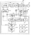
- FIG. 2 is a block diagram illustrating a more specific configuration example of the MCU 300 according to the first embodiment.
- FIG. 3 is a diagram schematically illustrating a configuration example of the inverter circuit 400 according to the first embodiment.
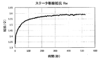
- FIG. 4A is a diagram illustrating an example of a temporal change in the winding resistance Rw under certain conditions.
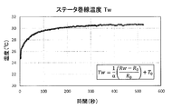
- FIG. 4B is a diagram illustrating an example of a temporal change in the winding temperature Tw under a certain condition.
- FIG. 1A is a diagram illustrating a schematic configuration of a motor module according to an exemplary embodiment 1 of the present disclosure.
- FIG. 1B is a diagram schematically illustrating an example of an internal configuration of the controller 300 according to the first embodiment.
- FIG. 2 is
- FIG. 5 is a flowchart illustrating an example (comparative example) of basic processing by the temperature estimator 350.
- FIG. 6A is a graph showing an example of a temporal change in the measured value and the estimated value of the winding temperature in a situation where the rotational speed of the rotor is constant and the torque changes with time.
- FIG. 6B is a graph showing an example of temporal changes in the measured value and the estimated value of the winding temperature in a situation where the torque is constant and the rotational speed of the rotor varies with time.
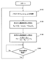
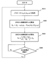
- FIG. 7 is a flowchart showing a basic flow of the temperature estimation process in the first embodiment.
- FIG. 8 is a flowchart illustrating another example of processing by the temperature estimator 350 according to the first embodiment.
- FIG. 9 is a flowchart illustrating an example of a process in which each of a group of parameters used for calculation of the provisional winding resistance Rw is averaged over time and used.
- FIG. 10 is a flowchart showing another modification of the first embodiment.
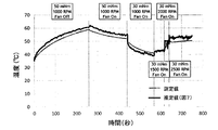
- FIG. 11A is a diagram showing an experimental result in which the winding temperature is estimated by the method shown in FIG. 5 under a situation where the load state changes.
- FIG. 11B is a diagram showing an experimental result in which the winding temperature is estimated by the method (difference method) shown in FIG. 7 under a situation where the load state changes.
- FIG. 12 is a flowchart illustrating an example of a temperature estimation process in the exemplary embodiment 2 of the present disclosure.
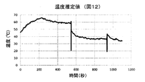
- FIG. 13 is a graph showing effects in the second embodiment.
- FIG. 11A is a diagram showing an experimental result in which the winding temperature is estimated by the method shown in FIG. 5 under a situation where the load state changes.
- FIG. 11B is a diagram showing an experimental result in
- FIG. 14 is a flowchart illustrating an example of processing combining the offset method and the difference method according to the second embodiment.
- FIG. 15A is a graph showing an example of a temporal change in winding temperature estimated using only the offset method shown in FIG.
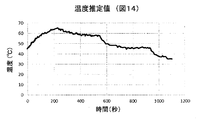
- FIG. 15B is a graph illustrating an example of a temporal change in winding temperature estimated by combining the offset method and the difference method illustrated in FIG. 14.
- FIG. 16 is a flowchart illustrating processing of a modification of the second embodiment.
- FIG. 17 is a flowchart illustrating an example of control executed by the motor module.
- FIG. 1A is a diagram illustrating a schematic configuration of a motor module in an exemplary embodiment of the present disclosure.
- the motor module includes a motor 100, a motor control circuit (motor control device) 200, a current sensor unit 500, and a rotor angle estimator 600.
- the motor 100 in this embodiment is an AC motor driven by three-phase AC.
- the motor 100 can be, for example, a permanent magnet synchronous motor.
- the motor 100 includes a rotor (rotor) and a stator (stator).
- the motor 100 is a permanent magnet synchronous motor (sometimes called a brushless DC motor)
- the rotor includes a permanent magnet
- the stator includes a plurality of windings (three-phase coils).
- an IPMSM Interior Permanent Magnet Synchronous Motor
- the motor 100 is not limited to the IPMSM.
- the current sensor unit 500 includes one or a plurality of sensors that monitor a current flowing through each of the plurality of windings.
- the current sensor unit 500 does not necessarily need to directly measure the current of each of the three-phase windings. For example, when the sum of three-phase currents is always zero, it is only necessary to measure only two-phase currents of the three-phase currents. The remaining one-phase current can be obtained by calculation. For this reason, even when only the two-phase current is measured, the current flowing through each winding can be monitored.
- the rotor angle estimator 600 obtains the angular position of the rotor in the motor 100 by measurement or calculation, and generates a rotor position signal indicating the angular position.
- the “angular position” of the rotor means a rotation angle (electrical angle, unit is degrees or radians) from the reference state of the rotor.
- the rotor angle estimator 600 may be implemented in one example by a sensor that measures the angular position of the rotor (eg, a hall element, resolver, or rotary encoder).
- the rotor angle estimator 600 is not limited to a sensor, and can also be realized by software executed by the motor control circuit 200. In this specification, “estimation” of the rotor angle by the rotor angle estimator 600 includes not only obtaining the rotor angle by calculation but also measuring using a sensor.
- the motor control circuit 200 is connected to the motor 100.
- the motor control circuit 200 controls the rotation of the rotor by applying a voltage to a plurality of windings in the stator according to a control algorithm such as a known field oriented control (FOC) algorithm.
- the motor control circuit 200 in this embodiment includes an inverter circuit 400 and a controller 300.
- Inverter circuit 400 applies a three-phase AC voltage to a plurality of windings in the stator of motor 100 in accordance with an instruction from controller 300.
- the controller 300 controls the inverter circuit 400 according to a control algorithm such as an FOC algorithm. Thereby, a desired three-phase AC voltage is applied to the plurality of windings in the stator of the motor 100.
- the controller 300 includes a temperature estimator 350 that repeats the process of estimating the electrical resistance and temperature of a plurality of windings in the stator of the motor 100.
- the electrical resistance of the plurality of windings means not the electrical resistance of each of the plurality of windings but the entire electrical resistance of the plurality of windings.
- FIG. 1B is a diagram schematically illustrating an example of the internal configuration of the controller 300.
- the controller 300 is realized by a microcontroller unit (MCU).
- the rotor angle estimator 330 and the temperature estimator 350 may be realized by software executed by the MCU. That is, the motor control circuit 200 includes a temperature estimator 350 that repeats the process of estimating the electrical resistance and temperature of a plurality of windings.
- the controller 300 is an MCU.
- the controller (MCU) 300 includes a CPU (Central Processing Unit) 360, a ROM (Read Only Memory) 370, and a RAM (Random Access Memory) 380.
- CPU Central Processing Unit
- ROM Read Only Memory
- RAM Random Access Memory
- the ROM 370 is a non-volatile memory and stores various software (computer programs) for controlling the motor 100.
- the RAM 380 is a volatile memory, and is a work memory used when the CPU 360 executes a program.
- the RAM 380 is also a storage medium that stores various parameters generated by the CPU 360 during the calculation process.
- the program used in this embodiment defines a known field-oriented control (FOC) algorithm and a temperature estimation algorithm described later. FOC is also called vector control, and is used to control a three-phase AC motor such as a permanent magnet synchronous motor.
- FOC field-oriented control
- the temperature estimator 350 is realized by software executed by the MCU 300, but may be realized by hardware (circuit) having an equivalent function.
- the temperature estimator 350 may be configured as a single device. In that case, the temperature estimator 350 is referred to as a “temperature estimation device”. Specific processing by the temperature estimator 350 will be described later.
- the rotor angle estimator 600 may also be realized by individual hardware (sensor or circuit).
- FIG. 2 is a block diagram showing a more specific configuration example of the MCU 300 in the present embodiment.
- the MCU 300 in the present embodiment controls the motor 100 according to the FOC algorithm.
- FIG. 2 shows a plurality of functional blocks used for controlling the motor 100.
- the MCU 300 in the present embodiment estimates the winding resistance and winding temperature of the motor 100 while controlling the motor 100. The estimation of the winding resistance and the winding temperature is performed by the temperature estimator 350.
- the MCU 300 includes an A / D converter 310 and a PWM driver 340 in addition to the above-described CPU 360, ROM 370, and RAM 380 as hardware.
- Other components (functional blocks) of the MCU 300 illustrated in FIG. 2 are realized by the CPU 360 executing software stored in the ROM 370.
- some or all of the components realized by software may be realized by hardware (circuit).
- some or all of the components realized by hardware may be realized by software.
- the PWM driver 340 and the AD converter 310 may be circuits provided outside the MCU 300.
- FIG. 3 is a diagram schematically illustrating a configuration example of the inverter circuit 400.
- the inverter circuit 400 in the present embodiment has a circuit configuration of a three-phase voltage source inverter.
- the inverter circuit 400 is a bridge circuit including six switching elements Sa, Sa ′, Sb, Sb ′, Sc, and Sc ′.
- Each switching element may be realized by a transistor such as an IGBT (Insulated-gate Bipolar Transistor) or a MOSFET (Metal Oxide Semiconductor Field-Effect Transistor).
- the gate of each switching element is connected to the PWM driver 340 in the MCU 300.
- the control signal (PWM pulse signal) output from the PWM driver 340 switches the conduction (on) / non-conduction (off) state of each switching element.
- the MCU 300 supplies three-phase alternating current to the motor 100 by controlling the conduction timing of each switching element.
- the three phases are expressed as phase a, phase b, and phase c.
- the number of pole pairs is 1, and three-phase windings in the motor 100 are schematically shown as three coils. However, this is only an example. There are various ways of winding the windings of each phase in an actual motor, and the number of pole pairs is not limited to 1, and may be 2 or more.
- the current flowing through the windings (coils) of each phase in the stator of the motor 100 is detected by the current sensor unit 500.
- the current sensor unit 500 can be, for example, a sensor using a Hall element that magnetically detects current in a non-contact manner in the vicinity of a line connected to the winding of each phase.
- the current sensor unit 500 is a sensor including a plurality of shunt resistors connected between the switching elements Sa ′, Sb ′, Sc ′ on the lower side of the inverter circuit 400 and the ground (GND). obtain.
- the current of each phase can be obtained from the voltage drop of the shunt resistor.
- the current sensor unit 500 does not have to measure all three-phase currents, and it is sufficient that at least two-phase currents can be detected.
- the current sensor unit 500 sends a signal indicating the detected current value of each phase to the MCU 300.
- the AD converter 310 in the MCU 300 converts the analog signals indicating the currents Ia, Ib, and Ic of each phase received from the current sensor unit 500 into digital signals and outputs the digital signals.
- the Clarke conversion module 320 performs coordinate conversion (Clark conversion) on the currents Ia, Ib, and Ic, and outputs signals indicating the ⁇ -axis component current I ⁇ and the ⁇ -axis component current I ⁇ .
- the ⁇ axis coincides with the phase a axis
- the ⁇ axis is an axis whose phase is advanced by 90 degrees from the ⁇ axis in terms of electrical angle.
- the Park conversion module 322 converts the currents I ⁇ and I ⁇ into currents Id and Iq expressed in a coordinate system that rotates together with the permanent magnet in the rotor of the motor 100 (Park conversion).
- the d-axis is an axis in the main direction of the magnetic flux generated by the permanent magnet in the rotor
- the q-axis is an axis whose phase is advanced by 90 degrees in electrical angle from the d-axis.
- the rotor angle estimator 600 estimates the rotational position of the rotor (rotor angle ⁇ e) using a known sensorless position detection technique.
- the rotor angle estimator 600 determines the rotor angle ⁇ e based on, for example, the induced voltage of each phase winding.
- a signal (rotor position signal) indicating the rotor angle ⁇ e determined by the rotor angle estimator 600 is sent to the Park conversion module 322 and the rotor speed estimator 331.
- the rotor speed estimator 331 calculates the rotor speed from the amount of change per unit time of the rotor angle ⁇ e.
- “Rotor speed” means the electrical angular speed ⁇ e (unit: rad / s) of the rotor.
- the Park conversion module 322 converts the currents I ⁇ and I ⁇ into currents Id and Iq based on the rotor position signal. As described above, the d-axis current Id and the q-axis current Iq are calculated based on the plurality of currents monitored by the current sensor unit 500 and the rotor position signal generated by the rotor angle estimator 600.
- Signals indicating the d-axis current Id and the q-axis current Iq calculated by the Park conversion module 322 are compared with the d-axis current command value Id * and the q-axis current command value Iq * , respectively. Then, signals indicating deviations (Id * ⁇ Id) and (Iq * ⁇ Iq) are input to the PI controller 333.
- the PI controller 333 performs PI control and determines voltage command values Vd * and Vq * that eliminate the deviation from the signals indicating the deviations (Id * ⁇ Id) and (Iq * ⁇ Iq).
- the current command values Id * and Iq * are determined by the PI controller 332.
- PI controller 333 based on the deviation ( ⁇ e * - ⁇ e) of the calculated rotor speed .omega.e and the speed command value .omega.e * by the rotor speed estimator 331, a current command value Id *, to determine the Iq *.
- the PI controller 332 performs PI control and determines current command values Id * and Iq * that eliminate the deviation ( ⁇ e * ⁇ e). Note that the PI controllers 332 and 333 may determine each command value by other control such as PID control or P control instead of the PI control.
- the inverse Park conversion module 334 converts the voltage command values Vd * and Vq * into voltage command values V ⁇ * and V ⁇ * in the stationary coordinate system.
- the space vector (SV) generator 335 performs space vector modulation on the basis of the voltage command values V ⁇ * and V ⁇ * , so that the ratio of conduction time per cycle of each switching element in the inverter circuit 400 (ON time). Called ratio).
- the PWM driver 340 outputs a control signal (PWM pulse signal) for switching on / off of each switching element of the inverter circuit 400 based on the determined on-time ratio.
- the above series of operations is repeatedly executed at a relatively short cycle (for example, a cycle of about 100 microseconds ( ⁇ s)).
- the rotor can rotate at a rotational speed that substantially matches the speed command value ⁇ e * .
- the configuration illustrated in FIG. 2 is merely an example, and the technology of the present disclosure is not limited to the configuration in FIG.
- the control signal of the inverter circuit 400 may be generated by another method such as a triangular wave comparison method instead of the space vector modulation.
- the MCU 300 in this embodiment further includes a temperature estimator 350 that estimates the winding temperature.
- the temperature estimator 350 includes a winding resistance estimation module 352 and a winding temperature estimation module 354.
- the winding resistance estimation module 352 estimates the winding resistance based on an expression that defines a relationship between a group of parameters used for controlling the motor 100 and the winding resistance.
- the winding temperature estimation module 354 estimates the winding temperature from the winding resistance based on the relationship between the winding resistance and the winding temperature.
- FIG. 4A and 4B show an example of the relationship between the winding resistance Rw and the winding temperature Tw in the stator.
- FIG. 4A is a diagram illustrating an example of a temporal change in the winding resistance Rw under certain conditions.
- FIG. 4B is a diagram illustrating an example of a temporal change in the winding temperature Tw under the same conditions.
- T0 represents a reference temperature (for example, room temperature)
- R0 represents a winding resistance at the reference temperature.
- ⁇ is a constant depending on the winding material, and is 0.004041 / K when the winding material is copper, for example.
- the winding temperature estimation module 354 in the present embodiment calculates the winding temperature Tw from the estimated winding resistance Rw using the equation (1).
- the temperature estimator 350 uses an equation that defines a relationship between a group of parameters used for controlling the motor 100 and the winding resistance.
- the group of parameters includes parameters indicative of voltage, current, and rotor speed (electrical angular speed).
- An expression defining a relationship between a group of parameters used for controlling the motor and the winding resistance can be, for example, the following expression (2).
- the temperature estimator 350 estimates the temporary electrical resistance each time based on the following equation (2).
- Rw is the electrical resistance of the winding
- Vq is the q-axis voltage
- ⁇ e is the electrical angular velocity of the rotor
- Id is the d-axis current
- Iq is the q-axis current
- Ld is the d-axis inductance of a plurality of windings
- ⁇ e is the rotor Is the number of magnetic flux linkages in the winding by the magnetic flux generated by the permanent magnet.
- Expression (2) is an expression in which the term of time differentiation is ignored in the following voltage equation (3) in the permanent magnet synchronous motor.
- the group of parameters used is a set of Vq, Id, Iq, and ⁇ e.
- the group of parameters includes the mechanical angular velocity ⁇ of the rotor.
- the mechanical angular velocity ⁇ can be estimated by the rotor angle estimator 600.
- the constant Ke is a known value obtained from prior measurements or motor specifications.
- the group of parameters used is a set of Vd, Id, Iq, and ⁇ e.
- Vd and Vq voltage command values Vd * and Vq * determined by the MCU 300 according to the FOC algorithm can be used.
- the parameters Id and Iq are currents Id and Iq calculated by the Park conversion module 322.
- the parameter ⁇ e is the electrical angular velocity ⁇ e calculated by the rotor speed estimator 331. These groups of parameters can be stored in RAM 380 as they are generated.
- the temperature estimator 350 acquires necessary parameters from the RAM 380 and uses them when estimating the winding resistance.
- Equation (5) the winding resistance is estimated mainly using Equation (5).
- the formula used is not limited to formula (5), but may be other formulas such as formula (4).
- FIG. 5 is a flowchart showing an example (comparative example) of basic processing by the temperature estimator 350.
- the temperature estimator 350 acquires parameters Vq, Id, Iq, and ⁇ e from the RAM 380.
- the winding resistance Rw is calculated based on Expression (5).
- the winding temperature Tw is calculated based on the equation (1).
- the process waits until a predetermined time (for example, 1 second) elapses.
- the temperature estimator 350 repeats the calculation (estimation) of the winding resistance Rw and the winding temperature Tw every predetermined time.
- the winding temperature Tw can be estimated by a relatively simple calculation. In a steady state where the load state of the motor 100 does not change, the winding temperature can be estimated with high accuracy by the processing shown in FIG.
- the process shown in FIG. 5 requires a countermeasure because the error increases when the load state of the motor 100 changes.
- the “load state” means an operation state determined by a combination of the rotational speed and torque of the rotor. Torque is determined by a combination of d-axis current and q-axis current. Therefore, it can be said that the “load state” is an operation state determined by a combination of the rotational speed of the rotor, the d-axis current, and the q-axis current.
- FIGS. 6A and 6B the problem that the temperature estimation error increases due to a change in the load state will be described with reference to FIGS. 6A and 6B.
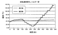
- FIG. 6A shows an example of changes over time in the measured value and estimated value of the winding temperature under the condition that the rotational speed of the rotor is constant and the torque changes over time.
- FIG. 6B shows an example of the temporal change of the measured value and the estimated value of the winding temperature under the situation where the torque is constant and the rotational speed of the rotor fluctuates with time.
- the measured value is the temperature of the winding measured using a temperature sensor.
- the estimated value is a temperature calculated by the method shown in FIG.
- the winding temperature estimated from the winding resistance Rw calculated using Equation (5) greatly deviates from the actual temperature.
- the main reason why such a divergence occurs is that the control parameter of the motor 100 changes greatly with the change of the load state, and the error in the expression ignoring the time differential term such as Expression (5) becomes large. it is conceivable that.
- the temperature estimator 350 in this embodiment repeats the process (cycle) for estimating the electrical resistance and temperature of a plurality of windings. Each process includes the following steps (1) to (4).
- the electrical resistance is estimated by adding the integrated value of the calculated resistance difference to the estimated initial value of the electrical resistance.
- the resistance difference exceeding the threshold value is excluded from the integrated value.
- FIG. 7 is a flowchart showing a basic flow of temperature estimation processing in the present embodiment.
- the temperature estimator 350 in the present embodiment estimates the winding temperature every predetermined time (for example, 1 second) by repeatedly executing the following processing. That is, the process of the temperature estimator 350 includes the steps described below.
- Step S210 The temperature estimator 350 acquires the parameters Vq, Id, Iq, and ⁇ e from the RAM 380.
- the parameter Vq is the same as the voltage command value Vq * shown in FIG.
- Each parameter may be a value at that time, but may be, for example, a value obtained by averaging the values of each parameter calculated between the previous temperature estimation and the current temperature estimation. By performing averaging, noise included in the calculation result can be reduced. An example of processing when averaging is described later.
- Step S220 The temperature estimator 350 calculates a temporary winding resistance Rw based on the equation (5).
- the temperature estimator 350 may use another equation such as equation (4) instead of equation (5).
- Step S240 The temperature estimator 350 determines whether or not the resistance difference ⁇ Rw exceeds a preset threshold value. When ⁇ Rw exceeds the threshold value, the process proceeds to step S250. If ⁇ Rw does not exceed the threshold value, the process proceeds to step S260.
- Step S250 The temperature estimator 350 sets ⁇ Rw to 0 and proceeds to step S260.
- Step S260 The temperature estimator 350 determines a value (Rw0 + ⁇ Rw) obtained by adding the integrated value ⁇ Rw of the resistance difference ⁇ Rw so far to the initial value Rw0 as the current Rw.
- the initial value Rw0 can be, for example, Rw calculated based on the formula (5) during the first processing.
- Rw calculated by the calculation of Rw0 + ⁇ Rw is processed as an estimated value of the current winding resistance.
- Step S270 The temperature estimator 350 calculates (estimates) the winding temperature Tw from the Rw estimated in step S260 based on the equation (1).
- Step S280 The temperature estimator 350 waits until a predetermined time elapses, and returns to step S210 after the predetermined time elapses.
- the processing of this embodiment is different from the processing shown in FIG. 5 in that Rw calculated based on Expression (5) is not used as an estimated value of the winding resistance as it is.
- the value obtained by adding the difference ⁇ Rw between the previously estimated Rw and the currently calculated Rw to the previously estimated Rw is the estimated value of the winding resistance.
- the same value as the previously estimated Rw is processed as the estimated value of the current winding resistance.
- the reason for such processing is that when ⁇ Rw is large, the load state is likely to have changed suddenly, and it is considered that the reliability of the value of Rw calculated based on Equation (5) is low. .
- the temperature estimator 350 can suppress the influence of fluctuations in the load state and estimate the temperature more accurately.
- a method of obtaining the electrical resistance of the winding by integrating ⁇ Rw as in the present embodiment may be referred to as a differential method in this specification.
- the MCU 300 detects a change in the load state based on a comparison result between ⁇ Rw and the threshold value.
- the MCU 300 may detect a change in the load state by another method.
- the MCU 300 may detect a change in load condition based on a time change of at least one parameter that determines the load condition, such as current and rotor speed.
- the resistance difference ⁇ Rw calculated when the change in the load state is detected is excluded from the integrated value.
- the processing of the temperature estimator 350 calculates a resistance difference calculated when the difference between the current value of the q-axis current Iq or the rotor speed ⁇ e and the previous value exceeds a threshold value, as an integrated value.
- FIG. 8 is a flowchart showing another example of processing by the temperature estimator 350 of the present embodiment.
- the flowchart shown in FIG. 8 differs from the flowchart shown in FIG. 7 only in that steps S230 and S240 are replaced with steps S230 'and S240', respectively.
- the temperature estimator 350 calculates differences ⁇ Rw, ⁇ Iq, ⁇ e between the current value and the previous value for each of Rw, Iq, ⁇ e.
- the temperature estimator 350 determines whether at least one of ⁇ Rw, ⁇ Iq, and ⁇ e exceeds the respective threshold value.
- step S250 temperature estimator 350 sets ⁇ Rw to 0 and proceeds to step S260. If all of ⁇ Rw, ⁇ Iq, and ⁇ e do not exceed the respective threshold values, the temperature estimator 350 proceeds to step S260.
- the subsequent operation is the same as the operation shown in FIG.
- a change in the load state is detected in consideration of not only ⁇ Rw but also the magnitudes of ⁇ Iq and ⁇ e. For this reason, even if ⁇ Rw is below the threshold, if ⁇ Iq or ⁇ e is large, that ⁇ Rw is not added to the previous estimated value of resistance. Such an operation further improves the accuracy of temperature estimation.
- the temperature estimator 350 can detect a change in load state based on at least one of a group of parameters used to calculate the provisional winding resistance Rw. When the temperature estimator 350 detects a change in the load state, the temperature estimator 350 can suppress the error by excluding the resistance difference ⁇ Rw from the integrated value.
- FIG. 9 is a flowchart showing an example of processing in which each of a group of parameters used for calculating the temporary winding resistance Rw is averaged over time.
- a cycle in which the winding temperature is estimated is a first cycle T1
- a cycle in which a group of parameters is calculated is a second cycle T2.
- the first period T1 is longer than the second period T2.
- the temperature estimator 350 calculates an average value of each parameter over the first period, and calculates a temporary electrical resistance Rw using the average value of each parameter.
- the second cycle T2 is a cycle in which each parameter is calculated according to the FOC algorithm, and may be a short time, for example, about 100 microseconds.
- the first period T1 can be, for example, about 10,000 times (about 1 second) of the second period T2. Since the winding temperature does not change so rapidly in time, it can be calculated at a frequency lower than the calculation period of each parameter in order to reduce the amount of calculation.
- the first period T1 can be set to about 10 milliseconds to 5 seconds, for example.
- the second period T2 can be set to about 20 to 500 microseconds, for example.
- the periods T1 and T2 are not limited to these numerical ranges.
- the value of each parameter calculated in the second period T2 is recorded in the RAM 380 every time it is calculated.
- Each time temperature estimation process in the present modification includes steps S310 to S390 shown in FIG.
- the temperature estimator 350 acquires the values of the parameters Vq, Id, Iq, and ⁇ e recorded for each second period T2 from the RAM 380 (step S310).
- the first period T1 is 10,000 times the second period T2
- the number of values of each parameter is 10,000.
- the temperature estimator 350 calculates the average value of each parameter (step S320). For example, when the temperature estimation is performed once every time each parameter is calculated 10,000 times, the temperature estimator 350 averages the values of each parameter for 10,000 times.
- the temperature estimator 350 calculates a temporary winding resistance Rw based on the equation (5) using the average value of each parameter (step S330). Subsequent steps S340 to S390 are the same as steps S230 to S280 shown in FIG. 7, respectively. Note that the “first period T1” in step S390 of FIG. 9 is the same as the “predetermined time” in step S280 of FIG.
- the temporary winding resistance Rw is calculated using a value obtained by averaging each parameter over the first period.
- noise can be reduced and a signal noise ratio (SN ratio) can be improved.
- a change in the load state is detected based on the magnitude of ⁇ Rw in steps S340 and S350.
- the present invention is not limited to this example.
- a change in load state may be detected based on at least one of ⁇ Rw, ⁇ Iq, and ⁇ e.
- FIG. 10 is a flowchart showing another modification of the present embodiment.
- the process shown in FIG. 10 differs from the process shown in FIG. 7 in that steps S410 and S420 are added after step S220.
- the other points are the same as the processing shown in FIG.
- the temperature estimator 350 determines whether or not the load state is similar to the reference state based on a group of parameters in each process of estimating the electrical resistance of the winding.
- the temperature estimator 350 determines (estimates) the calculated temporary winding resistance Rw as the current winding resistance Rw.
- the temperature estimator 350 updates the initial value Rw0 of the winding resistance with the current value of the temporary electrical resistance Rw. This update operation is referred to as “reset” in this specification.
- the temperature estimator 350 determines whether the load state is similar to the reference state based on the values of the torque T and the rotor speed ⁇ e. Instead of the torque T, determination may be made based on other parameters such as the value of the q-axis current Iq. In the example of FIG. 10, the temperature estimator 350 determines whether the torque T matches the reference value Tref and the rotor speed ⁇ e matches the reference value ⁇ ref (step S410).
- “match” means that the difference is sufficiently small. For example, if the difference is smaller than a certain threshold value, it is determined that they match (or are similar).
- the temperature estimator 350 determines the calculated temporary winding resistance Rw as the current winding resistance. Furthermore, the temperature estimator 350 updates the initial value Rw0 with the temporary winding resistance value (step S420). In the subsequent processing, the winding resistance and the winding temperature are estimated using the updated initial value Rw0.
- the step of estimating the electrical resistance of the winding includes the step S410 of determining whether the load state is similar to the reference state based on the group of parameters, and the load state. Includes a step S420 of updating the initial value of the electrical resistance with the value of the temporary electrical resistance, using the calculated temporary electrical resistance as the estimated value of the current electrical resistance when the value is similar to the reference state. .
- the resistance difference ⁇ Rw is added to the initial value Rw0 of the winding resistance in each process, errors are likely to accumulate. Therefore, as in the example shown in FIG. 10, when the load state is similar to the reference state, it is effective to reset the initial value with the value of the resistance Rw at that time. By the reset operation, noise accumulation can be suppressed and temperature estimation can be performed more accurately. Note that the reset operation shown in FIG. 10 is not limited to the operation shown in FIG. 7, and may be combined with other operations such as FIG. 8 or FIG.
- the method for estimating the temperature of the plurality of windings in the stator of the motor includes the step of repeating the process of estimating the electrical resistance and temperature of the plurality of windings.
- the process includes the following steps (1) to (5).
- Temporary electricity for a plurality of windings based on an equation defining the relationship between electrical resistance and a group of parameters including voltage, current and rotor speed used to control the rotation of the rotor. Calculating resistance.
- a step of estimating the electrical resistance by adding the calculated integrated value of the resistance difference to the estimated initial value of the electrical resistance.
- the resistance difference calculated when a change in the load state is detected is excluded from the integrated value.
- the temperature of the stator winding can be estimated with high accuracy even when the load state of the motor changes.
- the temperature estimator 350 in the present embodiment estimates the electrical resistance of a plurality of windings in the stator based on the following formula in each processing.
- f (Iq, ⁇ e) is a function of Iq and ⁇ e.
- the winding resistance is calculated using Equation (6) instead of or in addition to the difference method in the first embodiment.
- An offset term f (Iq, ⁇ e) that is not on the right side of Equation (5) is added to the right side of Equation (6).
- this offset term that depends on the q-axis current Iq and the electrical angular velocity ⁇ e, errors due to fluctuations in the load state can be suppressed.
- a method of estimating the winding resistance using an expression in which an offset term is introduced as in the present embodiment may be referred to as an offset method (Offset Method).
- the parameter ⁇ is determined from the following equation (7).
- C1, C2, C3, k1, k2, k3, and k4 are constants determined by experiments or the like. By setting these constants to appropriate values, the accuracy of the offset term can be increased.
- FIG. 12 is a flowchart showing an example of temperature estimation processing in the present embodiment.
- the temperature estimation process in the present embodiment includes the processes of steps S610 to S640 shown in FIG.
- step S610 the temperature estimator 350 acquires parameters Vq, Id, Iq, and ⁇ e from the RAM 380.
- step S620 temperature estimator 350 calculates winding resistance Rw based on equation (6) (step S620).
- step S630 the temperature estimator 350 calculates the winding temperature Tw based on the equation (1) as in the first embodiment.
- step S640 temperature estimator 350 waits until a predetermined time (corresponding to the first period described above) elapses, and executes step S610 again after the elapse of the time. With the above processing, temperature estimation can be performed more accurately even when the load state changes.
- FIG. 13 is a graph showing effects in the present embodiment.
- FIG. 13 shows an example of temporal changes in the estimated value and measured value of the winding temperature.
- the estimated value is the value of the winding temperature estimated by the method shown in FIG. 12, and the measured value is the temperature measured by the temperature sensor.
- the error is generally within 15%. Compared with the result of FIG. 11A, it can be seen that the error can be greatly reduced by the offset method in the present embodiment.
- FIG. 14 is a flowchart showing an example in which the offset method and the difference method are combined.
- the process in FIG. 14 is the same as the process shown in FIG. 7 except for step S720.
- Step S220 in FIG. 7 is replaced with step S720.
- step S720 temperature estimator 350 calculates temporary winding resistance Rw based on equation (6) instead of equation (5).
- the processing shown in FIG. 14 in addition to the effect of the difference method in the first embodiment, the effect of the offset method in the present embodiment can be obtained. As a result, the error can be further reduced.
- FIG. 15A and 15B show the effect of the temperature estimation method shown in FIG.
- FIG. 15A shows an example of the temporal change of the winding temperature estimated using only the offset method shown in FIG.
- FIG. 15B shows an example of a temporal change in winding temperature estimated by combining the offset method and the difference method shown in FIG. It was confirmed that by combining the offset method and the difference method, the error at the moment when the load state changes is greatly reduced.
- FIG. 16 is a flowchart showing a modification of the present embodiment.
- the temperature estimation process in this modification includes the processes of steps S810 to S910 shown in FIG. Steps S810 and S820 are the same as steps S310 and S320 shown in FIG. 9, respectively.
- the temperature estimator 350 acquires each parameter (Vq, Id, Iq, ⁇ e) recorded every second period T2 from the RAM 380, and calculates an average value of each parameter.
- step S830 temperature estimator 350 calculates temporary winding resistance Rw from equation (6) using the average value of each parameter.
- step S840 temperature estimator 350 determines whether or not the load state is similar to the standard state by comparing torque T with reference value Tref and comparing rotor speed ⁇ e with reference value ⁇ eref. If the load state is similar to the reference state, the temperature estimator 350 proceeds to step S850, determines the temporary winding resistance Rw as the current Rw, and updates the initial value Rw0 with the current Rw. The temperature estimator 350 proceeds to step S900 after step S850. When the load state is not similar to the reference state, the temperature estimator 350 performs the operations of steps S860, S870, S880, S890, S900, and S910. The operations in steps S860, S870, S880, S890, S900, and S910 are the same as the operations in steps S230 ', S240', S250, S260, S270, and S280 shown in FIG.
- the effects of parameter averaging, reset operation, and detection of changes in load state based on time changes of a plurality of parameters can be obtained. For this reason, the MCU 300 can estimate the winding temperature more accurately.
- FIG. 17 is a flowchart showing an example of a control method executed by the motor module.
- the control method includes the processes of steps S960 to S990 shown in FIG.
- step S960 the motor control circuit 200 controls the motor 100 according to the FOC algorithm.
- the temperature estimator 350 performs a process of estimating the stator winding temperature Tw by any of the methods described above.
- step S980 the MCU 300 in the motor control circuit 200 determines whether or not the estimated temperature Tw exceeds the threshold value Tth. If the temperature Tw exceeds the threshold value Tth, the MCU 300 proceeds to step S990 and decreases the rotor speed of the motor 100.
- the MCU 300 stops the motor 100 completely or sets the rotor speed to a lower value. More specifically, the MCU 300 reduces the rotor speed of the motor 100 by adjusting control signals supplied to the plurality of switching elements in the inverter circuit 400. If the estimated temperature Tw is equal to or lower than the threshold Tth, the MCU 300 returns to step S960.
- the threshold value Tth can be set to the maximum allowable temperature in the specification of the motor 100, for example.
- the motor 100 is stopped or decelerated at a high temperature, so that the reliability of the system can be improved.
- the motor module according to the embodiment of the present disclosure is suitably used for a movable body such as a UAV (Unmanned Aerial Vehicle, so-called drone), an automatic guided vehicle (AGV), or a robot, or an arbitrary electric device such as an axial fan. Can be done. Since the temperature can be accurately estimated without using a temperature sensor, it is possible to perform intelligent control according to the estimated temperature using a control circuit such as an MCU alone. As an example, the control circuit can transmit the temperature information of the device to an external server computer by communication, and the server computer can store the temperature information and use it for various purposes.
- the technology of the present disclosure can be applied to an application for estimating the temperature of a stator winding in an AC motor such as a permanent magnet synchronous motor.
- SYMBOLS 100 Electric motor, 200 ... Motor control circuit (motor control apparatus), 300 ... Controller (MCU), 310 ... AD converter, 320 ... Clarke conversion module, 322 ... Park conversion module, 331 ... Rotor speed estimator, 332 ... PI controller (current command value determination), 333 ... PI controller (voltage command value determination) 334 ... Inverse Park conversion module, 335 ... SV generator, 340 ... PWM driver, 350 ... Temperature estimator (temperature estimation device), 352 ... Winding resistance estimation module, 354 Winding temperature estimation module, 360 ... CPU, 370 ... ROM, 380 ... RAM, 400 ... inverter circuit, 500 ... current sensor unit, 600 ... rotor angle estimator
Landscapes
- Engineering & Computer Science (AREA)
- Power Engineering (AREA)
- Physics & Mathematics (AREA)
- General Physics & Mathematics (AREA)
- Control Of Ac Motors In General (AREA)
- Control Of Electric Motors In General (AREA)
Abstract
【課題】 モータの負荷状態が変化した場合における巻線温度の推定誤差を低減する。 【解決手段】 温度推定装置は、モータのステータにおける巻線の電気抵抗および温度を推定する処理を繰り返す。前記処理は、電気抵抗と、ロータの回転制御に用いられる一群のパラメータとの間の関係を規定する式に基づいて、巻線の仮の電気抵抗を計算し、仮の電気抵抗と前回推定した電気抵抗との抵抗差を計算し、計算した抵抗差の積算値を、電気抵抗の初期値に加算することにより、今回の電気抵抗を推定する。負荷状態の変化が検出されたときに計算された抵抗差は、前記積算値から除外される。
Description
本願は、電気モータにおけるステータ巻線の温度を推定する技術に関する。
ステータに複数の巻線を有する電気モータ(以下、単に「モータ」と称する。)の運転に伴ってステータ巻線から発生する熱は、モータを構成する材料の損傷および特性の変化を引き起こし得る。このため、モータの運転中にステータ巻線の温度(以下、「巻線温度」と称することがある。)を知ることは重要である。
ステータ巻線の温度は、種々の方法によって知ることができる。例えば、巻線の近傍に温度センサを配置し、当該温度センサを用いて巻線温度を直接測定する方法がある。温度センサには、例えば、熱電対または測温抵抗体(Resistive Temperature Device:RTD)などが用いられ得る。温度センサを用いる方法では、巻線の近傍に温度センサを配置することが困難な場合があり、また、コストの増加を招くという課題がある。
温度センサを用いずに、ステータ巻線の電気抵抗(以下、「巻線抵抗」と称することがある。)から巻線温度を推定することも可能である。巻線温度は、巻線抵抗の関数で表すことができるため、巻線抵抗から巻線温度を推定することができる。
巻線抵抗を求める方法には、大別して3つの方法がある。第1の方法は、測定器によって巻線抵抗を直接測定する方法である。しかし、巻線抵抗を直接測定するためには、モータを停止させる必要がある。このため、運転中に巻線温度を推定することができない。
第2の方法は、モータの運転中に、直流(DC)または交流(AC)の信号を注入し、当該信号から巻線抵抗を測定する方法である。第2の方法では、モータを制御するための信号に巻線抵抗を測定するための信号が混入する。このため、モータの動作を妨げる可能性がある。
第3の方法は、モータの電圧方程式などの関係式を利用して、モータの制御に用いられる各種のパラメータから、巻線温度を推定する方法である。第3の方法の例は、例えば特許文献1から3に開示されている。特許文献1から3の方法によれば、モータの運転中に巻線温度を推定することができると考えられる。
本開示は、モータの負荷状態が変化した場合における巻線温度の推定誤差を低減できる新規な温度推定技術を提供する。
本開示の例示的な実施形態における巻線温度推定方法は、電気モータのステータにおける複数の巻線の温度を推定するための方法である。前記複数の巻線の電気抵抗および温度を推定する処理を繰り返すステップを含む。前記処理は、電気抵抗と、前記ロータの回転の制御に用いられる、電圧、電流、およびロータ速度を含む一群のパラメータとの間の関係を規定する式に基づいて、前記複数の巻線の仮の電気抵抗を計算するステップと、前記仮の電気抵抗と前回推定した電気抵抗との抵抗差を計算するステップと、前記一群のパラメータに基づいて、負荷状態の変化を検出するステップと、計算された前記抵抗差の積算値を、推定された前記電気抵抗の初期値に加算することにより、前記電気抵抗を推定するステップと、推定された前記電気抵抗に基づいて、前記巻線の温度を推定するステップと、を含む。前記電気抵抗を推定するステップにおいては、これまでに計算された前記抵抗差のうち、前記負荷状態の変化が検出されたときに計算された抵抗差は、前記積算値から除外される。
上記の包括的または具体的な態様は、装置、システム、方法、集積回路、コンピュータプログラム、または記録媒体によって実現され得る。あるいは、装置、システム、方法、集積回路、コンピュータプログラム、および記録媒体の任意の組み合わせによっても実現され得る。
本開示の実施形態によれば、モータの負荷状態が変化した場合における巻線温度の推定誤差を低減することができる。
以下、本開示の例示的な実施形態を説明する。ただし、必要以上に詳細な説明は省略する場合がある。例えば、既によく知られた事項の詳細説明や実質的に同一の構成に対する重複する説明を省略する場合がある。これは、以下の説明が不必要に冗長になることを避け、当業者の理解を容易にするためである。なお、発明者は、当業者が本開示を十分に理解するために添付図面および以下の説明を提供するのであって、これらによって特許請求の範囲に記載の主題を限定することを意図するものではない。以下の説明においては、同一または類似する構成要素には、同一の参照符号を付している。
(実施形態1)
図1Aは、本開示の例示的な実施形態におけるモータモジュールの概略構成を示す図である。このモータモジュールは、モータ100と、モータ制御回路(モータ制御装置)200と、電流センサユニット500と、ロータ角度推定器600とを備える。
図1Aは、本開示の例示的な実施形態におけるモータモジュールの概略構成を示す図である。このモータモジュールは、モータ100と、モータ制御回路(モータ制御装置)200と、電流センサユニット500と、ロータ角度推定器600とを備える。
本実施形態におけるモータ100は、三相交流によって駆動される交流モータである。モータ100は、例えば、永久磁石同期モータであり得る。モータ100は、ロータ(回転子)とステータ(固定子)とを備える。モータ100が永久磁石同期モータ(ブラシレスDCモータと呼ばれることもある。)である場合、ロータは永久磁石を備え、ステータは複数の巻線(3相コイル)を備える。以下の説明では、主に、永久磁石がロータの内部に埋め込まれ、磁気的な突極性をもつIPMSM(Interior Permanent Magnet Synchronous Motor)を想定する。しかし、モータ100はIPMSMに限定されない。
電流センサユニット500は、複数の巻線のそれぞれを流れる電流をモニタする1つまたは複数のセンサを含む。電流センサユニット500は、必ずしも三相の巻線のそれぞれの電流を直接測定する必要はない。例えば、三相の電流の和が常にゼロになる場合には、三相の電流のうちの二相の電流のみを測定できればよい。残りの一相の電流は計算によって求めることができる。このため、二相の電流のみを測定する場合であっても、各巻線を流れる電流をモニタすることができる。
ロータ角度推定器600は、モータ100におけるロータの角度位置を測定または計算によって求め、当該角度位置を示すロータ位置信号を生成する。ロータの「角度位置」とは、ロータの基準状態からの回転角度(電気角であり、単位は、度またはラジアン)を意味する。ロータ角度推定器600は、ある例では、ロータの角度位置を測定するセンサ(例えば、ホール素子、レゾルバ、またはロータリエンコーダ)によって実現され得る。ロータ角度推定器600は、センサに限らず、モータ制御回路200が実行するソフトウェアによっても実現され得る。本明細書において、ロータ角度推定器600によるロータ角度の「推定」には、ロータ角度を計算によって求めることに加えて、センサを用いて測定することも含まれる。
モータ制御回路200は、モータ100に接続されている。モータ制御回路200は、例えば公知のフィールドオリエンテッドコントロール(FOC)アルゴリズムなどの制御アルゴリズムに従ってステータにおける複数の巻線に電圧を印加することにより、ロータの回転を制御する。本実施形態におけるモータ制御回路200は、インバータ回路400と、コントローラ300とを備える。インバータ回路400は、コントローラ300からの指示に従い、モータ100のステータにおける複数の巻線に三相交流電圧を印加する。コントローラ300は、FOCアルゴリズムなどの制御アルゴリズムに従ってインバータ回路400を制御する。これにより、モータ100のステータにおける複数の巻線に所望の三相交流電圧が印加される。
コントローラ300は、モータ100のステータにおける複数の巻線の電気抵抗および温度を推定する処理を繰り返す温度推定器350を備える。ここで、「複数の巻線の電気抵抗」とは、複数の巻線のそれぞれの電気抵抗ではなく、複数の巻線の全体の電気抵抗を意味する。
図1Bは、コントローラ300の内部構成の例を模式的に示す図である。図1Bの例では、コントローラ300は、マイクロコントローラユニット(MCU)によって実現されている。ロータ角度推定器330および温度推定器350は、MCUが実行するソフトウェアによって実現され得る。すなわち、モータ制御回路200は、複数の巻線の電気抵抗および温度を推定する処理を繰り返す温度推定器350を備える。
以下、コントローラ300がMCUであるものとして説明する。コントローラ(MCU)300は、CPU(Central Processing Unit)360と、ROM(Read Only Memory)370と、RAM(Random Access Memory)380とを備える。
ROM370は、不揮発性メモリであり、モータ100を制御するための各種ソフトウェア(コンピュータプログラム)を格納する。RAM380は、揮発性メモリであり、CPU360がプログラムを実行する際に利用されるワークメモリである。RAM380は、CPU360が計算の過程で生成する各種のパラメータを格納する記憶媒体でもある。本実施形態において用いられるプログラムは、公知のフィールドオリエンテッドコントロール(FOC)アルゴリズムと、後述する温度推定アルゴリズムとを規定する。FOCは、ベクトル制御とも呼ばれ、永久磁石同期モータなどの三相交流モータを制御するために用いられる。
本実施形態では、温度推定器350は、MCU300が実行するソフトウェアによって実現されるが、同等の機能を有するハードウェア(回路)によって実現されてもよい。温度推定器350は、単独の装置としても構成され得る。その場合には、温度推定器350を「温度推定装置」と称する。温度推定器350による具体的な処理については後述する。ロータ角度推定器600についても、個別のハードウェア(センサまたは回路)によって実現されていてもよい。
図2は、本実施形態におけるMCU300のより具体的な構成例を示すブロック図である。本実施形態におけるMCU300は、FOCアルゴリズムに従ってモータ100を制御する。図2には、モータ100の制御に使用される複数の機能ブロックが示されている。特に、本実施形態におけるMCU300は、モータ100を制御しながら、モータ100の巻線抵抗および巻線温度を推定する。巻線抵抗および巻線温度の推定は、温度推定器350によって行われる。
MCU300は、ハードウェアとして、前述のCPU360、ROM370、およびRAM380の他に、A-Dコンバータ310と、PWMドライバ340とを備えている。図2に示されているMCU300の他の構成要素(機能ブロック)は、CPU360がROM370に格納されたソフトウェアを実行することによって実現される。本実施形態においてソフトウェアによって実現される構成要素の一部または全部が、ハードウェア(回路)によって実現されてもよい。逆に、本実施形態においてハードウェアによって実現される構成要素の一部または全部が、ソフトウェアによって実現されてもよい。PWMドライバ340およびA-Dコンバータ310は、MCU300の外部に設けられた回路であってもよい。
図3は、インバータ回路400の構成例を模式的に示す図である。本実施形態におけるインバータ回路400は、三相電圧形インバータの回路構成を備える。インバータ回路400は、6個のスイッチング素子Sa、Sa’、Sb、Sb’、Sc、Sc’を備えたブリッジ回路である。各スイッチング素子は、例えばIGBT(Insulated-gate bipolar transistor)またはMOSFET(Metal Oxide Semiconductor Field-Effect Transistor)などのトランジスタによって実現され得る。各スイッチング素子のゲートは、MCU300におけるPWMドライバ340に接続されている。PWMドライバ340から出力される制御信号(PWMパルス信号)により、各スイッチング素子の導通(オン)/非導通(オフ)の状態が切り替えられる。MCU300は、各スイッチング素子の導通のタイミングを制御することにより、モータ100に三相交流を供給する。なお、本明細書では、3つの相を、相a、相b、相cと表現する。図3では、わかり易さのため、極対数を1として、モータ100における3つの相の巻線が3つのコイルとして模式的に示されている。しかし、これは例示にすぎない。実際のモータにおける各相の巻線の巻き方は多様であり、極対数も1に限らず、2以上であり得る。
再び図2を参照する。モータ100のステータにおける各相の巻線(コイル)を流れる電流は、電流センサユニット500によって検出される。電流センサユニット500は、例えば、各相の巻線に繋がるラインの近傍において、非接触で磁気的に電流を検出するホール素子を用いたセンサであり得る。他の例では、電流センサユニット500は、インバータ回路400の下側のスイッチング素子Sa’、Sb’、Sc’とグラウンド(GND)との間に接続された複数のシャント抵抗器を含むセンサであり得る。シャント抵抗器の電圧降下から各相の電流を求めることができる。なお、前述のように、電流センサユニット500は、三相の全ての電流を測定する必要はなく、このうちの少なくとも二相の電流を検出できればよい。電流センサユニット500は、検出した各相の電流値を示す信号をMCU300に送る。
MCU300におけるA-Dコンバータ310は、電流センサユニット500から受け取った各相の電流Ia、Ib、Icを示すアナログ信号を、デジタル信号に変換して出力する。Clarke変換モジュール320は、電流Ia、Ib、Icを座標変換(Clarke変換)して、α軸成分の電流Iαおよびβ軸成分の電流Iβを示す信号を出力する。ここで、α軸は相aの軸に一致し、β軸はα軸から電気角で90度位相が進んだ軸である。次に、Park変換モジュール322は、電流Iα、Iβを、モータ100のロータにおける永久磁石と共に回転する座標系で表した電流Id、Iqに変換する(Park変換)。周知のように、d軸はロータにおける永久磁石が作る磁束の主方向の軸であり、q軸はd軸から電気角で90度位相が進んだ軸である。
Park変換を行うためには、ロータの回転位置(電気角)の情報が必要である。ロータの回転位置の情報は、ロータ角度推定器600から得られる。本実施形態におけるロータ角度推定器600は、公知のセンサレス位置検出技術を用いて、ロータの回転位置(ロータ角度θe)を推定する。ロータ角度推定器600は、例えば、各相の巻線の誘起電圧に基づいて、ロータ角度θeを決定する。ロータ角度推定器600によって決定されたロータ角度θeを示す信号(ロータ位置信号)は、Park変換モジュール322およびロータ速度推定器331に送られる。ロータ速度推定器331は、ロータ角度θeの単位時間あたりの変化量から、ロータ速度を算出する。「ロータ速度」は、ロータの電気角速度ωe(単位はrad/s)を意味する。Park変換モジュール322は、ロータ位置信号に基づいて、電流Iα、Iβを、電流Id、Iqに変換する。このように、d軸電流Idおよびq軸電流Iqは、電流センサユニット500によってモニタされた複数の電流およびロータ角度推定器600が生成するロータ位置信号に基づいて計算される。
Park変換モジュール322によって計算されたd軸電流Idおよびq軸電流Iqを示す信号は、d軸電流の指令値Id*およびq軸電流の指令値Iq*とそれぞれ比較される。そして、偏差(Id*-Id)および(Iq*-Iq)を示す信号が、PIコントローラ333に入力される。PIコントローラ333は、PI制御を行い、偏差(Id*-Id)および(Iq*-Iq)を示す信号から、偏差をなくすような電圧指令値Vd*、Vq*を決定する。ここで、電流指令値Id*、Iq*は、PIコントローラ332によって決定される。PIコントローラ333は、ロータ速度推定器331によって計算されたロータ速度ωeと速度指令値ωe*との偏差(ωe*-ωe)に基づいて、電流指令値Id*、Iq*を決定する。PIコントローラ332は、PI制御を行い、偏差(ωe*-ωe)をなくすような電流指令値Id*、Iq*を決定する。なお、PIコントローラ332、333は、PI制御に代えて、例えばPID制御またはP制御などの他の制御によって各指令値を決定してもよい。
PIコントローラ333によって電圧指令値Vd*、Vq*が決定されると、逆Park変換モジュール334は、電圧指令値Vd*、Vq*を、静止座標系における電圧指令値Vα*、Vβ*に変換する(逆Park変換)。次に、空間ベクトル(SV)ジェネレータ335は、電圧指令値Vα*、Vβ*に基づいて空間ベクトル変調を行うことにより、インバータ回路400における各スイッチング素子の1周期あたりの導通時間の比(オン時間比と称する。)を決定する。PWMドライバ340は、決定されたオン時間比に基づいて、インバータ回路400の各スイッチング素子のオン/オフを切り替えるための制御信号(PWMパルス信号)を出力する。
以上の一連の動作は、比較的短い周期(例えば、100マイクロ秒(μs)程度の周期)で繰り返し実行される。以上の制御により、ロータは、速度指令値ωe*にほぼ一致する回転速度で回転することができる。なお、図2に示す構成は、あくまでも一例であり、本開示の技術は図2の構成に限定されない。例えば、空間ベクトル変調に代えて三角波比較法などの他の方法によってインバータ回路400の制御信号を生成してもよい。
本実施形態におけるMCU300は、さらに、巻線温度を推定する温度推定器350を備えている。温度推定器350は、巻線抵抗推定モジュール352と、巻線温度推定モジュール354とを備えている。巻線抵抗推定モジュール352は、後述するように、モータ100の制御に用いられる一群のパラメータと、巻線抵抗との間の関係を規定する式に基づいて、巻線抵抗を推定する。巻線温度推定モジュール354は、巻線抵抗と巻線温度との関係に基づいて、巻線抵抗から巻線温度を推定する。
図4Aおよび図4Bは、ステータにおける巻線抵抗Rwと巻線温度Twとの関係の一例を示している。図4Aは、ある条件下での巻線抵抗Rwの時間変化の一例を示す図である。図4Bは、同じ条件下での巻線温度Twの時間変化の一例を示す図である。巻線抵抗Rwと、巻線温度Twとの間には、近似的に以下の式(1)に示される関係がある。

ここで、T0は基準温度(例えば室温)を表し、R0は基準温度における巻線抵抗を表している。αは、巻線の材料に依存する定数であり、巻線の材料が例えば銅の場合、0.004041/Kである。本実施形態における巻線温度推定モジュール354は、式(1)を用いて、推定された巻線抵抗Rwから、巻線温度Twを計算する。
次に、温度推定器350による巻線抵抗を推定する処理の例を説明する。本実施形態における温度推定器350は、巻線抵抗を推定するために、モータ100の制御に用いられる一群のパラメータと、巻線抵抗との間の関係を規定する式を用いる。一群のパラメータは、電圧、電流、およびロータ速度(電気角速度)を示すパラメータを含む。モータの制御に用いられる一群のパラメータと、巻線抵抗との間の関係を規定する式は、例えば、以下の式(2)であり得る。例えば、温度推定器350は、以下の式(2)に基づいて各回の仮の電気抵抗を推定する。

ここで、Rwは巻線の電気抵抗、Vqはq軸電圧、ωeはロータの電気角速度、Idはd軸電流、Iqはq軸電流、Ldは複数の巻線のd軸インダクタンス、Ψeはロータにおける永久磁石が作る磁束による巻線における磁束鎖交数である。
式(2)は、永久磁石同期モータにおける以下の電圧方程式(3)において、時間微分の項を無視した式である。

式(3)において、記号「p」は、時間微分を表す。定常状態においては、pLd=0およびpLq=0と考えることができるため、式(2)が成立する。
式(2)を変形すると、以下の2つの式(4)、(5)が得られる。


ここで、磁束鎖交数ΨeおよびインダクタンスLd、Lqは、事前の測定またはモータの仕様から得られる既知の値である。本実施形態では、処理を簡単にするため、磁束鎖交数ΨeおよびインダクタンスLd、Lqの時間変化および温度依存性は無視する。式(4)、(5)から、パラメータVd、ωe、Id、Iqの組、または、パラメータVq、ωe、Id、Iqの組が得られれば、巻線抵抗Rwを推定できることがわかる。実際の計算では、式(4)および式(5)の一方を用いて、巻線抵抗Rwが計算され得る。d軸電流Idは、0に近い値に設定されることが多いため、典型的には、式(5)が用いられる。
式(5)を用いる場合、使用される一群のパラメータは、Vq、Id、Iq、ωeの組である。式(5)の第3項は、モータの逆起電力定数Keおよび機械角速度ω(=P×ωe、Pは極対数)を用いて、「-Ke×ω」と表すことができる。よって、式(5)を用いる場合、温度推定器350は、「-Ψe×ωe」の代わりに、「-Ke×ω」を計算してRwを求めてもよい。「-Ke×ω」の計算が行われる場合、一群のパラメータには、ロータの機械角速度ωも含まれる。機械角速度ωは、ロータ角度推定器600によって推定され得る。定数Keは、事前の測定またはモータの仕様から得られる既知の値である。一方、式(4)を用いる場合、使用される一群のパラメータは、Vd、Id、Iq、ωeの組である。
パラメータVd、Vqには、FOCアルゴリズムに従ってMCU300が決定した電圧指令値Vd*、Vq*が用いられ得る。パラメータId、Iqは、Park変換モジュール322によって計算された電流Id、Iqである。パラメータωeは、ロータ速度推定器331によって計算された電気角速度ωeである。これらの一群のパラメータは、生成される度に、RAM380に格納され得る。温度推定器350は、巻線抵抗の推定の際、必要なパラメータを、RAM380から取得して利用する。
以下、本実施形態における温度推定器350による処理の具体例を説明する。以下の説明では、主に式(5)を用いて巻線抵抗を推定する場合を想定する。ただし、使用される式は式(5)に限らず、式(4)などの他の式であってもよい。
図5は、温度推定器350による基本的な処理の例(比較例)を示すフローチャートである。温度推定器350は、ステップS110において、パラメータVq、Id、Iq、ωeをRAM380から取得する。ステップS120において、式(5)に基づいて、巻線抵抗Rwを算出する。ステップS130において、式(1)に基づいて、巻線温度Twを算出する。その後、ステップS140において、所定の時間(例えば1秒)が経過するまで待機し、当該時間が経過した場合、ステップS110に戻る。このように、温度推定器350は、所定時間ごとに、巻線抵抗Rwおよび巻線温度Twの算出(推定)を繰り返す。
図5に示す処理によれば、比較的簡単な計算によって巻線温度Twを推定することができる。モータ100の負荷状態が変化しない定常状態においては、図5に示す処理によって高い正確度で巻線温度を推定することができる。
しかし、本発明者らの検討によれば、図5に示す処理では、モータ100の負荷状態が変化した場合に誤差が大きくなるため、対策が必要であることが判明した。ここで、「負荷状態」とは、ロータの回転速度およびトルクの組み合わせによって定まる動作状態を意味する。トルクは、d軸電流およびq軸電流の組み合わせによって決まる。このため、「負荷状態」は、ロータの回転速度と、d軸電流およびq軸電流との組み合わせによって定まる動作状態であるともいえる。以下、負荷状態が変化することによって温度推定の誤差が大きくなる課題を、図6Aおよび図6Bを参照しながら説明する。
図6Aは、ロータの回転速度が一定で、トルクが時間的に変化する状況下での、巻線温度の測定値および推定値の時間変化の一例を示している。図6Bは、トルクが一定で、ロータの回転速度が時間的に変動する状況下での、巻線温度の測定値および推定値の時間変化の一例を示している。ここで、測定値は、温度センサを用いて測定した巻線の温度である。推定値は、図5に示す方法によって計算した温度である。図6Aおよび図6Bに示されるように、負荷状態が変化した場合、式(5)を用いて計算した巻線抵抗Rwから推定した巻線温度は、実際の温度から大きく乖離する。このような乖離が生じる主な理由は、負荷状態の変化に伴い、モータ100の制御パラメータが大きく変化し、式(5)のように時間微分項を無視した式では誤差が大きくなるからであると考えられる。
そこで、本実施形態では、図5の方法に代わる新たな温度推定方法が適用される。本実施形態における温度推定器350は、複数の巻線の電気抵抗および温度を推定する処理(サイクル)を繰り返す。各回の処理は、以下の(1)から(4)の工程(ステップ)を含む。
(1)複数の巻線の電気抵抗と、ロータの回転の制御に用いられる一群のパラメータ(電圧Vq、電流Id、Iq、およびロータ速度ωeを含む)との間の関係を規定する式に基づいて、複数の巻線の仮の電気抵抗Rwを計算する。
(2)仮の電気抵抗Rwと前回推定した電気抵抗との差(抵抗差)を計算する。
(3)計算された抵抗差の積算値を、推定された電気抵抗の初期値に加算することにより、電気抵抗を推定する。ここで、計算された抵抗差のうち、閾値を超える抵抗差は、前記積算値から除外される。
(4)推定された電気抵抗に基づいて、複数の巻線の温度を推定する。
以下、この温度推定方法の詳細を説明する。
以下、この温度推定方法の詳細を説明する。
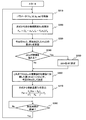
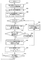
図7は、本実施形態における温度推定処理の基本的な流れを示すフローチャートである。本実施形態における温度推定器350は、以下の処理を繰り返し実行することにより、所定の時間(例えば1秒)ごとに巻線温度を推定する。すなわち、温度推定器350の処理は、以下に説明する各ステップを含む。
ステップS210:温度推定器350は、RAM380から、パラメータVq、Id、Iq、およびωeを取得する。パラメータVqは、図2に示す電圧指令値Vq*と同一である。各パラメータは、その時点での値であってもよいが、例えば前回の温度推定時から今回の温度推定までの間に計算された各パラメータの値を平均化した値であってもよい。平均化を行うことにより、計算結果に含まれるノイズを低減できる。平均化を行う場合の処理の例については、後述する。
ステップS220:温度推定器350は、式(5)に基づいて、仮の巻線抵抗Rwを計算する。温度推定器350は、式(5)に代えて、式(4)などの他の式を用いてもよい。
ステップS230:温度推定器350は、今回計算したRwと、前回決定(推定)したRwとの間の差ΔRw(抵抗差)を計算する。ここで、前回推定したRwは、式(5)に基づいて計算した値であるとは限らず、前回の処理において、最終的に決定した巻線抵抗Rwの推定値である。
ステップS240:温度推定器350は、抵抗差ΔRwが、予め設定された閾値を超えるか否かを判断する。ΔRwが当該閾値を超える場合、ステップS250に進む。ΔRwが当該閾値を超えない場合、ステップS260に進む。
ステップS250:温度推定器350は、ΔRwを0に設定して、ステップS260に進む。
ステップS260:温度推定器350は、これまでの抵抗差ΔRwの積算値ΣΔRwを初期値Rw0に加算した値(Rw0+ΣΔRw)を、今回のRwとして決定する。初期値Rw0は、例えば初回の処理時に、式(5)に基づいて計算したRwであり得る。Rw0+ΣΔRwの演算によって計算したRwが、今回の巻線抵抗の推定値として処理される。
ステップS270:温度推定器350は、式(1)に基づき、ステップS260において推定したRwから巻線温度Twを算出(推定)する。
ステップS280:温度推定器350は、所定時間が経過するまで待機し、所定時間が経過した後、ステップS210に戻る。
本実施形態の処理は、式(5)に基づいて計算されるRwをそのまま巻線抵抗の推定値とするのではない点で、図5に示す処理とは異なっている。本実施形態では、前回推定されたRwと今回計算したRwとの差ΔRwを、前回推定されたRwに加算した値が、巻線抵抗の推定値となる。ただし、抵抗差ΔRwがある閾値を超える場合には、ΔRw=0として処理される。すなわち、ΔRwが閾値を超える場合、そのΔRwは無視される。その結果、前回推定されたRwと同じ値が、今回の巻線抵抗の推定値として処理される。そのように処理される理由は、ΔRwが大きい場合、負荷状態が急に変化した可能性が高く、式(5)に基づいて計算されたRwの値の信頼性が低いと考えられるからである。このような処理により、温度推定器350は、負荷状態の変動の影響を抑制して、より正確に温度を推定できる。本実施形態のように、ΔRwを積算することによって巻線の電気抵抗を求める方法を、本明細書では差分法(Differential Method)と称することがある。
図7に示す例では、MCU300は、負荷状態の変化を、ΔRwと閾値との比較結果に基づいて検出している。しかし、MCU300は、負荷状態の変化を、他の方法によって検出してもよい。例えば、MCU300は、電流およびロータ速度のような、負荷状態を決める少なくとも1つのパラメータの時間変化に基づいて、負荷状態の変化を検出してもよい。負荷状態の変化が検出されたときに計算された抵抗差ΔRwは、積算値から除外される。一例として、温度推定器350の処理が、ΔRwに加えて、q軸電流Iqまたはロータ速度ωeの現在の値と前回の値との差が閾値を超えるときに計算された抵抗差を、積算値からさらに除外する処理を含む例を説明する。
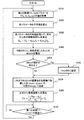
図8は、本実施形態の温度推定器350による処理の他の例を示すフローチャートである。図8に示すフローチャートは、図7に示すフローチャートと比べて、ステップS230およびS240が、それぞれステップS230’およびS240’に置き換わった点のみが異なる。温度推定器350は、ステップS230’において、Rw、Iq、ωeのそれぞれについて、今回の値と前回の値との差ΔRw、ΔIq、Δωeを算出する。そして、ステップS240’において、温度推定器350は、ΔRw、ΔIq、Δωeの少なくとも1つが、それぞれの閾値を超えるか否かを判定する。ΔRw、ΔIq、Δωeの少なくとも1つが、それぞれの閾値を超える場合には、ステップS250において、温度推定器350は、ΔRwを0に設定してステップS260に進む。温度推定器350は、ΔRw、ΔIq、Δωeの全てが、それぞれの閾値を超えない場合には、ステップS260に進む。以後の動作は、図7に示す動作と同じである。
図8に示される例では、ΔRwだけでなく、ΔIqおよびΔωeの大きさも考慮して、負荷状態の変化が検出される。このため、ΔRwが閾値を下回っていたとしても、ΔIqまたはΔωeが大きい場合には、そのΔRwは前回の抵抗の推定値に加算されない。このような動作により、温度推定の正確度がさらに向上する。
上記の例に限定されず、温度推定器350は、仮の巻線抵抗Rwを計算するために使用される一群のパラメータの少なくとも1つに基づいて負荷状態の変化を検出することができる。温度推定器350は、負荷状態の変化を検出した場合には、抵抗差ΔRwを積算値から除外することにより、誤差を抑制することができる。
次に、本実施形態による差分法の変形例を説明する。
図9は、仮の巻線抵抗Rwの計算に用いられる一群のパラメータのそれぞれを時間的に平均化して使用する処理の例を示すフローチャートである。ここで、巻線温度が推定される周期を第1の周期T1、一群のパラメータが計算される周期を第2の周期T2とする。第1の周期T1は、第2の周期T2よりも長い。温度推定器350は、第1の周期にわたって各パラメータの平均値を求め、各パラメータの平均値を用いて、仮の電気抵抗Rwを計算する。第2の周期T2は、本実施形態においては、FOCアルゴリズムに従って各パラメータが計算される周期であり、例えば100マイクロ秒程度の短い時間であり得る。これに対し、第1の周期T1は、例えば第2の周期T2の10000倍程度(1秒程度)であり得る。巻線温度は時間的にそれほど急には変化しないため、計算量を抑えるために、各パラメータの計算周期よりも低い頻度で計算され得る。第1の周期T1は、例えば、10ミリ秒から5秒程度に設定され得る。第2の周期T2は、例えば、20マイクロ秒から500マイクロ秒程度に設定され得る。ただし、周期T1およびT2は、これらの数値範囲に限定されない。
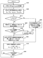
図9に示す例では、第2の周期T2で計算された各パラメータの値は、計算の都度、RAM380に記録される。本変形例における各回の温度推定処理は、図9に示されるステップS310~S390を含む。まず、温度推定器350は、RAM380から第2の周期T2ごとに記録されたパラメータVq、Id、Iq、ωeの値を取得する(ステップS310)。第1の周期T1が第2の周期T2の10000倍である場合、各パラメータの値の数は10000個である。温度推定器350は、各パラメータの平均値を算出する(ステップS320)。例えば、温度推定器350は、各パラメータが10000回計算される毎に温度推定を1回行う場合には、各パラメータの10000回分の値を平均化する。温度推定器350は、各パラメータの平均値を用いて、式(5)に基づき、仮の巻線抵抗Rwを算出する(ステップS330)。以降のステップS340からS390は、それぞれ、図7に示すステップS230からS280と同様である。なお、図9のステップS390における「第1の周期T1」は、図7のステップS280における「所定時間」と同じである。
図9に示す例では、各パラメータを第1の周期にわたって平均化した値を用いて仮の巻線抵抗Rwが計算される。これにより、ノイズを低減し、信号雑音比(SN比)を向上させることができる。
図9に示す例では、図7に示す例と同様に、ステップS340およびS350において、ΔRwの大きさに基づいて負荷状態の変化が検出される。この例に限定されず、例えば図8に示す例のように、ΔRw、ΔIq、Δωeの少なくとも1つの大きさに基づいて負荷状態の変化を検出してもよい。
図10は、本実施形態の他の変形例を示すフローチャートである。図10に示す処理は、ステップS220の後にステップS410およびS420が追加されている点で、図7に示す処理と異なる。それ以外の点は、図7に示す処理と同じである。図10の例では、温度推定器350は、巻線の電気抵抗を推定する各回の処理において、一群のパラメータに基づいて、負荷状態が基準の状態に類似しているか否かを決定する。温度推定器350は、負荷状態が当該基準の状態に類似しているとき、計算した仮の巻線抵抗Rwを、今回の巻線抵抗Rwとして決定(推定)する。さらに、温度推定器350は、巻線抵抗の初期値Rw0を、今回の仮の電気抵抗Rwの値で更新する。この更新動作を、本明細書では、「リセット」と称する。
より具体的には、温度推定器350は、負荷状態が基準の状態に類似しているか否かを、トルクTおよびロータ速度ωeの値に基づいて判断する。トルクTに代えて、例えばq軸電流Iqの値などの他のパラメータに基づいて判断してもよい。図10の例において、温度推定器350は、トルクTが参照値Trefに一致し、ロータ速度ωeが参照値ωrefに一致しているかを判断する(ステップS410)。ここで「一致」とは、差分が十分に小さいことを意味する。例えば差分がある閾値よりも小さければ、一致(または類似)していると判断される。温度推定器350は、トルクTおよびロータ速度ωeがそれぞれの参照値に類似していると判断した場合、計算した仮の巻線抵抗Rwを、今回の巻線抵抗として決定する。さらに、温度推定器350は、仮の巻線抵抗の値で初期値Rw0を更新する(ステップS420)。以後の処理では、更新された初期値Rw0を用いて、巻線抵抗および巻線温度が推定される。
以上のように、本変形例では、巻線の電気抵抗を推定するステップは、一群のパラメータに基づいて、負荷状態が基準の状態に類似しているか否かを決定するステップS410と、負荷状態が基準の状態に類似しているとき、計算された仮の電気抵抗を、今回の電気抵抗の推定値とし、電気抵抗の初期値を、仮の電気抵抗の値で更新するステップS420とを含む。
本実施形態における差分法では、毎回の処理において、巻線抵抗の初期値Rw0に抵抗差ΔRwが加算されていくため、誤差が蓄積され易い。このため、図10に示す例のように、負荷状態が基準の状態に類似しているときには、そのときの抵抗Rwの値で初期値をリセットすることが有効である。リセット動作により、ノイズの蓄積を抑制し、温度推定をさらに正確に行うことができる。なお、図10に示すリセット動作は、図7に示す動作に限らず、図8または図9などの他の動作と組み合わせてもよい。
次に、図11Aおよび図11Bを参照しながら、本実施形態の効果を説明する。
図11Aは、負荷状態が変化する状況下で、図5に示す方法(比較例)で巻線温度を推定した実験結果を示す図である。図11Bは、同じ状況下で、図7に示す方法(差分法)で巻線温度を推定した実験結果を示す図である。図11Aおよび図11Bには、温度センサを用いて巻線温度を測定した結果も示されている。本実験では、モータのトルク(単位:mNm)および単位時間当たりの回転数(単位:RPM)、並びにモータを冷却するファンのON/OFFを変化させながら、巻線温度を図5および図7の各方法で推定し、かつ、温度センサで測定した。図11Aからわかるように、図5に示す比較例の方法では、モータの負荷状態(トルクまたは回転速度)が変化すると、温度の推定値が測定値から大きく乖離する。これに対して、図7に示す差分法を用いた場合には、図11Bに示すように、測定値からの乖離が抑制されている。この結果から、本実施形態における差分法の有効性が確認できた。
以上のように、本実施形態におけるモータのステータにおける複数の巻線の温度を推定する方法は、複数の巻線の電気抵抗および温度を推定する処理を繰り返すステップを含む。当該処理は、以下の(1)から(5)のステップを含む。
(1)電気抵抗と、前記ロータの回転の制御に用いられる、電圧、電流、およびロータ速度を含む一群のパラメータとの間の関係を規定する式に基づいて、複数の巻線の仮の電気抵抗を計算するステップ。
(2)仮の電気抵抗と前回推定した電気抵抗との抵抗差を計算するステップ。
(3)一群のパラメータに基づいて、負荷状態の変化を検出するステップ。
(4)計算された抵抗差の積算値を、推定された前記電気抵抗の初期値に加算することにより、電気抵抗を推定するステップ。
ここで、計算された抵抗差のうち、負荷状態の変化が検出されたときに計算された抵抗差は、積算値から除外される。
(5)推定された電気抵抗に基づいて、複数の巻線の温度を推定するステップ。
(1)電気抵抗と、前記ロータの回転の制御に用いられる、電圧、電流、およびロータ速度を含む一群のパラメータとの間の関係を規定する式に基づいて、複数の巻線の仮の電気抵抗を計算するステップ。
(2)仮の電気抵抗と前回推定した電気抵抗との抵抗差を計算するステップ。
(3)一群のパラメータに基づいて、負荷状態の変化を検出するステップ。
(4)計算された抵抗差の積算値を、推定された前記電気抵抗の初期値に加算することにより、電気抵抗を推定するステップ。
ここで、計算された抵抗差のうち、負荷状態の変化が検出されたときに計算された抵抗差は、積算値から除外される。
(5)推定された電気抵抗に基づいて、複数の巻線の温度を推定するステップ。
以上の処理により、モータの負荷状態が変化した場合であっても、高い正確度でステータ巻線の温度を推定することができる。
(実施形態2) 次に、本開示の第2の実施形態を説明する。本実施形態におけるモータモジュールの構成は、実施形態1における構成と同様である。本実施形態では、巻線抵抗を推定する際に使用されるアルゴリズムが実施形態1とは異なっている。以下、実施形態1と異なる点を説明する。
本実施形態における温度推定器350は、各回の処理において、以下の式に基づいて、ステータにおける複数の巻線の電気抵抗を推定する。

ここで、f(Iq,ωe)は、Iqおよびωeの関数である。
本実施形態では、実施形態1における差分法に代えて、または差分法に加えて、式(6)を用いて巻線抵抗が算出される。式(6)の右辺には、式(5)の右辺にはないオフセット項f(Iq,ωe)が追加されている。q軸電流Iqおよび電気角速度ωeに依存するこのオフセット項を導入することにより、負荷状態の変動による誤差を抑制することができる。本明細書では、本実施形態のようにオフセット項を導入した式を用いて巻線抵抗を推定する方法を、オフセット法(Offset Method)と称することがある。
本発明者らの検討によれば、オフセット項f(Iq,ωe)は、α(ωe-ω0)のように表すことができる。ここで、αは、Iqおよびωeに依存するパラメータであり、ω0は、基準状態(例えば室温の状態)におけるロータの電気角速度である。パラメータαを適切に設定することにより、負荷の変動の影響を抑制することができる。
パラメータαは、より詳細には、以下の式(7)から決定される。

ここで、C1、C2、C3、k1、k2、k3、k4は、実験などによって決定される定数である。これらの定数を適切な値に設定することにより、オフセット項の正確度を高めることができる。
図12は、本実施形態における温度推定処理の例を示すフローチャートである。本実施形態における温度推定処理は、図12に示されるステップS610~S640の処理を含む。温度推定器350は、ステップS610において、パラメータVq、Id、Iq、ωeをRAM380から取得する。温度推定器350は、ステップS620において、式(6)に基づいて、巻線抵抗Rwを算出する(ステップS620)。温度推定器350は、ステップS630において、実施形態1と同様に、式(1)に基づいて、巻線温度Twを算出する。温度推定器350は、ステップS640において、所定時間(前述の第1の周期に相当)が経過するまで待機し、当該時間の経過後、再びステップS610を実行する。以上の処理により、負荷状態が変化した場合でも、温度推定をより正確に行うことができる。
図13は、本実施形態における効果を示すグラフである。図13は、巻線温度の推定値および測定値の時間変化の一例を示している。推定値は、図12に示す方法で推定した巻線温度の値であり、測定値は、温度センサで測定した温度である。図13からわかるように、誤差が概ね15%以内に収まっている。図11Aの結果と比較すれば、本実施形態のけるオフセット法により、誤差を大幅に低減できることがわかる。
このように、オフセット法によれば、巻線抵抗および巻線温度の推定の誤差を低減することができる。しかし、図13に示すように、負荷状態が変化する瞬間では、誤差が大きくなる。この誤差を抑制するためには、実施形態1で説明した差分法を利用すればよい。
図14は、オフセット法と差分法とを組み合わせた例を示すフローチャートである。図14の処理は、ステップS720を除き、図7に示す処理と同じである。図7におけるステップS220が、ステップS720に置換されている。ステップS720において、温度推定器350は、式(5)ではなく式(6)に基づいて、仮の巻線抵抗Rwを算出する。図14に示される処理により、実施形態1における差分法の効果に加えて、本実施形態におけるオフセット法の効果を得ることができる。その結果、誤差をさらに低減することができる。
図15Aおよび図15Bは、図14に示す温度推定方法の効果を示している。図15Aは、図12に示すオフセット法のみを用いて推定した巻線温度の時間変化の一例を示している。図15Bは、図14に示すオフセット法および差分法を組み合わせて推定した巻線温度の時間変化の一例を示している。オフセット法と差分法とを組み合わせることにより、負荷状態が変化した瞬間の誤差が大きく低減されることが確認された。
次に、本実施形態の変形例を説明する。本実施形態においても、実施形態1について説明した全ての変形例を適用できる。例えば、図8~10を参照しながら説明した変形例は、本実施形態においても適用できる。一例として、図8~10に示す変形例を組み合わせた例を説明する。
図16は、本実施形態の変形例を示すフローチャートである。本変形例における温度推定処理は、図16に示されるステップS810からS910の処理を含む。ステップS810およびS820は、それぞれ、図9に示すステップS310およびS320と同じである。温度推定器350は、第2の周期T2ごとに記録された各パラメータ(Vq、Id、Iq、ωe)をRAM380から取得し、各パラメータの平均値を算出する。ステップS830において、温度推定器350は、各パラメータの平均値を用いて、式(6)から仮の巻線抵抗Rwを算出する。ステップS840において、温度推定器350は、負荷状態が基準の状態に類似するか否かを、トルクTと参照値Trefとの比較、およびロータ速度ωeと参照値ωerefとの比較によって判断する。温度推定器350は、負荷状態が基準の状態に類似する場合、ステップS850に進み、仮の巻線抵抗Rwを今回のRwとして決定し、今回のRwで初期値Rw0を更新する。温度推定器350は、ステップS850の後、ステップS900に進む。負荷状態が基準の状態に類似しない場合、温度推定器350は、ステップS860、S870、S880、S890、S900、S910の動作を実行する。ステップS860、S870、S880、S890、S900、S910の動作は、図8に示すステップS230’、S240’、S250、S260、S270、S280の動作と同様であるため、説明を省略する。
図16に示す動作によれば、オフセット法および差分法による効果に加え、パラメータの平均化、リセット動作、および複数のパラメータの時間変化に基づく負荷状態の変化の検出の効果が得られる。このため、MCU300は、巻線温度をさらに正確に推定することができる。
次に、推定した巻線温度Twを利用した制御の例を説明する。
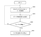
図17は、モータモジュールによって実行される制御方法の一例を示すフローチャートである。当該制御方法は、図17に示すステップS960からS990の処理を含む。ステップS960において、モータ制御回路200は、FOCアルゴリズムに従ってモータ100を制御する。この制御の具体例は、図2を参照しながら説明したとおりである。ステップS970において、温度推定器350は、上述したいずれかの方法で、ステータ巻線の温度Twを推定する処理を行う。モータ制御回路200におけるMCU300は、ステップS980において、推定した温度Twが閾値Tthを超えているか否かを判断する。MCU300は、温度Twが閾値Tthを超えている場合には、ステップS990に進み、モータ100のロータ速度を減少させる。例えば、MCU300は、モータ100を完全に停止させるか、ロータ速度をより低い値に設定する。より具体的には、MCU300は、インバータ回路400における複数のスイッチング素子に供給する制御信号を調整してモータ100のロータ速度を減少させる。MCU300は、推定した温度Twが閾値Tth以下である場合は、ステップS960に戻る。閾値Tthは、例えば、モータ100の仕様上、許容できる最大の温度に設定され得る。
以上の動作により、高温時にはモータ100が停止または減速されるため、システムの信頼性を向上させることができる。
本開示の実施形態によれば、温度センサを用いることなく、ステータ巻線の温度を高い正確度で推定する温度センサレスモータモジュールを実現できる。このため、温度センサを搭載することが困難な用途においても、好適に利用できる。本開示の実施形態におけるモータモジュールは、例えば、UAV(Unmanned Aerial Vehicle、所謂ドローン)、無人搬送車(AGV)、もしくはロボットといった移動体、または、軸流ファンなどの任意の電動機器に好適に利用され得る。温度センサを用いることなく温度を正確に推定できるため、例えばMCUなどの制御回路単独で、推定した温度に応じたインテリジェントな制御を行うことが可能である。一例として、制御回路が、通信によって外部のサーバコンピュータに機器の温度情報を送信し、サーバコンピュータが当該温度情報を蓄積して種々の目的に活用する、といった用途も可能である。
本開示の技術は、例えば永久磁石同期モータなどの交流モータにおけるステータ巻線の温度を推定する用途に適用できる。
100・・・電気モータ、200・・・モータ制御回路(モータ制御装置)、300・・・コントローラ(MCU)、310・・・A-Dコンバータ、
320・・・Clarke変換モジュール、322・・・Park変換モジュール、331・・・ロータ速度推定器、332・・・PIコントローラ(電流指令値決定)、333・・・PIコントローラ(電圧指令値決定)、334・・・逆Park変換モジュール、335・・・SVジェネレータ、340・・・PWMドライバ、350・・・温度推定器(温度推定装置)、352・・・巻線抵抗推定モジュール、354・・・巻線温度推定モジュール、360・・・CPU、370・・・ROM、380・・・RAM、400・・・インバータ回路、500・・・電流センサユニット、600・・・ロータ角度推定器
320・・・Clarke変換モジュール、322・・・Park変換モジュール、331・・・ロータ速度推定器、332・・・PIコントローラ(電流指令値決定)、333・・・PIコントローラ(電圧指令値決定)、334・・・逆Park変換モジュール、335・・・SVジェネレータ、340・・・PWMドライバ、350・・・温度推定器(温度推定装置)、352・・・巻線抵抗推定モジュール、354・・・巻線温度推定モジュール、360・・・CPU、370・・・ROM、380・・・RAM、400・・・インバータ回路、500・・・電流センサユニット、600・・・ロータ角度推定器
Claims (18)
- ロータおよびステータを有し、前記ステータは複数の巻線を有する、電気モータと、
前記複数の巻線のそれぞれを流れる電流をモニタする電流センサユニットと、
前記ロータの角度位置を示すロータ位置信号を生成するロータ角度推定器と、
前記電気モータに接続され、前記複数の巻線に電圧を印加することによって前記ロータの回転を制御するモータ制御回路と、を備え、
前記モータ制御回路は、前記複数の巻線の電気抵抗および温度を推定する処理を繰り返す温度推定器を備え、
前記処理は、
電気抵抗と、前記ロータの回転の制御に用いられる、電圧、電流、およびロータ速度を含む一群のパラメータとの間の関係を規定する式に基づいて、前記複数の巻線の仮の電気抵抗を計算するステップと、
前記仮の電気抵抗と前回推定した電気抵抗との抵抗差を計算するステップと、
計算された前記抵抗差の積算値を、推定された前記電気抵抗の初期値に加算することにより、前記電気抵抗を推定するステップであって、計算された前記抵抗差のうち、閾値を超える抵抗差は、前記積算値から除外される、ステップと、
推定された前記電気抵抗に基づいて、前記複数の巻線の温度を推定するステップと、を含む、モータモジュール。 - 計算された前記抵抗差のうち、電流またはロータ速度の現在の値と前回の値との差が閾値を超えるときに計算された前記抵抗差は、前記積算値からさらに除外される、請求項1に記載のモータモジュール。
- 前記電気モータは、永久磁石同期モータであり、
前記モータ制御回路は、フィールドオリエンテッドコントロールアルゴリズムに従って前記複数の巻線に電圧を印加することにより、前記ロータの回転を制御する、請求項1または2に記載のモータモジュール。 - 前記温度推定器は、
Rwを前記仮の電気抵抗、Vqをq軸電圧、ωeを前記ロータの電気角速度、Idをd軸電流、Iqをq軸電流、Ldを前記複数の巻線のd軸インダクタンス、Ψeを前記ロータからの磁束による前記複数の巻線における磁束鎖交数として、以下の式

- 前記温度推定器は、
Rwを前記仮の電気抵抗、Vqをq軸電圧、ωeを前記ロータの電気角速度、Idをd軸電流、Iqをq軸電流、Ldを前記複数の巻線のd軸インダクタンス、Ψeを前記ロータからの磁束による前記複数の巻線における磁束鎖交数、f(Iq,ωe)をIqおよびωeの関数として、以下の式

- 前記温度推定器は、αをIqおよびωeに依存するパラメータ、ω0を基準状態におけるロータの電気角速度として、以下の式

- Vqは、前記制御回路によって決定された電圧指令値であり、
IdおよびIqは、前記電流センサユニットによってモニタされた複数の電流および前記ロータ位置信号に基づいて計算される、請求項4から6のいずれかに記載のモータモジュール。 - 前記温度推定器は、推定された前記電気抵抗の前記初期値を、前記式に基づいて決定する、請求項1から7のいずれかに記載のモータモジュール。
- 前記モータ制御回路は、推定された前記温度が閾値を超えているとき、前記ロータ速度を減少させる、請求項1から8のいずれかに記載のモータモジュール。
- 前記電気抵抗を推定するステップは、
前記一群のパラメータに基づいて、負荷状態が基準の状態に類似しているか否かを決定するステップと、
前記負荷状態が前記基準の状態に類似しているとき、計算された前記仮の電気抵抗を、前記電気抵抗として推定し、推定された前記電気抵抗の初期値を、前記仮の電気抵抗の値で更新するステップと、を含む、請求項1から9のいずれかに記載のモータモジュール。 - 前記温度推定器は、
第1の周期で前記処理を繰り返し、前記第1の周期は、前記一群のパラメータが計算される第2の周期よりも長く、
前記第1の周期にわたって各パラメータの平均値を求め、
各パラメータの前記平均値を用いて、前記仮の電気抵抗を計算する、請求項1から10のいずれかに記載のモータモジュール。 - 電気モータを制御するモータ制御装置であって、
前記電気モータは、ロータおよびステータを有し、前記ステータは複数の巻線を有し、
前記モータ制御装置は、
前記複数の巻線に電圧を印加することによって前記ロータの回転を制御し、
前記複数の巻線の電気抵抗および温度を推定する処理を繰り返す温度推定器を備え、
前記処理は、
電気抵抗と、前記ロータの回転の制御に用いられる、電圧、電流、およびロータ速度を含む一群のパラメータとの間の関係を規定する式に基づいて、前記複数の巻線の仮の電気抵抗を計算するステップと、
前記仮の電気抵抗と前回推定した電気抵抗との抵抗差を計算するステップと、
計算された前記抵抗差の積算値を、推定された前記電気抵抗の初期値に加算することにより、前記電気抵抗を推定するステップであって、計算された前記抵抗差のうち、閾値を超える抵抗差は、前記積算値から除外される、ステップと、
推定された前記電気抵抗に基づいて、前記複数の巻線の温度を推定するステップと、を含む、モータ制御装置。 - 電気モータを制御するモータ制御装置において用いられる温度推定装置であって、
前記電気モータは、ロータおよびステータを有し、前記ステータは複数の巻線を有し、
前記モータ制御装置は、前記複数の巻線に電圧を印加することによって前記ロータの回転を制御し、
前記温度推定装置は、前記複数の巻線の電気抵抗および温度を推定する処理を繰り返し、
前記処理は、
電気抵抗と、前記ロータの回転の制御に用いられる、電圧、電流、およびロータ速度を含む一群のパラメータとの間の関係を規定する式に基づいて、前記複数の巻線の仮の電気抵抗を計算するステップと、
前記仮の電気抵抗と前回推定した電気抵抗との抵抗差を計算するステップと、
計算された前記抵抗差の積算値を、推定された前記電気抵抗の初期値に加算することにより、前記電気抵抗を推定するステップであって、計算された前記抵抗差のうち、閾値を超える抵抗差は、前記積算値から除外される、ステップと、
推定された前記電気抵抗に基づいて、前記複数の巻線の温度を推定するステップと、を含む、温度推定装置。 - 電気モータのステータにおける複数の巻線の温度を推定する方法であって、
前記複数の巻線の電気抵抗および温度を推定する処理を繰り返すステップを含み、
前記処理は、
電気抵抗と、前記ロータの回転の制御に用いられる、電圧、電流、およびロータ速度を含む一群のパラメータとの間の関係を規定する式に基づいて、前記複数の巻線の仮の電気抵抗を計算するステップと、
前記仮の電気抵抗と前回推定した電気抵抗との抵抗差を計算するステップと、
計算された前記抵抗差の積算値を、推定された前記電気抵抗の初期値に加算することにより、前記電気抵抗を推定するステップであって、計算された前記抵抗差のうち、閾値を超える抵抗差は、前記積算値から除外される、ステップと、
推定された前記電気抵抗に基づいて、前記複数の巻線の温度を推定するステップと、を含む、方法。 - ロータおよびステータを有し、前記ステータは複数の巻線を有する、電気モータと、
前記複数の巻線のそれぞれを流れる電流をモニタする電流センサユニットと、
前記ロータの角度位置を示すロータ位置信号を生成するロータ角度推定器と、
前記電気モータに接続され、前記複数の巻線に電圧を印加することによって前記ロータの回転を制御するモータ制御回路と、を備え、
前記モータ制御回路は、前記複数の巻線の電気抵抗および温度を推定する処理を繰り返す温度推定器を備え、
前記処理は、
電気抵抗と、前記ロータの回転の制御に用いられる、電圧、電流、およびロータ速度を含む一群のパラメータとの間の関係を規定する式に基づいて、前記複数の巻線の仮の電気抵抗を計算するステップと、
前記仮の電気抵抗と前回推定した電気抵抗との抵抗差を計算するステップと、
前記一群のパラメータに基づいて、負荷状態の変化を検出するステップと、
計算された前記抵抗差の積算値を、推定された前記電気抵抗の初期値に加算することにより、前記電気抵抗を推定するステップであって、計算された前記抵抗差のうち、前記負荷状態の変化が検出されたときに計算された抵抗差は、前記積算値から除外される、ステップと、
推定された前記電気抵抗に基づいて、前記複数の巻線の温度を推定するステップと、を含む、モータモジュール。 - 電気モータを制御するモータ制御装置であって、
前記電気モータは、ロータおよびステータを有し、前記ステータは複数の巻線を有し、
前記モータ制御装置は、
前記複数の巻線に電圧を印加することによって前記ロータの回転を制御し、
前記複数の巻線の電気抵抗および温度を推定する処理を繰り返す温度推定器を備え、
前記処理は、
電気抵抗と、前記ロータの回転の制御に用いられる、電圧、電流、およびロータ速度を含む一群のパラメータとの間の関係を規定する式に基づいて、前記複数の巻線の仮の電気抵抗を計算するステップと、
前記仮の電気抵抗と前回推定した電気抵抗との抵抗差を計算するステップと、
前記一群のパラメータに基づいて、負荷状態の変化を検出するステップと、
計算された前記抵抗差の積算値を、推定された前記電気抵抗の初期値に加算することにより、前記電気抵抗を推定するステップであって、計算された前記抵抗差のうち、前記負荷状態の変化が検出されたときに計算された抵抗差は、前記積算値から除外される、ステップと、
推定された前記電気抵抗に基づいて、前記複数の巻線の温度を推定するステップと、を含む、モータ制御装置。 - 電気モータを制御するモータ制御装置において用いられる温度推定装置であって、
前記電気モータは、ロータおよびステータを有し、前記ステータは複数の巻線を有し、
前記モータ制御装置は、前記複数の巻線に電圧を印加することによって前記ロータの回転を制御し、
前記温度推定装置は、前記複数の巻線の電気抵抗および温度を推定する処理を繰り返し、
前記処理は、
電気抵抗と、前記ロータの回転の制御に用いられる、電圧、電流、およびロータ速度を含む一群のパラメータとの間の関係を規定する式に基づいて、前記複数の巻線の仮の電気抵抗を計算するステップと、
前記仮の電気抵抗と前回推定した電気抵抗との抵抗差を計算するステップと、
前記一群のパラメータに基づいて、負荷状態の変化を検出するステップと、
計算された前記抵抗差の積算値を、推定された前記電気抵抗の初期値に加算することにより、前記電気抵抗を推定するステップであって、計算された前記抵抗差のうち、前記負荷状態の変化が検出されたときに計算された抵抗差は、前記積算値から除外される、ステップと、
推定された前記電気抵抗に基づいて、前記複数の巻線の温度を推定するステップと、を含む、温度推定装置。 - 電気モータのステータにおける複数の巻線の温度を推定する方法であって、
前記複数の巻線の電気抵抗および温度を推定する処理を繰り返すステップを含み、 前記処理は、 電気抵抗と、前記ロータの回転の制御に用いられる、電圧、電流、およびロータ速度を含む一群のパラメータとの間の関係を規定する式に基づいて、前記複数の巻線の仮の電気抵抗を計算するステップと、
前記仮の電気抵抗と前回推定した電気抵抗との抵抗差を計算するステップと、
前記一群のパラメータに基づいて、負荷状態の変化を検出するステップと、
計算された前記抵抗差の積算値を、推定された前記電気抵抗の初期値に加算することにより、前記電気抵抗を推定するステップであって、計算された前記抵抗差のうち、前記負荷状態の変化が検出されたときに計算された抵抗差は、前記積算値から除外される、ステップと、
推定された前記電気抵抗に基づいて、前記複数の巻線の温度を推定するステップと、を含む、方法。
Priority Applications (4)
| Application Number | Priority Date | Filing Date | Title |
|---|---|---|---|
| CN201780044802.4A CN109526244A (zh) | 2016-07-21 | 2017-07-14 | 马达模块、马达控制装置、温度估计装置以及温度估计方法 |
| EP17830967.0A EP3490138A4 (en) | 2016-07-21 | 2017-07-14 | MOTOR MODULE, MOTOR CONTROL DEVICE, TEMPERATURE ESTIMATION DEVICE AND METHOD |
| JP2018528531A JPWO2018016448A1 (ja) | 2016-07-21 | 2017-07-14 | モータモジュール、モータ制御装置、温度推定装置、および温度推定方法 |
| US16/251,269 US20190173413A1 (en) | 2016-07-21 | 2019-01-18 | Motor module, motor controller, temperature inferring device, and temperature inference method |
Applications Claiming Priority (2)
| Application Number | Priority Date | Filing Date | Title |
|---|---|---|---|
| JP2016143455 | 2016-07-21 | ||
| JP2016-143455 | 2016-07-21 |
Related Child Applications (1)
| Application Number | Title | Priority Date | Filing Date |
|---|---|---|---|
| US16/251,269 Continuation US20190173413A1 (en) | 2016-07-21 | 2019-01-18 | Motor module, motor controller, temperature inferring device, and temperature inference method |
Publications (1)
| Publication Number | Publication Date |
|---|---|
| WO2018016448A1 true WO2018016448A1 (ja) | 2018-01-25 |
Family
ID=60993187
Family Applications (1)
| Application Number | Title | Priority Date | Filing Date |
|---|---|---|---|
| PCT/JP2017/025799 Ceased WO2018016448A1 (ja) | 2016-07-21 | 2017-07-14 | モータモジュール、モータ制御装置、温度推定装置、および温度推定方法 |
Country Status (5)
| Country | Link |
|---|---|
| US (1) | US20190173413A1 (ja) |
| EP (1) | EP3490138A4 (ja) |
| JP (1) | JPWO2018016448A1 (ja) |
| CN (1) | CN109526244A (ja) |
| WO (1) | WO2018016448A1 (ja) |
Cited By (2)
| Publication number | Priority date | Publication date | Assignee | Title |
|---|---|---|---|---|
| US11165375B2 (en) | 2019-04-23 | 2021-11-02 | Accelerated Systems Inc. | Methods and systems for controlling electric motors |
| WO2025244506A1 (ko) * | 2024-05-22 | 2025-11-27 | 엘지이노텍 주식회사 | 모터 제어 장치 |
Families Citing this family (9)
| Publication number | Priority date | Publication date | Assignee | Title |
|---|---|---|---|---|
| EP3599715B1 (en) * | 2018-07-26 | 2022-08-24 | Siemens Gamesa Renewable Energy A/S | Assessing wind turbine generator rotor temperature |
| JP7388158B2 (ja) | 2019-11-29 | 2023-11-29 | オムロン株式会社 | 処理装置、及び巻線温度算出モデルの決定方法 |
| DE102020100175A1 (de) * | 2020-01-07 | 2021-07-08 | Ebm-Papst Mulfingen Gmbh & Co. Kg | Heizgebläsemotor |
| CN111277200B (zh) * | 2020-02-12 | 2021-10-22 | 杭州电子科技大学 | 一种电机绕组温度估计及保护方法 |
| JP6980068B1 (ja) * | 2020-09-02 | 2021-12-15 | 三菱電機株式会社 | 回転電機の制御装置 |
| WO2022244166A1 (ja) * | 2021-05-19 | 2022-11-24 | ファナック株式会社 | 温度推定装置及びコンバータシステム |
| CN113489383B (zh) * | 2021-07-01 | 2023-11-07 | 青岛海信日立空调系统有限公司 | 一种压缩机启动控制方法 |
| CN115078996B (zh) * | 2022-06-22 | 2024-11-08 | 徐州市华为工程机械有限公司 | 一种多组对比式微型马达负荷驱动绕组温度实验检测装置 |
| CN116252296A (zh) * | 2022-12-20 | 2023-06-13 | 合肥工业大学 | 一种考虑温度影响的协作机械臂关节模组补偿控制方法 |
Citations (6)
| Publication number | Priority date | Publication date | Assignee | Title |
|---|---|---|---|---|
| US20100194329A1 (en) * | 2009-01-30 | 2010-08-05 | Bin Lu | System and method for determining stator winding resistance in an ac motor using motor drives |
| JP2011015584A (ja) * | 2009-07-06 | 2011-01-20 | Toshiba Mach Co Ltd | モータ巻線焼損保護装置 |
| JP2012050261A (ja) * | 2010-08-27 | 2012-03-08 | Jtekt Corp | モータ制御装置およびこれを備える電動パワーステアリング装置 |
| JP2014011861A (ja) * | 2012-06-28 | 2014-01-20 | Mitsuba Corp | 温度推定装置、温度推定方法、および、制御装置 |
| WO2015022722A1 (ja) * | 2013-08-12 | 2015-02-19 | 三菱電機株式会社 | コイル温度推定方法およびモータ制御装置 |
| JP2015122857A (ja) * | 2013-12-24 | 2015-07-02 | 日産自動車株式会社 | 電動機の制御装置 |
Family Cites Families (2)
| Publication number | Priority date | Publication date | Assignee | Title |
|---|---|---|---|---|
| JP4501433B2 (ja) * | 2003-10-24 | 2010-07-14 | ダイキン工業株式会社 | Dcモータのコイル温度推定方法およびその装置 |
| US8604803B2 (en) * | 2006-05-19 | 2013-12-10 | Pratt & Whitney Canada Corp. | System and method for monitoring temperature inside electric machines |
-
2017
- 2017-07-14 CN CN201780044802.4A patent/CN109526244A/zh not_active Withdrawn
- 2017-07-14 WO PCT/JP2017/025799 patent/WO2018016448A1/ja not_active Ceased
- 2017-07-14 JP JP2018528531A patent/JPWO2018016448A1/ja not_active Withdrawn
- 2017-07-14 EP EP17830967.0A patent/EP3490138A4/en not_active Withdrawn
-
2019
- 2019-01-18 US US16/251,269 patent/US20190173413A1/en not_active Abandoned
Patent Citations (6)
| Publication number | Priority date | Publication date | Assignee | Title |
|---|---|---|---|---|
| US20100194329A1 (en) * | 2009-01-30 | 2010-08-05 | Bin Lu | System and method for determining stator winding resistance in an ac motor using motor drives |
| JP2011015584A (ja) * | 2009-07-06 | 2011-01-20 | Toshiba Mach Co Ltd | モータ巻線焼損保護装置 |
| JP2012050261A (ja) * | 2010-08-27 | 2012-03-08 | Jtekt Corp | モータ制御装置およびこれを備える電動パワーステアリング装置 |
| JP2014011861A (ja) * | 2012-06-28 | 2014-01-20 | Mitsuba Corp | 温度推定装置、温度推定方法、および、制御装置 |
| WO2015022722A1 (ja) * | 2013-08-12 | 2015-02-19 | 三菱電機株式会社 | コイル温度推定方法およびモータ制御装置 |
| JP2015122857A (ja) * | 2013-12-24 | 2015-07-02 | 日産自動車株式会社 | 電動機の制御装置 |
Non-Patent Citations (1)
| Title |
|---|
| See also references of EP3490138A4 * |
Cited By (2)
| Publication number | Priority date | Publication date | Assignee | Title |
|---|---|---|---|---|
| US11165375B2 (en) | 2019-04-23 | 2021-11-02 | Accelerated Systems Inc. | Methods and systems for controlling electric motors |
| WO2025244506A1 (ko) * | 2024-05-22 | 2025-11-27 | 엘지이노텍 주식회사 | 모터 제어 장치 |
Also Published As
| Publication number | Publication date |
|---|---|
| EP3490138A4 (en) | 2020-01-01 |
| EP3490138A1 (en) | 2019-05-29 |
| CN109526244A (zh) | 2019-03-26 |
| JPWO2018016448A1 (ja) | 2019-07-04 |
| US20190173413A1 (en) | 2019-06-06 |
Similar Documents
| Publication | Publication Date | Title |
|---|---|---|
| WO2018016448A1 (ja) | モータモジュール、モータ制御装置、温度推定装置、および温度推定方法 | |
| JP5223109B2 (ja) | 永久磁石形同期電動機の制御装置 | |
| JP2009142116A (ja) | 永久磁石モータの位置センサレス制御装置 | |
| TWI756423B (zh) | 油泵電動機用驅動設備與驅動控制方法 | |
| KR20130086730A (ko) | 전동기의 센서리스 제어 장치 및 방법 | |
| JP7058725B2 (ja) | 電動機制御装置 | |
| US12255558B2 (en) | Motor controller, motor system and method for controlling motor | |
| JP2013146155A (ja) | 巻線温度推定装置及び巻線温度推定方法 | |
| JP2009278760A (ja) | モータ制御装置及びモータ制御方法 | |
| JP2009290962A (ja) | 永久磁石形同期電動機の制御装置 | |
| US10666178B2 (en) | Motor control device and control method | |
| JP5332305B2 (ja) | 永久磁石形同期電動機の制御装置 | |
| JP5332301B2 (ja) | 永久磁石形同期電動機の制御装置 | |
| JP4781933B2 (ja) | 電動機の制御装置 | |
| JP5534991B2 (ja) | 同期電動機の制御装置 | |
| JP6508021B2 (ja) | モータ温度推定装置 | |
| JP2015192463A (ja) | モータ制御装置及び発電機制御装置 | |
| JP4735439B2 (ja) | 永久磁石式同期電動機の初期磁極位置推定装置 | |
| JP2010028981A (ja) | 同期モータの回転子位置推定方法および同期モータの制御装置 | |
| JP6497584B2 (ja) | 永久磁石形同期電動機の制御装置 | |
| JP2011010486A (ja) | 永久磁石同期機の制御装置 | |
| KR20100070221A (ko) | 센서리스 bldc 모터의 제어 방법 및 장치 | |
| WO2024181185A1 (ja) | 制御装置 | |
| JP2024176219A (ja) | 制御装置 | |
| JP2007082380A (ja) | 同期モータ制御装置 |
Legal Events
| Date | Code | Title | Description |
|---|---|---|---|
| 121 | Ep: the epo has been informed by wipo that ep was designated in this application |
Ref document number: 17830967 Country of ref document: EP Kind code of ref document: A1 |
|
| NENP | Non-entry into the national phase |
Ref country code: DE |
|
| ENP | Entry into the national phase |
Ref document number: 2018528531 Country of ref document: JP Kind code of ref document: A |
|
| ENP | Entry into the national phase |
Ref document number: 2017830967 Country of ref document: EP Effective date: 20190221 |