WO2018020536A1 - 空気調和機の室外機 - Google Patents
空気調和機の室外機 Download PDFInfo
- Publication number
- WO2018020536A1 WO2018020536A1 PCT/JP2016/071681 JP2016071681W WO2018020536A1 WO 2018020536 A1 WO2018020536 A1 WO 2018020536A1 JP 2016071681 W JP2016071681 W JP 2016071681W WO 2018020536 A1 WO2018020536 A1 WO 2018020536A1
- Authority
- WO
- WIPO (PCT)
- Prior art keywords
- bottom plate
- outdoor unit
- heat exchanger
- air conditioner
- conditioner according
- Prior art date
- Legal status (The legal status is an assumption and is not a legal conclusion. Google has not performed a legal analysis and makes no representation as to the accuracy of the status listed.)
- Ceased
Links
Images


Classifications
-
- F—MECHANICAL ENGINEERING; LIGHTING; HEATING; WEAPONS; BLASTING
- F24—HEATING; RANGES; VENTILATING
- F24F—AIR-CONDITIONING; AIR-HUMIDIFICATION; VENTILATION; USE OF AIR CURRENTS FOR SCREENING
- F24F1/00—Room units for air-conditioning, e.g. separate or self-contained units or units receiving primary air from a central station
- F24F1/06—Separate outdoor units, e.g. outdoor unit to be linked to a separate room comprising a compressor and a heat exchanger
- F24F1/14—Heat exchangers specially adapted for separate outdoor units
- F24F1/16—Arrangement or mounting thereof
-
- F—MECHANICAL ENGINEERING; LIGHTING; HEATING; WEAPONS; BLASTING
- F28—HEAT EXCHANGE IN GENERAL
- F28D—HEAT-EXCHANGE APPARATUS, NOT PROVIDED FOR IN ANOTHER SUBCLASS, IN WHICH THE HEAT-EXCHANGE MEDIA DO NOT COME INTO DIRECT CONTACT
- F28D1/00—Heat-exchange apparatus having stationary conduit assemblies for one heat-exchange medium only, the media being in contact with different sides of the conduit wall, in which the other heat-exchange medium is a large body of fluid, e.g. domestic or motor car radiators
- F28D1/02—Heat-exchange apparatus having stationary conduit assemblies for one heat-exchange medium only, the media being in contact with different sides of the conduit wall, in which the other heat-exchange medium is a large body of fluid, e.g. domestic or motor car radiators with heat-exchange conduits immersed in the body of fluid
- F28D1/04—Heat-exchange apparatus having stationary conduit assemblies for one heat-exchange medium only, the media being in contact with different sides of the conduit wall, in which the other heat-exchange medium is a large body of fluid, e.g. domestic or motor car radiators with heat-exchange conduits immersed in the body of fluid with tubular conduits
- F28D1/047—Heat-exchange apparatus having stationary conduit assemblies for one heat-exchange medium only, the media being in contact with different sides of the conduit wall, in which the other heat-exchange medium is a large body of fluid, e.g. domestic or motor car radiators with heat-exchange conduits immersed in the body of fluid with tubular conduits the conduits being bent, e.g. in a serpentine or zig-zag
- F28D1/0477—Heat-exchange apparatus having stationary conduit assemblies for one heat-exchange medium only, the media being in contact with different sides of the conduit wall, in which the other heat-exchange medium is a large body of fluid, e.g. domestic or motor car radiators with heat-exchange conduits immersed in the body of fluid with tubular conduits the conduits being bent, e.g. in a serpentine or zig-zag the conduits being bent in a serpentine or zig-zag
-
- F—MECHANICAL ENGINEERING; LIGHTING; HEATING; WEAPONS; BLASTING
- F28—HEAT EXCHANGE IN GENERAL
- F28F—DETAILS OF HEAT-EXCHANGE AND HEAT-TRANSFER APPARATUS, OF GENERAL APPLICATION
- F28F17/00—Removing ice or water from heat-exchange apparatus
- F28F17/005—Means for draining condensates from heat exchangers, e.g. from evaporators
-
- F—MECHANICAL ENGINEERING; LIGHTING; HEATING; WEAPONS; BLASTING
- F28—HEAT EXCHANGE IN GENERAL
- F28F—DETAILS OF HEAT-EXCHANGE AND HEAT-TRANSFER APPARATUS, OF GENERAL APPLICATION
- F28F19/00—Preventing the formation of deposits or corrosion, e.g. by using filters or scrapers
-
- F—MECHANICAL ENGINEERING; LIGHTING; HEATING; WEAPONS; BLASTING
- F28—HEAT EXCHANGE IN GENERAL
- F28F—DETAILS OF HEAT-EXCHANGE AND HEAT-TRANSFER APPARATUS, OF GENERAL APPLICATION
- F28F19/00—Preventing the formation of deposits or corrosion, e.g. by using filters or scrapers
- F28F19/002—Preventing the formation of deposits or corrosion, e.g. by using filters or scrapers by using inserts or attachments
-
- F—MECHANICAL ENGINEERING; LIGHTING; HEATING; WEAPONS; BLASTING
- F28—HEAT EXCHANGE IN GENERAL
- F28F—DETAILS OF HEAT-EXCHANGE AND HEAT-TRANSFER APPARATUS, OF GENERAL APPLICATION
- F28F21/00—Constructions of heat-exchange apparatus characterised by the selection of particular materials
- F28F21/08—Constructions of heat-exchange apparatus characterised by the selection of particular materials of metal
- F28F21/081—Heat exchange elements made from metals or metal alloys
- F28F21/082—Heat exchange elements made from metals or metal alloys from steel or ferrous alloys
-
- F—MECHANICAL ENGINEERING; LIGHTING; HEATING; WEAPONS; BLASTING
- F28—HEAT EXCHANGE IN GENERAL
- F28F—DETAILS OF HEAT-EXCHANGE AND HEAT-TRANSFER APPARATUS, OF GENERAL APPLICATION
- F28F21/00—Constructions of heat-exchange apparatus characterised by the selection of particular materials
- F28F21/08—Constructions of heat-exchange apparatus characterised by the selection of particular materials of metal
- F28F21/081—Heat exchange elements made from metals or metal alloys
- F28F21/084—Heat exchange elements made from metals or metal alloys from aluminium or aluminium alloys
-
- F—MECHANICAL ENGINEERING; LIGHTING; HEATING; WEAPONS; BLASTING
- F28—HEAT EXCHANGE IN GENERAL
- F28F—DETAILS OF HEAT-EXCHANGE AND HEAT-TRANSFER APPARATUS, OF GENERAL APPLICATION
- F28F9/00—Casings; Header boxes; Auxiliary supports for elements; Auxiliary members within casings
- F28F9/007—Auxiliary supports for elements
- F28F9/013—Auxiliary supports for elements for tubes or tube-assemblies
- F28F9/0131—Auxiliary supports for elements for tubes or tube-assemblies formed by plates
-
- F—MECHANICAL ENGINEERING; LIGHTING; HEATING; WEAPONS; BLASTING
- F24—HEATING; RANGES; VENTILATING
- F24F—AIR-CONDITIONING; AIR-HUMIDIFICATION; VENTILATION; USE OF AIR CURRENTS FOR SCREENING
- F24F1/00—Room units for air-conditioning, e.g. separate or self-contained units or units receiving primary air from a central station
- F24F1/06—Separate outdoor units, e.g. outdoor unit to be linked to a separate room comprising a compressor and a heat exchanger
- F24F1/36—Drip trays for outdoor units
-
- F—MECHANICAL ENGINEERING; LIGHTING; HEATING; WEAPONS; BLASTING
- F24—HEATING; RANGES; VENTILATING
- F24F—AIR-CONDITIONING; AIR-HUMIDIFICATION; VENTILATION; USE OF AIR CURRENTS FOR SCREENING
- F24F13/00—Details common to, or for air-conditioning, air-humidification, ventilation or use of air currents for screening
- F24F13/22—Means for preventing condensation or evacuating condensate
- F24F13/222—Means for preventing condensation or evacuating condensate for evacuating condensate
Definitions
- This invention relates to an outdoor unit of an air conditioner equipped with a heat exchanger.
- Patent Document 1 discloses a configuration in which a spacer made of a metal that is electrically lower than aluminum is disposed between a bottom plate and a heat exchanger.
- the present invention has been made to solve the above-described problems, and an object of the present invention is to propose an outdoor unit of an air conditioner that can prevent the occurrence of contact corrosion of dissimilar metals in a heat exchanger.
- An outdoor unit for an air conditioner according to the present invention includes a metal bottom plate, a heat exchanger using a metal different from the metal of the bottom plate as a material, and the heat exchanger installed on the bottom plate. And a mounting plate having a heat exchange mounting surface.
- the outdoor unit of the air conditioner of the present invention it is possible to prevent the occurrence of contact corrosion of dissimilar metals in the heat exchanger.
- FIG. 10 is an enlarged perspective view of a part of the mounting plate and the bottom plate of FIG. 9.
- FIG. 10 is a plan view of the mounting plate and the bottom plate of FIG. 9.
- FIG. 10 is a cross-sectional view taken along the AA chain line in FIG. 9. It is an expansion perspective view in the code
- FIG. 10 is a cross-sectional view taken along the line BB in FIG. 9.
- Embodiment 1 FIG.
- an outdoor unit 100 of an air conditioner according to Embodiment 1 of the present invention will be described with reference to the drawings.
- FIG. 1 is a perspective view of the appearance of an outdoor unit 100 of an air conditioner.
- the housing 1 of the outdoor unit 100 includes a bottom plate 2 that is a base pan that forms the bottom of the housing 1, a front panel 3 provided on the front side, a service panel 4 that covers a part of the front side and the right side, and a right side A right side panel 5 provided on the surface, a left side panel 6 provided on the left side, a cover panel 7 covering the lower part of the right side, and a top panel 8 provided on the upper side.
- FIG. 2 is a perspective view of the interior of the outdoor unit 100.
- the interior of the outdoor unit 100 is divided into a blower chamber 9 and a machine chamber 10 by a separator 11.
- the blower chamber 9 includes an L-shaped heat exchanger 16 in plan view, a fan 17 that blows air toward the heat exchanger 16, a fan motor 18 that drives the fan 17, and a motor support 19 that fixes the fan motor 18. And a mounting plate 25 on the bottom plate 2 on which the heat exchanger 16 is placed.
- the machine room 10 includes an electrical product 12 that supplies power to each component, an electrical product box 13 in which the electrical product 12 is stored, and a compressor that compresses the refrigerant and sends it to a refrigerant pipe (not shown). 14 and a pressure vessel 15 are provided. Refrigerant flowing from an indoor unit (not shown) including an indoor heat exchanger or the like is compressed by the compressor 14, passes through the refrigerant piping, and is sent to the heat exchanger 16 disposed in the blower chamber 9. Cooling and heating functions are realized by the refrigerant circulation between the outdoor unit 100 and the indoor unit.
- FIG. 3 is a perspective view of the heat exchanger 16.
- the heat exchanger 16 includes a flat tube 20 that is a refrigerant pipe, a fin 21 that receives air from the fan 17, a header pipe 22 that is a refrigerant flow path, side plates 23 attached to both ends of the fin 21, and 24.
- the heat exchanger 16 is placed on a mounting plate 25 (see FIGS. 6 to 11) installed on the bottom plate 2.
- the side plates 23 and 24 are fixed to the casing 1 of the outdoor unit 100 with screws.
- Aluminum can be used as the material of each of the flat tube 20 and the fins 21.
- FIG. 4 is a perspective view of the bottom plate 2.
- FIG. 5 is an enlarged perspective view of a part of the bottom plate 2.
- the bottom plate 2 is generated by a protrusion 2a for positioning the mounting plate 25 (see FIGS. 6 to 11) installed on the bottom plate 2, and rainwater, dust, and heat exchange that have entered the housing 1.
- a drain passage 2b for discharging drain water or the like (hereinafter referred to as water and dust generated in the housing 1) and a corner portion 25j of the L-shaped mounting plate 25 in plan view are supported from below.
- a drain hole 2d for draining water and dust generated in the housing 1 to the outside of the housing 1, and a flange portion 2e for fixing lower portions of the front, rear, left and right panels of the housing 1.
- the first support portion 2c1 is provided at one of the four corners of the bottom plate 2 having a rectangular shape in plan view.
- Two protrusions 2a are formed on the first support 2c1.
- the first to third support portions 2c1 to 2c3 are provided at positions higher than the discharge path 2b and the discharge hole 2d.
- the discharge path 2b is L-shaped in plan view, and its corner is positioned below the first support 2c1.
- the long side of the discharge path 2 b is formed on the back side in the housing 1 (FIG. 1), and the short side is formed on the left side in the housing 1.
- the discharge path 2b can be formed by drawing the bottom plate 2.
- a plurality of discharge holes 2d are formed at intervals on the discharge path 2b.
- the discharge hole 2d can also be provided at a place other than the discharge path 2b, such as the second support portion 2c2.
- the discharge hole 2d is an opening having a circular shape in plan view.
- the flange portion 2 e is provided along the periphery of the bottom plate 2 and has an inner side surface that is perpendicular to the bottom surface of the bottom plate 2.
- a material that is more noble than aluminum that is, a material that has a lower ionization tendency can be used.
- an iron plate or a galvanized steel plate can be used.
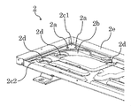
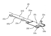
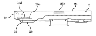
- FIG. 6 is a perspective view of the mounting plate 25 having an L shape in plan view installed on the bottom plate 2.
- FIG. 7 is an enlarged perspective view of the mounting plate 25 in the vicinity of the corner 25j.
- FIG. 8 is an enlarged perspective view of the vicinity of the longitudinal end portion 25 i of the mounting plate 25.
- the mounting plate 25 has two fitting holes 25a to be fitted into the two projections 2a (FIG. 5) of the bottom plate 2, and leg portions provided on the lower surfaces of the short side end portion 25h and the long side end portion 25i.
- a drainage invitation portion 25e having a hollow shape for facilitating drainage of water generated on the mounting surface 25d and a drainage opening portion 25f having an opening for facilitating drainage of water are provided.
- the heat exchanger mounting surface 25d has an L shape in plan view that is similar to the L shape of the heat exchanger 16.
- the heat exchanger 16 is placed on a planar heat exchanger placement surface 25d.
- the heat exchanger placement surface 25d is not provided with a holding part and a groove part for fixing the heat exchanger 16 from both sides in the thickness direction.
- the fitting hole 25a is provided in the extending portion 25g extending outward from the corner portion 25j of the heat exchange mounting surface 25d.
- a plurality of drainage invitation portions 25e are provided at intervals on the inner end portion 25k in the width direction of the heat exchanger mounting surface 25d.
- the drainage invitation portion 25e has a hollow shape inclined in the direction of the bottom plate 2.
- the drainage invitation portion 25e is not recessed until it comes into contact with the bottom plate 2, and is formed so as to drop water onto the bottom plate 2 from a height position between the placement plate 25 and the bottom plate 2. No hole is provided in the heat exchange mounting surface 25d.
- a resin or a metal that is electrically lower than the heat exchanger 16 can be used as a material of the mounting plate 25 . Further, the mounting plate 25 can be formed integrally.
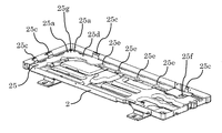
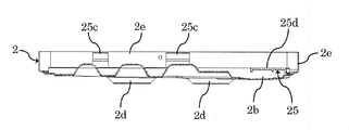
- FIG. 9 is a perspective view of the bottom plate 2 on which the mounting plate 25 is mounted.
- FIG. 10 is an enlarged perspective view of a part of the bottom plate 2 on which the mounting plate 25 is mounted.
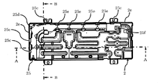
- FIG. 11 is a plan view of the bottom plate 2 on which the mounting plate 25 is installed.
- 12 is a cross-sectional view taken along the AA chain line of FIG.
- FIG. 13 is an enlarged perspective view in a broken-line frame indicated by a symbol C in FIG. 14 is a cross-sectional view taken along the line BB in FIG.
- the heat exchanger 16 of FIG. 3 is placed on the mounting plate 25 (see FIG. 2). Part of the flat tube 20 and the fins 21 of the heat exchanger 16 are in contact with the mounting plate 25.
- Two fitting holes 25 a of the mounting plate 25 are fitted into two protrusions 2 a provided in the first support portion 2 c 1 of the bottom plate 2.
- the mounting plate 25 is installed above the discharge path 2 b of the bottom plate 2.
- Leg portions 25b are provided on the lower surface of the short side end portion 25h and the lower surface of the long side end portion 25i of the mounting plate 25, respectively.
- the leg portion 25b of the short side end portion 25h is placed on the third support portion 2c3 of the bottom plate 2, and the leg portion 25b of the long side end portion 25i is placed on the second support portion 2c2 of the bottom plate 2.
- the place where the mounting plate 25 contacts the bottom plate 2 is only the first support portion 2c1, the second support portion 2c2, and the third support portion 2c3.
- the 2nd support part 2c2 and the 3rd support part 2c2 are provided in the position higher than the drainage channel 2b.
- the drainage invitation portion 25e is provided at a position corresponding to the discharge hole 2d of the bottom plate 2, that is, above the drainage hole 2d.
- the heat exchanger 16 is fixed on the mounting plate 25 by its own weight.
- the hole 25a does not function as a discharge hole.
- the horizontal position of the mounting plate 25 is regulated by a position regulating unit 25c provided on the heat exchange mounting surface 25d.
- a plurality of position restricting portions 25c are provided at intervals on the outer end portion 25m in the width direction of the heat exchange mounting surface 25d.
- the position restricting portion 25 c is in contact with the inner surface of the flange portion 2 e of the bottom plate 2, thereby restricting the horizontal position of the mounting plate 25 on the bottom plate 2.
- the position restricting portion 25c is formed so as to be continuous with the vertical surface 25c1 and the vertical surface 25c1 formed vertically on the heat exchange placement surface 25d, and to be inclined with respect to the heat exchange placement surface 25d.
- the outdoor unit 100 has an inclined surface 25c2 and a parallel surface 25c3 that is formed continuously with the inclined surface 25c2 and is formed in parallel to the heat exchange mounting surface 25d.
- the lower surface of the heat exchanger 16 is slid along the inclined surface 25c2, and the heat exchanger 16 is moved onto the mounting plate 25.
- the position of the heat exchanger 25 in the horizontal direction can be regulated by arranging the back surface and the left side surface of the heat exchanger 16 in contact with the vertical surface 25c1 of the position regulating unit 25c.
- the side plates 23 and 24 of the heat exchanger 16 are fixed to the casing 1 (FIG. 1) of the outdoor unit 100 with screws.
- the heat exchanger 16 is mounted on a planar heat exchange mounting surface 25 d of a mounting plate 25 installed on the bottom plate 2. According to such a structure, the heat exchanger 16 and the bottom plate 2 can be prevented from coming into contact with each other through water and dust generated in the housing 1. In particular, since a structure such as a spacer is not provided directly under the heat exchanger 16, water and dust generated in the housing 1 adhere to the mounting plate 25 immediately below the heat exchanger 16. Even in this case, the heat exchanger 16 and the bottom plate 2 are not immediately electrically connected. Therefore, according to the outdoor unit 100 of the present embodiment, the occurrence of dissimilar metal contact corrosion can be prevented.
- the heat exchange mounting surface 25d has a planar shape, and is not provided with a sandwiching portion that sandwiches the heat exchanger 16 from both sides in the thickness direction and a groove portion into which the heat exchanger 16 is fitted. For example, once water and dust are collected in the sandwiching portion or the groove portion having a U-shaped or H-shaped cross section, it is difficult to discharge, and dissimilar metal contact corrosion is easily promoted.
- the mounting plate 25 of the present embodiment has a structure that supports the heat exchanger 16 from below with a surface, and does not include a clamping part or a groove part that makes it difficult to discharge water and dust. Therefore, even if water or deposits are generated on the mounting plate 25, they are easily discharged onto the base 2 and the effect of dissimilar metal contact corrosion hardly occurs.
- the heat exchanger is fitted on the mounting plate, a plurality of heat exchangers according to variations in dimensions in the depth direction (column direction in the case of a plurality of rows) are used.
- a mounting plate must be prepared.
- the heat exchanger 16 is mounted on the flat heat exchange mounting surface 25d, it is possible to easily cope with a change in the depth direction of the heat exchanger 16.
- the width of the heat exchange mounting surface 25d can be dealt with only by increasing or decreasing the width in correspondence with the dimension of the heat exchanger 16 in the depth direction.
- a single mounting plate 25 can be used for both a heat exchanger having a large dimension in the depth direction and a small heat exchanger.
- the mounting plate 25 is fixed on the bottom plate 2 by the weight of the heat exchanger 16, and does not require other fixing means such as screw fixing. Therefore, there is an advantage that it is easy to disassemble, easy to separate garbage at the time of disposal, and friendly to the environment. The number of parts can be reduced by not using screws for fixing.
- the heat exchanger 16 is fixed by its own weight only by being placed on the heat exchange mounting surface 25d. Therefore, unlike the present embodiment, the assembling work is easier as compared with the prior art in which the heat exchanger is fitted to the mounting plate. In addition, since it is technically easy to provide the heat exchanger placement surface 25d horizontally with respect to the bottom surface of the bottom plate 2, the heat exchanger 16 is not mounted with an inclination.
- the mounting plate 25 is provided above the discharge path 2 b of the bottom plate 2. With this configuration, it is possible to easily discharge the water and dust dropped from the mounting plate 25 to the outside of the housing 1 while isolating the heat exchanger 16 from the discharge path 2b so as not to come into contact with water and dust.
- the mounting plate 25 has a heat exchange mounting surface 25d having a L-shaped shape in plan view that is similar to the shape of the L-shaped heat exchanger 16 in plan view.
- the heat exchanger placement surface 25d is provided in a range from the short-side end 25h to the long-side end 25i of the heat exchanger 16. According to such a configuration, the heat exchanger 16 fixed to the mounting plate 25 by its own weight can be stably supported.
- the heat exchanger 16 is the second most expensive item after the compressor 14, so that it can be stably supported by supporting not the part of the heat exchanger 16 but the whole.
- the heat exchange mounting surface 25 d is provided over the entire lower surface of the heat exchanger 16, water and dust accumulate on the bottom plate 2 immediately below the heat exchanger 16, and the deposit is deposited on the mounting plate 25. Even when the height position is reached, it is possible to prevent the deposit from contacting the heat exchanger mounting surface 25d. Therefore, the effect of preventing different metal contact corrosion can be enhanced.
- the fitting hole 25 a of the mounting plate 25 is fitted into the protruding portion 2 a of the first support portion 2 c 1 located at a position higher than the discharge path 2 b of the bottom plate 2.
- the heat exchanger 16 is installed at a position higher than the discharge path 2b. Therefore, water and dust generated in the housing 1 can be drained outside the housing 1 without contacting the heat exchanger 16.
- the bottom plate is interposed therebetween. 2 and the heat exchanger 16 can be prevented from coming into immediate contact with each other, and the occurrence of dissimilar metal contact corrosion can be prevented.
- the fitting hole 25a of the mounting plate 25 is provided in the extending portion 25g extending outward from the corner portion 25j of the L-shaped heat exchange mounting surface 25d in plan view. According to such a configuration, even when water and dust accumulate in the fitting hole 25a where water and dust easily accumulate compared to the planar heat exchange mounting surface 25d, heat exchange is performed via the deposit. The container 16 and the bottom plate 2 can be prevented from contacting each other.
- the mounting plate 25 is in contact with the bottom plate 2 only below the short side end portion 25h, the long side end portion 25i, and the corner portion 25j of the L-shaped heat exchange mounting surface 25d in plan view. According to this structure, there are few contact locations of the mounting board 25 and the bottom plate 2, and the mounting board 25 does not obstruct the flow of water and dust on the discharge path 2b. Therefore, water and dust can be smoothly discharged out of the housing 1, and the effect of preventing the contact corrosion of dissimilar metals can be enhanced.
- Leg portions 25b are provided on the lower surfaces of the short-side end portion 25h and the long-side end portion 25i of the heat exchanger placement surface 25d.
- the leg portion 25b is placed on the second support portion 2c2 and the third support portion 2c3 of the bottom plate 2.
- a plurality of drainage invitation portions 25e each having a hollow shape for dropping water generated on the placement plate 25 to the bottom plate 2 are provided at intervals on the inner end portion 25k in the width direction of the heat exchange placement surface 25d. It has been.
- the drainage invitation portion 25e is not recessed until it comes into contact with the bottom plate 2, and is formed so as to drop water from a height position between the placement plate 25 and the bottom plate 2. According to such a configuration, it is easy to drop the water generated on the mounting plate 25 to the bottom plate 2 and does not keep in contact with the water dropped on the bottom plate 2, thereby enhancing the effect of preventing the contact corrosion of different metals. Can do.
- the drain opening 25f also has an effect of facilitating dropping of water on the mounting plate 25 to the bottom plate 2.
- the drainage invitation portion 25e is provided at a position corresponding to the discharge hole 2d provided on the discharge path 2b of the bottom plate 2, that is, directly above the discharge hole 2d. According to this configuration, the water dropped on the bottom plate 2 from the drain invitation part 25e can be drained directly from the discharge hole 2d. Therefore, the retention of water in the housing 1 can be eliminated and the effect of preventing the contact corrosion of different metals can be enhanced.
- the position restriction of the mounting plate 25 in the horizontal direction is performed by a position restriction portion 25 c having a projection shape provided on the mounting board 25.
- the position restricting portion 25 c is applied to the inner surface of the flange portion 2 e of the bottom plate 2.
- the position restricting portion 25c includes an inclined surface 25c2. According to this configuration, when the outdoor unit 100 is manufactured, when the heat exchanger 16 is mounted on the mounting plate 25, the lower surface of the heat exchanger 16 is slid along the inclined surface 25c2, and the heat exchanger 16 is moved. Can be guided onto the bottom plate 2. This facilitates the work of mounting the heat exchanger 16 on the bottom plate 2, shortening the manufacturing time and reducing the cost.
- the mounting plate 25 an integrally formed plate can be used. By adopting an integral structure, the number of parts is reduced, and the assembly time of the outdoor unit 100 can be reduced. Further, since the strength of the mounting plate 25 is increased by integral molding, the heat exchanger 16 can be more stably mounted on the mounting plate 25.
- Resin can be used for the material of the mounting plate 25. Even if a mixture of water and dust accumulates on the bottom plate 2 immediately below the heat exchanger 16 and reaches the height position of the mounting plate 25, the bottom plate 2 and the heat exchanger 16 are made of resin. Since it is electrically insulated by the mounting portion plate 25, it is possible to prevent the occurrence of dissimilar metal pipe contact corrosion.
- the configuration of the present embodiment is particularly effective when the heat exchanger 16 is a heat exchanger in which aluminum is used as the material for the flat tubes 20 and the fins 21.
- a material of the bottom plate 2 an iron plate or a galvanized steel plate can be used.
- the metal constituting the heat exchanger 16 is an electrically base metal than the metal constituting the bottom plate 2, so that the heat exchanger 16 and the bottom plate 2 are generated in the housing 1. Corrosion due to contact with dissimilar metal pipes may occur when electrically connected via deposits such as water and dust.
- the heat exchanger 16 and the bottom plate 2 can be prevented from contacting with each other through water. Therefore, even if the heat exchanger 16 is an aluminum heat exchanger, it is possible to prevent contact corrosion of dissimilar metal pipes.
- the casing 1 of the outdoor unit 100 includes the bottom plate 2 and the various panels 3 to 8.
- the casing 1 according to the present embodiment is not limited as long as it can store the blower chamber 9 and the machine chamber 10.
- the configuration is not limited to one.
- the right side panel that can cover the entire right side is provided, and the service panel 4 and the cover panel 7 are not provided.
- two protrusions 2a of the bottom plate 2 and two fitting holes 25a of the mounting plate 25 are provided, but three or more may be provided respectively.
- a plurality of drainage invitation portions 25e are provided, but only one can be provided.
- the mounting plate 25 is in contact with only the first to third support portions 2c1 to 2c3 on the bottom plate 2, but the mounting plate 25 is attached to the bottom plate 2 as necessary for reinforcement or the like. These portions other than the support portions 2c1 to 2c3 can be appropriately brought into contact with each other.
- two position restricting portions 25c are provided on each of the long side and short sides of the heat exchanger placement surface 25d.
- the present invention is not limited to this, and the long side and short sides are not limited thereto. It is sufficient that at least one is provided on each side.
- the 2nd support part 2c2 and the 3rd support part 2c3 are provided in the position higher than the drainage channel 2b, they can also be provided in the same height position as the drainage channel 2b. Even if it is provided at the same height, a space can be formed between the mounting plate 25 and the drainage channel 2b by providing the leg portion 25b, so that water and dust generated in the housing 1 can be removed. It is possible to prevent the heat exchanger 16 and the bottom plate 2 from coming into contact with each other.
Landscapes
- Engineering & Computer Science (AREA)
- Mechanical Engineering (AREA)
- General Engineering & Computer Science (AREA)
- Physics & Mathematics (AREA)
- Thermal Sciences (AREA)
- Chemical & Material Sciences (AREA)
- Combustion & Propulsion (AREA)
- Other Air-Conditioning Systems (AREA)
Abstract
冷媒配管の材料にアルミニウムを用いた、いわゆるオールアルミ熱交換器においては、室外機の鉄製底板との異種金属接触によって冷媒配管が腐食する可能性が高まる。本発明による空気調和機の室外機は、筐体の底板上に設置され、熱交換器が載せられる平面状の熱交搭載面を有する載置板を備える。かかる構成によれば、筐体内に生じた水及び埃を熱交換器搭載面から底板上に落下させて筐体外に排出させることができる。その結果、空気調和機の熱交換器としてオールアルミ熱交換器を用いた場合であっても、冷媒漏洩を防止することができる。
Description
この発明は、熱交換器が搭載される空気調和機の室外機に関する。
従来、空気調和機の室外機に搭載される熱交換器は、室外機の筐体の底板上に直に載せられていた。かかる構造において、熱交換器の材料にアルミニウムを用い、底板の材料に鉄を用いた場合には、異種金属接触腐食が生じ得る。これまで、熱交換器の冷媒配管の材料には銅が用いられていたが、近年、冷媒配管の材料にもアルミニウムを用いた、いわゆるオールアルミ熱交換器が空気調和機の室外機に搭載されるようになってきている。オールアルミ熱交換器の場合、銅の冷媒配管を用いた熱交換器に比較して、異種金属接触腐食による冷媒漏洩が生じやすくなる。異種金属接触腐食を抑制する手段として、例えば、特許文献1には、底板と熱交換器との間にアルミニウムよりも電気的に卑な金属で構成したスペーサを配置した構成が開示されている。
特許文献1の構成においては、底板と熱交換器の底面とが直方体形状の2つのスペーサを介して繋がっている。かかる構成の場合、室外機の筐体内に生じた水及び埃がスペーサに付着すると、熱交換器と底板とが水及び埃を介して電気的に接続され、異種金属接触腐食が生じてしまうという問題があった。また、スペーサに水及び埃が一旦付着すると、これらの付着物がその場にとどまり続け、異種金属接触腐食を促進してしまうという問題もあった。また、2つのスペーサの間の底板上に水と埃の混合物が堆積して熱交換器の底面にまで至った場合には、底板と熱交換器底面とがその堆積物を介して電気的に接続されてしまうという問題もあった。
この発明は、上記した課題を解決するためになされたものであり、熱交換器の異種金属接触腐食の発生を防止することができる空気調和機の室外機を提案することを目的とする。
この発明に係る空気調和機の室外機は、金属製の底板と、前記底板の金属とは異なる金属を材料に用いた熱交換器と、前記底板上に設置され、前記熱交換器が載せられる熱交搭載面を有する載置板と、を備えることを特徴とする。
この発明の空気調和機の室外機によれば、熱交換器の異種金属接触腐食の発生を防止することができる。
実施の形態1.
以下、本発明の実施の形態1による空気調和機の室外機100について、図面を参照しつつ説明する。
以下、本発明の実施の形態1による空気調和機の室外機100について、図面を参照しつつ説明する。
図1は、空気調和機の室外機100の外観の斜視図である。室外機100の筺体1は、筐体1の底部をなすベースパンである底板2と、正面側に設けられた正面パネル3と、正面側及び右側面の一部を覆うサービスパネル4と、右側面に設けられた右側面パネル5と、左側面に設けられた左側面パネル6と、右側面下部を覆うカバーパネル7と、上側に設けられた天面パネル8と、からなる。
図2は、室外機100の内部の斜視図である。室外機100の内部は、セパレータ11によって送風機室9と機械室10とに分けられている。
送風機室9には、平面視L字形状の熱交換器16と、熱交換器16に向けて送風するファン17と、ファン17を駆動するファンモーター18と、ファンモーター18を固定するモーターサポート19と、底板2上に設置され、熱交換器16が載せられる載置板25と、が備えられている。
機械室10には、各部品への電力供給などを行う電気品12と、電気品12が収められている電気品箱13と、冷媒を圧縮して冷媒配管(図示せず)に送り出す圧縮機14と、圧力容器15と、が備えられている。室内熱交換器などを備える室内機(図示せず)から流入した冷媒は、圧縮機14により圧縮され、冷媒配管を通り、送風機室9に配置された熱交換器16へ送られる。室外機100と室内機の冷媒循環によって冷房、暖房機能が実現される。
図3は、熱交換器16の斜視図である。熱交換器16は、冷媒配管である扁平管20と、ファン17からの風を受けるフィン21と、冷媒流路であるヘッダーパイプ22と、フィン21の両端部に取り付けられているサイドプレート23及び24と、を備える。熱交換器16は、底板2上に設置された載置板25(図6~図11参照)の上に載せられる。サイドプレート23及び24が室外機100の筐体1にネジ固定される。扁平管20及びフィン21の各々の材料にはアルミニウムを用いることができる。
図4は、底板2の斜視図である。図5は、底板2の一部の拡大斜視図である。底板2は、底板2上に設置される載置板25(図6~図11参照)の位置決めをするための突起部2aと、筐体1内に進入した雨水、埃、及び熱交換によって生じたドレン水など(以下、筐体1内に生じた水及び埃、と称する)を排出するための排出路2bと、平面視L字形状の載置板25の角部25jを下方から支持する第1支持部2c1と、載置板25の短手側端部25hが載置される第2支持部2c2と、載置板25の長手側端部25iが載置される第3支持部2c3と、筐体1内に生じた水及び埃を筐体1外に排水する排出穴2dと、筐体1の前後左右のパネルの下部を固定するためのフランジ部2eと、を有する。
第1支持部2c1は、平面視長方形状の底板2の4つの角のうちの1つに設けられている。2つの突起部2aが第1支持部2c1上に形成されている。第1~第3支持部2c1~2c3は、排出路2b及び排出穴2dよりも高い位置に設けられている。排出路2bは平面視L字形状であり、その角部が第1支持部2c1の下方に位置する。排出路2bの長手側が筐体1(図1)内の背面側に形成されており、短手側が筐体1内の左側に形成されている。排出路2bは、底板2に絞り加工を施すことによって形成することができる。複数個の排出穴2dが排出路2b上に間隔をおいて形成されている。排出穴2dは、第2支持部2c2などの、排出路2b以外の箇所に設けることもできる。排出穴2dは、平面視円形状の開口である。フランジ部2eは、底板2の周縁に沿って設けられ、底板2の底面に対して垂直な内側面を有する。底板2の材料には、アルミニウムよりも電気的に貴な材料、すなわちイオン化傾向の小さい材料を用いることができる。例えば、鉄板、亜鉛めっき鋼板を用いることができる。
図6は、底板2に設置される平面視L字形状の載置板25の斜視図である。図7は、載置板25の角部25j付近の拡大斜視図である。図8は、載置板25の長手側端部25i付近の拡大斜視図である。載置板25は、底板2の2つの突起部2a(図5)に嵌め込む2つの嵌め込み穴25aと、短手側端部25h及び長手側端部25iの各々の下面に設けられた脚部25bと、底板2のフランジ部2eの内側面に接触させて載置板25の水平方向の位置を規制する位置規制部25cと、熱交換器16が載せられる熱交載置面25dと、熱交載置面25dに生じた水を排水し易くするための窪み形状からなる排水誘い部25eと、水を排水し易くするための開口からなる排水開口部25fと、を有する。
熱交載置面25dは、熱交換器16のL字形状と相似形をなす平面視L字形状である。熱交換器16は平面状の熱交載置面25dに載置される。熱交載置面25dには、熱交換器16を厚み方向両側から挟んで固定するための挟持部及び溝部は設けられていない。嵌め込み穴25aは、熱交載置面25dの角部25jから外側に伸びる延出部25gに設けられている。複数の排水誘い部25eが、熱交載置面25dの幅方向の内側の端部25kに間隔をおいて設けられている。排水誘い部25eは、底板2の方向に傾斜した窪み形状からなる。排水誘い部25eは、底板2と接触する位置までは窪んでおらず、載置板25と底板2との間の高さ位置から水を底板2上に落とすように形成されている。熱交載置面25dには穴が設けられていない。載置板25の材料としては、樹脂又は熱交換器16よりも電気的に卑な金属を用いることができる。また、載置板25は、一体形成されたものを用いることができる。
図9は、載置板25が搭載された底板2の斜視図である。図10は、載置板25が搭載された底板2の一部の拡大斜視図である。図11は、載置板25が設置された底板2の平面図である。図12は、図9のA-A鎖線における断面図である。図13は、図12の符号Cによって示される破線枠内の拡大斜視図である。図14は、図9のB-B鎖線における断面図である。図9~図14では図示を省略しているが、図3の熱交換器16が載置板25の上に載せられる(図2参照)。熱交換器16の扁平管20及びフィン21の一部は載置板25に接触する。載置板25の2つの嵌め込み穴25aが、底板2の第1支持部2c1に設けられた2つの突起部2aに嵌めこまれている。
載置板25は、底板2の排出路2bの上方に設置されている。載置板25の短手側端部25hの下面及び長手側端部25iの下面には、それぞれ脚部25bが設けられている。短手側端部25hの脚部25bは底板2の第3支持部2c3上に載せられ、長手側端部25iの脚部25bは底板2の第2支持部2c2上に載せられている。載置板25の底板2への接触箇所は、第1支持部2c1、第2支持部2c2、及び第3支持部2c3のみである。第2支持部2c2及び第3支持部2c2は、排水路2bよりも高い位置に設けられている。排水誘い部25eは、底板2の排出穴2dに対応する位置すなわち排水穴2dの上方に設けられている。熱交換器16は、自重によって載置板25上に固定されている。なお、載置板25の穴部25aには底板2の突起部2aが嵌め込まれるので、穴部25aは排出穴としては機能していない。
載置板25の水平方向の位置は、熱交載置面25d上に設けられた位置規制部25cによって規制される。複数の位置規制部25cが、熱交載置面25dの幅方向の外側の端部25mに間隔をおいて設けられている。位置規制部25cは底板2のフランジ部2eの内側面に接触しており、これによって、底板2上における載置板25の水平位置が規制されている。位置規制部25cは、熱交載置面25d上に垂直に形成された垂直面25c1と、垂直面25c1と連続して形成され、熱交載置面25dに対して傾斜するように形成された傾斜面25c2と、傾斜面25c2に連続して形成され、熱交載置面25dに対して平行に形成された平行面25c3と、を有する。室外機100の製造時、熱交換器16を載置板25上に載せる際に、熱交換器16の下面を傾斜面25c2に沿って滑らせて、熱交換器16を載置板25上へ導くことができる。また、熱交換器16の背面及び左側面を位置規制部25cの垂直面25c1に接触させて配置することで、熱交換器25の水平方向の位置を規制することができる。熱交換器16のサイドプレート23及び24が室外機100の筐体1(図1)にネジ固定されている。
熱交換器16は、底板2の上に設置された載置板25の平面状の熱交載置面25dに載せられている。かかる構造によれば、熱交換機16と底板2とが、筐体1内に生じた水及び埃を介して接触することを防止できる。特に、熱交換器16の直下にスペーサのような部材を設けない構造とすることができるので、たとえ筐体1内に生じた水及び埃が熱交換器16の直下の載置板25に付着した場合であっても、熱交換機16と底板2とが直ちに電気的に接続されることはない。それゆえ、本実施形態の室外機100によれば、異種金属接触腐食の発生を防止することができる。
熱交載置面25dは、平面状であり、熱交換器16をその厚み方向の両側から挟み込む挟持部、及び熱交換器16を嵌め込む溝部は設けられていない。例えば断面がU字型又はH字型の構造からなる挟持部又は溝部に水及び埃が一旦溜まると排出されにくく、異種金属接触腐食が促進され易い。これに対して、本実施形態の載置板25は、熱交換器16を下方から面によって支持する構造であり、水及び埃の排出を困難にする挟持部や溝部を備えていない。それゆえ、仮に載置板25上に水や堆積物が生じたとしても、これらがベース2上に排出され易く、異種金属接触腐食が生じ難いという効果を奏する。
本実施形態とは異なり、仮に熱交換器を載置板に嵌めこむ方式とした場合には、熱交換器の奥行き方向(複数列から成る場合の列方向)の寸法のバリエーションに合せて複数の載置板を用意しなければならない。これに対して、本実施形態の場合、平面状からなる熱交載置面25d上に熱交換器16を載せているので、熱交換器16の奥行き方向の変化にも容易に対応できる。すなわち、熱交載置面25dの幅を、熱交換器16の奥行き方向の寸法に対応させて増減させるだけ対応可能である。また、熱交載置面25dの幅を大きめに形成しておくことで、奥行き方向の寸法の大きい熱交換器も小さい熱交換器も1つの載置板25を流用することができる。
載置板25は、熱交換器16の重量によって底板2上に固定されており、ネジ固定などの他の固定手段を要しない。それゆえ、分解が容易で廃却時のゴミの分別もし易く、環境にも優しいという利点もある。固定にネジなどを使用しないことによって部品点数も削減可能である。熱交換器16は、熱交載置面25dに置くだけで自重によって固定されている。それゆえ、本実施例とは異なり、熱交換器を載置板に対して嵌めこむ従来技術に比較して組み立て作業も容易である。また、熱交載置面25dを底板2の底面に対して水平に設けることは技術的に容易であるので、熱交換器16が傾いて搭載されることも無い。
熱交載置面25cには穴は設けられていない。かかる構成によれば、仮に底板2の排出穴2dが塞がり、水又は埃が逆流して載置板25の高さ位置に達したとしても、熱交換器16と異物が触れ続けるリスクを軽減し、異種金属接触腐食を生じ難くすることができる。
載置板25は、底板2の排出路2bの上方に設けられている。かかる構成によって、熱交換器16を排出路2bから隔離して水及び埃と接触しないようにしつつ、載置板25から落下した水及び埃を筐体1外に排出し易くすることができる。
載置板25は、平面視L字型の熱交換器16の形状と相似形をなす平面視L字型の形状からなる熱交載置面25dを有する。熱交載置面25dは、熱交換器16の短手側端部25hから長手側端部25iに至る範囲に設けられている。かかる構成によれば、自重によって載置板25に固定される熱交換器16を安定的に支持することができる。一般的に、室外機100において熱交換器16は圧縮機14に次ぐ重量物であるので、熱交換器16の一部ではなく全体を支えることによって安定的に支持することができる。また、熱交載置面25dが熱交換器16の下面全体に亘って設けられているので、熱交換器16の直下の底板2に水及び埃が堆積し、その堆積物が載置板25の高さ位置まで達したとしても、熱交搭載面25dへの堆積物の接触を阻止できる。それゆえ、異種金属接触腐食を防止する効果を高めることができる。
載置板25の嵌め込み穴25aは、底板2の排出路2bよりも高い位置にある第1支持部2c1の突起部2aに嵌め込まれている。かかる構造によって、熱交換器16は、排出路2bよりも高い位置に設置される。それゆえ、筐体1内に生じた水及び埃を熱交換器16に接触させることなく、筐体1の外に排水することができる。また、熱交換器16と排水路2bとの間に空間が形成されているので、たとえ排出穴2dがつまって排出路2bに水及び埃が逆流した場合であっても、これらを介して底板2と熱交換器16とが直ちに接触してしまうことを防止でき、異種金属接触腐食の発生を防止することができる。
底板2の突起部2a及び載置板25の嵌め込み穴25aはそれぞれ2つ設けられ、突起部2aに嵌め込み穴25aが嵌め込まれている。かかる構成によれば、載置板25及び熱交換器16が底板2上で水平方向に回転せず、安定して固定される。それゆえ、回転による熱交換器16及び載置板25と底板2との不測の接触を防止できる。
載置板25の嵌め込み穴25aは、平面視L字形の熱交載置面25dの角部25jから外側に伸びる延出部25gに設けられている。かかる構成によれば、平面状の熱交載置面25dに比較して水及び埃が堆積し易い嵌め込み穴25aに水及び埃が堆積した場合であっても、その堆積物を介して熱交換器16と底板2とが接触することを防止できる。
載置板25は、平面視L字型の熱交載置面25dの短手側端部25h、長手側端部25i、及び角部25jの下方においてのみ、底板2と接触している。かかる構成によれば、載置板25と底板2との接触箇所が少なく、載置板25は排出路2b上の水及び埃の流れを妨害しない。それゆえ、水及び埃を筐体1外にスムーズに排出させることができ、異種金属接触腐食の防止効果を高めることができる。
熱交載置面25dの短手側端部25h及び長手側端部25i各々の下面には脚部25bが設けられている。脚部25bは、底板2の第2支持部2c2及び第3支持部2c3上に載せられる。かかる構成によって、載置板25と底板2との接触面積を小さくでき、且つ、載置板25と排出路2bとの間の距離を大きくすることができる。それ故、載置板25に底板2上の水及び埃を接触させ難くする効果を高めることができる。
熱交載置面25dの幅方向の内側の端部25kには、載置板25上に生じた水を底板2へ落とすための窪み形状から成る複数の排水誘い部25eが間隔をおいて設けられている。排水誘い部25eは、底板2と接触する位置までは窪んでおらず、載置板25と底板2との間の高さ位置から水を落とすように形成されている。かかる構成によれば、載置板25上に生じた水を底板2へ落としやすくなり、且つ底板2上に落とした水に接触し続けることも無いので、異種金属接触腐食の防止効果を高めることができる。排水開口部25fも、載置板25上の水を底板2へ落とし易くする効果を奏する。
排水誘い部25eは、底板2の排出路2b上に設けられた排出穴2dに対応する位置、すなわち排出穴2dの真上に設けられている。かかる構成によれば、排水誘い部25eから底板2に落とした水を排出穴2dから直接排水することができる。それゆえ、筐体1内への水の滞留を無くし、異種金属接触腐食の防止効果を高めることができる。
載置板25の水平方向の位置規制は、載置板25に設けられた突起形状からなる位置規制部25cによってなされる。位置規制部25cは、底板2のフランジ部2eの内側面にあてがわれている。これらによって、底板2上における載置板25の水平方向の位置が定まり、載置板25及び熱交換器16を安定的に固定することができる。
位置規制部25cは、傾斜面25c2を備えている。かかる構成によれば、室外機100の製造時、載置板25上に熱交換器16を搭載する際に、熱交換器16の下面を傾斜面25c2に沿って滑らせて、熱交換器16を底板2上へ導くことができる。これによって、熱交換器16を底板2上に搭載する作業が容易になり、製造時間を短縮し、コストを低減できる。
載置板25は、一体形成されたものを用いることができる。一体構造とすることによって、部品点数が少なくなり、室外機100の組立て時間を低減できる。また、一体成形によって載置板25の強度が増すので、熱交換器16を載置板25上により安定的に搭載することができる。
載置板25の材料には樹脂を用いることができる。たとえ熱交換器16の直下の底板2上に水及び埃の混合物が堆積して載置板25の高さ位置まで達した場合であっても、底板2と熱交換器16とが樹脂製の載置部板25によって電気的に絶縁されるので、異種金属管接触腐食の発生を防止できる。
本実施形態の構成は、熱交換器16が、扁平管20及びフィン21各々の材料にアルミニウムが用いられた熱交換器である場合に、特に効果が大きい。底板2の材料としては、鉄板、亜鉛めっき鋼板を用いることができる。この材料の組み合わせの場合、熱交換器16を構成する金属は、底板2を構成する金属よりも電気的に卑な金属であるので、熱交換器16と底板2とが筐体1内に生じた水及び埃などの堆積物を介して電気的に接続された場合には、異種金属管接触による腐食が生じ得る。しかしながら、本実施形態の室外機100の構成によれば、上記したように、熱交換器16と底板2とが水及びを介して接触することを防止できる。それゆえ、熱交換器16がアルミ製熱交換器であっても、異種金属管接触腐食を防止できる。
なお、本実施形態の室外機100の筐体1は、底板2と各種パネル3~8とからなるが、送風機室9及び機械室10を格納できる形態であればよく、本実施形態の筐体1の構成に限られない。例えば、右側面全体を覆うことができる右側面パネルを備え、サービスパネル4、カバーパネル7を備えない構成とすることもできる。また、本実施形態においては、底板2の突起部2a及び載置板25の嵌め込み穴25aはそれぞれ2つ設けられているが、それぞれ3つ以上とすることもできる。また、本実施形態においては、複数の排水誘い部25eが設けられているが、1つのみ設けることもできる。また、本実施形態においては、載置板25は底板2上では第1~第3支持部2c1~2c3のみに接触しているが、補強等の必要に応じて、載置板25を底板2のこれらの支持部2c1~2c3以外の箇所に適宜接触させることもできる。また、本実施形態においては、位置規制部25cは、熱交載置面25dの長手側辺、短手側辺にそれぞれ2つ設けられているが、これに限られず、長手側辺、短手側辺それぞれに少なくとも1つ設けられていればよい。また、本実施形態においては、第2支持部2c2、及び第3支持部2c3は排水路2bよりも高い位置に設けられているが、排水路2bと同じ高さ位置に設けることもできる。同じ高さ位置に設けた場合であっても、脚部25bを設けることによって、載置板25と排水路2bとの間に空間を形成できるので、筐体1内に生じた水及び埃を介して熱交換器16と底板2とが接触することを防止できる。
1 筐体、2 底板、2a 突起部、2b 排出路、2c1 第1支持部、2c2 第2支持部、2c3 第3支持部、2d 排出穴、2e フランジ部、3 正面パネル、4 サービスパネル、5 右側面パネル、6 左側面パネル、7 カバーパネル、8 天面パネル、9 送風機室、10 機械室、11 セパレータ、12 電気品、13 電気品箱、14 圧縮機、15 圧力容器、16 熱交換器、17 ファン、18 ファンモーター、19 モーターサポート、20 扁平管、21 フィン、22 ヘッダーパイプ、23 サイドプレート、24 サイドプレート、25 載置板、25a 嵌め込み穴、25b 脚部、25c 位置規制部、25c1 垂直面、25c2 傾斜面、25c3 平行面、25d 熱交載置面、25e 排水誘い部、25f 排水開口部、25g 延出部、25h 短手側端部、25i 長手側端部、25j 角部、25k 熱交載置面の幅方向の内側の端部、25m、熱交載置面の幅方向の外側の端部、100 空気調和機の室外機
Claims (18)
- 金属製の底板と、
前記底板の金属とは異なる金属を材料に用いた熱交換器と、
前記底板上に設置され、前記熱交換器が載せられる熱交搭載面を有する載置板と、を備えることを特徴とする空気調和機の室外機。 - 前記熱交載置面には、前記熱交換器が嵌め込まれる溝部が設けられていないことを特徴とする請求項1に記載の空気調和機の室外機。
- 前記熱交載置面には、穴が設けられていないことを特徴とする請求項1又は2に記載の空気調和機の室外機。
- 前記載置板は、前記底板に設けられた排出路の上方に設けられていることを特徴とする請求項1~3のいずれか1項に記載の空気調和機の室外機。
- 前記熱交換器は、平面視L字形状であり、
前記熱交載置面は、平面視L字形状であることを特徴とする請求項1~4のいずれか1項に記載の空気調和機の室外機。 - 前記底板には、前記排出路よりも高い位置に突起部が設けられており、
前記載置板には、嵌め込み穴が設けられており、前記嵌め込み穴が前記突起部に嵌め込まれていることを特徴とする請求項1~5のいずれか1項に記載の空気調和機の室外機。 - 前記突起部及び前記嵌め込み穴は2つずつ設けられていることを特徴とする請求項6に記載の空気調和機の室外機。
- 前記嵌め込み穴は、前記熱交載置面の角部から外側に伸びる延出部上に設けられていることを特徴とする請求項6又は7に記載の空気調和機の室外機。
- 前記平面視L字型の載置板の短手側端部、長手側端部、及び角部の下方においてのみ前記底板と接触していることを特徴とする請求項1~8のいずれか1項に記載の空気調和機の室外機。
- 前記熱交載置面の短手側端部及び長手側端部各々の下面には脚部が設けられており、
前記脚部の各々は、前記底板上に載せられていることを特徴とする請求項9に記載の空気調和機の室外機。 - 前記熱交載置面には、前記底板と前記載置板との間の高さ位置まで窪んだ形状から成る排水誘い部が設けられていることを特徴とする請求項1~10のいずれか1項に記載の空気調和機の室外機。
- 前記排出路には、排出穴が設けられており、
前記排水誘い部は、前記排出穴の上に設けられていることを特徴とする請求項11に記載の空気調和機の室外機。 - 前記底板には、その周縁に沿って、その底面に対して垂直な内側面を有するフランジ部が設けられており、
前記載置板には、突起形状からなる位置規制部が設けられており、
前記位置規制部は、前記フランジ部の内側面に接触していることを特徴とする請求項1~12のいずれか1項に記載の空気調和機の室外機。 - 前記位置規制部は、前記熱交載置面上に垂直に形成された垂直面と、前記垂直面と連続して形成され、前記熱交載置面に対して傾斜するように形成された傾斜面と、前記傾斜面に連続して形成され、前記熱交載置面に対して平行に形成された平行面と、を有することを特徴とする請求項13に記載の空気調和機の室外機。
- 前記載置板は、一体的に形成されたものであることを特徴とする請求項1~14のいずれか1項に記載の空気調和機の室外機。
- 前記載置板の材料は、樹脂であることを特徴とする請求項1~15のいずれか1項に記載の空気調和機の室外機。
- 前記熱交換器の金属材料は、前記底板の金属材料よりも電気的に卑な金属であることを特徴とする請求項1~16のいずれか1項に記載の空気調和機の室外機。
- 前記熱交換器の金属材料はアルミニウムであり、
前記底板の金属材料は鉄であることを特徴とする請求項17に記載の空気調和機の室外機。
Priority Applications (5)
| Application Number | Priority Date | Filing Date | Title |
|---|---|---|---|
| US16/096,087 US10816227B2 (en) | 2016-07-25 | 2016-07-25 | Outdoor unit for an air-conditioning apparatus having L-shaped heat exchanger and placement plate for same |
| EP16905689.2A EP3367008B1 (en) | 2016-07-25 | 2016-07-25 | Outdoor unit for air conditioner |
| JP2018530204A JP6618624B2 (ja) | 2016-07-25 | 2016-07-25 | 空気調和機の室外機 |
| PCT/JP2016/071681 WO2018020536A1 (ja) | 2016-07-25 | 2016-07-25 | 空気調和機の室外機 |
| CN201680087032.7A CN109564013B (zh) | 2016-07-25 | 2016-07-25 | 空调机的室外机 |
Applications Claiming Priority (1)
| Application Number | Priority Date | Filing Date | Title |
|---|---|---|---|
| PCT/JP2016/071681 WO2018020536A1 (ja) | 2016-07-25 | 2016-07-25 | 空気調和機の室外機 |
Publications (1)
| Publication Number | Publication Date |
|---|---|
| WO2018020536A1 true WO2018020536A1 (ja) | 2018-02-01 |
Family
ID=61015737
Family Applications (1)
| Application Number | Title | Priority Date | Filing Date |
|---|---|---|---|
| PCT/JP2016/071681 Ceased WO2018020536A1 (ja) | 2016-07-25 | 2016-07-25 | 空気調和機の室外機 |
Country Status (5)
| Country | Link |
|---|---|
| US (1) | US10816227B2 (ja) |
| EP (1) | EP3367008B1 (ja) |
| JP (1) | JP6618624B2 (ja) |
| CN (1) | CN109564013B (ja) |
| WO (1) | WO2018020536A1 (ja) |
Families Citing this family (3)
| Publication number | Priority date | Publication date | Assignee | Title |
|---|---|---|---|---|
| WO2021205499A1 (ja) * | 2020-04-06 | 2021-10-14 | 三菱電機株式会社 | 室外機 |
| KR102899429B1 (ko) * | 2020-04-21 | 2025-12-12 | 삼성전자주식회사 | 공기조화기의 실외기 |
| US11421898B2 (en) | 2020-06-10 | 2022-08-23 | Trane International Inc. | Coil locator for an outdoor unit of a climate control system |
Citations (4)
| Publication number | Priority date | Publication date | Assignee | Title |
|---|---|---|---|---|
| JP2005114273A (ja) | 2003-10-09 | 2005-04-28 | Matsushita Electric Ind Co Ltd | 空気調和機の室外ユニット |
| JP2010151387A (ja) * | 2008-12-25 | 2010-07-08 | Mitsubishi Electric Corp | 空気調和機の室外機 |
| JP2010164263A (ja) * | 2009-01-16 | 2010-07-29 | Mitsubishi Electric Corp | 空気調和機の室外ユニットおよび空気調和機 |
| JP2016084995A (ja) * | 2014-10-27 | 2016-05-19 | ダイキン工業株式会社 | 冷凍装置の室外ユニット |
Family Cites Families (38)
| Publication number | Priority date | Publication date | Assignee | Title |
|---|---|---|---|---|
| US4748828A (en) * | 1987-06-29 | 1988-06-07 | Carrier Corporation | Self-draining base pan for an air conditioner |
| AU2548601A (en) * | 2000-01-14 | 2001-07-24 | Toshiba Carrier Corporation | Outdoor unit of air conditioner |
| JP3523823B2 (ja) * | 2000-02-29 | 2004-04-26 | 東芝キヤリア株式会社 | 空気調和機の室外ユニット |
| US6802361B2 (en) * | 2000-06-22 | 2004-10-12 | Air Techno Company Limited | Ceiling panel structure for a ceiling-mounted air-conditioning apparatus or the like |
| JP4467742B2 (ja) * | 2000-08-30 | 2010-05-26 | パナソニック株式会社 | 家電製品及びエア・コンディショナの切断装置、及び、家電製品及びエア・コンディショナの解体方法 |
| KR100988572B1 (ko) * | 2003-08-14 | 2010-10-18 | 삼성전자주식회사 | 공기조화기의 실외기 |
| JP2006162094A (ja) * | 2004-12-02 | 2006-06-22 | Fujitsu General Ltd | 空気調和機の室外機 |
| US7708052B2 (en) * | 2006-01-20 | 2010-05-04 | Carrier Corporation | Coil support |
| JP3992065B2 (ja) * | 2006-02-01 | 2007-10-17 | ダイキン工業株式会社 | 電装品アセンブリ及びそれを備えた空気調和装置の室外ユニット |
| JP4490475B2 (ja) * | 2007-12-25 | 2010-06-23 | 三菱電機株式会社 | 空気調和機の室内ユニット |
| EP2136168B1 (en) * | 2008-06-20 | 2020-01-15 | Electrolux Home Products Corporation N.V. | A cooling apparatus condenser, and a cooling apparatus including the same |
| IT1400737B1 (it) * | 2009-05-20 | 2013-07-02 | Sanyo Electric Co | Unita' esterna per lo scambio di calore, particolarmente in scambiatori di calore e simili. |
| JP4746122B2 (ja) * | 2009-11-06 | 2011-08-10 | シャープ株式会社 | 空気調和機の室外機 |
| JP4991904B2 (ja) * | 2010-04-26 | 2012-08-08 | シャープ株式会社 | 熱交換装置 |
| US9287759B2 (en) * | 2010-12-06 | 2016-03-15 | Mitsubishi Electric Corporation | Induction motor, compressor, air blower, and air conditioner |
| JP5447580B2 (ja) * | 2012-04-27 | 2014-03-19 | ダイキン工業株式会社 | 空調機の室外機 |
| JP2014070861A (ja) * | 2012-10-01 | 2014-04-21 | Mitsubishi Electric Corp | 空気調和機の室外機 |
| JP5831431B2 (ja) * | 2012-11-15 | 2015-12-09 | 三菱電機株式会社 | 空気調和機の室外機 |
| JP5955233B2 (ja) | 2013-01-15 | 2016-07-20 | 三菱電機株式会社 | 空気調和機の室外機 |
| JP6066736B2 (ja) | 2013-01-15 | 2017-01-25 | 三菱電機株式会社 | 空気調和機の室外機 |
| US10267527B2 (en) * | 2013-06-04 | 2019-04-23 | Mitsubishi Electric Corporation | Outdoor unit for an air-conditioning device |
| JP5929850B2 (ja) * | 2013-07-24 | 2016-06-08 | 三菱電機株式会社 | 空気調和機の室外機 |
| CN203518057U (zh) * | 2013-08-28 | 2014-04-02 | 珠海格力电器股份有限公司 | 空调室外机的电机支架及具有其的空调室外机 |
| US10215507B2 (en) * | 2014-04-15 | 2019-02-26 | Trane International Inc. | Coil support pad having condensate drainage functionality |
| CN203869193U (zh) * | 2014-04-29 | 2014-10-08 | 美的集团股份有限公司 | 空调室外机 |
| JP6218684B2 (ja) | 2014-07-02 | 2017-10-25 | 三菱電機株式会社 | 空気調和機の室外機 |
| CN105423452B (zh) * | 2014-09-12 | 2019-01-22 | Lg电子株式会社 | 空气调节器的室外机 |
| CN107110542B (zh) * | 2014-11-18 | 2021-11-30 | 东芝开利株式会社 | 室外机 |
| US10208968B2 (en) * | 2014-12-26 | 2019-02-19 | Mitsubishi Electric Corporation | Outdoor unit |
| EP3260786A4 (en) * | 2015-02-16 | 2018-10-17 | Mitsubishi Electric Corporation | Outdoor unit |
| CN107250675B (zh) * | 2015-03-06 | 2019-10-11 | 三菱电机株式会社 | 空调机 |
| WO2016151641A1 (ja) * | 2015-03-26 | 2016-09-29 | 三菱電機株式会社 | 空気調和機の室内機 |
| JP6645029B2 (ja) * | 2015-05-11 | 2020-02-12 | 富士電機株式会社 | 自動販売機 |
| WO2018011939A1 (ja) * | 2016-07-14 | 2018-01-18 | 三菱電機株式会社 | 空気調和機の室外機 |
| JP6615378B2 (ja) * | 2016-10-17 | 2019-12-04 | 三菱電機株式会社 | 空気調和装置の室外機 |
| JP6575693B2 (ja) * | 2016-11-11 | 2019-09-18 | 三菱電機株式会社 | 空気調和機の室外機 |
| EP3557149B1 (en) * | 2016-12-16 | 2021-01-20 | Mitsubishi Electric Corporation | Outdoor unit for air conditioner |
| US10816225B2 (en) * | 2018-01-08 | 2020-10-27 | Lg Electronics Inc. | Movable air conditioner |
-
2016
- 2016-07-25 EP EP16905689.2A patent/EP3367008B1/en active Active
- 2016-07-25 CN CN201680087032.7A patent/CN109564013B/zh not_active Expired - Fee Related
- 2016-07-25 US US16/096,087 patent/US10816227B2/en active Active
- 2016-07-25 WO PCT/JP2016/071681 patent/WO2018020536A1/ja not_active Ceased
- 2016-07-25 JP JP2018530204A patent/JP6618624B2/ja not_active Expired - Fee Related
Patent Citations (4)
| Publication number | Priority date | Publication date | Assignee | Title |
|---|---|---|---|---|
| JP2005114273A (ja) | 2003-10-09 | 2005-04-28 | Matsushita Electric Ind Co Ltd | 空気調和機の室外ユニット |
| JP2010151387A (ja) * | 2008-12-25 | 2010-07-08 | Mitsubishi Electric Corp | 空気調和機の室外機 |
| JP2010164263A (ja) * | 2009-01-16 | 2010-07-29 | Mitsubishi Electric Corp | 空気調和機の室外ユニットおよび空気調和機 |
| JP2016084995A (ja) * | 2014-10-27 | 2016-05-19 | ダイキン工業株式会社 | 冷凍装置の室外ユニット |
Also Published As
| Publication number | Publication date |
|---|---|
| JP6618624B2 (ja) | 2019-12-11 |
| EP3367008B1 (en) | 2019-12-25 |
| JPWO2018020536A1 (ja) | 2019-02-28 |
| EP3367008A1 (en) | 2018-08-29 |
| EP3367008A4 (en) | 2019-01-02 |
| CN109564013A (zh) | 2019-04-02 |
| US10816227B2 (en) | 2020-10-27 |
| US20190137118A1 (en) | 2019-05-09 |
| CN109564013B (zh) | 2021-09-03 |
Similar Documents
| Publication | Publication Date | Title |
|---|---|---|
| CN103998869A (zh) | 制冷装置的室外单元 | |
| JP5919513B2 (ja) | 空気調和装置の室外ユニット | |
| JP6099925B2 (ja) | 空気調和機の室外ユニット | |
| CN102141272B (zh) | 空气调节装置的室外单元 | |
| JP2012242026A (ja) | 冷凍装置の室外ユニット | |
| JP2011158137A (ja) | 空気調和装置の室外ユニット | |
| JP6618624B2 (ja) | 空気調和機の室外機 | |
| CN104081129B (zh) | 制冷装置的室外单元 | |
| JP6702341B2 (ja) | 空気調和装置の室外機 | |
| JP5496697B2 (ja) | 空気調和装置の室外ユニット | |
| JP2008202889A (ja) | エンジン駆動式ヒートポンプ | |
| JP6936160B2 (ja) | 空気調和装置の室外機 | |
| WO2012160749A1 (ja) | 冷凍装置の室外ユニット | |
| JP2017141967A (ja) | 空気調和機 | |
| JP5772590B2 (ja) | 冷凍装置の室外ユニット | |
| US12117186B2 (en) | Air conditioning appliance having an internal shield | |
| JP6028462B2 (ja) | 冷凍装置の室外機 | |
| JP6486476B2 (ja) | 空気調和機の室外機 | |
| CN108592204A (zh) | 换热设备 | |
| JP7086292B2 (ja) | 空気調和機及び空気調和機の製造方法 | |
| JP6967483B2 (ja) | 空気調和機及び室内機 | |
| JP7170895B2 (ja) | 空気調和機の室外ユニット | |
| CN215295167U (zh) | 室外机 | |
| JP5232667B2 (ja) | 天井埋込型空気調和装置 | |
| JP2022156162A (ja) | 空気調和機 |
Legal Events
| Date | Code | Title | Description |
|---|---|---|---|
| 121 | Ep: the epo has been informed by wipo that ep was designated in this application |
Ref document number: 16905689 Country of ref document: EP Kind code of ref document: A1 |
|
| ENP | Entry into the national phase |
Ref document number: 2018530204 Country of ref document: JP Kind code of ref document: A |
|
| NENP | Non-entry into the national phase |
Ref country code: DE |