WO2018020545A1 - 電動機の診断装置 - Google Patents
電動機の診断装置 Download PDFInfo
- Publication number
- WO2018020545A1 WO2018020545A1 PCT/JP2016/071705 JP2016071705W WO2018020545A1 WO 2018020545 A1 WO2018020545 A1 WO 2018020545A1 JP 2016071705 W JP2016071705 W JP 2016071705W WO 2018020545 A1 WO2018020545 A1 WO 2018020545A1
- Authority
- WO
- WIPO (PCT)
- Prior art keywords
- histogram
- unit
- calculation unit
- load torque
- abnormality
- Prior art date
- Legal status (The legal status is an assumption and is not a legal conclusion. Google has not performed a legal analysis and makes no representation as to the accuracy of the status listed.)
- Ceased
Links
Images


Classifications
-
- G—PHYSICS
- G01—MEASURING; TESTING
- G01R—MEASURING ELECTRIC VARIABLES; MEASURING MAGNETIC VARIABLES
- G01R31/00—Arrangements for testing electric properties; Arrangements for locating electric faults; Arrangements for electrical testing characterised by what is being tested not provided for elsewhere
- G01R31/34—Testing dynamo-electric machines
- G01R31/343—Testing dynamo-electric machines in operation
-
- G—PHYSICS
- G01—MEASURING; TESTING
- G01R—MEASURING ELECTRIC VARIABLES; MEASURING MAGNETIC VARIABLES
- G01R31/00—Arrangements for testing electric properties; Arrangements for locating electric faults; Arrangements for electrical testing characterised by what is being tested not provided for elsewhere
- G01R31/34—Testing dynamo-electric machines
-
- H—ELECTRICITY
- H02—GENERATION; CONVERSION OR DISTRIBUTION OF ELECTRIC POWER
- H02P—CONTROL OR REGULATION OF ELECTRIC MOTORS, ELECTRIC GENERATORS OR DYNAMO-ELECTRIC CONVERTERS; CONTROLLING TRANSFORMERS, REACTORS OR CHOKE COILS
- H02P29/00—Arrangements for regulating or controlling electric motors, appropriate for both AC and DC motors
- H02P29/02—Providing protection against overload without automatic interruption of supply
- H02P29/024—Detecting a fault condition, e.g. short circuit, locked rotor, open circuit or loss of load
- H02P29/0241—Detecting a fault condition, e.g. short circuit, locked rotor, open circuit or loss of load the fault being an overvoltage
Definitions
- the present invention relates to a motor diagnosis apparatus that is used in, for example, a control center that is a closed switchboard and diagnoses whether there is an abnormality in the motor.
- Patent Document 1 Traditionally, it measures real-time information on the motor input voltage and current and motor speed, compares the modeled results with the measured results, and evaluates the comparison results for the errors generated by subtracting the respective signals.
- a model-based failure detection system has been proposed in which an error is analyzed by a diagnostic observer to determine the presence or absence of a motor failure.
- the present invention has been made to solve the above-described problems. Even in an electric motor in which the load fluctuates, the load torque calculated from the sampled voltage and current information is statistically processed to determine whether there is an abnormality in the electric motor.
- An object of the present invention is to provide an electric motor diagnosis apparatus capable of diagnosing the motor.
- An electric motor diagnosis apparatus includes: a load torque calculation unit that calculates a load torque of the electric motor using a voltage and current sampled and input from a main circuit to which the electric motor is connected; and a calculation performed by the load torque calculation unit A histogram calculation unit that calculates an average value and a standard deviation of a probability density function of the load torque of the sampled number of samples and forms a histogram, a normal curve storage unit that preliminarily obtains and stores a histogram of the load torque at normal time, and the normal A normality stored in a curve storage unit and an abnormality determination unit that compares the histogram obtained by the histogram calculation unit to determine the presence or absence of an abnormality in the electric motor. is there.
- the load torque calculation unit that calculates the load torque of the motor using the voltage and current sampled and input from the main circuit to which the motor is connected, and the number of samples calculated by the load torque calculation unit
- a histogram calculation unit that calculates an average value and standard deviation of the probability density function of the load torque and forms a histogram
- a normal curve storage unit that preliminarily obtains and stores a histogram of normal load torque
- the normal curve storage unit Comparing the stored normal histogram and the histogram obtained by the histogram calculation unit to determine whether there is an abnormality in the motor or not, the calculation is based on the voltage and current information input by sampling. Diagnose the presence or absence of motor abnormality by statistically processing the load torque of the number of samples There is an effect that it is possible to obtain the bets diagnostic unit for an electric motor that can.
- FIG. 1 is a schematic configuration diagram showing an installation state of a motor diagnostic device according to Embodiment 1 of the present invention
- FIG. 2 is a block diagram showing a configuration of a logical operation unit of the motor diagnostic device according to Embodiment 1 of the present invention
- FIG. 3 is a block diagram showing the configuration of the storage unit of the motor diagnostic apparatus according to Embodiment 1 of the present invention
- FIG. 4 shows the sampling rate, forgetting factor, and scale factor of the motor diagnostic apparatus according to Embodiment 1 of the present invention.
- FIG. 1 is a schematic configuration diagram showing an installation state of a motor diagnostic device according to Embodiment 1 of the present invention
- FIG. 2 is a block diagram showing a configuration of a logical operation unit of the motor diagnostic device according to Embodiment 1 of the present invention
- FIG. 3 is a block diagram showing the configuration of the storage unit of the motor diagnostic apparatus according to Embodiment 1 of the present invention
- FIG. 4 shows the sampling rate, forgetting factor, and scale factor of
- FIG. 5 is a flowchart for explaining the operation of the motor diagnostic apparatus according to Embodiment 1 of the present invention
- FIG. 6 is a load torque histogram of the motor diagnostic apparatus according to Embodiment 1 of the present invention.
- FIG. 7 is an explanatory diagram for explaining the peak portion of the histogram at the time of abnormality rather than the histogram at the time of normal of the diagnosis device for electric motor according to Embodiment 1 of the present invention.
- FIG. 8 is an explanatory diagram for explaining the Mahalanobis distance in the histogram of the motor diagnosis apparatus according to the first embodiment of the present invention.
- FIG. 9 is a motor diagnosis according to the first embodiment of the present invention.
- FIG. 10 is an explanatory diagram for explaining threshold determination based on the Mahalanobis distance of the apparatus
- FIG. 11 is an explanatory diagram for explaining the peak ratios of two peak locations in the histogram at the time of abnormality of the motor diagnostic apparatus according to Embodiment 1 of the present invention
- FIG. 12 is an embodiment of the present invention. 2 is an explanatory diagram for explaining threshold determination based on a peak ratio of a motor diagnostic apparatus in FIG.
- the main circuit 2 drawn from the power system 1 includes a circuit breaker 3 for wiring, an electromagnetic contactor 4, an instrument transformer for detecting the interphase voltage of the three-phase main circuit 2 between two phases, and the like.
- a voltage detector 5 and a current detector 6 such as an instrument transformer for detecting a load current for two phases of the main circuit 2 are provided.
- a motor 7 such as a three-phase induction motor as a load is connected to the main circuit 2, and the mechanical equipment 8 is driven to operate by the motor 7.
- the motor diagnosis device 9 is mainly used in a control center which is a closed switchboard.
- the motor diagnosis device 9 includes an input unit 10, a logic operation unit 20, a storage unit 30, and an output unit 40.
- the input unit 10 inputs the voltage detected by the voltage detector 5 at a preset sampling rate (hereinafter referred to as sampling input), and samples the current detected by the current detector 6.
- sampling input a preset sampling rate
- a current input unit 12 for input, a sampling rate setting unit 13 for setting a sampling rate, and a rating information input unit 14 for inputting rating information and the like of the motor 7 are provided.
- the sampling rate setting unit 13 sets, for example, sampling for 10 seconds at 100 sampling rates per second. As a result, 1000 sampled data are obtained.
- the set sampling rate and the like are stored in the sampling rate storage unit 31 shown in FIG.
- the rating information input unit 14 inputs in advance the power supply frequency, the rated output of the motor 7, the rated voltage, the rated current, the rated rotational speed, etc., the number of magnetic poles used for the calculation of the load torque, the winding resistance value, etc.
- the rating information is information that can be easily obtained by looking at the catalog of the manufacturer of the motor 7 or the nameplate attached to the motor 7.
- the configuration of the logical operation unit 20 includes a voltage input from the voltage input unit 11 and a current input from the current input unit 12 in a d-axis direction and a q-axis direction (hereinafter referred to as a dq-axis direction) suitable for load torque calculation.
- the dq conversion calculation unit 21 that converts voltage and current
- the load torque calculation unit 22 that calculates the load torque using the voltage and current converted by the dq conversion calculation unit 21, and the load torque calculation unit 22
- the histogram calculation unit 23 that obtains a histogram using the load torque of the number of samplings, the histogram obtained by the histogram calculation unit 23, and the normal time stored in advance in the normal curve storage unit 33 shown in FIG.
- An abnormality determination unit 24 that determines whether or not the electric motor 7 and the machine facility 8 are abnormal by comparing the histograms is provided.
- the winding resistance value calculation unit 22a for obtaining the winding resistance value Rs of the stator winding of the electric motor 7, and the forgetting factor from the sampling speed.
- a forgetting factor calculation unit 22b for calculating kf and a scale factor calculation unit 22c for calculating scale factor ⁇ are provided.
- the winding resistance value Rs increases.
- Set in the information storage unit 32 detect and input the temperature of the stator winding when sampling voltage and current, and determine the winding resistance value from the correlation set by the winding resistance value calculation unit 22a. Rs can be obtained with high accuracy.
- the winding resistance value Rs may be calculated from the detected voltage and current, and the calculation of the winding resistance value calculation unit 22a is not limited to the method described above.
- the sampling rate, the forgetting factor kf, and the scale factor ⁇ have the correlation shown in FIG. 4, for example, the correlation shown in FIG. 4 obtained as a result of actual measurement by the manufacturer of the diagnostic apparatus is set in the storage unit 30 as a data table.
- the forgetting factor calculating unit 22b calculates the forgetting factor kf using the stored data table and the scale factor calculating unit 22c.
- the scale factor ⁇ is obtained and set and stored in the sampling rate storage unit 31 shown in FIG. Once the sampling rate is initially set, the sampling rate under the same conditions is applied to the motor for all subsequent diagnosis.
- the histogram calculation unit 23 is provided with an average value calculation unit 23a that calculates an average value of the load torque of the number of samplings obtained by the load torque calculation unit 22, and a standard deviation calculation unit 23b that calculates a standard deviation.
- the abnormality determination unit 24 is provided with a Mahalanobis distance determination unit 24a and a peak number determination unit 24b that determine the presence / absence of an abnormality according to an abnormality state, which will be described in detail later.
- the configuration of the storage unit 30 includes a sampling rate storage unit 31 that stores the sampling rate set by the sampling rate setting unit 13, and a rating information storage unit that stores the rating information of the motor 7 input from the rating information input unit 14.
- a normal curve storage unit 33 for storing a normal histogram serving as a criterion for abnormality determination
- a histogram storage unit 34 for storing the histogram obtained by the histogram calculation unit 23 in time series.
- the normal curve storage unit 33 is provided with an average value storage unit 33a and a standard deviation storage unit 33b for storing an average value and a standard deviation, which are original data of the histogram at the normal time, respectively.
- an average value storage unit 34a and a standard deviation storage unit 34b for storing the average value and standard deviation, which are the original data of the histogram, respectively.
- the output unit 40 includes a comparison result of normal and abnormal histograms compared by the abnormality determination unit 24, a result of trend analysis of the Mahalanobis distance by the Mahalanobis distance determination unit 24a, and a trend analysis of the peak ratio by the peak number determination unit 24b.
- a statistical result output unit 41 that displays and outputs the result and the like, and an alarm output unit 42 that outputs an alarm such as sounding an alarm sound or lighting an abnormal lamp when the abnormality determination unit 24 determines that an abnormality has occurred are provided. .
- the motor diagnosis device 9 is activated at a predetermined time interval such as an interval of 10 minutes, and performs an abnormality diagnosis of the motor 7 and the like.
- voltages vuv and vvw for two phases are input from the voltage input unit 11 at the sampling rate set by the sampling rate setting unit 13 and stored in the sampling rate storage unit 31, and two from the current input unit 12.
- the phase currents iu and iv are sampled and input.
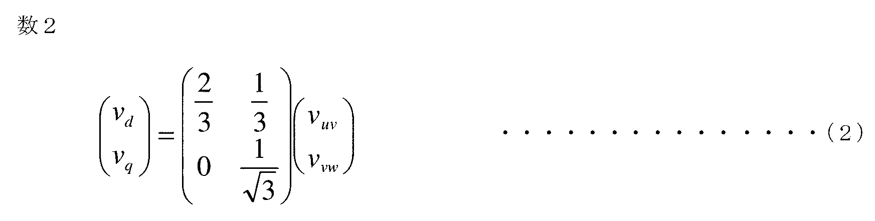
- step 102 the dq conversion calculation unit 21 converts the input voltage and current into a voltage and current in the dq axis direction.
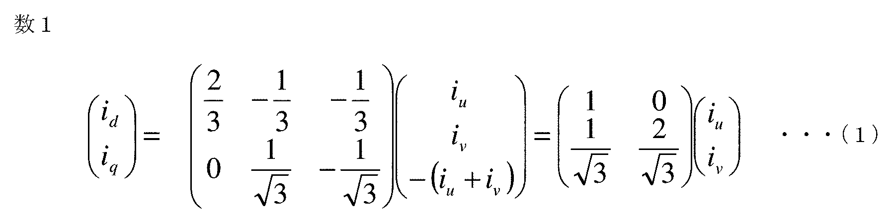
- the calculation in the dq conversion calculation unit 21 will be described. First, in the case of dq conversion of a three-phase current, only current information for two phases is sufficient when the three-phase uvw is balanced. Using iv, the current id in the d-axis direction and the current iq in the q-axis direction are calculated according to a conversion formula shown in Formula (1).
- the load torque calculation unit 22 calculates the load torque using the voltage and current in the dq axis direction converted by the dq conversion calculation unit 21.
- the calculation in the load torque calculation part 22 is demonstrated.
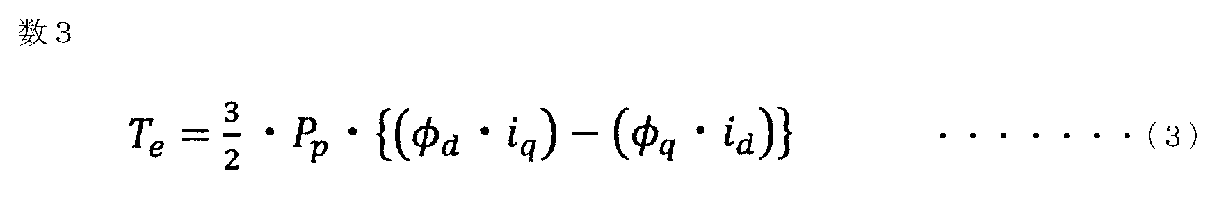
- the load torque Te is calculated by equation (3) using the number of magnetic poles Pp and the interlinkage magnetic fluxes ⁇ d and ⁇ q in the dq axis direction of the stator winding of the electric motor 7.
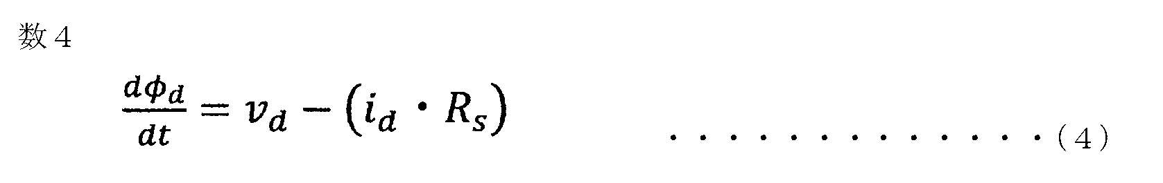
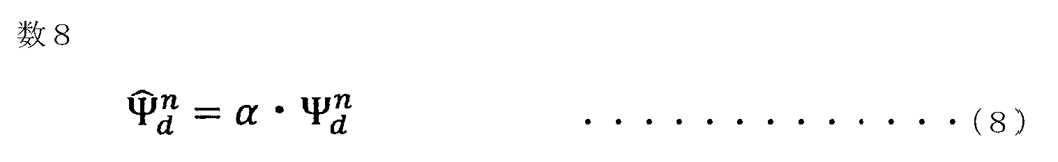
- the interlinkage magnetic fluxes ⁇ d and ⁇ q in the dq axis direction can be obtained by calculation according to equations (4) to (9). Since Expressions (4) and (5) are differentially displayed, Expressions (6) and (7) are obtained by numerical analysis, and the results of calculating Expressions (6) and (7) The scale factor ⁇ is integrated and the values calculated by the equations (8) and (9) are the identification values obtained as the final result of the flux linkage.
- the calculation result of Expression (8) corresponds to the linkage flux ⁇ d, and the calculation result of Expression (9) corresponds to the linkage flux ⁇ q.
- each symbol used in the equations (4) to (9) represents the following data.
- vd and vq are voltages in the dq axis direction calculated by the dq conversion calculation unit 21, id and iq are currents in the dq axis direction calculated by the dq conversion calculation unit 21, and Rs is calculated by the winding resistance value calculation unit 22a.
- Winding resistance value kf is a forgetting factor calculated by the forgetting factor calculating unit 22b
- ⁇ is a scale factor calculated by the scale factor calculating unit 22c
- ⁇ is a symbol for numerical analysis of the flux linkage
- a subscript n is sampling
- the subscript n ⁇ 1 is a variable indicating that the n ⁇ 1th value of sampling is used. Therefore, n is a value of 1, 2, 3,.
- ⁇ t indicates the sampling time width and is a value determined by the sampling speed. For example, if the sampling speed is 100 per second, the sampling time width ⁇ t is 0.01.
- step 104 the operation from step 101 to step 103 is repeated until sampling is completed, so that the load torque value calculated by the load torque calculation unit 22 (hereinafter referred to as load torque value) is the number of samplings, for example. 1000 will be obtained.
- load torque value the load torque value calculated by the load torque calculation unit 22
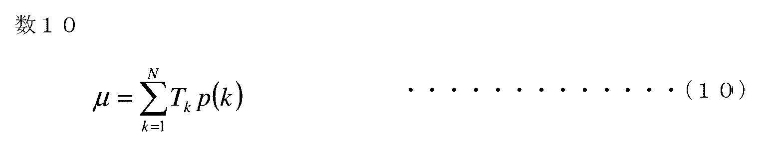
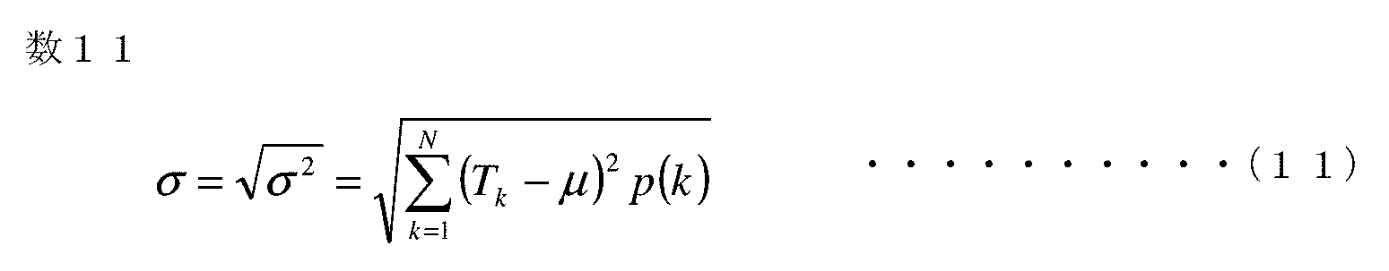
- step 105 the histogram calculation unit 23 expresses the load torque value of the sampling number obtained by the load torque calculation unit 22 as a probability density function. Then, the average value ⁇ and the standard deviation ⁇ of the probability density function with the load torque value Tk as a variable are calculated by the average value calculation unit 23a and the standard deviation calculation unit 23b by the equations (10) and (11), respectively.
- P (k) in the equation is the probability of the load torque value Tk.
- the probability density function is represented by a normal distribution if the variation in load torque value is random. At this time, if the graph is plotted with the horizontal axis as the load torque value and the vertical axis as the probability density, it is represented by the histogram shown in FIG. The probability density of the average value is the highest, and the curve becomes a gentle curve centering on the average value.
- Step 101 to Step 105 the operation from Step 101 to Step 105 is performed to obtain a histogram, and the curve at this time is normal.
- the normal curve storage unit 33, the average value storage unit 33a, and the standard deviation storage unit 33b are stored as a time histogram.
- selection criteria for the normal curve for example, a curve having a normal distribution with a good curve shape and a relatively large average value is selected.
- the normal histogram stored in the normal curve storage unit 33 in this way is a criterion for abnormality determination.
- the abnormality determination unit 24 compares the normal histogram stored in the normal curve storage unit 33 with the histogram obtained by the histogram calculation unit 23 to determine whether there is an abnormality.
- abnormality for example, as shown in FIG. 7, when the average value of the load torque value is shifted to the larger one with respect to the normal histogram, and when there are two or more peaks in the histogram as shown in FIG. It may be the case.
- the configuration is such that the peak location of the histogram is first counted, and when there is one peak location, the Mahalanobis distance determination unit 24a determines, and when there are two or more peak locations, the peak number determination unit 24b determines. It has become.
- the peak position of the histogram can be calculated by a differentiation method.
- the Mahalanobis distance determination unit 24a will be described. As shown in FIG. 7, when the average value of the histogram is larger than the average value in the normal state, there is a possibility that, for example, the wear deterioration of the bearing of the electric motor 7 or the wear deterioration of the mechanical equipment 8 may occur. As shown in FIG. 8, the Mahalanobis distance determination unit 24a calculates the Mahalanobis distance from the normal time with respect to the average value and the standard deviation, and determines that it is abnormal when it is larger than a preset threshold value. For example, the threshold value is calculated by obtaining a maximum deviation 3 ⁇ when a normal curve is determined from a curve measured a plurality of times, for example. Further, by using the past histogram information stored in the histogram storage unit 34 in time series, the trend analysis of the Mahalanobis distance is performed as shown in FIG. It is also possible to monitor the deterioration trend.
- the peak number determination unit 24b will be described. As shown in FIG. 10, when there are two or more peak portions in the histogram, there is a high possibility that a torque abnormality has occurred periodically. For example, in the case of an abnormal gear failure, a periodic load torque may be applied in a period obtained by dividing the rotation frequency by the reduction ratio, resulting in a periodic torque abnormality. As shown in FIG. 11, the peak number determination unit 24b calculates the peak ratio by B / A, where A is the peak value having the largest value and B is the second peak value, and the calculated peak ratio. By setting a threshold value for, periodic torque abnormality can be detected.
- the peak ratio between the peak value having the largest value and the peak value having the second largest value may be calculated. Further, by using the historical histogram information stored in the histogram storage unit 34 in time series, the trend analysis of the peak ratio is performed as shown in FIG. The trend of abnormal occurrence can also be monitored.
- step 107 If it is determined in step 107 that the Mahalanobis distance determination unit 24a or the peak number determination unit 24b of the abnormality determination unit 24 is abnormal, the process proceeds to step 108, and an alarm is output from the alarm output unit 42 with an alarm sound or an abnormal lamp. To do. In general, since the control center where the motor diagnosis device 9 is used is installed and managed in an electric room, a plurality of electric motors 7 and The machine facility 8 can be monitored. Finally, in step 109, the histogram data obtained by the histogram calculation unit 23 is stored in the histogram storage unit 34 of the storage unit 30 in time series, and the process ends. When trend analysis is performed, the data should be saved.
- the load torque behavior is similar if the combination of the same mechanical equipment and the same output electric motor. That is, failure detection accuracy can be improved by simultaneous management of a plurality of facilities instead of individual management.
- an abnormality diagnosis method that focuses on the probability density function of current instead of an abnormality diagnosis based on load torque is also conceivable, a failure in a load facility such as the electric motor 7 or the mechanical facility 8 is easily reflected in the load torque. It is better to focus on the load torque.
- the electric motor diagnosis device of the present invention is naturally applicable to a high-efficiency electric motor.
- the rated rotational speed is higher than that of a general-purpose electric motor, and the amount of work increases and the output of the electric motor increases as the rotational speed increases. For this reason, the current that flows through the motor exceeds the rated torque that is the specification of the motor, and in the worst case, it may cause a failure that leads to burning of the motor.
- the diagnostic monitoring by the load torque of the present invention is also useful from the viewpoint of preventing such a failure.
- the embodiments can be freely combined within the scope of the invention, and the embodiments can be appropriately modified or omitted.
Landscapes
- Engineering & Computer Science (AREA)
- Power Engineering (AREA)
- Physics & Mathematics (AREA)
- General Physics & Mathematics (AREA)
- Control Of Electric Motors In General (AREA)
- Tests Of Circuit Breakers, Generators, And Electric Motors (AREA)
Abstract
Description
実施の形態1.
図1はこの発明の実施の形態1における電動機の診断装置の設置状況を示す概略構成図、図2はこの発明の実施の形態1における電動機の診断装置の論理演算部の構成を示すブロック図、図3はこの発明の実施の形態1における電動機の診断装置の記憶部の構成を示すブロック図、図4はこの発明の実施の形態1における電動機の診断装置のサンプリング速度と忘却係数およびスケールファクタの関係を説明する説明図、図5はこの発明の実施の形態1における電動機の診断装置の動作を説明するフロー図、図6はこの発明の実施の形態1における電動機の診断装置の負荷トルクのヒストグラムを説明する説明図、図7はこの発明の実施の形態1における電動機の診断装置の正常時のヒストグラムよりも異常時のヒストグラムのピーク箇所がずれている場合を説明する説明図、図8はこの発明の実施の形態1における電動機の診断装置のヒストグラムにおけるマハラノビス距離を説明する説明図、図9はこの発明の実施の形態1における電動機の診断装置のマハラノビス距離によるしきい値判定を説明する説明図、図10はこの発明の実施の形態1における電動機の診断装置の正常時のヒストグラムに対して異常時のヒストグラムのピーク箇所が2カ所ある場合を説明する説明図、図11はこの発明の実施の形態1における電動機の診断装置の異常時のヒストグラムの2カ所のピーク箇所のピーク比を説明する説明図、図12はこの発明の実施の形態1における電動機の診断装置のピーク比によるしきい値判定を説明する説明図である。
一般に、電動機7の固定子巻線の温度が上昇すると巻線抵抗値Rsが増えるため、例えば電動機7の製造メーカ等で試験して得られた巻線抵抗値Rsと温度の相関関係を予め定格情報記憶部32に設定しておいて、電圧および電流のサンプリングを行う時の固定子巻線の温度を検出入力して、巻線抵抗値演算部22aで設定された相関関係から巻線抵抗値Rsを精度よく求めることが可能である。なお、巻線抵抗値Rsは検出した電圧および電流から演算して求める方法もあり、巻線抵抗値演算部22aの演算は、上記説明の方法に限定されるものではない。
異常判定部24には、後で詳細に動作説明する異常の状態に応じて異常の有無を判定するマハラノビス距離判定部24aとピーク数判定部24bが設けられている。
また、正常曲線記憶部33には、正常時のヒストグラムの元データである平均値と標準偏差をそれぞれ記憶する平均値記憶部33aと標準偏差記憶部33bが設けられており、ヒストグラム保存部34には、ヒストグラムの元データである平均値と標準偏差をそれぞれ保存する平均値保存部34aと標準偏差保存部34bが設けられている。
ステップ101において、電圧入力部11から二相間分の電圧vuvとvvwがサンプリング速度設定部13で設定されサンプリング速度記憶部31に記憶されているサンプリング速度で入力されるとともに、電流入力部12から二相分の電流iuとivがサンプリング入力される。
dq変換演算部21での演算について説明する。まず、三相電流をdq変換する場合には、三相uvwが平衡している状態では二相分の電流情報だけで十分であるため、電流入力部12から入力した二相分の電流iuとivを使用して、d軸方向の電流idとq軸方向の電流iqを式(1)に示す変換式によって演算する。
負荷トルク演算部22での演算について説明する。負荷トルク演算部22では、dq変換演算部21で演算して求められたdq軸方向の電流id,iqと、予め定格情報入力部14から入力され定格情報記憶部32に記憶されている電動機7の磁極数Ppと、電動機7の固定子巻線のdq軸方向の鎖交磁束φd,φqとによって負荷トルクTeを式(3)によって演算する。


最後に、ステップ109において、ヒストグラム演算部23で求められたヒストグラムのデータを記憶部30のヒストグラム保存部34に時系列で保存して処理を終了する。
なお、トレンド解析を実施した場合には、そのデータも保存しておくとよい。
なお、上記実施の形態1の説明では、入力された電圧および電流をdq変換演算部21でdq軸方向の電圧および電流に変換する場合について説明したが、この変換機能を電圧入力部11および電流入力部12に持たせるように構成されていてもよい。
また、負荷トルクによる異常診断ではなく電流の確率密度関数に着目した異常診断手法も考えられるが、電動機7や機械設備8などの負荷設備の故障は負荷トルクに反映されやすいため、本件発明のように負荷トルクに着目した方がよい。
Claims (4)
- 電動機が接続された主回路からサンプリング入力された電圧および電流を使用して前記電動機の負荷トルクを演算する負荷トルク演算部と、前記負荷トルク演算部で演算されたサンプリング個数の負荷トルクの確率密度関数の平均値と標準偏差を算出してヒストグラム化するヒストグラム演算部と、正常時の負荷トルクのヒストグラムを予め求めて記憶した正常曲線記憶部と、前記正常曲線記憶部に記憶されている正常時のヒストグラムと前記ヒストグラム演算部で求められたヒストグラムを比較して前記電動機の異常の有無を判定する異常判定部とを備えていることを特徴とする電動機の診断装置。
- 前記異常判定部は前記ヒストグラム演算部で求められたヒストグラムのピーク箇所が正常時のピーク箇所からずれているとき、前記ヒストグラム演算部で求められたヒストグラムの平均値と標準偏差に関する正常時からのマハラノビス距離を算出して異常判定することを特徴とする請求項1に記載の電動機の診断装置。
- 前記異常判定部は前記ヒストグラム演算部で求められたヒストグラムにピーク箇所が二個以上あるとき、最も値の大きいピーク値と二番目に値の大きいピーク値との比を算出して異常判定することを特徴とする請求項1に記載の電動機の診断装置。
- 前記異常判定部は保存されている過去のヒストグラム情報を使用してトレンド解析することを特徴とする請求項1から3のいずれか一項に記載の電動機の診断装置。
Priority Applications (4)
| Application Number | Priority Date | Filing Date | Title |
|---|---|---|---|
| PCT/JP2016/071705 WO2018020545A1 (ja) | 2016-07-25 | 2016-07-25 | 電動機の診断装置 |
| EP16910449.4A EP3489700B1 (en) | 2016-07-25 | 2016-07-25 | Electric motor diagnosis device |
| CN201680087608.XA CN109477869B (zh) | 2016-07-25 | 2016-07-25 | 电动机的诊断装置 |
| KR1020197000145A KR102104117B1 (ko) | 2016-07-25 | 2016-07-25 | 전동기의 진단 장치 |
Applications Claiming Priority (1)
| Application Number | Priority Date | Filing Date | Title |
|---|---|---|---|
| PCT/JP2016/071705 WO2018020545A1 (ja) | 2016-07-25 | 2016-07-25 | 電動機の診断装置 |
Publications (1)
| Publication Number | Publication Date |
|---|---|
| WO2018020545A1 true WO2018020545A1 (ja) | 2018-02-01 |
Family
ID=61017415
Family Applications (1)
| Application Number | Title | Priority Date | Filing Date |
|---|---|---|---|
| PCT/JP2016/071705 Ceased WO2018020545A1 (ja) | 2016-07-25 | 2016-07-25 | 電動機の診断装置 |
Country Status (4)
| Country | Link |
|---|---|
| EP (1) | EP3489700B1 (ja) |
| KR (1) | KR102104117B1 (ja) |
| CN (1) | CN109477869B (ja) |
| WO (1) | WO2018020545A1 (ja) |
Cited By (5)
| Publication number | Priority date | Publication date | Assignee | Title |
|---|---|---|---|---|
| CN108445393A (zh) * | 2018-05-02 | 2018-08-24 | 湖南大学 | 一种永磁同步电机故障检测方法和系统 |
| WO2020137362A1 (ja) * | 2018-12-26 | 2020-07-02 | 日本電産株式会社 | 判定装置、モータ装置及びプログラム |
| JP2021012199A (ja) * | 2019-07-08 | 2021-02-04 | テクトロニクス・インコーポレイテッドTektronix,Inc. | 試験測定装置及び被試験デバイスの性能測定方法 |
| WO2022024421A1 (ja) * | 2020-07-31 | 2022-02-03 | 三菱重工業株式会社 | 回転機械の診断装置、診断方法及び診断プログラム |
| WO2022024422A1 (ja) * | 2020-07-31 | 2022-02-03 | 三菱重工業株式会社 | 回転機械の診断装置、診断方法及び診断プログラム |
Families Citing this family (5)
| Publication number | Priority date | Publication date | Assignee | Title |
|---|---|---|---|---|
| JP7191807B2 (ja) * | 2019-11-29 | 2022-12-19 | 株式会社日立製作所 | 診断装置および診断方法 |
| DE112020007232T5 (de) * | 2020-05-25 | 2023-03-16 | Mitsubishi Electric Corporation | Motor-diagnosevorrichtung |
| TWI763287B (zh) * | 2021-01-29 | 2022-05-01 | 凌華科技股份有限公司 | 具有偵錯功能之馬達命令輸出模組及馬達命令偵錯方法 |
| JP7643124B2 (ja) * | 2021-03-23 | 2025-03-11 | 富士電機株式会社 | モータの異常診断装置、異常診断方法及び異常診断プログラム |
| CN114545117A (zh) * | 2022-01-24 | 2022-05-27 | 东华大学 | 基于拟合概率密度函数的工业机器人关节异常检测方法 |
Citations (7)
| Publication number | Priority date | Publication date | Assignee | Title |
|---|---|---|---|---|
| JP2002010681A (ja) * | 2000-06-16 | 2002-01-11 | Aisin Seiki Co Ltd | モータ駆動装置 |
| JP2003070287A (ja) * | 2001-08-28 | 2003-03-07 | Yaskawa Electric Corp | 診断機能を備えたモータ制御装置 |
| JP2005012879A (ja) * | 2003-06-17 | 2005-01-13 | Yaskawa Electric Corp | モータ制御装置 |
| JP2006158031A (ja) * | 2004-11-26 | 2006-06-15 | Yaskawa Electric Corp | モータ制御装置およびその制御方法 |
| JP2011257362A (ja) * | 2010-06-11 | 2011-12-22 | Takada Corp | 回転機械系の異常診断方法 |
| JP2013106470A (ja) * | 2011-11-15 | 2013-05-30 | Tokyo Keiki Inc | モータの異常診断装置 |
| WO2016103909A1 (ja) * | 2014-12-26 | 2016-06-30 | 三菱電機株式会社 | 電動機の診断装置 |
Family Cites Families (9)
| Publication number | Priority date | Publication date | Assignee | Title |
|---|---|---|---|---|
| TR199600527A2 (xx) | 1996-06-24 | 1998-01-21 | Ar�El�K A.�. | Elektrik motorlar� i�in model bazl� hata tespit ve te�his sistemi. |
| US6262550B1 (en) * | 1999-12-17 | 2001-07-17 | General Electric Company | Electrical motor monitoring system and method |
| US7254514B2 (en) * | 2005-05-12 | 2007-08-07 | General Electric Company | Method and system for predicting remaining life for motors featuring on-line insulation condition monitor |
| KR101224435B1 (ko) * | 2011-06-20 | 2013-01-22 | 현대엘리베이터주식회사 | 전동기의 속도 및 구동 모드에 대한 실부하 측정장치 및 그 방법 |
| JP5991042B2 (ja) * | 2011-06-29 | 2016-09-14 | Jfeスチール株式会社 | 異常監視システムおよび異常監視方法 |
| PL3068273T3 (pl) * | 2013-11-12 | 2020-07-27 | Koninklijke Philips N.V. | Młynek do kawy i sposób mielenia kawy |
| CN104215905A (zh) * | 2014-09-05 | 2014-12-17 | 浙江工业大学 | 一种基于马田系统和Box-Cox变换的电机故障诊断方法 |
| JP6238928B2 (ja) * | 2015-04-03 | 2017-11-29 | 三菱電機株式会社 | 電動機の診断装置 |
| CN105403834B (zh) * | 2015-12-22 | 2019-04-12 | 华北电力大学 | 一种发电机动态状态估计方法 |
-
2016
- 2016-07-25 EP EP16910449.4A patent/EP3489700B1/en active Active
- 2016-07-25 KR KR1020197000145A patent/KR102104117B1/ko active Active
- 2016-07-25 WO PCT/JP2016/071705 patent/WO2018020545A1/ja not_active Ceased
- 2016-07-25 CN CN201680087608.XA patent/CN109477869B/zh active Active
Patent Citations (7)
| Publication number | Priority date | Publication date | Assignee | Title |
|---|---|---|---|---|
| JP2002010681A (ja) * | 2000-06-16 | 2002-01-11 | Aisin Seiki Co Ltd | モータ駆動装置 |
| JP2003070287A (ja) * | 2001-08-28 | 2003-03-07 | Yaskawa Electric Corp | 診断機能を備えたモータ制御装置 |
| JP2005012879A (ja) * | 2003-06-17 | 2005-01-13 | Yaskawa Electric Corp | モータ制御装置 |
| JP2006158031A (ja) * | 2004-11-26 | 2006-06-15 | Yaskawa Electric Corp | モータ制御装置およびその制御方法 |
| JP2011257362A (ja) * | 2010-06-11 | 2011-12-22 | Takada Corp | 回転機械系の異常診断方法 |
| JP2013106470A (ja) * | 2011-11-15 | 2013-05-30 | Tokyo Keiki Inc | モータの異常診断装置 |
| WO2016103909A1 (ja) * | 2014-12-26 | 2016-06-30 | 三菱電機株式会社 | 電動機の診断装置 |
Cited By (12)
| Publication number | Priority date | Publication date | Assignee | Title |
|---|---|---|---|---|
| CN108445393A (zh) * | 2018-05-02 | 2018-08-24 | 湖南大学 | 一种永磁同步电机故障检测方法和系统 |
| CN108445393B (zh) * | 2018-05-02 | 2019-10-29 | 湖南大学 | 一种永磁同步电机故障检测方法和系统 |
| WO2020137362A1 (ja) * | 2018-12-26 | 2020-07-02 | 日本電産株式会社 | 判定装置、モータ装置及びプログラム |
| JP2021012199A (ja) * | 2019-07-08 | 2021-02-04 | テクトロニクス・インコーポレイテッドTektronix,Inc. | 試験測定装置及び被試験デバイスの性能測定方法 |
| US12088223B2 (en) | 2019-07-08 | 2024-09-10 | Tektronix, Inc. | DQ0 and inverse DQ0 transformation for three-phase inverter, motor and drive design |
| JP7642330B2 (ja) | 2019-07-08 | 2025-03-10 | テクトロニクス・インコーポレイテッド | 試験測定装置及び被試験デバイスの性能測定方法 |
| WO2022024421A1 (ja) * | 2020-07-31 | 2022-02-03 | 三菱重工業株式会社 | 回転機械の診断装置、診断方法及び診断プログラム |
| WO2022024422A1 (ja) * | 2020-07-31 | 2022-02-03 | 三菱重工業株式会社 | 回転機械の診断装置、診断方法及び診断プログラム |
| JP2022026633A (ja) * | 2020-07-31 | 2022-02-10 | 三菱重工業株式会社 | 回転機械の診断装置、診断方法及び診断プログラム |
| JP2022026620A (ja) * | 2020-07-31 | 2022-02-10 | 三菱重工業株式会社 | 回転機械の診断装置、診断方法及び診断プログラム |
| JP7451340B2 (ja) | 2020-07-31 | 2024-03-18 | 三菱重工業株式会社 | 回転機械の診断装置、診断方法及び診断プログラム |
| JP7453875B2 (ja) | 2020-07-31 | 2024-03-21 | 三菱重工業株式会社 | 回転機械の診断装置、診断方法及び診断プログラム |
Also Published As
| Publication number | Publication date |
|---|---|
| CN109477869B (zh) | 2021-02-26 |
| EP3489700B1 (en) | 2020-08-19 |
| CN109477869A (zh) | 2019-03-15 |
| KR20190014074A (ko) | 2019-02-11 |
| EP3489700A4 (en) | 2019-07-31 |
| EP3489700A1 (en) | 2019-05-29 |
| KR102104117B1 (ko) | 2020-04-23 |
Similar Documents
| Publication | Publication Date | Title |
|---|---|---|
| JP6238928B2 (ja) | 電動機の診断装置 | |
| WO2018020545A1 (ja) | 電動機の診断装置 | |
| KR102427372B1 (ko) | 이상 진단 장치, 이상 진단 방법 및 이상 진단 시스템 | |
| CN107155353B (zh) | 电动机的诊断装置 | |
| EP3054307A1 (en) | Stator fault detection and diagnosis | |
| JP6316510B1 (ja) | 電動機の診断装置 | |
| KR101823140B1 (ko) | 인버터 고장 진단 방법 및 그 장치 | |
| JP2005251185A (ja) | 電気設備診断システム | |
| JP2016195524A (ja) | 電動機の診断装置 | |
| KR20230154992A (ko) | 이상 진단 장치 및 이상 진단 방법 | |
| EP3376242B1 (en) | Electric motor diagnosis device | |
| JPWO2016103909A1 (ja) | 電動機の診断装置 | |
| US10444288B2 (en) | Abnormality diagnosing device and abnormality diagnosing method | |
| CN116990683B (zh) | 一种基于电变量的驱动电机堵转检测系统及检测方法 | |
| WO2016151708A1 (ja) | 電機品の故障検出装置および故障検出方法 | |
| JP5985158B2 (ja) | 電気設備の良否診断システム | |
| JP7643124B2 (ja) | モータの異常診断装置、異常診断方法及び異常診断プログラム | |
| JP6113384B1 (ja) | 電動機の診断装置 | |
| JP6457583B2 (ja) | 異常診断装置および異常診断方法 | |
| Araújo et al. | A Digital Twin Approach to Smart Monitoring and Fault Diagnosis | |
| JP6867812B2 (ja) | 回転機の短絡診断装置および回転機の短絡診断方法 | |
| US12174256B2 (en) | Device monitoring device and device monitoring method | |
| JP2008011622A (ja) | インバータ装置とその交流電動機診断、及び診断結果表示方法 | |
| Zhang et al. | A Model-Based Method for Fault Detection and Isolation of Electric Drive Systems | |
| CA3158441A1 (en) | Systems and methods for providing voltage-less electrical signature analysis for fault protection |
Legal Events
| Date | Code | Title | Description |
|---|---|---|---|
| 121 | Ep: the epo has been informed by wipo that ep was designated in this application |
Ref document number: 16910449 Country of ref document: EP Kind code of ref document: A1 |
|
| ENP | Entry into the national phase |
Ref document number: 20197000145 Country of ref document: KR Kind code of ref document: A |
|
| NENP | Non-entry into the national phase |
Ref country code: DE |
|
| ENP | Entry into the national phase |
Ref document number: 2016910449 Country of ref document: EP Effective date: 20190225 |
|
| NENP | Non-entry into the national phase |
Ref country code: JP |