WO2018020549A1 - 半導体装置 - Google Patents
半導体装置 Download PDFInfo
- Publication number
- WO2018020549A1 WO2018020549A1 PCT/JP2016/071721 JP2016071721W WO2018020549A1 WO 2018020549 A1 WO2018020549 A1 WO 2018020549A1 JP 2016071721 W JP2016071721 W JP 2016071721W WO 2018020549 A1 WO2018020549 A1 WO 2018020549A1
- Authority
- WO
- WIPO (PCT)
- Prior art keywords
- semiconductor device
- gate fingers
- base substrate
- semiconductor
- arrangement direction
- Prior art date
- Legal status (The legal status is an assumption and is not a legal conclusion. Google has not performed a legal analysis and makes no representation as to the accuracy of the status listed.)
- Ceased
Links
Images




Classifications
-
- H—ELECTRICITY
- H10—SEMICONDUCTOR DEVICES; ELECTRIC SOLID-STATE DEVICES NOT OTHERWISE PROVIDED FOR
- H10D—INORGANIC ELECTRIC SEMICONDUCTOR DEVICES
- H10D64/00—Electrodes of devices having potential barriers
- H10D64/20—Electrodes characterised by their shapes, relative sizes or dispositions
- H10D64/23—Electrodes carrying the current to be rectified, amplified, oscillated or switched, e.g. sources, drains, anodes or cathodes
- H10D64/251—Source or drain electrodes for field-effect devices
- H10D64/257—Source or drain electrodes for field-effect devices for lateral devices wherein the source or drain electrodes are characterised by top-view geometrical layouts, e.g. interdigitated, semi-circular, annular or L-shaped electrodes
-
- H—ELECTRICITY
- H10—SEMICONDUCTOR DEVICES; ELECTRIC SOLID-STATE DEVICES NOT OTHERWISE PROVIDED FOR
- H10D—INORGANIC ELECTRIC SEMICONDUCTOR DEVICES
- H10D30/00—Field-effect transistors [FET]
- H10D30/40—FETs having zero-dimensional [0D], one-dimensional [1D] or two-dimensional [2D] charge carrier gas channels
- H10D30/47—FETs having zero-dimensional [0D], one-dimensional [1D] or two-dimensional [2D] charge carrier gas channels having two-dimensional [2D] charge carrier gas channels, e.g. nanoribbon FETs or high electron mobility transistors [HEMT]
- H10D30/471—High electron mobility transistors [HEMT] or high hole mobility transistors [HHMT]
- H10D30/475—High electron mobility transistors [HEMT] or high hole mobility transistors [HHMT] having wider bandgap layer formed on top of lower bandgap active layer, e.g. undoped barrier HEMTs such as i-AlGaN/GaN HEMTs
-
- H—ELECTRICITY
- H10—SEMICONDUCTOR DEVICES; ELECTRIC SOLID-STATE DEVICES NOT OTHERWISE PROVIDED FOR
- H10D—INORGANIC ELECTRIC SEMICONDUCTOR DEVICES
- H10D62/00—Semiconductor bodies, or regions thereof, of devices having potential barriers
- H10D62/80—Semiconductor bodies, or regions thereof, of devices having potential barriers characterised by the materials
- H10D62/82—Heterojunctions
- H10D62/824—Heterojunctions comprising only Group III-V materials heterojunctions, e.g. GaN/AlGaN heterojunctions
-
- H—ELECTRICITY
- H10—SEMICONDUCTOR DEVICES; ELECTRIC SOLID-STATE DEVICES NOT OTHERWISE PROVIDED FOR
- H10D—INORGANIC ELECTRIC SEMICONDUCTOR DEVICES
- H10D64/00—Electrodes of devices having potential barriers
- H10D64/20—Electrodes characterised by their shapes, relative sizes or dispositions
- H10D64/27—Electrodes not carrying the current to be rectified, amplified, oscillated or switched, e.g. gates
- H10D64/311—Gate electrodes for field-effect devices
- H10D64/411—Gate electrodes for field-effect devices for FETs
-
- H—ELECTRICITY
- H10—SEMICONDUCTOR DEVICES; ELECTRIC SOLID-STATE DEVICES NOT OTHERWISE PROVIDED FOR
- H10W—GENERIC PACKAGES, INTERCONNECTIONS, CONNECTORS OR OTHER CONSTRUCTIONAL DETAILS OF DEVICES COVERED BY CLASS H10
- H10W20/00—Interconnections in chips, wafers or substrates
- H10W20/40—Interconnections external to wafers or substrates, e.g. back-end-of-line [BEOL] metallisations or vias connecting to gate electrodes
- H10W20/41—Interconnections external to wafers or substrates, e.g. back-end-of-line [BEOL] metallisations or vias connecting to gate electrodes characterised by their conductive parts
- H10W20/427—Power or ground buses
-
- H—ELECTRICITY
- H10—SEMICONDUCTOR DEVICES; ELECTRIC SOLID-STATE DEVICES NOT OTHERWISE PROVIDED FOR
- H10W—GENERIC PACKAGES, INTERCONNECTIONS, CONNECTORS OR OTHER CONSTRUCTIONAL DETAILS OF DEVICES COVERED BY CLASS H10
- H10W20/00—Interconnections in chips, wafers or substrates
- H10W20/40—Interconnections external to wafers or substrates, e.g. back-end-of-line [BEOL] metallisations or vias connecting to gate electrodes
- H10W20/482—Interconnections external to wafers or substrates, e.g. back-end-of-line [BEOL] metallisations or vias connecting to gate electrodes for individual devices provided for in groups H10D8/00 - H10D48/00, e.g. for power transistors
- H10W20/483—Interconnections over air gaps, e.g. air bridges
-
- H—ELECTRICITY
- H10—SEMICONDUCTOR DEVICES; ELECTRIC SOLID-STATE DEVICES NOT OTHERWISE PROVIDED FOR
- H10D—INORGANIC ELECTRIC SEMICONDUCTOR DEVICES
- H10D62/00—Semiconductor bodies, or regions thereof, of devices having potential barriers
- H10D62/80—Semiconductor bodies, or regions thereof, of devices having potential barriers characterised by the materials
- H10D62/85—Semiconductor bodies, or regions thereof, of devices having potential barriers characterised by the materials being Group III-V materials, e.g. GaAs
- H10D62/8503—Nitride Group III-V materials, e.g. AlN or GaN
-
- H—ELECTRICITY
- H10—SEMICONDUCTOR DEVICES; ELECTRIC SOLID-STATE DEVICES NOT OTHERWISE PROVIDED FOR
- H10D—INORGANIC ELECTRIC SEMICONDUCTOR DEVICES
- H10D64/00—Electrodes of devices having potential barriers
- H10D64/20—Electrodes characterised by their shapes, relative sizes or dispositions
- H10D64/23—Electrodes carrying the current to be rectified, amplified, oscillated or switched, e.g. sources, drains, anodes or cathodes
- H10D64/251—Source or drain electrodes for field-effect devices
- H10D64/256—Source or drain electrodes for field-effect devices for lateral devices wherein the source or drain electrodes are recessed in semiconductor bodies
Definitions
- the present invention relates to a semiconductor device having a transistor structure.
- transistors having a nitride semiconductor such as GaN (gallium nitride) or AlGaN (aluminum gallium nitride) are widely used as high-frequency power semiconductor devices such as microwaves.
- GaN is superior in terms of breakdown voltage and saturation electron velocity over other semiconductor materials such as GaAs (gallium arsenide) and Si (silicon).
- GaN is used as a constituent material for power semiconductor devices such as HEMT (High Electron Mobility Transistor).
- HEMT High Electron Mobility Transistor
- a transistor structure called a multi-fingered structure in which a plurality of transistor elements are arranged in parallel is also widely used.
- a HEMT having a multi-finger structure disclosed in Non-Patent Document 1 below includes a GaN buffer layer formed on a substrate, an AlGaN barrier layer formed on the GaN buffer layer, and the AlGaN barrier layer.
- a plurality of finger-shaped gate electrodes (hereinafter also referred to as “gate fingers”) arranged in a predetermined direction above, and a drain electrode and a source electrode formed at positions sandwiching each gate finger. is there.
- heat dissipation can be improved by increasing the interval (pitch) between the gate fingers. That is, since the end of each gate finger on the drain electrode side serves as a heat source, it is possible to reduce the overlap of heat distribution generated by each of the plurality of gate fingers by widening the gap between the gate fingers. Thereby, the device temperature can be reduced.
- an object of the present invention is to provide a semiconductor device capable of improving heat dissipation without widening the gap between gate fingers as much as possible.
- a semiconductor device includes a base substrate having first and second main surfaces facing each other, a semiconductor layer formed on the first main surface, and a predetermined thickness on the semiconductor layer.
- a group of gate fingers each disposed in a region between the drain electrode and the source electrode, wherein the group of gate fingers are respectively disposed at positions shifted from each other in the extending direction.
- a plurality of gate fingers are provided.
- FIG. 2 is a schematic cross-sectional view of a unit transistor structure that constitutes a part of the semiconductor device shown in FIG. 1. It is a graph which shows the calculation result of the thermal resistance by a 45 degree method. It is a top view which shows roughly an example of the layout of the semiconductor device which has the conventional multi-finger structure.
- FIG. 5A is a diagram showing an example of a heat distribution photograph obtained by measuring a multi-finger structure of an operating HEMT using an IR (infrared) microscope
- FIG. 5B is a graph showing a temperature distribution. .
- FIG. 1 is a plan view showing a layout of a semiconductor device 1 having a multi-finger structure according to the first embodiment of the present invention.
- FIG. 2 is a schematic cross-sectional view of a unit transistor structure constituting a part of the semiconductor device 1 shown in FIG. FIG. 2 shows a cross section parallel to the XZ plane including the X axis and the Z axis.
- the semiconductor device 1 includes a base substrate 4 such as a silicon (Si) substrate, a silicon carbide (SiC) substrate, or a sapphire substrate, and a front surface (first main surface) of the base substrate 4. And a stacked body 5 composed of a plurality of compound semiconductor layers stacked on the surface). As shown in FIG. 1, the semiconductor device 1 connects the conductor pattern 10 including the drain electrodes 11 to 15, the ground connection conductors 20 A and 20 B, the source electrodes 21 to 24, and the source electrodes 21 and 22.
- a base substrate 4 such as a silicon (Si) substrate, a silicon carbide (SiC) substrate, or a sapphire substrate
- a stacked body 5 composed of a plurality of compound semiconductor layers stacked on the surface.
- the semiconductor device 1 connects the conductor pattern 10 including the drain electrodes 11 to 15, the ground connection conductors 20 A and 20 B, the source electrodes 21 to 24, and the source electrodes 21 and 22.
- Air bridges 25 and 26 which are wiring layers electrically connected to the conductor 20A
- air bridges 27 and 28 which are wiring layers electrically connecting the source electrodes 23 and 24 to the connection conductor 20B, and gate fingers 31 to 38.
- a conductor pattern 30 including These conductor patterns 10 and 30, source electrodes 21 to 24, connection conductors 20A and 20B, and air bridges 25 to 28 are formed on the laminate 5 shown in FIG.
- the gate fingers 31 to 38 are covered with a protective film 8 composed of a lower protective film 8A and an upper protective film 8B as shown in FIG.
- the protective film 8 may be made of an insulating film such as an aluminum oxide film (Al 2 O 3 film) or a silicon nitride film (SiN film).
- Al 2 O 3 film aluminum oxide film
- SiN film silicon nitride film
- the semiconductor device 1 of the present embodiment is a high frequency device having a HEMT (High Electron Mobility Transistor) structure using a group III nitride semiconductor.
- the group III nitride semiconductor is a compound semiconductor containing a group III element such as Ga (gallium), In (indium), or Al (aluminum) and N (nitrogen).
- GaN (gallium nitride), AlN (aluminum nitride), InN (indium nitride), AlGaN (aluminum gallium nitride) or InAlN (indium aluminum nitride) can be used as the group III nitride semiconductor.
- a channel layer 6 formed on the base substrate 4 and a barrier layer 7 heterojunction with the channel layer 6.
- a heterojunction interface is formed between the channel layer 6 and the barrier layer 7. Due to the presence of the heterojunction interface, a two-dimensional electron gas is induced inside the channel layer 6.
- a GaN layer can be formed as the channel layer 6, and an AlGaN (aluminum gallium nitride) layer or an InAlN (indium aluminum nitride) layer can be formed as the barrier layer 7, for example.
- the barrier layer 7 is not limited to a single layer, and may be composed of a plurality of layers such as an AlGaN layer and an InAlN layer.
- a spacer layer such as AlN may be provided between the channel layer 6 and the barrier layer 7 in order to control the heterojunction interface.
- the channel layer 6, the barrier layer 7, and the spacer layer can be formed by MOCVD (Metal Organic Chemical Vapor Deposition) or MBE (Molecular Beam Epitaxy).
- the conductor pattern 30 has a signal input connection end 39 to be electrically connected to the input circuit 3 for transmitting a high-frequency signal, and a branch from the connection end 39 to the X-axis positive direction.
- a wiring portion 30a extending in the negative direction
- a group of gate fingers 31 extending in the positive Y-axis direction from these wiring portions 30a and 30b.
- the total number of gate fingers 31 to 38 is 8, but the number is not limited to this number.
- Each of the gate fingers 31 to 38 is a gate electrode having a linear finger shape extending in the Y-axis positive direction (predetermined extending direction). These gate fingers 31 to 38 have the same dimensions and are arranged at a constant interval (pitch) Lg in the X-axis direction (predetermined arrangement direction).
- the conductor pattern 30 can be formed using a metal material such as Ni (nickel) or Au (gold), for example, by vapor deposition or dry etching.
- the wiring portions 30a and 30b, the gate fingers 31 to 38, and the connection end 39 may be formed simultaneously in the same film forming process, or may be formed individually in different film forming processes. Also good. At least the gate fingers 31 to 38 are formed so as to form a Schottky junction with the barrier layer 7 of FIG.
- the conductor pattern 10 shown in FIG. 1 has a signal output connection end 19 to be electrically connected to the output circuit 2 for transmitting a high-frequency signal, and the connection end 19 is electrically connected.
- the drain electrodes 11, 12, 13, 14, and 15 are included.
- source electrodes 21, 22, 23, 24, and 25 are provided at positions corresponding to the drain electrodes 11, 12, 13, 14, and 15, respectively.
- the drain electrodes 11 to 15 and the source electrodes 21 to 25 are arranged so as to constitute an electrode pattern in which the source electrodes and the drain electrodes are alternately arranged along the X-axis direction. .
- Each of the gate fingers 31 to 38 is disposed in each region between the alternately arranged source electrodes and drain electrodes. Therefore, in this embodiment, eight unit transistor structures are formed.
- the conductor pattern 10, the source electrodes 21 to 24, and the connection conductors 20A and 20B can be formed using a metal material such as Ti (titanium) or Al (aluminum), for example, by vapor deposition or dry etching.
- the conductor pattern 10, the source electrodes 21 to 24, and the connection conductors 20A and 20B may be simultaneously formed in the same film forming process, or may be formed individually in different film forming processes. Good.
- At least the source electrodes 21 to 24 and the drain electrodes 11 to 15 are formed so as to be in ohmic contact with the barrier layer 7 of FIG.
- connection conductor 20A is electrically connected to a grounding via conductor 29A that penetrates the multilayer body 5 and the base substrate 4 of FIG. 2 in the thickness direction (Z-axis direction) of the base substrate 4.
- connection conductor 20B is electrically connected to a ground via conductor 29B that penetrates the multilayer body 5 and the base substrate 4 in the thickness direction.
- the via conductors 29A and 29B are connected to a ground electrode (not shown) formed on the back surface (second main surface) of the base substrate 4 and are grounded.
- the gate fingers 31 to 38 include gate fingers 31, 33, 36, 38 arranged at an upper position, and gate fingers 32, 34, 35, 37 arranged at a lower position. 2 minutes.
- the gate fingers 31, 33, 36, and 38 arranged above are arranged in a row in the X-axis direction, and the other gate fingers 32, 34, 35, and 37 arranged below are also arranged in a row in the X-axis direction. It is arranged.
- the gate fingers 31, 33, 36, and 38 disposed above and the gate fingers 32, 34, 35, and 37 disposed below are in the Y-axis direction (that is, the extending direction of the gate fingers 31 to 38). ) At positions shifted from each other.
- the gate fingers 31 to 38 of the present embodiment are arranged at positions that are staggered in the vertical direction in the Y-axis direction.
- the gate fingers 31 to 38 are arranged such that the positions of the adjacent gate fingers via the source electrode or the drain electrode are shifted from each other in the Y-axis direction.
- the drain electrodes 11 to 15 and the source electrodes 21 to 24 have a substantially parallelogram shape in accordance with the arrangement of the gate fingers 31 to 38.
- the wiring portions 30a and 30b have a waveform shape that is bent in accordance with the arrangement of the gate fingers 31 to 38.
- the wiring portion for connecting the drain electrodes 11 to 15 to the connection end portion 19 also has a waveform shape as shown in FIG.
- the shape of the inner edges of the connection conductors 20A and 20B also has a waveform shape in accordance with the shape of the wiring portions 30a and 30b.
- the gate fingers 31 to 38 When the gate fingers 31 to 38 are arranged in this way, the X axis between the gate fingers 31, 33, 36, 38 disposed above and the gate fingers 32, 34, 35, 37 disposed below.
- the length Wc of the overlapping range when viewed from the direction is reduced. Thereby, the spatial overlap of the heat distribution generated in the gate fingers 31 to 38 can be reduced. Therefore, compared with the conventional multi-finger structure, the multi-finger structure of the present embodiment can suppress an increase in thermal resistance.
- FIG. 3 is a graph showing the calculation result of the thermal resistance by the 45 degree method.
- the 45-degree method is a technique for calculating a one-dimensional thermal resistance when it is assumed that heat is diffused from the heat source at the end of each gate finger toward the base substrate 4 at an angle of 45 degrees.
- the horizontal axis of the graph in FIG. 3 indicates the length Wc (unit: micrometer) of the overlapping range, and the vertical axis of the graph indicates the thermal resistance Rth (unit: K / W).
- the gate finger interval (Lg) is 20 ⁇ m
- the number of gate fingers is 8
- the gate width of each gate finger is 50 ⁇ m
- the gate length of each gate finger is 0.15 ⁇ m
- an SiC substrate The thermal conductivity of SiC: 350 W / (m ⁇ K)
- FIG. 4 is a plan view schematically showing an example of a layout of a semiconductor device 100 having a conventional multi-finger structure.
- the semiconductor device 100 has a HEMT structure using GaN.
- the semiconductor device 100 includes a conductor pattern 110 including drain electrodes 111 to 115 arranged in a horizontal row, ground connection conductors 120A and 120B, and source electrodes 121 arranged in a horizontal row.
- a conductor pattern 110 including drain electrodes 111 to 115 arranged in a horizontal row, ground connection conductors 120A and 120B, and source electrodes 121 arranged in a horizontal row.
- air bridges 125 and 126 which are wiring layers electrically connecting the source electrodes 121 and 122 to the connection conductor 120A, and air which is wiring layers electrically connecting the source electrodes 123 and 124 to the connection conductor 120B.
- the bridges 127 and 128 and a conductor pattern 130 including gate fingers 131 to 138 arranged in a horizontal row are configured.
- the conductor pattern 110 has a connection end 119 to be connected to an output circuit (not shown), and the conductor pattern 130 has a connection end 139 to be connected to an input circuit (not shown). . Furthermore, the gate fingers 131 to 138 are arranged at a constant interval Lg1 in the lateral direction.
- the gate fingers 131 to 138 overlap in the range of the length Wc1 when viewed from their arrangement direction (lateral direction).
- a point Pt shown in the graph of FIG. 3 corresponds to this length Wc1. Therefore, it can be seen that the multi-finger structure of the present embodiment has a structure in which the spatial overlap of heat distribution is reduced and the thermal resistance can be reduced as compared with the conventional multi-finger structure.
- FIG. 5A is a diagram showing an example of a heat distribution photograph obtained by measuring a conventional multi-finger structure of an HEMT using an IR (infrared) microscope.
- FIG. 5B is a graph showing the temperature distribution along the broken line CS in FIG. 5A.
- the horizontal axis of the graph of FIG. 5B indicates the distance (unit: micrometer) from the reference position, and the vertical axis of the graph indicates the device temperature (unit: ° C.).
- FIGS. 5A and 5B it can be seen that a heat source is generated in each gate finger.
- the temperature of the gate finger located in the center is higher than that of the gate fingers located on the side, it can be seen that there is an overlap of heat distribution between the gate fingers. In order to reduce the device temperature, it is necessary to minimize the spatial overlap of the heat distribution between the gate fingers.
- the semiconductor device 1 of the present embodiment can improve heat dissipation without increasing the distance Lg between the gate fingers 31 to 38 as compared with the conventional multi-finger structure. Therefore, the semiconductor device 1 can be easily downsized. Further, since it is not necessary to increase the size of the drain electrodes 11 to 15 in the X-axis direction, there is an advantage that heat dissipation can be improved without increasing the parasitic capacitance caused by the drain electrodes 11 to 15. is there.
- the semiconductor device 1 is used as a power amplifier as an internal matching FET (IM-FET: Internal Matching-Field Effect Transistor) or as a part of a monolithic microwave integrated circuit (MMIC: Monolithic Microwave Integrated Circuit). It can be used.
- IM-FET Internal Matching-Field Effect Transistor
- MMIC Monolithic Microwave Integrated Circuit
- FIG. 6 is a plan view showing a layout of a multi-fingered semiconductor device 1A according to the second embodiment of the present invention.
- the semiconductor device 1A of the present embodiment is configured to have a total of four grounding via conductors 29A, 29B, 29C, and 29D. That is, the semiconductor device 1A has the same configuration as that of the semiconductor device 1 of the first embodiment. Further, as shown in FIG. 6, the connection conductors 20C and 20D, the air bridges 25B, 26B, 27B, and 28B, and vias Conductors 29C and 29D are provided.
- connection conductor 20C As shown in FIG. 6, the ends of the source electrodes 21, 22 on the Y axis positive direction side are electrically connected to the connection conductor 20C by air bridges 25B, 26B made of a conductive material.
- the air bridges 25 ⁇ / b> B and 26 ⁇ / b> B are formed so as to straddle the wiring portion so as not to contact the wiring portion of the conductor pattern 10.
- the connection conductor 20 ⁇ / b> C is electrically connected to a grounding via conductor 29 ⁇ / b> C that penetrates the multilayer body 5 and the base substrate 4 of FIG. 2 in the thickness direction of the base substrate 4.
- connection conductor 20D is electrically connected to a ground via conductor 29D that penetrates the multilayer body 5 and the base substrate 4 in the thickness direction.
- the via conductors 29 ⁇ / b> C and 29 ⁇ / b> D described above are connected to a ground electrode (not shown) formed on the back surface (second main surface) of the base substrate 4 and are grounded.
- the shape of the inner edge of the connection conductors 20 ⁇ / b> C and 20 ⁇ / b> D has a waveform shape corresponding to the waveform shape of the wiring portion of the conductor pattern 10.
- the semiconductor device 1A of the second embodiment has the same configuration as that of the first embodiment, and thus can achieve the same effects as those of the first embodiment.
- the semiconductor device 1A of the second embodiment since the number of via conductors 29A to 29D for grounding is greater in the present embodiment than in the first embodiment, the source inductance can be reduced and the gain can be improved. Therefore, the semiconductor device 1A of the second embodiment has a structure suitable for a higher frequency band than the first embodiment.
- FIG. 7 is a plan view showing a layout of a multi-fingered semiconductor device 1B according to the third embodiment of the present invention.
- the semiconductor device 1B includes a conductor pattern 40 including drain electrodes 41 to 45, connection conductors 50A, 50B, 50C, and 50D for grounding, source electrodes 51 to 54, and source electrodes 51 and 52.
- Air bridges 55, 56, 55B, and 56B which are wiring layers that electrically connect the connection electrodes 50A and 50C, and air bridges that are wiring layers that electrically connect the source electrodes 53 and 54 to the connection conductors 50B and 50D.
- conductor patterns 40, 60, source electrodes 51 to 54, connection conductors 50A, 50B, 50C, 50D and air bridges 55, 56, 55B, 56B, 57, 58, 57B, 58B are the same as in the first embodiment. 2 is formed on the laminate 5 shown in FIG.
- the conductor pattern 60 branches from the connection end 69 for signal input to be electrically connected to the input circuit 3 for transmitting a high-frequency signal, and rotates clockwise with respect to the positive direction of the Y axis.
- an inclined wiring portion 60a extending in an oblique direction inclined at an angle of less than 90 °, and an inclined portion branched from the connection end 69 and inclined at an angle of less than 90 ° counterclockwise with respect to the positive Y-axis direction. It has an inclined wiring portion 60b extending in the direction, and a group of gate fingers 61 to 68 extending from these inclined wiring portions 60a and 60b in the positive Y-axis direction.
- the total number of gate fingers 61 to 68 is 8, but the number is not limited to this number.
- Each of the gate fingers 61 to 68 is a gate electrode having a linear finger shape extending in the Y-axis direction (predetermined extending direction). These gate fingers 61 to 68 have the same dimensions and are arranged at a constant interval (pitch) in the X-axis direction.
- the conductor pattern 60 can be formed by using a metal material such as Ni or Au, for example, by vapor deposition or dry etching.
- the wiring portions 60a and 60b, the gate fingers 61 to 68, and the connection end portion 69 may be simultaneously formed in the same film forming process, or may be formed individually in different film forming processes. Also good.
- At least the gate fingers 61 to 68 are formed so as to be in Schottky junction with the barrier layer 7 of FIG.
- the conductor pattern 40 shown in FIG. 7 has a signal output connection end portion 49 to be electrically connected to the output circuit 2 for transmitting a high-frequency signal, and the connection end portion 49 and the wiring portion are electrically connected.
- Drain electrodes 41, 42, 43, 44, 45 connected to each other.
- source electrodes 51, 52, 53, 54, 55 are provided at positions corresponding to the drain electrodes 41, 42, 43, 44, 45, respectively.
- the drain electrodes 41 to 45 and the source electrodes 51 to 55 are arranged so as to constitute an electrode pattern in which the source electrodes and the drain electrodes are alternately arranged along a predetermined arrangement direction. Yes.
- Each of the eight gate fingers 61 to 68 is arranged in each region between the alternately arranged source electrode and drain electrode. Therefore, in this embodiment, eight unit transistor structures are formed.
- the conductor pattern 40, the source electrodes 51 to 54, and the connection conductors 50A, 50B, 50C, and 50D can be formed using a metal material such as Ti or Al, for example, by vapor deposition or dry etching.
- the conductor pattern 40, the source electrodes 51 to 54, and the connection conductors 50A, 50B, 50C, and 50D may be formed simultaneously in the same film forming process or individually in different film forming processes. It may be membraned.
- At least the source electrodes 51 to 54 and the drain electrodes 41 to 45 are formed so as to be in ohmic contact with the barrier layer 7 of FIG.
- the end of the source electrode 51 on the Y axis negative direction side is electrically connected to the connection conductor 50A by an air bridge 55 made of a conductive material.
- the end of the source electrode 52 on the Y axis negative direction side is also electrically connected to the connection conductor 50A by an air bridge 55B made of a conductive material.
- the air bridges 55 and 55B are formed so as to straddle the wiring portion 60a so as not to contact the wiring portion 60a of the conductor pattern 60.
- the connection conductor 50A is electrically connected to a grounding via conductor 59A that penetrates the multilayer body 5 and the base substrate 4 of FIG. 2 in the thickness direction (Z-axis direction) of the base substrate 4.
- connection conductor 50C The ends of the source electrodes 51 and 52 on the Y axis positive direction side are electrically connected to the connection conductor 50C by air bridges 56 and 56B made of a conductive material.
- the air bridges 56 and 56 ⁇ / b> B are formed so as to straddle the wiring portion so as not to contact the wiring portion of the conductor pattern 40.
- connection conductor 50 ⁇ / b> C is electrically connected to a grounding via conductor 59 ⁇ / b> C that penetrates the multilayer body 5 and the base substrate 4 of FIG. 2 in the thickness direction of the base substrate 4.
- the end of the source electrode 54 on the Y axis negative direction side is electrically connected to the connection conductor 50B by an air bridge 58 made of a conductive material.
- the end of the source electrode 53 on the Y axis negative direction side is also electrically connected to the connection conductor 50A by an air bridge 58B made of a conductive material.
- the air bridges 58 and 58B are formed so as to straddle the wiring portion 60b so as not to contact the wiring portion 60b of the conductor pattern 60.
- the connection conductor 50 ⁇ / b> B is electrically connected to a grounding via conductor 59 ⁇ / b> B that penetrates the multilayer body 5 and the base substrate 4 of FIG. 2 in the thickness direction of the base substrate 4.
- connection conductor 50D The ends of the source electrodes 53 and 54 on the Y axis positive direction side are electrically connected to the connection conductor 50D by air bridges 57 and 57B made of a conductive material.
- the air bridges 57 and 57 ⁇ / b> B are formed so as to straddle the wiring portion so as not to contact the wiring portion of the conductor pattern 40.
- the connection conductor 50 ⁇ / b> D is electrically connected to a grounding via conductor 59 ⁇ / b> D that penetrates the multilayer body 5 and the base substrate 4 of FIG. 2 in the thickness direction of the base substrate 4.
- gate fingers 61 to 64 extend in the Y-axis positive direction from one inclined wiring portion 60a. These gate fingers 61 to 64 are arranged at regular intervals along an oblique direction (first arrangement direction) inclined at an angle of less than 90 ° clockwise with respect to the positive direction of the Y axis. Further, the gate fingers 61 to 64 are arranged at positions shifted from each other in the Y-axis direction. Gate fingers 65 to 68 extend in the positive direction of the Y axis from the other inclined wiring portion 60b.
- gate fingers 65 to 68 are arranged at regular intervals along an oblique direction (second arrangement direction) inclined at an angle of less than 90 ° counterclockwise with respect to the Y-axis positive direction. Further, the gate fingers 65 to 68 are arranged at positions shifted from each other in the Y-axis direction. Therefore, the gate fingers 61 to 68 are arranged in a V shape as a whole.
- the drain electrodes 41 to 45 and the source electrodes 51 to 54 have a substantially parallelogram shape in accordance with the arrangement of the gate fingers 61 to 68.
- the gate fingers 61 to 68 When the gate fingers 61 to 68 are thus arranged, the gate fingers 61 to 64 extending from the one inclined wiring portion 60a (particularly, between the adjacent gate fingers via the source electrode or the drain electrode).
- the overlapping range when viewed from the X-axis direction can be almost eliminated.
- the overlapping range when viewed from the X-axis direction between the gate fingers 65 to 68 extending from the other inclined wiring portion 60b (particularly, between adjacent gate fingers via the source electrode or the drain electrode) is also provided. It can be almost eliminated. Thereby, the spatial overlap of the heat distribution generated in the gate fingers 61 to 68 can be reduced. Therefore, compared with the conventional multi-finger structure, the multi-finger structure of the present embodiment can suppress an increase in thermal resistance.
- the semiconductor device 1B according to the third embodiment can improve heat dissipation without increasing the distance between the gate fingers 61 to 68 in the X-axis direction as compared with the conventional multi-finger structure. Therefore, it is easy to reduce the size of the semiconductor device 1B. Further, since it is not necessary to increase the size of the drain electrodes 41 to 45 in the X-axis direction, there is an advantage that heat dissipation can be improved without increasing the parasitic capacitance caused by the drain electrodes 11 to 15. is there.
- the semiconductor device 1B of the third embodiment can be used as a power amplifier as an IM-FET or as a part of an MMIC.
- the output circuit 2 is disposed in a region between the inclined wiring portions 60a and 60b (a region having a V-shaped valley) as shown in FIG. Therefore, it is possible to easily realize downsizing of the entire power amplifier.
- each source electrode is connected to the ground connection conductor using an air bridge.
- a ground via conductor ISV is connected to the back surface of each source electrode. For this reason, in the fourth and fifth embodiments, a connection conductor for grounding becomes unnecessary.
- FIG. 8 is a plan view showing a layout of a multi-fingered semiconductor device 1C according to the fourth embodiment of the present invention.
- FIG. 9 is a schematic cross-sectional view of a unit transistor structure that constitutes a part of the semiconductor device 1C shown in FIG.
- FIG. 9 shows a cross section parallel to the XZ plane including the X axis and the Z axis.
- the semiconductor device 1C is provided on the conductor pattern 70 including the drain electrodes 71 to 75, the source electrodes 91, 92, 93, and 94, and the back surfaces of the source electrodes 91, 92, 93, and 94, respectively.
- Via conductors 91R, 92R, 93R, and 94R and a conductor pattern 80 including gate fingers 81 to 88 are provided.
- the conductor patterns 70 and 80 and the source electrodes 91 to 94 are formed on the multilayer body 5 shown in FIG.
- the conductor pattern 80 includes a signal input connection end 89 to be electrically connected to the input circuit 3 that transmits a high-frequency signal, and a wiring portion that branches from the connection end 89 and extends in the X-axis positive direction. 80a, a wiring part 80b branched from the connection end 89 and extending in the negative X-axis direction, and a group of gate fingers 81 to 88 extending from the wiring parts 80a and 80b in the positive Y-axis direction. ing. In the present embodiment, the total number of gate fingers 81 to 88 is 8, but the number is not limited to this number.
- Each of the gate fingers 81 to 88 is a gate electrode having a linear finger shape extending in the Y-axis positive direction (predetermined extending direction). These gate fingers 81 to 88 have the same dimensions and are arranged at a constant interval (pitch) in the X-axis direction.
- the conductor pattern 80 can be formed by using a metal material such as Ni or Au, for example, by vapor deposition or dry etching.
- the wiring portions 80a and 80b, the gate fingers 81 to 88, and the connection end portion 89 may be simultaneously formed in the same film forming step, or may be formed individually in different film forming steps. Also good.
- At least the gate fingers 81 to 88 are formed so as to form a Schottky junction with the barrier layer 7 of FIG.
- the conductor pattern 70 shown in FIG. 8 has a signal output connection end 79 to be electrically connected to the output circuit 2 for transmitting a high-frequency signal, and extends from the connection end 79 in the X-axis positive direction.
- source electrodes 91, 92, 93, 94, 95 are provided at positions corresponding to the drain electrodes 71, 72, 73, 74, 75, respectively. As shown in FIG.
- the drain electrodes 71 to 75 and the source electrodes 91 to 95 are arranged so as to form an electrode pattern in which the source electrodes and the drain electrodes are alternately arranged along the X-axis direction.
- Each of the eight gate fingers 81 to 88 is disposed in each region between the alternately arranged source electrode and drain electrode. Therefore, in this embodiment, eight unit transistor structures are formed.
- the conductor pattern 70 and the source electrodes 91 to 94 can be formed using a metal material such as Ti or Al, for example, by vapor deposition or dry etching.
- the conductor pattern 70 and the source electrodes 91 to 94 may be simultaneously formed in the same film forming process, or may be formed individually in different film forming processes.
- At least the source electrodes 91 to 94 and the drain electrodes 71 to 75 are formed so as to be in ohmic contact with the barrier layer 7 of FIG.
- the source electrodes 91, 92, 93, and 94 are ground via conductors 91R, 92R, 93R, and 94R that penetrate the laminate 5 and the base substrate 4 in FIG.
- the via conductors 91R, 92R, 93R, 94R are connected to the grounding back wiring layer 90 shown in FIG. 9 and grounded.
- the via conductors 91R to 94R can be formed, for example, by forming via holes penetrating from the back surface of the base substrate 4 to the upper surface of the multilayer body 5 by dry etching, and then embedding a conductive material in these via holes.
- the gate fingers 81 to 88 are arranged in the same manner as the gate fingers 31 to 38 of the first embodiment. That is, the gate fingers 81 to 88 are divided into two parts: gate fingers 81, 83, 86, 88 arranged at an upper position and gate fingers 82, 84, 85, 87 arranged at a lower position.
- the gate fingers 81, 83, 86, 88 arranged above are arranged in a line in the X-axis direction, and the other gate fingers 82, 84, 85, 87 arranged below are also arranged in a line in the X-axis direction. It is arranged.
- the gate fingers 81, 83, 86, 88 disposed above and the gate fingers 82, 84, 85, 87 disposed below are in the Y-axis direction (that is, the extending direction of the gate fingers 81-88). ) At positions shifted from each other. Further, the gate fingers 81 to 88 of the present embodiment are arranged at positions that are staggered vertically in the Y-axis direction. In other words, the gate fingers 81 to 88 are arranged such that the positions of the adjacent gate fingers via the source electrode or the drain electrode are shifted from each other in the Y-axis direction.
- the drain electrodes 71 to 75 and the source electrodes 91 to 94 have a substantially parallelogram shape in accordance with the arrangement of the gate fingers 81 to 88. Further, the inner edges of the wiring portions 80a and 80b have a waveform shape that is bent in accordance with the arrangement of the gate fingers 81 to 88.
- the gate fingers 81 to 88 When the gate fingers 81 to 88 are arranged in this way, the X axis between the gate fingers 81, 83, 86, 88 disposed above and the gate fingers 82, 84, 85, 87 disposed below.
- the length of the overlapping range when viewed from the direction is reduced.
- the spatial overlap of the heat distribution generated in the gate fingers 81 to 88 can be reduced. Therefore, compared with the conventional multi-finger structure, the multi-finger structure of the present embodiment can suppress an increase in thermal resistance. Therefore, as in the case of the first embodiment, the semiconductor device 1 can be easily downsized. Further, the heat dissipation can be improved without increasing the parasitic capacitance caused by the drain electrodes 71 to 75.
- grounding via conductors 91R to 94R are provided on the back surfaces of the source electrodes 91 to 94, so that the connection conductors 20A to 20D and 50A to 50D of the first to third embodiments are used. Without this, the source electrodes 91 to 94 can be grounded. Therefore, the device size can be further reduced as compared with the first to third embodiments. Further, since the air bridge is not used, the source inductance can be reduced. Further, as shown in FIG. 8, since the areas of the wiring portions 70a, 70b, 80a, and 80b can be made larger than those in the first to third embodiments, the space between the source electrodes and between the drain electrodes can be increased. The phase difference of the high frequency signal can be reduced. Therefore, the gain can be improved and a structure suitable for a higher frequency band can be realized.
- the semiconductor device 1C of the fourth embodiment can also be used as a power amplifier as an IM-FET or as a part of an MMIC.
- FIG. 10 is a plan view showing a layout of a semiconductor device 1D according to the fifth embodiment of the present invention.
- the configuration of the semiconductor device 1D according to the present embodiment is the same as the configuration of the semiconductor device 1C according to the fourth embodiment, except that the conductor patterns 70A and 80A in FIG. .
- the outer edges 70e and 70f of the conductor pattern 70 wiring portions 70a and 70b are not inclined with respect to the X-axis direction as shown in FIG.
- the outer edges 80e and 80f of the wiring portions 80a and 80b of the conductor pattern 80 are not inclined with respect to the X-axis direction.
- the wiring portions 70Aa and 70Ab of the conductor pattern 70A of the present embodiment have an inclined shape that is inclined with respect to the X-axis direction.
- the wiring portions 80Aa and 80Ab of the conductor pattern 80A also have an inclined shape that is inclined with respect to the X-axis direction.
- the configurations of the conductor patterns 70A and 80A in the present embodiment are the same as the configurations of the conductor patterns 70 and 80 in the fourth embodiment except for the inclined shapes of the outer edges 70Ae, 70Af, 80Ae, and 80Af.
- the shape of the outer edges 70Ae and 70Af of the wiring portions 70Aa and 70Ab increases as the width in the X-axis direction of the wiring portions 70Aa and 70Ab moves from the connection end 79 to the source electrodes 71 to 75. It is formed to do.
- the shapes of the outer edges 80Ae and 80Af of the wiring portions 80Aa and 80Ab are also formed so that the width in the X-axis direction of the wiring portions 80Aa and 80Ab increases from the connection end portion 89 toward the source electrodes 71 to 75. ing.
- the phase difference of the high-frequency signal between the source electrodes and the drain electrodes can be further reduced. Therefore, the gain can be further improved as compared with the fourth embodiment, and a structure suitable for a higher frequency band can be realized.
- the HEMT structures of the semiconductor devices 1 and 1A to 1D of the first to fifth embodiments are all high-frequency devices using GaN, but are not limited to this.
- the semiconductor device according to the present invention can be used in a power amplifier operating in a high frequency band, it can be applied to, for example, a radar device, an antenna device, a microwave communication device, or a high frequency measuring instrument.
- 1,1A-1D semiconductor device 2 output circuit, 3 input circuit, 4 base substrate, 5 laminate, 6 channel layer, 7 barrier layer, 8 protective film, 10 conductor pattern, 11-15 drain electrode, 19 connection end 20A-20D connection conductor, 21-24 source electrode, 25-28 air bridge, 29A-29D via conductor, 30 conductor pattern, 30a, 30b wiring part, 31-38 gate finger, 39 connection end part, 40 conductor pattern, 41-45 drain electrode, 50A-50D connecting conductor, 51-54 source electrode, 55-58, 55B, 56B, 57B, 58B air bridge, 59A-59D via conductor, 60 conductor pattern, 60a, 60b inclined wiring section, 61 ⁇ 68 Gate finger, 70, 70A conductor pattern, 0a, 70b, 70Aa, 70Ab wiring section, 70e, 70f, 70Ae, 70Af outer edge, 71-75 drain electrode, 79 connection end, 80, 80A conductor pattern, 80a, 80b, 80Aa, 80Ab wiring section, 80e
Landscapes
- Junction Field-Effect Transistors (AREA)
- Electrodes Of Semiconductors (AREA)
Abstract
半導体装置(1)は、下地基板と、下地基板上に形成されている半導体層と、この半導体層上で予め定められた配列方向(X)に沿ってドレイン電極及びソース電極が交互に配列されている電極パターン(10,21~24)と、前記配列方向(X)とは異なる延在方向(Y)に延在する形状を有する一群のゲートフィンガー(31~38)とを備える。ゲートフィンガー(31~38)の各々は、ドレイン電極とソース電極との間の領域に配置されている。また、ゲートフィンガー(31~38)は、延在方向(Y)に互いにずれた位置にそれぞれ配置されている。
Description
本発明は、トランジスタ構造を有する半導体装置に関する。
近年、マイクロ波などの高周波用のパワー半導体デバイスとして、GaN(窒化ガリウム)やAlGaN(窒化アルミニウムガリウム)などの窒化物半導体を構成材料とするトランジスタが広く使用されている。GaNは、GaAs(ガリウムヒ素)及びSi(シリコン)といった他の半導体材料よりも、絶縁破壊耐圧及び飽和電子速度の点で優れている。このため、GaNは、HEMT(High Electron Mobility Transistor)などのパワー半導体デバイス用の構成材料として使用されている。たとえば、高周波帯域で動作する電力増幅器の場合、電力増幅器は、出力電力が飽和する領域で動作するときに非常に高い温度状態となる。このような非常に高い温度状態では、電子の移動度が低下することにより電流量が低下し、出力電力が低下するという課題がある。出力電力の低下を抑制するためには、できるだけ高温状態とならないように電力増幅器のトランジスタ構造を熱設計することが重要である。
一方、高い出力電力を得るために、複数のトランジスタ素子が並列に配列されたマルチフィンガー構造(multi-fingered structure)と呼ばれるトランジスタ構造も広く採用されている。たとえば、下記の非特許文献1に開示されているマルチフィンガー構造を有するHEMTは、基板上に形成されたGaNバッファ層と、このGaNバッファ層上に形成されたAlGaNバリア層と、このAlGaNバリア層上で所定方向に沿って配列された複数のフィンガー状のゲート電極(以下「ゲートフィンガー」ともいう。)と、各ゲートフィンガーを挟み込む位置に形成されたドレイン電極及びソース電極とを備えたものである。
Ali M. Darwish, A. Bayba, and H. A. Hung, "Thermal Resistance Calculation of AlGaN/GaN Devices," IEEE Transactions on Microwave Theory and Techniques, vol. 52, issue 11, pp. 2611-2620, 2004.
上述したように、出力電力の低下を抑制するためには、できるだけ高温状態とならないようにトランジスタ構造を熱設計することが重要である。上記したマルチフィンガー構造の場合、ゲートフィンガーの間隔(ピッチ)を拡げることで放熱性を高めることができる。すなわち、基本的に各ゲートフィンガーのドレイン電極側端部が熱源となるので、ゲートフィンガーの間隔を拡げることによって、複数のゲートフィンガーでそれぞれ発生する熱の分布の重なりを低減させることができる。これにより、デバイス温度の低減が可能となる。
しかしながら、ゲートフィンガーの間隔を拡げると、デバイスサイズが大きくなる。また、ゲートフィンガーの間隔を拡げることで、ゲートフィンガー間に形成されるドレイン電極のサイズも大きくなるので、当該ドレイン電極に起因する寄生容量が増大する。この寄生容量の増大は、トランジスタの効率を劣化させる。
上記に鑑みて本発明の目的は、ゲートフィンガーの間隔を極力拡げずに放熱性の向上を図ることができる半導体装置を提供する点にある。
本発明の一態様による半導体装置は、互いに対向する第1及び第2の主面を有する下地基板と、前記第1の主面上に形成されている半導体層と、前記半導体層上で予め定められた少なくとも1つの配列方向に沿ってドレイン電極及びソース電極が交互に配列されている電極パターンと、各々が前記半導体層上で前記少なくとも1つの配列方向とは異なる延在方向に延在する形状を有するとともに、各々が前記ドレイン電極と前記ソース電極との間の領域に配置されている一群のゲートフィンガーとを備え、前記一群のゲートフィンガーは、前記延在方向に互いにずれた位置にそれぞれ配置された複数のゲートフィンガーを含むことを特徴とする。
本発明によれば、ゲートフィンガーの間隔を極力拡げずに放熱性の向上を実現することができる。
以下、図面を参照しつつ、本発明に係る種々の実施の形態について詳細に説明する。なお、図面全体において同一符号を付された構成要素は、同一構成及び同一機能を有するものとする。また、図面に示されるX軸方向、Y軸方向及びZ軸方向は、互いに直交している。
実施の形態1.
図1は、本発明に係る実施の形態1であるマルチフィンガー構造の半導体装置1のレイアウトを示す平面図である。図2は、図1に示した半導体装置1の一部を構成する単位トランジスタ構造の概略断面図である。図2には、X軸及びZ軸を含むX-Z平面に平行な断面が示されている。
図1は、本発明に係る実施の形態1であるマルチフィンガー構造の半導体装置1のレイアウトを示す平面図である。図2は、図1に示した半導体装置1の一部を構成する単位トランジスタ構造の概略断面図である。図2には、X軸及びZ軸を含むX-Z平面に平行な断面が示されている。
この半導体装置1は、図2に示されるように、シリコン(Si)基板、炭化シリコン(SiC)基板またはサファイア基板などの下地基板4と、この下地基板4のおもて面(第1の主面)上に積層された複数の化合物半導体層からなる積層体5とを備えている。また図1に示されるように、半導体装置1は、ドレイン電極11~15を含む導体パターン10と、接地用の接続導体20A,20Bと、ソース電極21~24と、ソース電極21,22を接続導体20Aと電気的に接続する配線層であるエアブリッジ25,26と、ソース電極23,24を接続導体20Bと電気的に接続する配線層であるエアブリッジ27,28と、ゲートフィンガー31~38を含む導体パターン30とを備えて構成されている。これら導体パターン10,30、ソース電極21~24、接続導体20A,20B及びエアブリッジ25~28は、図2に示した積層体5の上に形成される。
なお、ゲートフィンガー31~38は、図2に示されるような下部保護膜8A及び上部保護膜8Bからなる保護膜8によって被覆される。保護膜8は、たとえば、酸化アルミニウム膜(Al2O3膜)またはシリコン窒化膜(SiN膜)などの絶縁膜で構成されていればよい。説明の便宜上、図1において保護膜8の表示は省略されている。
本実施の形態の半導体装置1は、III族窒化物半導体を用いたHEMT(High Electron Mobility Transistor)構造を有する高周波デバイスである。III族窒化物半導体は、Ga(ガリウム),In(インジウム)またはAl(アルミニウム)などのIII族元素と、N(窒素)とを含有する化合物半導体である。たとえば、GaN(窒化ガリウム),AlN(窒化アルミニウム),InN(窒化インジウム)、AlGaN(窒化アルミニウムガリウム)またはInAlN(窒化インジウムアルミニウム)がIII族窒化物半導体として使用され得る。
図2に示される積層体5は、下地基板4上に成膜されたチャネル層6と、このチャネル層6とヘテロ接合するバリア層7とを含んで構成されている。チャネル層6とバリア層7との間にはヘテロ接合界面が形成されている。このヘテロ接合界面の存在によりチャネル層6の内部に2次元電子ガスが誘起される。チャネル層6としては、たとえばGaN層を形成することができ、バリア層7としては、たとえば、AlGaN(窒化アルミニウムガリウム)層またはInAlN(窒化インジウムアルミニウム)層を形成することができる。バリア層7は、単一層に限らず、AlGaN層及びInAlN層などの複数層で構成されてもよい。また、ヘテロ接合界面を制御するために、チャネル層6とバリア層7との間にAlNなどのスペーサ層が設けられてもよい。チャネル層6、バリア層7及びスペーサ層は、MOCVD(有機金属化学気相蒸着:Metal Organic Chemical Vapor Deposition)またはMBE(分子線エピタキシー:Molecular Beam Epitaxy)によって成膜可能である。
図1を参照すると、導体パターン30は、高周波信号を伝達する入力回路3と電気的に接続されるべき信号入力用の接続端部39と、この接続端部39から分岐してX軸正方向に延在する配線部30aと、接続端部39から分岐してX軸負方向に延在する配線部30bと、これら配線部30a,30bからY軸正方向に延在する一群のゲートフィンガー31~38とを有している。なお、本実施の形態では、ゲートフィンガー31~38の総数は8個であるが、この個数に限定されるものではない。
ゲートフィンガー31~38の各々は、Y軸正方向(予め定められた延在方向)に延在する直線状のフィンガー形状を有するゲート電極である。これらゲートフィンガー31~38は、同一寸法を有し、且つX軸方向(予め定められた配列方向)において一定間隔(ピッチ)Lgで配列されている。導体パターン30は、Ni(ニッケル)やAu(金)などの金属材料を用いて、たとえば蒸着法及びドライエッチングによって形成可能である。ここで、配線部30a,30b、ゲートフィンガー31~38及び接続端部39は、同一の成膜工程で同時に成膜されてもよいし、あるいは、互いに異なる成膜工程で個別に成膜されてもよい。少なくともゲートフィンガー31~38は、図2のバリア層7とショットキー接合するように成膜される。
一方、図1に示される導体パターン10は、高周波信号を伝達する出力回路2と電気的に接続されるべき信号出力用の接続端部19と、この接続端部19と電気的に接続されているドレイン電極11,12,13,14,15とを有している。また、これらドレイン電極11,12,13,14,15とそれぞれ対応する位置にソース電極21、22,23,24,25が設けられている。図1に示されるように、ドレイン電極11~15及びソース電極21~25は、ソース電極とドレイン電極とがX軸方向に沿って交互に配列された電極パターンを構成するように配置されている。交互に配列されたソース電極とドレイン電極との間の各領域にゲートフィンガー31~38の各々が配置されている。よって、本実施の形態では、8個の単位トランジスタ構造が形成されている。
導体パターン10、ソース電極21~24及び接続導体20A,20Bは、Ti(チタン)やAl(アルミニウム)などの金属材料を用いて、たとえば蒸着法及びドライエッチングによって形成可能である。ここで、導体パターン10、ソース電極21~24及び接続導体20A,20Bは、同一の成膜工程で同時に成膜されてもよいし、あるいは、互いに異なる成膜工程で個別に成膜されてもよい。少なくともソース電極21~24及びドレイン電極11~15は、図2のバリア層7とオーミック接合するように成膜される。
また、図1に示されるように、ソース電極21,22のY軸負方向側の端部は、導電材料からなるエアブリッジ25,26により接続導体20Aと電気的に接続されている。ここで、エアブリッジ25,26は、導体パターン30の配線部30aと接触しないように当該配線部30aを跨ぐように形成されている。更に、接続導体20Aは、図2の積層体5及び下地基板4を下地基板4の厚み方向(Z軸方向)に貫通する接地用のビア導体29Aと電気的に接続されている。
一方、ソース電極23,24のY軸負方向側の端部も、導電材料からなるエアブリッジ27,28により接続導体20Bと電気的に接続されている。ここで、エアブリッジ27,28は、導体パターン30の配線部30bと接触しないように当該配線部30bを跨ぐように形成されている。更に、接続導体20Bは、積層体5及び下地基板4を厚み方向に貫通する接地用のビア導体29Bと電気的に接続されている。上記したビア導体29A,29Bは、下地基板4の裏面(第2の主面)上に形成された接地電極(図示せず)と接続されて接地されている。
次に、本実施の形態の特徴であるゲートフィンガー31~38の配置について説明する。
図1に示されるように、ゲートフィンガー31~38は、上方の位置に配置されたゲートフィンガー31,33,36,38と、下方の位置に配置されたゲートフィンガー32,34,35,37とに2分される。上方に配置されたゲートフィンガー31,33,36,38は、X軸方向において一列に配列されており、下方に配置された他のゲートフィンガー32,34,35,37もX軸方向において一列に配列されている。ここで、上方に配置されたゲートフィンガー31,33,36,38と、下方に配置されたゲートフィンガー32,34,35,37とは、Y軸方向(すなわちゲートフィンガー31~38の延在方向)において互いにずれた位置に配置されている。また、本実施の形態のゲートフィンガー31~38は、Y軸方向において上下互い違いの位置に配置されている。言い換えれば、ゲートフィンガー31~38は、ソース電極またはドレイン電極を介して隣り合うゲートフィンガーの位置がY軸方向に互いにずれるように配置されている。
ドレイン電極11~15及びソース電極21~24は、このようなゲートフィンガー31~38の配置に合わせてほぼ平行四辺形の形状を有する。また、配線部30a,30bは、ゲートフィンガー31~38の配置に合わせて折り曲がった波形の形状を有する。ドレイン電極11~15を接続端部19に接続するための配線部も、図1に示されるように波形の形状を有している。更に、接続導体20A,20Bの内側エッジの形状も、配線部30a,30bの形状に合わせて波形の形状を有する。
このようにしてゲートフィンガー31~38が配置されると、上方に配置されたゲートフィンガー31,33,36,38と下方に配置されたゲートフィンガー32,34,35,37との間のX軸方向から視たときの重複範囲の長さWcが小さくなる。これにより、ゲートフィンガー31~38で発生する熱の分布の空間的な重なりを低減させることができる。したがって、従来のマルチフィンガー構造と比べると、本実施の形態のマルチフィンガー構造は、熱抵抗の増大を抑制することができる。
図3は、45度法による熱抵抗の計算結果を示すグラフである。45度法とは、熱が各ゲートフィンガー端の熱源から下地基板4の側へ45度の角度で拡散すると仮定したときの1次元的な熱抵抗を計算する手法である。図3のグラフの横軸は、重複範囲の長さWc(単位:マイクロメートル)を示し、そのグラフの縦軸は、熱抵抗Rth(単位:K/W)を示している。計算条件として、ゲートフィンガーの間隔(Lg)が20μm、ゲートフィンガー数が8個、各ゲートフィンガーのゲート幅が50μm、各ゲートフィンガーのゲート長が0.15μmとされ、下地基板4としてSiC基板(SiCの熱伝導率:350W/(m・K))が想定された。図3に示されるように、重複範囲の長さWcが短くなるほど、熱抵抗Rthが低くなることが分かる。特に、重複範囲が完全になくなるWc=0μmに設定することが望ましい。
次に、本実施の形態のマルチフィンガー構造と比較するための従来のマルチフィンガー構造について説明する。図4は、従来のマルチフィンガー構造を有する半導体装置100のレイアウトの一例を概略的に示す平面図である。この半導体装置100は、GaNを用いたHEMT構造を有している。
半導体装置100は、図4に示されるように、横一列に配列されたドレイン電極111~115を含む導体パターン110と、接地用の接続導体120A,120Bと、横一列に配列されたソース電極121~124と、ソース電極121,122を接続導体120Aと電気的に接続する配線層であるエアブリッジ125,126と、ソース電極123,124を接続導体120Bと電気的に接続する配線層であるエアブリッジ127,128と、横一列に配列されたゲートフィンガー131~138を含む導体パターン130とを備えて構成されている。また、導体パターン110は、出力回路(図示せず)に接続されるべき接続端部119を有し、導体パターン130は、入力回路(図示せず)に接続されるべき接続端部139を有する。更に、ゲートフィンガー131~138は、横方向において一定間隔Lg1で配列されている。
図4に示されるようにゲートフィンガー131~138は、これらの配列方向(横方向)から視たときに長さWc1の範囲で重複する。図3のグラフに示される点Ptは、この長さWc1に対応している。よって、本実施の形態のマルチフィンガー構造は、従来のマルチフィンガー構造と比べると、熱分布の空間的な重なりが低減され、熱抵抗を低減することができる構造となっていることが分かる。
図5Aは、動作状態の従来のHEMTのマルチフィンガー構造をIR(赤外線)マイクロスコープを用いて測定して得られた熱分布写真の一例を示す図である。図5Bは、図5Aの破線CSにおける温度分布を示すグラフである。図5Bのグラフの横軸は、基準位置からの距離(単位:マイクロメートル)を示し、そのグラフの縦軸は、デバイス温度(単位:℃)を示している。図5A及び図5Bに示されるように、各ゲートフィンガーに熱源が発生していることが分かる。更に、側方に位置するゲートフィンガーに比べて、中央に位置するゲートフィンガーの温度が高いため、各ゲートフィンガー間で熱の分布の重なりが生じていることが分かる。デバイス温度を低減するためには各ゲートフィンガー間の熱の分布の空間的な重なりをできるだけ小さくする必要がある。
以上に説明したように本実施の形態の半導体装置1は、従来のマルチフィンガー構造と比べると、ゲートフィンガー31~38の間隔Lgを拡げずに放熱性の向上を図ることができる。したがって、半導体装置1の小型化が容易である。また、ドレイン電極11~15のX軸方向におけるサイズも拡大せずに済むことから、ドレイン電極11~15に起因する寄生容量を増大させずに放熱性の向上を実現することができるという利点がある。
本実施の形態の半導体装置1は、内部整合型FET(IM-FET:Internal Matching-Field Effect Transistor)として、あるいは、モノリシックマイクロ波集積回路(MMIC:Monolithic Microwave Integrated Circuit)の一部として電力増幅器に使用することができるものである。
実施の形態2.
次に、上記実施の形態1の変形例である実施の形態2について説明する。上記実施の形態1では、接地用のビア導体29A,29Bの数は2個であったが、これに限定されるものではない。実施の形態1の構成を変形して接地用のビア導体の個数を2個よりも増やしてもよい。図6は、本発明に係る実施の形態2であるマルチフィンガー構造の半導体装置1Aのレイアウトを示す平面図である。
次に、上記実施の形態1の変形例である実施の形態2について説明する。上記実施の形態1では、接地用のビア導体29A,29Bの数は2個であったが、これに限定されるものではない。実施の形態1の構成を変形して接地用のビア導体の個数を2個よりも増やしてもよい。図6は、本発明に係る実施の形態2であるマルチフィンガー構造の半導体装置1Aのレイアウトを示す平面図である。
本実施の形態の半導体装置1Aは、合計4個の接地用のビア導体29A,29B,29C,29Dを有するように構成されている。すなわち、半導体装置1Aは、上記実施の形態1の半導体装置1と同じ構成を有し、更に、図6に示されるように、接続導体20C,20D、エアブリッジ25B,26B,27B,28B及びビア導体29C,29Dを有する。
図6に示されるように、ソース電極21,22のY軸正方向側の端部は、導電材料からなるエアブリッジ25B,26Bにより接続導体20Cと電気的に接続されている。ここで、エアブリッジ25B,26Bは、導体パターン10の配線部と接触しないように当該配線部を跨ぐように形成されている。更に、接続導体20Cは、図2の積層体5及び下地基板4を下地基板4の厚み方向に貫通する接地用のビア導体29Cと電気的に接続されている。
一方、ソース電極23,24のY軸正方向側の端部も、導電材料からなるエアブリッジ27B,28Bにより接続導体20Dと電気的に接続されている。ここで、エアブリッジ27B,28Bは、導体パターン10の配線部と接触しないように当該配線部を跨ぐように形成されている。更に、接続導体20Dは、積層体5及び下地基板4を厚み方向に貫通する接地用のビア導体29Dと電気的に接続されている。上記したビア導体29C,29Dは、下地基板4の裏面(第2の主面)上に形成された接地電極(図示せず)と接続されて接地されている。なお、接続導体20C,20Dの内側エッジの形状は、導体パターン10の配線部の波形形状に応じた波形の形状を有する。
以上に説明したように実施の形態2の半導体装置1Aは、上記実施の形態1と同様の構成を有することから、上記実施の形態1と同様の効果を奏することができる。また、本実施の形態は、上記実施の形態1と比べて接地用のビア導体29A~29Dの個数が多いので、ソースインダクタンスが低減し、利得を向上させることができる。よって、実施の形態2の半導体装置1Aは、上記実施の形態1と比べて、より高周波帯域に適した構造を有する。
実施の形態3.
次に、本発明に係る実施の形態3について説明する。図7は、本発明に係る実施の形態3であるマルチフィンガー構造の半導体装置1Bのレイアウトを示す平面図である。
次に、本発明に係る実施の形態3について説明する。図7は、本発明に係る実施の形態3であるマルチフィンガー構造の半導体装置1Bのレイアウトを示す平面図である。
図7に示されるように半導体装置1Bは、ドレイン電極41~45を含む導体パターン40と、接地用の接続導体50A,50B,50C,50Dと、ソース電極51~54と、ソース電極51,52を接続導体50A,50Cと電気的に接続する配線層であるエアブリッジ55,56,55B,56Bと、ソース電極53,54を接続導体50B,50Dと電気的に接続する配線層であるエアブリッジ57,58,57B,58Bと、ゲートフィンガー61~68を含む導体パターン60とを備えて構成されている。
これら導体パターン40,60、ソース電極51~54、接続導体50A,50B,50C,50D及びエアブリッジ55,56,55B,56B,57,58,57B,58Bは、実施の形態1と同様に図2に示した積層体5の上に形成される。
導体パターン60は、高周波信号を伝達する入力回路3と電気的に接続されるべき信号入力用の接続端部69と、この接続端部69から分岐して、Y軸正方向に対して時計回りに90°未満の角度で傾斜する斜め方向に延在する傾斜配線部60aと、接続端部69から分岐して、Y軸正方向に対して反時計回りに90°未満の角度で傾斜する斜め方向に延在する傾斜配線部60bと、これら傾斜配線部60a,60bからY軸正方向に延在する一群のゲートフィンガー61~68とを有している。なお、本実施の形態では、ゲートフィンガー61~68の総数は8個であるが、この個数に限定されるものではない。
ゲートフィンガー61~68の各々は、Y軸方向(予め定められた延在方向)に延在する直線状のフィンガー形状を有するゲート電極である。これらゲートフィンガー61~68は、同一寸法を有し、且つX軸方向において一定間隔(ピッチ)で配列されている。導体パターン60は、NiやAuなどの金属材料を用いて、たとえば蒸着法及びドライエッチングによって形成可能である。ここで、配線部60a,60b、ゲートフィンガー61~68及び接続端部69は、同一の成膜工程で同時に成膜されてもよいし、あるいは、互いに異なる成膜工程で個別に成膜されてもよい。少なくともゲートフィンガー61~68は、図2のバリア層7とショットキー接合するように成膜される。
一方、図7に示される導体パターン40は、高周波信号を伝達する出力回路2と電気的に接続されるべき信号出力用の接続端部49と、この接続端部49と配線部を介して電気的に接続されているドレイン電極41,42,43,44,45とを有している。また、これらドレイン電極41,42,43,44,45とそれぞれ対応する位置にソース電極51,52,53,54,55が設けられている。図7に示されるように、ドレイン電極41~45及びソース電極51~55は、ソース電極とドレイン電極とが所定の配列方向に沿って交互に配列された電極パターンを構成するように配置されている。交互に配列されたソース電極とドレイン電極との間の各領域に8個のゲートフィンガー61~68の各々が配置されている。よって、本実施の形態では、8個の単位トランジスタ構造が形成されている。
導体パターン40、ソース電極51~54及び接続導体50A,50B,50C,50Dは、TiやAlなどの金属材料を用いて、たとえば蒸着法及びドライエッチングによって形成可能である。ここで、導体パターン40、ソース電極51~54及び接続導体50A,50B,50C,50Dは、同一の成膜工程で同時に成膜されてもよいし、あるいは、互いに異なる成膜工程で個別に成膜されてもよい。少なくともソース電極51~54及びドレイン電極41~45は、図2のバリア層7とオーミック接合するように成膜される。
また、図7に示されるように、ソース電極51のY軸負方向側の端部は、導電材料からなるエアブリッジ55により接続導体50Aと電気的に接続されている。また、ソース電極52のY軸負方向側の端部も、導電材料からなるエアブリッジ55Bにより接続導体50Aと電気的に接続されている。ここで、エアブリッジ55,55Bは、導体パターン60の配線部60aと接触しないように当該配線部60aを跨ぐように形成されている。更に、接続導体50Aは、図2の積層体5及び下地基板4を下地基板4の厚み方向(Z軸方向)に貫通する接地用のビア導体59Aと電気的に接続されている。
また、ソース電極51,52のY軸正方向側の端部は、導電材料からなるエアブリッジ56,56Bにより接続導体50Cと電気的に接続されている。ここで、エアブリッジ56,56Bは、導体パターン40の配線部と接触しないように当該配線部を跨ぐように形成されている。更に、接続導体50Cは、図2の積層体5及び下地基板4を下地基板4の厚み方向に貫通する接地用のビア導体59Cと電気的に接続されている。
一方、ソース電極54のY軸負方向側の端部は、導電材料からなるエアブリッジ58により接続導体50Bと電気的に接続されている。また、ソース電極53のY軸負方向側の端部も、導電材料からなるエアブリッジ58Bにより接続導体50Aと電気的に接続されている。ここで、エアブリッジ58,58Bは、導体パターン60の配線部60bと接触しないように当該配線部60bを跨ぐように形成されている。更に、接続導体50Bは、図2の積層体5及び下地基板4を下地基板4の厚み方向に貫通する接地用のビア導体59Bと電気的に接続されている。
また、ソース電極53,54のY軸正方向側の端部は、導電材料からなるエアブリッジ57,57Bにより接続導体50Dと電気的に接続されている。ここで、エアブリッジ57,57Bは、導体パターン40の配線部と接触しないように当該配線部を跨ぐように形成されている。更に、接続導体50Dは、図2の積層体5及び下地基板4を下地基板4の厚み方向に貫通する接地用のビア導体59Dと電気的に接続されている。
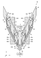
次に、本実施の形態のゲートフィンガー61~68の配置について説明する。図7に示されるように、一方の傾斜配線部60aからは、ゲートフィンガー61~64がY軸正方向に延在している。これらゲートフィンガー61~64は、Y軸正方向に対して時計回りに90°未満の角度で傾斜する斜め方向(第1の配列方向)に沿って一定間隔で配列されている。また、ゲートフィンガー61~64は、Y軸方向に互いにずれた位置にそれぞれ配置されている。他方の傾斜配線部60bからは、ゲートフィンガー65~68がY軸正方向に延在している。これらゲートフィンガー65~68は、Y軸正方向に対して反時計回りに90°未満の角度で傾斜する斜め方向(第2の配列方向)に沿って一定間隔で配列されている。また、ゲートフィンガー65~68は、Y軸方向に互いにずれた位置にそれぞれ配置されている。したがって、ゲートフィンガー61~68は、全体として、V字状に配置されている。なお、ドレイン電極41~45及びソース電極51~54は、このようなゲートフィンガー61~68の配置に合わせてほぼ平行四辺形の形状を有する。
このようにしてゲートフィンガー61~68が配置されると、一方の傾斜配線部60aから延在するゲートフィンガー61~64の相互間(特に、ソース電極またはドレイン電極を介して隣り合うゲートフィンガー間)のX軸方向から視たときの重複範囲をほぼ無くすことができる。同様に、他方の傾斜配線部60bから延在するゲートフィンガー65~68の相互間(特に、ソース電極またはドレイン電極を介して隣り合うゲートフィンガー間)のX軸方向から視たときの重複範囲もほぼ無くすことができる。これにより、ゲートフィンガー61~68で発生する熱の分布の空間的な重なりを低減させることができる。したがって、従来のマルチフィンガー構造と比べると、本実施の形態のマルチフィンガー構造は、熱抵抗の増大を抑制することができる。
以上に説明したように実施の形態3の半導体装置1Bは、従来のマルチフィンガー構造と比べると、ゲートフィンガー61~68のX軸方向における間隔を拡げずに放熱性の向上を図ることができる。したがって、半導体装置1Bの小型化が容易である。また、ドレイン電極41~45のX軸方向におけるサイズも拡大せずに済むことから、ドレイン電極11~15に起因する寄生容量を増大させずに放熱性の向上を実現することができるという利点がある。
また、本実施の形態3の半導体装置1Bも、IM-FETとして、あるいはMMICの一部として電力増幅器に使用することができる。特に、MMICの一部として半導体装置1Bが使用される場合は、図7に示されるように傾斜配線部60a,60b間の領域(V字形状の谷間の領域)に出力回路2を配置することができることから、電力増幅器全体の小型化を容易に実現することができる。
実施の形態4.
次に、本発明に係る実施の形態4について説明する。上記実施の形態1~3では、エアブリッジを使用して各ソース電極が接地用の接続導体と接続されている。これに対し、以下に説明される実施の形態4,5では、各ソース電極の裏面に接地用のビア導体(ISV:Island Source Via)が接続される。このため、実施の形態4,5では、接地用の接続導体が不要となる。
次に、本発明に係る実施の形態4について説明する。上記実施の形態1~3では、エアブリッジを使用して各ソース電極が接地用の接続導体と接続されている。これに対し、以下に説明される実施の形態4,5では、各ソース電極の裏面に接地用のビア導体(ISV:Island Source Via)が接続される。このため、実施の形態4,5では、接地用の接続導体が不要となる。
図8は、本発明に係る実施の形態4であるマルチフィンガー構造の半導体装置1Cのレイアウトを示す平面図である。図9は、図8に示した半導体装置1Cの一部を構成する単位トランジスタ構造の概略断面図である。図9には、X軸及びZ軸を含むX-Z平面に平行な断面が示されている。
図8に示されるように半導体装置1Cは、ドレイン電極71~75を含む導体パターン70と、ソース電極91,92,93,94と、これらソース電極91,92,93,94の裏面にそれぞれ設けられたビア導体91R,92R,93R,94Rと、ゲートフィンガー81~88を含む導体パターン80とを備えて構成されている。これら導体パターン70,80及びソース電極91~94は、図9に示される積層体5の上に形成される。
導体パターン80は、高周波信号を伝達する入力回路3と電気的に接続されるべき信号入力用の接続端部89と、この接続端部89から分岐してX軸正方向に延在する配線部80aと、接続端部89から分岐してX軸負方向に延在する配線部80bと、これら配線部80a,80bからY軸正方向に延在する一群のゲートフィンガー81~88とを有している。なお、本実施の形態では、ゲートフィンガー81~88の総数は8個であるが、この個数に限定されるものではない。
ゲートフィンガー81~88の各々は、Y軸正方向(予め定められた延在方向)に延在する直線状のフィンガー形状を有するゲート電極である。これらゲートフィンガー81~88は、同一寸法を有し、且つX軸方向において一定間隔(ピッチ)で配列されている。導体パターン80は、NiやAuなどの金属材料を用いて、たとえば蒸着法及びドライエッチングによって形成可能である。ここで、配線部80a,80b、ゲートフィンガー81~88及び接続端部89は、同一の成膜工程で同時に成膜されてもよいし、あるいは、互いに異なる成膜工程で個別に成膜されてもよい。少なくともゲートフィンガー81~88は、図9のバリア層7とショットキー接合するように成膜される。
一方、図8に示される導体パターン70は、高周波信号を伝達する出力回路2と電気的に接続されるべき信号出力用の接続端部79と、この接続端部79からX軸正方向に延在する配線部70aと、この接続端部79からX軸負方向に延在する配線部70bと、これら配線部70a,70bからY軸負方向に延在するドレイン電極71,72,73,74,75とを有している。また、これらドレイン電極71,72,73,74,75とそれぞれ対応する位置にソース電極91,92,93,94,95が設けられている。図8に示されるようにドレイン電極71~75及びソース電極91~95は、ソース電極とドレイン電極とがX軸方向に沿って交互に配列された電極パターンを構成するように配置されている。交互に配列されたソース電極とドレイン電極との間の各領域に8個のゲートフィンガー81~88の各々が配置されている。よって、本実施の形態では、8個の単位トランジスタ構造が形成されている。
導体パターン70及びソース電極91~94は、TiやAlなどの金属材料を用いて、たとえば蒸着法及びドライエッチングによって形成可能である。ここで、導体パターン70及びソース電極91~94は、同一の成膜工程で同時に成膜されてもよいし、あるいは、互いに異なる成膜工程で個別に成膜されてもよい。少なくともソース電極91~94及びドレイン電極71~75は、図9のバリア層7とオーミック接合するように成膜される。また、ソース電極91,92,93,94は、図9の積層体5及び下地基板4を下地基板4の厚み方向(Z軸方向)に貫通する接地用のビア導体91R,92R,93R,94Rとそれぞれ電気的に接続されている。ビア導体91R,92R,93R,94Rは、図9に示される接地用の裏面配線層90と接続されて接地されている。ビア導体91R~94Rは、たとえば、ドライエッチングにより下地基板4の裏面から積層体5の上面まで貫通するビアホールを形成し、次に、これらビアホールに導電材料を埋め込むことにより、形成可能である。
図8に示されるように、ゲートフィンガー81~88は、実施の形態1のゲートフィンガー31~38と同様に配置されている。すなわち、ゲートフィンガー81~88は、上方の位置に配置されたゲートフィンガー81,83,86,88と、下方の位置に配置されたゲートフィンガー82,84,85,87とに2分される。上方に配置されたゲートフィンガー81,83,86,88は、X軸方向において一列に配列されており、下方に配置された他のゲートフィンガー82,84,85,87もX軸方向において一列に配列されている。ここで、上方に配置されたゲートフィンガー81,83,86,88と、下方に配置されたゲートフィンガー82,84,85,87とは、Y軸方向(すなわちゲートフィンガー81~88の延在方向)において互いにずれた位置に配置されている。また、本実施の形態のゲートフィンガー81~88は、Y軸方向において上下互い違いの位置に配置されている。言い換えれば、ゲートフィンガー81~88は、ソース電極またはドレイン電極を介して隣り合うゲートフィンガーの位置がY軸方向に互いにずれるように配置されている。
ドレイン電極71~75及びソース電極91~94は、このようなゲートフィンガー81~88の配置に合わせてほぼ平行四辺形の形状を有する。また、配線部80a,80bの内側エッジは、ゲートフィンガー81~88の配置に合わせて折り曲がった波形の形状を有している。
このようにしてゲートフィンガー81~88が配置されると、上方に配置されたゲートフィンガー81,83,86,88と下方に配置されたゲートフィンガー82,84,85,87との間のX軸方向から視たときの重複範囲の長さが小さくなる。これにより、ゲートフィンガー81~88で発生する熱の分布の空間的な重なりを低減させることができる。よって、従来のマルチフィンガー構造と比べると、本実施の形態のマルチフィンガー構造は、熱抵抗の増大を抑制することができる。したがって、実施の形態1の場合と同様に、半導体装置1の小型化を容易に実現することができる。また、ドレイン電極71~75に起因する寄生容量を増大させずに放熱性の向上を実現することができる。
更に、本実施の形態では、ソース電極91~94の裏面に接地用のビア導体91R~94Rが設けられているので、上記実施の形態1~3の接続導体20A~20D,50A~50Dを使用せずにソース電極91~94を接地することができる。よって、実施の形態1~3と比べるとデバイスサイズの更なる小型化を実現することができる。また、エアブリッジを用いないためにソースインダクタンスの低減も可能である。更に、図8に示されるように、配線部70a,70b,80a,80bの面積を、上記実施の形態1~3のそれらと比べると大きくすることができるので、ソース電極間及びドレイン電極間における高周波信号の位相差を低減することができる。したがって、利得を向上させるこことができ、より高周波帯域に適した構造を実現することができる。
なお、本実施の形態4の半導体装置1Cも、IM-FETとして、あるいはMMICの一部として電力増幅器に使用することができる。
実施の形態5.
次に、上記実施の形態4の変形例である実施の形態5について説明する。図10は、本発明に係る実施の形態5である半導体装置1Dのレイアウトを示す平面図である。本実施の形態の半導体装置1Dの構成は、上記導体パターン70,80に代えて図10の導体パターン70A,80Aを有する点を除いて、実施の形態4の半導体装置1Cの構成と同じである。
次に、上記実施の形態4の変形例である実施の形態5について説明する。図10は、本発明に係る実施の形態5である半導体装置1Dのレイアウトを示す平面図である。本実施の形態の半導体装置1Dの構成は、上記導体パターン70,80に代えて図10の導体パターン70A,80Aを有する点を除いて、実施の形態4の半導体装置1Cの構成と同じである。
上記実施の形態4では、図8に示されるように導体パターン70配線部70a,70bの外側エッジ70e,70fはX軸方向に対して傾斜していない。同様に、導体パターン80の配線部80a,80bの外側エッジ80e,80fもX軸方向に対して傾斜しない。これに対し、本実施の形態の導体パターン70Aの配線部70Aa,70Abは、X軸方向に対して傾斜する傾斜形状を有している。同様に、導体パターン80Aの配線部80Aa,80Abも、X軸方向に対して傾斜する傾斜形状を有している。本実施の形態の導体パターン70A,80Aの構成は、外側エッジ70Ae,70Af,80Ae,80Afの傾斜形状を除いて、上記実施の形態4の導体パターン70,80の構成と同じである。
図10に示されるように、配線部70Aa,70Abの外側エッジ70Ae,70Afの形状は、当該配線部70Aa,70AbのX軸方向の幅が接続端部79からソース電極71~75へ向かうに従って拡大するように形成されている。同様に、配線部80Aa,80Abの外側エッジ80Ae,80Afの形状も、当該配線部80Aa,80AbのX軸方向の幅が接続端部89からソース電極71~75へ向かうに従って拡大するように形成されている。このように外側エッジ70Ae,70Af,80Ae,80Afが形成されることにより、ソース電極間及びドレイン電極間における高周波信号の位相差を更に低減することが可能となる。したがって、実施の形態4と比べると利得を更に向上させるこことができ、より高周波帯域に適した構造を実現することができる。
以上、図面を参照して本発明に係る種々の実施の形態1~5について述べたが、これら実施の形態は本発明の例示であり、これら実施の形態以外の様々な形態を採用することもできる。たとえば、上記実施の形態1~5の半導体装置1,1A~1DのHEMT構造は、いずれも、GaNを用いた高周波デバイスであるが、これに限定されるものではない。
なお、本発明の範囲内において、上記実施の形態1~5の自由な組み合わせ、各実施の形態の任意の構成要素の変形、または各実施の形態の任意の構成要素の省略が可能である。
本発明に係る半導体装置は、高周波帯域で動作する電力増幅器に使用され得るので、たとえば、レーダ装置、アンテナ装置、マイクロ波通信装置あるいは高周波測定器に適用することができるものである。
1,1A~1D 半導体装置、2 出力回路、3 入力回路、4 下地基板、5 積層体、6 チャネル層、7 バリア層、8 保護膜、10 導体パターン、11~15 ドレイン電極、19 接続端部、20A~20D 接続導体、21~24 ソース電極、25~28 エアブリッジ、29A~29D ビア導体、30 導体パターン、30a,30b 配線部、31~38 ゲートフィンガー、39 接続端部、40 導体パターン、41~45 ドレイン電極、50A~50D 接続導体、51~54 ソース電極、55~58,55B,56B,57B,58B エアブリッジ、59A~59D ビア導体、60 導体パターン、60a,60b 傾斜配線部、61~68 ゲートフィンガー、70,70A 導体パターン、70a,70b,70Aa,70Ab 配線部、70e,70f,70Ae,70Af 外側エッジ、71~75 ドレイン電極、79 接続端部、80,80A 導体パターン、80a,80b,80Aa,80Ab 配線部、80e,80f,80Ae,80Af 外側エッジ、81~88 ゲートフィンガー、90 裏面配線層、91~94 ソース電極、91R~94R ビア導体。
Claims (12)
- 互いに対向する第1及び第2の主面を有する下地基板と、
前記第1の主面上に形成されている半導体層と、
前記半導体層上で予め定められた少なくとも1つの配列方向に沿ってドレイン電極及びソース電極が交互に配列されている電極パターンと、
各々が前記半導体層上で前記少なくとも1つの配列方向とは異なる延在方向に延在する形状を有するとともに、各々が前記ドレイン電極と前記ソース電極との間の領域に配置されている一群のゲートフィンガーと
を備え、
前記一群のゲートフィンガーは、前記延在方向に互いにずれた位置にそれぞれ配置された複数のゲートフィンガーを含むことを特徴とする半導体装置。 - 請求項1記載の半導体装置であって、
前記複数のゲートフィンガーは、
前記少なくとも1つの配列方向に沿って一列に配列されている2個以上のゲートフィンガーと、
前記2個以上のゲートフィンガーに対して前記延在方向にずれた位置に配置されている少なくとも1個のゲートフィンガーと
を含むことを特徴とする半導体装置。 - 請求項2記載の半導体装置であって、前記少なくとも1個のゲートフィンガーは、2個以上のゲートフィンガーからなり、前記少なくとも1つの配列方向に沿って一列に配列されていることを特徴とする半導体装置。
- 請求項1記載の半導体装置であって、前記少なくとも1つの配列方向は、前記延在方向に対して傾斜する方向であることを特徴とする半導体装置。
- 請求項1記載の半導体装置であって、
前記少なくとも1つの配列方向は、前記延在方向に対して時計回りの方向に90°未満の角度で傾斜する第1の配列方向と、前記延在方向に対して反時計回りの方向に90°未満の角度で傾斜する第2の配列方向とからなり、
前記複数のゲートフィンガーは、前記第1の配列方向及び前記第2の配列方向に沿って配列されていることを特徴とする半導体装置。 - 請求項1記載の半導体装置であって、
前記半導体層上に形成され、前記ソース電極の前記延在方向における一端部と電気的に接続される第1の接続導体と、
前記半導体層及び前記下地基板を前記下地基板の厚み方向に貫通し、前記第1の接続導体と電気的に接続される第1の接地用ビア導体と、
前記半導体層上に形成され、前記ソース電極の前記延在方向における他端部と電気的に接続される第2の接続導体と、
前記半導体層及び前記下地基板を前記厚み方向に貫通し、前記第2の接続導体と電気的に接続される第2の接地用ビア導体と
を更に備えることを特徴とする半導体装置。 - 請求項6記載の半導体装置であって、
前記ソース電極の当該一端部を前記第1の接続導体と電気的に接続する第1のエアブリッジと、
前記ソース電極の当該他端部を前記第2の接続導体と電気的に接続する第2のエアブリッジと
を更に備えることを特徴とする半導体装置。 - 請求項1記載の半導体装置であって、
前記下地基板の当該第2の主面上に形成されている裏面配線層と、
前記下地基板及び前記半導体層を前記下地基板の厚み方向に貫通して前記ソース電極を前記裏面配線層と電気的に接続する接地用ビア導体と
を更に備えることを特徴とする半導体装置。 - 請求項8記載の半導体装置であって、
信号入力用の第1の接続端部と、
信号出力用の第2の接続端部と、
前記第1の接続端部と前記ソース電極との間を電気的に接続する第1の配線部と、
前記第2の接続端部と前記ドレイン電極との間を電気的に接続する第2の配線部と
を備え、
前記第1の配線部の外側エッジは、当該第1の配線部の前記少なくとも1つの配列方向における幅を前記第1の接続端部から前記ソース電極へ向かうに従って拡大させる傾斜形状を有し、
前記第2の配線部の外側エッジは、当該第2の配線部の前記少なくとも1つの配列方向における幅を前記第2の接続端部から前記ドレイン電極へ向かうに従って拡大させる傾斜形状を有する、
ことを特徴とする半導体装置。 - 請求項1記載の半導体装置であって、前記複数のゲートフィンガーは、前記少なくとも1つの配列方向において一定間隔で配列されていることを特徴とする半導体装置。
- 請求項1記載の半導体装置であって、前記半導体層は、各々がIII族窒化物半導体からなる複数の化合物半導体層が積層された積層体であることを特徴とする半導体装置。
- 請求項11記載の半導体装置であって、前記複数の化合物半導体層は、2次元電子ガスが形成されるチャネル層と、前記チャネル層上で当該チャネル層とヘテロ接合するバリア層とを含むことを特徴とする半導体装置。
Priority Applications (4)
| Application Number | Priority Date | Filing Date | Title |
|---|---|---|---|
| PCT/JP2016/071721 WO2018020549A1 (ja) | 2016-07-25 | 2016-07-25 | 半導体装置 |
| US16/319,158 US10797141B2 (en) | 2016-07-25 | 2016-07-25 | Semiconductor device |
| EP16910453.6A EP3474316B1 (en) | 2016-07-25 | 2016-07-25 | Semiconductor device |
| JP2016572778A JP6165368B1 (ja) | 2016-07-25 | 2016-07-25 | 半導体装置 |
Applications Claiming Priority (1)
| Application Number | Priority Date | Filing Date | Title |
|---|---|---|---|
| PCT/JP2016/071721 WO2018020549A1 (ja) | 2016-07-25 | 2016-07-25 | 半導体装置 |
Publications (1)
| Publication Number | Publication Date |
|---|---|
| WO2018020549A1 true WO2018020549A1 (ja) | 2018-02-01 |
Family
ID=59351386
Family Applications (1)
| Application Number | Title | Priority Date | Filing Date |
|---|---|---|---|
| PCT/JP2016/071721 Ceased WO2018020549A1 (ja) | 2016-07-25 | 2016-07-25 | 半導体装置 |
Country Status (4)
| Country | Link |
|---|---|
| US (1) | US10797141B2 (ja) |
| EP (1) | EP3474316B1 (ja) |
| JP (1) | JP6165368B1 (ja) |
| WO (1) | WO2018020549A1 (ja) |
Cited By (1)
| Publication number | Priority date | Publication date | Assignee | Title |
|---|---|---|---|---|
| US12154872B2 (en) | 2021-03-15 | 2024-11-26 | Sumitomo Electric Industries, Ltd. | Semiconductor device and power amplifier |
Families Citing this family (7)
| Publication number | Priority date | Publication date | Assignee | Title |
|---|---|---|---|---|
| JP7685129B2 (ja) * | 2020-04-03 | 2025-05-29 | マコム テクノロジー ソリューションズ ホールディングス, インコーポレイテッド | ソース、ゲート及び/又はドレイン導電性ビアを有するiii族窒化物ベースの高周波トランジスタ増幅器 |
| US11929408B2 (en) | 2020-05-14 | 2024-03-12 | Macom Technology Solutions Holdings, Inc. | Layout techniques and optimization for power transistors |
| US12310082B1 (en) * | 2021-10-20 | 2025-05-20 | National Technology & Engineering Solutions Of Sandia, Llc | Transistor with curvilinear gate configuration for improved thermal distribution |
| CN114141868B (zh) * | 2022-02-07 | 2022-04-12 | 深圳市时代速信科技有限公司 | 一种半导体器件及其制备方法 |
| CN114188407B (zh) * | 2022-02-17 | 2022-05-06 | 深圳市时代速信科技有限公司 | 一种半导体器件电极结构、制作方法及半导体器件 |
| US12610605B2 (en) * | 2022-11-28 | 2026-04-21 | Globalfoundries U.S. Inc. | IC structure with gate electrode fully within V-shaped cavity |
| US12599008B2 (en) * | 2023-04-06 | 2026-04-07 | Nxp Usa, Inc. | Transistor with source manifold in non-active die region |
Citations (3)
| Publication number | Priority date | Publication date | Assignee | Title |
|---|---|---|---|---|
| JP2002270822A (ja) * | 2001-03-09 | 2002-09-20 | Toshiba Corp | 半導体装置 |
| JP2004349467A (ja) * | 2003-05-22 | 2004-12-09 | Mitsubishi Electric Corp | 電界効果トランジスタとモノリシックマイクロ波集積回路 |
| WO2008053748A1 (fr) * | 2006-11-02 | 2008-05-08 | Kabushiki Kaisha Toshiba | Dispositif semiconducteur |
Family Cites Families (10)
| Publication number | Priority date | Publication date | Assignee | Title |
|---|---|---|---|---|
| JPS62224085A (ja) * | 1986-03-26 | 1987-10-02 | Toshiba Corp | 電界効果型半導体装置 |
| DE69007351T2 (de) * | 1989-06-30 | 1994-09-08 | Texas Instruments Inc | Thermisch optimierter parallelgeschalteter Transistor. |
| JP3499103B2 (ja) * | 1997-02-21 | 2004-02-23 | 三菱電機株式会社 | 半導体装置 |
| JP4965982B2 (ja) * | 2006-12-04 | 2012-07-04 | 株式会社東芝 | 電界効果トランジスタ |
| JP5106041B2 (ja) * | 2007-10-26 | 2012-12-26 | 株式会社東芝 | 半導体装置 |
| EP2161754A3 (en) | 2008-09-03 | 2010-06-16 | Kabushiki Kaisha Toshiba | A semiconductor device and fabrication method for the same |
| JP4908475B2 (ja) | 2008-09-03 | 2012-04-04 | 株式会社東芝 | 半導体装置 |
| JP4843651B2 (ja) | 2008-09-03 | 2011-12-21 | 株式会社東芝 | 半導体装置 |
| US8183892B2 (en) * | 2009-06-05 | 2012-05-22 | Fairchild Semiconductor Corporation | Monolithic low impedance dual gate current sense MOSFET |
| JP5983117B2 (ja) * | 2012-07-11 | 2016-08-31 | 三菱電機株式会社 | 半導体装置 |
-
2016
- 2016-07-25 WO PCT/JP2016/071721 patent/WO2018020549A1/ja not_active Ceased
- 2016-07-25 EP EP16910453.6A patent/EP3474316B1/en active Active
- 2016-07-25 US US16/319,158 patent/US10797141B2/en active Active
- 2016-07-25 JP JP2016572778A patent/JP6165368B1/ja active Active
Patent Citations (3)
| Publication number | Priority date | Publication date | Assignee | Title |
|---|---|---|---|---|
| JP2002270822A (ja) * | 2001-03-09 | 2002-09-20 | Toshiba Corp | 半導体装置 |
| JP2004349467A (ja) * | 2003-05-22 | 2004-12-09 | Mitsubishi Electric Corp | 電界効果トランジスタとモノリシックマイクロ波集積回路 |
| WO2008053748A1 (fr) * | 2006-11-02 | 2008-05-08 | Kabushiki Kaisha Toshiba | Dispositif semiconducteur |
Cited By (1)
| Publication number | Priority date | Publication date | Assignee | Title |
|---|---|---|---|---|
| US12154872B2 (en) | 2021-03-15 | 2024-11-26 | Sumitomo Electric Industries, Ltd. | Semiconductor device and power amplifier |
Also Published As
| Publication number | Publication date |
|---|---|
| US20200235215A1 (en) | 2020-07-23 |
| JP6165368B1 (ja) | 2017-07-19 |
| EP3474316A1 (en) | 2019-04-24 |
| EP3474316B1 (en) | 2021-03-03 |
| EP3474316A4 (en) | 2019-07-24 |
| US10797141B2 (en) | 2020-10-06 |
| JPWO2018020549A1 (ja) | 2018-07-26 |
Similar Documents
| Publication | Publication Date | Title |
|---|---|---|
| JP6165368B1 (ja) | 半導体装置 | |
| JP6743170B2 (ja) | バイパスされたゲート構造を有するトランジスタ | |
| CN1757119B (zh) | 以第三族氮化物为基的倒装片集成电路及其制造方法 | |
| JP5712516B2 (ja) | 半導体装置 | |
| TWI484630B (zh) | 具有閘極源場極板之寬能帶隙電晶體 | |
| TWI355741B (ja) | ||
| CN107799590B (zh) | 一种大栅宽的GaN基微波功率器件及其制造方法 | |
| US20130228789A1 (en) | Semiconductor device | |
| WO2008069074A1 (ja) | 半導体装置及び半導体装置の製造方法 | |
| JP2012191224A (ja) | トランジスタデバイスおよび高電子移動度トランジスタ(hemt) | |
| CN111354640B (zh) | 一种半导体器件及其制备方法 | |
| Akso et al. | First demonstration of four-finger N-polar GaN HEMT exhibiting record 712-mW output power with 31.7% PAE at 94 GHz | |
| JP2013098274A (ja) | 半導体装置 | |
| US20180047822A1 (en) | Semiconductor device | |
| KR102792556B1 (ko) | 고전자 이동도 트랜지스터 | |
| CN110970498A (zh) | 一种半导体器件及其制备方法 | |
| JP2010165789A (ja) | 半導体集積回路およびその製造方法 | |
| US20190006464A1 (en) | Fet with micro-scale device array | |
| US8816397B2 (en) | Ring-shaped transistors providing reduced self-heating | |
| JP7456517B2 (ja) | トランジスタ | |
| US9472497B2 (en) | Semiconductor device | |
| KR20230055221A (ko) | GaN RF HEMT 소자 및 그 제조방법 | |
| US20240162340A1 (en) | Semiconductor device and manufacturing method | |
| WO2017098603A1 (ja) | 窒化物半導体装置 | |
| JP5443769B2 (ja) | 半導体装置 |
Legal Events
| Date | Code | Title | Description |
|---|---|---|---|
| ENP | Entry into the national phase |
Ref document number: 2016572778 Country of ref document: JP Kind code of ref document: A |
|
| 121 | Ep: the epo has been informed by wipo that ep was designated in this application |
Ref document number: 16910453 Country of ref document: EP Kind code of ref document: A1 |
|
| ENP | Entry into the national phase |
Ref document number: 2016910453 Country of ref document: EP Effective date: 20190118 |
|
| NENP | Non-entry into the national phase |
Ref country code: DE |