WO2018021101A1 - 電力管理装置、電力管理方法及び電力管理システム - Google Patents
電力管理装置、電力管理方法及び電力管理システム Download PDFInfo
- Publication number
- WO2018021101A1 WO2018021101A1 PCT/JP2017/026035 JP2017026035W WO2018021101A1 WO 2018021101 A1 WO2018021101 A1 WO 2018021101A1 JP 2017026035 W JP2017026035 W JP 2017026035W WO 2018021101 A1 WO2018021101 A1 WO 2018021101A1
- Authority
- WO
- WIPO (PCT)
- Prior art keywords
- power
- control
- tidal flow
- reverse
- power management
- Prior art date
- Legal status (The legal status is an assumption and is not a legal conclusion. Google has not performed a legal analysis and makes no representation as to the accuracy of the status listed.)
- Ceased
Links
Images
Classifications
-
- H—ELECTRICITY
- H02—GENERATION; CONVERSION OR DISTRIBUTION OF ELECTRIC POWER
- H02J—ELECTRIC POWER NETWORKS; CIRCUIT ARRANGEMENTS OR SYSTEMS FOR SUPPLYING OR DISTRIBUTING ELECTRIC POWER; SYSTEMS FOR STORING ELECTRIC ENERGY
- H02J3/00—Circuit arrangements for AC mains or AC distribution networks
- H02J3/12—Arrangements for adjusting voltage in AC networks by changing a characteristic of the network load
- H02J3/14—Arrangements for adjusting voltage in AC networks by changing a characteristic of the network load by switching loads on to, or off from, the networks, e.g. progressively balanced loading
-
- H—ELECTRICITY
- H02—GENERATION; CONVERSION OR DISTRIBUTION OF ELECTRIC POWER
- H02J—ELECTRIC POWER NETWORKS; CIRCUIT ARRANGEMENTS OR SYSTEMS FOR SUPPLYING OR DISTRIBUTING ELECTRIC POWER; SYSTEMS FOR STORING ELECTRIC ENERGY
- H02J13/00—Circuit arrangements for providing remote monitoring or remote control of equipment in a power distribution network
-
- H—ELECTRICITY
- H02—GENERATION; CONVERSION OR DISTRIBUTION OF ELECTRIC POWER
- H02J—ELECTRIC POWER NETWORKS; CIRCUIT ARRANGEMENTS OR SYSTEMS FOR SUPPLYING OR DISTRIBUTING ELECTRIC POWER; SYSTEMS FOR STORING ELECTRIC ENERGY
- H02J13/00—Circuit arrangements for providing remote monitoring or remote control of equipment in a power distribution network
- H02J13/13—Circuit arrangements for providing remote monitoring or remote control of equipment in a power distribution network characterised by the transmission of data to equipment in the power network
- H02J13/1331—Circuit arrangements for providing remote monitoring or remote control of equipment in a power distribution network characterised by the transmission of data to equipment in the power network using wireless data transmission
-
- H—ELECTRICITY
- H02—GENERATION; CONVERSION OR DISTRIBUTION OF ELECTRIC POWER
- H02J—ELECTRIC POWER NETWORKS; CIRCUIT ARRANGEMENTS OR SYSTEMS FOR SUPPLYING OR DISTRIBUTING ELECTRIC POWER; SYSTEMS FOR STORING ELECTRIC ENERGY
- H02J13/00—Circuit arrangements for providing remote monitoring or remote control of equipment in a power distribution network
- H02J13/14—Circuit arrangements for providing remote monitoring or remote control of equipment in a power distribution network the power network being locally controlled, e.g. home energy management systems [HEMS]
-
- H—ELECTRICITY
- H02—GENERATION; CONVERSION OR DISTRIBUTION OF ELECTRIC POWER
- H02J—ELECTRIC POWER NETWORKS; CIRCUIT ARRANGEMENTS OR SYSTEMS FOR SUPPLYING OR DISTRIBUTING ELECTRIC POWER; SYSTEMS FOR STORING ELECTRIC ENERGY
- H02J3/00—Circuit arrangements for AC mains or AC distribution networks
-
- H—ELECTRICITY
- H02—GENERATION; CONVERSION OR DISTRIBUTION OF ELECTRIC POWER
- H02J—ELECTRIC POWER NETWORKS; CIRCUIT ARRANGEMENTS OR SYSTEMS FOR SUPPLYING OR DISTRIBUTING ELECTRIC POWER; SYSTEMS FOR STORING ELECTRIC ENERGY
- H02J3/00—Circuit arrangements for AC mains or AC distribution networks
- H02J3/28—Arrangements for balancing of the load in networks by storage of energy
- H02J3/32—Arrangements for balancing of the load in networks by storage of energy using batteries or super capacitors with converting means
-
- H—ELECTRICITY
- H02—GENERATION; CONVERSION OR DISTRIBUTION OF ELECTRIC POWER
- H02J—ELECTRIC POWER NETWORKS; CIRCUIT ARRANGEMENTS OR SYSTEMS FOR SUPPLYING OR DISTRIBUTING ELECTRIC POWER; SYSTEMS FOR STORING ELECTRIC ENERGY
- H02J3/00—Circuit arrangements for AC mains or AC distribution networks
- H02J3/38—Arrangements for feeding a single network from two or more generators or sources in parallel; Arrangements for feeding already energised networks from additional generators or sources in parallel
-
- H—ELECTRICITY
- H02—GENERATION; CONVERSION OR DISTRIBUTION OF ELECTRIC POWER
- H02J—ELECTRIC POWER NETWORKS; CIRCUIT ARRANGEMENTS OR SYSTEMS FOR SUPPLYING OR DISTRIBUTING ELECTRIC POWER; SYSTEMS FOR STORING ELECTRIC ENERGY
- H02J7/00—Circuit arrangements for charging or discharging batteries or for supplying loads from batteries
- H02J7/34—Parallel operation in networks using both storage and other DC sources, e.g. providing buffering
- H02J7/35—Parallel operation in networks using both storage and other DC sources, e.g. providing buffering with light sensitive cells
-
- H—ELECTRICITY
- H02—GENERATION; CONVERSION OR DISTRIBUTION OF ELECTRIC POWER
- H02J—ELECTRIC POWER NETWORKS; CIRCUIT ARRANGEMENTS OR SYSTEMS FOR SUPPLYING OR DISTRIBUTING ELECTRIC POWER; SYSTEMS FOR STORING ELECTRIC ENERGY
- H02J2105/00—Networks for supplying or distributing electric power characterised by their spatial reach or by the load
- H02J2105/10—Local stationary networks having a local or delimited stationary reach
- H02J2105/12—Local stationary networks having a local or delimited stationary reach supplying households or buildings
-
- H—ELECTRICITY
- H02—GENERATION; CONVERSION OR DISTRIBUTION OF ELECTRIC POWER
- H02J—ELECTRIC POWER NETWORKS; CIRCUIT ARRANGEMENTS OR SYSTEMS FOR SUPPLYING OR DISTRIBUTING ELECTRIC POWER; SYSTEMS FOR STORING ELECTRIC ENERGY
- H02J2105/00—Networks for supplying or distributing electric power characterised by their spatial reach or by the load
- H02J2105/40—Networks for supplying or distributing electric power characterised by their spatial reach or by the load characterised by the loads connecting to the networks or being supplied by the networks
- H02J2105/42—Home appliances
-
- Y—GENERAL TAGGING OF NEW TECHNOLOGICAL DEVELOPMENTS; GENERAL TAGGING OF CROSS-SECTIONAL TECHNOLOGIES SPANNING OVER SEVERAL SECTIONS OF THE IPC; TECHNICAL SUBJECTS COVERED BY FORMER USPC CROSS-REFERENCE ART COLLECTIONS [XRACs] AND DIGESTS
- Y02—TECHNOLOGIES OR APPLICATIONS FOR MITIGATION OR ADAPTATION AGAINST CLIMATE CHANGE
- Y02B—CLIMATE CHANGE MITIGATION TECHNOLOGIES RELATED TO BUILDINGS, e.g. HOUSING, HOUSE APPLIANCES OR RELATED END-USER APPLICATIONS
- Y02B70/00—Technologies for an efficient end-user side electric power management and consumption
- Y02B70/30—Systems integrating technologies related to power network operation and communication or information technologies for improving the carbon footprint of the management of residential or tertiary loads, i.e. smart grids as climate change mitigation technology in the buildings sector, including also the last stages of power distribution and the control, monitoring or operating management systems at local level
- Y02B70/3225—Demand response systems, e.g. load shedding, peak shaving
-
- Y—GENERAL TAGGING OF NEW TECHNOLOGICAL DEVELOPMENTS; GENERAL TAGGING OF CROSS-SECTIONAL TECHNOLOGIES SPANNING OVER SEVERAL SECTIONS OF THE IPC; TECHNICAL SUBJECTS COVERED BY FORMER USPC CROSS-REFERENCE ART COLLECTIONS [XRACs] AND DIGESTS
- Y02—TECHNOLOGIES OR APPLICATIONS FOR MITIGATION OR ADAPTATION AGAINST CLIMATE CHANGE
- Y02B—CLIMATE CHANGE MITIGATION TECHNOLOGIES RELATED TO BUILDINGS, e.g. HOUSING, HOUSE APPLIANCES OR RELATED END-USER APPLICATIONS
- Y02B90/00—Enabling technologies or technologies with a potential or indirect contribution to GHG emissions mitigation
- Y02B90/20—Smart grids as enabling technology in buildings sector
-
- Y—GENERAL TAGGING OF NEW TECHNOLOGICAL DEVELOPMENTS; GENERAL TAGGING OF CROSS-SECTIONAL TECHNOLOGIES SPANNING OVER SEVERAL SECTIONS OF THE IPC; TECHNICAL SUBJECTS COVERED BY FORMER USPC CROSS-REFERENCE ART COLLECTIONS [XRACs] AND DIGESTS
- Y02—TECHNOLOGIES OR APPLICATIONS FOR MITIGATION OR ADAPTATION AGAINST CLIMATE CHANGE
- Y02E—REDUCTION OF GREENHOUSE GAS [GHG] EMISSIONS, RELATED TO ENERGY GENERATION, TRANSMISSION OR DISTRIBUTION
- Y02E40/00—Technologies for an efficient electrical power generation, transmission or distribution
- Y02E40/70—Smart grids as climate change mitigation technology in the energy generation sector
-
- Y—GENERAL TAGGING OF NEW TECHNOLOGICAL DEVELOPMENTS; GENERAL TAGGING OF CROSS-SECTIONAL TECHNOLOGIES SPANNING OVER SEVERAL SECTIONS OF THE IPC; TECHNICAL SUBJECTS COVERED BY FORMER USPC CROSS-REFERENCE ART COLLECTIONS [XRACs] AND DIGESTS
- Y02—TECHNOLOGIES OR APPLICATIONS FOR MITIGATION OR ADAPTATION AGAINST CLIMATE CHANGE
- Y02E—REDUCTION OF GREENHOUSE GAS [GHG] EMISSIONS, RELATED TO ENERGY GENERATION, TRANSMISSION OR DISTRIBUTION
- Y02E60/00—Enabling technologies; Technologies with a potential or indirect contribution to GHG emissions mitigation
-
- Y—GENERAL TAGGING OF NEW TECHNOLOGICAL DEVELOPMENTS; GENERAL TAGGING OF CROSS-SECTIONAL TECHNOLOGIES SPANNING OVER SEVERAL SECTIONS OF THE IPC; TECHNICAL SUBJECTS COVERED BY FORMER USPC CROSS-REFERENCE ART COLLECTIONS [XRACs] AND DIGESTS
- Y02—TECHNOLOGIES OR APPLICATIONS FOR MITIGATION OR ADAPTATION AGAINST CLIMATE CHANGE
- Y02E—REDUCTION OF GREENHOUSE GAS [GHG] EMISSIONS, RELATED TO ENERGY GENERATION, TRANSMISSION OR DISTRIBUTION
- Y02E70/00—Other energy conversion or management systems reducing GHG emissions
- Y02E70/30—Systems combining energy storage with energy generation of non-fossil origin
-
- Y—GENERAL TAGGING OF NEW TECHNOLOGICAL DEVELOPMENTS; GENERAL TAGGING OF CROSS-SECTIONAL TECHNOLOGIES SPANNING OVER SEVERAL SECTIONS OF THE IPC; TECHNICAL SUBJECTS COVERED BY FORMER USPC CROSS-REFERENCE ART COLLECTIONS [XRACs] AND DIGESTS
- Y04—INFORMATION OR COMMUNICATION TECHNOLOGIES HAVING AN IMPACT ON OTHER TECHNOLOGY AREAS
- Y04S—SYSTEMS INTEGRATING TECHNOLOGIES RELATED TO POWER NETWORK OPERATION, COMMUNICATION OR INFORMATION TECHNOLOGIES FOR IMPROVING THE ELECTRICAL POWER GENERATION, TRANSMISSION, DISTRIBUTION, MANAGEMENT OR USAGE, i.e. SMART GRIDS
- Y04S10/00—Systems supporting electrical power generation, transmission or distribution
- Y04S10/12—Monitoring or controlling equipment for energy generation units, e.g. distributed energy generation [DER] or load-side generation
- Y04S10/123—Monitoring or controlling equipment for energy generation units, e.g. distributed energy generation [DER] or load-side generation the energy generation units being or involving renewable energy sources
-
- Y—GENERAL TAGGING OF NEW TECHNOLOGICAL DEVELOPMENTS; GENERAL TAGGING OF CROSS-SECTIONAL TECHNOLOGIES SPANNING OVER SEVERAL SECTIONS OF THE IPC; TECHNICAL SUBJECTS COVERED BY FORMER USPC CROSS-REFERENCE ART COLLECTIONS [XRACs] AND DIGESTS
- Y04—INFORMATION OR COMMUNICATION TECHNOLOGIES HAVING AN IMPACT ON OTHER TECHNOLOGY AREAS
- Y04S—SYSTEMS INTEGRATING TECHNOLOGIES RELATED TO POWER NETWORK OPERATION, COMMUNICATION OR INFORMATION TECHNOLOGIES FOR IMPROVING THE ELECTRICAL POWER GENERATION, TRANSMISSION, DISTRIBUTION, MANAGEMENT OR USAGE, i.e. SMART GRIDS
- Y04S20/00—Management or operation of end-user stationary applications or the last stages of power distribution; Controlling, monitoring or operating thereof
- Y04S20/12—Energy storage units, uninterruptible power supply [UPS] systems or standby or emergency generators, e.g. in the last power distribution stages
-
- Y—GENERAL TAGGING OF NEW TECHNOLOGICAL DEVELOPMENTS; GENERAL TAGGING OF CROSS-SECTIONAL TECHNOLOGIES SPANNING OVER SEVERAL SECTIONS OF THE IPC; TECHNICAL SUBJECTS COVERED BY FORMER USPC CROSS-REFERENCE ART COLLECTIONS [XRACs] AND DIGESTS
- Y04—INFORMATION OR COMMUNICATION TECHNOLOGIES HAVING AN IMPACT ON OTHER TECHNOLOGY AREAS
- Y04S—SYSTEMS INTEGRATING TECHNOLOGIES RELATED TO POWER NETWORK OPERATION, COMMUNICATION OR INFORMATION TECHNOLOGIES FOR IMPROVING THE ELECTRICAL POWER GENERATION, TRANSMISSION, DISTRIBUTION, MANAGEMENT OR USAGE, i.e. SMART GRIDS
- Y04S20/00—Management or operation of end-user stationary applications or the last stages of power distribution; Controlling, monitoring or operating thereof
- Y04S20/20—End-user application control systems
- Y04S20/222—Demand response systems, e.g. load shedding, peak shaving
-
- Y—GENERAL TAGGING OF NEW TECHNOLOGICAL DEVELOPMENTS; GENERAL TAGGING OF CROSS-SECTIONAL TECHNOLOGIES SPANNING OVER SEVERAL SECTIONS OF THE IPC; TECHNICAL SUBJECTS COVERED BY FORMER USPC CROSS-REFERENCE ART COLLECTIONS [XRACs] AND DIGESTS
- Y04—INFORMATION OR COMMUNICATION TECHNOLOGIES HAVING AN IMPACT ON OTHER TECHNOLOGY AREAS
- Y04S—SYSTEMS INTEGRATING TECHNOLOGIES RELATED TO POWER NETWORK OPERATION, COMMUNICATION OR INFORMATION TECHNOLOGIES FOR IMPROVING THE ELECTRICAL POWER GENERATION, TRANSMISSION, DISTRIBUTION, MANAGEMENT OR USAGE, i.e. SMART GRIDS
- Y04S40/00—Systems for electrical power generation, transmission, distribution or end-user application management characterised by the use of communication or information technologies, or communication or information technology specific aspects supporting them
- Y04S40/12—Systems for electrical power generation, transmission, distribution or end-user application management characterised by the use of communication or information technologies, or communication or information technology specific aspects supporting them characterised by data transport means between the monitoring, controlling or managing units and monitored, controlled or operated electrical equipment
- Y04S40/126—Systems for electrical power generation, transmission, distribution or end-user application management characterised by the use of communication or information technologies, or communication or information technology specific aspects supporting them characterised by data transport means between the monitoring, controlling or managing units and monitored, controlled or operated electrical equipment using wireless data transmission
Definitions
- the present invention relates to a power management apparatus, a power management method, and a power management system.
- power control messages such as a message requesting control of the tidal flow from the power system to the facility and a message requesting control of the reverse power flow from the facility to the power system are known.
- a power control message is transmitted based on the power supply / demand balance of the power system (for example, Patent Documents 1 and 2).
- a power management apparatus includes a receiving unit that receives a power control message from an external server, and a tidal flow from a power system to a facility or a reverse from the facility to the power system based on the power control message.
- a control unit that controls at least one of the tidal flow rate, and a transmission unit that transmits a control result of at least one of the tidal flow rate or the reverse tidal flow rate to the external server.
- the control result identifies control amount information indicating a control amount of at least one of the tidal flow or the reverse tidal flow, and a contributing device that contributes to control of at least one of the tidal flow or the reverse tidal flow. Identification information.
- the power management method includes a step A for receiving a power control message from an external server, and a tidal flow from the power system to the facility or a reverse from the facility to the power system based on the power control message.
- a step B for controlling at least one of the tidal flow rates
- a step C for transmitting a control result of at least one of the tidal flow rates or the reverse tidal flow rates to the external server.
- the control result identifies control amount information indicating a control amount of at least one of the tidal flow or the reverse tidal flow, and a contributing device that contributes to control of at least one of the tidal flow or the reverse tidal flow. Identification information.
- a power management system includes: a receiving unit that receives a power control message from an external server; and a tidal flow from a power system to a facility or a reverse from the facility to the power system based on the power control message.
- a control unit that controls at least one of the tidal flow rate, and a transmission unit that transmits a control result of at least one of the tidal flow rate or the reverse tidal flow rate to the external server.
- the control result identifies control amount information indicating a control amount of at least one of the tidal flow or the reverse tidal flow, and a contributing device that contributes to control of at least one of the tidal flow or the reverse tidal flow. Identification information.
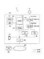
- FIG. 1 is a diagram illustrating a power management system 1 according to the embodiment.
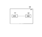
- FIG. 2 is a diagram illustrating the EMS 160 according to the embodiment.
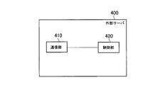
- FIG. 3 is a diagram illustrating the external server 400 according to the embodiment.
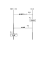
- FIG. 4 is a diagram illustrating a power management method according to the embodiment.
- drawings are schematic and the ratio of each dimension may be different from the actual one. Therefore, specific dimensions and the like should be determined in consideration of the following description. In some cases, the drawings may include portions having different dimensional relationships and ratios.
- the management system 1 includes a customer facility 100 (hereinafter referred to as a facility 100) and an external server 400.
- the facility 100 has a router 200.
- the router 200 is connected to the external server 400 via the network 300.
- the router 200 forms a local area network and is connected to each device (for example, the communication device 132 of the PCS 130, the load 150, the EMS 160, the display device 170, and the like).
- a solid line indicates a power line
- a dotted line indicates a signal line. Note that the present invention is not limited to this, and a signal may be transmitted through a power line.
- the facility 100 includes a solar battery 110, a storage battery 120, a PCS 130, a distribution board 140, a load 150, an EMS 160, and a display device 170.
- the solar cell 110 is a photoelectric conversion device that generates power in response to light reception.
- the solar cell 110 outputs the generated DC power.
- the amount of power generated by the solar cell 110 changes according to the amount of solar radiation irradiated on the solar cell 110.
- the solar cell 110 is an example of a distributed power source capable of a reverse power flow from the facility 100 to the power system 10.
- Storage battery 120 is a device that stores electric power.
- the storage battery 120 outputs the accumulated DC power.
- the storage battery 120 may be a distributed power source capable of reverse power flow from the facility 100 to the power system 10, or may be a distributed power source that does not allow reverse power flow from the facility 100 to the power system 10.
- the PCS 130 is an example of a power conversion system (PCS; Power Conditioning System) that converts at least one of output power from the distributed power source and input power to the distributed power source into AC power or DC power.
- PCS Power Conditioning System
- the PCS 130 includes a conversion device 131 and a communication device 132.
- the conversion device 131 converts DC power from the solar battery 110 into AC power, and converts DC power from the storage battery 120 into AC power. Furthermore, the converter 131 converts AC power from the power system 10 into DC power.
- the converter 131 is connected to the main power line 10L (here, the main power line 10LA and the main power line 10LB) connected to the power system 10 via the first distribution board 140A, and both the solar battery 110 and the storage battery 120 are connected. Connected to.
- the main power line 10LA is a power line that connects the power system 10 and the first distribution board 140A
- the main power line 10LB is a power line that connects the first distribution board 140A and the second distribution board 140B.
- the conversion device 131 is described as a hybrid power conversion device connected to the solar cell 110 and the storage battery 120, but the power conversion device is connected to each of the solar cell 110 and the storage battery 120. It may be configured. When it is the structure by which a power converter device is connected to each of the solar cell 110 and the storage battery 120, each power converter device can perform control similar to the hybrid type power converter device of this embodiment.
- the communication device 132 is connected to the conversion device 131, receives various messages to the conversion device 131, and transmits various messages from the conversion device 131.
- a protocol for example, a unique protocol
- PCS 130 In communication between the communication device 132 and the conversion device 131, a protocol (for example, a unique protocol) applied to the PCS 130 is used.
- the communication device 132 is connected to the router 200 by wire or wireless.
- the communication device 132 may be connected to the external server 400 via the router 200 and may receive a power suppression message from the external server 400.
- the power suppression message includes a power flow suppression message (DR; Demand Response) requesting suppression of power flow from the power system 10 to the facility 100 and a reverse power flow suppression message requesting suppression of reverse power flow from the facility 100 to the power system 10. Including at least one of the following.
- the communication device 132 may be connected to the EMS 160 via the router 200 and may communicate with a predetermined command having a predetermined format with the EMS 160.
- the predetermined format is not particularly limited, and for example, the ECHONET system, the ECHONET Lite system, the SEP2.0 system, the KNX system, or the like can be used.
- the load 150 is a device that consumes power supplied through the power line.
- the load 150 includes devices such as an air conditioner, a lighting device, a refrigerator, and a television.
- the load 150 may be a single device or may include a plurality of devices.
- the EMS 160 is a power management apparatus (EMS; Energy Management System) that manages power information indicating power in the facility 100.
- the power in the facility 100 refers to power flowing through the facility 100, power purchased by the facility 100, power sold from the facility 100, and the like. Therefore, for example, the EMS 160 manages at least the PCS 130.
- the EMS 160 may control the power generation amount of the solar battery 110, the charge amount of the storage battery 120, and the discharge amount of the storage battery 120.
- the EMS 160 may be configured integrally with the distribution board 140.
- the EMS 160 is a device connected to the network 300, and the function of the EMS 160 may be provided by a cloud service via the network 300.
- the EMS 160 is connected to the external server 400 via the router 200 and communicates with the external server 400.
- the EMS 160 is connected to each device (for example, the communication device 132 and the load 150 of the PCS 130) via the router 200, and may communicate with each device.
- the EMS 160 is connected to the display device 170 via the router 200 and may communicate with the display device 170.
- the display device 170 displays the state of the PCS 130.
- the display device 170 may display power information indicating the power in the facility 100.
- the display device 170 is, for example, a smartphone, a tablet, a television, a personal computer, or a dedicated terminal.
- the display device 170 is connected to the EMS 160 by wire or wireless and communicates with the EMS 160.
- the display device 170 may perform communication of a predetermined command having a predetermined format with the EMS 160.
- the display device 170 receives data necessary for displaying various information from the EMS 160.
- the network 300 is a communication network that connects the EMS 160 and the external server 400.
- the network 300 may be a public communication line such as the Internet.
- the network 300 may include a mobile communication network.
- the network 300 may be a dedicated communication line or a general communication line.
- the external server 400 is a server managed by a business operator such as a power generation business, a power transmission / distribution business, or a retail business.
- the external server 400 transmits a power suppression message including at least one of a power flow suppression message and a reverse power flow suppression message to the facility 100 (PCS 130 or EMS 160).
- the reverse power flow suppression message may be considered as an output suppression message instructing output suppression of the distributed power supply.
- the EMS 160 includes a communication unit 161 and a control unit 162.
- the communication unit 161 is composed of a communication module and communicates with the external server 400.
- the communication unit 161 receives a power suppression message from the external server 400.
- the communication unit 161 transmits the suppression result of at least one of the tide flow rate and the reverse tide flow rate to the external server 400.
- the suppression result includes suppression amount information indicating at least one suppression amount of tide flow or reverse tide flow, and identification information for identifying a contributing device that contributes to suppression of at least one of tide flow or reverse tide flow. Including.
- the suppression result may be a result in the middle of suppression or a result after the suppression period ends.
- the suppression amount information may be information indicating the suppression amount for each contributing device.
- the contribution device may be the load 150 that reduces the power consumption or the storage battery 120 that increases the discharge power for suppressing the tidal flow rate.
- the contributing device may be the load 150 that increases the power consumption or the storage battery 120 that increases the stored power for the suppression of the reverse power flow.
- the suppression result may include state information indicating the state of the contributing device affected by the suppression of at least one of the tidal flow rate and the reverse tidal flow rate.
- the state information includes information indicating any one of the number of times the storage battery 120 is charged, the number of discharges of the storage battery 120, and the life of the storage battery 120.
- the number of times of charging and the number of times of discharging may be the cumulative number of times since the storage battery 120 has been installed, or may be the cumulative number of times during the suppression period of the tidal flow or the reverse tidal flow.
- the suppression result may include energy information for identifying energy used by the contributing device in at least one of the tidal flow and the reverse tidal flow.
- the energy information may include information indicating the type of energy and the amount of energy.
- the type of energy is natural energy
- the amount of energy is the amount of solar radiation.
- the amount of energy may be regarded as zero, and may be represented by the selling price of the output power of the solar cell 110.
- the type of energy is gas
- the amount of energy is the amount of gas purchased.
- the amount of energy may be represented by the gas purchase price.
- the energy information may include source information that specifies energy of a source that supplies power stored in the storage battery 120.
- the source include an electric power system 10, a solar cell 110, and a fuel cell.
- the source information includes the power system 10, the solar cell 110, the fuel cell, and the like.
- the amount of energy may be the amount of energy per source.
- the content of energy information is similar to the case of suppression of tidal flow.
- the amount of energy may be information that can identify the lost profit that was not obtained by the control of the reverse power flow.
- the suppression result is used to determine an incentive given to suppression of at least one of the tidal flow and the reverse tidal flow. That is, the suppression result is used as information for specifying the cost borne by the facility 100 due to the suppression of the tidal flow or the reverse tidal flow. For example, the greater the cost incurred by the facility 100, the greater the incentive.
- the control unit 162 includes a memory and a CPU, and controls the EMS 160. For example, the control unit 162 suppresses at least one of the tidal flow rate and the reverse tidal flow rate based on the power suppression message. The control unit 162 may suppress at least one of the tidal flow rate and the reverse tidal flow rate under the control of the PCS 130.
- control unit 162 may select a contributing device that contributes to suppression of at least one of the tidal flow and the reverse tidal flow based on the energy information.
- the control unit 162 may select the contributing device based on the incentive itself.
- the external server 400 includes a communication unit 410 and a control unit 420.
- the communication unit 410 includes a communication module, and communicates with the EMS 160.
- the communication unit 410 may communicate with the communication device 132.
- the communication unit 410 transmits a power suppression message to the EMS 160.
- the communication unit 410 may transmit a power suppression message to the PCS 130.
- the communication unit 410 receives the suppression result from the EMS 160.
- the control unit 420 includes a memory and a CPU, and controls the external server 400. For example, the control unit 420 creates a supply / demand adjustment plan based on the power supply / demand balance of the power system 10, and instructs the communication unit 410 to transmit a power suppression message based on the supply / demand adjustment plan.
- control unit 420 determines an incentive to be given to the facility 100 based on the suppression result. For example, the control unit 420 identifies the cost borne by the facility 100 due to the suppression of the tide flow rate or the reverse tide flow rate based on the suppression result, and determines the incentive according to the cost. The control unit 420 gives a larger incentive as the cost of the facility 100 is increased.
- step S ⁇ b> 10 the external server 400 transmits a power suppression message to the EMS 160.
- step S11 the EMS 160 suppresses the tide flow rate or the reverse tide flow rate based on the power suppression message.
- step S12 the EMS 160 transmits the suppression result of the tide flow rate or the reverse tide flow rate to the external server 400.
- the contents of the suppression result are as described above.
- step S13 the external server 400 determines an incentive to be given to the facility 100 based on the suppression result.
- the method for determining the incentive is as described above.
- the EMS 160 transmits a suppression result including the suppression amount information and identification information for identifying the contributing device to the external server 400. Therefore, the incentive to be given to the facility 100 can be appropriately determined according to the cost borne by the facility 100 due to the suppression of the tide flow rate or the reverse tide flow rate.
- the EMS 160 selects a contributing device based on the suppression influence information that affects the suppression of the tidal flow or the reverse tidal flow.
- the suppression influence information includes at least one of facility information and facility environment information.
- Equipment information includes at least one of load information related to the load of the facility 100 and distributed power supply information related to the distributed power supply of the facility 100.
- load information By using the load information, it is possible to select a load having a room for suppressing a tidal flow or a reverse tidal flow as a contributing device.
- distributed power source information By using the distributed power source information, it is possible to predict whether or not the tidal flow rate or the reverse tidal flow rate can be suppressed by adjusting the output of the distributed power source.
- “Facility environment information” is information indicating the environment of the facility 100.
- the facility environment information includes the outside temperature of the facility 100, the room temperature of the facility 100, the presence / absence of the user in the facility 100, and the arrangement thereof.
- QOL Quality of Life
- the EMS 160 may determine the presence and arrangement of the user using a terminal (smart phone or tablet) possessed by the user.
- the EMS 160 may determine the presence or absence of a user based on whether or not a terminal is connected to the LAN configured by the router 200.
- the EMS 160 may determine the presence and arrangement of the user based on the detection result of the entry / exit card possessed by the user.
- the EMS 160 may transmit the suppression influence information to the external server 400.
- the EMS 160 is exemplified as the power management apparatus.
- the power management device may be a PCS 130.
- the power management apparatus may be realized by the PCS 130 and the EMS 160.
- the embodiment mainly the suppression of the tidal flow or the reverse tidal flow has been described. That is, the power suppression message is exemplified as the power control message.
- the embodiment is not limited to this.
- the embodiment can also be applied to a system that uses a distributed power source provided in the facility 100 as a virtual power plant (VPP).
- the power suppression message may be read as a message requesting control of the distributed power source installed in the facility 100.
- the term “suppression” may be read as “control”. That is, the embodiment can be applied to a case where the tide flow rate or the reverse tide flow rate is increased.
- an operation operation instructed to the distributed power source may be sent as a suppression result.
- a power management apparatus a power management method, and a power management system that can appropriately provide incentives according to the degree of contribution to the stabilization of the power system.
Landscapes
- Engineering & Computer Science (AREA)
- Power Engineering (AREA)
- Supply And Distribution Of Alternating Current (AREA)
- Remote Monitoring And Control Of Power-Distribution Networks (AREA)
- Charge And Discharge Circuits For Batteries Or The Like (AREA)
Abstract
電力管理装置は、電力制御メッセージを外部サーバから受信する受信部と、電力制御メッセージに基づいて、潮流量又は逆潮流量の少なくともいずれか1つを制御する制御部と、潮流量又は逆潮流量の少なくともいずれか1つの制御結果を外部サーバに送信する送信部とを備える。制御結果は、潮流量又は逆潮流量の少なくともいずれか1つの制御量を示す制御量情報と、潮流量又は逆潮流量の少なくともいずれか1つの制御に貢献する貢献機器を識別する識別情報とを含む。
Description
本発明は、電力管理装置、電力管理方法及び電力管理システムに関する。
近年、電力系統から施設への潮流量の制御を要求するメッセージ及び施設から電力系統への逆潮流量の制御を要求するメッセージなどの電力制御メッセージが知られている。例えば、このような電力制御メッセージは、電力系統の電力需給バランスに基づいて送信される(例えば、特許文献1,2)。
ところで、潮流量又は逆潮流量を制御した場合に、電力系統の安定化への貢献度に応じてインセンティブを付与するケースが考えられる。
しかしながら、潮流量又は逆潮流量の制御方法としては、様々な方法が考えられるため、制御量のみによって単純にインセンティブを付与すると、潮流量又は逆潮流量の制御者間で不公平が生じる可能性がある。
第1の特徴に係る電力管理装置は、電力制御メッセージを外部サーバから受信する受信部と、前記電力制御メッセージに基づいて、電力系統から施設への潮流量又は前記施設から前記電力系統への逆潮流量の少なくともいずれか1つを制御する制御部と、前記潮流量又は前記逆潮流量の少なくともいずれか1つの制御結果を前記外部サーバに送信する送信部とを備える。前記制御結果は、前記潮流量又は前記逆潮流量の少なくともいずれか1つの制御量を示す制御量情報と、前記潮流量又は前記逆潮流量の少なくともいずれか1つの制御に貢献する貢献機器を識別する識別情報とを含む。
第2の特徴に係る電力管理方法は、電力制御メッセージを外部サーバから受信するステップAと、前記電力制御メッセージに基づいて、電力系統から施設への潮流量又は前記施設から前記電力系統への逆潮流量の少なくともいずれか1つを制御するステップBと、前記潮流量又は前記逆潮流量の少なくともいずれか1つの制御結果を前記外部サーバに送信するステップCとを備える。前記制御結果は、前記潮流量又は前記逆潮流量の少なくともいずれか1つの制御量を示す制御量情報と、前記潮流量又は前記逆潮流量の少なくともいずれか1つの制御に貢献する貢献機器を識別する識別情報とを含む。
第3の特徴に係る電力管理システムは、電力制御メッセージを外部サーバから受信する受信部と、前記電力制御メッセージに基づいて、電力系統から施設への潮流量又は前記施設から前記電力系統への逆潮流量の少なくともいずれか1つを制御する制御部と、前記潮流量又は前記逆潮流量の少なくともいずれか1つの制御結果を前記外部サーバに送信する送信部とを備える。前記制御結果は、前記潮流量又は前記逆潮流量の少なくともいずれか1つの制御量を示す制御量情報と、前記潮流量又は前記逆潮流量の少なくともいずれか1つの制御に貢献する貢献機器を識別する識別情報とを含む。
以下において、実施形態について図面を参照しながら説明する。以下の図面の記載において、同一又は類似の部分には、同一又は類似の符号を付している。
但し、図面は模式的なものであり、各寸法の比率などは現実のものとは異なる場合がある。従って、具体的な寸法などは以下の説明を参酌して判断すべきである。図面相互間においても互いの寸法の関係や比率が異なる部分が含まれている場合がある。
[実施形態]
(管理システム)
以下において、実施形態に係る管理システムについて説明する。図1に示すように、管理システム1は、需要家施設100(以下、施設100という)と、外部サーバ400を有する。施設100は、ルータ200を有する。ルータ200は、ネットワーク300を介して外部サーバ400と接続される。ルータ200は、ローカルエリアネットワークを構成しており、各装置(例えば、PCS130の通信装置132、負荷150、EMS160及び表示装置170など)と接続される。図1において、実線は電力線を示しており、点線は信号線を示している。なお、これに限定されるものではなく、電力線で信号を送信してもよい。
(管理システム)
以下において、実施形態に係る管理システムについて説明する。図1に示すように、管理システム1は、需要家施設100(以下、施設100という)と、外部サーバ400を有する。施設100は、ルータ200を有する。ルータ200は、ネットワーク300を介して外部サーバ400と接続される。ルータ200は、ローカルエリアネットワークを構成しており、各装置(例えば、PCS130の通信装置132、負荷150、EMS160及び表示装置170など)と接続される。図1において、実線は電力線を示しており、点線は信号線を示している。なお、これに限定されるものではなく、電力線で信号を送信してもよい。
施設100は、太陽電池110と、蓄電池120と、PCS130と、分電盤140と、負荷150と、EMS160と、表示装置170とを有する。
太陽電池110は、受光に応じて発電を行う光電変換装置である。太陽電池110は、発電されたDC電力を出力する。太陽電池110の発電量は、太陽電池110に照射される日射量に応じて変化する。太陽電池110は、施設100から電力系統10への逆潮流が可能な分散電源の一例である。
蓄電池120は、電力を蓄積する装置である。蓄電池120は、蓄積されたDC電力を出力する。実施形態では、蓄電池120は、施設100から電力系統10への逆潮流が可能な分散電源であってもよく、施設100から電力系統10への逆潮流が許容されない分散電源であってもよい。
PCS130は、分散電源からの出力電力及び分散電源への入力電力の少なくともいずれかを交流電力又は直流電力に変換する電力変換装置(PCS;Power Conditioning System)の一例である。実施形態では、PCS130は、変換装置131及び通信装置132を有する。
変換装置131は、太陽電池110からのDC電力をAC電力に変換するとともに、蓄電池120からのDC電力をAC電力に変換する。さらに、変換装置131は、電力系統10からのAC電力をDC電力に変換する。変換装置131は、電力系統10に接続された主幹電力線10L(ここでは、主幹電力線10LA及び主幹電力線10LB)に第1分電盤140Aを介して接続されるとともに、太陽電池110及び蓄電池120の双方に接続される。主幹電力線10LAは、電力系統10と第1分電盤140Aとを接続する電力線であり、主幹電力線10LBは、第1分電盤140Aと第2分電盤140Bとを接続する電力線である。なお、本実施形態では、変換装置131は太陽電池110及び蓄電池120に接続されたハイブリッド型の電力変換装置について説明するが、太陽電池110及び蓄電池120のそれぞれに電力変換装置が接続されるように構成してもよい。太陽電池110及び蓄電池120のそれぞれに電力変換装置が接続される構成である場合、それぞれの電力変換装置が、本実施形態のハイブリッド型の電力変換装置と同様の制御が可能となっている。
通信装置132は、変換装置131と接続されており、変換装置131への各種メッセージを受信するとともに、変換装置131からの各種メッセージを送信する。通信装置132と変換装置131との間の通信では、PCS130に適用されるプロトコル(例えば、独自プロトコル)が用いられる。
実施形態では、通信装置132は、有線又は無線によってルータ200と接続される。通信装置132は、ルータ200を介して外部サーバ400と接続されており、電力抑制メッセージを外部サーバ400から受信してもよい。電力抑制メッセージは、電力系統10から施設100への潮流量の抑制を要求する潮流抑制メッセージ(DR;Demand Response)及び施設100から電力系統10への逆潮流量の抑制を要求する逆潮流抑制メッセージの少なくともいずれか1つを含む。第2に、通信装置132は、ルータ200を介してEMS160と接続されており、所定フォーマットを有する所定コマンドの通信をEMS160と行ってもよい。所定フォーマットは、特に限定されるものではなく、例えば、ECHONET方式、ECHONET Lite方式、SEP2.0方式又はKNX方式等を用いることができる。
負荷150は、電力線を介して供給される電力を消費する装置である。例えば、負荷150は、エアーコンディショナ、照明装置、冷蔵庫、テレビなどの装置を含む。負荷150は、単数の装置であってもよく、複数の装置を含んでもよい。
EMS160は、施設100における電力を示す電力情報を管理する電力管理装置(EMS;Energy Management System)である。施設100における電力とは、施設100内を流れる電力、施設100が買電する電力、又は施設100から売電する電力等を指すものである。従って、例えば、EMS160は、少なくともPCS130を管理する。
EMS160は、太陽電池110の発電量、蓄電池120の充電量及び蓄電池120の放電量を制御してもよい。EMS160は、分電盤140と一体として構成されていてもよい。EMS160は、ネットワーク300に接続された装置であり、EMS160が有する機能は、ネットワーク300を介したクラウドサービスによって提供されてもよい。
EMS160は、ルータ200を介して外部サーバ400と接続されており、外部サーバ400と通信を行う。EMS160は、ルータ200を介して各機器(例えば、PCS130の通信装置132及び負荷150)と接続されており、各機器と通信を行ってもよい。EMS160は、ルータ200を介して表示装置170と接続されており、表示装置170と通信を行ってもよい。
表示装置170は、PCS130の状態を表示する。表示装置170は、施設100における電力を示す電力情報を表示してもよい。表示装置170は、例えば、スマートフォン、タブレット、テレビ、パーソナルコンピュータ又は専用端末である。表示装置170は、有線又は無線によってEMS160と接続されており、EMS160と通信を行う。表示装置170は、所定フォーマットを有する所定コマンドの通信をEMS160と行ってもよい。表示装置170は、各種情報の表示に必要なデータをEMS160から受信する。
ネットワーク300は、EMS160及び外部サーバ400を接続する通信網である。ネットワーク300は、インターネットのような公衆通信回線であってもよい。ネットワーク300は、移動体通信網を含んでもよい。また、ネットワーク300は、専用通信回線であってもよいし、一般通信回線であってもよい。
外部サーバ400は、発電事業者、送配電事業者或いは小売事業者などの事業者によって管理されるサーバである。外部サーバ400は、潮流抑制メッセージ及び逆潮流抑制メッセージの少なくともいずれか1つを含む電力抑制メッセージを施設100(PCS130又はEMS160)送信する。逆潮流抑制メッセージは、分散電源の出力抑制を指示する出力抑制メッセージと考えてもよい。
(電力管理装置)
以下において、実施形態に係る電力管理装置について説明する。図2に示すように、EMS160は、通信部161と、制御部162とを有する。
以下において、実施形態に係る電力管理装置について説明する。図2に示すように、EMS160は、通信部161と、制御部162とを有する。
通信部161は、通信モジュールによって構成されており、外部サーバ400と通信を行う。通信部161は、電力抑制メッセージを外部サーバ400から受信する。通信部161は、潮流量又は逆潮流量の少なくともいずれかの抑制結果を外部サーバ400に送信する。抑制結果は、潮流量又は逆潮流量の少なくともいずれか1つの抑制量を示す抑制量情報と、潮流量又は逆潮流量の少なくともいずれか1つの抑制に貢献する貢献機器を識別する識別情報とを含む。抑制結果は、抑制の途中の結果でもよいし、抑制期間が終わった後の実績であってもよい。抑制量情報は、貢献機器毎の抑制量を示す情報であってもよい。例えば、貢献機器は、潮流量の抑制については、消費電力を減少する負荷150であってもよく、放電電力を増大する蓄電池120であってもよい。貢献機器は、逆潮流量の抑制については、消費電力を増大する負荷150であってもよく、蓄電電力を増大する蓄電池120であってもよい。
ここで、抑制結果は、潮流量又は逆潮流量の少なくともいずれか1つの抑制によって影響される貢献機器の状態を示す状態情報を含んでもよい。例えば、貢献機器が蓄電池120である場合に、状態情報は、蓄電池120の充電回数、蓄電池120の放電回数及び蓄電池120の寿命のいずれか1つを示す情報を含む。充電回数及び放電回数は、蓄電池120が設置されてからの累積回数であってもよく、潮流量又は逆潮流量の抑制期間における累積回数であってもよい。
抑制結果は、潮流量又は逆潮流量の少なくともいずれか1つの抑制において貢献機器が利用するエネルギーを特定するエネルギー情報を含んでもよい。エネルギー情報は、エネルギーの種別及びエネルギーの量を示す情報を含んでもよい。
例えば、潮流量の抑制が太陽電池110の出力電力によって実現される場合には、エネルギーの種別は自然エネルギーであり、エネルギーの量は日射量である。このようなケースにおいて、エネルギーの量は、ゼロと見做されてもよく、太陽電池110の出力電力の売電価格で表されてもよい。潮流量の抑制が燃料電池の出力電力によって実現される場合には、エネルギーの種別はガスであり、エネルギーの量は買ガス量である。このようなケースにおいて、エネルギーの量は、買ガス価格で表されてもよい。潮流量の抑制が蓄電池120によって実現される場合には、エネルギーの種別は電力であり、エネルギーの量は電力量である。
さらに、潮流量の抑制が蓄電池120によって実現される場合には、エネルギー情報は、蓄電池120に蓄積される電力を供給するソースのエネルギーを特定するソース情報を含んでもよい。ソースとしては、電力系統10、太陽電池110、燃料電池などが挙げられる。従って、ソース情報としては、電力系統10、太陽電池110、燃料電池などが挙げられる。このようなケースにおいて、エネルギーの量は、ソース毎のエネルギーの量であってもよい。
ここで、逆潮流の抑制についても、エネルギー情報の内容は、潮流量の抑制のケースと類似する。逆潮流の抑制においては、エネルギーの量は、逆潮流の抑制によって得られなかった逸失利益を特定可能な情報であればよい。
実施形態では、抑制結果は、潮流量又は逆潮流量の少なくともいずれか1つの抑制に対して付与されるインセンティブの決定に用いられる。すなわち、抑制結果は、潮流量又は逆潮流量の抑制で施設100が負担したコストを特定する情報として用いられる。例えば、施設100が負担したコストが大きいほど、大きなインセンティブが付与される。
制御部162は、メモリ及びCPUによって構成されており、EMS160を制御する。例えば、制御部162は、電力抑制メッセージに基づいて、潮流量又は逆潮流量の少なくともいずれか1つを抑制する。制御部162は、PCS130の制御によって潮流量又は逆潮流量の少なくともいずれか1つを抑制してもよい。
ここで、制御部162は、インセンティブを期待する観点から、エネルギー情報に基づいて、潮流量又は逆潮流量の少なくともいずれか1つの抑制に貢献する貢献機器を選択してもよい。制御部162は、インセンティブそのものに基づいて、貢献機器を選択してもよい。
(外部サーバ)
以下において、実施形態に係る外部サーバについて説明する。図3に示すように、外部サーバ400は、通信部410と、制御部420とを有する。
以下において、実施形態に係る外部サーバについて説明する。図3に示すように、外部サーバ400は、通信部410と、制御部420とを有する。
通信部410は、通信モジュールによって構成されており、EMS160と通信を行う。通信部410は、通信装置132と通信を行ってもよい。通信部410は、電力抑制メッセージをEMS160に送信する。通信部410は、電力抑制メッセージをPCS130に送信してもよい。通信部410は、抑制結果をEMS160から受信する。
制御部420は、メモリ及びCPUによって構成されており、外部サーバ400を制御する。例えば、制御部420は、電力系統10の電力需給バランスに基づいて、需給調整計画を作成し、需給調整計画に基づいて電力抑制メッセージの送信を通信部410に指示する。
実施形態では、制御部420は、抑制結果に基づいて、施設100に付与するインセンティブを決定する。例えば、制御部420は、抑制結果に基づいて、潮流量又は逆潮流量の抑制で施設100が負担したコストを特定し、コストに応じてインセンティブを決定する。制御部420は、施設100が負担したコストが大きいほど、大きなインセンティブを付与する。
(電力管理方法)
以下において、実施形態に係る電力管理方法について説明する。ここでは、電力抑制メッセージがEMS160に送信されるケースを例示する。
以下において、実施形態に係る電力管理方法について説明する。ここでは、電力抑制メッセージがEMS160に送信されるケースを例示する。
図4に示すように、ステップS10において、外部サーバ400は、電力抑制メッセージをEMS160に送信する。
ステップS11において、EMS160は、電力抑制メッセージに基づいて、潮流量又は逆潮流量を抑制する。
ステップS12において、EMS160は、潮流量又は逆潮流量の抑制結果を外部サーバ400に送信する。抑制結果の内容は上述した通りである。
ステップS13において、外部サーバ400は、抑制結果に基づいて、施設100に付与するインセンティブを決定する。インセンティブの決定方法は上述した通りである。
(作用及び効果)
実施形態では、EMS160は、抑制量情報及び貢献機器を識別する識別情報を含む抑制結果を外部サーバ400に送信する。従って、潮流量又は逆潮流量の抑制で施設100が負担したコストに応じて、施設100に付与するインセンティブを適切に決定することができる。
実施形態では、EMS160は、抑制量情報及び貢献機器を識別する識別情報を含む抑制結果を外部サーバ400に送信する。従って、潮流量又は逆潮流量の抑制で施設100が負担したコストに応じて、施設100に付与するインセンティブを適切に決定することができる。
[変更例1]
以下において、実施形態の変更例1について説明する。以下においては、実施形態に対する相違点について主として説明する。
以下において、実施形態の変更例1について説明する。以下においては、実施形態に対する相違点について主として説明する。
変更例1では、EMS160は、潮流量又は逆潮流量の抑制に影響する抑制影響情報に基づいて、貢献機器を選択する。抑制影響情報は、設備情報及び施設環境情報の少なくともいずれかを含む。
「設備情報」は、施設100が有する負荷に関する負荷情報及び施設100が有する分散電源に関する分散電源情報の少なくともいずれか1つの情報を含む。負荷情報を用いることによって、潮流量又は逆潮流量を抑制する余地を有する負荷を貢献機器として選択できる。分散電源情報を用いることによって、分散電源の出力調整によって潮流量又は逆潮流量を抑制することができるか否かを予測することができる。
「施設環境情報」は、施設100の環境を示す情報である。施設環境情報は、施設100の外気温度、施設100の室内温度、施設100内におけるユーザの有無及び配置などを含む。施設環境情報を用いることによって、QOL(Quality of Life)に与える影響が小さい機器を貢献機器として選択することができる。
ここで、EMS160は、ユーザが所持する端末(スマートフォンやタブレット)を利用して、ユーザの有無及び配置を判断してもよい。EMS160は、ルータ200によって構成されるLANに端末が接続されているか否かに基づいてユーザの有無を判断してもよい。EMS160は、ユーザが所持する入退室カードの検出結果に基づいて、ユーザの有無及び配置を判断してもよい。EMS160は、抑制影響情報を外部サーバ400に送信してもよい。
[その他の実施形態]
本発明は上述した実施形態によって説明したが、この開示の一部をなす論述及び図面は、この発明を限定するものであると理解すべきではない。この開示から当業者には様々な代替実施形態、実施例及び運用技術が明らかとなろう。
本発明は上述した実施形態によって説明したが、この開示の一部をなす論述及び図面は、この発明を限定するものであると理解すべきではない。この開示から当業者には様々な代替実施形態、実施例及び運用技術が明らかとなろう。
実施形態では、電力管理装置としてEMS160を例示した。しかしながら、実施形態はこれに限定されるものではない。電力管理装置はPCS130であってもよい。電力管理装置は、PCS130及びEMS160によって実現されてもよい。
実施形態では、潮流量又は逆潮流量の抑制について主として説明した。すなわち、電力制御メッセージとして、電力抑制メッセージを例示した。しかしながら、実施形態はこれに限定されるものではない。具体的には、実施形態は、施設100に設けられる分散電源を仮想発電所(VPP;Virtual Power Plant)として利用するシステムにも適用可能である。このようなケースにおいて、電力抑制メッセージについては、施設100に設置された分散電源の制御を要求するメッセージと読み替えればよい。また、「抑制」という用語は「制御」と読み替えればよい。すなわち、実施形態は、潮流量又は逆潮流量を増大するケースにも適用可能である。また、分散電源をVPPとして運転制御する場合、抑制結果として分散電源に指示した運転動作を送ってもよい。
なお、日本国特許出願第2016-147511号(2016年7月27日出願)の全内容が、参照により、本願明細書に組み込まれている。
一態様によれば、電力系統の安定化への貢献度に応じてインセンティブを適切に付与することを可能とする電力管理装置、電力管理方法及び電力管理システムを提供することができる。
Claims (12)
- 電力制御メッセージを外部サーバから受信する受信部と、
前記電力制御メッセージに基づいて、電力系統から施設への潮流量又は前記施設から前記電力系統への逆潮流量の少なくともいずれか1つを制御する制御部と、
前記潮流量又は前記逆潮流量の少なくともいずれか1つの制御結果を前記外部サーバに送信する送信部とを備え、
前記制御結果は、前記潮流量又は前記逆潮流量の少なくともいずれか1つの制御量を示す制御量情報と、前記潮流量又は前記逆潮流量の少なくともいずれか1つの制御に貢献する貢献機器を識別する識別情報とを含む、電力管理装置。 - 前記制御量情報は、前記貢献機器毎の前記制御量を示す情報である、請求項1に記載の電力管理装置。
- 前記制御結果は、前記潮流量又は前記逆潮流量の少なくともいずれか1つの制御によって影響される前記貢献機器の状態を示す状態情報を含む、請求項1又は請求項2に記載の電力管理装置。
- 前記貢献機器は、蓄電池であり、
前記状態情報は、前記蓄電池の充電回数、前記蓄電池の放電回数及び前記蓄電池の寿命のいずれか1つを示す情報を含む、請求項3に記載の電力管理装置。 - 前記制御結果は、前記潮流量又は前記逆潮流量の少なくともいずれか1つの制御において前記貢献機器が利用するエネルギーを特定するエネルギー情報を含む、請求項1乃至請求項4のいずれかに記載の電力管理装置。
- 前記エネルギー情報は、前記エネルギーの種別及び前記エネルギーの量を示す情報を含む、請求項5に記載の電力管理装置。
- 前記貢献機器は、蓄電池であり、
前記エネルギー情報は、前記蓄電池に蓄積される電力を供給するソースのエネルギーを特定するソース情報を含む、請求項5又は請求項6に記載の電力管理装置。 - 前記制御部は、前記エネルギー情報に基づいて、前記貢献機器を選択する、請求項5乃至請求項7のいずれかに記載の電力管理装置。
- 前記制御結果は、前記潮流量又は前記逆潮流量の少なくともいずれか1つの制御に対して付与されるインセンティブの決定に用いられる、請求項1乃至請求項8のいずれかに記載の電力管理装置。
- 前記制御部は、前記インセンティブに基づいて、前記貢献機器を選択する、請求項9に記載の電力管理装置。
- 電力制御メッセージを外部サーバから受信するステップAと、
前記電力制御メッセージに基づいて、電力系統から施設への潮流量又は前記施設から前記電力系統への逆潮流量の少なくともいずれか1つを制御するステップBと、
前記潮流量又は前記逆潮流量の少なくともいずれか1つの制御結果を前記外部サーバに送信するステップCとを備え、
前記制御結果は、前記潮流量又は前記逆潮流量の少なくともいずれか1つの制御量を示す制御量情報と、前記潮流量又は前記逆潮流量の少なくともいずれか1つの制御に貢献する貢献機器を識別する識別情報とを含む、電力管理方法。 - 電力制御メッセージを外部サーバから受信する受信部と、
前記電力制御メッセージに基づいて、電力系統から施設への潮流量又は前記施設から前記電力系統への逆潮流量の少なくともいずれか1つを制御する制御部と、
前記潮流量又は前記逆潮流量の少なくともいずれか1つの制御結果を前記外部サーバに送信する送信部とを備え、
前記制御結果は、前記潮流量又は前記逆潮流量の少なくともいずれか1つの制御量を示す制御量情報と、前記潮流量又は前記逆潮流量の少なくともいずれか1つの制御に貢献する貢献機器を識別する識別情報とを含む、電力管理システム。
Priority Applications (3)
| Application Number | Priority Date | Filing Date | Title |
|---|---|---|---|
| US16/313,157 US20190157866A1 (en) | 2016-07-27 | 2017-07-19 | Power management apparatus, power management method, and power management system |
| EP17834109.5A EP3493352A4 (en) | 2016-07-27 | 2017-07-19 | POWER MANAGEMENT DEVICE, POWER MANAGEMENT METHOD AND POWER MANAGEMENT SYSTEM |
| JP2018529798A JP6697080B2 (ja) | 2016-07-27 | 2017-07-19 | 電力管理装置、電力管理方法及び電力管理システム |
Applications Claiming Priority (2)
| Application Number | Priority Date | Filing Date | Title |
|---|---|---|---|
| JP2016147511 | 2016-07-27 | ||
| JP2016-147511 | 2016-07-27 |
Publications (1)
| Publication Number | Publication Date |
|---|---|
| WO2018021101A1 true WO2018021101A1 (ja) | 2018-02-01 |
Family
ID=61016213
Family Applications (1)
| Application Number | Title | Priority Date | Filing Date |
|---|---|---|---|
| PCT/JP2017/026035 Ceased WO2018021101A1 (ja) | 2016-07-27 | 2017-07-19 | 電力管理装置、電力管理方法及び電力管理システム |
Country Status (4)
| Country | Link |
|---|---|
| US (1) | US20190157866A1 (ja) |
| EP (1) | EP3493352A4 (ja) |
| JP (1) | JP6697080B2 (ja) |
| WO (1) | WO2018021101A1 (ja) |
Cited By (4)
| Publication number | Priority date | Publication date | Assignee | Title |
|---|---|---|---|---|
| CN109713701A (zh) * | 2019-02-01 | 2019-05-03 | 国网江苏省电力有限公司 | 叠加控制的电池储能网荷互动方法、终端、系统及介质 |
| JP2020010520A (ja) * | 2018-07-09 | 2020-01-16 | パナソニックIpマネジメント株式会社 | 制御システムおよび制御方法 |
| JP2020010521A (ja) * | 2018-07-09 | 2020-01-16 | パナソニックIpマネジメント株式会社 | 制御システムおよび制御方法 |
| WO2021005675A1 (ja) * | 2019-07-08 | 2021-01-14 | 東芝三菱電機産業システム株式会社 | エネルギーバランス調整制御方法及び調整制御装置 |
Families Citing this family (1)
| Publication number | Priority date | Publication date | Assignee | Title |
|---|---|---|---|---|
| CN113659671A (zh) * | 2021-08-12 | 2021-11-16 | 深圳市富兰瓦时技术有限公司 | 一种能量转换管理系统及方法 |
Citations (4)
| Publication number | Priority date | Publication date | Assignee | Title |
|---|---|---|---|---|
| JP2012060833A (ja) * | 2010-09-10 | 2012-03-22 | Kansai Electric Power Co Inc:The | 蓄電装置を用いたアンシラリーサービス提供装置 |
| JP2015014876A (ja) * | 2013-07-04 | 2015-01-22 | 株式会社日立製作所 | エネルギー需要抑制システムおよびエネルギー需要抑制方法 |
| WO2015037290A1 (ja) * | 2013-09-13 | 2015-03-19 | 株式会社東芝 | 受給エネルギー削減情報算出装置、受給エネルギー削減情報算出方法およびプログラム |
| JP2016116424A (ja) * | 2014-12-18 | 2016-06-23 | 住友電気工業株式会社 | 需要家装置、電力消費管理装置、電力消費管理システム、電力消費管理方法および電力消費管理プログラム |
Family Cites Families (20)
| Publication number | Priority date | Publication date | Assignee | Title |
|---|---|---|---|---|
| WO2003084022A1 (en) * | 2002-03-28 | 2003-10-09 | Robertshaw Controls Company | Energy management system and method |
| US7747739B2 (en) * | 2006-08-10 | 2010-06-29 | Gridpoint, Inc. | Connection locator in a power aggregation system for distributed electric resources |
| US8406937B2 (en) * | 2008-03-27 | 2013-03-26 | Orion Energy Systems, Inc. | System and method for reducing peak and off-peak electricity demand by monitoring, controlling and metering high intensity fluorescent lighting in a facility |
| US8344665B2 (en) * | 2008-03-27 | 2013-01-01 | Orion Energy Systems, Inc. | System and method for controlling lighting |
| US8700187B2 (en) * | 2007-08-28 | 2014-04-15 | Consert Inc. | Method and apparatus for actively managing consumption of electric power supplied by one or more electric utilities |
| US8890505B2 (en) * | 2007-08-28 | 2014-11-18 | Causam Energy, Inc. | System and method for estimating and providing dispatchable operating reserve energy capacity through use of active load management |
| US20090210269A1 (en) * | 2008-02-19 | 2009-08-20 | Rovshan Sade | Method for Operating a Renewable Energy Power Generation Facility |
| US8239073B2 (en) * | 2008-04-17 | 2012-08-07 | Asoka Usa Corporation | Systems and methods for controlling energy consumption |
| JP4713623B2 (ja) * | 2008-09-25 | 2011-06-29 | 株式会社日立製作所 | 充放電管理装置 |
| US20150276253A1 (en) * | 2008-10-08 | 2015-10-01 | Rey Montalvo | Method and system for fully automated enterprise control of local power usage |
| US9002761B2 (en) * | 2008-10-08 | 2015-04-07 | Rey Montalvo | Method and system for automatically adapting end user power usage |
| US20100145884A1 (en) * | 2008-12-04 | 2010-06-10 | American Power Conversion Corporation | Energy savings aggregation |
| US8200370B2 (en) * | 2008-12-04 | 2012-06-12 | American Power Conversion Corporation | Energy reduction |
| US9505317B2 (en) * | 2008-12-22 | 2016-11-29 | General Electric Company | System and method for electric vehicle charging and billing using a wireless vehicle communication service |
| JP2011124287A (ja) * | 2009-12-08 | 2011-06-23 | Sony Corp | 発電量予測装置、発電量予測システム、発電量予測方法及びコンピュータプログラム |
| US20120078687A1 (en) * | 2010-09-24 | 2012-03-29 | International Business Machines Corporation | System and method for lowest cost aggregate energy demand reduction |
| JP5259763B2 (ja) * | 2011-03-25 | 2013-08-07 | 株式会社東芝 | 電力管理装置、システム及び方法 |
| JP5899640B2 (ja) * | 2011-03-30 | 2016-04-06 | ソニー株式会社 | 電力管理装置、電力管理方法および電力管理システム |
| JP5954370B2 (ja) * | 2014-07-31 | 2016-07-20 | ダイキン工業株式会社 | 機器管理装置 |
| EP3240140A4 (en) * | 2014-12-25 | 2018-05-23 | Kyocera Corporation | Server, user terminal, and program |
-
2017
- 2017-07-19 JP JP2018529798A patent/JP6697080B2/ja active Active
- 2017-07-19 US US16/313,157 patent/US20190157866A1/en not_active Abandoned
- 2017-07-19 EP EP17834109.5A patent/EP3493352A4/en not_active Withdrawn
- 2017-07-19 WO PCT/JP2017/026035 patent/WO2018021101A1/ja not_active Ceased
Patent Citations (4)
| Publication number | Priority date | Publication date | Assignee | Title |
|---|---|---|---|---|
| JP2012060833A (ja) * | 2010-09-10 | 2012-03-22 | Kansai Electric Power Co Inc:The | 蓄電装置を用いたアンシラリーサービス提供装置 |
| JP2015014876A (ja) * | 2013-07-04 | 2015-01-22 | 株式会社日立製作所 | エネルギー需要抑制システムおよびエネルギー需要抑制方法 |
| WO2015037290A1 (ja) * | 2013-09-13 | 2015-03-19 | 株式会社東芝 | 受給エネルギー削減情報算出装置、受給エネルギー削減情報算出方法およびプログラム |
| JP2016116424A (ja) * | 2014-12-18 | 2016-06-23 | 住友電気工業株式会社 | 需要家装置、電力消費管理装置、電力消費管理システム、電力消費管理方法および電力消費管理プログラム |
Non-Patent Citations (1)
| Title |
|---|
| See also references of EP3493352A4 * |
Cited By (14)
| Publication number | Priority date | Publication date | Assignee | Title |
|---|---|---|---|---|
| JP2022162098A (ja) * | 2018-07-09 | 2022-10-21 | パナソニックIpマネジメント株式会社 | 制御システムおよび制御方法 |
| JP7289076B2 (ja) | 2018-07-09 | 2023-06-09 | パナソニックIpマネジメント株式会社 | 制御システムおよび制御方法 |
| JP2020010521A (ja) * | 2018-07-09 | 2020-01-16 | パナソニックIpマネジメント株式会社 | 制御システムおよび制御方法 |
| WO2020012835A1 (ja) * | 2018-07-09 | 2020-01-16 | パナソニックIpマネジメント株式会社 | 制御システムおよび制御方法 |
| WO2020012834A1 (ja) * | 2018-07-09 | 2020-01-16 | パナソニックIpマネジメント株式会社 | 制御システムおよび制御方法 |
| JP2023096123A (ja) * | 2018-07-09 | 2023-07-06 | パナソニックIpマネジメント株式会社 | 制御システムおよび制御方法 |
| JP7142218B2 (ja) | 2018-07-09 | 2022-09-27 | パナソニックIpマネジメント株式会社 | 制御システムおよび制御方法 |
| JP7142217B2 (ja) | 2018-07-09 | 2022-09-27 | パナソニックIpマネジメント株式会社 | 制御システムおよび制御方法 |
| JP2020010520A (ja) * | 2018-07-09 | 2020-01-16 | パナソニックIpマネジメント株式会社 | 制御システムおよび制御方法 |
| JP7289090B2 (ja) | 2018-07-09 | 2023-06-09 | パナソニックIpマネジメント株式会社 | 制御システムおよび制御方法 |
| JP2022162097A (ja) * | 2018-07-09 | 2022-10-21 | パナソニックIpマネジメント株式会社 | 制御システムおよび制御方法 |
| CN109713701A (zh) * | 2019-02-01 | 2019-05-03 | 国网江苏省电力有限公司 | 叠加控制的电池储能网荷互动方法、终端、系统及介质 |
| JP6842814B1 (ja) * | 2019-07-08 | 2021-03-17 | 東芝三菱電機産業システム株式会社 | エネルギーバランス調整制御方法及び調整制御装置 |
| WO2021005675A1 (ja) * | 2019-07-08 | 2021-01-14 | 東芝三菱電機産業システム株式会社 | エネルギーバランス調整制御方法及び調整制御装置 |
Also Published As
| Publication number | Publication date |
|---|---|
| EP3493352A4 (en) | 2019-12-25 |
| EP3493352A1 (en) | 2019-06-05 |
| JP6697080B2 (ja) | 2020-05-20 |
| JPWO2018021101A1 (ja) | 2019-05-09 |
| US20190157866A1 (en) | 2019-05-23 |
Similar Documents
| Publication | Publication Date | Title |
|---|---|---|
| JP6697080B2 (ja) | 電力管理装置、電力管理方法及び電力管理システム | |
| US9577472B2 (en) | Power management apparatus, power management method and demand notification apparatus | |
| EP3748799A1 (en) | Power management server and power management method | |
| JP7354394B2 (ja) | 電力管理装置及び電力管理方法 | |
| US12057698B2 (en) | Power management system and power management method | |
| JP6678244B2 (ja) | 電力管理サーバ、電力管理方法及び電力管理システム | |
| JPWO2018139603A1 (ja) | 電源制御方法、電源制御装置及び電源制御システム | |
| JP6882318B2 (ja) | 電力管理方法、電力管理サーバ、ローカル制御装置及び電力管理システム | |
| US10893128B2 (en) | Power management method, local control apparatus and power management system | |
| JP6678264B2 (ja) | 電力管理方法、電力管理システム、及び電力管理装置 | |
| US12088095B2 (en) | Demand response power supply method and energy management system using reliability information | |
| JP2011229234A (ja) | 発電量平準化システムおよび発電量平準化方法 | |
| US20220383404A1 (en) | Bid assistance system and bid assistance method | |
| JP7037583B2 (ja) | 電力管理システム、電力管理サーバ及び電力管理方法 | |
| JP6640989B2 (ja) | 管理システム、管理方法、電力変換装置及び管理装置 | |
| JP7643662B2 (ja) | 管理システム、管理方法、表示装置及び管理装置 | |
| US11228176B2 (en) | Power management method, local control apparatus and power management system | |
| JP6085071B1 (ja) | 電力変換装置、電力管理装置及び電力管理方法 | |
| JP7341009B2 (ja) | 電力管理システム及び電力管理方法 | |
| US20220405833A1 (en) | Transaction assistance system and transaction assistance method | |
| JP6487265B2 (ja) | 電力管理装置及び電力管理方法 | |
| JP2018026941A (ja) | 電力管理サーバ、電力管理方法及び電力管理システム |
Legal Events
| Date | Code | Title | Description |
|---|---|---|---|
| 121 | Ep: the epo has been informed by wipo that ep was designated in this application |
Ref document number: 17834109 Country of ref document: EP Kind code of ref document: A1 |
|
| ENP | Entry into the national phase |
Ref document number: 2018529798 Country of ref document: JP Kind code of ref document: A |
|
| NENP | Non-entry into the national phase |
Ref country code: DE |
|
| ENP | Entry into the national phase |
Ref document number: 2017834109 Country of ref document: EP Effective date: 20190227 |