WO2018021390A1 - 採便シート - Google Patents
採便シート Download PDFInfo
- Publication number
- WO2018021390A1 WO2018021390A1 PCT/JP2017/026993 JP2017026993W WO2018021390A1 WO 2018021390 A1 WO2018021390 A1 WO 2018021390A1 JP 2017026993 W JP2017026993 W JP 2017026993W WO 2018021390 A1 WO2018021390 A1 WO 2018021390A1
- Authority
- WO
- WIPO (PCT)
- Prior art keywords
- sheet
- stool
- layer sheet
- upper layer
- fold line
- Prior art date
- Legal status (The legal status is an assumption and is not a legal conclusion. Google has not performed a legal analysis and makes no representation as to the accuracy of the status listed.)
- Ceased
Links
Images


Classifications
-
- A—HUMAN NECESSITIES
- A61—MEDICAL OR VETERINARY SCIENCE; HYGIENE
- A61B—DIAGNOSIS; SURGERY; IDENTIFICATION
- A61B10/00—Instruments for taking body samples for diagnostic purposes; Other methods or instruments for diagnosis, e.g. for vaccination diagnosis, sex determination or ovulation-period determination; Throat striking implements
- A61B10/0038—Devices for taking faeces samples; Faecal examination devices
-
- E—FIXED CONSTRUCTIONS
- E03—WATER SUPPLY; SEWERAGE
- E03D—WATER-CLOSETS OR URINALS WITH FLUSHING DEVICES; FLUSHING VALVES THEREFOR
- E03D9/00—Sanitary or other accessories for lavatories ; Devices for cleaning or disinfecting the toilet room or the toilet bowl; Devices for eliminating smells
-
- G—PHYSICS
- G01—MEASURING; TESTING
- G01N—INVESTIGATING OR ANALYSING MATERIALS BY DETERMINING THEIR CHEMICAL OR PHYSICAL PROPERTIES
- G01N1/00—Sampling; Preparing specimens for investigation
- G01N1/02—Devices for withdrawing samples
- G01N1/04—Devices for withdrawing samples in the solid state, e.g. by cutting
-
- G—PHYSICS
- G01—MEASURING; TESTING
- G01N—INVESTIGATING OR ANALYSING MATERIALS BY DETERMINING THEIR CHEMICAL OR PHYSICAL PROPERTIES
- G01N33/00—Investigating or analysing materials by specific methods not covered by groups G01N1/00 - G01N31/00
- G01N33/48—Biological material, e.g. blood, urine; Haemocytometers
-
- A—HUMAN NECESSITIES
- A61—MEDICAL OR VETERINARY SCIENCE; HYGIENE
- A61F—FILTERS IMPLANTABLE INTO BLOOD VESSELS; PROSTHESES; DEVICES PROVIDING PATENCY TO, OR PREVENTING COLLAPSING OF, TUBULAR STRUCTURES OF THE BODY, e.g. STENTS; ORTHOPAEDIC, NURSING OR CONTRACEPTIVE DEVICES; FOMENTATION; TREATMENT OR PROTECTION OF EYES OR EARS; BANDAGES, DRESSINGS OR ABSORBENT PADS; FIRST-AID KITS
- A61F5/00—Orthopaedic methods or devices for non-surgical treatment of bones or joints; Nursing devices ; Anti-rape devices
- A61F5/44—Devices worn by the patient for reception of urine, faeces, catamenial or other discharge; Colostomy devices
- A61F2005/4402—Devices worn by the patient for reception of urine, faeces, catamenial or other discharge; Colostomy devices disposable
-
- A—HUMAN NECESSITIES
- A61—MEDICAL OR VETERINARY SCIENCE; HYGIENE
- A61F—FILTERS IMPLANTABLE INTO BLOOD VESSELS; PROSTHESES; DEVICES PROVIDING PATENCY TO, OR PREVENTING COLLAPSING OF, TUBULAR STRUCTURES OF THE BODY, e.g. STENTS; ORTHOPAEDIC, NURSING OR CONTRACEPTIVE DEVICES; FOMENTATION; TREATMENT OR PROTECTION OF EYES OR EARS; BANDAGES, DRESSINGS OR ABSORBENT PADS; FIRST-AID KITS
- A61F5/00—Orthopaedic methods or devices for non-surgical treatment of bones or joints; Nursing devices ; Anti-rape devices
- A61F5/44—Devices worn by the patient for reception of urine, faeces, catamenial or other discharge; Colostomy devices
- A61F5/451—Genital or anal receptacles
-
- Y—GENERAL TAGGING OF NEW TECHNOLOGICAL DEVELOPMENTS; GENERAL TAGGING OF CROSS-SECTIONAL TECHNOLOGIES SPANNING OVER SEVERAL SECTIONS OF THE IPC; TECHNICAL SUBJECTS COVERED BY FORMER USPC CROSS-REFERENCE ART COLLECTIONS [XRACs] AND DIGESTS
- Y02—TECHNOLOGIES OR APPLICATIONS FOR MITIGATION OR ADAPTATION AGAINST CLIMATE CHANGE
- Y02A—TECHNOLOGIES FOR ADAPTATION TO CLIMATE CHANGE
- Y02A50/00—TECHNOLOGIES FOR ADAPTATION TO CLIMATE CHANGE in human health protection, e.g. against extreme weather
- Y02A50/30—Against vector-borne diseases, e.g. mosquito-borne, fly-borne, tick-borne or waterborne diseases whose impact is exacerbated by climate change
Definitions
- the present invention relates to a cylinder comprising an upper sheet having a toilet receiving portion in the center and a lower sheet extending from both left and right edges of the upper sheet and capable of forming a gap for passing a toilet seat between the upper sheet and the upper sheet.
- a stool collection sheet related to a stool collection sheet.
- the stool test is performed all over the world in the inspection of digestive system diseases such as colorectal cancer, and the inspection of bacteria and parasitic infections.
- digestive system diseases such as colorectal cancer
- bacteria and parasitic infections the number of fecal occult blood tests in colorectal cancer screening tests has increased rapidly, and at least about 7 million cases are performed annually in Japan.
- a water-soluble defecation sheet is floated on the water storage part in the toilet and defecation is performed on the sheet.
- a water-soluble defecation sheet used in such a method a sheet for stool collection is characterized in that one side or both sides of a base substrate made of water-dispersed paper is subjected to water-resistant treatment with a water-resistant agent and the water dispersibility is adjusted temporally.
- Patent Document 1 and a stool collection sheet See Patent Document 2) in which at least one surface of a sheet body made of water-soluble paper is subjected to water-resistant treatment with a water-resistant treatment agent to adjust water solubility.
- Patent Document 3 a water disintegratable sheet body formed at a length L at which both end edges overlap with the right and left edges of the toilet and a width at which the width of the stool receiving part at least is sufficient to receive stool
- a stool collection sheet comprising a water-decomposable double-sided adhesive tape covered with a release tape, and having the double-sided adhesive tape attached to one side of both end edges of the sheet body (see Patent Document 4) ProposedHowever, since it is necessary to fix the sheet using an adhesive such as tape, it is necessary to attach or remove the tape on the dirty toilet, and the hand may touch the dirty toilet.
- JP 2005-017252 A Japanese Patent Laid-Open No. 10-068726 JP 2004-085520 A JP 7-270403 A
- An object of the present invention is to provide a stool collection sheet that can be reliably collected without being immersed in a water storage portion of a Western-style toilet, and can be attached to the toilet without using an adhesive.
- the present inventors have found that the sheet can be provided on the toilet seat by using a cylindrical sheet without using an adhesive. Furthermore, it is possible to more efficiently collect the stool by providing a fold line and a valley fold line in the stool receiving portion provided in the stool collection sheet, and enabling the formation of a three-dimensional shape swelled on the lower sheet side.
- the headline and the present invention were completed.
- the invention according to claim 1 is capable of forming a gap for passing a toilet seat between the upper layer sheet provided with a toilet receiving portion in the center and both right and left side edges of the upper layer sheet.
- a tubular stool collection sheet composed of a lower layer sheet, wherein the upper layer sheet and the lower layer sheet are made of a water-soluble material, and the upper layer sheet has a three-dimensional structure in which the stool receiving portion swells toward the lower layer sheet side by spreading. It is characterized by having a folding piece that can be formed into a shape.
- the stool collection sheet can be easily and reliably attached to the toilet seat by a simple means such as passing the toilet seat through a gap formed between the upper layer sheet and the lower layer sheet.
- the stool receiving part can be formed into a three-dimensional shape that swells to the lower layer sheet side by pushing and spreading the folding piece part provided in the upper layer sheet to the lower layer sheet side, the stool received by the stool receiving part is Can be prevented from falling off.
- an upper layer sheet and a lower layer sheet consist of a water-soluble material, it can flow to a flush toilet as it is after stool collection.
- the invention according to claim 2 is characterized in that the upper layer sheet and the lower layer sheet made of the water-soluble material according to claim 1 are made of water-soluble paper.
- the upper layer sheet and the lower layer sheet are made of water-soluble paper, they can be obtained at low cost.
- a mountain fold line and a valley fold line are provided in the stool receiving portion of the upper layer sheet, End portions of the mountain fold line and the valley fold line are fixed, and the stool receiving part is formed by spreading a folded piece folded on the mountain fold line and the valley fold line toward the lower sheet.
- the said fold piece folded by the said mountain fold line and the said valley fold line is spread by pushing in the said folding piece part with which the said upper layer sheet was equipped to the said lower layer sheet side.
- the stool receiving portion can be formed into a three-dimensional shape that swells toward the lower layer sheet.
- the invention described in claim 4 is characterized in that the mountain fold line and the valley fold line provided in the stool receiving portion of the upper layer sheet according to claim 3 are parallel to each other.
- the mountain fold line and the valley fold line provided in the stool receiving portion of the upper layer sheet according to claim 4 are parallel to the front-rear direction of the stool receiving portion. It is characterized by being provided.
- the stool receiving portion can be formed in a stable three-dimensional shape.
- the invention according to claim 7 is the folding piece portion provided in the upper layer sheet according to claim 1 or 2, wherein the front side edge portion and the rear side edge portion of the upper layer sheet are folded back to the back side, The left and right edges of the folded back-side sheet piece and the front-side sheet piece are fixed, and the stool receiver is formed by raising and spreading the back-side sheet piece to the front side of the front-side sheet piece. It is characterized in that the portion can be formed into a three-dimensional shape that swells to the lower layer sheet side.
- the stool receiving portion can be formed in a three-dimensional shape that swells toward the lower layer sheet side by raising and expanding the back side sheet piece portion to the front side of the front side sheet piece portion. Therefore, it is possible to prevent the stool received at the stool receiving part from falling from the stool receiving part.
- the invention according to claim 8 is the sheet material according to claim 7, wherein the upper layer sheet and the lower layer sheet are composed of two sheet base material pieces obtained by folding a rectangular sheet base material in half.
- a piece is used as the front sheet piece portion of the upper layer sheet, the other sheet base material piece is formed with two cut lines parallel to the left-right direction, and the outer side of the two cut lines is formed on the upper sheet.
- the back side sheet piece part constituting the folding piece part provided, the inner side of the two cut lines as the lower layer sheet, and the two pieces of the sheet base material piece obtained by folding the sheet base material in two are stacked, The two open edges of the two stacked sheet base material pieces are fixed.
- the length in the left-right direction (longitudinal direction) of the stool receiving portion is not particularly limited, and can be 5 to 35 cm, preferably 10 to 25 cm, more preferably 12 to 19 cm when the folded piece portion is unfolded.
- the stool receiving portion that is provided in the center of the upper layer sheet and receives stool includes a folding piece that can be formed into a three-dimensional shape that swells toward the lower layer sheet.
- the lower layer sheet is extended to the left and right side edge portions of the upper layer sheet, and it is possible to form a gap for passing the toilet seat between the upper layer sheet and to form a cylinder by the upper layer sheet and the lower layer sheet It is configured.
- the stool collection sheet can hold the stool for a long time without worrying about loosening due to water.
- the rubbing work can be easily performed.
- a sufficient amount of stool can be easily collected for stool DNA testing for intestinal cancer testing or intestinal microbiota testing.
- the width of the lower layer sheet in the front-rear direction is not particularly limited, but may be 1 to 40 cm, 2 to 35 cm, 5 to 30 cm, 8 to 25 cm, It may be 10 to 20 cm or 12 to 19 cm. In order to reduce the burden at the time of washing, it may be narrowed from the viewpoint of reducing the amount of the stool collection sheet to be flown at the time of washing.
- seat may be the same or different, it will become easy to process a stool collection sheet
- the lower layer sheet may be composed of two sheets, three sheets, four sheets, five sheets, six sheets, seven sheets, or the like, in which sheets having a narrower width in the front-rear direction than the plurality of toilet receiving portions are arranged in parallel.
- the number of sheets is preferably smaller, and more preferably a single sheet.
- the material of the upper layer sheet and the lower layer sheet is not particularly limited as long as it is a water-soluble material.
- the water-soluble material in the present invention is 90 seconds or less, preferably 60 seconds or less, more preferably 30 seconds or less, as the number of seconds in the looseness test defined by Japanese Industrial Standard (JIS) P4501. More preferably, the material of 5 seconds or more and 30 seconds or less can be mentioned.
- the material having such a material include water-soluble paper, water-soluble polymers such as water-soluble polyvinyl alcohol, and water-soluble nonwoven fabric. Since it is made of a water-soluble material, when the stool collection is completed, a part of the upper layer sheet 1 and the lower layer sheet 9 is broken to be detached from the toilet seat, and the entire stool collection sheet S can be washed as it is.
- the upper layer sheet and / or the lower layer sheet may be embossed. Embossing the upper layer sheet and / or the lower layer sheet prevents the femoral person's thigh from adhering to the upper layer sheet during defecation and prevents the upper layer sheet from being easily broken, It becomes possible to improve.
- the folding piece 10 is a mountain fold line 3 provided on the stool receiver 2 in parallel to the front-rear direction of the stool receiver 2 as shown in FIGS. 1 (a) and 1 (b). And it is the structure folded by the valley fold line 4.
- One end of the mountain fold line 3 and / or the valley fold line 4 or all or part of both end portions 3a, 4a are fixed so that they cannot be developed.
- the stool receiving portion 2 can be formed into a three-dimensional shape that is easier to collect than the swelled toward the lower layer sheet 9, and the front side edge and / or the rear side edge By providing tension to the stool, it is possible to prevent the stool received near the ends 3a, 4a of the mountain fold line 3 and / or the valley fold line 4 from falling from the flight receiving part 2.
- the method for fixing the end portions 3a, 4a of the mountain fold line 3 and / or the valley fold line 4 is not particularly limited, but a method using a water-soluble adhesive, the mountain fold line 3 and / or the valley fold line 4 are also used. Further, there can be mentioned a method of fixing with a water-soluble seal onto the end portions 3a and 4a, a method of fixing with a needleless stapler, and a method of fixing with heat or ultrasonic waves.
- the end portions 3a and 4a of the mountain fold line 3 and the valley fold line 4 are fixed by a water-soluble tape 5 having a length of 8 cm.
- the front is directed toward the center 20 of the toilet receiving part 2.
- the mountain fold line 3 is located at the rear, and the valley fold line 4 is located at the rear.
- the stool receiving portion 2 is spread out in the left-right direction from the center 20 of the stool receiving portion 2 by spreading the folded piece portion 10 configured in this way toward the lower layer sheet 9 side. It is formed in a three-dimensional shape that swells to the 9 side.
- the width X1 of the front edge and the rear edge of the stool receiving portion 2 formed in a three-dimensional shape is 8 to 19 cm, and the left and right length Y1 is 12 to 16 cm. With respect to X1, it is further shortened by applying a force in the front-rear direction.
- the water-soluble tape 5 Since the expanded folding piece 10 has the end portions 3a and 4a of the mountain fold line 3 and the valley fold line 4 fixed by the water-soluble tape 5, the water-soluble tape 5 is 1 to 5.5 cm when unfolded. Curve inward to the extent. Thereby, the upper layer sheet 1 can be further prevented from loosening due to the upper layer sheet 1 becoming wet with urine, and the possibility that the stool sample is mixed with urine can be reduced. Further, since the water-soluble tape 5 causes tension on the front and rear side edges, it is possible to further prevent the stool from dropping from the front and rear side edges of the stool receiving part 2.
- FIG. 6A is a plan view showing a second example of the stool collection sheet according to the present invention
- FIG. 6B is a cross-sectional view taken along the line BB in the front-rear direction of the stool receiving portion shown in FIG. It is a top view which shows the sheet
- the difference between the stool collection sheet S of the second example and the stool collection sheet S of the first example is the configuration of the folding piece portion 10 provided in the stool receiving portion 2. As shown in FIG. 6, the folding piece 10 of the second example is configured to be folded at a mountain fold line 3 and a valley fold line 4 that are provided in parallel to the left-right direction of the toilet receiver 2. Yes.
- the end portions 3a and 4a of the mountain fold line 3 and / or the valley fold line 4 are fixed so that they cannot be developed.
- the end portions 3a and 4a of the mountain fold line 3 and the valley fold line 4 are fixed by a water-soluble tape 5 having a length of 12 cm.
- the width X1 of the front side edge portion and the rear side edge portion in the state in which the flight receiving portion 2 is folded is 12 cm, and the left and right width Y1 is 19 cm. Further, the width X2 of the portion other than the feces receiving portion 2 of the upper layer sheet 1 is also 12 cm. Further, the length Y2 of the upper layer sheet 1 in the left-right direction is 52 cm.
- a lower layer sheet 9 having the same length and width as the upper layer sheet 1 is extended to the left and right side edges of the upper layer sheet 1 to form a cylindrical shape. It has become.
- mountain fold line 3 and the valley fold line 4 provided in the stool receiving part 2 constituting the folding piece part 10 as shown in FIG.
- the mountain fold line 3 is located at the rear
- the valley fold line 4 is located at the rear.
- the folding piece 10 configured in this manner is spread toward the lower layer sheet 9 and expanded in the front-rear direction from the center 20 of the toilet receiver 2, the toilet receiver 2 is moved to the lower sheet 9 side. It is formed into a bulging solid shape.
- the width X1 of the front side edge and the rear side edge of the stool receiving portion 2 in a three-dimensional shape is 12 to 15 cm, and the left and right length Y1 is 13 to 19 cm. Since the other configuration is the same as the first example, the first example is used and the description thereof is omitted.
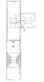
- FIG. 7 two sheets of a paper sheet L2 and a sheet S2 are prepared, and then manufactured in the following steps.
- the numerical value in the figure is the length (mm).
- a perforation is made in the line of f3 of 175 mm from both ends of the sheet L2, and it is folded inward.
- Fold the sheet S2 in half along the line f4.
- (3) Form four mountain fold lines (dashed lines) and six valley fold lines (chain lines).
- Matching the mountain fold line toward the center Fixing both ends of the mountain fold line and the valley fold line of the sheet S2 to the sheet L2 with a water-soluble tape.
- the mountain fold line and the valley fold line of the sheet S2 are bonded to the sheet L2 so as to be parallel to the left-right direction of the stool receiving portion.
- FIG. 8A is a plan view showing a third example of the stool collection sheet according to the present invention
- FIG. 8B is a cross-sectional view taken along the line CC of the stool receiving portion shown in FIG. It is a top view which shows the sheet
- the difference between the stool collection sheet S of the third example and the stool collection sheet S of the first example is the configuration of the folding piece portion 10 provided in the stool receiving portion 2.
- the folding piece portion 10 of the third example has portions that are located at the four corners 7 at the upper end of the toilet receiving portion 2 at the front side edge portion and the rear side edge portion of the upper layer sheet 1. It has a configuration in which a valley is folded and fixed and folded along an inclined line inclined in the center direction of the portion 2.
- the width X1 of the front edge and the rear edge of the toilet receiver 2 in a three-dimensional shape is 16 to 17 cm when the toilet receiver 2 is expanded and inflated on the lower sheet 1 side,
- the length Y1 is 13 to 19 cm, and the width X2 in the front-rear direction of the portion other than the stool receiving portion 2 of the upper layer sheet 1 is 19 cm.
- a bottom portion 8 having a width of 7 cm and a length of 7 cm is formed at the center of the toilet receiving portion 2. Since the other configuration is the same as the first example, the first example is used and the description thereof is omitted.
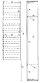
- a paper sheet L3 is prepared as shown in FIG.
- the numerical value in the figure is the length (mm).
- (1) Cut off the hatched portion (2) Fold it along the line f5 and fix it at two places with a stapleless stapler.
- the end is fixed at five places with a stapleless stapler.
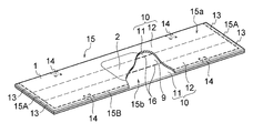
- FIG. 10 is a plan view showing a fourth example of the stool collection sheet according to the present invention
- FIG. 11 is a bottom view of the stool collection sheet shown in FIG. 10
- FIG. 12 is a lower layer sheet of the stool collection part shown in FIG.
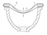
- FIG. 13 is a perspective view of the stool collection sheet shown in FIG. 12, and
- FIGS. 14 and 15 are examples of a method for producing the stool collection sheet S of the fourth example.
- FIG. 16 is a front view showing a state in which the stool collection sheet of the fourth example shown in FIG. 10 is installed on the toilet seat.
- the difference between the stool collection sheet S of the fourth example and the stool collection sheet S of the first example is the configuration of the folding piece 10 provided in the upper layer sheet 1.
- the folding piece portion 10 has the front side edge portion and the rear side edge portion of the upper layer sheet 1 folded back to the back side, and the left and right ends of the folded back side sheet piece portion 11 and front side sheet piece portion 12. The edge is fixed.
- Reference numeral 13 denotes a fixing portion where the left and right edges of the back sheet piece 11 and the front sheet piece 12 are fixed.
- the folding piece 10 has a back sheet piece 11 and a front sheet piece 12 at a substantially intermediate position between the left and right end portions of the upper sheet 1 and the stool receiving portion 2 provided at the center of the upper sheet 1.
- An adhering portion 14 is formed by adhering the folded-back edges.
- the stool receiving part 2 can be formed in a three-dimensional shape swelled on the lower sheet 9 side.
- the folding piece portion 10 has a back sheet piece portion 11 and a front sheet piece portion 12 at a substantially intermediate position between the left and right end portions of the upper layer sheet 1 and the stool receiving portion 2 provided at the center of the upper layer sheet 1. Since the fixing portion 14 is formed by fixing the edges on the folded side, the fixing portion 14 regulates the spread of the back side sheet piece portion 11 and stabilizes the swelling of the stool receiving portion 2. Since the other configuration is the same as the first example, the first example is used and the description thereof is omitted.
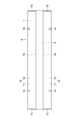
- the rectangular sheet base material 15 is folded in half, and one sheet base material piece 15 a is used as the front side sheet piece portion 12 of the upper layer sheet 1.
- a cut line 16 formed by two perforations parallel to the left-right direction is formed, and a folding piece part 10 provided on the upper sheet 1 with the outside of the two cut lines 16 is provided.
- the back side sheet piece 11 to be configured is used, and the inner side of the two cut lines 16 is a lower layer sheet 9 (see FIG. 14).
- 15A is a fixing portion to which the left and right edges of the sheet base material pieces 15a and 15b are fixed
- 15B is a fixing portion to which the front end edges of the sheet base material pieces 15a and 15b are fixed.
- the fixing portion 15 ⁇ / b> A becomes the fixing portion 13 where the left and right edges of the back-side sheet piece 11 and the front-side sheet piece 12 are fixed.
- the adhering portion 15 ⁇ / b> B forms a folded portion between the front side sheet piece portion 12 of the upper layer sheet 1 and the back side sheet piece portion 11 folded back on the back side of the front side sheet piece portion 12. In this way, the folded piece 10 is formed on the upper sheet 1.
- the folding piece 10 has a back sheet piece 11 and a front sheet piece 12 at a substantially intermediate position between the left and right end portions of the upper sheet 1 and the stool receiving portion 2 provided at the center of the upper sheet 1.
- the edge portions on the folding side are fixed to each other to form the fixing portion 14 (see FIG. 15).
- the stool receiving part 2 is formed into a three-dimensional shape swelled to the lower layer sheet 9 side (FIG. 12, (See FIG. 13). Then, the folding piece portion 10 has a back sheet piece portion 11 and a front sheet piece portion 12 at a substantially intermediate position between the left and right end portions of the upper layer sheet 1 and the stool receiving portion 2 provided at the center of the upper layer sheet 1. Since the fixing portion 14 is formed by fixing the folded-back edges, the spreading of the back side sheet piece portion 11 is restricted by the fixing portion 14, and the stool receiving portion 2 can be formed in a stable three-dimensional shape.
- the toilet seat is first set up vertically, or the toilet seat is lifted from the toilet bowl by hand, The toilet seat is passed through a gap formed between the upper layer sheet 1 and the lower layer sheet 9 constituting the sheet S, the toilet seat sheet S is installed on the back side, and then the toilet seat is placed on the toilet.
- the stool receiving part 2 is adjusted so that it is easy to receive stool, the back sheet piece 11 of the folding piece part 10 is raised on the front side of the front sheet piece 12, and the stool receiving part 2 is placed on the lower sheet 9 side. Expand to form a three-dimensional shape that swells (see FIG. 16). Since others are the same as that of the 1st example, the 1st example is used and the explanation is omitted.
Landscapes
- Health & Medical Sciences (AREA)
- Life Sciences & Earth Sciences (AREA)
- Engineering & Computer Science (AREA)
- General Health & Medical Sciences (AREA)
- Pathology (AREA)
- Public Health (AREA)
- Biomedical Technology (AREA)
- Molecular Biology (AREA)
- Chemical & Material Sciences (AREA)
- Heart & Thoracic Surgery (AREA)
- Veterinary Medicine (AREA)
- Animal Behavior & Ethology (AREA)
- Surgery (AREA)
- Medical Informatics (AREA)
- General Physics & Mathematics (AREA)
- Biochemistry (AREA)
- Physics & Mathematics (AREA)
- Immunology (AREA)
- Analytical Chemistry (AREA)
- Hematology (AREA)
- Food Science & Technology (AREA)
- Medicinal Chemistry (AREA)
- Urology & Nephrology (AREA)
- Epidemiology (AREA)
- Hydrology & Water Resources (AREA)
- Water Supply & Treatment (AREA)
- Investigating Or Analysing Biological Materials (AREA)
- Sampling And Sample Adjustment (AREA)
- Toilet Supplies (AREA)
- Absorbent Articles And Supports Therefor (AREA)
Abstract
Description
請求項1に記載の発明は、中央に便受け部を設けた上層シートと、前記上層シートの左右両側縁部に延設され、前記上層シートとの間に便座を通すための間隙を形成可能な下層シートからなる筒状の採便シートであって、前記上層シート及び下層シートは水溶性の材質からなり、前記上層シートには、広げることにより前記便受け部を下層シート側に膨らんだ立体形状に形成可能な折り畳み片部を備えていることを特徴としている。
また、上層シートに備えた畳み片部を下層シート側へ押し込み広げることにより便受け部を下層シート側に膨らんだ立体形状に形成することができるので、便受け部に受けた便が便受け部から落ちることを防ぐことができる。
また、上層シート及び下層シートは水溶性の材質からなるので、採便後はそのまま水洗便器へ流すことができる。
(第1例)
図1(a)は、本発明に係る採便シートの第1例を示す平面図、(b)は(a)に示す便受け部の左右方向のA-A断面図、図2は図1に示す採便シートの便受け部を下層シート側に膨らませ、立体形状を形成させた状態を示す斜視図、図3は図1に示す第1例の採便シートの作製に用いる紙製のシートを示す平面図、図4は図1に示す第1例の採便シートを便座に設置した状態を示す正面図、図5は図1に示す第1例の採便シートを便座に設置した状態を示す平面図である。
立体形状に形成された便受け部2の前方側縁部と後方側縁部の幅X1は8~19cmであり、左右の長さY1は12~16cmである。X1に関しては、前後方向に力を加えることによりさらに短くなる。
第1例で用いた水溶性の紙の品質性能は以下のとおりである。
(1)紙の厚み 0.06mm/枚
(2)坪量 25g/m2
(3)引張強度(gf/25mm)
MD 2750g
CD 750g
(4)ほぐれ易さ(秒) 30秒以下
まず、図3に示すように紙製のシートL1を準備したうえで以下の工程で作製する。図中の数値は長さ(mm)である。
(1)シートL1の斜線部をカットして除去する。f2にミシン目を入れる。
(2)f1の線でたたみ、便受け部を2層とし、便受け部の端2か所を針なしステープラーで固着する。
(3)山折り線(一点鎖線)を4本、谷折り線(鎖線)を4本形成する。
(4)中心方向に向かって山折り線を合わせる。
(5)水溶性テープで山折り線及び谷折り線の両端を固着する。
(6)f2の線で折り畳み、端部同士を針なしステープラーで固着する。
次に、便受け部2が便を受けやすい位置となるように調整し、上層シート1全体を軽く下層方向に押し込み、折り畳み片部10を広げて便受け部2が下層シート9側に膨らんだ立体形状を形成するように展開する(図4、図5参照。)。
図6(a)は、本発明に係る採便シートの第2例を示す平面図、(b)は(a)に示す便受け部の前後方向のB-B断面図、図7は図6に示す第2例の採便シートの作製に用いる紙製のシートを示す平面図である。
第2例の採便シートSと第1例の採便シートSとの異なる点は、便受け部2に設けられた折り畳み片部10の構成である。第2例の畳み片部10は、図6に示すように、便受け部2の左右方向に対して平行に設けられている山折り線3と谷折り線4で折り畳まれた構成となっている。
立体形状に形成された状態における便受け部2の前方側縁部と後方側縁部の幅X1は12~15cmであり、左右の長さY1は13~19cmである。
その他の構成は第1例と同様なので、第1例を援用し、その説明を省略する。
まず、図7に示すように紙製のシートL2、シートS2の2枚のシートを準備したうえで以下の工程で作製する。図中の数値は長さ(mm)である。
(1)シートL2の両端から175mmのf3の線にミシン目を入れ、内側に折る。
(2)シートS2をf4の線で半分に折る
(3)山折り線(一点鎖線)を4本、谷折り線(鎖線)を6本形成する。
(4)中心に向かって山折り線を合わせる
(5)シートS2の山折り線及び谷折り線の両端をシートL2に水溶性テープで固着する。ここで、シートS2の山折り線及び谷折り線は便受け部の左右方向と平行になるようにシートL2に接着する。
図8(a)は、本発明に係る採便シートの第3例を示す平面図、(b)は(a)に示す便受け部の左右方向のC-C断面図、図9は図8に示す第3例の採便シートの作製に用いる紙製のシートを示す平面図である。
第3例の採便シートSと第1例の採便シートSとの異なる点は、便受け部2に設けられた折り畳み片部10の構成である。
第3例の畳み片部10は、図8に示すように、上層シート1の前方側縁部と後方側縁部における便受け部2の上端の4つの隅7に位置する部分が、便受け部2の中心方向に傾斜する傾斜線に沿って谷折りされ固着され折り畳まれた構成となっている。
その他の構成は第1例と同様なので、第1例を援用し、その説明を省略する。
まず、図9に示すように紙製のシートL3を準備したうえで以下の工程で作製する。図中の数値は長さ(mm)である。
(1)斜線部を切り取る
(2)f5の線で折りたたみ、針なしステープラーで2か所固着する。
(3)f6の線にミシン目を入れ、折りたたむ。
(4)端を針なしステープラーで5か所固着する。
(5)中心の対角線を折る(2本)。
(6)中心の正方形の周囲を折る(4本)。
(7)立体形状となるように折り、4つの隅を針なしステープラーで固着する。
図10は本発明に係る採便シートの第4例を示す平面図、図11は図10に示す採便シートの底面図、図12は図10に示す採便シートの便受け部を下層シート側に膨らませ、立体形状を形成させた状態を示す平面図、図13は図12に示す採便シートの斜視図、図14、図15は第4例の採便シートSの作製方法の一例を示す工程図、図16は図10に示す第4例の採便シートを便座に設置した状態を示す正面図である。
第4例の採便シートSと第1例の採便シートSとの異なる点は、上層シート1に備えられた折り畳み片部10の構成である。
さらに、折り畳み片部10には、上層シート1の左右の端部と上層シート1の中央に設けられた便受け部2との概ね中間位置で、裏側シート片部11と表側シート片部12の折り返し側の縁部同士を固着した固着部14が形成されている。
そして、折り畳み片部10には、上層シート1の左右の端部と上層シート1の中央に設けられた便受け部2との概ね中間位置で、裏側シート片部11と表側シート片部12の折り返し側の縁部同士を固着した固着部14が形成されているので、固着部14が裏側シート片部11の広がりを規制し、便受け部2の膨らみを安定させる。
その他の構成は第1例と同様なので、第1例を援用し、その説明を省略する。
まず、長方形のシート基材15を2つ折りし、一方のシート基材片15aを上層シート1の表側シート片部12とする。
他方のシート基材片15bには、左右方向に平行な2本のミシン目で形成した切り込み線16を形成し、2本の切り込み線16の外側を上層シート1に備えた折り畳み片部10を構成する裏側シート片部11とするとともに、2本の切り込み線16の内側を下層シート9とする(図14参照。)。
そして、折り畳み片部10には、上層シート1の左右の端部と上層シート1の中央に設けられた便受け部2との概ね中間位置で、裏側シート片部11と表側シート片部12の折り返し側の縁部同士を固着した固着部14が形成されているので、固着部14により裏側シート片部11の広がりが規制され、便受け部2の安定した立体形状に形成することができる。
その他は、第1例と同様なので、第1例を援用し、その説明を省略する。
1 上層シート
2 便受け部
3 山折り線
3a 山折り線の端部
4 谷折り線
4a 谷折り線の端部
5 水溶性テープ
6 切り込み部
7 便受け部の上端の隅
8 底部
9 下層シート
10 折り畳み片部
10a 折片
11 裏側シート片部
12 表側シート片部
13、14 固着部
15 シート基材
15a、15b シート基材片
15A、15B 固着部
16 切り込み線
20 便受け部の中心
X1 前方側縁部と後方側縁部の幅
X2 上層シートの便受け部以外の部分の幅
Y1 便受け部における左右方向の長さ
Y2 上層シートの左右方向の長さ
Claims (8)
- 中央に便受け部を設けた上層シートと、前記上層シートの左右両側縁部に延設され、前記上層シートとの間に便座を通すための間隙を形成可能な下層シートからなる筒状の採便シートであって、前記上層シート及び下層シートは水溶性の材質からなり、前記上層シートには、広げることにより前記便受け部を下層シート側に膨らんだ立体形状に形成可能な折り畳み片部を備えていることを特徴とする採便シート。
- 前記水溶性の材質からなる前記上層シート及び下層シートは、水溶性の紙からなることを特徴とする請求項1に記載の採便シート。
- 前記上層シートに備えた前記折り畳み片部は、前記上層シートの前記便受け部に山折り線と谷折り線が設けられ、前記山折り線と前記谷折り線の端部が固着された構成となっており、前記山折り線と前記谷折り線に折られた折片を前記下層シート側へ広げることにより、前記便受け部を前記下層シート側に膨らんだ立体形状に形成可能としたことを特徴とする請求項1または2に記載の採便シート。
- 前記上層シートの前記便受け部に設けられた山折り線と谷折り線は互いに平行であることを特徴とする請求項3に記載の採便シート。
- 前記上層シートの前記便受け部に設けられた前記山折り線と前記谷折り線は、前記便受け部の前後方向に対して平行に設けられていることを特徴とする請求項4に記載の採便シート。
- 前記上層シートの前記便受け部に設けられた前記山折り線と前記谷折り線は、前記便受け部の左右方向に対して平行に設けられていることを特徴とする請求項4に記載の採便シート。
- 前記上層シートに備えた前記折り畳み片部は、前記上層シートの前方側縁部と後方側縁部が裏面側に折り返され、折り返された裏側シート片部と表側シート片部との左右の端縁が固着された構成となっており、前記裏側シート片部を表側シート片部の表側に起こして広げることにより、前記便受け部を下層シート側に膨らんだ立体形状に形成可能としたことを特徴とする請求項1または2に記載の採便シート。
- 前記上層シートと前記下層シートは、長方形のシート基材を2つ折りした2片のシート基材片からなり、一方の前記シート基材片を前記上層シートの前記表側シート片部とし、他方の前記シート基材片には、左右方向に平行な2本の切り込み線を形成し、2本の前記切り込み線の外側を前記上層シートに備えた前記折り畳み片部を構成する前記裏側シート片部とするとともに、2本の前記切り込み線の内側を前記下層シートとし、前記シート基材を2つ折りした2片の前記シート基材片を重ね、重ねた2片の前記シート基材片の開放された3方の端縁を固着したことを特徴とする請求項7に記載の採便シート。
Priority Applications (6)
| Application Number | Priority Date | Filing Date | Title |
|---|---|---|---|
| JP2018530343A JP6924444B2 (ja) | 2016-07-26 | 2017-07-26 | 採便シート |
| KR1020197003972A KR102521462B1 (ko) | 2016-07-26 | 2017-07-26 | 채변 시트 |
| US16/320,312 US11272907B2 (en) | 2016-07-26 | 2017-07-26 | Feces sampling sheet |
| EP17834392.7A EP3492914B1 (en) | 2016-07-26 | 2017-07-26 | Feces sampling sheet |
| AU2017303620A AU2017303620A1 (en) | 2016-07-26 | 2017-07-26 | Feces sampling sheet |
| CN201780059426.6A CN109791135B (zh) | 2016-07-26 | 2017-07-26 | 采便薄片 |
Applications Claiming Priority (2)
| Application Number | Priority Date | Filing Date | Title |
|---|---|---|---|
| JP2016-146168 | 2016-07-26 | ||
| JP2016146168 | 2016-07-26 |
Publications (1)
| Publication Number | Publication Date |
|---|---|
| WO2018021390A1 true WO2018021390A1 (ja) | 2018-02-01 |
Family
ID=61016037
Family Applications (1)
| Application Number | Title | Priority Date | Filing Date |
|---|---|---|---|
| PCT/JP2017/026993 Ceased WO2018021390A1 (ja) | 2016-07-26 | 2017-07-26 | 採便シート |
Country Status (8)
| Country | Link |
|---|---|
| US (1) | US11272907B2 (ja) |
| EP (1) | EP3492914B1 (ja) |
| JP (1) | JP6924444B2 (ja) |
| KR (1) | KR102521462B1 (ja) |
| CN (1) | CN109791135B (ja) |
| AU (1) | AU2017303620A1 (ja) |
| TW (1) | TWI731127B (ja) |
| WO (1) | WO2018021390A1 (ja) |
Families Citing this family (3)
| Publication number | Priority date | Publication date | Assignee | Title |
|---|---|---|---|---|
| WO2017187657A1 (ja) * | 2016-04-26 | 2017-11-02 | 株式会社高橋型精 | 採便具および採便具製造装置 |
| WO2020210273A1 (en) * | 2019-04-09 | 2020-10-15 | University Of South Alabama | Foldable stool specimen collection device |
| US12336672B2 (en) * | 2022-12-31 | 2025-06-24 | Ophelia Denise Adams | Toilet seat trap |
Citations (5)
| Publication number | Priority date | Publication date | Assignee | Title |
|---|---|---|---|---|
| US5337426A (en) * | 1990-11-21 | 1994-08-16 | Beckman Instruments, Inc. | Disposable sample collection device |
| JPH076760U (ja) * | 1993-06-30 | 1995-01-31 | 丸ノ内紙工株式会社 | 検便用採便具 |
| US5463782A (en) * | 1994-11-21 | 1995-11-07 | Eric V. Carlson | Foldable stool sample collection device |
| JP2015135296A (ja) * | 2014-01-18 | 2015-07-27 | 株式会社▲高▼橋型精 | 採便具 |
| JP3200606U (ja) * | 2015-08-13 | 2015-10-22 | 光一郎 町野 | 採便用シート |
Family Cites Families (17)
| Publication number | Priority date | Publication date | Assignee | Title |
|---|---|---|---|---|
| US3588921A (en) * | 1969-10-09 | 1971-06-29 | Theodore C Nagel | Toilet mounted disposable stool specimen collector |
| US4309782A (en) * | 1980-09-11 | 1982-01-12 | Esteban Paulin | Device for collecting fecal specimens |
| DE3905572A1 (de) * | 1989-02-23 | 1990-08-30 | Polykarp Voelk Maschinenbau | Endlos-papiermanschette |
| JPH076760A (ja) | 1993-06-18 | 1995-01-10 | Shin Kobe Electric Mach Co Ltd | アルカリ蓄電池用焼結式陽極板およびその製造法 |
| JPH07270403A (ja) | 1994-03-30 | 1995-10-20 | Fujisawa Pharmaceut Co Ltd | 採便用シート |
| FR2740672B1 (fr) * | 1995-11-08 | 1997-12-26 | Le Fourn Gilbert | Sac jetable pour le recueil de matieres fecales |
| JP3566810B2 (ja) | 1996-08-28 | 2004-09-15 | 栄研化学株式会社 | 採便用便受けシート及び採便方法 |
| JP3292815B2 (ja) * | 1997-02-10 | 2002-06-17 | 株式会社松野製紙 | 携帯用便器 |
| JP2000352093A (ja) * | 1999-06-11 | 2000-12-19 | Daiichi Shiko Kk | 便採取用シート |
| JP2004085520A (ja) | 2002-08-28 | 2004-03-18 | Yoshihiro Maekawa | 検便用採取具 |
| EP1596721B1 (de) * | 2003-02-25 | 2007-08-08 | Jürgen Rathenberg | Aufnahmehilfe für wc-toilettenbecken |
| JP2005017252A (ja) | 2003-06-30 | 2005-01-20 | Nittoku Kk | 採便用シート及び採便方法 |
| PT103553B (pt) * | 2006-08-17 | 2007-08-09 | Luis Vargas | Método de redução e controlo ds tensões envolvidas na colapsibilidade de uma embalagem totalmente colapsável |
| EP2552321B1 (en) * | 2010-04-02 | 2014-03-12 | Antonius Henricus Petrus Bosch | Auxiliary device for receiving fecal matter |
| RU2584648C2 (ru) * | 2012-01-09 | 2016-05-20 | Кйоунг-Хун КИМ | Приемник каловых масс человека |
| NL2008396C2 (en) * | 2012-03-01 | 2013-09-03 | Fubusc B V | Device for collecting faeces, a method for manufacturing and use of such a device. |
| FR3025716B1 (fr) * | 2014-09-15 | 2023-04-21 | M3At Sa | Article pour recueillir l'urine et les selles d'un utilisateur |
-
2017
- 2017-07-26 AU AU2017303620A patent/AU2017303620A1/en not_active Abandoned
- 2017-07-26 WO PCT/JP2017/026993 patent/WO2018021390A1/ja not_active Ceased
- 2017-07-26 KR KR1020197003972A patent/KR102521462B1/ko active Active
- 2017-07-26 EP EP17834392.7A patent/EP3492914B1/en active Active
- 2017-07-26 JP JP2018530343A patent/JP6924444B2/ja active Active
- 2017-07-26 TW TW106125160A patent/TWI731127B/zh not_active IP Right Cessation
- 2017-07-26 CN CN201780059426.6A patent/CN109791135B/zh active Active
- 2017-07-26 US US16/320,312 patent/US11272907B2/en not_active Expired - Fee Related
Patent Citations (5)
| Publication number | Priority date | Publication date | Assignee | Title |
|---|---|---|---|---|
| US5337426A (en) * | 1990-11-21 | 1994-08-16 | Beckman Instruments, Inc. | Disposable sample collection device |
| JPH076760U (ja) * | 1993-06-30 | 1995-01-31 | 丸ノ内紙工株式会社 | 検便用採便具 |
| US5463782A (en) * | 1994-11-21 | 1995-11-07 | Eric V. Carlson | Foldable stool sample collection device |
| JP2015135296A (ja) * | 2014-01-18 | 2015-07-27 | 株式会社▲高▼橋型精 | 採便具 |
| JP3200606U (ja) * | 2015-08-13 | 2015-10-22 | 光一郎 町野 | 採便用シート |
Non-Patent Citations (1)
| Title |
|---|
| See also references of EP3492914A4 * |
Also Published As
| Publication number | Publication date |
|---|---|
| US20190239862A1 (en) | 2019-08-08 |
| CN109791135A (zh) | 2019-05-21 |
| KR20190031499A (ko) | 2019-03-26 |
| KR102521462B1 (ko) | 2023-04-12 |
| CN109791135B (zh) | 2022-06-03 |
| JP6924444B2 (ja) | 2021-08-25 |
| EP3492914A4 (en) | 2020-03-04 |
| AU2017303620A1 (en) | 2019-02-14 |
| EP3492914B1 (en) | 2024-05-22 |
| TWI731127B (zh) | 2021-06-21 |
| JPWO2018021390A1 (ja) | 2019-06-20 |
| EP3492914A1 (en) | 2019-06-05 |
| TW201819910A (zh) | 2018-06-01 |
| US11272907B2 (en) | 2022-03-15 |
Similar Documents
| Publication | Publication Date | Title |
|---|---|---|
| WO2018021390A1 (ja) | 採便シート | |
| NL2008396C2 (en) | Device for collecting faeces, a method for manufacturing and use of such a device. | |
| JP2020024197A (ja) | 排泄物採取具 | |
| JP6908918B2 (ja) | 排泄物採取具 | |
| US20070044213A1 (en) | Flushable urination assisting device | |
| KR101606886B1 (ko) | 분변 시료 채취용 위생용기 | |
| JPH07270403A (ja) | 採便用シート | |
| KR101640378B1 (ko) | 채변지 | |
| JP3139911U (ja) | 採便シート | |
| JP3200606U (ja) | 採便用シート | |
| JP5612784B1 (ja) | 月経時用シート付き携帯尿器 | |
| JP2004085520A (ja) | 検便用採取具 | |
| TWI657782B (zh) | 拋棄式容置袋 | |
| JPH0731175Y2 (ja) | 検便用大便の採取用具 | |
| TWM560898U (zh) | 拋棄式容置袋 | |
| JP2018017618A (ja) | 採便シート | |
| JP2000352093A (ja) | 便採取用シート | |
| JP2021016757A (ja) | 尿拭きパッド | |
| CN215285903U (zh) | 一种可用于收集粪便的粪便样本采集装置包装盒 | |
| CN214538586U (zh) | 粪便收集装置 | |
| JP2020049196A (ja) | 介護用尿とりパッド | |
| WO2025018411A1 (ja) | 採尿具 | |
| JPH095318A (ja) | 大便保持容器 | |
| JP3201011U (ja) | マットレス又はベッドにおける排泄物処理ボックス | |
| KR101330465B1 (ko) | 일회용 위생 변기시트 커버 |
Legal Events
| Date | Code | Title | Description |
|---|---|---|---|
| 121 | Ep: the epo has been informed by wipo that ep was designated in this application |
Ref document number: 17834392 Country of ref document: EP Kind code of ref document: A1 |
|
| ENP | Entry into the national phase |
Ref document number: 2018530343 Country of ref document: JP Kind code of ref document: A |
|
| NENP | Non-entry into the national phase |
Ref country code: DE |
|
| ENP | Entry into the national phase |
Ref document number: 20197003972 Country of ref document: KR Kind code of ref document: A |
|
| ENP | Entry into the national phase |
Ref document number: 2017303620 Country of ref document: AU Date of ref document: 20170726 Kind code of ref document: A |
|
| ENP | Entry into the national phase |
Ref document number: 2017834392 Country of ref document: EP Effective date: 20190226 |