WO2018021434A1 - 玉軸受 - Google Patents
玉軸受 Download PDFInfo
- Publication number
- WO2018021434A1 WO2018021434A1 PCT/JP2017/027105 JP2017027105W WO2018021434A1 WO 2018021434 A1 WO2018021434 A1 WO 2018021434A1 JP 2017027105 W JP2017027105 W JP 2017027105W WO 2018021434 A1 WO2018021434 A1 WO 2018021434A1
- Authority
- WO
- WIPO (PCT)
- Prior art keywords
- outer ring
- ball bearing
- raceway groove
- ring raceway
- ball
- Prior art date
- Legal status (The legal status is an assumption and is not a legal conclusion. Google has not performed a legal analysis and makes no representation as to the accuracy of the status listed.)
- Ceased
Links
Images




Classifications
-
- F—MECHANICAL ENGINEERING; LIGHTING; HEATING; WEAPONS; BLASTING
- F16—ENGINEERING ELEMENTS AND UNITS; GENERAL MEASURES FOR PRODUCING AND MAINTAINING EFFECTIVE FUNCTIONING OF MACHINES OR INSTALLATIONS; THERMAL INSULATION IN GENERAL
- F16C—SHAFTS; FLEXIBLE SHAFTS; ELEMENTS OR CRANKSHAFT MECHANISMS; ROTARY BODIES OTHER THAN GEARING ELEMENTS; BEARINGS
- F16C33/00—Parts of bearings; Special methods for making bearings or parts thereof
- F16C33/30—Parts of ball or roller bearings
- F16C33/66—Special parts or details in view of lubrication
- F16C33/6637—Special parts or details in view of lubrication with liquid lubricant
- F16C33/6681—Details of distribution or circulation inside the bearing, e.g. grooves on the cage or passages in the rolling elements
-
- F—MECHANICAL ENGINEERING; LIGHTING; HEATING; WEAPONS; BLASTING
- F16—ENGINEERING ELEMENTS AND UNITS; GENERAL MEASURES FOR PRODUCING AND MAINTAINING EFFECTIVE FUNCTIONING OF MACHINES OR INSTALLATIONS; THERMAL INSULATION IN GENERAL
- F16C—SHAFTS; FLEXIBLE SHAFTS; ELEMENTS OR CRANKSHAFT MECHANISMS; ROTARY BODIES OTHER THAN GEARING ELEMENTS; BEARINGS
- F16C33/00—Parts of bearings; Special methods for making bearings or parts thereof
- F16C33/30—Parts of ball or roller bearings
- F16C33/66—Special parts or details in view of lubrication
- F16C33/6637—Special parts or details in view of lubrication with liquid lubricant
- F16C33/6659—Details of supply of the liquid to the bearing, e.g. passages or nozzles
- F16C33/6662—Details of supply of the liquid to the bearing, e.g. passages or nozzles the liquid being carried by air or other gases, e.g. mist lubrication
-
- F—MECHANICAL ENGINEERING; LIGHTING; HEATING; WEAPONS; BLASTING
- F16—ENGINEERING ELEMENTS AND UNITS; GENERAL MEASURES FOR PRODUCING AND MAINTAINING EFFECTIVE FUNCTIONING OF MACHINES OR INSTALLATIONS; THERMAL INSULATION IN GENERAL
- F16C—SHAFTS; FLEXIBLE SHAFTS; ELEMENTS OR CRANKSHAFT MECHANISMS; ROTARY BODIES OTHER THAN GEARING ELEMENTS; BEARINGS
- F16C19/00—Bearings with rolling contact, for exclusively rotary movement
- F16C19/02—Bearings with rolling contact, for exclusively rotary movement with bearing balls essentially of the same size in one or more circular rows
- F16C19/14—Bearings with rolling contact, for exclusively rotary movement with bearing balls essentially of the same size in one or more circular rows for both radial and axial load
- F16C19/16—Bearings with rolling contact, for exclusively rotary movement with bearing balls essentially of the same size in one or more circular rows for both radial and axial load with a single row of balls
-
- F—MECHANICAL ENGINEERING; LIGHTING; HEATING; WEAPONS; BLASTING
- F16—ENGINEERING ELEMENTS AND UNITS; GENERAL MEASURES FOR PRODUCING AND MAINTAINING EFFECTIVE FUNCTIONING OF MACHINES OR INSTALLATIONS; THERMAL INSULATION IN GENERAL
- F16C—SHAFTS; FLEXIBLE SHAFTS; ELEMENTS OR CRANKSHAFT MECHANISMS; ROTARY BODIES OTHER THAN GEARING ELEMENTS; BEARINGS
- F16C19/00—Bearings with rolling contact, for exclusively rotary movement
- F16C19/02—Bearings with rolling contact, for exclusively rotary movement with bearing balls essentially of the same size in one or more circular rows
- F16C19/14—Bearings with rolling contact, for exclusively rotary movement with bearing balls essentially of the same size in one or more circular rows for both radial and axial load
- F16C19/18—Bearings with rolling contact, for exclusively rotary movement with bearing balls essentially of the same size in one or more circular rows for both radial and axial load with two or more rows of balls
- F16C19/181—Bearings with rolling contact, for exclusively rotary movement with bearing balls essentially of the same size in one or more circular rows for both radial and axial load with two or more rows of balls with angular contact
-
- F—MECHANICAL ENGINEERING; LIGHTING; HEATING; WEAPONS; BLASTING
- F16—ENGINEERING ELEMENTS AND UNITS; GENERAL MEASURES FOR PRODUCING AND MAINTAINING EFFECTIVE FUNCTIONING OF MACHINES OR INSTALLATIONS; THERMAL INSULATION IN GENERAL
- F16C—SHAFTS; FLEXIBLE SHAFTS; ELEMENTS OR CRANKSHAFT MECHANISMS; ROTARY BODIES OTHER THAN GEARING ELEMENTS; BEARINGS
- F16C33/00—Parts of bearings; Special methods for making bearings or parts thereof
- F16C33/30—Parts of ball or roller bearings
- F16C33/58—Raceways; Race rings
- F16C33/583—Details of specific parts of races
-
- F—MECHANICAL ENGINEERING; LIGHTING; HEATING; WEAPONS; BLASTING
- F16—ENGINEERING ELEMENTS AND UNITS; GENERAL MEASURES FOR PRODUCING AND MAINTAINING EFFECTIVE FUNCTIONING OF MACHINES OR INSTALLATIONS; THERMAL INSULATION IN GENERAL
- F16C—SHAFTS; FLEXIBLE SHAFTS; ELEMENTS OR CRANKSHAFT MECHANISMS; ROTARY BODIES OTHER THAN GEARING ELEMENTS; BEARINGS
- F16C33/00—Parts of bearings; Special methods for making bearings or parts thereof
- F16C33/30—Parts of ball or roller bearings
- F16C33/58—Raceways; Race rings
- F16C33/583—Details of specific parts of races
- F16C33/585—Details of specific parts of races of raceways, e.g. ribs to guide the rollers
-
- F—MECHANICAL ENGINEERING; LIGHTING; HEATING; WEAPONS; BLASTING
- F16—ENGINEERING ELEMENTS AND UNITS; GENERAL MEASURES FOR PRODUCING AND MAINTAINING EFFECTIVE FUNCTIONING OF MACHINES OR INSTALLATIONS; THERMAL INSULATION IN GENERAL
- F16C—SHAFTS; FLEXIBLE SHAFTS; ELEMENTS OR CRANKSHAFT MECHANISMS; ROTARY BODIES OTHER THAN GEARING ELEMENTS; BEARINGS
- F16C19/00—Bearings with rolling contact, for exclusively rotary movement
- F16C19/02—Bearings with rolling contact, for exclusively rotary movement with bearing balls essentially of the same size in one or more circular rows
- F16C19/14—Bearings with rolling contact, for exclusively rotary movement with bearing balls essentially of the same size in one or more circular rows for both radial and axial load
- F16C19/16—Bearings with rolling contact, for exclusively rotary movement with bearing balls essentially of the same size in one or more circular rows for both radial and axial load with a single row of balls
- F16C19/163—Bearings with rolling contact, for exclusively rotary movement with bearing balls essentially of the same size in one or more circular rows for both radial and axial load with a single row of balls with angular contact
-
- F—MECHANICAL ENGINEERING; LIGHTING; HEATING; WEAPONS; BLASTING
- F16—ENGINEERING ELEMENTS AND UNITS; GENERAL MEASURES FOR PRODUCING AND MAINTAINING EFFECTIVE FUNCTIONING OF MACHINES OR INSTALLATIONS; THERMAL INSULATION IN GENERAL
- F16C—SHAFTS; FLEXIBLE SHAFTS; ELEMENTS OR CRANKSHAFT MECHANISMS; ROTARY BODIES OTHER THAN GEARING ELEMENTS; BEARINGS
- F16C2322/00—Apparatus used in shaping articles
- F16C2322/39—General buildup of machine tools, e.g. spindles, slides, actuators
Definitions
- the present invention relates to a ball bearing, and more particularly to an outer ring oil supply type ball bearing.
- ⁇ Grease lubrication, oil-air lubrication, oil mist lubrication, etc. are listed as rolling bearing lubrication methods often used for machine tool spindles.
- oil-air lubrication is employed in the region of high speed rotation (dmn 800,000 or more).
- high-pressure air and fine oil particles are supplied into the bearing from the side surface of the bearing by using an oil supply nozzle top 101 inserted into the radial through hole 102a of 102.
- the vibration will increase.
- the air curtain generated by the high-speed rotation (the air curtain is a wall of the high-speed air flow in the circumferential direction generated by the friction between the air and the outer surface of the inner ring rotating at high speed).
- the supply of oil particles from the nozzle is obstructed, and as a result, it is difficult to reliably supply the lubricating oil into the bearing.
- conventional oil-air lubrication is superior to grease lubrication in terms of lubricity under high-speed rotation, the response has become important as the speed increases.
- an oil groove 112 is formed in the circumferential direction of the outer peripheral surface of the outer ring 111, and at the same axial position as the oil groove 112, the oil groove 112 is directed in the radial direction.
- an outer ring oil supply type bearing 110 having an oil hole 113 formed therein see, for example, Patent Document 1.
- an outer ring oil supply type bearing even when the bearing is used at high speed rotation, the supply of oil particles is not hindered by the air curtain. Therefore, a stable spindle can be used even at high speed.
- FIG. 10 shows a schematic view of the main shaft in the case of oil-air lubrication using the nozzle top 101 and oil-air lubrication of the outer ring oil supply specification.
- the upper half of FIG. 10 is an oil / air lubrication spindle 120 with an outer ring lubrication specification, and the lower half is an oil / air lubrication spindle 120 A using a nozzle top 101.
- reference numeral 121 denotes a rotating shaft
- reference numeral 122 denotes a motor rotor that is fitted to the rotating shaft 121.
- a spacer having a certain axial length or more is required to supply the lubricating oil from the side surface of the bearing 100.
- the nozzle top can be reduced and the structure of the spacer can be simplified, and the axial length of the spacer 123 is used by a nozzle piece. Compared to the specification, it can be shortened.
- the outer ring oil supply type bearing has many advantages compared to the conventional side surface oil supply type bearing.
- the lubricating oil is supplied at once to the vicinity of the contact ellipse. And damage due to large bearing heat generation may occur.
- an object of the present invention is to appropriately set the axial position of the radial hole provided in the outer ring of the outer ring oil-filled bearing according to the use application of the bearing.
- an object of the present invention is to provide a ball bearing capable of obtaining better lubricating performance and rotational performance.
- a ball bearing lubricated with lubricating oil The outer ring has at least one radial hole penetrating in a radial direction from an outer peripheral surface to an inner peripheral surface thereof, The axial position of the center line of the radial hole is inferior to the rotation axis of the ball by a straight line connecting from the intersection of the center line of the radial hole and the surface of the ball to the center of the ball.
- the inner peripheral surface of the outer ring has an inclined portion that gradually decreases in diameter from an axial end surface toward the outer ring raceway groove, and a rotational axis center of the ball bearing that connects the inclined portion and the outer ring raceway groove. Having a counter bore with a straight portion parallel to the line; The ball bearing according to (1), wherein all the inner diameter side openings of the radial holes are located in the inclined portion.
- the inner peripheral surface of the outer ring has an inclined portion that gradually decreases in diameter from an axial end surface toward the outer ring raceway groove, and a rotational axis center of the ball bearing that connects the inclined portion and the outer ring raceway groove. Having a counter bore with a straight portion parallel to the line;
- the inner peripheral surface of the outer ring has an inclined portion that gradually decreases in diameter from an axial end surface toward the outer ring raceway groove, and a rotational axis center of the ball bearing that connects the inclined portion and the outer ring raceway groove.
- the ball bearing according to (1) wherein all the inner diameter side openings of the radial holes are located in the straight portion.
- the inner peripheral surface of the outer ring has an inclined portion that gradually decreases in diameter from an axial end surface toward the outer ring raceway groove, and a rotational axis center of the ball bearing that connects the inclined portion and the outer ring raceway groove. Having a counter bore with a straight portion parallel to the line; The ball bearing according to (1), wherein an inner diameter side opening of the radial hole is positioned so as to straddle the straight portion and the outer ring raceway groove.
- the inner peripheral surface of the outer ring has an inclined portion that gradually decreases in diameter from an axial end surface toward the outer ring raceway groove, and a rotational axis center of the ball bearing that connects the inclined portion and the outer ring raceway groove. Having a counter bore with a straight portion parallel to the line; All the inner diameter side openings of the radial holes are ball bearings according to (1), which are located in the outer ring raceway groove. (7) The inner peripheral surface of the outer ring has a counter bore with an inclined portion that gradually decreases in diameter from the axial end surface to the outer ring raceway groove, The ball bearing according to (1), wherein all the inner diameter side openings of the radial holes are located in the counterbore.
- the inner peripheral surface of the outer ring has a counter bore with an inclined portion that gradually decreases in diameter from the axial end surface to the outer ring raceway groove, The ball bearing according to (1), wherein an inner diameter side opening of the radial hole is positioned so as to straddle the counter bore and the outer ring raceway groove.
- the inner peripheral surface of the outer ring has a counter bore with an inclined portion that gradually decreases in diameter from the axial end surface to the outer ring raceway groove, The ball bearing according to (1), wherein all of the inner diameter side openings of the radial holes are located in the outer ring raceway groove.
- the outer ring has at least one radial hole penetrating from the outer peripheral surface to the inner peripheral surface in the radial direction, and the axial position of the center line of the radial hole is: 0 ° ⁇ ⁇ 60 °, where ⁇ is an inferior angle formed by a straight line connecting the intersection of the center line of the radial hole and the surface of the ball to the center of the ball with respect to the rotation axis of the ball. Therefore, more stable lubrication performance and rotation performance can be obtained in high-speed applications.
- (A) is a sectional view of a ball bearing in which the axial position of the raceway groove side opening of the radial hole is at point N, and (b) is the axial position of the raceway side opening of the radial hole. Is a cross-sectional view of the ball bearing at point C, and (c) is a cross-sectional view of the ball bearing at which the axial position of the raceway groove side opening of the radial hole is at point D.
- (A) is sectional drawing of a ball bearing in case all the inner diameter side opening parts of a radial hole are located in an inclination part
- (b) is an inner diameter side opening part of a radial hole, and an inclination part and a straight It is sectional drawing of the ball bearing when located so that it may straddle a part
- (c) is sectional drawing of the ball bearing when all the inner diameter side opening parts of a radial direction hole are located in a straight part.
- (A) is a sectional view of a ball bearing when the inner diameter side opening of the radial hole is positioned so as to straddle the straight portion and the outer ring raceway groove
- (b) is the inner diameter side opening of the radial hole.
- a ball bearing 10 As shown in FIG. 1, a ball bearing 10 according to the present embodiment is applied to a high-speed machine tool spindle, and has an inner ring 11 having an arc-shaped inner ring raceway groove 11a on an outer peripheral surface, and an arc-shaped inner peripheral surface.
- An outer ring 12 having an outer ring raceway groove 12a, and a plurality of balls 13 held by a cage 14 and arranged to roll freely between the inner ring raceway groove 11a and the outer ring raceway groove 12a with a predetermined contact angle ⁇ .
- a counter bore 12b having an inclined portion that gradually decreases in diameter from the axial end surface to the outer ring raceway groove 12a is provided, while the inner peripheral surface on the other axial side is provided.
- a groove shoulder 12c is formed on the surface.
- the contact angle ⁇ is set to 15 to 30 ° for applications used on a high-speed machine tool spindle. Further, in order to suppress the adverse effects of expansion of the rotating ring due to centrifugal force during bearing rotation and reduction of the internal radial gap due to the temperature difference between the inner and outer rings, the contact angle ⁇ is more preferably set to 18 ° ⁇ ⁇ 25 °. preferable.
- This ball bearing 10 is an outer ring oil supply type bearing, and the outer ring 12 has a radial hole 15 penetrating in the radial direction from the outer peripheral surface to the inner peripheral surface thereof.
- a concave groove 16 communicating with the radial hole 15 is formed on the outer peripheral surface of the outer ring 12 along the circumferential direction.
- the axial position of the center line X of the radial hole 15 is set as follows.
- the rotation axis s is a rotation axis when the ball 13 rolls on the outer ring raceway groove 12a or the inner ring raceway groove 11a during bearing rotation, and is relative to the straight line representing the contact angle ⁇ . And an angle of approximately 90 °.
- the point represented by N is a point which becomes the pole of the rotational motion of the ball 13.
- point A and point B in the figure are the intersections of a straight line having an angle ⁇ of 60 ° and 30 ° with the rotation axis s of the ball 13 and the surface of the ball 13, respectively.
- the angle ⁇ is a clockwise angle formed by a straight line connecting the intersection of the center line X of the radial hole 15 and the surface of the ball 13 to the center of the ball 13 with respect to the rotation axis s of the ball 13.
- the angle is defined as an angle between the rotation axis s and the straight line.
- the center line X of the radial hole 15 includes its extension line.
- the axial position of the center line X of the radial hole 15 is 0 ° ⁇ ⁇ 60 ° (a range represented by T1 in FIG. 1), more preferably 30 ° ⁇ ⁇ ⁇ 60. It is set so as to be ° (range represented by T2 in FIG. 1). That is, the axial position of the opening on the raceway groove side of the center line X of the radial hole 15 is greater than 0 °, that is, the axial position of the center line X of the radial hole 15 from the point N in FIG.
- the lubricating oil adhering to the surface of the ball 13 when the lubricating oil is supplied is caused by the centrifugal force caused by the revolution of the ball 13 and the centrifugal force caused by the rotation of the ball 13. It is carried into the inner and inner ring raceway grooves 11a.
- the lubricating oil adhered to the groove bottom side from the point N in FIG. It is carried to the equator side (straight side representing the contact angle ⁇ in FIG. 1), that is, into the outer ring raceway groove 12a and the inner ring raceway groove 11a.
- FIG. 2 shows a schematic diagram of the concept of lubricant adhesion on the surface of the ball 13.
- a point C in FIG. 2B and a point D in FIG. 2C represent arbitrary points on the surface side of the ball 13 that are on the groove bottom side and the groove bottom side, respectively.
- L1, L2, and L3 are tangents that pass through the points N, C, and D in the circle representing the surface of the ball 13, respectively.
- the angles formed by the tangent lines L1, L2, L3 and a straight line extending in the radial direction (parallel to the radial cross section) (corresponding to the center line X of the radial hole 15 provided in the outer ring 12) are ⁇ 1, ⁇ 2, and ⁇ 3, respectively. .
- the lubricating oil supplied from the radial hole 15 adheres to the point N and accompanies the rotation of the ball 13 described above. There is a concern that the effect of conveying the lubricating oil by the generated centrifugal force is reduced, leading to a decrease in lubricity. Therefore, by providing the radial hole 15 so that the center line X of the radial hole 15 provided in the outer ring 12 is closer to the groove bottom side than the point N in FIGS. 1 and 2, more stable lubricity and rotation can be achieved. Performance can be obtained.
- the range of 30 ° ⁇ ⁇ ⁇ 60 ° is more preferable is that the peripheral speed of the surface of the ball 13 is small at the point N or in the vicinity thereof (0 ° ⁇ ⁇ 30 °), and the above-described lubricating oil carrying effect is also small. It can be mentioned.
- ⁇ to 30 ° or more (point B in FIG. 1) or more, the portion to which the lubricating oil adheres, that is, the turning radius of the rotating shaft s becomes 1 ⁇ 2 or more of the ball diameter, and an appropriate lubricating oil carrying effect can be obtained.
- the center line X of the radial hole 15 be in the range of 30 ° ⁇ ⁇ 60 °.
- the center line X of the radial hole 15 is in the range of ⁇ > 60 ° in FIG. 1, the ball to which the supplied lubricating oil adheres is compared with the case of 0 ° ⁇ ⁇ 60 °.
- the rotational speed of the surface 13 becomes too large.
- the lubricating oil is supplied to the portion where the rotation speed is high, the ball 13 and the lubricating oil are not adhered to the surface of the ball 13 as compared with the case where the lubricating oil is supplied to the portion where the rotation speed is low. The resistance between them will increase.
- the center line X of the oil hole comes within the above-mentioned range of ⁇ > 60 ° while setting the contact angle as 30 ° as an upper limit, the contact hole ellipse between the radial hole 15 and the outer ring 12 and the ball 13 overlaps. There is a possibility that the contact surface pressure between the vicinity of the flange portion of the radial hole 15 and the ball 13 is increased.
- the center line X of the radial hole 15 is within 0 ° ⁇ ⁇ 60 °, more preferably within 30 ° ⁇ ⁇ ⁇ 60 °.
- the contact angle ⁇ is set to 15 to 30 °, the axial position of the opening on the raceway groove side of the center line X of the radial hole 15 is more anti-contact angle than the bottom of the outer ring groove. It is formed within the range of the side (counter bore side).
- the contact angle ⁇ is set to 30 ° or less.
- the rotation shafts and balls 13 of the inner and outer rings 11 and 12 are set.
- the ball 13 and the inner ring raceway groove 11a and the contact portions of the ball 13 and the outer ring raceway groove 12a become prominent, such as spin slip and gyro slip, and the ball 13 is rotated due to revolution.
- the limit PV value which is an index that becomes the main cause of seizure limit during high-speed rotation of the bearing, is exceeded. Therefore, in the present application, the above-described problems can be avoided by setting the contact angle ⁇ to 30 ° or less.
- dmn value is the product of pitch circle diameter (mm) of rolling elements and bearing rotation speed (min -1 )) of 1.3 million or more (standard operating conditions for recent high-speed spindles)
- the bearing contact angle must be 30 ° or less, and under this condition, the effect of 0 ° ⁇ ⁇ 60 ° can be effectively exhibited.
- FIG. 3 shows an example in which the axial position of the center line X of the radial hole 15 of the present embodiment is set to be in a range of 0 ° ⁇ ⁇ 60 °
- the outer ring inner diameter side opening of the radial hole 15 is formed across the counter bore 12b and the raceway groove 12a.
- the ball 13 and the vicinity of the counter bore in the outer ring raceway groove 12a do not come into contact with each other. Therefore, for the same reason as described above, the assembly workability and handleability are good.
- oil hole opening part exists in the track groove 12a, and is close to the contact part of the ball
- oil supply property is good.
- the above-described oil method can be obtained by paying attention to the work method when assembling the bearing and incorporating the bearing into the main shaft.
- the possibility of burrs at the intersections between the hole openings and the raceway grooves and scratches on the ball surface can be eliminated.
- the diameter of the radial hole 15 is set to 0.5 to 1.5 mm in consideration of the supply capability of the lubricating oil. Moreover, in this embodiment, the radial direction hole 15 has a uniform diameter over radial direction.
- the axial position of the center line X of the radial hole 15 of the outer ring 12 is set such that the center line X and the ball of the radial hole 15 are in relation to the rotation axis s of the ball 13. Since a subordinate angle formed by a straight line connecting the intersection with the surface of 13 and the center O of the ball 13 is ⁇ , the angle is set so that 0 ° ⁇ ⁇ 60 °. More stable lubricity and rotational performance can be obtained in the bearing.
- annular grooves 19 are formed along the circumferential direction on both sides in the axial direction across the concave groove 16.
- a seal member 20 which is an annular elastic member such as an O-ring, may be disposed.
- the angular ball bearing 10a of the present embodiment is different from that of the first embodiment in the shape of the inner peripheral surface of the outer ring 12 on the counter bore side.
- the counter bore 12b is a ball bearing that connects the inclined portion (conical surface) 12b1 that gradually decreases in diameter from the end face in the axial direction toward the raceway groove 12a, and the sloped portion 12b1 and the raceway groove 12a.
- a straight portion (cylindrical surface) 12b2 parallel to the rotation axis center line L (see FIG. 10).
- the outer ring 12 or the inner ring 11 is provided with a portion referred to as an allowance ⁇ r shown in FIG. Therefore, when assembling the angular ball bearing 10a, the outer ring 12 is heated, and the outer ring 12 is expanded by the amount of allowance ⁇ r for assembling.
- the dimension of the allowance ⁇ r is determined by final finish grinding. It is desirable to manage in the order of several tens of ⁇ m.
- the counter bore 12b is composed of only an inclined portion, and an edge is provided between the counter bore 12b and the outer ring raceway groove 12a.
- Dimensional control of the allowance ⁇ r is easy (the dimensional accuracy is easy to obtain during grinding, and since the straight portion is present, the allowance dimension D is easy to measure) and ball scratches are generated during assembly of the bearing. Suppression is possible.
- the axial position of the center line X of the radial hole 15 of the outer ring 12 is the intersection N between the center line X of the radial hole 15 and the surface of the ball 13 with respect to the rotation axis s of the ball 13. Is set to satisfy 0 ° ⁇ ⁇ 60 °, and preferably 30 ° ⁇ ⁇ ⁇ 60 °, where ⁇ is a recessive angle formed by a straight line connecting the center of the ball 13 to the center O of the ball 13.
- ⁇ is a recessive angle formed by a straight line connecting the center of the ball 13 to the center O of the ball 13.
- the axial position of the center line X of the radial hole 15 may be designed at any one of the positions shown in FIGS. 6 (a) to 7 (b).
- the radial hole 15 By providing the radial hole 15 at such a position, it is not necessary to consider burrs or the like of the oil hole opening at the time of raceway groove machining, and the workability of the outer ring raceway groove 12a is good.
- the contact ellipse between the ball 13 and the outer ring raceway groove 12a and the oil hole opening do not overlap when the bearing is incorporated into the main shaft or in use, resulting in generation of ball scratches or an abnormal increase in contact surface pressure. Can be suppressed.
- the outer ring inner diameter side opening of the radial hole 15 is positioned so as to straddle the inclined portion 12b1 and the straight portion 12b2.
- the outer ring inner diameter side opening of the radial hole 15 is all located in the straight portion 12b2.
- the outer ring inner diameter side opening of the radial hole 15 is formed along the inclined portion 12b1 of the counter bore, and the oil supply direction (the rotation axis of the ball bearing)
- the section viewed from the radial direction of the opening is inclined with respect to the direction perpendicular to the center line L).
- the space on the axial end surface side of the opening is wider than the straight portion side, so the pressure on the axial end surface side is weakened, and the air supplied with oil flows to the inclined portion side of the counterbore.
- oil may also flow to the inclined portion side.
- the entire outer ring inner diameter side opening of the radial hole 15 is provided in the straight portion 12b2, so that the section viewed from the radial direction of the opening is in the oil supply direction.
- the parallelism of the oil described above can be ensured because of the parallelism.
- the outer ring inner diameter side opening of the radial hole 15 is positioned so as to straddle the straight portion 12b2 and the outer ring raceway groove 12a.
- a part of the opening of the radial hole 15 overlaps the outer ring raceway groove 12 a, so that the oil supply performance is improved.
- the radial hole only needs to penetrate from the outer peripheral surface to the inner peripheral surface of the outer ring in the radial direction, and is formed along the radial direction (parallel to the radial cut plane) of the present embodiment. Besides, it may be inclined in the circumferential direction.
- the outer ring 12 has one radial hole.
- the outer ring 12 is not limited to this and may have a plurality of radial holes.
- oil mist lubrication may be employed in addition to oil-air lubrication as a method for supplying lubricating oil to the radial hole of the outer ring.
- oil jet lubrication is also possible.
- the radial hole 15 is provided in the outer ring raceway groove 12a and the counter bore 12b.
- the semi-solid grease containing the thickener is contained in the outer ring raceway groove 12a. Will be supplied.
- problems such as an increase in torque and abnormal heat generation occur due to the stirring resistance. In particular, these problems are likely to occur at high speed rotation as in the present embodiment. Therefore, an oil lubrication method for supplying lubricating oil containing no thickener is desirable in the present invention.
- ball bearings of the present invention are not limited to those applied to machine tool spindle devices, but can also be applied as ball bearings for general industrial machines and devices that rotate at high speeds such as motors.
Landscapes
- Engineering & Computer Science (AREA)
- General Engineering & Computer Science (AREA)
- Mechanical Engineering (AREA)
- Rolling Contact Bearings (AREA)
Abstract
アンギュラ玉軸受(10)では、外輪(12)は、その外周面から内周面まで径方向に亘って貫通する少なくとも1つの径方向孔(15)を有し、該径方向孔(15)の中心線(X)の軸方向位置は、玉(13)の自転軸(s)に対して、径方向孔(15)の中心線(X)と玉(13)の表面との交点から玉(13)の中心(O)までを結んだ直線がなす劣角をλとしたとき、0°<λ≦60°となるように設定される。
Description
本発明は、玉軸受に関し、より詳細には、外輪給油型の玉軸受に関する。
近年、工作機械用主軸は切削効率の向上を目指して、高速化の要求が高まっている。また、該主軸には、最近、生産の高効率化のため複雑形状の被加工物を複数の工作機械を使用せず、かつ、段替えなしで加工することが可能な5軸加工機への対応ニーズも出てきている。5軸加工機では、主軸やテーブルが旋回するため、旋回半径の短縮化による省スペース化、あるいは、旋回時のイナーシャ軽減や軽量化による省電力志向等の要求から、スピンドルの軸方向長さの短縮が求められている。
工作機械主軸用として多く採用されている転がり軸受の潤滑方法としては、グリース潤滑、オイルエア潤滑、オイルミスト潤滑などが挙げられる。一般的に、高速回転(dmn80万以上)の領域ではオイルエア潤滑が採用される。従来のオイルエア潤滑としては、図8(a)に示す軸受100の側方に配置された給油用ノズルこま101、又は、図8(b)に示す軸受100の側方に配置された外輪間座102の径方向貫通孔102aに挿入された給油用ノズルこま101を用いて、軸受側面から軸受内部に高圧エア及び微細な油粒を供給する方式が知られている。
この方式では、ノズルこま101等の給油用部品が別に必要であり、スピンドルの部品点数が多くなるため、スピンドル全体のコストアップや管理の手間が増えることにつながる。また、ノズルこま101を使用するため外輪間座の形状やハウジングの構造が複雑になり、スピンドルの設計・加工の手間が増える。さらに、軸受の軸方向側面側にノズルこま101を設置するため、ある程度の間座長さが必要になり、スピンドルの軸方向長さが長くなる。これによって、工作機械自体の大きさが大きくなったり、軸方向長さが増えた分スピンドル重量が重くなり、スピンドルの危険速度(危険速度とは、スピンドルが有する固有振動数から算出した回転速度であり、この危険速度域でスピンドルを回転させると、振動大となってしまう。)が低くなったりする。また、高速回転化に伴い発生するエアカーテン(エアカーテンとは、空気と高速回転する内輪外径表面との摩擦によって発生する円周方向の高速空気流の壁のことである)によって、給油用ノズルからの油粒の供給が阻害され、その結果、軸受内部へ確実に潤滑油が供給されにくい。このように従来のオイルエア潤滑は、高速回転下における潤滑性ではグリース潤滑に勝るものの、高速化が進むにつれて、その対応が重要になってきている。
また、他のオイルエア潤滑方式としては、図9に示すように、外輪111の外周面の周方向に油溝112を形成し、かつ、その油溝112と同じ軸方向位置に、径方向に向いた油孔113が形成された外輪給油型軸受110を用いることが知られている(例えば、特許文献1参照)。このような外輪給油型軸受では、軸受が高速回転で使用される場合でも、油粒の供給がエアカーテンによって阻害されることがない。そのため、高速回転でも安定したスピンドルの使用が可能となる。
図10は、ノズルこま101を用いたオイルエア潤滑と外輪給油仕様のオイルエア潤滑それぞれの場合における主軸の概略図を示す。図10の上半分が外輪給油仕様のオイルエア潤滑のスピンドル120、下半分がノズルこま101を用いたオイルエア潤滑のスピンドル120Aである。なお、図10中、符号121は、回転軸であり、符号122は、回転軸121に嵌合するモータのロータである。このように、ノズルこま101を用いたオイルエア潤滑の場合には、軸受100の側面から潤滑油を供給するために一定以上の軸方向長さの間座が必要になる。それに対して、外輪給油仕様の場合は、給油用の間座が必要ないため、ノズルこまの削減や間座の構造を簡単にすることができ、間座123の軸方向長さをノズルコマを用いる仕様に比べて、短くすることができる。これにより、外輪給油仕様では、主軸・給油用の部品の設計・加工や部品の管理が簡単になり、工作機械の設計・製造・管理において全体的なコストダウンが可能となる。加えて、軸方向長さを短くできることで、工作機械サイズの小型化やスピンドル危険速度の向上にもつながる。このように、外輪給油型軸受には、従来の側面給油型軸受と比較して多くの利点を有している。
ところで、外輪給油型軸受では、転動体と内外輪との接触部近傍に直接潤滑油を供給するため、その供給位置によっては、軸受に機能上の問題が発生する場合がある。例えば、外輪径方向孔の軌道面側開口位置が、外輪溝と玉との間の接触部の接触楕円とオーバーラップした場合、その開口部淵近傍で、外輪溝と玉との間の接触面圧が高まり、軸受に早期焼付きなどの損傷が発生しやすくなる。また、外輪に設けた径方向孔の軌道面側開口部と、外輪溝と玉との間の接触楕円がオーバーラップしていなくても、その接触楕円近傍に一度に潤滑油が供給されてしまうと、軸受発熱大による損傷が発生する可能性がある。
本発明は、前述した課題に鑑みてなされたものであり、その目的は、外輪給油型軸受の外輪に設けられた、径方向孔の軸方向位置を、軸受の使用用途によって適切に設定することで、より良い潤滑性能や回転性能を得ることができる玉軸受を提供することにある。
本発明の上記目的は、下記の構成により達成される。
(1) 外周面に内輪軌道溝を有する内輪と、内周面に外輪軌道溝を有する外輪と、前記内輪軌道溝と前記外輪軌道溝との間に転動自在に配置される複数の玉と、を備え、潤滑油によって潤滑される玉軸受であって、
前記外輪は、その外周面から内周面まで径方向に亘って貫通する少なくとも1つの径方向孔を有し、
該径方向孔の中心線の軸方向位置は、前記玉の自転軸に対して、前記径方向孔の中心線と前記玉の表面との交点から前記玉の中心までを結んだ直線がなす劣角をλとしたとき、0°<λ≦60°となるように設定される、玉軸受。
(2) 前記外輪の内周面は、軸方向端面から前記外輪軌道溝に向かって徐々に縮径する傾斜部と、該傾斜部と前記外輪軌道溝までを結ぶ、前記玉軸受の回転軸中心線と平行なストレート部とを有するカウンターボアを有し、
前記径方向孔の内径側開口部全ては、前記傾斜部内に位置する、(1)に記載の玉軸受。
(3) 前記外輪の内周面は、軸方向端面から前記外輪軌道溝に向かって徐々に縮径する傾斜部と、該傾斜部と前記外輪軌道溝までを結ぶ、前記玉軸受の回転軸中心線と平行なストレート部とを有するカウンターボアを有し、
前記径方向孔の内径側開口部は、前記傾斜部と前記ストレート部に跨るように位置する、(1)に記載の玉軸受。
(4) 前記外輪の内周面は、軸方向端面から前記外輪軌道溝に向かって徐々に縮径する傾斜部と、該傾斜部と前記外輪軌道溝までを結ぶ、前記玉軸受の回転軸中心線と平行なストレート部とを有するカウンターボアを有し、
前記径方向孔の内径側開口部全ては、前記ストレート部に位置する、(1)に記載の玉軸受。
(5) 前記外輪の内周面は、軸方向端面から前記外輪軌道溝に向かって徐々に縮径する傾斜部と、該傾斜部と前記外輪軌道溝までを結ぶ、前記玉軸受の回転軸中心線と平行なストレート部とを有するカウンターボアを有し、
前記径方向孔の内径側開口部は、前記ストレート部と前記外輪軌道溝に跨るように位置する、(1)に記載の玉軸受。
(6) 前記外輪の内周面は、軸方向端面から前記外輪軌道溝に向かって徐々に縮径する傾斜部と、該傾斜部と前記外輪軌道溝までを結ぶ、前記玉軸受の回転軸中心線と平行なストレート部とを有するカウンターボアを有し、
前記径方向孔の内径側開口部全ては、前記外輪軌道溝に位置する、(1)に記載の玉軸受。
(7) 前記外輪の内周面は、軸方向端面から前記外輪軌道溝まで徐々に縮径する傾斜部を備えたカウンターボアを有し、
前記径方向孔の内径側開口部全てが、前記カウンターボアに位置する、(1)に記載の玉軸受。
(8) 前記外輪の内周面は、軸方向端面から前記外輪軌道溝まで徐々に縮径する傾斜部を備えたカウンターボアを有し、
前記径方向孔の内径側開口部は、前記カウンターボアと前記外輪軌道溝に跨るように位置する、(1)に記載の玉軸受。
(9) 前記外輪の内周面は、軸方向端面から前記外輪軌道溝まで徐々に縮径する傾斜部を備えたカウンターボアを有し、
前記径方向孔の内径側開口部全てが、前記外輪軌道溝に位置する、(1)に記載の玉軸受。
(10) 該径方向孔の中心線の軸方向位置は、30°≦λ≦60°となるように設定される、(1)~(9)のいずれかに記載の玉軸受。
(11) 前記外輪の外周面には、前記径方向孔と連通する凹状溝が周方向に沿って形成されている、(1)~(10)のいずれかに記載の玉軸受。
(12) 前記外輪の外周面には、上記凹状溝を挟む軸方向両側に環状溝が周方向に沿って形成され、前記各環状溝には、それぞれ環状のシール部材が配置される、(11)に記載の玉軸受。
(13) 前記径方向孔の直径が0.5~1.5mmである、(1)~(12)のいずれかに記載の玉軸受。
(14) 工作機械主軸用軸受であることを特徴とする(1)~(13)のいずれかに記載の玉軸受。
(1) 外周面に内輪軌道溝を有する内輪と、内周面に外輪軌道溝を有する外輪と、前記内輪軌道溝と前記外輪軌道溝との間に転動自在に配置される複数の玉と、を備え、潤滑油によって潤滑される玉軸受であって、
前記外輪は、その外周面から内周面まで径方向に亘って貫通する少なくとも1つの径方向孔を有し、
該径方向孔の中心線の軸方向位置は、前記玉の自転軸に対して、前記径方向孔の中心線と前記玉の表面との交点から前記玉の中心までを結んだ直線がなす劣角をλとしたとき、0°<λ≦60°となるように設定される、玉軸受。
(2) 前記外輪の内周面は、軸方向端面から前記外輪軌道溝に向かって徐々に縮径する傾斜部と、該傾斜部と前記外輪軌道溝までを結ぶ、前記玉軸受の回転軸中心線と平行なストレート部とを有するカウンターボアを有し、
前記径方向孔の内径側開口部全ては、前記傾斜部内に位置する、(1)に記載の玉軸受。
(3) 前記外輪の内周面は、軸方向端面から前記外輪軌道溝に向かって徐々に縮径する傾斜部と、該傾斜部と前記外輪軌道溝までを結ぶ、前記玉軸受の回転軸中心線と平行なストレート部とを有するカウンターボアを有し、
前記径方向孔の内径側開口部は、前記傾斜部と前記ストレート部に跨るように位置する、(1)に記載の玉軸受。
(4) 前記外輪の内周面は、軸方向端面から前記外輪軌道溝に向かって徐々に縮径する傾斜部と、該傾斜部と前記外輪軌道溝までを結ぶ、前記玉軸受の回転軸中心線と平行なストレート部とを有するカウンターボアを有し、
前記径方向孔の内径側開口部全ては、前記ストレート部に位置する、(1)に記載の玉軸受。
(5) 前記外輪の内周面は、軸方向端面から前記外輪軌道溝に向かって徐々に縮径する傾斜部と、該傾斜部と前記外輪軌道溝までを結ぶ、前記玉軸受の回転軸中心線と平行なストレート部とを有するカウンターボアを有し、
前記径方向孔の内径側開口部は、前記ストレート部と前記外輪軌道溝に跨るように位置する、(1)に記載の玉軸受。
(6) 前記外輪の内周面は、軸方向端面から前記外輪軌道溝に向かって徐々に縮径する傾斜部と、該傾斜部と前記外輪軌道溝までを結ぶ、前記玉軸受の回転軸中心線と平行なストレート部とを有するカウンターボアを有し、
前記径方向孔の内径側開口部全ては、前記外輪軌道溝に位置する、(1)に記載の玉軸受。
(7) 前記外輪の内周面は、軸方向端面から前記外輪軌道溝まで徐々に縮径する傾斜部を備えたカウンターボアを有し、
前記径方向孔の内径側開口部全てが、前記カウンターボアに位置する、(1)に記載の玉軸受。
(8) 前記外輪の内周面は、軸方向端面から前記外輪軌道溝まで徐々に縮径する傾斜部を備えたカウンターボアを有し、
前記径方向孔の内径側開口部は、前記カウンターボアと前記外輪軌道溝に跨るように位置する、(1)に記載の玉軸受。
(9) 前記外輪の内周面は、軸方向端面から前記外輪軌道溝まで徐々に縮径する傾斜部を備えたカウンターボアを有し、
前記径方向孔の内径側開口部全てが、前記外輪軌道溝に位置する、(1)に記載の玉軸受。
(10) 該径方向孔の中心線の軸方向位置は、30°≦λ≦60°となるように設定される、(1)~(9)のいずれかに記載の玉軸受。
(11) 前記外輪の外周面には、前記径方向孔と連通する凹状溝が周方向に沿って形成されている、(1)~(10)のいずれかに記載の玉軸受。
(12) 前記外輪の外周面には、上記凹状溝を挟む軸方向両側に環状溝が周方向に沿って形成され、前記各環状溝には、それぞれ環状のシール部材が配置される、(11)に記載の玉軸受。
(13) 前記径方向孔の直径が0.5~1.5mmである、(1)~(12)のいずれかに記載の玉軸受。
(14) 工作機械主軸用軸受であることを特徴とする(1)~(13)のいずれかに記載の玉軸受。
本発明の玉軸受によれば、外輪は、その外周面から内周面まで径方向に亘って貫通する少なくとも1つの径方向孔を有し、該径方向孔の中心線の軸方向位置は、玉の自転軸に対して、径方向孔の中心線と玉の表面との交点から玉の中心までを結んだ直線がなす劣角をλとしたとき、0°<λ≦60°となるように設定されるので、高速用途において、より安定した潤滑性能や回転性能を得ることができる。
以下、本発明の各実施形態に係る玉軸受について、図面に基づいて詳細に説明する。
(第1実施形態)
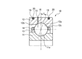
図1に示すように、本実施形態に係る玉軸受10は、高速の工作機械主軸用に適用され、外周面に円弧状の内輪軌道溝11aを有する内輪11と、内周面に円弧状の外輪軌道溝12aを有する外輪12と、保持器14に保持され、所定の接触角αをもって内輪軌道溝11aと外輪軌道溝12aとの間に転動自在に配置された複数の玉13と、を備える。外輪12の軸方向一方側の内周面には、軸方向端面から外輪軌道溝12aまで徐々に縮径する傾斜部を備えたカウンターボア12bが設けられている一方、軸方向他方側の内周面には、溝肩12cが形成されている。
なお、高速の工作機械主軸で使用される用途では、接触角αは、15~30°に設定されている。また、軸受回転時の遠心力による回転側リングの膨張や内外輪温度差による内部ラジアル隙間減少の悪影響を抑制するため、接触角αは、18°<α≦25°に設定されることがより好ましい。
図1に示すように、本実施形態に係る玉軸受10は、高速の工作機械主軸用に適用され、外周面に円弧状の内輪軌道溝11aを有する内輪11と、内周面に円弧状の外輪軌道溝12aを有する外輪12と、保持器14に保持され、所定の接触角αをもって内輪軌道溝11aと外輪軌道溝12aとの間に転動自在に配置された複数の玉13と、を備える。外輪12の軸方向一方側の内周面には、軸方向端面から外輪軌道溝12aまで徐々に縮径する傾斜部を備えたカウンターボア12bが設けられている一方、軸方向他方側の内周面には、溝肩12cが形成されている。
なお、高速の工作機械主軸で使用される用途では、接触角αは、15~30°に設定されている。また、軸受回転時の遠心力による回転側リングの膨張や内外輪温度差による内部ラジアル隙間減少の悪影響を抑制するため、接触角αは、18°<α≦25°に設定されることがより好ましい。
この玉軸受10は、外輪給油型軸受であり、外輪12は、その外周面から内周面まで径方向に亘って貫通する径方向孔15を有する。また、外輪12の外周面には、径方向孔15と連通する凹状溝16が周方向に沿って形成される。これにより、アンギュラ玉軸受10では、図示しないハウジングの給油路から供給された油粒及び潤滑エアが、外輪12の凹状溝16及び径方向孔15を介して、直接、玉13に供給され、オイルエア潤滑が行われる。
なお、周状の凹状溝は、外輪12に設ける代わりに、ハウジングの内周面において、径方向孔15と連通する給油路開口の位置に形成されてもよい。
なお、周状の凹状溝は、外輪12に設ける代わりに、ハウジングの内周面において、径方向孔15と連通する給油路開口の位置に形成されてもよい。
また、本実施形態では、径方向孔15の中心線Xの軸方向位置は、以下のように設定される。
ここで、図1中、自転軸sとは、軸受回転中に、玉13が外輪軌道溝12aや内輪軌道溝11a上を転がり運動する際の回転軸であり、接触角αを表す直線に対してほぼ90°の角度を有する。また、Nで表されている点は、玉13の自転運動の極となる点である。さらに、図中の点A、点Bはそれぞれ、玉13の自転軸sとなす角度λが60°、30°の直線と玉13の表面との交点である。この角度λは、玉13の自転軸sに対して、径方向孔15の中心線Xと玉13の表面との交点から玉13の中心までを結んだ直線がなす時計方向の角度を、正の角度として定義したものであり、自転軸sと該直線との劣角である。なお、本明細書では、径方向孔15の中心線Xとは、その延長線を含むものとする。
ここで、図1中、自転軸sとは、軸受回転中に、玉13が外輪軌道溝12aや内輪軌道溝11a上を転がり運動する際の回転軸であり、接触角αを表す直線に対してほぼ90°の角度を有する。また、Nで表されている点は、玉13の自転運動の極となる点である。さらに、図中の点A、点Bはそれぞれ、玉13の自転軸sとなす角度λが60°、30°の直線と玉13の表面との交点である。この角度λは、玉13の自転軸sに対して、径方向孔15の中心線Xと玉13の表面との交点から玉13の中心までを結んだ直線がなす時計方向の角度を、正の角度として定義したものであり、自転軸sと該直線との劣角である。なお、本明細書では、径方向孔15の中心線Xとは、その延長線を含むものとする。
即ち、本実施形態では、径方向孔15の中心線Xの軸方向位置は、0°<λ≦60°(図1中、T1で表される範囲)、より好ましくは30°≦λ≦60°(図1中、T2で表される範囲)となるように設定される。
つまり、径方向孔15の中心線Xの軌道溝側開口部の軸方向位置は、λが0°を越える、即ち、径方向孔15の中心線Xの軸方向位置を図1の点Nよりも外輪溝底側に設定することによって、潤滑油を給油した際に玉13の表面に付着した潤滑油が、玉13の公転による遠心力および玉13の自転による遠心力によって、外輪軌道溝12a内や内輪軌道溝11a内に運ばれる。特に、軸受回転中の玉13の自転による遠心力と、潤滑油の玉13の表面への付着力によって、玉13の表面の、図1の点Nよりも溝底側に付着した潤滑油が、赤道側(図1中の接触角αを表す直線側)、すなわち、外輪軌道溝12a内や内輪軌道溝11a内に運ばれていく。
つまり、径方向孔15の中心線Xの軌道溝側開口部の軸方向位置は、λが0°を越える、即ち、径方向孔15の中心線Xの軸方向位置を図1の点Nよりも外輪溝底側に設定することによって、潤滑油を給油した際に玉13の表面に付着した潤滑油が、玉13の公転による遠心力および玉13の自転による遠心力によって、外輪軌道溝12a内や内輪軌道溝11a内に運ばれる。特に、軸受回転中の玉13の自転による遠心力と、潤滑油の玉13の表面への付着力によって、玉13の表面の、図1の点Nよりも溝底側に付着した潤滑油が、赤道側(図1中の接触角αを表す直線側)、すなわち、外輪軌道溝12a内や内輪軌道溝11a内に運ばれていく。
図2は、玉13の表面における潤滑油付着性の考え方の模式図を示す。図2(b)の点C、図2(c)の点Dは、それぞれ、玉13の表面における点Nよりも反溝底側、溝底側のある任意の点を表す。また、L1、L2、L3はそれぞれ、玉13の表面を表す円における、点N、点C、点Dを通る接線である。接線L1、L2、L3と径方向(径方向断面と平行)に延びる直線(外輪12に設けた径方向孔15の中心線Xに相当)とがなす角度をそれぞれ、θ1、θ2、θ3とする。
径方向孔15の中心線Xが点Nを越えて反溝底側へ行くと、図2(b)中のθの値が大きくなり、θの値が小さい場合に比べて、潤滑油の玉13への付着性が低下する。つまり、θが大きくなる程、供給された潤滑油が玉13の表面をかするように接触してしまい、周囲に発散してしまう。さらに、潤滑油が保持器14などの玉13以外のところに付着する可能性も高まるため、径方向孔15から供給した潤滑油が、玉13と、内輪11や外輪12との接触部に運ばれにくくなるため、潤滑の信頼性が低下する懸念がある。また、径方向孔15の中心線Xが点Nと交わる位置に径方向孔15を設けた場合、径方向孔15から供給した潤滑油が点Nに付着し、上述の玉13の自転に伴い発生する遠心力による潤滑油運搬効果が小さくなってしまい、潤滑性の低下へつながる懸念がある。したがって、外輪12に設けられた径方向孔15の中心線Xが図1および図2の点Nよりも溝底側にくるように径方向孔15を設けることによって、より安定した潤滑性や回転性能を得ることができる。
一方、径方向孔15の中心線Xが図1のλ>60°の範囲にくると、もしくは溝底を越えて接触角側へくると、玉13と外輪12との接触部に近い領域に潤滑油が供給されることになる。玉13と内外輪11,12との接触部や接触部近傍に、潤滑油が、通常のオイルミスト潤滑による供給量程度でも一気に供給されると、その潤滑油と玉13との間の抵抗が大きくなり、大きな発熱を引き起こす可能性がある。この発熱大により、玉13と外輪12との接触部および接触部近傍の軸受部品および潤滑油温度が上昇し、潤滑油の油膜形成性能が低下することによって、焼付きなどの損傷が発生する懸念がある。
この課題発生を抑制するためには、玉13と内外輪11,12との接触部および接触部近傍に微量の潤滑油を少しずつ供給することが望ましく、図1の0°<λ≦60°、より好ましくは30°≦λ≦60°の範囲に、径方向孔15の中心線Xがくるように径方向孔15を設けることで、上述の玉13の自転に伴い発生する遠心力による潤滑油運搬効果によって、それを達成することができる。30°≦λ≦60°の範囲がより好ましい理由としては、点Nやその近傍(0°<λ<30°)では、玉13の表面の周速が小さく、上述の潤滑油運搬効果も小さくなることが挙げられる。λを30°(図1のB点)以上とすることで、潤滑油が付着する部分、すなわち自転軸sにおける回転半径が玉径の1/2以上となり、適切な潤滑油運搬効果が得られる。より大きな潤滑油運搬効果を得るためには、30°≦λ≦60°範囲に径方向孔15の中心線Xがくることが望ましい。
また、径方向孔15の中心線Xが図1のλ>60°の範囲に来てしまうと、0°<λ≦60°内の場合と比較して、供給された潤滑油が付着する玉13の表面の自転周速度が大きくなりすぎてしまう。自転周速度が大きい部分に潤滑油が供給されてしまうと、自転周速度が小さい部分に供給される場合と比較すると、潤滑油が玉13の表面に付着した際の、玉13と潤滑油の間の抵抗が大きくなってしまう。そのため、λ>60°の範囲に潤滑油が供給されてしまうと、0°<λ≦60°内に潤滑油が供給された場合と比較して、軸受発熱が大きくなってしまう。したがって、径方向孔15の中心線Xが図1の0°<λ≦60°内、より好ましくは30°≦λ≦60°内にくるように径方向孔15を設けることで、より安定した回転性能を得ることができる。
特に、高速の工作機械主軸で使用される軸受(接触角α=15~30°)の軸受は接触角が小さく、玉13と外輪12との接触部が外輪溝底に近くなってしまうので、接触角30°を上限として設定しつつ、上述のλ>60°の範囲に油穴の中心線Xがくると、径方向孔15と、外輪12と玉13間の接触楕円がオーバーラップし、径方向孔15の淵部近傍と玉13との間の接触面圧大を引き起こす可能性がある。したがって、本実施形態の玉軸受10が主に使用される高速用途においては、0°<λ≦60°内、より好ましくは30°≦λ≦60°内に径方向孔15の中心線Xがくるように、径方向孔15を設けることで、より安定した回転性能を得ることができる。
なお、本実施形態では、接触角αが15~30°に設定されているので、径方向孔15の中心線Xの軌道溝側開口部の軸方向位置は、外輪溝底よりも反接触角側(カウンタボア側)の範囲内に形成される。
なお、本実施形態では、接触角αが15~30°に設定されているので、径方向孔15の中心線Xの軌道溝側開口部の軸方向位置は、外輪溝底よりも反接触角側(カウンタボア側)の範囲内に形成される。
なお、接触角αが30°以下に設定される理由は以下の通りである。
本実施形態のようにオイルエア潤滑などが採用される高速の工作機械用主軸用途などでは、接触角αとして30°を超えるような設定がなされると、内外輪11,12の回転軸と玉13の自転軸との乖離が大きくなり、玉13と内輪軌道溝11a及び玉13と外輪軌道溝12aの各接触部のスピン滑り、ジャイロ滑りなどの滑りが顕著になるとともに、玉13の公転による遠心力も非常に大きくなる。
このため、軸受の内部荷重(=軸受運転中の予圧荷重)が増加し、上記接触部の面圧も増大する。その結果、軸受の高速回転時における焼付限界の主因となる指標である限界PV値を超えてしまう。
従って、本用途においては、接触角αを30°以下とすることで、上述のような不具合を回避することが出来る。
本実施形態のようにオイルエア潤滑などが採用される高速の工作機械用主軸用途などでは、接触角αとして30°を超えるような設定がなされると、内外輪11,12の回転軸と玉13の自転軸との乖離が大きくなり、玉13と内輪軌道溝11a及び玉13と外輪軌道溝12aの各接触部のスピン滑り、ジャイロ滑りなどの滑りが顕著になるとともに、玉13の公転による遠心力も非常に大きくなる。
このため、軸受の内部荷重(=軸受運転中の予圧荷重)が増加し、上記接触部の面圧も増大する。その結果、軸受の高速回転時における焼付限界の主因となる指標である限界PV値を超えてしまう。
従って、本用途においては、接触角αを30°以下とすることで、上述のような不具合を回避することが出来る。
ここで、表1に示す、高速の工作機械主軸で要求される主軸運転条件において、接触角の異なる複数の仕様の軸受について解析を行った。その結果を表2に示す。


主軸運転条件は、dmn値(dmn値は、転動体のピッチ円直径(mm)と軸受の回転数(min-1)との積)が130万以上(最近の高速主軸の標準的な使用条件)であり、回転による遠心力が非常に高く、加えて、上述のように接触角が大きくなるにつれて軸受の内部滑り(スピン滑り・ジャイロ滑りなど)が大きくなる。
したがって、高速回転時における運転中の内部予圧を下げ、かつ、転がり接触部のPV値を下げるためには、接触角を大きく設定するに従い、軸受の主軸組込み後の予圧荷重(静止時=回転数0の状態)をより小さくする必要がある(表中(1))。
したがって、高速回転時における運転中の内部予圧を下げ、かつ、転がり接触部のPV値を下げるためには、接触角を大きく設定するに従い、軸受の主軸組込み後の予圧荷重(静止時=回転数0の状態)をより小さくする必要がある(表中(1))。
つまり、仕様検討の結果、表2に示すように、接触角が30°以下では、主軸組込後予圧荷重を付加しても主軸としての機能は満足できる設定となるが、接触角が30°を越えると、予圧荷重を付加することはできず、主軸組込後、内部すきまが0よりプラスすきま(いわゆるガタの状態)の設定とならざるを得ない。したがって、運転中の主軸の剛性が確保できず、振動が発生し易くなると共に、工作機械主軸の場合、回転精度も悪化し加工精度不良が生じる。
また、予圧が与えられていない軸受の状態にあっては、軸受にガタがあるため、主軸の急加速運転や急減速運転時に、転がり接触部における公転滑り(スキッディング;回転輪から転動体に駆動力が伝達されず、両者間の接触部で極めて大きな滑りが生じる現象)が発生しやすくなり、本現象による異常昇温から摩耗や焼付きに至る可能性がある。
以上の試算結果からもわかるように、軸受の接触角は30°以下とならざるを得ず、本条件下とした場合、0°<λ≦60°の効果が有効に発揮できる。
以上の試算結果からもわかるように、軸受の接触角は30°以下とならざるを得ず、本条件下とした場合、0°<λ≦60°の効果が有効に発揮できる。
図3は、本実施形態の径方向孔15の中心線Xの軸方向位置が、0°<λ≦60°の範囲となるように設定される例を示しており、図3(a)は、λ=1°のとき、図3(b)は、λ=31°のとき、図3(c)は、λ=60°のとき、のそれぞれの径方向孔15を示している。
図3(a)は、径方向孔15の外輪内径側開口部全てが、カウンターボア12bに位置し、外輪軌道溝12aの外側にあるため、軌道溝加工時に油孔開口部に配慮する必要が無く(油孔開口部と軌道溝との交差部のバリなど)、加工性が良い。さらには、玉13と油孔開口部との接触、または、玉13と外輪軌道溝12aとの接触楕円と油孔開口部が重なることがないため、組立作業性や取扱性が良い。
即ち、油孔開口部が外輪軌道溝12aの外側にあるため、玉表面にキズが入る可能性や、その玉表面のキズによって、軸受の音響性能低下や早期損傷などが発生する可能性がない。
即ち、油孔開口部が外輪軌道溝12aの外側にあるため、玉表面にキズが入る可能性や、その玉表面のキズによって、軸受の音響性能低下や早期損傷などが発生する可能性がない。
図3(b)は、径方向孔15の外輪内径側開口部が、カウンターボア12bと軌道溝12a内に跨って形成されている。通常の組立作業や軸受使用方法では、玉13と外輪軌道溝12a内のカウンターボア近傍部は接触することが無いため、上記と同様の理由で、組立作業性や取扱性が良い。また、油孔開口部の一部が軌道溝12a内にあり、玉13と内・外輪11、12との接触部に近いため、油の供給性が良い。
図3(c)は、径方向孔15の外輪内径側開口部全てが、外輪軌道溝12a内にあり、かつ軌道溝内のカウンターボア側(溝底に対して接触角と反対側)にある。そのため、軸受回転時に油孔開口部と玉13と外輪軌道溝12aとの接触楕円がオーバーラップすることはなく、オーバーラップすることによって発生する接触面圧過大などが発生せず、軸受の早期損傷などが発生する可能性は低い。また、油の供給性もよく、軸受の良好な回転性能を実現することができる。
なお、図3(c)のように、油孔開口部が外輪軌道溝12a内にある場合には、軸受組立時や軸受を主軸に組み込む際の作業方法を留意することで、上述した、油孔開口部と軌道溝との交差部のバリや、玉表面にキズが入る可能性が解消できる。
なお、図3(c)のように、油孔開口部が外輪軌道溝12a内にある場合には、軸受組立時や軸受を主軸に組み込む際の作業方法を留意することで、上述した、油孔開口部と軌道溝との交差部のバリや、玉表面にキズが入る可能性が解消できる。
なお、本実施形態では、径方向孔15の直径は、潤滑油の供給性を考慮して、0.5~1.5mmに設定されている。また、本実施形態では、径方向孔15は、径方向に亘って一様な直径を有している。
したがって、本実施形態の玉軸受10によれば、外輪12の径方向孔15の中心線Xの軸方向位置は、玉13の自転軸sに対して、径方向孔15の中心線Xと玉13の表面との交点から玉13の中心Oまでを結んだ直線がなす劣角をλとしたとき、0°<λ≦60°となるように設定されるので、高速用途で使用される玉軸受において、より安定した潤滑性や回転性能を得ることができる。
また、本実施形態では、図4に示す変形例のように、玉軸受10の外輪12の外周面において、凹状溝16を挟む軸方向両側に、環状溝19を周方向に沿って形成し、各環状溝19に、例えばO-リングなどの環状の弾性部材である、シール部材20を配置してもよい。これにより、潤滑油供給時に、外輪12の外周面と外輪12が内嵌するハウジングの内周面との間で発生する可能性のある潤滑油漏れを防止することができる。
(第2実施形態)
次に、本発明の第2実施形態に係る玉軸受について、図5~図7を参照して詳細に説明する。なお、第1実施形態と同一または同等部分については、同一符号を付して説明を省略或いは簡略化する。
次に、本発明の第2実施形態に係る玉軸受について、図5~図7を参照して詳細に説明する。なお、第1実施形態と同一または同等部分については、同一符号を付して説明を省略或いは簡略化する。
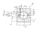
本実施形態のアンギュラ玉軸受10aは、外輪12の内周面のカウンターボア側の形状において、第1実施形態のものと異なる。即ち、本実施形態では、カウンターボア12bは、軸方向端面から軌道溝12a側に向かって徐々に縮径する傾斜部(円錐面)12b1と、傾斜部12b1と軌道溝12aまでを結ぶ、玉軸受の回転軸中心線L(図10参照)と平行なストレート部(円筒面)12b2と、を有している。
アンギュラ玉軸受10aは、組込後に軸受が分解するのを防ぐために、外輪12または内輪11に、図5に示すかかり代Δrという部分を設けている。そのため、アンギュラ玉軸受10aを組み立てる際は、外輪12を加熱し、かかり代Δrの分だけ外輪12を膨張させて組立てを行う。この組立時の外輪加熱温度や時間を一定にし、組立製造ラインの管理をしやすくするため、また、組立て後の軸受分解を防止するために、このかかり代Δrの寸法は、最終仕上研削加工により、数十μmオーダーで管理することが望ましい。
このように、かかり代Δrを規定するストレート部12b2を設ける本実施形態の場合、カウンターボア12bが傾斜部のみからなり、カウンターボア12bと外輪軌道溝12aとの間にエッジが設けられる場合と比べて、かかり代Δrの寸法管理の容易化(研削加工時、寸法精度が得やすく、かつ、ストレート部が存在するので、かかり代径寸法Dが測定しやすい)や軸受組立時の玉キズ発生の抑制が可能となる。
この実施形態においても、外輪12の径方向孔15の中心線Xの軸方向位置は、玉13の自転軸sに対して、径方向孔15の中心線Xと玉13の表面との交点Nから玉13の中心Oまでを結んだ直線がなす劣角をλとしたとき、0°<λ≦60°、好ましくは30°≦λ≦60°となるように設定されればよい。これにより、高速用途で使用される玉軸受において、より安定した潤滑性や回転性能を得ることができる。
具体的には、本実施形態では、径方向孔15の中心線Xの軸方向位置は、図6(a)~図7(b)に示すいずれかの位置に設計されればよい。
具体的には、本実施形態では、径方向孔15の中心線Xの軸方向位置は、図6(a)~図7(b)に示すいずれかの位置に設計されればよい。
図6(a)は、径方向孔15の外輪内径側開口部全てが、カウンターボア12bの傾斜部12b1内に位置している。
このような位置に径方向孔15を設けることで、軌道溝加工時に油孔開口部のバリ等を考慮しなくてよく、外輪軌道溝12aの加工性が良い。また、軸受を主軸へ組み込む際や使用時に、玉13と外輪軌道溝12aとの接触楕円と油孔開口部がオーバーラップすることがないため、玉キズの発生や、接触面圧の異常な増大を抑制することができる。
図6(b)は、径方向孔15の外輪内径側開口部が、傾斜部12b1とストレート部12b2に跨るように位置している。これにより、図6(a)の玉軸受の効果に加えて、より軸受内部側へ油を供給できるため、軸受のより良い回転性能が得られる。
図6(c)は、径方向孔15の外輪内径側開口部全てが、ストレート部12b2に位置している。これにより、図6(a)及び(b)の玉軸受の効果に加えて、開口部の一部が傾斜していないので、供給した油の直進性が確保でき、より確実に油を供給できる。
詳しくは、図6(a)及び(b)の玉軸受では、径方向孔15の外輪内径側開口部がカウンターボアの傾斜部12b1に沿って形成され、油の供給方向(玉軸受の回転軸中心線Lと直交する方向)に対して、開口部の径方向から見た断面が傾いている。このような場合、開口部の軸方向端面側の方がストレート部側よりも空間が広いため、軸方向端面側での圧力が弱まり、カウンターボアの傾斜部側に油と共に供給されるエアが流れ、それに伴い、油も傾斜部側へ流れてしまう可能性がある。これに対し、図6(c)に示す玉軸受では、径方向孔15の外輪内径側開口部全てをストレート部12b2に設けることで、開口部の径方向から見た断面が油の供給方向に対して平行であるため、上述した油の直進性が確保できる。
図7(a)は、径方向孔15の外輪内径側開口部が、ストレート部12b2と外輪軌道溝12aに跨るように位置する。このような径方向孔15を設けることによって、径方向孔15の開口部の一部が外輪軌道溝12aとオーバーラップしているため、油の供給性が向上する。
図7(b)は、径方向孔15の外輪内径側開口部全てが、外輪軌道溝12aに位置する。このように径方向孔15を設けることによって、玉13と外輪軌道溝12aとの間の狭いすきまに油が直接供給される。そのため、特に潤滑油量がより多く必要とされる高速運転時の油膜切れを抑制することができるため、安定した高速性を得ることができる。
尚、本発明は、前述した実施形態に限定されるものではなく、適宜、変形、改良、等が可能である。
例えば、径方向孔は、外輪の外周面から内周面まで径方向に亘って貫通するものであればよく、本実施形態の半径方向(径方向断平面と平行)に沿って形成されるもの以外に、周方向に傾斜させても構わない。
また、上記実施形態では、外輪12は、1本の径方向孔を有するとしているが、これに限らず、複数本の径方向孔を有してもよい。
なお、外輪の径方向孔への潤滑油の補給方法は、オイルエア潤滑以外にオイルミスト潤滑を採用してもよい。場合によってはオイルジェット潤滑も可能である。しかしながら、グリースを軸受の周辺部や主軸外部の潤滑剤補給装置を用いて外輪12の径方向孔15から給脂するグリース補給法の場合、径方向孔15が外輪軌道溝12a内、カウンターボア12bと外輪軌道溝12aとの交点部、或いは、カウンターボア12b内の外輪軌道溝近傍側に開口するように形成されると、増ちょう剤が含まれる半固体であるグリースが外輪軌道溝12a内に供給されてしまう。
この場合、グリースが外輪軌道溝12a内に噛み込まれるので、攪拌抵抗により、トルクの増大や異常発熱等の問題が生じる。特に、これらの問題は、本実施形態のような高速回転において生じ易い。従って、増ちょう剤を含まない潤滑油を供給する油潤滑方法が本発明において望ましい。
この場合、グリースが外輪軌道溝12a内に噛み込まれるので、攪拌抵抗により、トルクの増大や異常発熱等の問題が生じる。特に、これらの問題は、本実施形態のような高速回転において生じ易い。従って、増ちょう剤を含まない潤滑油を供給する油潤滑方法が本発明において望ましい。
更に、本発明の玉軸受は、工作機械用主軸装置に適用されるものに限定されるものでなく、一般産業機械や、モータなどの高速回転する装置の玉軸受としても適用することができる。
本出願は、2016年7月29日出願の日本特許出願2016-150501に基づくものであり、その内容はここに参照として取り込まれる。
10 アンギュラ玉軸受(玉軸受)
11 内輪
11a 内輪軌道溝
12 外輪
12a 外輪軌道溝
12b カウンターボア
12c 溝肩
13 玉
14 保持器
15 径方向孔
16 凹状溝
11 内輪
11a 内輪軌道溝
12 外輪
12a 外輪軌道溝
12b カウンターボア
12c 溝肩
13 玉
14 保持器
15 径方向孔
16 凹状溝
Claims (14)
- 外周面に内輪軌道溝を有する内輪と、内周面に外輪軌道溝を有する外輪と、前記内輪軌道溝と前記外輪軌道溝との間に転動自在に配置される複数の玉と、を備え、潤滑油によって潤滑される玉軸受であって、
前記外輪は、その外周面から内周面まで径方向に亘って貫通する少なくとも1つの径方向孔を有し、
該径方向孔の中心線の軸方向位置は、前記玉の自転軸に対して、前記径方向孔の中心線と前記玉の表面との交点から前記玉の中心までを結んだ直線がなす劣角をλとしたとき、0°<λ≦60°となるように設定される、玉軸受。 - 前記外輪の内周面は、軸方向端面から前記外輪軌道溝に向かって徐々に縮径する傾斜部と、該傾斜部と前記外輪軌道溝までを結ぶ、前記玉軸受の回転軸中心線と平行なストレート部とを有するカウンターボアを有し、
前記径方向孔の内径側開口部全ては、前記傾斜部内に位置する、請求項1に記載の玉軸受。 - 前記外輪の内周面は、軸方向端面から前記外輪軌道溝に向かって徐々に縮径する傾斜部と、該傾斜部と前記外輪軌道溝までを結ぶ、前記玉軸受の回転軸中心線と平行なストレート部とを有するカウンターボアを有し、
前記径方向孔の内径側開口部は、前記傾斜部と前記ストレート部に跨るように位置する、請求項1に記載の玉軸受。 - 前記外輪の内周面は、軸方向端面から前記外輪軌道溝に向かって徐々に縮径する傾斜部と、該傾斜部と前記外輪軌道溝までを結ぶ、前記玉軸受の回転軸中心線と平行なストレート部とを有するカウンターボアを有し、
前記径方向孔の内径側開口部全ては、前記ストレート部に位置する、請求項1に記載の玉軸受。 - 前記外輪の内周面は、軸方向端面から前記外輪軌道溝に向かって徐々に縮径する傾斜部と、該傾斜部と前記外輪軌道溝までを結ぶ、前記玉軸受の回転軸中心線と平行なストレート部とを有するカウンターボアを有し、
前記径方向孔の内径側開口部は、前記ストレート部と前記外輪軌道溝に跨るように位置する、請求項1に記載の玉軸受。 - 前記外輪の内周面は、軸方向端面から前記外輪軌道溝に向かって徐々に縮径する傾斜部と、該傾斜部と前記外輪軌道溝までを結ぶ、前記玉軸受の回転軸中心線と平行なストレート部とを有するカウンターボアを有し、
前記径方向孔の内径側開口部全ては、前記外輪軌道溝に位置する、請求項1に記載の玉軸受。 - 前記外輪の内周面は、軸方向端面から前記外輪軌道溝まで徐々に縮径する傾斜部を備えたカウンターボアを有し、
前記径方向孔の内径側開口部全てが、前記カウンターボアに位置する、請求項1に記載の玉軸受。 - 前記外輪の内周面は、軸方向端面から前記外輪軌道溝まで徐々に縮径する傾斜部を備えたカウンターボアを有し、
前記径方向孔の内径側開口部は、前記カウンターボアと前記外輪軌道溝に跨るように位置する、請求項1に記載の玉軸受。 - 前記外輪の内周面は、軸方向端面から前記外輪軌道溝まで徐々に縮径する傾斜部を備えたカウンターボアを有し、
前記径方向孔の内径側開口部全てが、前記外輪軌道溝に位置する、請求項1に記載の玉軸受。 - 該径方向孔の中心線の軸方向位置は、30°≦λ≦60°となるように設定される、請求項1~9のいずれか1項に記載の玉軸受。
- 前記外輪の外周面には、前記径方向孔と連通する凹状溝が周方向に沿って形成されている、請求項1~10のいずれか1項に記載の玉軸受。
- 前記外輪の外周面には、上記凹状溝を挟む軸方向両側に環状溝が周方向に沿って形成され、前記各環状溝には、それぞれ環状のシール部材が配置される、請求項11に記載の玉軸受。
- 前記径方向孔の直径が0.5~1.5mmである、請求項1~12のいずれか1項に記載の玉軸受。
- 工作機械主軸用軸受であることを特徴とする請求項1~13のいずれか1項に記載の玉軸受。
Priority Applications (4)
| Application Number | Priority Date | Filing Date | Title |
|---|---|---|---|
| CN201780045980.9A CN109477522A (zh) | 2016-07-29 | 2017-07-26 | 滚珠轴承 |
| EP17834436.2A EP3492760B1 (en) | 2016-07-29 | 2017-07-26 | Ball bearing |
| US16/321,262 US20190178291A1 (en) | 2016-07-29 | 2017-07-26 | Ball bearing |
| KR1020197002553A KR20190022773A (ko) | 2016-07-29 | 2017-07-26 | 볼 베어링 |
Applications Claiming Priority (2)
| Application Number | Priority Date | Filing Date | Title |
|---|---|---|---|
| JP2016-150501 | 2016-07-29 | ||
| JP2016150501A JP2018017382A (ja) | 2016-07-29 | 2016-07-29 | 玉軸受 |
Publications (1)
| Publication Number | Publication Date |
|---|---|
| WO2018021434A1 true WO2018021434A1 (ja) | 2018-02-01 |
Family
ID=61016191
Family Applications (1)
| Application Number | Title | Priority Date | Filing Date |
|---|---|---|---|
| PCT/JP2017/027105 Ceased WO2018021434A1 (ja) | 2016-07-29 | 2017-07-26 | 玉軸受 |
Country Status (7)
| Country | Link |
|---|---|
| US (1) | US20190178291A1 (ja) |
| EP (1) | EP3492760B1 (ja) |
| JP (1) | JP2018017382A (ja) |
| KR (1) | KR20190022773A (ja) |
| CN (1) | CN109477522A (ja) |
| TW (1) | TW201805539A (ja) |
| WO (1) | WO2018021434A1 (ja) |
Families Citing this family (1)
| Publication number | Priority date | Publication date | Assignee | Title |
|---|---|---|---|---|
| KR102878983B1 (ko) * | 2019-10-31 | 2025-10-30 | 에이치엘만도 주식회사 | 스티어 바이 와이어식 조향장치 |
Citations (3)
| Publication number | Priority date | Publication date | Assignee | Title |
|---|---|---|---|---|
| JP2003232366A (ja) * | 2002-02-06 | 2003-08-22 | Nsk Ltd | 転がり軸受及びグリース補給装置 |
| JP2013079711A (ja) * | 2010-10-21 | 2013-05-02 | Ntn Corp | 転がり軸受および転がり軸受装置 |
| JP2016516969A (ja) * | 2013-05-08 | 2016-06-09 | シェフラー テクノロジーズ アー・ゲー ウント コー. カー・ゲーSchaeffler Technologies AG & Co. KG | グリース潤滑式のアンギュラ玉軸受 |
Family Cites Families (10)
| Publication number | Priority date | Publication date | Assignee | Title |
|---|---|---|---|---|
| JPS63180726U (ja) * | 1987-05-14 | 1988-11-22 | ||
| JP2005009643A (ja) * | 2003-06-20 | 2005-01-13 | Nsk Ltd | 非分離型アンギュラ玉軸受 |
| CN1598341A (zh) * | 2003-09-19 | 2005-03-23 | Ntn株式会社 | 滚动轴承用护圈和具有它的滚动轴承 |
| JP4305110B2 (ja) * | 2003-09-26 | 2009-07-29 | 株式会社ジェイテクト | 軸受装置 |
| JP4812367B2 (ja) * | 2005-08-24 | 2011-11-09 | Ntn株式会社 | 空気サイクル冷凍冷却システムおよびその空気サイクル冷凍冷却用タービンユニット |
| DE102005052677A1 (de) * | 2005-11-04 | 2007-05-10 | Schaeffler Kg | Hochgeschwindigkeitslager, insbesondere direktgeschmiertes Spindellager für eine Werkzeugmaschine |
| DE102006011978A1 (de) * | 2006-03-16 | 2007-09-20 | Schaeffler Kg | Hochgeschwindigkeitslager, insbesondere direktgeschmiertes Spindellager für eine Werkzeugmaschine |
| JP2008075738A (ja) * | 2006-09-20 | 2008-04-03 | Mitsubishi Heavy Ind Ltd | 軸受装置 |
| EP2327897B1 (en) * | 2008-09-24 | 2018-07-04 | JTEKT Corporation | Rolling bearing |
| CN102171470B (zh) * | 2009-11-20 | 2015-08-19 | 日本精工株式会社 | 串联角接触球轴承 |
-
2016
- 2016-07-29 JP JP2016150501A patent/JP2018017382A/ja active Pending
-
2017
- 2017-07-26 KR KR1020197002553A patent/KR20190022773A/ko not_active Abandoned
- 2017-07-26 WO PCT/JP2017/027105 patent/WO2018021434A1/ja not_active Ceased
- 2017-07-26 EP EP17834436.2A patent/EP3492760B1/en active Active
- 2017-07-26 US US16/321,262 patent/US20190178291A1/en not_active Abandoned
- 2017-07-26 CN CN201780045980.9A patent/CN109477522A/zh active Pending
- 2017-07-27 TW TW106125346A patent/TW201805539A/zh unknown
Patent Citations (3)
| Publication number | Priority date | Publication date | Assignee | Title |
|---|---|---|---|---|
| JP2003232366A (ja) * | 2002-02-06 | 2003-08-22 | Nsk Ltd | 転がり軸受及びグリース補給装置 |
| JP2013079711A (ja) * | 2010-10-21 | 2013-05-02 | Ntn Corp | 転がり軸受および転がり軸受装置 |
| JP2016516969A (ja) * | 2013-05-08 | 2016-06-09 | シェフラー テクノロジーズ アー・ゲー ウント コー. カー・ゲーSchaeffler Technologies AG & Co. KG | グリース潤滑式のアンギュラ玉軸受 |
Also Published As
| Publication number | Publication date |
|---|---|
| CN109477522A (zh) | 2019-03-15 |
| TW201805539A (zh) | 2018-02-16 |
| EP3492760B1 (en) | 2021-03-24 |
| EP3492760A1 (en) | 2019-06-05 |
| US20190178291A1 (en) | 2019-06-13 |
| JP2018017382A (ja) | 2018-02-01 |
| EP3492760A4 (en) | 2019-07-31 |
| KR20190022773A (ko) | 2019-03-06 |
Similar Documents
| Publication | Publication Date | Title |
|---|---|---|
| WO2018034245A1 (ja) | 軸受装置、及び工作機械用主軸装置 | |
| WO2018034240A1 (ja) | 玉軸受、主軸装置及び工作機械 | |
| EP3495679B1 (en) | Ball bearing and main shaft device for machine tool | |
| WO2018021434A1 (ja) | 玉軸受 | |
| JP6881656B2 (ja) | アンギュラ玉軸受、及び工作機械用主軸装置 | |
| US10197094B2 (en) | Double-row spherical roller bearing | |
| WO2018034246A1 (ja) | 玉軸受、及び工作機械用主軸装置 | |
| TWI760065B (zh) | 角接觸滾珠軸承及工具機用主軸裝置 | |
| TWI704299B (zh) | 滾珠軸承及工具機用主軸裝置 | |
| WO2018181524A1 (ja) | 転がり軸受用保持器および外輪給油孔付き転がり軸受 |
Legal Events
| Date | Code | Title | Description |
|---|---|---|---|
| 121 | Ep: the epo has been informed by wipo that ep was designated in this application |
Ref document number: 17834436 Country of ref document: EP Kind code of ref document: A1 |
|
| ENP | Entry into the national phase |
Ref document number: 20197002553 Country of ref document: KR Kind code of ref document: A |
|
| NENP | Non-entry into the national phase |
Ref country code: DE |
|
| ENP | Entry into the national phase |
Ref document number: 2017834436 Country of ref document: EP Effective date: 20190228 |