WO2018021564A1 - センサケース - Google Patents
センサケース Download PDFInfo
- Publication number
- WO2018021564A1 WO2018021564A1 PCT/JP2017/027554 JP2017027554W WO2018021564A1 WO 2018021564 A1 WO2018021564 A1 WO 2018021564A1 JP 2017027554 W JP2017027554 W JP 2017027554W WO 2018021564 A1 WO2018021564 A1 WO 2018021564A1
- Authority
- WO
- WIPO (PCT)
- Prior art keywords
- sensor case
- tire
- sensor
- lower member
- pedestal
- Prior art date
- Legal status (The legal status is an assumption and is not a legal conclusion. Google has not performed a legal analysis and makes no representation as to the accuracy of the status listed.)
- Ceased
Links
Images


Classifications
-
- H—ELECTRICITY
- H05—ELECTRIC TECHNIQUES NOT OTHERWISE PROVIDED FOR
- H05K—PRINTED CIRCUITS; CASINGS OR CONSTRUCTIONAL DETAILS OF ELECTRIC APPARATUS; MANUFACTURE OF ASSEMBLAGES OF ELECTRICAL COMPONENTS
- H05K5/00—Casings, cabinets or drawers for electric apparatus
- H05K5/02—Details
- H05K5/0217—Mechanical details of casings
-
- B—PERFORMING OPERATIONS; TRANSPORTING
- B60—VEHICLES IN GENERAL
- B60C—VEHICLE TYRES; TYRE INFLATION; TYRE CHANGING; CONNECTING VALVES TO INFLATABLE ELASTIC BODIES IN GENERAL; DEVICES OR ARRANGEMENTS RELATED TO TYRES
- B60C19/00—Tyre parts or constructions not otherwise provided for
-
- B—PERFORMING OPERATIONS; TRANSPORTING
- B60—VEHICLES IN GENERAL
- B60C—VEHICLE TYRES; TYRE INFLATION; TYRE CHANGING; CONNECTING VALVES TO INFLATABLE ELASTIC BODIES IN GENERAL; DEVICES OR ARRANGEMENTS RELATED TO TYRES
- B60C23/00—Devices for measuring, signalling, controlling, or distributing tyre pressure or temperature, specially adapted for mounting on vehicles; Arrangement of tyre inflating devices on vehicles, e.g. of pumps or of tanks; Tyre cooling arrangements
- B60C23/02—Signalling devices actuated by tyre pressure
- B60C23/04—Signalling devices actuated by tyre pressure mounted on the wheel or tyre
-
- B—PERFORMING OPERATIONS; TRANSPORTING
- B60—VEHICLES IN GENERAL
- B60C—VEHICLE TYRES; TYRE INFLATION; TYRE CHANGING; CONNECTING VALVES TO INFLATABLE ELASTIC BODIES IN GENERAL; DEVICES OR ARRANGEMENTS RELATED TO TYRES
- B60C23/00—Devices for measuring, signalling, controlling, or distributing tyre pressure or temperature, specially adapted for mounting on vehicles; Arrangement of tyre inflating devices on vehicles, e.g. of pumps or of tanks; Tyre cooling arrangements
- B60C23/02—Signalling devices actuated by tyre pressure
- B60C23/04—Signalling devices actuated by tyre pressure mounted on the wheel or tyre
- B60C23/0491—Constructional details of means for attaching the control device
- B60C23/0493—Constructional details of means for attaching the control device for attachment on the tyre
Definitions
- the present invention relates to a sensor case in which a sensor for acquiring tire information is housed.
- a sensor case containing a sensor module in which a sensor such as a pressure sensor, a temperature sensor, an acceleration sensor, a battery or a power generation element, and a radio is integrated is attached to the inner surface of a tire via a rubber base.
- a technique is known that detects the state of a running tire, such as the tire internal pressure, and transmits detected sensor information to the vehicle (see, for example, Patent Document 1).
- the tire inner surface is repeatedly distorted during running, so the adhesive layer between the pedestal and the tire inner surface cracks, and the sensor case and the pedestal fall off from the tire inner surface, or the pedestal storage part and bottom surface There may be a crack between the sensor case and the sensor case.
- FIG. 8 when the sensor case 50 comes off the pedestal 20 and collides with the inner surface of the tire 30 or rolls on the inner surface of the tire 30, the corner portion 50 ⁇ / b> K of the sensor case 50 comes into contact with the inner surface of the tire 30.
- the ridge 31R of the inner liner 31 that is the inner surface of the tire 30 is scraped, or as shown in FIG. There was a problem that the inner surface of the tire 30 was damaged.
- the present invention has been made in view of the conventional problems, and an object of the present invention is to provide a sensor case having a shape that does not damage the tire inner surface even if the tire inner surface rolls off the tire inner surface or pedestal.
- the present invention is a sensor case in which a sensor for acquiring tire information is housed, and has a bottom surface attached to an inner surface of the tire or a base for mounting the sensor case on the inner surface of the tire.
- a lower member, and an upper member projecting from the surface opposite to the bottom surface of the lower member opposite to the bottom surface, the width of the upper member being smaller than the width of the lower member, and the side surface of the lower member Is formed from a curved surface that protrudes outward in the width direction, and a side surface of the upper member and a top surface that is the surface opposite to the bottom surface of the upper member are connected by a curved surface that is in contact with the top surface.
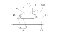
- FIG. 1 is a view showing a sensor case 10 according to the present invention
- FIG. 2 is a cross-sectional view of a sensor case attached to a rubber pedestal 20 (hereinafter referred to as a sensor case 10G with a rubber pedestal).
- the sensor case 10 includes a storage portion 11 stored in the rubber pedestal 20, a grip portion 12 formed so as to protrude from the storage portion 11, and a sensor module 13.
- the sensor module 13 is an integrated sensor 14 for measuring temperature, pressure, vibration and the like in the tire, a power generation element 15 as a power source, and a radio 16 for transmitting data detected by the sensor 14.
- it is built in at least one of the storage portion 11 and the grip portion 12.
- the protruding direction of the gripping part 12 is referred to as the upper side
- the direction opposite to the protruding direction of the gripping part 12 is referred to as the lower side
- the lower side is the inner surface (here, the inner liner 31) side of the tire 30 when the sensor case 10G with the rubber pedestal is mounted.
- the sensor case 10 of this example is formed so that the maximum width of the storage portion 11 is larger than the width of the grip portion 12. That is, the storage portion 11 corresponds to the lower member of the present invention, and the grip portion 12 corresponds to the upper member.
- the upper surface of the storage portion 11 is referred to as an upper surface 11a
- the lower surface is referred to as a bottom surface 11b
- the upper surface of the grip portion 12 is referred to as a top surface 12a
- the lower surface of the grip portion 12 is referred to as a connection surface 12b.
- the storage portion 11 that is a lower member is constituted by a rotating body that is obtained by rotating half of a rounded rectangle (track-shaped figure) around a central axis J. Therefore, the upper surface 11a and the bottom surface 11b of the storage part 11 are flat surfaces, and the side surface 11c is a curved surface that protrudes outward in the width direction when the shape when cut by a plane passing through the central axis J is a semicircle.
- the side surface 11c and the upper surface 11a of the storage part 11 are connected by a curved surface 11p in contact with the upper surface 11a, and the side surface 11c and the bottom surface 11b are connected by a curved surface 11q in contact with the bottom surface 11b.
- the maximum width part of the side surface 11c is formed from the curved surface 11r convex to the width direction outer side.
- the gripping portion 12 that is the upper member the upper left part of the rectangular figure is constituted by a rotating body obtained by rotating a figure having an arc shape with a circumferential angle of 90 ° about the central axis J. Therefore, the top surface 12a and the connection surface 12b of the grip portion 12 are flat, and the cylindrical side surface 12c and the top surface 12a are curved surfaces that are in contact with the top surface 12a. It is rotated around and connected by a curved surface.
- the rubber pedestal 20 is a rubber member having an opening 21 for inserting the storage portion 11 of the sensor case 10 and a storage recess 22 for storing the storage portion 11 of the sensor case 10, and an inner liner 31 of the tire 30. And a side wall portion 24 connecting the bottom portion 23 and the opening 21.
- the side wall portion 24 is a cylindrical member having a concave portion having a rotating body shape whose cross-sectional shape when cut along a plane parallel to the central axis J is a rounded rectangular shape, and its outer peripheral surface approaches the bottom portion 23 side. , So as to be away from the central axis J.
- a housing recess 22 having the same shape as the housing portion 11 of the sensor case 10 is formed by the inner wall surface of the side wall portion 24 and the inner wall surface of the bottom portion 23.
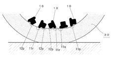
- the sensor case 10 of the present invention Since the sensor case 10 of the present invention has the above-described shape, the sensor case 10 is detached from the pedestal 20 due to, for example, a crack between the bottom 23 and the side wall 24 of the pedestal 20, and the inner surface of the tire 30. 3, since the portions (11p, 11q, 11r, 12p) of the sensor case 10 that contact the surface of the inner liner 31 that is the inner surface of the tire 30 are all curved surfaces, as shown in FIG. The rubbing trace is not made on the inner surface of the tire 30 and the inner surface of the tire 30 is not scraped. That is, if the sensor case 10 of the present invention is used, the inner surface of the tire 30 can be prevented from being damaged even if the sensor case 10 comes off the pedestal and rolls on the inner surface of the tire.
- the gripping portion 12 exposed from the pedestal 20 has the cylindrical side surface 12c and the top surface 12a in contact with the top surface 12a. Since it is connected by the curved surface 12p, the inner surface of the tire 30 is not damaged.
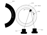
- Example 4 As shown in FIG. 4, the pedestal 20 into which the sensor case 10 according to the present invention is inserted is fixed to the tire inner surface with an adhesive, and then the tire 30 is pressed against the drum 40 while the tire 30 is pressed at a speed of 60 km / h. A drum test for rotating 30 was performed, and the surface state of the inner liner after traveling 5000 [km] was examined. The tire size was 195 / 65R15, and the test was performed with an internal pressure of 230 [kPa] and a load of 615 [kg]. A sensor case 10 according to the present invention is shown in FIG. For comparison, a similar test was performed on the sensor case 50 in which the grip portion 12 is cylindrical (comparative example).
- the weight of the sensor case was 20 g, and the test was performed in a state where the sensor cases 10 and 50 were easily detached from the pedestal 20 by, for example, halving the height of the side wall portion 24 of the pedestal 20.
- the sensor cases 10 and 50 may be easily detached from the pedestal 20 by making a cut in advance between the bottom 23 and the side wall 24 of the pedestal 20.
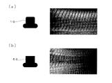
- the test results are shown in FIGS. 5 (a) and 5 (b).
- (A) is a test result of the sensor case 10 according to the present invention
- (b) is a test result of the sensor case 50 in which the grip portion 12 is cylindrical.
- FIG. 1 is a test result of the sensor case 10 according to the present invention
- the inner liner surface is not scraped or rubbed, whereas in the comparative example shown in FIG. 5 (b), the ridge portion of the inner liner rotates. Not only was it shaved in the direction, but there were also traces of rubbing even in areas where it was not shaved. Thus, it was confirmed that if the portion of the sensor case that contacts the tire inner surface is a curved surface, the tire inner surface can be prevented from being damaged even if the sensor case is detached from the base and rolls on the tire inner surface.
- the case where the sensor case 10 is mounted on the pedestal 20 has been described.
- the sensor case 10 is an embodiment of the present invention, the sensor Needless to say, even when the case 10 comes off the tire inner surface and rolls on the tire inner surface, the tire inner surface is not damaged.
- the side surface 12c and the top surface 12a of the grip portion 12 are in contact with the side surface 12c and the top surface 12a, and the circular arc shape has a circumferential angle of 90 °. As shown in FIG.
- the slope of the tangent A at the connection point with the top surface 12a of the curved surface 12p and the connection with the curved surface 12p of the top surface 12a are connected.
- the inclination of the tangent line B at the point does not have to be completely coincident, and the angle ⁇ formed by the two tangent lines A and B may be in the range of 0 ° to 15 °.
- the holding part 12 which is an upper member was made into the column shape, and the column-shaped side surface 12c and the top surface 12a were connected by the curved surface, as shown to FIG. 7 (a), (b).
- the sensor case 10 can be further downsized. As shown in FIGS. 7C and 7D, if the upper member is 2/3 or more of a sphere or a spheroid, the sensor case can be more easily gripped.
- the present invention is a sensor case in which a sensor for acquiring tire information is housed, and is a bottom surface attached to an inner surface of the tire or a pedestal for mounting the sensor case on the inner surface of the tire.
- the side surface of the upper member is formed from a curved surface that protrudes outward in the width direction, and the side surface of the upper member and the top surface that is the surface opposite to the bottom surface of the upper member are connected by a curved surface that contacts the top surface.
- the portion that contacts the tire inner surface is a curved surface, so that the tire inner surface can be prevented from being damaged. Further, even when the sensor case is removed from the tire inner surface together with the pedestal and rolled on the tire inner surface, the tire inner surface is not damaged for the same reason as described above.
- the side surface of the lower member and the bottom surface are connected by a curved surface in contact with the bottom surface, and the side surface of the lower member and the upper surface that is a surface opposite to the bottom surface side of the lower member, Since the connection is made with the curved surface in contact with the upper surface, it is possible to prevent the tire inner surface from being damaged even when the sensor case collides with the tire inner surface. Further, since the upper member is a part of a sphere or a part of a spheroid, the sensor case can be miniaturized. If the upper member is 2/3 or more of a sphere or a spheroid, the sensor case can be more easily gripped.
- 10 sensor case 20 rubber pedestal, 10G sensor case with rubber pedestal, 11 storage section, 12 gripping section, 13 sensor module, 14 sensor, 15 power generation element, 16 radio, 30 tires, 31 inner liner.
Landscapes
- Engineering & Computer Science (AREA)
- Mechanical Engineering (AREA)
- Microelectronics & Electronic Packaging (AREA)
- Measuring Fluid Pressure (AREA)
- Tires In General (AREA)
Abstract
内部にタイヤの情報を取得するためのセンサ(14)が収納されたセンサケース(10)を、タイヤの内面もしくはセンサケース(10)をタイヤ内面に装着するための台座に取付けられる底面(11b)を有する下側部材(11)と、下側部材(11)の底面(11b)とは反対側の面(11a)から底面(11b)とは反対に突出する、幅が下側部材(11)の幅よりも小さな上側部材(12)とから構成するとともに、下側部材(11)の側面(11c)を幅方向外側に凸な曲面から形成し、上側部材(12)の側面(12c)と上側部材(12)の前記底面(11b)とは反対側の面である頂面(12a)とを、頂面(12a)に接する曲面(12p)により接続した。
Description
本発明は、内部にタイヤの情報を取得するためのセンサが収納されたセンサケースに関する。
従来、圧力センサ、温度センサ、加速度センサ等のセンサと、電池又は発電素子と、無線機とを一体化したセンサモジュールを収納したセンサケースを、ゴム製の台座を介してタイヤの内面に装着し、タイヤ内圧などの走行中のタイヤの状態を検出するとともに、検出されたセンサ情報を車両側に送信する技術が知られている(例えば、特許文献1参照)。
ところで、タイヤ内面には走行中に繰り返し歪みが発生するため、台座とタイヤ内面間の接着層に亀裂が入って、センサケースと台座とがタイヤ内面から脱落したり、台座の収納部と底面との間に亀裂が入って、センサケースが台座から外れてしまう場合がある。
図8に示すように、センサケース50が台座20から外れてタイヤ30の内面に衝突したり、タイヤ30の内面を転がったりすると、センサケース50の角部50Kがタイヤ30の内面に接触するため、図9(a)に示すように、タイヤ30の内面であるインナーライナー31のリッジ部31Rが削れたり、図9(b)に示すように、削れがない部分でも擦れた跡ができるなど、タイヤ30の内面が傷ついてしまうといった問題点があった。
図8に示すように、センサケース50が台座20から外れてタイヤ30の内面に衝突したり、タイヤ30の内面を転がったりすると、センサケース50の角部50Kがタイヤ30の内面に接触するため、図9(a)に示すように、タイヤ30の内面であるインナーライナー31のリッジ部31Rが削れたり、図9(b)に示すように、削れがない部分でも擦れた跡ができるなど、タイヤ30の内面が傷ついてしまうといった問題点があった。
本発明は、従来の問題点に鑑みてなされたもので、タイヤ内面もしくは台座から外れてタイヤ内面を転がっても、タイヤ内面が傷つかない形状のセンサケースを提供することを目的とする。
本発明は、内部にタイヤの情報を取得するためのセンサが収納されたセンサケースであって、前記タイヤの内面もしくは当該センサケースを前記タイヤの内面に装着するための台座に取付けられる底面を有する下側部材と、前記下側部材の前記底面とは反対側の面から前記底面とは反対に突出する、幅が前記下側部材の幅よりも小さな上側部材とを備え、前記下部部材の側面が幅方向外側に凸な曲面から形成され、前記上側部材の側面と前記上側部材の前記底面とは反対側の面である頂面とが、前記頂面に接する曲面により接続されていることを特徴とする。
以下、本発明の実施の形態について、図面に基づき説明する。
図1は、本発明によるセンサケース10を示す図で、図2は、ゴム台座20に取付けられたセンサケース(以下、ゴム台座付きセンサケース10Gという)の断面図である。
センサケース10は、ゴム台座20内に収納される収納部11と、収納部11から突出するように形成された把持部12と、センサモジュール13とを備える。
センサモジュール13は、タイヤ内の温度、圧力、振動等を計測するためセンサ14と、電源としての発電素子15と、センサ14で検出したデータを送信するための無線機16とを一体化したもので、収納部11及び把持部12の少なくとも一方に内蔵される。
以下、把持部12の突出方向を上側、把持部12の突出方向とは反対方向を下側、同図の左右方向を幅方向という。下側がゴム台座付きセンサケース10Gの装着時におけるタイヤ30の内面(ここでは、インナーライナー31)側である。
本例のセンサケース10は、収納部11の最大幅が把持部12の幅よりも大きく形成されている。すなわち、収納部11が本発明の下側部材に相当し、把持部12が上側部材に相当する。
以下、収納部11の上側の面を上面11a、下側の面を底面11b、把持部12の上面を頂面12a、把持部12の下面を接続面12bという。
図1は、本発明によるセンサケース10を示す図で、図2は、ゴム台座20に取付けられたセンサケース(以下、ゴム台座付きセンサケース10Gという)の断面図である。
センサケース10は、ゴム台座20内に収納される収納部11と、収納部11から突出するように形成された把持部12と、センサモジュール13とを備える。
センサモジュール13は、タイヤ内の温度、圧力、振動等を計測するためセンサ14と、電源としての発電素子15と、センサ14で検出したデータを送信するための無線機16とを一体化したもので、収納部11及び把持部12の少なくとも一方に内蔵される。
以下、把持部12の突出方向を上側、把持部12の突出方向とは反対方向を下側、同図の左右方向を幅方向という。下側がゴム台座付きセンサケース10Gの装着時におけるタイヤ30の内面(ここでは、インナーライナー31)側である。
本例のセンサケース10は、収納部11の最大幅が把持部12の幅よりも大きく形成されている。すなわち、収納部11が本発明の下側部材に相当し、把持部12が上側部材に相当する。
以下、収納部11の上側の面を上面11a、下側の面を底面11b、把持部12の上面を頂面12a、把持部12の下面を接続面12bという。
下側部材である収納部11は、図1の右側の図に示すように、角丸長方形(トラック状の図形)の半分を、中心軸Jを中心に回転させた回転体により構成される。したがって、収納部11の上面11aと底面11bとは平面で、側面11cは、中心軸Jを通る平面で切ったときの形状が半円である幅方向外側に凸な曲面となる。
すなわち、センサケース10の収納部11では、収納部11の側面11cと上面11aとが、上面11aに接する曲面11pにより接続され、側面11cと底面11bとが、底面11bに接する曲面11qにより接続され、かつ、側面11cの最大幅部が幅方向外側に凸な曲面11rから形成されている。
一方、上側部材である把持部12では、矩形状の図形の左上部が、円周角が90°の円弧状とした図形を、中心軸Jを中心に回転させた回転体により構成される。したがって、把持部12の頂面12aと接続面12bとは平面で、円柱状の側面12cと頂面12aとは、頂面12aに接する曲面である円周角が90°の円弧を中心軸J周りに回転させ曲面により接続されることになる。
すなわち、センサケース10の収納部11では、収納部11の側面11cと上面11aとが、上面11aに接する曲面11pにより接続され、側面11cと底面11bとが、底面11bに接する曲面11qにより接続され、かつ、側面11cの最大幅部が幅方向外側に凸な曲面11rから形成されている。
一方、上側部材である把持部12では、矩形状の図形の左上部が、円周角が90°の円弧状とした図形を、中心軸Jを中心に回転させた回転体により構成される。したがって、把持部12の頂面12aと接続面12bとは平面で、円柱状の側面12cと頂面12aとは、頂面12aに接する曲面である円周角が90°の円弧を中心軸J周りに回転させ曲面により接続されることになる。
ゴム台座20は、センサケース10の収納部11を挿入するための開口部21と、センサケース10の収納部11を収納する収納凹部22とを有するゴム製の部材で、タイヤ30のインナーライナー31に接着される平板状の底部23と、底部23と開口部21とを繋ぐ側壁部24とを備える。
側壁部24は、中心軸Jに平行な面で切ったときの断面形状が角丸長方形である回転体形状の凹部を有する筒状の部材で、その外周面は、底部23側に行くにしたがって、中心軸Jから遠ざけるように形成されている。側壁部24の内壁面と底部23の内壁面とにより、センサケース10の収納部11と同形の収納凹部22が形成される。
側壁部24は、中心軸Jに平行な面で切ったときの断面形状が角丸長方形である回転体形状の凹部を有する筒状の部材で、その外周面は、底部23側に行くにしたがって、中心軸Jから遠ざけるように形成されている。側壁部24の内壁面と底部23の内壁面とにより、センサケース10の収納部11と同形の収納凹部22が形成される。
本発明のセンサケース10は、上記の形状を有するので、例えば、台座20の底部23と側壁部24との間に亀裂が入るなどして、センサケース10が台座20から外れて、タイヤ30内面を転がった場合でも、図3に示すように、センサケース10の、タイヤ30の内面であるインナーライナー31の表面と接触する部分(11p,11q,11r,12p)が全て曲面であるので、タイヤ30の内面に擦れた跡ができたり、タイヤ30の内面が削れたりすることがない。すなわち、本発明のセンサケース10を用いれば、センサケース10が台座から外れてタイヤ内面を転がっても、タイヤ30の内面が傷つくことを防ぐことができる。
なお、センサケース10が台座20ごとタイヤ内面外れてタイヤ内面を転がった場合でも、台座20から露出している把持部12は、円柱状の側面12cと頂面12aとが、頂面12aに接する曲面12pにより接続されているので、タイヤ30の内面が傷つくことはない。
なお、センサケース10が台座20ごとタイヤ内面外れてタイヤ内面を転がった場合でも、台座20から露出している把持部12は、円柱状の側面12cと頂面12aとが、頂面12aに接する曲面12pにより接続されているので、タイヤ30の内面が傷つくことはない。
[実施例]
図4に示すように、本発明によるセンサケース10を挿入した台座20を、タイヤ内面に接着材で固定した後、ドラム40にタイヤ30を押付けながら、速度;60[km/h]にてタイヤ30を回転させるドラム試験を行い、5000[km]走行後のインナーライナーの表面状態を調べた。
なお、タイヤサイズは195/65R15で、内圧:230[kPa]、荷重;615[kg]で試験を行った。
本発明によるセンサケース10は、図1に示したものである。また、比較のため、把持部12を円柱状としたセンサケース50についても同様の試験を行った(比較例)。
なお、センサケースの重量は20gで、台座20の側壁部24の高さを半分にするなどして、センサケース10,50が台座20から外れやすい状態で試験を行った。なお、台座20の底部23と側壁部24との間に予め切り込みを入れることで、センサケース10,50が台座20から外れやすい状態にしてもよい。
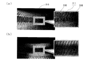
試験結果を図5(a),(b)に示す。
(a)図は、本発明によるセンサケース10の試験結果で、(b)図は、把持部12を円柱状としたセンサケース50の試験結果である。
図5(a)に示す本発明によるセンサケース10では、インナーライナー表面に削れや擦れ跡がみられないのに対して、図5(b)に示す比較例では、インナーライナーのリッジ部が回転方向に削れられてしまっているだけでなく、削れがみられない部分でも擦れた跡がみられた。
これにより、センサケースのタイヤ内面との接触する部分を曲面とすれば、センサケースが台座から外れてタイヤ内面を転がっても、タイヤ内面が傷つくことを防ぐことができることが確認された。
図4に示すように、本発明によるセンサケース10を挿入した台座20を、タイヤ内面に接着材で固定した後、ドラム40にタイヤ30を押付けながら、速度;60[km/h]にてタイヤ30を回転させるドラム試験を行い、5000[km]走行後のインナーライナーの表面状態を調べた。
なお、タイヤサイズは195/65R15で、内圧:230[kPa]、荷重;615[kg]で試験を行った。
本発明によるセンサケース10は、図1に示したものである。また、比較のため、把持部12を円柱状としたセンサケース50についても同様の試験を行った(比較例)。
なお、センサケースの重量は20gで、台座20の側壁部24の高さを半分にするなどして、センサケース10,50が台座20から外れやすい状態で試験を行った。なお、台座20の底部23と側壁部24との間に予め切り込みを入れることで、センサケース10,50が台座20から外れやすい状態にしてもよい。
試験結果を図5(a),(b)に示す。
(a)図は、本発明によるセンサケース10の試験結果で、(b)図は、把持部12を円柱状としたセンサケース50の試験結果である。
図5(a)に示す本発明によるセンサケース10では、インナーライナー表面に削れや擦れ跡がみられないのに対して、図5(b)に示す比較例では、インナーライナーのリッジ部が回転方向に削れられてしまっているだけでなく、削れがみられない部分でも擦れた跡がみられた。
これにより、センサケースのタイヤ内面との接触する部分を曲面とすれば、センサケースが台座から外れてタイヤ内面を転がっても、タイヤ内面が傷つくことを防ぐことができることが確認された。
以上、本発明を実施の形態及び実施例を用いて説明したが、本発明の技術的範囲は前記実施の形態に記載の範囲には限定されない。前記実施の形態に、多様な変更または改良を加えることが可能であることが当業者にも明らかである。そのような変更または改良を加えた形態も本発明の技術的範囲に含まれ得ることが、特許請求の範囲から明らかである。
例えば、前記実施の形態では、センサケース10が台座20に装着されている場合について説明したが、センサケース10をタイヤ内面に接着した場合でも、センサケース10を本発明の形態とすれば、センサケース10がタイヤ内面から外れて、タイヤ内面を転がった場合も、タイヤ内面が傷つくことはないことはいうまでもない。
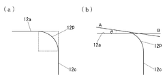
なお、前記実施の形態では、図6(a)に示すように、把持部12の側面12cと頂面12aとを、側面12cと頂面12aとに接する、円周角が90°の円弧状の断面を有する接続する曲面12pにより接続させたが、図6(b)に示すように、曲面12pの頂面12aとの接続点における接線Aの傾きと、頂面12aの曲面12pとの接続点における接線Bの傾きとが完全に一致しなくてもよく、2つの接線A,Bのなす角度θが0°~15°の範囲内であればよい。
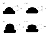
また、前記実施の形態では、上側部材である把持部12を円柱状とし、円柱状の側面12cと頂面12aとを曲面により接続させたが、図7(a),(b)に示すように、球体の一部とすれば、センサケース10を更に小型化できる。
また、図7(c),(d)に示すように、上側部材を、球体もしくは回転楕円体の2/3以上とすれば、センサケースを更に把持し易くすることができる。
なお、前記実施の形態では、図6(a)に示すように、把持部12の側面12cと頂面12aとを、側面12cと頂面12aとに接する、円周角が90°の円弧状の断面を有する接続する曲面12pにより接続させたが、図6(b)に示すように、曲面12pの頂面12aとの接続点における接線Aの傾きと、頂面12aの曲面12pとの接続点における接線Bの傾きとが完全に一致しなくてもよく、2つの接線A,Bのなす角度θが0°~15°の範囲内であればよい。
また、前記実施の形態では、上側部材である把持部12を円柱状とし、円柱状の側面12cと頂面12aとを曲面により接続させたが、図7(a),(b)に示すように、球体の一部とすれば、センサケース10を更に小型化できる。
また、図7(c),(d)に示すように、上側部材を、球体もしくは回転楕円体の2/3以上とすれば、センサケースを更に把持し易くすることができる。
以上、本願発明の実施の形態について述べたが、まとめると次のように記述できる。すなわち、本発明は、内部にタイヤの情報を取得するためのセンサが収納されたセンサケースであって、前記タイヤの内面もしくは当該センサケースを前記タイヤの内面に装着するための台座に取付けられる底面を有する下側部材と、前記下側部材の前記底面とは反対側の面から前記底面とは反対に突出する、幅が前記下側部材の幅よりも小さな上側部材とを備え、前記下部部材の側面が幅方向外側に凸な曲面から形成され、前記上側部材の側面と前記上側部材の前記底面とは反対側の面である頂面とが、前記頂面に接する曲面により接続されていることを特徴とする。
このように、センサケースがタイヤ内面もしくは台座から外れて、タイヤ内面を転がる際に、タイヤ内面との接触する箇所を曲面としたので、タイヤ内面が傷つくことを防ぐことができる。また、センサケースが、台座ごとタイヤ内面から外れてタイヤ内面を転がった場合も、上記と同様の理由で、タイヤ内面が傷つくことはない。
また、前記下側部材の側面と前記底面とを、前記底面に接する曲面により接続し、前記下側部材の側面と前記下部部材の前記底面側とは反対側の面である上面とを、前記上面に接する曲面により接続したので、センサケースがタイヤ内面に衝突した場合でも、タイヤ内面が傷つくことを防ぐことができる。
また、前記上側部材を、球体の一部、もしくは、回転楕円体の一部としたので、センサケースを小型化できる。なお、上側部材を、球体もしくは回転楕円体の2/3以上とすれば、センサケースを更に把持し易くすることができる。
このように、センサケースがタイヤ内面もしくは台座から外れて、タイヤ内面を転がる際に、タイヤ内面との接触する箇所を曲面としたので、タイヤ内面が傷つくことを防ぐことができる。また、センサケースが、台座ごとタイヤ内面から外れてタイヤ内面を転がった場合も、上記と同様の理由で、タイヤ内面が傷つくことはない。
また、前記下側部材の側面と前記底面とを、前記底面に接する曲面により接続し、前記下側部材の側面と前記下部部材の前記底面側とは反対側の面である上面とを、前記上面に接する曲面により接続したので、センサケースがタイヤ内面に衝突した場合でも、タイヤ内面が傷つくことを防ぐことができる。
また、前記上側部材を、球体の一部、もしくは、回転楕円体の一部としたので、センサケースを小型化できる。なお、上側部材を、球体もしくは回転楕円体の2/3以上とすれば、センサケースを更に把持し易くすることができる。
10 センサケース、20 ゴム台座、
10G ゴム台座付きセンサケース、11 収納部、12 把持部、
13 センサモジュール、14 センサ、15 発電素子、
16 無線機、30 タイヤ、31 インナーライナー。
10G ゴム台座付きセンサケース、11 収納部、12 把持部、
13 センサモジュール、14 センサ、15 発電素子、
16 無線機、30 タイヤ、31 インナーライナー。
Claims (3)
- 内部にタイヤの情報を取得するためのセンサが収納されたセンサケースであって、
前記タイヤの内面もしくは当該センサケースを前記タイヤの内面に装着するための台座に取付けられる底面を有する下側部材と、
前記下側部材の前記底面とは反対側の面から前記底面とは反対に突出する、幅が前記下側部材の幅よりも小さな上側部材とを備え、
前記下部部材の側面が幅方向外側に凸な曲面から形成され、
前記上側部材の側面と前記上側部材の前記底面とは反対側の面である頂面とが、前記頂面に接する曲面により接続されていることを特徴とするセンサケース。 - 前記下側部材の側面と前記底面とが、前記底面に接する曲面により接続され、
前記下側部材の側面と前記下部部材の前記底面側とは反対側の面である上面とが、前記上面に接する曲面により接続されていることを特徴とする請求項1に記載のセンサケース。 - 前記上側部材が、球体の一部、もしくは、回転楕円体の一部であることを特徴とする請求項1または請求項2に記載のセンサケース。
Priority Applications (3)
| Application Number | Priority Date | Filing Date | Title |
|---|---|---|---|
| US16/316,738 US10779424B2 (en) | 2016-07-29 | 2017-07-28 | Sensor case |
| CN201780047284.1A CN109641491B (zh) | 2016-07-29 | 2017-07-28 | 传感器壳体 |
| EP17834566.6A EP3492285B1 (en) | 2016-07-29 | 2017-07-28 | Sensor case |
Applications Claiming Priority (2)
| Application Number | Priority Date | Filing Date | Title |
|---|---|---|---|
| JP2016-150531 | 2016-07-29 | ||
| JP2016150531A JP6783088B2 (ja) | 2016-07-29 | 2016-07-29 | センサケース |
Publications (1)
| Publication Number | Publication Date |
|---|---|
| WO2018021564A1 true WO2018021564A1 (ja) | 2018-02-01 |
Family
ID=61016285
Family Applications (1)
| Application Number | Title | Priority Date | Filing Date |
|---|---|---|---|
| PCT/JP2017/027554 Ceased WO2018021564A1 (ja) | 2016-07-29 | 2017-07-28 | センサケース |
Country Status (5)
| Country | Link |
|---|---|
| US (1) | US10779424B2 (ja) |
| EP (1) | EP3492285B1 (ja) |
| JP (1) | JP6783088B2 (ja) |
| CN (1) | CN109641491B (ja) |
| WO (1) | WO2018021564A1 (ja) |
Families Citing this family (3)
| Publication number | Priority date | Publication date | Assignee | Title |
|---|---|---|---|---|
| US11835421B2 (en) * | 2019-10-31 | 2023-12-05 | Keith George Ferry | Sensor assemblies and systems for monitoring a dynamic object |
| US12344051B2 (en) | 2019-10-31 | 2025-07-01 | Cerebrum Sensor Technologies, Inc. | Sensor assemblies and systems for monitoring a dynamic object |
| CN115703309A (zh) * | 2021-08-06 | 2023-02-17 | 建大工业股份有限公司 | 设置有感测器的轮胎 |
Citations (5)
| Publication number | Priority date | Publication date | Assignee | Title |
|---|---|---|---|---|
| JP2004330842A (ja) * | 2003-05-06 | 2004-11-25 | Yokohama Rubber Co Ltd:The | タイヤ装着用センサ装置及びセンサ装着タイヤ |
| JP2005348032A (ja) * | 2004-06-02 | 2005-12-15 | Yokohama Rubber Co Ltd:The | 車載用通信アンテナ |
| WO2010067580A1 (ja) * | 2008-12-09 | 2010-06-17 | 株式会社ブリヂストン | タイヤ内情報取得装置 |
| JP2014122023A (ja) * | 2012-12-20 | 2014-07-03 | The Goodyear Tire & Rubber Co | 自己膨張タイヤ用の小型弁システム |
| JP2015160512A (ja) | 2014-02-27 | 2015-09-07 | 株式会社ブリヂストン | 機能部品取付台座、及び、タイヤ |
Family Cites Families (24)
| Publication number | Priority date | Publication date | Assignee | Title |
|---|---|---|---|---|
| FR2492742A1 (fr) * | 1980-08-05 | 1982-04-30 | Dba | Capteur de pression pour pneumatiques |
| DE3735956A1 (de) * | 1987-10-23 | 1989-05-03 | Kopp Gmbh & Co Kg Heinrich | Optisches richtmittel fuer infrarot-bewegungsmelder, punktleuchten u. dgl. |
| US6255940B1 (en) | 1999-10-01 | 2001-07-03 | The Goodyear Tire & Rubber Company | Apparatus for monitoring a condition of a tire |
| DE10243441B4 (de) | 2002-09-18 | 2004-12-30 | Continental Aktiengesellschaft | Transponder für Reifen |
| US7030743B2 (en) * | 2002-11-05 | 2006-04-18 | Tagg Technology Corp. | Tire pressure indicator providing a visual indication of tire pressure |
| US6854324B2 (en) | 2002-12-20 | 2005-02-15 | The Goodyear Tire & Rubber Company | Tire monitoring apparatus |
| FR2861650B1 (fr) * | 2003-11-05 | 2006-01-06 | Michelin Soc Tech | Dispositif de fixation d'un module de surveillance sur la surface interieure d'un pneumatique |
| DE202005005144U1 (de) * | 2005-03-31 | 2005-06-23 | Stahlgruber Otto Gruber Gmbh & Co Kg | Halterung zur Befestigung eines elektronischen Bauelements an einem Gummiartikel |
| JP2007126026A (ja) | 2005-11-04 | 2007-05-24 | Alps Electric Co Ltd | アンテナ装置 |
| EP2015942B1 (en) * | 2006-04-26 | 2016-04-06 | Pirelli Tyre S.p.A. | A tyre comprising an electronic unit |
| CN103038072B (zh) | 2010-04-09 | 2016-08-10 | 倍耐力轮胎股份公司 | 轮胎传感器装置 |
| DE102010023247A1 (de) * | 2010-06-09 | 2011-12-15 | Johnson Controls Gmbh | Ausstattungsteil mit einer Leuchtfläche |
| CN202016376U (zh) * | 2011-04-08 | 2011-10-26 | 包头市国领新技术有限公司 | 一种轮胎压力检测装置 |
| US8596117B2 (en) | 2011-10-03 | 2013-12-03 | Bridgestone Americas Tire Operations, Llc | Attachment patch for mounting various devices |
| CN102445300B (zh) * | 2011-10-09 | 2013-08-14 | 北京化工大学 | 一种动态接地压力测试装置 |
| CN102514455B (zh) * | 2011-10-31 | 2014-02-26 | 香港应用科技研究院有限公司 | 无需装配的轮胎气压监测系统 |
| ITMI20112427A1 (it) * | 2011-12-29 | 2013-06-30 | Pirelli | Dispositivo di monitoraggio per pneumatici per ruote di veicoli, pneumatico per ruote di veicoli provvisto di detto dispositivo di monitoraggio, e metodo per installare un'unita' elettronica in detto pneumatico |
| JP5837851B2 (ja) | 2012-04-24 | 2015-12-24 | 株式会社ブリヂストン | 空気入りタイヤ内面への電子部品取付構造 |
| CN202764617U (zh) * | 2012-09-11 | 2013-03-06 | 上海航盛实业有限公司 | 一种后装轮胎压力监测系统装置的底座结构 |
| US8939020B2 (en) * | 2012-12-05 | 2015-01-27 | Caterpillar Inc. | Spherical monitoring device for pneumatic tires |
| CN105531126B (zh) | 2013-08-05 | 2018-04-06 | 倍耐力轮胎股份公司 | 用于监测用于车辆车轮的轮胎的监测设备、设置有所述监测设备的轮胎以及用于在轮胎中安装电子单元的方法 |
| DE102014213060A1 (de) * | 2014-07-04 | 2016-01-07 | Continental Automotive France | Verfahren zur Montage von Reifenmodulen auf der Reifeninnenseite von Fahrzeugreifen |
| CN204623029U (zh) * | 2015-01-15 | 2015-09-09 | 深圳市豪恩汽车电子装备有限公司 | 内置式胎压传感器 |
| KR101760872B1 (ko) * | 2015-08-24 | 2017-07-24 | 한국타이어 주식회사 | 센서 패치를 구비한 공기입 타이어 및 그 제조방법 |
-
2016
- 2016-07-29 JP JP2016150531A patent/JP6783088B2/ja not_active Expired - Fee Related
-
2017
- 2017-07-28 US US16/316,738 patent/US10779424B2/en active Active
- 2017-07-28 EP EP17834566.6A patent/EP3492285B1/en active Active
- 2017-07-28 WO PCT/JP2017/027554 patent/WO2018021564A1/ja not_active Ceased
- 2017-07-28 CN CN201780047284.1A patent/CN109641491B/zh not_active Expired - Fee Related
Patent Citations (5)
| Publication number | Priority date | Publication date | Assignee | Title |
|---|---|---|---|---|
| JP2004330842A (ja) * | 2003-05-06 | 2004-11-25 | Yokohama Rubber Co Ltd:The | タイヤ装着用センサ装置及びセンサ装着タイヤ |
| JP2005348032A (ja) * | 2004-06-02 | 2005-12-15 | Yokohama Rubber Co Ltd:The | 車載用通信アンテナ |
| WO2010067580A1 (ja) * | 2008-12-09 | 2010-06-17 | 株式会社ブリヂストン | タイヤ内情報取得装置 |
| JP2014122023A (ja) * | 2012-12-20 | 2014-07-03 | The Goodyear Tire & Rubber Co | 自己膨張タイヤ用の小型弁システム |
| JP2015160512A (ja) | 2014-02-27 | 2015-09-07 | 株式会社ブリヂストン | 機能部品取付台座、及び、タイヤ |
Non-Patent Citations (1)
| Title |
|---|
| See also references of EP3492285A4 |
Also Published As
| Publication number | Publication date |
|---|---|
| JP2018016278A (ja) | 2018-02-01 |
| CN109641491B (zh) | 2021-04-20 |
| JP6783088B2 (ja) | 2020-11-11 |
| EP3492285B1 (en) | 2022-09-07 |
| EP3492285A4 (en) | 2019-06-05 |
| US20190307003A1 (en) | 2019-10-03 |
| EP3492285A1 (en) | 2019-06-05 |
| US10779424B2 (en) | 2020-09-15 |
| CN109641491A (zh) | 2019-04-16 |
Similar Documents
| Publication | Publication Date | Title |
|---|---|---|
| JP5837851B2 (ja) | 空気入りタイヤ内面への電子部品取付構造 | |
| WO2018021564A1 (ja) | センサケース | |
| CN101460320B (zh) | 具有电子单元的轮胎和将该电子单元安装到轮胎中的方法 | |
| US20200031178A1 (en) | Fitting structure between functional component accommodation case and rubber base | |
| WO2018173640A1 (ja) | 機能部品取付台座 | |
| JP5546808B2 (ja) | 扁平形電池の取付方法及び回転部分に取り付けられる装置 | |
| CN101296809B (zh) | 包括电子单元的轮胎和将电子单元安装到轮胎中的方法 | |
| JP2008049999A (ja) | 航空機タイヤ状態監視システムおよび方法 | |
| JP2004262291A (ja) | タイヤ状態監視装置用送信機のケーシング構造 | |
| CN105555553B (zh) | 充气轮胎 | |
| US20070169545A1 (en) | Fixing structure for pneumatic tire pressure sensor, and tire wheel with protector for pneumatic tire pressure sensor | |
| JP2018097183A (ja) | 車載撮像装置 | |
| JP2003182321A (ja) | タイヤ状態監視装置の送信機 | |
| JP2026503389A (ja) | タイヤケーシングに電子部材を固定する装置 | |
| JP5816709B2 (ja) | 回転部分に取り付けられる装置 | |
| TWI584971B (zh) | 自我偵測胎壓的輪胎 | |
| JP2004066848A (ja) | タイヤ状態監視装置の送信機 | |
| CN204605422U (zh) | 轮胎压力监测传感器 | |
| JP6684528B2 (ja) | 機能部品取付装置 | |
| JP2018024352A (ja) | 台座付きセンサモジュール | |
| KR100810767B1 (ko) | 타이어 공기압 모니터링 시스템용 송신기의 구조. | |
| JP2019142380A (ja) | 電子装置及びタイヤ | |
| JP2026503391A (ja) | タイヤケーシングに電子部材を固定する装置 | |
| RU2388622C1 (ru) | Шина, содержащая электронный блок, и способ установки упомянутого электронного блока в упомянутую шину | |
| JP5548402B2 (ja) | 扁平形電池の取付方法及びタイヤに取り付けられる装置 |
Legal Events
| Date | Code | Title | Description |
|---|---|---|---|
| 121 | Ep: the epo has been informed by wipo that ep was designated in this application |
Ref document number: 17834566 Country of ref document: EP Kind code of ref document: A1 |
|
| NENP | Non-entry into the national phase |
Ref country code: DE |
|
| ENP | Entry into the national phase |
Ref document number: 2017834566 Country of ref document: EP Effective date: 20190228 |