WO2018025557A1 - 電池、電池モジュール - Google Patents
電池、電池モジュール Download PDFInfo
- Publication number
- WO2018025557A1 WO2018025557A1 PCT/JP2017/024595 JP2017024595W WO2018025557A1 WO 2018025557 A1 WO2018025557 A1 WO 2018025557A1 JP 2017024595 W JP2017024595 W JP 2017024595W WO 2018025557 A1 WO2018025557 A1 WO 2018025557A1
- Authority
- WO
- WIPO (PCT)
- Prior art keywords
- battery
- electrode
- laminate
- negative electrode
- laminate film
- Prior art date
- Legal status (The legal status is an assumption and is not a legal conclusion. Google has not performed a legal analysis and makes no representation as to the accuracy of the status listed.)
- Ceased
Links
Images



Classifications
-
- H—ELECTRICITY
- H01—ELECTRIC ELEMENTS
- H01M—PROCESSES OR MEANS, e.g. BATTERIES, FOR THE DIRECT CONVERSION OF CHEMICAL ENERGY INTO ELECTRICAL ENERGY
- H01M10/00—Secondary cells; Manufacture thereof
- H01M10/04—Construction or manufacture in general
- H01M10/0413—Large-sized flat cells or batteries for motive or stationary systems with plate-like electrodes
-
- H—ELECTRICITY
- H01—ELECTRIC ELEMENTS
- H01M—PROCESSES OR MEANS, e.g. BATTERIES, FOR THE DIRECT CONVERSION OF CHEMICAL ENERGY INTO ELECTRICAL ENERGY
- H01M4/00—Electrodes
- H01M4/02—Electrodes composed of, or comprising, active material
- H01M4/36—Selection of substances as active materials, active masses, active liquids
- H01M4/58—Selection of substances as active materials, active masses, active liquids of inorganic compounds other than oxides or hydroxides, e.g. sulfides, selenides, tellurides, halogenides or LiCoFy; of polyanionic structures, e.g. phosphates, silicates or borates
- H01M4/583—Carbonaceous material, e.g. graphite-intercalation compounds or CFx
- H01M4/587—Carbonaceous material, e.g. graphite-intercalation compounds or CFx for inserting or intercalating light metals
-
- H—ELECTRICITY
- H01—ELECTRIC ELEMENTS
- H01M—PROCESSES OR MEANS, e.g. BATTERIES, FOR THE DIRECT CONVERSION OF CHEMICAL ENERGY INTO ELECTRICAL ENERGY
- H01M10/00—Secondary cells; Manufacture thereof
- H01M10/04—Construction or manufacture in general
- H01M10/0436—Small-sized flat cells or batteries for portable equipment
-
- H—ELECTRICITY
- H01—ELECTRIC ELEMENTS
- H01M—PROCESSES OR MEANS, e.g. BATTERIES, FOR THE DIRECT CONVERSION OF CHEMICAL ENERGY INTO ELECTRICAL ENERGY
- H01M10/00—Secondary cells; Manufacture thereof
- H01M10/04—Construction or manufacture in general
- H01M10/0468—Compression means for stacks of electrodes and separators
-
- H—ELECTRICITY
- H01—ELECTRIC ELEMENTS
- H01M—PROCESSES OR MEANS, e.g. BATTERIES, FOR THE DIRECT CONVERSION OF CHEMICAL ENERGY INTO ELECTRICAL ENERGY
- H01M10/00—Secondary cells; Manufacture thereof
- H01M10/05—Accumulators with non-aqueous electrolyte
- H01M10/058—Construction or manufacture
- H01M10/0585—Construction or manufacture of accumulators having only flat construction elements, i.e. flat positive electrodes, flat negative electrodes and flat separators
-
- H—ELECTRICITY
- H01—ELECTRIC ELEMENTS
- H01M—PROCESSES OR MEANS, e.g. BATTERIES, FOR THE DIRECT CONVERSION OF CHEMICAL ENERGY INTO ELECTRICAL ENERGY
- H01M4/00—Electrodes
- H01M4/02—Electrodes composed of, or comprising, active material
- H01M4/13—Electrodes for accumulators with non-aqueous electrolyte, e.g. for lithium-accumulators; Processes of manufacture thereof
-
- H—ELECTRICITY
- H01—ELECTRIC ELEMENTS
- H01M—PROCESSES OR MEANS, e.g. BATTERIES, FOR THE DIRECT CONVERSION OF CHEMICAL ENERGY INTO ELECTRICAL ENERGY
- H01M4/00—Electrodes
- H01M4/02—Electrodes composed of, or comprising, active material
- H01M4/36—Selection of substances as active materials, active masses, active liquids
- H01M4/48—Selection of substances as active materials, active masses, active liquids of inorganic oxides or hydroxides
- H01M4/485—Selection of substances as active materials, active masses, active liquids of inorganic oxides or hydroxides of mixed oxides or hydroxides for inserting or intercalating light metals, e.g. LiTi2O4 or LiTi2OxFy
-
- H—ELECTRICITY
- H01—ELECTRIC ELEMENTS
- H01M—PROCESSES OR MEANS, e.g. BATTERIES, FOR THE DIRECT CONVERSION OF CHEMICAL ENERGY INTO ELECTRICAL ENERGY
- H01M50/00—Constructional details or processes of manufacture of the non-active parts of electrochemical cells other than fuel cells, e.g. hybrid cells
- H01M50/10—Primary casings; Jackets or wrappings
- H01M50/102—Primary casings; Jackets or wrappings characterised by their shape or physical structure
- H01M50/105—Pouches or flexible bags
-
- H—ELECTRICITY
- H01—ELECTRIC ELEMENTS
- H01M—PROCESSES OR MEANS, e.g. BATTERIES, FOR THE DIRECT CONVERSION OF CHEMICAL ENERGY INTO ELECTRICAL ENERGY
- H01M50/00—Constructional details or processes of manufacture of the non-active parts of electrochemical cells other than fuel cells, e.g. hybrid cells
- H01M50/10—Primary casings; Jackets or wrappings
- H01M50/14—Primary casings; Jackets or wrappings for protecting against damage caused by external factors
-
- H—ELECTRICITY
- H01—ELECTRIC ELEMENTS
- H01M—PROCESSES OR MEANS, e.g. BATTERIES, FOR THE DIRECT CONVERSION OF CHEMICAL ENERGY INTO ELECTRICAL ENERGY
- H01M50/00—Constructional details or processes of manufacture of the non-active parts of electrochemical cells other than fuel cells, e.g. hybrid cells
- H01M50/20—Mountings; Secondary casings or frames; Racks, modules or packs; Suspension devices; Shock absorbers; Transport or carrying devices; Holders
- H01M50/202—Casings or frames around the primary casing of a single cell or a single battery
-
- H—ELECTRICITY
- H01—ELECTRIC ELEMENTS
- H01M—PROCESSES OR MEANS, e.g. BATTERIES, FOR THE DIRECT CONVERSION OF CHEMICAL ENERGY INTO ELECTRICAL ENERGY
- H01M50/00—Constructional details or processes of manufacture of the non-active parts of electrochemical cells other than fuel cells, e.g. hybrid cells
- H01M50/40—Separators; Membranes; Diaphragms; Spacing elements inside cells
-
- H—ELECTRICITY
- H01—ELECTRIC ELEMENTS
- H01M—PROCESSES OR MEANS, e.g. BATTERIES, FOR THE DIRECT CONVERSION OF CHEMICAL ENERGY INTO ELECTRICAL ENERGY
- H01M50/00—Constructional details or processes of manufacture of the non-active parts of electrochemical cells other than fuel cells, e.g. hybrid cells
- H01M50/40—Separators; Membranes; Diaphragms; Spacing elements inside cells
- H01M50/489—Separators, membranes, diaphragms or spacing elements inside the cells, characterised by their physical properties, e.g. swelling degree, hydrophilicity or shut down properties
- H01M50/491—Porosity
-
- H—ELECTRICITY
- H01—ELECTRIC ELEMENTS
- H01M—PROCESSES OR MEANS, e.g. BATTERIES, FOR THE DIRECT CONVERSION OF CHEMICAL ENERGY INTO ELECTRICAL ENERGY
- H01M10/00—Secondary cells; Manufacture thereof
- H01M10/05—Accumulators with non-aqueous electrolyte
- H01M10/052—Li-accumulators
- H01M10/0525—Rocking-chair batteries, i.e. batteries with lithium insertion or intercalation in both electrodes; Lithium-ion batteries
-
- H—ELECTRICITY
- H01—ELECTRIC ELEMENTS
- H01M—PROCESSES OR MEANS, e.g. BATTERIES, FOR THE DIRECT CONVERSION OF CHEMICAL ENERGY INTO ELECTRICAL ENERGY
- H01M4/00—Electrodes
- H01M4/02—Electrodes composed of, or comprising, active material
- H01M2004/021—Physical characteristics, e.g. porosity, surface area
-
- H—ELECTRICITY
- H01—ELECTRIC ELEMENTS
- H01M—PROCESSES OR MEANS, e.g. BATTERIES, FOR THE DIRECT CONVERSION OF CHEMICAL ENERGY INTO ELECTRICAL ENERGY
- H01M4/00—Electrodes
- H01M4/02—Electrodes composed of, or comprising, active material
- H01M2004/026—Electrodes composed of, or comprising, active material characterised by the polarity
- H01M2004/027—Negative electrodes
-
- H—ELECTRICITY
- H01—ELECTRIC ELEMENTS
- H01M—PROCESSES OR MEANS, e.g. BATTERIES, FOR THE DIRECT CONVERSION OF CHEMICAL ENERGY INTO ELECTRICAL ENERGY
- H01M50/00—Constructional details or processes of manufacture of the non-active parts of electrochemical cells other than fuel cells, e.g. hybrid cells
- H01M50/10—Primary casings; Jackets or wrappings
- H01M50/131—Primary casings; Jackets or wrappings characterised by physical properties, e.g. gas permeability, size or heat resistance
-
- H—ELECTRICITY
- H01—ELECTRIC ELEMENTS
- H01M—PROCESSES OR MEANS, e.g. BATTERIES, FOR THE DIRECT CONVERSION OF CHEMICAL ENERGY INTO ELECTRICAL ENERGY
- H01M50/00—Constructional details or processes of manufacture of the non-active parts of electrochemical cells other than fuel cells, e.g. hybrid cells
- H01M50/20—Mountings; Secondary casings or frames; Racks, modules or packs; Suspension devices; Shock absorbers; Transport or carrying devices; Holders
- H01M50/271—Lids or covers for the racks or secondary casings
-
- H—ELECTRICITY
- H01—ELECTRIC ELEMENTS
- H01M—PROCESSES OR MEANS, e.g. BATTERIES, FOR THE DIRECT CONVERSION OF CHEMICAL ENERGY INTO ELECTRICAL ENERGY
- H01M50/00—Constructional details or processes of manufacture of the non-active parts of electrochemical cells other than fuel cells, e.g. hybrid cells
- H01M50/20—Mountings; Secondary casings or frames; Racks, modules or packs; Suspension devices; Shock absorbers; Transport or carrying devices; Holders
- H01M50/289—Mountings; Secondary casings or frames; Racks, modules or packs; Suspension devices; Shock absorbers; Transport or carrying devices; Holders characterised by spacing elements or positioning means within frames, racks or packs
- H01M50/293—Mountings; Secondary casings or frames; Racks, modules or packs; Suspension devices; Shock absorbers; Transport or carrying devices; Holders characterised by spacing elements or positioning means within frames, racks or packs characterised by the material
-
- Y—GENERAL TAGGING OF NEW TECHNOLOGICAL DEVELOPMENTS; GENERAL TAGGING OF CROSS-SECTIONAL TECHNOLOGIES SPANNING OVER SEVERAL SECTIONS OF THE IPC; TECHNICAL SUBJECTS COVERED BY FORMER USPC CROSS-REFERENCE ART COLLECTIONS [XRACs] AND DIGESTS
- Y02—TECHNOLOGIES OR APPLICATIONS FOR MITIGATION OR ADAPTATION AGAINST CLIMATE CHANGE
- Y02E—REDUCTION OF GREENHOUSE GAS [GHG] EMISSIONS, RELATED TO ENERGY GENERATION, TRANSMISSION OR DISTRIBUTION
- Y02E60/00—Enabling technologies; Technologies with a potential or indirect contribution to GHG emissions mitigation
- Y02E60/10—Energy storage using batteries
-
- Y—GENERAL TAGGING OF NEW TECHNOLOGICAL DEVELOPMENTS; GENERAL TAGGING OF CROSS-SECTIONAL TECHNOLOGIES SPANNING OVER SEVERAL SECTIONS OF THE IPC; TECHNICAL SUBJECTS COVERED BY FORMER USPC CROSS-REFERENCE ART COLLECTIONS [XRACs] AND DIGESTS
- Y02—TECHNOLOGIES OR APPLICATIONS FOR MITIGATION OR ADAPTATION AGAINST CLIMATE CHANGE
- Y02P—CLIMATE CHANGE MITIGATION TECHNOLOGIES IN THE PRODUCTION OR PROCESSING OF GOODS
- Y02P70/00—Climate change mitigation technologies in the production process for final industrial or consumer products
- Y02P70/50—Manufacturing or production processes characterised by the final manufactured product
Definitions
- the present invention relates to a battery such as a lithium ion secondary battery and a battery module configured using such a battery.
- a technology that temporarily stores clean energy in the battery is used.
- solar energy stored in a battery can be used at night after the sun goes down.
- a lead battery is generally used as a battery for storing such clean energy.
- a lead storage battery is generally large in size and has a drawback of low energy density.
- lithium ion secondary batteries that can operate at room temperature and have high energy density have attracted attention.
- the lithium ion secondary battery In addition to the characteristic of high energy density, the lithium ion secondary battery also has a characteristic of excellent response because of low impedance.
- a lithium ion secondary battery for example, there is a laminated battery in which a battery element is enclosed inside a flexible film. Laminated batteries are generally flat and positive and negative electrodes are drawn out of the flexible film.
- a technique is known that makes two or more of the above laminated batteries connected in series, accommodated in a container body (casing), and modularized to be suitable for increasing the capacity.
- Patent Document 1 Japanese Patent No. 3970684
- Japanese Patent No. 3970684 Japanese Patent No. 3970684
- a battery according to the present invention contains an electrode laminate in which a positive electrode, a negative electrode, and a separator are laminated, and the electrode laminate and an electrolyte solution. And a static friction coefficient between the negative electrode and the inner surface of the laminate film exterior material is 0.1 or more.
- the battery according to the present invention is characterized in that the D90 / D10 ratio of the negative electrode active material is 1.7 or more.
- the battery according to the present invention is characterized in that the separator has a porosity of 30% or more.
- the battery according to the present invention is characterized in that a weight per unit area in the stacking direction of the electrode laminate is 1 kg / m 2 or more and 40 kg / m 2 or less.
- the battery module according to the present invention is a battery module using any of the batteries described above, and has an elastic material that applies a surface pressure of 100 kgf / m 2 or more in the stacking direction of the electrode stack. It is characterized by that.
- the battery module according to the present invention is characterized in that the Young's modulus of the elastic substance in the direction in which the surface pressure is applied is 0.1 MPa or more and 5 MPa or less.
- the battery according to the present invention includes an electrode laminate in which a positive electrode, a negative electrode, and a separator are laminated, a laminate film exterior material that contains the electrode laminate and an electrolyte, and a surface in the lamination direction of the electrode laminate.
- An elastic layer to which pressure can be applied, and a static friction coefficient between the negative electrode and the inner surface of the laminate film exterior material is 0.1 or more.
- the battery according to the present invention is characterized in that the D90 / D10 ratio of the negative electrode active material is 1.7 or more.
- the battery according to the present invention is characterized in that the separator has a porosity of 30% or more.
- the battery according to the present invention is characterized in that a weight per unit area in the stacking direction of the electrode laminate is 1 kg / m 2 or more and 40 kg / m 2 or less.
- the battery module according to the present invention is a battery module using any one of the batteries described above, wherein the elastic layer applies a surface pressure of 100 kgf / m 2 or more in the stacking direction of the electrode stack. It is characterized by that.
- the battery module according to the present invention is characterized in that the Young's modulus of the elastic layer in the direction in which the surface pressure is applied is 0.1 MPa or more and 5 MPa or less.
- the static friction coefficient between the negative electrode and the inner surface of the laminate film exterior material is 0.1 or more. According to such a battery according to the present invention, the Probability that even when an impact is applied, the laminate film exterior material breaks and the electrolyte leaks, the member that electrically connects the electrode laminate and the extraction tab breaks, or the drawer tab breaks Therefore, it is possible to provide a battery having excellent vibration resistance and impact resistance.
- the battery module of the present invention even if a long-time vibration or impact is applied to the battery module, the battery laminate film exterior material is damaged and the electrolyte leaks, the electrode laminate and the drawer tab A battery module having excellent vibration resistance and impact resistance can be provided by reducing the probability that a member that is electrically connected to each other is broken or the drawer tab is broken.
- FIG. 6 is a diagram illustrating a stacking order of components in an electrode stack 60. It is a figure which shows the structure of the electrode laminated body 60 of the battery 100 which concerns on embodiment of this invention.
- 1 is a perspective view of a battery 100 according to an embodiment of the present invention.
- 4 is a diagram illustrating a stacking order of components in a battery module 300.
- FIG. It is a perspective view of an example of the battery module 300 which concerns on embodiment of this invention.
- It is a schematic diagram of the cross section of the battery module 300 which concerns on embodiment of this invention. It is a figure explaining the weight per unit area of the lamination direction of the electrode laminated body.
- It is a schematic diagram of the cross section of the battery module 300 which concerns on other embodiment of this invention.
- FIG. 1 is a diagram for explaining the stacking order of the components in the electrode stack 60.
- FIG. 2 is a figure which shows the structure of the electrode laminated body 60 of the battery 100 which concerns on embodiment of this invention.
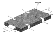
- FIG. 3 is a perspective view of the battery 100 according to the embodiment of the present invention.
- a lithium ion secondary battery that is one type of electrochemical element in which charge and discharge are performed by moving lithium ions between a negative electrode and a positive electrode will be described as an example. Can also be applied to other types of batteries.
- a battery 100 according to an embodiment of the present invention includes an electrode laminate 60 in which a plurality of positive electrodes 20 and a plurality of negative electrodes 30 are laminated via a separator 40, and an electrolyte solution (not shown) having a rectangular laminate film exterior material. The structure is accommodated in 80.
- FIG. 1 is a diagram for explaining the stacking order of the components in the electrode stack 60. As shown in FIG. 1, the positive electrode 20, the negative electrode 30, and the separator 40 are used in configuring the electrode laminate 60.
- the positive electrode 20 has a rectangular positive electrode main body portion 22 and a strip-shaped positive electrode terminal portion 24 extending from the positive electrode main body portion 22.
- a positive electrode active material 26 such as a lithium cobalt composite oxide is applied to a thin plate-like aluminum plate.
- the negative electrode 30 includes a rectangular negative electrode main body 32 and a strip-shaped negative electrode terminal 34 extending from the negative electrode main body 32.
- a negative electrode active material 36 such as graphite is applied to a thin nickel plate or copper plate.
- the separator 40 is a rectangular sheet-like member that can be impregnated with an electrolytic solution, such as a microporous film, a nonwoven fabric, or a woven fabric, made of a thermoplastic resin such as polyolefin.
- an electrolytic solution such as a microporous film, a nonwoven fabric, or a woven fabric, made of a thermoplastic resin such as polyolefin.
- the negative electrode terminal portion 34 of the positive electrode 20 is conductively connected to the positive electrode lead tab 120
- the negative electrode terminal portion of the negative electrode 30 is conductively connected to the negative electrode lead tab 130.
- An aluminum plate is used for the positive electrode extraction tab 120, and a nickel plate or a copper plate is used for the negative electrode extraction tab 130.
- a nickel plate or a copper plate is used for the negative electrode extraction tab 130.
- the negative electrode lead tab 130 is formed of a copper plate, the surface may be plated with nickel.
- the two portions on the opposite two sides of the electrode laminate 60 are fixed by the adhesive tape 65 or the like, It is preferable to ensure that the laminated state is maintained.
- the electrode laminate 60 and the electrolyte solution (not shown) formed as shown in FIG. 2 are sealed in the laminate film exterior member 80 in a state where the positive electrode extraction tab 120 and the negative electrode extraction tab 130 are extracted, A battery 100 as shown in FIG.
- the laminate film exterior member 80 is composed of two laminate films surrounding and sandwiching the electrode laminate 60 from both sides in the lamination direction, and the first sides of the opposing surfaces that overlap each other around the electrode laminate 60. 111, the second side 112, the third side 113, and the fourth side 114 are heat-welded to form a heat-welded portion (sealing region) 81, so that the electrode stack 60 is sealed together with an electrolyte (not shown). Has been.
- the positive electrode pull-out tab 120 is pulled out from the first side 111
- the negative electrode pull-out tab 130 is pulled out from the second side 112.
- the electrode laminate 60 and the electrolyte solution are sealed with two laminate films.
- the electrode laminate 60 and the electrolysis are folded so that one laminate film is folded. It is good also as a structure which seals a liquid (not shown).
- the laminate film exterior material 80 As a laminate film constituting the laminate film exterior material 80, as long as it has flexibility and can seal the electrode laminate 60 and the electrolyte (not shown) so that the electrolyte does not leak,
- the film generally used for this kind of film-clad battery can be used.
- a metal thin film layer and a heat-weldable resin layer are laminated, and further, on the surface opposite to the heat-weldable resin layer of the metal thin film layer. Furthermore, the structure which laminated
- the electrode laminate 60 and the electrolytic solution the electrode laminate 60 is surrounded by facing the heat-welding resin layer.
- metal thin film layer for example, a foil of Al, Ti, Ti alloy, Fe, stainless steel, Mg alloy or the like having a thickness of 10 ⁇ m to 100 ⁇ m can be used.
- the resin used for the heat-welding resin layer is not particularly limited as long as it can be heat-welded.
- polypropylene, polyethylene, acid-modified products thereof, polyphenylene sulfide, polyester such as polyethylene terephthalate, polyamide, An ethylene-vinyl acetate copolymer can be used.
- the thickness of the heat-welding resin layer is preferably 10 ⁇ m to 200 ⁇ m, more preferably 30 ⁇ m to 100 ⁇ m.
- the inner surface of the laminate film exterior material 80 becomes the above-described heat-weldable resin layer of the laminate film exterior material 80.
- the order of lamination is defined so that the outermost layer always becomes the negative electrode 30. Therefore, in the battery 100, the negative electrode 30 of the electrode laminate 60 and the inner surface (heat-weldable resin layer) of the laminate film exterior material 80 are in contact with each other.
- the static friction coefficient between the negative electrode 30 and the inner surface of the laminate film exterior material 80 is a predetermined value so that the electrode laminate 60 does not start to move in the laminate film exterior material 80 due to vibration or impact. It is necessary to be above.
- the inventor has experimentally found that the coefficient of static friction is preferably 0.1 or more.
- the D90 / D10 ratio is 1.7 or more in relation to the volume particle size distribution (D) of the negative electrode active material 36. This is because if the D90 / D10 ratio is less than 1.7, the surface of the negative electrode 30 becomes flat, and it becomes difficult to make the coefficient of static friction with the inner surface of the laminate film exterior material 80 to be 0.1 or more. It is.
- the porosity of the separator 40 laminated with the electrode laminate 60 is preferably 30% or more. This is because by setting the porosity to 30% or more, the flexibility of the separator 40 is improved and the Young's modulus can be kept low.
- the battery 100 as described above is generally incorporated in a casing and used as a battery module 300.
- a description will be given of an example of a casing comprising a housing case body 200 and a lid body 210. Note that the configuration related to the electrical connection portions of the positive electrode extraction tab 120 and the negative electrode extraction tab 130 in the battery module 300 is not illustrated.
- FIG. 4 is a diagram for explaining the stacking order of each component in the battery module 300.
- FIG. 5 is a perspective view of an example of the battery module 300 according to the embodiment of the present invention.
- the battery 100 is casing between the housing case body 200 and the lid body 210 so as to be sandwiched by the elastic material 150 from above and below.
- the material that can be used for the elastic material 150 is not particularly limited as long as the necessary elastic modulus and durability are satisfied.
- a material such as a sponge-like material that has been made porous.
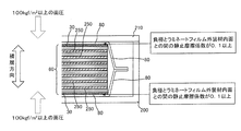
- FIG. 6 is a schematic cross-sectional view of a plane perpendicular to the stacking direction including X-X ′ in FIG.
- the outermost negative electrode 30 of the electrode stack 60 is highlighted.
- the static friction coefficient between the negative electrode 30 and the inner surface of the laminate film exterior material 80 is set to 0.1 or more.
- the elastic material 150 has a Young's modulus of 0.1 MPa to 5 MPa. Thereby, the elastic substance 150 can apply a surface pressure of 100 kgf / m 2 or more in the stacking direction of the electrode stack 60.
- FIG. 7 is a diagram showing the electrode stack 60 in the battery 100, and is a diagram illustrating the weight per unit area of the electrode stack 60 in the stacking direction.
- the weight per unit area of the electrode stack 60 in the stacking direction is 1 kg / m 2 or more and 40 kg / m 2 or less.
- the weight exceeds 40 kg / m 2 , the weight of the electrode stack 60 becomes too large, and the movement of the electrode stack 60 cannot be suppressed by frictional force. Conversely, if the weight is less than 1 kg / m 2 , Since the energy density of the battery 100 is significantly reduced, the weight is set as 1 kg / m 2 or more and 40 kg / m 2 or less.
- the static friction coefficient between the negative electrode 30 and the inner surface of the laminate film exterior material 80 is 0.1 or more. According to the battery 100 according to the present invention, Even if vibration or impact is applied for a long time, the laminate film exterior material 80 is damaged and the electrolyte solution leaks, the member that electrically connects the electrode laminate 60 and the drawer tab is broken, or the drawer is pulled out. The probability that the tab breaks or the like is reduced, and the battery 100 having excellent vibration resistance and impact resistance can be provided.
- the battery module 300 of the present invention even if the battery module 300 is subjected to vibration or impact for a long time, the laminate film exterior material 80 of the battery 100 is damaged and the electrolyte solution leaks, or the electrode laminate
- the battery module 300 having excellent vibration resistance and impact resistance can be provided by reducing the probability that the member that electrically connects 60 and the drawer tab is broken or the drawer tab is broken.
- FIG. 8 is a schematic view of a cross section of a battery module 300 according to another embodiment of the present invention, and corresponds to FIG. 6 of the previous embodiment.
- the elastic material 150 is provided outside the battery 100 in order to apply a sufficient load between the negative electrode 30 of the outermost layer of the electrode laminate 60 and the inner surface of the laminate film exterior material 80. It was done.
- the elastic layer 250 has a battery in order to apply a sufficient load between the negative electrode 30 of the outermost layer of the electrode laminate 60 and the inner surface of the laminate film exterior material 80. 100 is provided inside.
- the elastic layer 250 capable of applying a surface pressure in the stacking direction of the electrode stack 60 is provided in the electrode stack 60.
- the material used for the elastic layer 250 is not particularly limited as long as necessary physical properties and durability are satisfied.
- a porous sponge-like material can be used.
- the Young's modulus of the elastic layer 250 is 0.1 MPa or more and 5 MPa or less. Thereby, the elastic layer 250 can apply a surface pressure of 100 kgf / m 2 or more in the stacking direction of the electrode stack 60.
- a lithium ion secondary battery having a high energy density for example, there is a laminated battery in which a battery element is enclosed in a flexible film.
- the periphery of the laminated battery is fixed to the casing by adhesion or the like, or the battery pull-out tab is screwed. Even if the battery is fixed in the casing, the electrode laminate provided in the laminate film is slightly displaced.
- the electrode laminate Acts like a pendulum, and eventually the laminate film breaks and the electrolyte leaks, the member that electrically connects the electrode laminate and the drawer tab breaks, or the drawer tab breaks There was a problem. Therefore, in the battery according to the present invention, the coefficient of static friction between the negative electrode and the inner surface of the laminate film exterior material is set to 0.1 or more. Even if time vibration or impact is applied, the laminate film exterior material breaks and the electrolyte solution leaks, the member that electrically connects the electrode stack and the drawer tab breaks, or the drawer tab breaks The battery can be provided with excellent vibration resistance and impact resistance, and the industrial applicability is very large.
Landscapes
- Chemical & Material Sciences (AREA)
- Chemical Kinetics & Catalysis (AREA)
- Electrochemistry (AREA)
- General Chemical & Material Sciences (AREA)
- Engineering & Computer Science (AREA)
- Manufacturing & Machinery (AREA)
- Inorganic Chemistry (AREA)
- Secondary Cells (AREA)
- Materials Engineering (AREA)
- Sealing Battery Cases Or Jackets (AREA)
- Battery Mounting, Suspending (AREA)
- Cell Separators (AREA)
- Battery Electrode And Active Subsutance (AREA)
Abstract
優れた耐振動性・耐衝撃性を有する電池を提供するために、本発明に係る電池は、正極20と負極30とセパレーター40とが積層されてなる電極積層体60と、前記電極積層体60と電解液を収容するラミネートフィルム外装材80と、を有し、前記負極30と前記ラミネートフィルム外装材80内面との間の静止摩擦係数が0.1以上であることを特長とする。
Description
本発明は、リチウムイオン二次電池などの電池、及びそのような電池を用いて構成される電池モジュールに関する。
近年、環境問題から、戸建て住宅などの家庭用途や、輸送機器、建設機器等の産業用途に用いることが可能な、風力発電、太陽光発電等から得られるクリーンエネルギーが注目されている。しかし、クリーンエネルギーは状況に応じた出力の変動が大きいという問題を有している。例えば、太陽光発電によるエネルギーは、太陽が昇っている日中には得られるが、太陽が沈んだ後の夜間には得られない。
クリーンエネルギーの出力を安定化するために、クリーンエネルギーを一時的に電池に蓄える技術が用いられる。例えば、電池に蓄えられた太陽光エネルギーは、太陽が沈んだ後の夜間にも利用可能となる。このようなクリーンエネルギーを蓄えるための電池としては、一般的に鉛電池が使用されていたが、鉛蓄電池は一般的に大型であり、エネルギー密度が低い、という欠点がある。
そこで、近年では、常温で作動可能であり、エネルギー密度も高いリチウムイオン二次電池が注目されている。リチウムイオン二次電池は、エネルギー密度が高いという特性に加えて、インピーダンスが低いため応答性に優れている、という特徴も有する。
リチウムイオン二次電池としては、例えば、可撓性のフィルムの内部に電池要素が封入されているラミネート電池がある。ラミネート電池は、一般的に平板状であり、正極および負極が可撓性フィルムの外部に引き出されている。
上記のようなラミネート電池の2個以上を直列に接続して、容器本体(ケーシング)内に収容しモジュール化することで、大容量化に好適なものとする技術が知られている。
例えば、特許文献1(特許第3970684号公報)には、シート状に形成された4枚のシート状二次電池セルを互いに直列に接続して構成された組電池と、この組電池を収容する薄型直方体形状のケーシングとで構成された電池モジュールが開示されている。
特許第3970684号公報
特許文献1に記載されているような、ラミネート電池をケーシングに組み込んだ電池モジュールの場合には、ラミネート電池の周囲が前記ケーシングに対して接着などにより固着されていたり、電池の引き出しタブがネジ止めされていたりすることで、単位電池がケーシング内に固定されていても、ラミネートフィルム内に設けられている電極積層体が若干変位するようになっているので、電池モジュールに長時間の振動や衝撃が加わると、前記電極積層体が振り子のように作用し、ついには、ラミネートフィルムが破損し電解液が漏出したり、電極積層体と引き出しタブを導電接続している部材が破断したり、あるいは、引き出しタブが破断したりするといった問題があった。
本発明は、上記のような問題を解決するものであって、本発明に係る電池は、正極と負極とセパレーターとが積層されてなる電極積層体と、前記電極積層体と電解液を収容するラミネートフィルム外装材と、を有し、前記負極と前記ラミネートフィルム外装材内面との間の静止摩擦係数が0.1以上であることを特長とする。
また、本発明に係る電池は、前記負極の活物質のD90/D10比が1.7以上であることを特長とする。
また、本発明に係る電池は、前記セパレーターの空隙率が30%以上であることを特長とする。
また、本発明に係る電池は、前記電極積層体の積層方向の単位面積当たりの重量が1kg/m2以上40kg/m2以下であることを特長とする。
また、本発明に係る電池モジュールは、前記のいずれかに記載の電池が用いられた電池モジュールであって、前記電極積層体の積層方向に100kgf/m2以上の面圧を加える弾性物質を有することを特長とする。
また、本発明に係る電池モジュールは、面圧を加える方向における前記弾性物質のヤング率が0.1MPa以上5Mpa以下であることを特長とする。
また、本発明に係る電池は、正極と負極とセパレーターとが積層されてなる電極積層体と、前記電極積層体と電解液を収容するラミネートフィルム外装材と、前記電極積層体の積層方向に面圧を加えることができる弾性層と、を有し、前記負極と前記ラミネートフィルム外装材内面との間の静止摩擦係数が0.1以上であることを特長とする。
また、本発明に係る電池は、前記負極の活物質のD90/D10比が1.7以上であることを特長とする。
また、本発明に係る電池は、前記セパレーターの空隙率が30%以上であることを特長とする。
また、本発明に係る電池は、前記電極積層体の積層方向の単位面積当たりの重量が1kg/m2以上40kg/m2以下であることを特長とする。
また、本発明に係る電池モジュールは、前記のいずれかに記載の電池が用いられた電池モジュールであって、前記弾性層が前記電極積層体の積層方向に100kgf/m2以上の面圧を加えることを特長とする。
また、本発明に係る電池モジュールは、面圧を加える方向における前記弾性層のヤング率が0.1MPa以上5Mpa以下であることを特長とする。
本発明に係る電池は、前記負極と前記ラミネートフィルム外装材内面との間の静止摩擦係数が0.1以上であり、このような本発明に係る電池によれば、電池に長時間の振動や衝撃が加わったとしても、ラミネートフィルム外装材が破損し電解液が漏出したり、電極積層体と引き出しタブとを導電接続している部材が破断したり、あるいは、引き出しタブが破断したりする確率が低減し、優れた耐振動性・耐衝撃性を有する電池を提供できる。
また、本発明に係る電池モジュールによれば、電池モジュールに長時間の振動や衝撃が加わったとしても、電池のラミネートフィルム外装材が破損し電解液が漏出したり、電極積層体と引き出しタブとを導電接続している部材が破断したり、あるいは、引き出しタブが破断したりする確率が低減し、優れた耐振動性・耐衝撃性を有する電池モジュールを提供できる。
以下、本発明の実施の形態を図面を参照しつつ説明する。図1は電極積層体60における各構成の積層順序を説明する図である。また、図2は本発明の実施形態に係る電池100の電極積層体60の構成を示す図である。また、図3は本発明の実施形態に係る電池100の斜視図である。
本実施形態においては、電池100として、リチウムイオンが負極と正極とを移動することにより充放電が行われる、電気化学素子の1種であるリチウムイオン二次電池を例に説明するが、本発明は他の種類の電池にも適用することができる。
本発明の実施形態に係る電池100は、複数の正極20と複数の負極30とがセパレーター40を介して積層された電極積層体60、および電解液(不図示)が、矩形のラミネートフィルム外装材80内に収容された構造となっている。
図1は電極積層体60における各構成の積層順序を説明する図である。図1に示すように、電極積層体60を構成する上では、正極20、負極30、セパレーター40が用いられている。
正極20は、矩形状の正極本体部22と、正極本体部22から延出する短冊状の正極端子部24とを有している。正極本体部22においては、薄板状のアルミニウム板にリチウムコバルト複合酸化物等の正極活物質26が塗布されている。
また、負極30は、矩形状の負極本体部32と、負極本体部32から延出する短冊状の負極端子部34とを有している。負極本体部32においては、薄板状のニッケル板又は銅板にグラファイト等の負極活物質36が塗布されている。
セパレーター40は、ポリオレフィン等の熱可塑性樹脂から作られた、マイクロポーラスフィルム(微多孔フィルム)、不織布あるいは織布など、電解液を含浸することができる矩形のシート状の部材である。
上記のような各構成が、電極積層体60として積層されると、正極20に形成された正極端子部24の全ては、負極30に形成された負極端子部34の全ては、それぞれ超音波溶着などにより互いに固着される。
さらに、図2に示すように、正極20の負極端子部34は、正極引き出しタブ120に導電接続され、また、負極30の負極端子部は、負極引き出しタブ130に導電接続される。
正極引き出しタブ120にはアルミニウム板が用いられ、負極引き出しタブ130にはニッケル板または銅板が用いられる。負極引き出しタブ130を銅板で構成する場合、表面にニッケルめっきを施してもよい。
また、上記のような各構成が、電極積層体60として積層されると、図2に示すように、電極積層体60の対向する2辺側の2箇所において接着テープ65などによる固着を行い、積層状態の保持を確実とするようにすることが好ましい。
図2に示されるように形成された電極積層体60及び電解液(不図示)は、正極引き出しタブ120及び負極引き出しタブ130が引き出された状態で、ラミネートフィルム外装材80内に封止され、図3に示されるような電池100とされる。
本実施形態では、ラミネートフィルム外装材80は、電極積層体60をその積層方向両側から挟んで包囲する2枚のラミネートフィルムからなり、電極積層体60の周囲で重なり合った対向面同士における第1辺111、第2辺112、第3辺113、第4辺114を熱溶着し、熱溶着部(封止領域)81を形成することで、電極積層体60が電解液(不図示)と共に封止されている。ラミネートフィルム外装材80において、第1辺111からは正極引き出しタブ120が、また、第2辺112からは負極引き出しタブ130が引き出される。
なお、本実施形態では、2枚のラミネートフィルムで電極積層体60と電解液(不図示)とを封止する構成としたが、1枚のラミネートフィルを折り返すようにして電極積層体60と電解液(不図示)とを封止する構成としてもよい。
ラミネートフィルム外装材80を構成するラミネートフィルムとしては、柔軟性を有しており、かつ電解液が漏洩しないように、電極積層体60と電解液(不図示)を封止できるものであれば、この種のフィルム外装電池に一般に用いられるフィルムを用いることができる。
ラミネートフィルム外装材80に用いられるラミネートフィルムの代表的な層構成としては、金属薄膜層と熱溶着性樹脂層とを積層し、さらに、金属薄膜層の熱溶着性樹脂層と反対側の面にさらに、ポリエチレンテレフタレートなどのポリエステルやナイロン等のフィルムからなる保護用樹脂層を積層した構成が挙げられる。電極積層体60、電解液を封止するに際しては、熱溶着性樹脂層を対向させて電極積層体60を包囲する。
金属薄膜層としては、例えば、厚さ10μm~100μmの、Al、Ti、Ti合金、Fe、ステンレス、Mg合金などの箔を用いることができる。
熱溶着性樹脂層に用いられる樹脂としては、熱溶着が可能な樹脂であれば特に制限はなく、例えば、ポリプロピレン、ポリエチレン、これらの酸変成物、ポリフェニレンサルファイド、ポリエチレンテレフタレートなどのポリエステル等、ポリアミド、エチレン-酢酸ビニル共重合体などが使用できる。熱溶着性樹脂層の厚さは10μm~200μmが好ましく、より好ましくは30μm~100μmである。
ラミネートフィルム外装材80の内面は、ラミネートフィルム外装材80の上記のような熱溶着性樹脂層となる。一方、電極積層体60においては、最外層には必ず負極30となるように、積層順が規定されている。したがって、電池100においては、電極積層体60の負極30と、ラミネートフィルム外装材80内面(熱溶着性樹脂層)とが当接した状態した状態となっている。
ここで、電池100において、電極積層体60が振動や衝撃によって、ラミネートフィルム外装材80内で動き出さないためには、負極30と、ラミネートフィルム外装材80内面との間の静止摩擦係数が所定値以上である必要がある。発明者は、この静止摩擦係数が0.1以上であることが好ましいことを実験的に見いだした。
このような静止摩擦係数を得るためには、負極活物質36の体積粒度分布(D)に関連して、D90/D10比が1.7以上であることが好ましい。これは、D90/D10比が1.7未満であると、負極30の表面が平坦となり、ラミネートフィルム外装材80内面との間の静止摩擦係数を0.1以上とすることが困難となるからである。
また、電極積層体60で積層されているセパレーター40の空隙率は、30%以上であることが好ましい。これは、空隙率を30%以上とすることでセパレーター40の柔軟性が向上し、ヤング率を低く抑えることが可能となるからである。
上記のような電池100は、ケーシング内に組み込まれ、電池モジュール300として利用されることが一般的である。このようなケーシングの一例として、収容ケース体200と蓋体210とからなるものを例に説明する。なお、電池モジュール300における正極引き出しタブ120や負極引き出しタブ130の電気接続部に関連する構成については図示省略する。
図4は電池モジュール300における各構成の積層順序を説明する図である。また、図5は本発明の実施形態に係る電池モジュール300の一例の斜視図である。本実施形態においては、図に示されるように、収容ケース体200と蓋体210との間で、電池100は上下から弾性物質150によって狭持されるようにしてケーシングされている。
弾性物質150としては、必要な弾性率および耐久性を満たす限り、用い得る材質が特に限定されるものではないが、例えばイソプレンゴム、ブタジエンゴム、クロロプレンゴム、ニトリルゴム、アクリルゴム、フッ素ゴム、ウレタンゴム、シリコーンゴムなどのゴム状高分子体や、これらを発泡多孔質化したスポンジ状質物、またはその他のポリオレフィン、ハロゲン化ポリオレフィンなどの高分子を相分離、化学処理、粒子融着、繊維化などにより多孔質化したスポンジ状質物などの材質のものを用いることができる。
図6は、図5のX-X’を含む、積層方向に対して垂直な面の模式的な断面図である。図6において、電極積層体60の最外層の負極30については強調的な表示を行っている。本発明においては、前述したように、負極30とラミネートフィルム外装材80内面との間の静止摩擦係数は0.1以上として設定されている。
また、電極積層体60の最外層の負極30と、ラミネートフィルム外装材80内面との間に十分な荷重をかけるために、弾性物質150のヤング率は0.1MPa以上5Mpa以下とする。これにより、弾性物質150は、電極積層体60の積層方向に100kgf/m2以上の面圧を加えることが可能となる。
また、図7は電池100における電極積層体60を抜き出して示す図であり、電極積層体60の積層方向の単位面積当たりの重量を説明する図である。本発明においては、電極積層体60の積層方向の単位面積当たりの重量は1kg/m2以上40kg/m2以下とされている。
前記重量が40kg/m2を越えると、電極積層体60の重量が大きくなりすぎ、摩擦力で電極積層体60の動きを抑えきれなくなり、逆に、前記重量が1kg/m2を下回ると、電池100としてのエネルギー密度が大幅に低下してしまうこととなるので、前記重量は1kg/m2以上40kg/m2以下として設定されている。
本発明に係る電池100は、前記負極30と前記ラミネートフィルム外装材80内面との間の静止摩擦係数が0.1以上であり、このような本発明に係る電池100によれば、電池100に長時間の振動や衝撃が加わったとしても、ラミネートフィルム外装材80が破損し電解液が漏出したり、電極積層体60と引き出しタブとを導電接続している部材が破断したり、あるいは、引き出しタブが破断したりする確率が低減し、優れた耐振動性・耐衝撃性を有する電池100を提供できる。
また、本発明に係る電池モジュール300によれば、電池モジュール300に長時間の振動や衝撃が加わったとしても、電池100のラミネートフィルム外装材80が破損し電解液が漏出したり、電極積層体60と引き出しタブとを導電接続している部材が破断したり、あるいは、引き出しタブが破断したりする確率が低減し、優れた耐振動性・耐衝撃性を有する電池モジュール300を提供できる。
次に、本発明の他の実施形態について説明する。図8は本発明の他の実施形態に係る電池モジュール300の断面の模式図であり、先の実施形態の図6に相当する図である。
以下、先の実施形態と、他の実施形態の相違点ついて説明する。先の実施形態の電池100においては、電極積層体60の最外層の負極30と、ラミネートフィルム外装材80内面との間に十分な荷重をかけるために、弾性物質150が電池100の外部に設けられていた。
これに対して、他の実施形態の電池100においては、電極積層体60の最外層の負極30と、ラミネートフィルム外装材80内面との間に十分な荷重をかけるために、弾性層250が電池100の内部に設けられていることを特長としている。
上記のような相違点以外の構成は、先の実施形態と、他の実施形態とで異なるところはない。他の実施形態においては、図8に示すように、電極積層体60の積層方向に面圧を加えることができる弾性層250は、電極積層体60中に設けられている。
弾性層250に用いる材質としては、必要な物性および耐久性を満たす限り、特に限定されるものではないが、例えば、イソプレンゴム、ブタジエンゴム、クロロプレンゴム、ニトリルゴム、アクリルゴム、フッ素ゴム、ウレタンゴム、シリコーンゴムなどのゴム状高分子体や、これらを発泡多孔質化したスポンジ状質物、またはその他のポリオレフィン、ハロゲン化ポリオレフィンなどの高分子を相分離、化学処理、粒子融着、繊維化などにより多孔質化したスポンジ状質物などを用いることができる。
また、弾性層250のヤング率は0.1MPa以上5Mpa以下とする。これにより、弾性層250は、電極積層体60の積層方向に100kgf/m2以上の面圧を加えることが可能となる。
以上のような他の実施形態に係る電池100、及び、このような電池100を用いた電池モジュール300によっても、先の実施形態と同様の効果を享受することができる。
近年、エネルギー密度も高いリチウムイオン二次電池としては、例えば、可撓性のフィルムの内部に電池要素が封入されているラミネート電池がある。このようなラミネート電池をケーシングに組み込んだ電池モジュールの場合には、ラミネート電池の周囲が前記ケーシングに対して接着などにより固着されていたり、電池の引き出しタブがネジ止めされていたりすることで、単位電池がケーシング内に固定されていても、ラミネートフィルム内に設けられている電極積層体が若干変位するようになっているので、電池モジュールに長時間の振動や衝撃が加わると、前記電極積層体が振り子のように作用し、ついには、ラミネートフィルムが破損し電解液が漏出したり、電極積層体と引き出しタブを導電接続している部材が破断したり、あるいは、引き出しタブが破断したりするといった問題があった。そこで、本発明に係る電池では、前記負極と前記ラミネートフィルム外装材内面との間の静止摩擦係数が0.1以上とされており、このような本発明に係る電池によれば、電池に長時間の振動や衝撃が加わったとしても、ラミネートフィルム外装材が破損し電解液が漏出したり、電極積層体と引き出しタブとを導電接続している部材が破断したり、あるいは、引き出しタブが破断したりする確率が低減し、優れた耐振動性・耐衝撃性を有する電池を提供でき、産業上の利用性が非常に大きい。
20・・・正極
22・・・正極本体部
24・・・正極端子部
26・・・正極活物質
30・・・負極
32・・・負極本体部
34・・・負極端子部
36・・・負極活物質
40・・・セパレーター
42・・・セパレーター本体部
44・・・セパレーター延出片
60・・・電極積層体
65・・・接着テープ
80・・・ラミネートフィルム外装材
81・・・熱溶着部(封止領域)
100・・・電池
110・・・電池本体部
111・・・第1辺
112・・・第2辺
113・・・第3辺
114・・・第4辺
120・・・正極引き出しタブ
130・・・負極引き出しタブ
150・・・弾性物質
200・・・収容ケース体
210・・・蓋体
250・・・弾性層
300・・・電池モジュール
22・・・正極本体部
24・・・正極端子部
26・・・正極活物質
30・・・負極
32・・・負極本体部
34・・・負極端子部
36・・・負極活物質
40・・・セパレーター
42・・・セパレーター本体部
44・・・セパレーター延出片
60・・・電極積層体
65・・・接着テープ
80・・・ラミネートフィルム外装材
81・・・熱溶着部(封止領域)
100・・・電池
110・・・電池本体部
111・・・第1辺
112・・・第2辺
113・・・第3辺
114・・・第4辺
120・・・正極引き出しタブ
130・・・負極引き出しタブ
150・・・弾性物質
200・・・収容ケース体
210・・・蓋体
250・・・弾性層
300・・・電池モジュール
Claims (12)
- 正極と負極とセパレーターとが積層されてなる電極積層体と、
前記電極積層体と電解液を収容するラミネートフィルム外装材と、を有し、
前記負極と前記ラミネートフィルム外装材内面との間の静止摩擦係数が0.1以上であることを特長とする電池。 - 前記負極の活物質のD90/D10比が1.7以上であることを特長とする請求項1に記載の電池。
- 前記セパレーターの空隙率が30%以上であることを特長とする請求項1又は請求項2に記載の電池。
- 前記電極積層体の積層方向の単位面積当たりの重量が1kg/m2以上40kg/m2以下であることを特長とする請求項1乃至請求項3のいずれか1項に記載の電池。
- 請求項1乃至請求項4のいずれか1項に記載の電池が用いられた電池モジュールであって、
前記電極積層体の積層方向に100kgf/m2以上の面圧を加える弾性物質を有することを特長とする電池モジュール。 - 面圧を加える方向における前記弾性物質のヤング率が0.1MPa以上5Mpa以下であることを特長とする請求項5に記載の電池モジュール。
- 正極と負極とセパレーターとが積層されてなる電極積層体と、
前記電極積層体と電解液を収容するラミネートフィルム外装材と、
前記電極積層体の積層方向に面圧を加えることができる弾性層と、を有し、
前記負極と前記ラミネートフィルム外装材内面との間の静止摩擦係数が0.1以上であることを特長とする電池。 - 前記負極の活物質のD90/D10比が1.7以上であることを特長とする請求項7に記載の電池。
- 前記セパレーターの空隙率が30%以上であることを特長とする請求項7又は請求項8に記載の電池。
- 前記電極積層体の積層方向の単位面積当たりの重量が1kg/m2以上40kg/m2以下であることを特長とする請求項7乃至請求項9のいずれか1項に記載の電池。
- 請求項7乃至請求項10のいずれか1項に記載の電池が用いられた電池モジュールであって、
前記弾性層が前記電極積層体の積層方向に100kgf/m2以上の面圧を加えることを特長とする電池モジュール。 - 面圧を加える方向における前記弾性層のヤング率が0.1MPa以上5Mpa以下であることを特長とする請求項11に記載の電池モジュール。
Priority Applications (4)
| Application Number | Priority Date | Filing Date | Title |
|---|---|---|---|
| JP2018531784A JP6952036B2 (ja) | 2016-08-05 | 2017-07-05 | 電池、電池モジュール |
| CN201780048567.8A CN109565071A (zh) | 2016-08-05 | 2017-07-05 | 电池和电池模块 |
| EP17836664.7A EP3496200A4 (en) | 2016-08-05 | 2017-07-05 | Battery and battery module |
| US16/322,988 US20190181392A1 (en) | 2016-08-05 | 2017-07-05 | Battery and battery module |
Applications Claiming Priority (2)
| Application Number | Priority Date | Filing Date | Title |
|---|---|---|---|
| JP2016154782 | 2016-08-05 | ||
| JP2016-154782 | 2016-08-05 |
Publications (1)
| Publication Number | Publication Date |
|---|---|
| WO2018025557A1 true WO2018025557A1 (ja) | 2018-02-08 |
Family
ID=61073739
Family Applications (1)
| Application Number | Title | Priority Date | Filing Date |
|---|---|---|---|
| PCT/JP2017/024595 Ceased WO2018025557A1 (ja) | 2016-08-05 | 2017-07-05 | 電池、電池モジュール |
Country Status (5)
| Country | Link |
|---|---|
| US (1) | US20190181392A1 (ja) |
| EP (1) | EP3496200A4 (ja) |
| JP (1) | JP6952036B2 (ja) |
| CN (1) | CN109565071A (ja) |
| WO (1) | WO2018025557A1 (ja) |
Cited By (3)
| Publication number | Priority date | Publication date | Assignee | Title |
|---|---|---|---|---|
| WO2019151230A1 (ja) | 2018-01-30 | 2019-08-08 | 株式会社Ihi | 充填材、その製造方法及び液膜形成構造 |
| JP2021128845A (ja) * | 2020-02-12 | 2021-09-02 | パナソニック株式会社 | 非水電解質二次電池及び二次電池モジュール |
| JP2023106356A (ja) * | 2022-01-20 | 2023-08-01 | 三星エスディアイ株式会社 | 単位スタックセル構造体及びそれを含む全固体2次電池 |
Families Citing this family (3)
| Publication number | Priority date | Publication date | Assignee | Title |
|---|---|---|---|---|
| CN115443576B (zh) * | 2020-07-30 | 2025-04-29 | 理百思特有限公司 | 外装材料、在外装材料形成图案的方法及包括外装材料的电池的制造方法 |
| DE102020130139A1 (de) | 2020-11-16 | 2022-05-19 | Bayerische Motoren Werke Aktiengesellschaft | Batteriemodul mit einer Vielzahl von Batteriezellen |
| FR3156593A1 (fr) * | 2023-12-06 | 2025-06-13 | Saft | Couche tampon pour éléments électrochimiques |
Citations (9)
| Publication number | Priority date | Publication date | Assignee | Title |
|---|---|---|---|---|
| JP2003132936A (ja) * | 2001-10-24 | 2003-05-09 | Mitsubishi Electric Corp | 2次電池およびその製造方法 |
| JP2010238687A (ja) * | 2009-03-30 | 2010-10-21 | Fdk Corp | 蓄電デバイス |
| JP2011060456A (ja) * | 2009-09-07 | 2011-03-24 | Nissan Motor Co Ltd | 双極型電池 |
| JP2011222388A (ja) * | 2010-04-13 | 2011-11-04 | Sharp Corp | 積層型二次電池 |
| JP2011233519A (ja) * | 2010-04-09 | 2011-11-17 | Kawaken Fine Chemicals Co Ltd | 非水電解液電池用セパレータおよびリチウムイオン二次電池 |
| WO2014034350A1 (ja) * | 2012-08-27 | 2014-03-06 | Necエナジーデバイス株式会社 | 電池モジュール |
| JP2014089855A (ja) * | 2012-10-30 | 2014-05-15 | Hitachi Maxell Ltd | 非水二次電池用負極活物質および非水二次電池 |
| WO2014157416A1 (ja) * | 2013-03-26 | 2014-10-02 | 日産自動車株式会社 | 非水電解質二次電池 |
| JP2016062810A (ja) * | 2014-09-19 | 2016-04-25 | 株式会社東芝 | 非水電解質二次電池用負極およびそれを備えた非水電解質二次電池 |
Family Cites Families (5)
| Publication number | Priority date | Publication date | Assignee | Title |
|---|---|---|---|---|
| JP5114950B2 (ja) * | 2006-02-13 | 2013-01-09 | 日産自動車株式会社 | 電池モジュール、組電池及びそれらの電池を搭載した車両 |
| JP5502707B2 (ja) * | 2009-11-20 | 2014-05-28 | 三菱樹脂株式会社 | 積層多孔フィルム、電池用セパレータおよび電池 |
| US9123955B2 (en) * | 2012-04-06 | 2015-09-01 | Samsung Sdi Co., Ltd. | Negative active material, lithium battery including the material, and method for manufacturing the material |
| WO2014175355A1 (ja) * | 2013-04-26 | 2014-10-30 | 日産自動車株式会社 | 非水電解質二次電池 |
| JP6760071B2 (ja) * | 2014-10-16 | 2020-09-23 | 凸版印刷株式会社 | 蓄電デバイス用外装材及び蓄電デバイス |
-
2017
- 2017-07-05 EP EP17836664.7A patent/EP3496200A4/en not_active Withdrawn
- 2017-07-05 WO PCT/JP2017/024595 patent/WO2018025557A1/ja not_active Ceased
- 2017-07-05 US US16/322,988 patent/US20190181392A1/en not_active Abandoned
- 2017-07-05 CN CN201780048567.8A patent/CN109565071A/zh active Pending
- 2017-07-05 JP JP2018531784A patent/JP6952036B2/ja active Active
Patent Citations (9)
| Publication number | Priority date | Publication date | Assignee | Title |
|---|---|---|---|---|
| JP2003132936A (ja) * | 2001-10-24 | 2003-05-09 | Mitsubishi Electric Corp | 2次電池およびその製造方法 |
| JP2010238687A (ja) * | 2009-03-30 | 2010-10-21 | Fdk Corp | 蓄電デバイス |
| JP2011060456A (ja) * | 2009-09-07 | 2011-03-24 | Nissan Motor Co Ltd | 双極型電池 |
| JP2011233519A (ja) * | 2010-04-09 | 2011-11-17 | Kawaken Fine Chemicals Co Ltd | 非水電解液電池用セパレータおよびリチウムイオン二次電池 |
| JP2011222388A (ja) * | 2010-04-13 | 2011-11-04 | Sharp Corp | 積層型二次電池 |
| WO2014034350A1 (ja) * | 2012-08-27 | 2014-03-06 | Necエナジーデバイス株式会社 | 電池モジュール |
| JP2014089855A (ja) * | 2012-10-30 | 2014-05-15 | Hitachi Maxell Ltd | 非水二次電池用負極活物質および非水二次電池 |
| WO2014157416A1 (ja) * | 2013-03-26 | 2014-10-02 | 日産自動車株式会社 | 非水電解質二次電池 |
| JP2016062810A (ja) * | 2014-09-19 | 2016-04-25 | 株式会社東芝 | 非水電解質二次電池用負極およびそれを備えた非水電解質二次電池 |
Non-Patent Citations (1)
| Title |
|---|
| See also references of EP3496200A4 * |
Cited By (5)
| Publication number | Priority date | Publication date | Assignee | Title |
|---|---|---|---|---|
| WO2019151230A1 (ja) | 2018-01-30 | 2019-08-08 | 株式会社Ihi | 充填材、その製造方法及び液膜形成構造 |
| JP2021128845A (ja) * | 2020-02-12 | 2021-09-02 | パナソニック株式会社 | 非水電解質二次電池及び二次電池モジュール |
| JP7403337B2 (ja) | 2020-02-12 | 2023-12-22 | パナソニックホールディングス株式会社 | 非水電解質二次電池及び二次電池モジュール |
| JP2023106356A (ja) * | 2022-01-20 | 2023-08-01 | 三星エスディアイ株式会社 | 単位スタックセル構造体及びそれを含む全固体2次電池 |
| JP7590471B2 (ja) | 2022-01-20 | 2024-11-26 | 三星エスディアイ株式会社 | 単位スタックセル構造体及びそれを含む全固体2次電池 |
Also Published As
| Publication number | Publication date |
|---|---|
| JP6952036B2 (ja) | 2021-10-20 |
| US20190181392A1 (en) | 2019-06-13 |
| CN109565071A (zh) | 2019-04-02 |
| EP3496200A4 (en) | 2020-04-22 |
| EP3496200A1 (en) | 2019-06-12 |
| JPWO2018025557A1 (ja) | 2019-05-30 |
Similar Documents
| Publication | Publication Date | Title |
|---|---|---|
| JP6952036B2 (ja) | 電池、電池モジュール | |
| US11264665B1 (en) | Battery housings for accommodating swelling of electrode assemblies | |
| JP4424053B2 (ja) | ラミネート型二次電池、およびその組電池 | |
| JP3730981B2 (ja) | フィルム外装電池および組電池 | |
| KR101408409B1 (ko) | 정치용 전력 시스템 및 정치용 전력 장치의 제조 방법 | |
| US10446819B2 (en) | Apparatus and method for directed vent gas expulsion in battery cells | |
| JP2018527719A (ja) | 二次電池用パウチ外装材 | |
| KR20130119457A (ko) | 다방향성 리드-탭 구조를 가진 리튬 이차전지 | |
| KR101139016B1 (ko) | 다방향성 리드-탭 구조를 가진 리튬 이차 전지 | |
| JP2009187889A (ja) | 電池ケース及び組電池 | |
| JP2010086753A (ja) | 蓄電デバイス | |
| JP7351227B2 (ja) | 蓄電装置 | |
| KR20130000360A (ko) | 파우치 및 파우치형 이차전지 | |
| JP7414129B2 (ja) | 二次電池 | |
| JP5228482B2 (ja) | 電気デバイス | |
| JP2016039094A (ja) | 積層型電池及び電池モジュール | |
| KR101317535B1 (ko) | 2차 전지 및 이것을 사용한 조전지 | |
| JP7533608B2 (ja) | 二次電池 | |
| KR20170058047A (ko) | 일회용 가스 포집부를 포함하고 있는 파우치형 전지케이스 및 이를 포함하는 이차전지의 제조방법 | |
| KR20220002540A (ko) | 셀 배터리 | |
| JPWO2017047473A6 (ja) | 電池 | |
| CN107851742A (zh) | 电池 | |
| JP2011070975A (ja) | ラミネート型電池の押圧構造 | |
| KR20120038075A (ko) | 파우치형 슈퍼커패시터 고정장치 | |
| JP6191524B2 (ja) | 蓄電装置 |
Legal Events
| Date | Code | Title | Description |
|---|---|---|---|
| WWE | Wipo information: entry into national phase |
Ref document number: 2018531784 Country of ref document: JP |
|
| 121 | Ep: the epo has been informed by wipo that ep was designated in this application |
Ref document number: 17836664 Country of ref document: EP Kind code of ref document: A1 |
|
| NENP | Non-entry into the national phase |
Ref country code: DE |
|
| ENP | Entry into the national phase |
Ref document number: 2017836664 Country of ref document: EP Effective date: 20190305 |