WO2018028366A1 - 译码方法及设备、译码器 - Google Patents
译码方法及设备、译码器 Download PDFInfo
- Publication number
- WO2018028366A1 WO2018028366A1 PCT/CN2017/092179 CN2017092179W WO2018028366A1 WO 2018028366 A1 WO2018028366 A1 WO 2018028366A1 CN 2017092179 W CN2017092179 W CN 2017092179W WO 2018028366 A1 WO2018028366 A1 WO 2018028366A1
- Authority
- WO
- WIPO (PCT)
- Prior art keywords
- decoding
- path
- bits
- value
- paths
- Prior art date
- Legal status (The legal status is an assumption and is not a legal conclusion. Google has not performed a legal analysis and makes no representation as to the accuracy of the status listed.)
- Ceased
Links
Images



Classifications
-
- H—ELECTRICITY
- H04—ELECTRIC COMMUNICATION TECHNIQUE
- H04L—TRANSMISSION OF DIGITAL INFORMATION, e.g. TELEGRAPHIC COMMUNICATION
- H04L1/00—Arrangements for detecting or preventing errors in the information received
- H04L1/004—Arrangements for detecting or preventing errors in the information received by using forward error control
- H04L1/0045—Arrangements at the receiver end
- H04L1/0052—Realisations of complexity reduction techniques, e.g. pipelining or use of look-up tables
-
- H—ELECTRICITY
- H03—ELECTRONIC CIRCUITRY
- H03M—CODING; DECODING; CODE CONVERSION IN GENERAL
- H03M13/00—Coding, decoding or code conversion, for error detection or error correction; Coding theory basic assumptions; Coding bounds; Error probability evaluation methods; Channel models; Simulation or testing of codes
- H03M13/37—Decoding methods or techniques, not specific to the particular type of coding provided for in groups H03M13/03 - H03M13/35
- H03M13/39—Sequence estimation, i.e. using statistical methods for the reconstruction of the original codes
- H03M13/3905—Maximum a posteriori probability [MAP] decoding or approximations thereof based on trellis or lattice decoding, e.g. forward-backward algorithm, log-MAP decoding, max-log-MAP decoding
- H03M13/3927—Log-Likelihood Ratio [LLR] computation by combination of forward and backward metrics into LLRs
-
- H—ELECTRICITY
- H03—ELECTRONIC CIRCUITRY
- H03M—CODING; DECODING; CODE CONVERSION IN GENERAL
- H03M13/00—Coding, decoding or code conversion, for error detection or error correction; Coding theory basic assumptions; Coding bounds; Error probability evaluation methods; Channel models; Simulation or testing of codes
-
- H—ELECTRICITY
- H03—ELECTRONIC CIRCUITRY
- H03M—CODING; DECODING; CODE CONVERSION IN GENERAL
- H03M13/00—Coding, decoding or code conversion, for error detection or error correction; Coding theory basic assumptions; Coding bounds; Error probability evaluation methods; Channel models; Simulation or testing of codes
- H03M13/03—Error detection or forward error correction by redundancy in data representation, i.e. code words containing more digits than the source words
- H03M13/05—Error detection or forward error correction by redundancy in data representation, i.e. code words containing more digits than the source words using block codes, i.e. a predetermined number of check bits joined to a predetermined number of information bits
- H03M13/09—Error detection only, e.g. using cyclic redundancy check [CRC] codes or single parity bit
-
- H—ELECTRICITY
- H03—ELECTRONIC CIRCUITRY
- H03M—CODING; DECODING; CODE CONVERSION IN GENERAL
- H03M13/00—Coding, decoding or code conversion, for error detection or error correction; Coding theory basic assumptions; Coding bounds; Error probability evaluation methods; Channel models; Simulation or testing of codes
- H03M13/03—Error detection or forward error correction by redundancy in data representation, i.e. code words containing more digits than the source words
- H03M13/05—Error detection or forward error correction by redundancy in data representation, i.e. code words containing more digits than the source words using block codes, i.e. a predetermined number of check bits joined to a predetermined number of information bits
- H03M13/09—Error detection only, e.g. using cyclic redundancy check [CRC] codes or single parity bit
- H03M13/091—Parallel or block-wise CRC computation
-
- H—ELECTRICITY
- H03—ELECTRONIC CIRCUITRY
- H03M—CODING; DECODING; CODE CONVERSION IN GENERAL
- H03M13/00—Coding, decoding or code conversion, for error detection or error correction; Coding theory basic assumptions; Coding bounds; Error probability evaluation methods; Channel models; Simulation or testing of codes
- H03M13/03—Error detection or forward error correction by redundancy in data representation, i.e. code words containing more digits than the source words
- H03M13/05—Error detection or forward error correction by redundancy in data representation, i.e. code words containing more digits than the source words using block codes, i.e. a predetermined number of check bits joined to a predetermined number of information bits
- H03M13/11—Error detection or forward error correction by redundancy in data representation, i.e. code words containing more digits than the source words using block codes, i.e. a predetermined number of check bits joined to a predetermined number of information bits using multiple parity bits
- H03M13/1102—Codes on graphs and decoding on graphs, e.g. low-density parity check [LDPC] codes
- H03M13/1105—Decoding
- H03M13/1108—Hard decision decoding, e.g. bit flipping, modified or weighted bit flipping
-
- H—ELECTRICITY
- H03—ELECTRONIC CIRCUITRY
- H03M—CODING; DECODING; CODE CONVERSION IN GENERAL
- H03M13/00—Coding, decoding or code conversion, for error detection or error correction; Coding theory basic assumptions; Coding bounds; Error probability evaluation methods; Channel models; Simulation or testing of codes
- H03M13/03—Error detection or forward error correction by redundancy in data representation, i.e. code words containing more digits than the source words
- H03M13/05—Error detection or forward error correction by redundancy in data representation, i.e. code words containing more digits than the source words using block codes, i.e. a predetermined number of check bits joined to a predetermined number of information bits
- H03M13/13—Linear codes
-
- H—ELECTRICITY
- H03—ELECTRONIC CIRCUITRY
- H03M—CODING; DECODING; CODE CONVERSION IN GENERAL
- H03M13/00—Coding, decoding or code conversion, for error detection or error correction; Coding theory basic assumptions; Coding bounds; Error probability evaluation methods; Channel models; Simulation or testing of codes
- H03M13/29—Coding, decoding or code conversion, for error detection or error correction; Coding theory basic assumptions; Coding bounds; Error probability evaluation methods; Channel models; Simulation or testing of codes combining two or more codes or code structures, e.g. product codes, generalised product codes, concatenated codes, inner and outer codes
- H03M13/2906—Coding, decoding or code conversion, for error detection or error correction; Coding theory basic assumptions; Coding bounds; Error probability evaluation methods; Channel models; Simulation or testing of codes combining two or more codes or code structures, e.g. product codes, generalised product codes, concatenated codes, inner and outer codes using block codes
- H03M13/2927—Decoding strategies
-
- H—ELECTRICITY
- H04—ELECTRIC COMMUNICATION TECHNIQUE
- H04L—TRANSMISSION OF DIGITAL INFORMATION, e.g. TELEGRAPHIC COMMUNICATION
- H04L1/00—Arrangements for detecting or preventing errors in the information received
- H04L1/004—Arrangements for detecting or preventing errors in the information received by using forward error control
- H04L1/0045—Arrangements at the receiver end
- H04L1/0054—Maximum-likelihood or sequential decoding, e.g. Viterbi, Fano, ZJ algorithms
Definitions
- the present application relates to the field of coding and decoding technologies, and in particular, to a decoding method, device, and decoder.
- the Polar code is a coding method that theoretically proves that it can reach the Shannon limit.
- the Polar code is a linear block code whose encoding process is among them Is a N long binary line vector, B N is an N ⁇ N Bit Reversal matrix, Is the Kronecker product of log 2 N matrices F 2 , Some of the bits are used for information transmission, called information bits, and the remaining bits are set to fixed bits.
- the Polar code has excellent decoding performance over a wide range of work intervals (code length, code rate, signal to noise ratio).
- the decoding process of the existing bit-by-bit cancellation decoding algorithm is: after receiving the signal, the Log Likelihood Ratio (LLR) of the information bits is calculated one by one, if the LLR of the information bits is > 0, the decoding result is 0. If the LLR of the information bit is ⁇ 0, the decoding result is 1, and the fixed bit is set to 0 regardless of the LLR.
- Figure 1 is a schematic diagram of the SC decoding calculation process. Taking the decoding bits as four as an example, there are 8 computing nodes in Figure 1, of which there are 4 F nodes, 4 G nodes, F nodes and G nodes respectively corresponding to F functions. And G functions. The calculation of the F node requires two LLR inputs on the right side.
- the calculation of the G node requires the LLR input on the right side and the output of the previous stage as input.
- the output can be calculated only after the input item is calculated.
- 8 nodes are sequentially calculated, and the obtained decoding bits are sequentially 1 ⁇ 2 ⁇ 3 ⁇ 4, and the decoding is completed.
- the SC algorithm is a bit-by-bit decision. Once the error is judged, the error result will be used as the input of the subsequent bit G function, resulting in error diffusion and no chance to be recovered, so the decoding performance is not high.
- the SCL algorithm saves the decoding results corresponding to 0 and 1 as two branch decoding paths, and Figure 2 shows the decoding in the SCL algorithm.
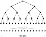
- the path diagram as shown in Figure 2, each layer represents 1 decoding bit. If the decoding result is 0, the path is developed along the left subtree. If the decoding result is 1, the path along the right subtree is developed.
- the L paths with the best path metric (PM) value are selected to be saved and the path is further developed to decode subsequent decoding bits.
- the PM values of the L paths are sorted from small to large, and the correct path is selected by the PM value and the Cyclic Redundancy Check (CRC). Until the last bit is translated, the PM is used to judge the quality of the path, and the PM is calculated by the LLR.
- CRC Cyclic Redundancy Check
- the number of decoding bits is very large, and the SCL decoding algorithm is used. Although the decoding performance is good, the defect of one decoding bit existing in the SC algorithm is diffused to the subsequent decoding bits.
- all the paths are sorted according to the PM value once, and the computational complexity and the sorting complexity are high.
- the present application provides a decoding method and device, and a decoder, which can perform parallel decoding based on path priority, and achieves lower computational complexity of Polar code decoding while ensuring better decoding performance.
- the present application provides a decoding method, including: after receiving N log likelihood ratio LLRs corresponding to signals to be decoded, N is a code length, and first, according to a priori LLR and/or a posteriori LLR, K The decoded bits are divided into reliable bits and unreliable bits.
- the a priori LLR is the average LLR of the decoded bits obtained according to the channel statistics
- the a posteriori LLR is the LLR of the decoded bits calculated in real time according to the N LLRs, and then according to N
- the LLR and the preset rule generate M decoding paths, 1 ⁇ M ⁇ Q, Q is the total number of preset decoding paths, and the total number of paths of each level does not exceed L, and L is preset to reach the same length.
- the total number of decoding paths, L ⁇ Q the default rule is: the next-level path of the reliable bit is 1, and the next-level path of the unreliable bit is 2, for a decoding path with a path length j
- K is the number of final decoding bits, wherein N, M, Q, L, K, and j are positive integers. , 1 ⁇ j ⁇ N, and then screen each target decoding channel according to the path metric PM value of the M decoding paths Obtaining the decoding result of each level of decoding bits.
- the decoding fails. Since the decoded bits are divided before the decoding path is generated and/or the decoding path is generated, the reliable bits are not split, and the unreliable bits are split, thereby reducing the number of path splits, thereby reducing the decoding path. The total number, thus reducing the number of paths for which the PM value is to be calculated and the number of paths participating in the sorting, reduces computational complexity and sorting complexity, and also ensures better decoding performance.
- the decoding bit in the present application may be an information bit, or may be an information bit and a fixed bit.
- the decoding bit is an information bit and a fixed bit
- the reliable bit and the unreliable bit are divided, Since the decoding result of the fixed bits is determined, no matter how many decoding results of the LLR are 0, the fixed bits can be directly divided into reliable bits, and the fixed bits do not affect the overall computational complexity.
- the method further includes: selecting one decoding path with the smallest PM value from the M decoding paths, and developing in parallel.
- Strip decoding path 1 ⁇ l ⁇ L.
- the correct decoding result can be found as soon as possible and the decoding can be ended to save decoding delay and complexity.
- the decoding delay can be reduced while reducing the computational complexity and ordering complexity while ensuring good decoding performance.
- the K decoding bits are divided into reliable bits and unreliable bits according to the a priori LLR and/or the a posteriori LLR, specifically, the reliable bits and the unreliable bits are divided according to the following rules:
- LLR prior (j) is a priori LLR
- LLR post (j) is a posteriori LLR
- C is preset parameters
- j is the jth bit, 1 ⁇ j ⁇ N.
- generating M decoding paths according to N LLRs and preset rules including: calculating LLRs of each level of decoding bits in each decoding path according to N LLRs, and according to each The LLR of the level decoding bit calculates the PM value of the corresponding decoding path, and generates a decoding path according to a preset rule.
- the M decoding paths with the smallest PM value are selected, and The M decoding paths are sorted in order of PM values from small to large.
- the LLR of each decoding bit in each decoding path is calculated in real time according to the N LLRs, and the PM value of the corresponding decoding path is calculated according to the LLR of each decoding bit, Calculate the PM value of each decoding path according to the following formula:
- z(j) is the decision value of the jth bit, and its value is 0 or 1.
- f(x) is the probability density function of x
- the PM value of the decoding path corresponding to the j-th decoding bit, for The mean value is negated.
- the path metric proposed in this application not only includes posterior information, but also considers a priori information, so as to more accurately reflect the path pros and cons, thus speeding up the time to find the best path.
- the method before each target decoding path is filtered according to the path metric PM value of the M decoding paths, the method further includes: decoding the M decoding paths according to the sorting condition and the PM value from small to large. Sorting, the sorting condition is: only the currently split path is sorted, and the non-split path does not participate in the sorting.
- the path management is initiated, and the shorter path is preferentially developed until the difference between the length of the largest decoding path and the length of the smallest decoding path in all decoding paths is less than or equal to a preset threshold.
- the method further includes: cutting off at least one decoding path in which the PM value in the M decoding paths is greater than a preset value, and the preset value is obtained by offline calculation or online calculation.
- the default values are: Where B is the preset parameter.
- the best decoding result can be found by updating the PM value and retaining the best several paths and phasing out the worst path. Therefore, better decoding performance can be ensured by the above path management and pruning processing.
- the a priori LLR is calculated according to the following formula:
- LLR prior (j) is a priori LLR.
- the decoding method of the present application can be implemented by pseudo code of the following example:
- the length queue is a decoding path queue, that is, a queue composed of multiple decoding paths.
- the application provides a decoding device, including:
- a receiving module configured to receive N log likelihood ratio LLRs corresponding to signals to be decoded, where N is a code length
- a dividing module configured to divide K decoding bits into reliable according to a priori LLR and/or a posteriori LLR Bit and unreliable bits
- the a priori LLR is the average LLR of the decoded bits obtained according to the channel statistics
- the a posteriori LLR is the LLR of the decoded bits calculated in real time according to the N LLRs
- a generating module is used for the N LLRs and
- the preset rule generates M decoding paths, 1 ⁇ M ⁇ Q
- Q is the total number of preset decoding paths, and the total number of paths of each level does not exceed L
- L is a preset decoding path that reaches the same length.
- the total number, L ⁇ Q the default rule is: the next level path of the reliable bit is 1, the next level path of the unreliable bit is 2, and the decoding path of a path length j is from 1st to j.
- the decoding result of the decoding bits is composed.
- Each decision result corresponds to one level of the decoding path, and K is the number of final decoding bits, wherein N, M, Q, L, K, and j are positive integers, 1 ⁇ j ⁇ N, a selection module for filtering each stage of the target decoding path according to the path metric PM value of the M decoding paths
- the verification module is configured to perform a cyclic redundancy check CRC on the K decoding bits in the first decoding path when the length of the first decoding path reaches N, and return the decoding if the CRC passes Successful; otherwise, continue to CRC the K decoding bits in the next decoding path of length N, if the result of CRC for all K decoding bits in the decoding path of length N is not passed, Then the decoding fails.
- the generating module generates M decoding paths according to the N LLRs and the preset rule, and is also used to: select one decoding path with the smallest PM value from the M decoding paths. Develop one decoding path in parallel, 1 ⁇ l ⁇ L.
- the partitioning module is specifically configured to divide the reliable bits and the unreliable bits according to the following rules:
- LLR prior (j) is a priori LLR
- LLR post (j) is a posteriori LLR
- C is preset parameters
- j is the jth bit, 1 ⁇ j ⁇ N.
- the generating module is specifically configured to: calculate LLRs of each level of decoding bits in each decoding path according to N LLRs, and calculate corresponding decoding according to LLRs of each level of decoding bits.
- the PM value of the path is generated according to a preset rule. When the total number of generated decoding paths is greater than Q, the M decoding paths with the smallest PM value are selected, and the M values are in the order of PM values from small to large.
- the decoding path is sorted.
- the generation module is specifically configured to calculate the PM value of each decoding path according to the following formula:
- z(j) is the decision value of the jth bit, and its value is 0 or 1.
- f(x) is the probability density function of x
- the PM value of the decoding path corresponding to the j-th decoding bit, for The mean value is negated.
- the selection module is further configured to: before the filtering of each level of the target decoding path according to the path metric PM value of the M decoding paths, according to the ordering condition and the PM value from small to large
- the stripping path is sorted by the following conditions: only the currently split path is sorted, and the non-split path does not participate in sorting.
- it also includes:
- the method further includes: a pruning module, configured to: cut off at least one decoding path whose PM value is greater than a preset value in the M decoding paths, and the preset value is obtained by offline calculation or online calculation.
- a pruning module configured to: cut off at least one decoding path whose PM value is greater than a preset value in the M decoding paths, and the preset value is obtained by offline calculation or online calculation.
- the default values are: Where B is the preset parameter.
- the a priori LLR is calculated according to the following formula:
- LLR prior (j) is a priori LLR.
- the present application provides a decoder, including: a receiver, configured to receive N log likelihood ratio LLRs corresponding to signals to be decoded, N is a code length, and a memory is configured to store program instructions and LLRs. Table, partial sum, decoding result, and decoding path queue and path metric PM value queue, part and an input for the G function, a processor for controlling program instruction execution, and the processor is configured to: according to a priori LLR and/or The a posteriori LLR divides the K decoded bits into reliable bits and unreliable bits.
- the a priori LLR is the average LLR of the decoded bits obtained according to the channel statistics
- the a posteriori LLR is the decoded bits calculated in real time according to the N LLRs.
- LLR generates M decoding paths according to N LLRs and preset rules, 1 ⁇ M ⁇ Q
- Q is the total number of preset decoding paths, and the total number of paths of each level does not exceed L
- L is preset
- the default rule is: the next-level path of the reliable bit is 1, and the next-level path of the unreliable bit is 2, for the translation of a path length j
- the code path consists of the decision result of the 1st to jth decoded bits, each The result of the second decision corresponds to the first level of the decoding path, and K is the number of final decoding bits, where N, M, Q, L, K, and j are positive integers, 1 ⁇ j ⁇ N, according to
- the verifier is used to determine the first line when the length of the first decoding path reaches N.
- the K decoding bits in the decoding path perform a cyclic redundancy check CRC. If the CRC passes, the decoding is successful; otherwise, the K decoding bits in the next decoding path of length N are continued to be CRC. If the result of CRC for all K decoding bits in the decoding path whose length reaches N is not passed, the decoding failure is returned.
- the processor generates M decoding paths according to the N LLRs and the preset rule, and is also used to: select one decoding path with the smallest PM value from the M decoding paths;
- the decoder further comprises: a parallel calculator for developing one decoding path in parallel, 1 ⁇ 1 ⁇ L; an input buffer for storing the decoding path selected from the decoding path queue; and an output buffer for A decoding path that calculates the calculated PM value.
- the processor is specifically configured to divide the reliable bits and the unreliable bits according to the following rules:
- LLR prior (j) is a priori LLR
- LLR post (j) is a posteriori LLR
- C is preset parameters
- j is the jth bit, 1 ⁇ j ⁇ N.
- the processor is specifically configured to: calculate, according to the N LLRs, the LLR of each level of the decoding bits in each coding path, and calculate the corresponding decoding according to the LLR of each level of the decoding bits.
- the PM value of the path is generated according to a preset rule. When the total number of generated decoding paths is greater than Q, the M decoding paths with the smallest PM value are selected, and the M values are in the order of PM values from small to large.
- the decoding path is sorted.
- the processor is specifically configured to calculate the PM value of each decoding path according to the following formula:
- z(j) is the decision value of the jth bit, and its value is 0 or 1.
- f(x) is the probability density function of x
- the PM value of the decoding path corresponding to the j-th decoding bit, for The mean value is negated.
- the processor is further configured to: before the filtering of each level of the target decoding path according to the path metric PM value of the M decoding paths, according to the ordering condition and the PM value from the smallest to the largest order
- the decoding path is sorted, and the sorting condition is: only the currently split path is sorted, and the non-split path does not participate in the sorting.
- it also includes:
- the method further includes: a pruning controller, configured to cut off at least one decoding path whose PM value is greater than a preset value in the M decoding paths, and the preset value is obtained by offline calculation or online calculation.
- the default value is Where B is the preset parameter.
- the a priori LLR is calculated according to the following formula:
- LLR prior (j) is a priori LLR.
- the application provides a storage medium, including: a readable storage medium and a computer program, the computer program A decoding method for implementing the various aspects of the first aspect and the first aspect described above.
- the present application provides a program product comprising a computer program (ie, an execution instruction) stored in a readable storage medium.
- a computer program ie, an execution instruction
- At least one processor of the decoding device or decoder may read the computer program from a readable storage medium, the at least one processor executing the computer program causing the decoding device or decoder to implement the first aspect and the first aspect Possible coding methods provided by the design.
- 1 is a schematic diagram of a SC decoding calculation process
- FIG. 2 is a schematic diagram of a decoding path in an SCL algorithm
- Embodiment 3 is a flowchart of Embodiment 1 of a decoding method of the present application.
- Embodiment 4 is a flowchart of Embodiment 2 of a decoding method provided by the present application.
- FIG. 5 is a flowchart of Embodiment 3 of a decoding method of the present application.
- Figure 6 is a parallel computing framework diagram of the embodiment shown in Figure 5;
- FIG. 7 is a schematic structural diagram of Embodiment 1 of a decoding device according to the present application.
- FIG. 8 is a schematic structural diagram of Embodiment 2 of a decoding device according to the present application.
- Embodiment 9 is a schematic structural diagram of Embodiment 1 of a decoder according to the present application.
- FIG. 10 is a schematic structural diagram of Embodiment 2 of a decoder according to the present application.
- the decoding of the Polar code is performed by the receiving end.
- the decoding method provided by the present application mainly involves the decoding process of the Polar code.
- SC and SCL the SC algorithm is a bit-by-bit decision, and all the commands are sequentially decoded.
- the decoding bit because the result of the previous decoding bit is used as an input for the subsequent decoding bit calculation, therefore, once the previous decoding bit is judged incorrectly, the error result will be used as the input of the subsequent bit G function, resulting in error diffusion. There is no chance to recover, so the decoding performance is not high.
- the SCL algorithm avoids this problem, the number of decoding bits is very large in practical applications.
- the SCL algorithm calculates the PM value of all paths, and sorts all paths according to the PM value for each decoding bit. , its computational complexity and sorting complexity are very high.
- the present application provides a decoding method, which can perform parallel decoding based on path priority, and achieves lower computational complexity of Polar code decoding while ensuring better decoding performance.
- the decoding method, device and decoder provided by the present application are described in detail below with reference to the accompanying drawings.
- the decoding method provided by the present application is mainly applied to various wireless communication systems, which can be implemented by software or hardware on the base station side/terminal side, in particular, including Enhanced Mobile Broadband (eMBB) in 5G, and ultra low.
- eMBB Enhanced Mobile Broadband
- uRLLC Ultra-reliable and low-latency communications
- mMTC Massive Machine-Type Communications
- the network element involved in the present application is mainly a base station and a terminal, and implements communication between the base station and the terminal.
- FIG. 3 is a flowchart of Embodiment 1 of the decoding method of the present application. As shown in FIG. 3, the method in this embodiment may include:
- the signal value, var is the noise variance.
- the K decoding bits are divided into reliable bits and unreliable bits according to the a priori LLR and/or the a posteriori LLR.
- the reliability of each decoded bit is measured according to a priori LLR and/or a posteriori LLR to determine whether to split the path of the bit, wherein the a priori LLR is the average LLR of the decoded bits obtained according to the channel statistics. It can be obtained by offline methods such as Gaussian approximation, polarization weight, Monte Carlo simulation, etc., or can be obtained by an online method of real-time statistics of the decoder.
- the a posteriori LLR is the LLR of the decoding bits calculated in real time according to the N LLRs, that is, the LLRs of the corresponding decoding bits obtained when the decoder performs real-time decoding.
- a priori LLR LLR prior (j) can be calculated according to the following formula:
- K decoding bits can be divided into reliable bits according to a priori LLR.
- the unreliable bit for example, the percentage of the reliable bit and the unreliable bit may be set according to the reliability of the information bit at the time of encoding or the polarization weight, and the threshold of the a priori LLR is set according to the percentage, and if the threshold is greater than the threshold, the bit is divided into a reliable bit, which is smaller than the The threshold is divided into unreliable bits.
- the next-level path of the reliable bit is highly deterministic, that is, the next-level path is one, and the next-level path of the unreliable path is two.
- reliable bits and unreliable bits can be divided according to the following rules:
- ⁇ is a preset parameter.
- the K decoded bits into reliable bits and unreliable bits according to the a posteriori LLR before generating the decoding path, for example, the information bit LLR obtained by approximating the "a posteriori LLR" obtained by decoding with a Gaussian approximation.
- the expectation is compared, and the K decoded bits are divided into reliable bits and unreliable bits in real time, for example, the reliable bits and the unreliable bits can be divided according to the following rules:
- ⁇ is a preset parameter.
- reliable bits and unreliable bits can be divided according to the following rules:
- C, ⁇ and ⁇ are preset parameters
- j is the jth bit, 1 ⁇ j ⁇ N.
- the decoding bit in the present application may be an information bit, or may be an information bit and a fixed bit.
- the decoding bit is an information bit and a fixed bit
- the reliable bit and the unreliable bit are divided, Since the decoding result of the fixed bits is determined, no matter how many decoding results of the LLR are 0, the fixed bits can be directly divided into reliable bits, and the fixed bits do not affect the overall computational complexity.
- L is a preset total number of decoding paths that reach the same length.
- L ⁇ Q the default rule is: the next level path of the reliable bit is 1, The next-level path of the unreliable bit is two.
- N, M, Q, L, and K are positive integers, 1 ⁇ j ⁇ N.
- the code length is N, and the code rate is K/N.
- S103 is specifically: firstly, the LLR of each decoding bit in each decoding path is calculated in real time according to the N LLRs, and the PM value of the corresponding decoding path is calculated according to the LLR of each decoding bit. Specifically, the PM value of each decoding path is calculated according to the following formula:
- z(j) is the decision value of the jth bit, and its value is 0 or 1.
- f(x) is the probability density function of x
- the PM value of the decoding path corresponding to the j-th decoding bit, for The mean value is negated.
- the decoding path is generated according to a preset rule.
- the M decoding paths with the smallest PM value are selected, and the M decoding paths are sequentially performed according to the PM value from small to large. Sort.
- the PM value of the decoding algorithm only considers the a posteriori LLR, but does not consider the a priori LLR. In the case of different path lengths, it may lead to unfairness between the long and short paths. Therefore, the path metric proposed by the present application not only includes the posterior information, but also considers the prior information, so as to more accurately reflect the advantages and disadvantages of the path, thereby accelerating the time to find the best path.
- the PM value defined above not only the number of paths Q to be stored is greatly reduced, but also the time required to search for the correct path is reduced.
- S104 Filter each stage of the target decoding path according to the PM values of the M decoding paths, and obtain a decoding result of each level of decoding bits.
- the decoding path with the smallest PM value in the M decoding paths is selected as the target decoding path, and the decoding result of each level of decoding bits is obtained, because the decoding path corresponding to each level of decoding bits Different lengths, for example, the decoding result of the second-level decoding bit is obtained.
- the decoding path with the smallest PM value in the three-level decoding path is re-screened, according to the screening. The resulting decoding path yields a decoding result of the third level of decoding bits.
- the decoding method provided in this embodiment after receiving the N LLRs corresponding to the to-be-decoded signal, firstly, according to the a priori LLR and/or the a posteriori LLR, the K decoding bits are divided into reliable bits and unreliable bits, and then When the M decoding paths are generated according to the N LLRs, the next-order path according to the reliable bits is one, and the next-level path of the unreliable bits is two rules to generate a decoding path, and then according to the M decoding paths.
- the PM value filters out each stage of the target decoding path, and obtains the decoding result of each level of decoding bits.
- the CRC is cyclically executed until the decoding is successful or decoded.
- the decoding is completed. Since the decoded bits are divided before the decoding path is generated and/or the decoding path is generated, the reliable bits are not split, and the unreliable bits are split, thereby reducing the number of path splits. , thereby reducing the total number of decoding paths, Therefore, the number of paths for calculating the PM value and the number of paths participating in the sorting are reduced, the computational complexity and the sorting complexity are reduced, and good decoding performance is also ensured.
- FIG. 4 is a flowchart of Embodiment 2 of the decoding method provided by the present application, as shown in FIG. 4, before S104 in Embodiment 1 shown in FIG. Can also include:
- S106 Sort the M decoding paths according to the sorting condition and the PM value from small to large.
- the sorting condition is: sorting only the currently split paths, and the non-split paths do not participate in the sorting.
- the sorting complexity can be further reduced, the time required for decoding can be reduced, and the decoding delay can be reduced.
- the difference from the length of the smallest decoding path is less than or equal to a preset threshold.
- the length difference between the long and short paths is large. After the PM value defined in this application is used, the correct path may still be eliminated. Therefore, before the path is eliminated, the length difference between the length paths must not be too large. The decoding performance can be further improved.
- the method may further include:
- the at least one decoding path whose PM value is greater than the preset value in the M decoding paths is clipped, and the preset value is obtained by offline calculation or online calculation.
- the preset value is obtained by offline calculation or online calculation.
- it can be initialized to the maximum value and updated by counting the maximum PM value of the correct decoding path.
- the default value can be:
- K is the number of decoding bits (if CRC bits are included, it should be counted), which is the total number of decoding paths up to the same length.
- B is a preset parameter and is a constant, which can be set to 3.
- the difference in PM values between paths will be larger, at this time by comparison and most The PM value of the good path, minus the poor path can reduce the complexity.
- the medium-to-noise ratio usually referred to as the SNR interval corresponding to 10 -3 ⁇ BLER ⁇ 0.5 ⁇ 10 -1
- the difference in PM values between paths is not too large, so the path management can control the longest and shortest paths. Differences to ensure a fair comparison and elimination of paths.
- the PM values of almost all paths are very poor.
- the PM value should be compared with a preset threshold, and all the cuts should be larger than The path to the threshold.
- the PM value plays a role in evaluating the path in the Polar code decoding. Generally, the lower the PM value, the more likely the path is the correct path, that is, the better the path. In the decoding process, the best decoding result can be found by updating the PM value and retaining the best several paths and phasing out the worst path. Therefore, better decoding performance can be ensured by the above path management and pruning processing.
- FIG. 5 is a flowchart of Embodiment 3 of the decoding method of the present application. As shown in FIG. 5, the method in this embodiment is based on FIG. 3 or FIG. 4, and in S103, M translations are generated according to N LLRs and preset rules.
- the code path can also include:
- One decoding path with the smallest PM value is selected from the M decoding paths, and one decoding path is developed in parallel, 1 ⁇ l ⁇ L. That is,
- S103' generates M decoding paths according to N LLRs and preset rules, selects one decoding path with the smallest PM value from the M decoding paths, and develops one decoding path in parallel, 1 ⁇ l ⁇ L .
- . l can be called parallelism, 1 ⁇ l ⁇ L.
- SCS Successive Cancellation Stack
- the path splitting rate is low, meaning that one path is almost independent, similar to one parallel SC decoder, and the calculation speed can be reached. very high.
- the queue operation caused by it ie, the development of two new paths
- the actual degree of parallelism is very high.
- the decoding algorithm provided in this embodiment can find the correct decoding result and end the decoding as soon as possible by preferentially expanding the optimal path, so as to save the decoding delay and complexity.
- the decoding delay can be reduced while reducing the computational complexity and ordering complexity while ensuring good decoding performance.
- Figure 6 is a diagram of the parallel computing framework of the embodiment shown in Figure 5, as shown in Figure 6, when the specific software or hardware is implemented, specifically:
- the principle of priority queue operation use a Q-length decoding path queue to store Q path information (PM value, path length), and preferentially select the best l decoding path from the queue, as shown in Figure 6. 8 is sent to the path buffer (Buf); 1 parallel computing unit (PE) is responsible for path processing of the filtered best path, that is, bit-by-bit decoding, and only inserts the path into the queue when the path is split. Operation: The newly generated two paths (path 0 and path 1) are inserted into the decoding path queue as shown in FIG. 6.
- l-parallel computing architecture Partially parallel computing of the decoding tree with width L, that is, selecting one of the best paths from the queue to process at the same time, l is called parallelism, and 1 ⁇ l ⁇ L.
- l-storage architecture only store the LLR table (stored in RAM) of l decoding paths in the current parallel computing unit processing, so that the number of LLR tables is l ⁇ L.
- LLR table stored in RAM
- LLR table of the new decoding path is not saved, some LLR values need to be recalculated, but since the two LLR tables usually contain higher redundancy, The recalculated LLR values are generally not too large. In practice, only the extra LLR values between the two decoding paths need to be additionally calculated.
- decoding method of the present application can be implemented by pseudo code of the following example:
- the length queue is a decoding path queue, that is, a queue composed of multiple decoding paths.
- FIG. 7 is a schematic structural diagram of Embodiment 1 of a decoding device of the present application.
- the decoding device of this embodiment may include: a receiving module 11, a dividing module 12, a generating module 13, a selecting module 14, and a verifying module. 15.
- the receiving module 11 is configured to receive N log likelihood ratio LLRs corresponding to the signals to be decoded, where N is a code length.
- the dividing module 12 is configured to divide the K decoding bits into reliable bits and unreliable bits according to the a priori LLR and/or the a posteriori LLR, and the a priori LLR is the average LLR of the decoding bits obtained according to the channel statistical information, and the a posteriori LLR The LLR of the decoded bits calculated in real time from the N LLRs.
- the generating module 13 is configured to generate M decoding paths according to the N LLRs and preset rules, where 1 ⁇ M ⁇ Q, where Q is the total number of preset decoding paths, and the total number of paths of each level does not exceed L, L is The total number of decoding paths that reach the same length, L ⁇ Q, the default rule is: the next-level path of the reliable bit is 1, and the next-level path of the unreliable bit is 2, for one path length
- the decoding path of j is composed of the decision results of the first to j decoding bits, each decision result corresponds to one level of the decoding path, and K is the number of final decoding bits, where N, M, Q, L, K is a positive integer, 1 ⁇ j ⁇ N.
- the selecting module 14 is configured to filter out each stage of the target decoding path according to the path metric PM value of the M decoding paths, and obtain the decoding result of each level of decoding bits.
- the verification module 15 is configured to perform a cyclic redundancy check CRC on the K decoding bits in the first decoding path when the length of the first decoding path reaches N, and return the translation if the CRC passes. The code succeeds; otherwise, the CRC of the K decoding bits in the next decoding path of length N is continued, and the result of CRC for all K decoding bits in the decoding path of length N is not passed. , then return decoding failed.
- the dividing module 12 is specifically configured to divide the reliable bits and the unreliable bits according to the following rules:
- LLR prior (j) is a priori LLR
- LLR post (j) is a posteriori LLR
- C is preset parameters
- j is the jth bit, 1 ⁇ j ⁇ N.
- the a priori LLR is calculated according to the following formula:
- LLR prior (j) is a priori LLR.
- the generating module 13 is specifically configured to: calculate, according to the N LLRs, the LLRs of the decoding bits of each of the decoding paths in real time, and calculate the PM of the corresponding decoding path according to the LLRs of the decoding bits of each level. value.
- the decoding path is generated according to a preset rule. When the total number of generated decoding paths is greater than Q, the M decoding paths with the smallest PM value are selected, and the M decoding paths are sorted according to the PM value from small to large. .
- the generating module 13 is specifically configured to calculate the PM value of each decoding path according to the following formula:
- z(j) is the decision value of the jth bit, and its value is 0 or 1.
- f(x) is the probability density function of x
- the PM value of the decoding path corresponding to the j-th decoding bit, for The mean value is negated.
- the selecting module 14 is further configured to: before the filtering of each target decoding path according to the path metric PM value of the M decoding paths, decode the M strips according to the sorting condition and the PM value from small to large.
- the path is sorted.
- the sorting condition is: only the currently split path is sorted, and the non-split path does not participate in the sort.
- the decoding device of this embodiment may be used to implement the technical solution of the method embodiment shown in FIG. 3 or FIG. 4, and the implementation principle is similar, and details are not described herein again.
- the decoding device after receiving the N LLRs corresponding to the signal to be decoded, firstly divides K decoding bits into reliable bits and unreliable bits according to a priori LLR and/or a posteriori LLR, and then When the M decoding paths are generated according to the N LLRs, the next-order path according to the reliable bits is one, and the next-level path of the unreliable bits is two rules to generate a decoding path, and then according to the M decoding paths.
- the PM value filters out each stage of the target decoding path, and obtains the decoding result of each level of decoding bits. Finally, when a length of a decoding path reaches N, the CRC is cyclically executed until the decoding is successful or decoded.
- the decoding is completed. Since the decoded bits are divided before the decoding path is generated and/or the decoding path is generated, the reliable bits are not split, and the unreliable bits are split, thereby reducing the number of path splits. Therefore, the total number of decoding paths is reduced, thereby reducing the number of paths for which the PM value is to be calculated and the number of paths participating in the sorting, which reduces computational complexity and sorting complexity, and also ensures better decoding. can.
- the generating module 13 generates M decoding paths according to the N LLRs and the preset rule, and is also used to: select the PM from the M decoding paths.
- the l decoding path with the smallest value develops one decoding path in parallel, 1 ⁇ l ⁇ L.
- the decoding device of this embodiment may be used to implement the technical solution of the method embodiment shown in FIG. 5, and the implementation principle thereof is similar, and details are not described herein again.
- the decoding device provided in this embodiment can find the correct decoding result and end the decoding as soon as possible by preferentially expanding the optimal path, thereby saving the decoding delay and complexity. Compared with the SCL algorithm, the decoding delay can be reduced while reducing the computational complexity and ordering complexity while ensuring good decoding performance.
- FIG. 8 is a schematic structural diagram of Embodiment 2 of the decoding device of the present application.
- the decoding device of the present embodiment further includes: a path management module 16 based on the device structure shown in FIG. 7 .
- the method further includes: a pruning module 17 configured to cut off at least one decoding path in which the PM value in the M decoding paths is greater than a preset value, where the preset value is obtained by offline calculation or online calculation.
- the preset value can be:
- the decoding apparatus provided in this embodiment can find the best decoding result by updating the PM value and retaining the optimal number of paths and eliminating the worst path in the decoding process. Therefore, better decoding performance can be ensured by the above path management and pruning processing.
- the decoder of this embodiment may include: a receiver 21, a memory 22, a processor 23 for controlling execution of program instructions, and an inspection.
- the receiver 21 is configured to receive N log likelihood ratio LLRs corresponding to the signals to be decoded, where N is a code length.
- the memory 22 is used to store program instructions, LLR tables, partial sums, decoding results, and decoding path queues and PM value queues, part of which is an input to the G function.
- the processor 23 is configured to: divide the K decoding bits into reliable bits and unreliable bits according to the a priori LLR and/or the a posteriori LLR, and the a priori LLR is the average LLR of the decoded bits obtained according to the channel statistics, and the posterior The LLR is the LLR of the decoded bits calculated in real time from the N LLRs.
- N LLRs and preset rules 1 ⁇ M ⁇ Q
- Q is the total number of preset decoding paths, the total number of paths of each level does not exceed L
- L is preset to reach the same
- the total number of decoding paths of length, L ⁇ Q the default rule is: one path of the next level of reliable bits, and two paths of the next level of unreliable bits, for a decoding path with a path length j It consists of the decision results of the 1st to jth decoded bits. Each decision result corresponds to the level of the decoding path, and K is the number of final decoded bits, where N, M, Q, L, and K are positive integers. , 1 ⁇ j ⁇ N.
- Each stage of the target decoding path is filtered according to the path metric PM value of the M decoding paths, and the decoding result of each level of decoding bits is obtained.
- the verifier 24 is configured to perform a cyclic redundancy check CRC on the K decoding bits in the first decoding path when the length of the first decoding path reaches N, and return the decoding if the CRC passes. Successful; otherwise, continue to CRC the K decoding bits in the next decoding path of length N, if the result of CRC for all K decoding bits in the decoding path of length N is not passed, Then the decoding fails.
- the a priori LLR is calculated according to the following formula:
- LLR prior (j) is a priori LLR.
- the decoding device after receiving the N LLRs corresponding to the signal to be decoded, firstly divides K decoding bits into reliable bits and unreliable bits according to a priori LLR and/or a posteriori LLR, and then When the M decoding paths are generated according to the N LLRs, the next-order path according to the reliable bits is one, and the next-level path of the unreliable bits is two rules to generate a decoding path, and then according to the M decoding paths. The PM value is filtered out for each level of the target decoding path, and the translation of each level of decoding bits is obtained.
- the CRC is cyclically performed until the result of decoding success or decoding failure is obtained, and the decoding is completed, because the decoding path is generated before and/or the decoding path is generated.
- the decoded bits are divided, the reliable bits are not split, and the unreliable bits are split, thus reducing the number of path splits, thereby reducing the total number of decoding paths, thus reducing the number of paths for which the PM value is to be calculated and participating.
- the number of sorted paths reduces computational complexity and sorting complexity, while also ensuring better decoding performance.
- FIG. 10 is a schematic structural diagram of Embodiment 2 of the decoder of the present application.
- the decoder of this embodiment may further include: a parallel calculator 25, input on the basis of the decoder shown in FIG.
- the cache 26 and the output buffer 27 need to be explained.
- the operations performed by the processor 23 can be performed by the parallel calculator 25 and the split controller 30 in FIG. 10, and the parallel calculator 25 has one.
- the processor 23 generates M decoding paths according to the N LLRs and the preset rule, and is also used to: select one decoding path with the smallest PM value from the M decoding paths.
- the parallel calculator 25 is used to develop one decoding path in parallel, 1 ⁇ 1 ⁇ L, the input buffer 26 is used for storing the decoding path selected from the decoding path queue, and the output buffer 27 is used for storing the calculated PM value.
- Decoding path By preferentially extending the optimal path, the correct decoding result can be found as soon as possible and the decoding can be ended to save decoding delay and complexity. Compared with the SCL algorithm, the decoding delay can be reduced while reducing the computational complexity and ordering complexity while ensuring good decoding performance.
- processor 23 is specifically configured to:
- the reliable bits and unreliable bits are divided according to the following rules:
- LLR prior (j) is a priori LLR
- LLR post (j) is a posteriori LLR
- C is preset parameters
- j is the jth bit, 1 ⁇ j ⁇ N.
- the processor 23 is specifically configured to: calculate, according to the N LLRs, the LLRs of the decoding bits of each of the decoding paths in real time, and calculate the PM values of the corresponding decoding paths according to the LLRs of the decoding bits of each level.
- the decoding path is generated according to a preset rule. When the total number of generated decoding paths is greater than Q, the M decoding paths with the smallest PM value are selected, and the M decoding paths are performed according to the PM values from small to large. Sort.
- the processor 23 is specifically configured to calculate the PM value of each decoding path according to the following formula:
- z(j) is the decision value of the jth bit, and its value is 0 or 1.
- f(x) is the probability density function of x
- the PM value of the decoding path corresponding to the j-th decoding bit, for The mean value is negated.
- the processor 23 is further configured to decode the M strips according to the sorting condition and the PM value from small to large before filtering each level of the target decoding path according to the path metric PM value of the M decoding paths.
- the path is sorted.
- the sorting condition is: only the currently split path is sorted, and the non-split path does not participate in the sort.
- the path manager 28 and the pruning controller 29 are further included.
- the pruning controller 29 is configured to cut off at least one decoding path whose PM value is greater than a preset value in the M decoding paths, and the preset value is obtained by offline calculation or online calculation.
- the default value is:
- the decoding apparatus provided in this embodiment can find the best decoding result by updating the PM value and retaining the optimal number of paths and eliminating the worst path in the decoding process. Therefore, better decoding performance can be ensured by the above path management and pruning processing.
- a computer program and a memory may also be included, the computer program being stored in the memory, the processor running the computer program to perform the synchronization processing method described above.
- the number of processors is at least one, and is used to execute an execution instruction of the memory storage, that is, a computer program.
- the decoding method provided by the various embodiments of the foregoing aspects is performed by the terminal device and the network device performing data interaction through the communication interface.
- the memory may also be integrated in the processor.
- the present application also provides a storage medium comprising: a readable storage medium and a computer program for implementing a decoding method performed by a decoding device or a decoder.
- the application also provides a program product comprising a computer program (ie, an execution instruction) stored in a readable storage medium.
- a computer program ie, an execution instruction
- At least one processor of the decoding device or decoder can read the computer program from a readable storage medium, and the at least one processor executes the computer program such that the decoding device or decoder implements the translation provided by the various embodiments described above Code method.
- the aforementioned program can be stored in a computer readable storage medium.
- the program when executed, performs the steps including the foregoing method embodiments; and the foregoing storage medium includes various media that can store program codes, such as a ROM, a RAM, a magnetic disk, or an optical disk.
Landscapes
- Engineering & Computer Science (AREA)
- Physics & Mathematics (AREA)
- Probability & Statistics with Applications (AREA)
- Theoretical Computer Science (AREA)
- Computing Systems (AREA)
- Computer Networks & Wireless Communication (AREA)
- Signal Processing (AREA)
- Artificial Intelligence (AREA)
- Error Detection And Correction (AREA)
Abstract
一种译码方法及设备、译码器,该方法包括:接收待译码信号对应的N个LLR,N为码长(S101),根据先验LLR和/或后验LLR将K个译码比特划分为可靠比特和不可靠比特(S102),根据N个LLR和预设规则生成M条译码路径(S103),根据M条译码路径的PM值筛选出每一级目标译码路径,得到每一级译码比特的译码结果(S104)。
Description
本申请涉及编译码技术领域,尤其涉及一种译码方法及设备、译码器。
Polar(极化)码是一种理论上证明可以达到香农极限的编码方法。Polar码是一种线性块码,其编码过程为 其中
其中 是一个N长二进制的行矢量,BN为N×N的比特反转(Bit Reversal)矩阵,
 为log2N个矩阵F2的克罗内克(Kronecker)乘积,
 中的一部分比特用于信息传输,称为信息比特,余下的比特置为固定比特。Polar码在广泛的工作区间(码长、码率、信噪比)都具有极佳的译码性能。
现有的逐比特消除译码算法(Successive Cancellation,SC)的译码过程为:接收到信号后,逐个计算信息比特的对数似然比(Log Likelihood Ratio,LLR),若信息比特的LLR>0,则译码结果为0,若信息比特的LLR<0,则译码结果为1,固定比特无论LLR为多少译码结果都置为0。图1为SC译码计算过程示意图,以译码比特为4个为例,图1中共有8个计算节点,其中有4个F节点,4个G节点,F节点和G节点分别对应F函数和G函数。F节点的计算需要其右侧2项LLR输入,G节点的计算需要其右侧2项LLR输入以及上一级的输出也作为输入,只有输入项计算完成后,才能计算输出。按照上述计算规则,图1中从右侧接收信号开始,按序计算8个节点,获得的译码比特依次为①→②→③→④,至此译码完成。可以看出,SC算法为逐比特判决,一旦判错,其错误结果将作为后续比特G函数的输入,导致错误扩散,且没有机会挽回,因此译码性能不高。为解决这一问题,在逐次消除列表算法(Successive Cancellation List,SCL)中,SCL算法将0和1对应的译码结果都保存作为2个分支译码路径,图2为SCL算法中的译码路径示意图,如图2所示,每一层代表1个译码比特,若译码结果为0,则沿着左子树发展路径,若译码结果为1,则沿着右子树发展路径,当译码路径的总数超过预设的路径宽度L(一般L=2n)时,选择出路径度量(PM)值最佳的L条路径保存并继续发展路径以译出后续的译码比特,对于每一级的译码比特,对L条路径的PM值按照从小到大排序,并通过PM值和循环冗余码校验(Cyclic Redundancy Check,CRC)来筛选出正确的路径,如此反复,直到译完最后一个比特,其中的PM用于判断路径的好坏,PM通过LLR计算得出。
在实际应用中,译码比特的数目是非常大的,使用SCL译码算法,虽然译码性能较好,避免了SC算法中存在的一个译码比特出错会扩散到后续的译码比特的缺陷,但是要计算所有路径的PM值,对于每一个译码比特都要对所有路径根据PM值进行一次排序,其计算复杂度和排序复杂度都很高。
发明内容
本申请提供一种译码方法及设备、译码器,可基于路径优先级进行并行译码,实现了在保证较好的译码性能的同时降低Polar码译码的计算复杂度。
第一方面,本申请提供一种译码方法,包括:接收待译码信号对应的N个对数似然比LLR之后,N为码长,首先根据先验LLR和/或后验LLR将K个译码比特划分为可靠比特和不可靠比特,先验LLR为根据信道统计信息得到的译码比特的平均LLR,后验LLR为根据N个LLR实时计算的译码比特的LLR,接着根据N个LLR和预设规则生成M条译码路径,1≤M≤Q,Q为预设的译码路径的总数,每一级的路径的总数不超过L,L为预设的达到相同长度的译码路径的总数,L≤Q,预设规则为:可靠比特的下一级路径为1条,不可靠比特的下一级路径为2条,对于一条路径长度为j的译码路径由第1至j个译码比特的判决结果组成,每一次判决结果对应译码路径的一级,K为最终的译码比特的数目,其中N、M、Q、L、K、j均为正整数,1≤j≤N,接着根据M条译码路径的路径度量PM值筛选出每一级目标译码路径,得到每一级译码比特的译码结果,最后,当有第一条译码路径的长度达到N时,对第一条译码路径中的K个译码比特进行循环冗余码校验CRC,若CRC通过,则译码成功;否则继续对下一条长度达到N的译码路径中的K个译码比特进行CRC,若对所有的长度达到N的译码路径中的K个译码比特进行CRC的结果都未通过,则译码失败。由于在生成译码路径之前和/生成译码路径的同时对译码比特进行了划分,可靠的比特不分裂,不可靠的比特才分裂,因此减少了路径分裂次数,从而减少了译码路径的总数,因此降低了所要计算PM值的路径数目以及参与排序的路径数目,降低了计算复杂度和排序复杂度,同时也保证了较好的译码性能。
需要说明的是,本申请中的译码比特可以是信息比特,也可以是信息比特和固定比特,当译码比特为信息比特和固定比特时,在进行可靠比特与不可靠比特的划分时,因为固定比特的译码结果是确定的,无论LLR为多少译码结果都为0,因此可直接将固定比特划分为可靠比特,固定比特不影响总体的计算复杂度。
在一种可能的设计中,根据N个LLR和预设规则生成M条译码路径的同时,还包括:从M条译码路径中选择出PM值最小的l条译码路径,并行发展l条译码路径,1≤l≤L。
通过优先拓展最佳路径,可以尽快地找到正确译码结果并结束译码,以节省译码时延和复杂度。相比较SCL算法,在具有降低计算复杂度和排序复杂度,同时也保证了较好的译码性能的优点的同时,还可以降低译码时延。
在一种可能的设计中,根据先验LLR和/或后验LLR将K个译码比特划分为可靠比特和不可靠比特,具体为根据如下规则划分出可靠比特和不可靠比特:


其中,LLRprior(j)为先验LLR,LLRpost(j)为后验LLR,C、θ和η为预设参数,j为第j个比特,1≤j≤N。
在一种可能的设计中,根据N个LLR和预设规则生成M条译码路径,包括:根据N个LLR实时计算每条译码路径中每一级译码比特的LLR,并根据每一级译码比特的LLR计算相应的译码路径的PM值,按照预设规则生成译码路径,当生成的译码路径的总数大于Q时,选择出PM值最小的M条译码路径,并按照PM值从小到大的顺序对M条译码路径进行排序。
在一种可能的设计中,根据N个LLR实时计算每条译码路径中每一级译码比特的LLR,并根据每一级译码比特的LLR计算相应的译码路径的PM值,具体为根据如下公式计算每条译码路径的PM值:


其中, 为第j级译码比特对应的译码路径的PM值,
 为
为 的均值取反。
本申请提出的路径度量不仅包含后验信息,也将先验信息计入考虑,这样才能更加准确的反映路径优劣,从而加快找到最佳路径的时间。通过实验仿真,采用上述定义的PM值后,不仅所需存储的路径数Q大幅降低,搜索到正确路径所需的时间也有所降低。
在一种可能的设计中,根据M条译码路径的路径度量PM值筛选出每一级目标译码路径之前,还包括:根据排序条件和PM值从小到大的顺序对M条译码路径进行排序,排序条件为:只对当前分裂的路径进行排序,不分裂的路径不参与排序。通过上述插入排序的方法,可以进一步降低排序复杂度,减少译码所需的时间,降低译码时延。
在一种可能的设计中,当M=Q时,还包括:
启动路径管理,优先发展较短路径直到所有译码路径中最大的译码路径的长度与最小的译码路径的长度之差小于或等于预设阈值。
在一种可能的设计中,还包括:剪除M条译码路径中PM值大于预设值的至少一条译码路径,预设值通过离线计算或在线计算得到。
其中的预设值为: 其中,B是预设参数。
在译码过程中,通过更新PM值,并保留最佳的若干条路径、淘汰最差路径,可以找到最佳的译码结果。因此,通过上述路径管理和剪枝处理,可以保证较好的译码性能。
在一种可能的设计中,先验LLR根据如下公式计算得到:

其中,LLRprior(j)为先验LLR。
在一种可能的设计中,本申请的译码方法可通过以下示例的伪代码实现:
While M>0
If“M<Q”or“d<D”
从PM队列这pop最优路径
Else
从length队列中pop最短路径
End
更新路径长度(+1)
更新译码树在该比特的宽度
If w==L
检出所有更短的路径
End
利用PM值剪枝
If固定比特或先/后验可靠比特
不分裂路径,采用硬判决结果
Else
分裂路径,同时保留0/1对应的路径
End
If j==N and CRC校验通过
Return译码结果
Else
将当前路径删除
End
If“分裂”
将新产生的2条路径压入PM队列
将新产生的2条路径压入length队列
End
End
Return“译码失败”
其中,length队列为译码路径队列,即多条译码路径组成的队列。
第二方面,本申请提供一种译码设备,包括:
接收模块,用于接收待译码信号对应的N个对数似然比LLR,N为码长,划分模块,用于根据先验LLR和/或后验LLR将K个译码比特划分为可靠比特和不可靠比特,先验LLR为根据信道统计信息得到的译码比特的平均LLR,后验LLR为根据N个LLR实时计算的译码比特的LLR,生成模块,用于根据N个LLR和预设规则生成M条译码路径,1≤M≤Q,Q为预设的译码路径的总数,每一级的路径的总数不超过L,L为预设的达到相同长度的译码路径的总数,L≤Q,预设规则为:可靠比特的下一级路径为1条,不可靠比特的下一级路径为2条,对于一条路径长度为j的译码路径由第1至j个译码比特的判决结果组成,每一次判决结果对应译码路径的一级,K为最终的译码比特的数目,其中N、M、Q、L、K、j均为正整数,1≤j≤N,选择模块,用于根据M条译码路径的路径度量PM值筛选出每一级目标译码路径,得到每一级译码比特的译码结果,校
验模块,用于在有第一条译码路径的长度达到N时,对第一条译码路径中的K个译码比特进行循环冗余码校验CRC,若CRC通过,则返回译码成功;否则继续对下一条长度达到N的译码路径中的K个译码比特进行CRC,若对所有的长度达到N的译码路径中的K个译码比特进行CRC的结果都未通过,则返回译码失败。
在一种可能的设计中,生成模块根据N个LLR和预设规则生成M条译码路径的同时,还用于:从M条译码路径中选择出PM值最小的l条译码路径,并行发展l条译码路径,1≤l≤L。
在一种可能的设计中,划分模块具体用于根据如下规则划分出可靠比特和不可靠比特:


其中,LLRprior(j)为先验LLR,LLRpost(j)为后验LLR,C、θ和η为预设参数,j为第j个比特,1≤j≤N。
在一种可能的设计中,生成模块具体用于:根据N个LLR实时计算每条译码路径中每一级译码比特的LLR,并根据每一级译码比特的LLR计算相应的译码路径的PM值,按照预设规则生成译码路径,当生成的译码路径的总数大于Q时,选择出PM值最小的M条译码路径,并按照PM值从小到大的顺序对M条译码路径进行排序。
在一种可能的设计中,生成模块具体用于根据如下公式计算每条译码路径的PM值:


其中, 为第j级译码比特对应的译码路径的PM值,
 为
为 的均值取反。
在一种可能的设计中,选择模块还用于:在根据M条译码路径的路径度量PM值筛选出每一级目标译码路径之前,根据排序条件和PM值从小到大的顺序对M条译码路径进行排序,排序条件为:只对当前分裂的路径进行排序,不分裂的路径不参与排序。
在一种可能的设计中,还包括:
路径管理模块,用于在M=Q时,启动路径管理,优先发展较短路径直到所有译码路径中最大
的译码路径的长度与最小的译码路径的长度之差小于或等于预设阈值。
在一种可能的设计中,还包括:剪枝模块,用于剪除M条译码路径中PM值大于预设值的至少一条译码路径,预设值通过离线计算或在线计算得到。
其中的预设值为: 其中,B是预设参数。
在一种可能的设计中,先验LLR根据如下公式计算得到:

其中,LLRprior(j)为先验LLR。
上述第二方面以及上述第二方面的各可能的设计所提供的译码设备,其有益效果可以参见上述第一方面和第一方面的各可能的设计所带来的有益效果,在此不再赘述。
第三方面,本申请提供一种译码器,包括:接收器,用于接收待译码信号对应的N个对数似然比LLR,N为码长,存储器,用于存储程序指令、LLR表、部分和、译码结果以及译码路径队列和路径度量PM值队列,部分和为G函数的一个输入,用于控制程序指令执行的处理器,处理器用于:根据先验LLR和/或后验LLR将K个译码比特划分为可靠比特和不可靠比特,先验LLR为根据信道统计信息得到的译码比特的平均LLR,后验LLR为根据N个LLR实时计算的译码比特的LLR,根据N个LLR和预设规则生成M条译码路径,1≤M≤Q,Q为预设的译码路径的总数,每一级的路径的总数不超过L,L为预设的达到相同长度的译码路径的总数,L≤Q,预设规则为:可靠比特的下一级路径为1条,不可靠比特的下一级路径为2条,对于一条路径长度为j的译码路径由第1至j个译码比特的判决结果组成,每一次判决结果对应译码路径的一级,K为最终的译码比特的数目,其中N、M、Q、L、K、j均为正整数,1≤j≤N,根据M条译码路径的路径度量PM值筛选出每一级目标译码路径,得到每一级译码比特的译码结果,检验器,用于在有第一条译码路径的长度达到N时,对第一条译码路径中的K个译码比特进行循环冗余码校验CRC,若CRC通过,则返回译码成功;否则继续对下一条长度达到N的译码路径中的K个译码比特进行CRC,若对所有的长度达到N的译码路径中的K个译码比特进行CRC的结果都未通过,则返回译码失败。
在一种可能的设计中,处理器根据N个LLR和预设规则生成M条译码路径的同时,还用于:从M条译码路径中选择出PM值最小的l条译码路径;译码器还包括:并行计算器,用于并行发展l条译码路径,1≤l≤L;输入缓存,用于存储从译码路径队列中筛选出的译码路径;输出缓存,用于存储计算过PM值的译码路径。
在一种可能的设计中,处理器具体用于根据如下规则划分出可靠比特和不可靠比特:


其中,LLRprior(j)为先验LLR,LLRpost(j)为后验LLR,C、θ和η为预设参数,j为第j个比特,1≤j≤N。
在一种可能的设计中,处理器具体用于:根据N个LLR实时计算每条译码路径中每一级译码比特的LLR,并根据每一级译码比特的LLR计算相应的译码路径的PM值;按照预设规则生成译码路径,当生成的译码路径的总数大于Q时,选择出PM值最小的M条译码路径,并按照PM值从小到大的顺序对M条译码路径进行排序。
在一种可能的设计中,处理器具体用于根据如下公式计算每条译码路径的PM值:


其中, 为第j级译码比特对应的译码路径的PM值,
 为
为 的均值取反。
在一种可能的设计中,处理器还用于在根据M条译码路径的路径度量PM值筛选出每一级目标译码路径之前,根据排序条件和PM值从小到大的顺序对M条译码路径进行排序,排序条件为:只对当前分裂的路径进行排序,不分裂的路径不参与排序。
在一种可能的设计中,还包括:
路径管理器,用于在M=Q时,启动路径管理,优先发展较短路径直到所有译码路径中最大的译码路径的长度与最小的译码路径的长度之差小于或等于预设阈值。
在一种可能的设计中,还包括:剪枝控制器,用于剪除M条译码路径中PM值大于预设值的至少一条译码路径,预设值通过离线计算或在线计算得到。
其中的预设值为 其中,B是预设参数。
在一种可能的设计中,先验LLR根据如下公式计算得到:

其中,LLRprior(j)为先验LLR。
上述第三方面以及上述第三方面的各可能的设计所提供的译码器,其有益效果可以参见上述第一方面和第一方面的各可能的设计所带来的有益效果,在此不再赘述。
第四方面,本申请提供一种存储介质,包括:可读存储介质和计算机程序,所述计算机程序
用于实现上述第一方面和第一方面的各可能的设计所述的译码方法。
第五方面,本申请提供一种程序产品,该程序产品包括计算机程序(即执行指令),该计算机程序存储在可读存储介质中。译码设备或译码器的至少一个处理器可以从可读存储介质读取该计算机程序,至少一个处理器执行该计算机程序使得译码设备或译码器实施第一方面和第一方面的各可能的设计所提供的译码方法。
图1为SC译码计算过程示意图;
图2为SCL算法中的译码路径示意图;
图3为本申请译码方法实施例一的流程图;
图4为本申请提供的译码方法实施例二的流程图;
图5为本申请译码方法实施例三的流程图;
图6为图5所示的实施例的并行计算框架图;
图7为本申请译码设备实施例一的结构示意图;
图8为本申请译码设备实施例二的结构示意图;
图9为本申请译码器实施例一的结构示意图;
图10为本申请译码器实施例二的结构示意图。
Polar码的译码由接收端执行,本申请提供的译码方法主要涉及Polar码的译码过程,现有的译码算法SC和SCL中,SC算法为逐比特判决,按顺序依次译出所有的译码比特,由于前一个译码比特的结果作为后一个译码比特计算的一个输入,因此,一旦前一个译码比特判错,其错误结果将作为后续比特G函数的输入,导致错误扩散,且没有机会挽回,因此译码性能不高。SCL算法虽然避免了这一问题,但是实际应用中译码比特的数目是非常大的,SCL算法要计算所有路径的PM值,对于每一个译码比特都要对所有路径根据PM值进行一次排序,其计算复杂度和排序复杂度都很高。针对上述问题,本申请提供一种译码方法,可基于路径优先级进行并行译码,实现了在保证较好的译码性能的同时降低Polar码译码的计算复杂度。下面结合附图详细说明本申请提供的译码方法及设备、译码器。
本申请提供的译码方法主要应用于各种无线通信系统,其可以在基站侧/终端侧由软件或硬件实现,特别地,包括5G中的增强移动宽带(Enhanced Mobile Broadband,eMBB)、超低时延超高可靠通信(Ultra-reliable and low-latency communications,uRLLC)以及大规模机器通信(Massive Machine-Type Communications,mMTC)场景。
本申请涉及的网元主要是基站和终端,实现基站与终端之间的通信。
图3为本申请译码方法实施例一的流程图,如图3所示,本实施例的方法可以包括:
S101、接收待译码信号对应的N个LLR,N为码长。
具体地,接收端接收到待译码信号之后,通过计算得到待译码信号对应的N个LLR,送至接收端的译码器,其中LLR=2*y/var,y是待译码信号的信号值,var是噪声方差。
S102、根据先验LLR和/或后验LLR将K个译码比特划分为可靠比特和不可靠比特。
具体是根据先验LLR和/或后验LLR衡量每个译码比特的可靠度以决定是否对该比特进行路径的分裂,其中的先验LLR为根据信道统计信息得到的译码比特的平均LLR,其可由高斯近似、极化权重、蒙特卡洛仿真等离线方法得到,也可以由译码器实时统计的在线方法得到。后验LLR为根据N个LLR实时计算的译码比特的LLR,即译码器实时译码时获得的对应译码比特的LLR。
具体地,先验LLR LLRprior(j)可根据如下公式计算得到:

其中的K为要译出的译码比特的总数,译码器是在译码前就已获知的,在生成译码路径之前,可以是根据先验LLR将K个译码比特划分为可靠比特和不可靠比特,例如可根据编码时信息比特的可靠度或者极化权重设置可靠比特与不可靠比特的百分比,根据这个百分比设置先验LLR的阈值,大于该阈值则划分为可靠比特,小于该阈值则划分为不可靠比特,可靠比特的下一级路径确定性高,即下一级路径为1条,不可靠路径的下一级路径为2条。例如可以是根据如下规则划分出可靠比特和不可靠比特:
其中,θ为预设参数。
还可以是在生成译码路径之前根据后验LLR将K个译码比特划分为可靠比特和不可靠比特,例如是通过将译码时获得的“后验LLR”与高斯近似获得的信息比特LLR的期望进行比较,实时将K个译码比特划分为可靠比特和不可靠比特,例如可以是根据如下规则划分出可靠比特和不可靠比特:

其中,η为预设参数。
还可以是根据先验LLR和后验LLR将K个译码比特划分为可靠比特和不可靠比特。例如可以是根据如下规则划分出可靠比特和不可靠比特:

其中,C、θ和η为预设参数,j为第j个比特,1≤j≤N。
需要说明的是,本申请中的译码比特可以是信息比特,也可以是信息比特和固定比特,当译码比特为信息比特和固定比特时,在进行可靠比特与不可靠比特的划分时,因为固定比特的译码结果是确定的,无论LLR为多少译码结果都为0,因此可直接将固定比特划分为可靠比特,固定比特不影响总体的计算复杂度。
S103、根据N个LLR和预设规则生成M条译码路径。
其中,1≤M≤Q,Q为预设的译码路径的总数,也即路径宽度,每一级的路径的总数不超过L,L为预设的达到相同长度的译码路径的总数,L≤Q,预设规则为:可靠比特的下一级路径为1条,
不可靠比特的下一级路径为2条,对于一条路径长度为j的译码路径由第1至j个译码比特的判决结果组成,每一次判决结果对应译码路径的一级,K为最终的译码比特的数目,其中N、M、Q、L、K均为正整数,1≤j≤N。码长为N,码率即为K/N。
S103具体为:首先根据N个LLR实时计算每条译码路径中每一级译码比特的LLR,并根据每一级译码比特的LLR计算相应的译码路径的PM值。具体地,根据如下公式计算每条译码路径的PM值:


其中, 为第j级译码比特对应的译码路径的PM值,
 为
为 的均值取反。
接着,按照预设规则生成译码路径,当生成的译码路径的总数大于Q时,选择出PM值最小的M条译码路径,并按照PM值从小到大的顺序对M条译码路径进行排序。
在现有的SCL和SCS译码算法中,译码算法的PM值只考虑了后验LLR,而没有考虑先验LLR,在路径长度不同的情况下,有可能导致长短路径间比较不公平。因此,本申请提出的路径度量不仅包含后验信息,也将先验信息计入考虑,这样才能更加准确的反映路径优劣,从而加快找到最佳路径的时间。通过实验仿真,采用上述定义的PM值后,不仅所需存储的路径数Q大幅降低,搜索到正确路径所需的时间也有所降低。
S104、根据M条译码路径的PM值筛选出每一级目标译码路径,得到每一级译码比特的译码结果。
具体地,筛选出M条译码路径中PM值最小的译码路径作为目标译码路径,得到每一级译码比特的译码结果,由于每一级译码比特所对应的译码路径的长度不同,例如得到了第二级译码比特的译码结果,在获取第三级译码比特的译码结果时,要重新筛选三级译码路径中PM值最小的译码路径,根据筛选出的译码路径得到第三级译码比特的译码结果。
S105、当有第一条译码路径的长度达到N时,对第一条译码路径中的K个译码比特进行CRC,若CRC通过,则译码成功;否则继续对下一条长度达到N的译码路径中的K个译码比特进行CRC,若对所有的长度达到N的译码路径中的K个译码比特进行CRC的结果都未通过,则译码失败。
本实施例提供的译码方法,在接收到待译码信号对应的N个LLR之后,首先根据先验LLR和/或后验LLR将K个译码比特划分为可靠比特和不可靠比特,然后再根据N个LLR生成M条译码路径时,按照可靠比特的下一级路径为1条,不可靠比特的下一级路径为2条的规则生成译码路径,接着根据M条译码路径的PM值筛选出每一级目标译码路径,得到每一级译码比特的译码结果,最后在有一条译码路径的长度达到N时循环进行CRC,直到获取到译码成功或译码失败的结果,译码完成,由于在生成译码路径之前和/生成译码路径的同时对译码比特进行了划分,可靠的比特不分裂,不可靠的比特才分裂,因此减少了路径分裂次数,从而减少了译码路径的总数,
因此降低了所要计算PM值的路径数目以及参与排序的路径数目,降低了计算复杂度和排序复杂度,同时也保证了较好的译码性能。
进一步地,作为本申请的另一可选的实施例,图4为本申请提供的译码方法实施例二的流程图,如图4所示,在图3所示的实施例一中S104之前,还可以包括:
S106、根据排序条件和PM值从小到大的顺序对M条译码路径进行排序,排序条件为:只对当前分裂的路径进行排序,不分裂的路径不参与排序。
通过上述步骤,也就是插入排序的方法,可以进一步降低排序复杂度,减少译码所需的时间,降低译码时延。
可选的,在上述实施例的基础上,译码路径在不断发展的过程中,当M=Q时,启动路径管理,优先发展较短路径直到所有译码路径中最大的译码路径的长度与最小的译码路径的长度之差小于或等于预设阈值。
由于本申请中,长短路径间长度差别较大,采用本申请中定义的PM值后,仍然可能导致正确路径被淘汰,因此需要在淘汰路径前,保证长度路径间长度差别不能太大。可进一步地提高译码性能。
可选的,在上述实施例的基础上,还可以包括:
剪除M条译码路径中PM值大于预设值的至少一条译码路径,预设值通过离线计算或在线计算得到。在线计算时,可以初始化为最大值,并通过统计正确译码路径的最大PM值来更新该值。离线计算时,预设值可以为:

具体来说,在较高信噪比(通常指误帧率(BLER)<10-3对应的信噪比(SNR)区间)时,路径间PM值差别会较大,这时通过比较与最佳路径的PM值,减除较差路径可以减少复杂度。而在中信噪比(通常指10-3<BLER<0.5×10⁻¹对应的SNR区间)时,路径间PM值差别不会太大,因此可以通过路径管理控制最长和最短的路径的差别来保证公平地比较和淘汰路径。而在低信噪比(通常指BLER>0.5×10⁻¹对应的SNR区间)时,几乎所有路径的PM值都非常差,这时应该将PM值与一预设门限进行比较,剪除所有大于该门限的路径。
PM值在Polar码译码中起着评价路径好坏的功能,通常PM值越低,表示其路径越可能是正确路径,即路径越好。在译码过程中,通过更新PM值,并保留最佳的若干条路径、淘汰最差路径,可以找到最佳的译码结果。因此,通过上述路径管理和剪枝处理,可以保证较好的译码性能。
图5为本申请译码方法实施例三的流程图,如图5所示,本实施例的方法在图3或图4的基础上,S103中根据N个LLR和预设规则生成M条译码路径的同时,还可以包括:
从M条译码路径中选择出PM值最小的l条译码路径,并行发展l条译码路径,1≤l≤L。也即,
S103’、根据N个LLR和预设规则生成M条译码路径,从M条译码路径中选择出PM值最小的l条译码路径,并行发展l条译码路径,1≤l≤L。
也就是说,在译码路径组成的译码树中,优先对M条译码路径中PM最优的l条译码路径进行并行的拓展,译码树中不同译码路径的长度不一定相同。l可称为并行度,1≤l≤L。当l=1时,并行度与逐次消除堆栈算法(Successive Cancellation Stack,SCS)相同,当l=L时并,行度与SCL相同。
由于采取了图3或图4所示实施例所说的减分裂操作,路径分裂率较低意味着l条路径几乎独立前行,类似于l个并行的SC译码器,其计算速度可以达到非常高。另外,当l条路径中的一条产生分裂时,其引起的队列操作(即发展两条新路径)可与其它l-1条路径的LLR计算同时进行。通过上述并行操作,实际并行度非常高。
本实施例提供的译码算法,通过优先拓展最佳路径,可以尽快地找到正确译码结果并结束译码,以节省译码时延和复杂度。相比较SCL算法,在具有降低计算复杂度和排序复杂度,同时也保证了较好的译码性能的优点的同时,还可以降低译码时延。
图6为图5所示的实施例的并行计算框架图,如图6所示,在具体的软件或硬件实施时,具体包括:
一、优先队列操作原则:用一个Q长的译码路径队列保存Q条路径信息(PM值、路径长度),优先从队列中筛选出最佳的l条译码路径,图6中所示l为8,并送入路径缓存(Buf);l个并行计算单元(PE)负责对筛选出的最佳路径进行路径处理,即逐比特译码,并只在路径分裂时才对队列进行路径插入操作:如图6所示将新产生的2条路径(路径0和路径1)插入译码路径队列。
二、l-并行计算架构:对宽度为L的译码树进行部分并行计算,即从队列中选出其中的l条最佳路径同时处理,l称为并行度,且1≤l≤L。当l=1时,并行度与SCS相同,当l=L时并,并行度与SCL算法相同。
三、l-存储架构:只存储当前并行计算单元处理中的l条译码路径的LLR表(存储在RAM中),使得LLR表份数l≤L。当前处理的译码路径需要切换到其它译码路径时,由于新译码路径的LLR表没有保存,因此需要重新计算部分LLR值,但由于2张LLR表中通常包含较高的冗余度,重新计算的LLR值一般不会太多,实际中只需要额外计算两条译码路径间不同的LLR值。
具体地,本申请的译码方法可通过以下示例的伪代码实现:
While M>0
If“M<Q”or“d<D”
从PM队列中pop最优路径
Else
从length队列中pop最短路径
End
更新路径长度(+1)
更新译码树在该比特的宽度
If w==L
检出所有更短的路径
End
利用PM值剪枝
If固定比特或先/后验可靠比特
不分裂路径,采用硬判决结果
Else
分裂路径,同时保留0/1对应的路径
End
If j==N and CRC校验通过
Return译码结果
Else
将当前路径删除
End
If“分裂”
将新产生的2条路径压入PM队列
将新产生的2条路径压入length队列
End
End
Return“译码失败”
其中,length队列为译码路径队列,即多条译码路径组成的队列。
图7为本申请译码设备实施例一的结构示意图,如图7所示,本实施例的译码设备可以包括:接收模块11、划分模块12、生成模块13、选择模块14和校验模块15。其中,接收模块11用于接收待译码信号对应的N个对数似然比LLR,N为码长。划分模块12用于根据先验LLR和/或后验LLR将K个译码比特划分为可靠比特和不可靠比特,先验LLR为根据信道统计信息得到的译码比特的平均LLR,后验LLR为根据N个LLR实时计算的译码比特的LLR。生成模块13用于根据N个LLR和预设规则生成M条译码路径,1≤M≤Q,Q为预设的译码路径的总数,每一级的路径的总数不超过L,L为预设的达到相同长度的译码路径的总数,L≤Q,预设规则为:可靠比特的下一级路径为1条,不可靠比特的下一级路径为2条,对于一条路径长度为j的译码路径由第1至j个译码比特的判决结果组成,每一次判决结果对应译码路径的一级,K为最终的译码比特的数目,其中N、M、Q、L、K均为正整数,1≤j≤N。选择模块14用于根据M条译码路径的路径度量PM值筛选出每一级目标译码路径,得到每一级译码比特的译码结果。校验模块15用于在有第一条译码路径的长度达到N时,对第一条译码路径中的K个译码比特进行循环冗余码校验CRC,若CRC通过,则返回译码成功;否则继续对下一条长度达到N的译码路径中的K个译码比特进行CRC,若对所有的长度达到N的译码路径中的K个译码比特进行CRC的结果都未通过,则返回译码失败。
进一步地,划分模块12具体用于根据如下规则划分出可靠比特和不可靠比特:


其中,LLRprior(j)为先验LLR,LLRpost(j)为后验LLR,C、θ和η为预设参数,j为第j个比特,1≤j≤N。
其中的先验LLR根据如下公式计算得到:

其中,LLRprior(j)为先验LLR。
可选的,生成模块13具体用于:根据N个LLR实时计算每条译码路径中每一级译码比特的LLR,并根据每一级译码比特的LLR计算相应的译码路径的PM值。按照预设规则生成译码路径,当生成的译码路径的总数大于Q时,选择出PM值最小的M条译码路径,并按照PM值从小到大的顺序对M条译码路径进行排序。
生成模块13具体用于根据如下公式计算每条译码路径的PM值:


其中, 为第j级译码比特对应的译码路径的PM值,
 为
为 的均值取反。
可选的,选择模块14还用于:在根据M条译码路径的路径度量PM值筛选出每一级目标译码路径之前,根据排序条件和PM值从小到大的顺序对M条译码路径进行排序,排序条件为:只对当前分裂的路径进行排序,不分裂的路径不参与排序。通过插入排序的方法,可以进一步降低排序复杂度,减少译码所需的时间,降低译码时延。
本实施例的译码设备,可以用于执行图3或图4所示方法实施例的技术方案,其实现原理类似,此处不再赘述。
本实施例提供的译码设备,在接收到待译码信号对应的N个LLR之后,首先根据先验LLR和/或后验LLR将K个译码比特划分为可靠比特和不可靠比特,然后再根据N个LLR生成M条译码路径时,按照可靠比特的下一级路径为1条,不可靠比特的下一级路径为2条的规则生成译码路径,接着根据M条译码路径的PM值筛选出每一级目标译码路径,得到每一级译码比特的译码结果,最后在有一条译码路径的长度达到N时循环进行CRC,直到获取到译码成功或译码失败的结果,译码完成,由于在生成译码路径之前和/生成译码路径的同时对译码比特进行了划分,可靠的比特不分裂,不可靠的比特才分裂,因此减少了路径分裂次数,从而减少了译码路径的总数,因此降低了所要计算PM值的路径数目以及参与排序的路径数目,降低了计算复杂度和排序复杂度,同时也保证了较好的译码性能。
进一步地,在上述实施例提供的译码设备的基础上,生成模块13根据N个LLR和预设规则生成M条译码路径的同时,还用于:从M条译码路径中选择出PM值最小的l条译码路径,并行发展l条译码路径,1≤l≤L。
本实施例的译码设备,可以用于执行图5所示方法实施例的技术方案,其实现原理类似,此处不再赘述。
本实施例提供的译码设备,通过优先拓展最佳路径,可以尽快地找到正确译码结果并结束译码,以节省译码时延和复杂度。相比较SCL算法,在具有降低计算复杂度和排序复杂度,同时也保证了较好的译码性能的优点的同时,还可以降低译码时延。
图8为本申请译码设备实施例二的结构示意图,如图8所示,本实施例的译码设备在图7所示设备结构的基础上,进一步地,还可以包括:路径管理模块16,该路径管理模块16用于在M=Q时,启动路径管理,优先发展较短路径直到所有译码路径中最大的译码路径的长度与最小的译码路径的长度之差小于或等于预设阈值。
进一步地,还可以包括:剪枝模块17,用于剪除M条译码路径中PM值大于预设值的至少一条译码路径,预设值通过离线计算或在线计算得到。其中预设值可以为:

其中,B是预设参数。
本实施例提供的译码设备,在译码过程中,通过更新PM值,并保留最佳的若干条路径、淘汰最差路径,可以找到最佳的译码结果。因此,通过上述路径管理和剪枝处理,可以保证较好的译码性能。
图9为本申请译码器实施例一的结构示意图,如图9所示,本实施例的译码器可以包括:接收器21、存储器22、用于控制程序指令执行的处理器23和检验器24,接收器21用于接收待译码信号对应的N个对数似然比LLR,N为码长。存储器22用于存储程序指令、LLR表、部分和、译码结果以及译码路径队列和PM值队列,部分和为G函数的一个输入。处理器23用于:根据先验LLR和/或后验LLR将K个译码比特划分为可靠比特和不可靠比特,先验LLR为根据信道统计信息得到的译码比特的平均LLR,后验LLR为根据N个LLR实时计算的译码比特的LLR。根据N个LLR和预设规则生成M条译码路径,1≤M≤Q,Q为预设的译码路径的总数,每一级的路径的总数不超过L,L为预设的达到相同长度的译码路径的总数,L≤Q,预设规则为:可靠比特的下一级路径为1条,不可靠比特的下一级路径为2条,对于一条路径长度为j的译码路径由第1至j个译码比特的判决结果组成,每一次判决结果对应译码路径的一级,K为最终的译码比特的数目,其中N、M、Q、L、K均为正整数,1≤j≤N。根据M条译码路径的路径度量PM值筛选出每一级目标译码路径,得到每一级译码比特的译码结果。检验器24用于在有第一条译码路径的长度达到N时,对第一条译码路径中的K个译码比特进行循环冗余码校验CRC,若CRC通过,则返回译码成功;否则继续对下一条长度达到N的译码路径中的K个译码比特进行CRC,若对所有的长度达到N的译码路径中的K个译码比特进行CRC的结果都未通过,则返回译码失败。
其中的先验LLR根据如下公式计算得到:

其中,LLRprior(j)为先验LLR。
本实施例提供的译码设备,在接收到待译码信号对应的N个LLR之后,首先根据先验LLR和/或后验LLR将K个译码比特划分为可靠比特和不可靠比特,然后再根据N个LLR生成M条译码路径时,按照可靠比特的下一级路径为1条,不可靠比特的下一级路径为2条的规则生成译码路径,接着根据M条译码路径的PM值筛选出每一级目标译码路径,得到每一级译码比特的译
码结果,最后在有一条译码路径的长度达到N时循环进行CRC,直到获取到译码成功或译码失败的结果,译码完成,由于在生成译码路径之前和/生成译码路径的同时对译码比特进行了划分,可靠的比特不分裂,不可靠的比特才分裂,因此减少了路径分裂次数,从而减少了译码路径的总数,因此降低了所要计算PM值的路径数目以及参与排序的路径数目,降低了计算复杂度和排序复杂度,同时也保证了较好的译码性能。
图10为本申请译码器实施例二的结构示意图,如图10所示,本实施例的译码器在图9所示译码器的基础上,还可以包括:并行计算器25、输入缓存26和输出缓存27,需要说明的,处理器23执行的操作可以由图10中的并行计算器25、分裂控制器30共同执行,并行计算器25有l个。其中,处理器23根据N个LLR和预设规则生成M条译码路径的同时,还用于:从M条译码路径中选择出PM值最小的l条译码路径。并行计算器25用于并行发展l条译码路径,1≤l≤L,输入缓存26用于存储从译码路径队列中筛选出的译码路径,输出缓存27用于存储计算过PM值的译码路径。通过优先拓展最佳路径,可以尽快地找到正确译码结果并结束译码,以节省译码时延和复杂度。相比较SCL算法,在具有降低计算复杂度和排序复杂度,同时也保证了较好的译码性能的优点的同时,还可以降低译码时延。
进一步地,处理器23具体用于:
根据如下规则划分出可靠比特和不可靠比特:


其中,LLRprior(j)为先验LLR,LLRpost(j)为后验LLR,C、θ和η为预设参数,j为第j个比特,1≤j≤N。
进一步的,处理器23具体用于:根据N个LLR实时计算每条译码路径中每一级译码比特的LLR,并根据每一级译码比特的LLR计算相应的译码路径的PM值,按照预设规则生成译码路径,当生成的译码路径的总数大于Q时,选择出PM值最小的M条译码路径,并按照PM值从小到大的顺序对M条译码路径进行排序。处理器23具体用于根据如下公式计算每条译码路径的PM值:


其中, 为第j级译码比特对应的译码路径的PM值,
 为
为 的均值取反。
可选的,处理器23还用于:在根据M条译码路径的路径度量PM值筛选出每一级目标译码路径之前,根据排序条件和PM值从小到大的顺序对M条译码路径进行排序,排序条件为:只对当前分裂的路径进行排序,不分裂的路径不参与排序。通过插入排序的方法,可以进一步降低排序复杂度,减少译码所需的时间,降低译码时延。
如图10所示,可选的,还包括:路径管理器28和剪枝控制器29,
路径管理器28用于在M=Q时,启动路径管理,优先发展较短路径直到所有译码路径中最大的译码路径的长度与最小的译码路径的长度之差小于或等于预设阈值。
剪枝控制器29用于剪除M条译码路径中PM值大于预设值的至少一条译码路径,预设值通过离线计算或在线计算得到。预设值为:

其中,B是预设参数。
本实施例提供的译码设备,在译码过程中,通过更新PM值,并保留最佳的若干条路径、淘汰最差路径,可以找到最佳的译码结果。因此,通过上述路径管理和剪枝处理,可以保证较好的译码性能。
在上述译码设备或译码器的具体实现中,还可包括计算机程序和存储器,所述计算机程序存储在所述存储器中,所述处理器运行所述计算机程序执行上述的同步处理方法。处理器的数量为至少一个,用来执行存储器存储的执行指令,即计算机程序。使得终端设备与网络设备通过通信接口进行数据交互,来执行上述各方面的各种实施方式提供的译码方法,可选的,存储器还可以集成在处理器内部。
本申请还提供一种存储介质,包括:可读存储介质和计算机程序,所述计算机程序用于实现译码设备或译码器执行的译码方法。
本申请还提供一种程序产品,该程序产品包括计算机程序(即执行指令),该计算机程序存储在可读存储介质中。译码设备或译码器的至少一个处理器可以从可读存储介质读取该计算机程序,至少一个处理器执行该计算机程序使得译码设备或译码器实施前述的各种实施方式提供的译码方法。
本领域普通技术人员可以理解:实现上述各方法实施例的全部或部分步骤可以通过程序指令相关的硬件来完成。前述的程序可以存储于一计算机可读取存储介质中。该程序在执行时,执行包括上述各方法实施例的步骤;而前述的存储介质包括:ROM、RAM、磁碟或者光盘等各种可以存储程序代码的介质。
以上所述,仅为本申请的具体实施方式,但本申请的保护范围并不局限于此,任何熟悉本技术领域的技术人员在本发明揭露的技术范围内,可轻易想到变化或替换,都应涵盖在本申请的保护范围之内。因此,本申请的保护范围应以所述权利要求书的保护范围为准。
Claims (32)
- 一种译码方法,其特征在于,包括:接收待译码信号对应的N个对数似然比LLR,N为码长;根据先验LLR和/或后验LLR将K个译码比特划分为可靠比特和不可靠比特,所述先验LLR为根据信道统计信息得到的译码比特的平均LLR,所述后验LLR为根据所述N个LLR实时计算的译码比特的LLR;根据所述N个LLR和预设规则生成M条译码路径,1≤M≤Q,Q为预设的译码路径的总数,每一级的路径的总数不超过L,L为预设的达到相同长度的译码路径的总数,L≤Q,所述预设规则为:可靠比特的下一级路径为1条,不可靠比特的下一级路径为2条,对于一条路径长度为j的译码路径由第1至j个译码比特的判决结果组成,每一次判决结果对应译码路径的一级,K为最终的译码比特的数目,其中N、M、Q、L、K、j均为正整数,1≤j≤N;根据所述M条译码路径的路径度量PM值筛选出每一级目标译码路径,得到每一级译码比特的译码结果;当有第一条译码路径的长度达到N时,对所述第一条译码路径中的K个译码比特进行循环冗余码校验CRC,若CRC通过,则译码成功;否则继续对下一条长度达到N的译码路径中的K个译码比特进行CRC,若对所有的长度达到N的译码路径中的K个译码比特进行CRC的结果都未通过,则译码失败。
- 根据权利要求1所述的方法,其特征在于,所述根据所述N个LLR和预设规则生成M条译码路径的同时,还包括:从所述M条译码路径中选择出PM值最小的l条译码路径,并行发展所述l条译码路径,1≤l≤L。
- 根据权利要求1或2所述的方法,其特征在于,所述根据先验LLR和/或后验LLR将K个译码比特划分为可靠比特和不可靠比特,包括:根据如下规则划分出可靠比特和不可靠比特:或者,
 或者,
或者,
 其中,LLRprior(j)为先验LLR,LLRpost(j)为后验LLR,C、θ和η为预设参数,j为第j个比特,1≤j≤N。
 - 根据权利要求1~3任一项所述的方法,其特征在于,所述根据所述N个LLR和预设规则生成M条译码路径,包括:根据所述N个LLR实时计算每条译码路径中每一级译码比特的LLR,并根据每一级译码比特的LLR计算相应的译码路径的PM值;按照所述预设规则生成译码路径,当生成的译码路径的总数大于Q时,选择出PM值最小的M条译码路径,并按照PM值从小到大的顺序对所述M条译码路径进行排序。
- 根据权利要求4所述的方法,其特征在于,所述根据所述N个LLR实时计算每条译码路径中每一级译码比特的LLR,并根据每一级译码比特的LLR计算相应的译码路径的PM值,包括:根据如下公式计算每条译码路径的PM值:

 其中z(j)为第j个比特的判决值,其值为0或者1;
 其中f(x)为x的概率密度函数;
 其中,为第j级译码比特对应的译码路径的PM值,
 为
为 的均值取反。
- 根据权利要求1~5任一项所述的方法,其特征在于,所述根据所述M条译码路径的路径度量PM值筛选出每一级目标译码路径之前,还包括:根据排序条件和PM值从小到大的顺序对所述M条译码路径进行排序,所述排序条件为:只对当前分裂的路径进行排序,不分裂的路径不参与排序。
- 根据权利要求1~6任一项所述的方法,其特征在于,当M=Q时,所述方法还包括:启动路径管理,优先发展较短路径直到所有译码路径中最大的译码路径的长度与最小的译码路径的长度之差小于或等于预设阈值。
- 根据权利要求1~7任一项所述的方法,其特征在于,还包括:剪除所述M条译码路径中PM值大于预设值的至少一条译码路径,所述预设值通过离线计算或在线计算得到。
- 根据权利要求8所述的方法,其特征在于,所述预设值为:
 其中,B是预设参数。
 - 根据权利要求1所述的方法,其特征在于,所述先验LLR根据如下公式计算得到:
 其中,LLRprior(j)为先验LLR。
 - 一种译码设备,其特征在于,包括:接收模块,用于接收待译码信号对应的N个对数似然比LLR,N为码长;划分模块,用于根据先验LLR和/或后验LLR将K个译码比特划分为可靠比特和不可靠比特,所述先验LLR为根据信道统计信息得到的译码比特的平均LLR,所述后验LLR为根据所述N个 LLR实时计算的译码比特的LLR;生成模块,用于根据所述N个LLR和预设规则生成M条译码路径,1≤M≤Q,Q为预设的译码路径的总数,每一级的路径的总数不超过L,L为预设的达到相同长度的译码路径的总数,L≤Q,所述预设规则为:可靠比特的下一级路径为1条,不可靠比特的下一级路径为2条,对于一条路径长度为j的译码路径由第1至j个译码比特的判决结果组成,每一次判决结果对应译码路径的一级,K为最终的译码比特的数目,其中N、M、Q、L、K、j均为正整数,1≤j≤N;选择模块,用于根据所述M条译码路径的路径度量PM值筛选出每一级目标译码路径,得到每一级译码比特的译码结果;校验模块,用于在有第一条译码路径的长度达到N时,对所述第一条译码路径中的K个译码比特进行循环冗余码校验CRC,若CRC通过,则返回译码成功;否则继续对下一条长度达到N的译码路径中的K个译码比特进行CRC,若对所有的长度达到N的译码路径中的K个译码比特进行CRC的结果都未通过,则返回译码失败。
- 根据权利要求11所述的译码设备,其特征在于,所述生成模块根据所述N个LLR和预设规则生成M条译码路径的同时,还用于:从所述M条译码路径中选择出PM值最小的l条译码路径,并行发展所述l条译码路径,1≤l≤L。
- 根据权利要求11或12所述的译码设备,其特征在于,所述划分模块具体用于:根据如下规则划分出可靠比特和不可靠比特:或者,
 或者,
或者,
 其中,LLRprior(j)为先验LLR,LLRpost(j)为后验LLR,C、θ和η为预设参数,j为第j个比特,1≤j≤N。
 - 根据权利要求11~13任一项所述的译码设备,其特征在于,所述生成模块具体用于:根据所述N个LLR实时计算每条译码路径中每一级译码比特的LLR,并根据每一级译码比特的LLR计算相应的译码路径的PM值;按照所述预设规则生成译码路径,当生成的译码路径的总数大于Q时,选择出PM值最小的M条译码路径,并按照PM值从小到大的顺序对所述M条译码路径进行排序。
- 根据权利要求14所述的译码设备,其特征在于,所述生成模块具体用于:根据如下公式计算每条译码路径的PM值:

 其中z(j)为第j个比特的判决值,其值为0或者1;
 其中f(x)为x的概率密度函数;
 其中,为第j级译码比特对应的译码路径的PM值,
 为
为 的均值取反。
- 根据权利要求11~15任一项所述的译码设备,其特征在于,所述选择模块还用于:在根据所述M条译码路径的路径度量PM值筛选出每一级目标译码路径之前,根据排序条件和PM值从小到大的顺序对所述M条译码路径进行排序,所述排序条件为:只对当前分裂的路径进行排序,不分裂的路径不参与排序。
- 根据权利要求11~16任一项所述的译码设备,其特征在于,还包括:路径管理模块,用于在M=Q时,启动路径管理,优先发展较短路径直到所有译码路径中最大的译码路径的长度与最小的译码路径的长度之差小于或等于预设阈值。
- 根据权利要求11~17任一项所述的译码设备,其特征在于,还包括:剪枝模块,用于剪除所述M条译码路径中PM值大于预设值的至少一条译码路径,所述预设值通过离线计算或在线计算得到。
- 根据权利要求18所述的译码设备,其特征在于,所述预设值为:
 其中,B是预设参数。
 - 根据权利要求11所述的译码设备,其特征在于,所述先验LLR根据如下公式计算得到:
 其中,LLRprior(j)为先验LLR。
 - 一种译码器,其特征在于,包括:接收器,用于接收待译码信号对应的N个对数似然比LLR,N为码长;存储器,用于存储程序指令、LLR表、部分和、译码结果以及译码路径队列和路径度量PM值队列,所述部分和为G函数的一个输入;用于控制程序指令执行的处理器,所述处理器用于:根据先验LLR和/或后验LLR将K个译码比特划分为可靠比特和不可靠比特,所述先验LLR为根据信道统计信息得到的译码比特的平均LLR,所述后验LLR为根据所述N个LLR实时计算的译码比特的LLR;根据所述N个LLR和预设规则生成M条译码路径,1≤M≤Q,Q为预设的译码路径的总数,每一级的路径的总数不超过L,L为预设的达到相同长度的译码路径的总数,L≤Q,所述预设规则为:可靠比特的下一级路径为1条,不可靠比特的下一级路径为2条,对于一条路径长度为j的译码路径由第1至j个译码比特的判决结果组成,每一次判决结果对应译码路径的一级,K为 最终的译码比特的数目,其中N、M、Q、L、K、j均为正整数,1≤j≤N;根据所述M条译码路径的路径度量PM值筛选出每一级目标译码路径,得到每一级译码比特的译码结果;检验器,用于在有第一条译码路径的长度达到N时,对所述第一条译码路径中的K个译码比特进行循环冗余码校验CRC,若CRC通过,则返回译码成功;否则继续对下一条长度达到N的译码路径中的K个译码比特进行CRC,若对所有的长度达到N的译码路径中的K个译码比特进行CRC的结果都未通过,则返回译码失败。
- 根据权利要求21所述的译码器,其特征在于,所述处理器根据所述N个LLR和预设规则生成M条译码路径的同时,还用于:从所述M条译码路径中选择出PM值最小的l条译码路径;所述译码器还包括:并行计算器,用于并行发展所述l条译码路径,1≤l≤L;输入缓存,用于存储从所述译码路径队列中筛选出的译码路径;输出缓存,用于存储计算过PM值的译码路径。
- 根据权利要求21或22所述的译码器,其特征在于,所述处理器具体用于:根据如下规则划分出可靠比特和不可靠比特:或者,
 或者,
或者,
 其中,LLRprior(j)为先验LLR,LLRpost(j)为后验LLR,C、θ和η为预设参数,j为第j个比特,1≤j≤N。
 - 根据权利要求21~23任一项所述的译码器,其特征在于,所述处理器具体用于:根据所述N个LLR实时计算每条译码路径中每一级译码比特的LLR,并根据每一级译码比特的LLR计算相应的译码路径的PM值;按照所述预设规则生成译码路径,当生成的译码路径的总数大于Q时,选择出PM值最小的M条译码路径,并按照PM值从小到大的顺序对所述M条译码路径进行排序。
- 根据权利要求24所述的译码器,其特征在于,所述处理器具体用于:根据如下公式计算每条译码路径的PM值:

 其中z(j)为第j个比特的判决值,其值为0或者1;
 其中f(x)为x的概率密度函数;
 其中,为第j级译码比特对应的译码路径的PM值,
 为
为 的均值取反。
- 根据权利要求21~25任一项所述的译码器,其特征在于,所述处理器还用于:在根据所述M条译码路径的路径度量PM值筛选出每一级目标译码路径之前,根据排序条件和PM值从小到大的顺序对所述M条译码路径进行排序,所述排序条件为:只对当前分裂的路径进行排序,不分裂的路径不参与排序。
- 根据权利要求21~26任一项所述的译码器,其特征在于,还包括:路径管理器,用于在M=Q时,启动路径管理,优先发展较短路径直到所有译码路径中最大的译码路径的长度与最小的译码路径的长度之差小于或等于预设阈值。
- 根据权利要求21~27任一项所述的译码器,其特征在于,还包括:剪枝控制器,用于剪除所述M条译码路径中PM值大于预设值的至少一条译码路径,所述预设值通过离线计算或在线计算得到。
- 根据权利要求28所述的译码器,其特征在于,所述预设值为:
 其中,B是预设参数。
 - 根据权利要求21所述的译码器,其特征在于,所述先验LLR根据如下公式计算得到:
 其中,LLRprior(j)为先验LLR。
 - 一种存储介质,其特征在于,包括:可读存储介质和计算机程序,所述计算机程序用于实现权利要求1~10任一项所述的译码方法。
- 一种程序产品,其特征在于,所述程序产品包括计算机程序,所述计算机程序存储在可读存储介质中,译码设备或译码器的至少一个处理器可以从所述可读存储介质读取所述计算机程序,所述至少一个处理器执行所述计算机程序使得译码设备或译码器实施权利要求1~10任一项所述的译码方法。
Priority Applications (2)
| Application Number | Priority Date | Filing Date | Title |
|---|---|---|---|
| EP17838496.2A EP3480957B1 (en) | 2016-08-12 | 2017-07-07 | Polar code list decoding |
| US16/264,014 US10879939B2 (en) | 2016-08-12 | 2019-01-31 | Decoding method and device, and decoder |
Applications Claiming Priority (2)
| Application Number | Priority Date | Filing Date | Title |
|---|---|---|---|
| CN201610665446.5 | 2016-08-12 | ||
| CN201610665446.5A CN107733446B (zh) | 2016-08-12 | 2016-08-12 | 译码方法及设备、译码器 |
Related Child Applications (1)
| Application Number | Title | Priority Date | Filing Date |
|---|---|---|---|
| US16/264,014 Continuation US10879939B2 (en) | 2016-08-12 | 2019-01-31 | Decoding method and device, and decoder |
Publications (1)
| Publication Number | Publication Date |
|---|---|
| WO2018028366A1 true WO2018028366A1 (zh) | 2018-02-15 |
Family
ID=61162668
Family Applications (1)
| Application Number | Title | Priority Date | Filing Date |
|---|---|---|---|
| PCT/CN2017/092179 Ceased WO2018028366A1 (zh) | 2016-08-12 | 2017-07-07 | 译码方法及设备、译码器 |
Country Status (4)
| Country | Link |
|---|---|
| US (1) | US10879939B2 (zh) |
| EP (1) | EP3480957B1 (zh) |
| CN (1) | CN107733446B (zh) |
| WO (1) | WO2018028366A1 (zh) |
Cited By (3)
| Publication number | Priority date | Publication date | Assignee | Title |
|---|---|---|---|---|
| CN109525252A (zh) * | 2018-10-29 | 2019-03-26 | 东南大学 | 基于简化三阶关键集合的极化码串行抵消列表译码方法 |
| CN109951190A (zh) * | 2019-03-15 | 2019-06-28 | 北京科技大学 | 一种自适应Polar码SCL译码方法及译码装置 |
| EP3829089A4 (en) * | 2018-07-24 | 2022-04-27 | ZTE Corporation | Method and device for decoding polar code, storage medium, and electronic device |
Families Citing this family (20)
| Publication number | Priority date | Publication date | Assignee | Title |
|---|---|---|---|---|
| US10831231B1 (en) * | 2018-03-28 | 2020-11-10 | Xilinx, Inc. | Circuit for and method of implementing a polar decoder |
| CN110324111B (zh) * | 2018-03-31 | 2020-10-09 | 华为技术有限公司 | 一种译码方法及设备 |
| CN110661533B (zh) * | 2018-06-28 | 2023-05-16 | 西南电子技术研究所(中国电子科技集团公司第十研究所) | 优化译码器存储极化码译码性能的方法 |
| CN110830051B (zh) * | 2018-08-07 | 2023-06-23 | 普天信息技术有限公司 | 一种译码方法和装置 |
| CN110858792B (zh) * | 2018-08-23 | 2020-12-25 | 华为技术有限公司 | 删除译码路径的方法及装置 |
| CN111384978B (zh) * | 2018-12-29 | 2023-08-01 | 大唐移动通信设备有限公司 | 一种极化码译码方法、装置及通信设备 |
| CN109921804B (zh) * | 2019-03-22 | 2023-01-31 | 中国传媒大学 | 一种自适应融合串行抵消列表极化码译码方法及系统 |
| CN110190857B (zh) * | 2019-04-28 | 2023-04-11 | 深圳大学 | 一种crc辅助校验极化码译码方法和智能终端 |
| CN112152639B (zh) * | 2019-06-27 | 2026-02-27 | 深圳市中兴微电子技术有限公司 | 一种极化码的译码方法、装置、存储介质和终端 |
| CN112260697B (zh) * | 2019-07-22 | 2024-04-09 | 华为技术有限公司 | 译码方法、装置及设备 |
| CN110830166B (zh) * | 2019-10-31 | 2022-05-06 | 哈尔滨工业大学(深圳) | 联合检测译码方法、装置、计算机设备及存储介质 |
| US11558147B2 (en) * | 2020-02-11 | 2023-01-17 | Marvell Asia Pte, LTD | Methods and apparatus for decoding received uplink transmissions using log-likelihood ratio (LLR) optimization |
| WO2021171075A1 (en) * | 2020-02-28 | 2021-09-02 | Zeku Inc. | Method and apparatus for polar decoder |
| US11799590B2 (en) * | 2020-04-27 | 2023-10-24 | Qualcomm Incorporated | Hybrid automatic repeat request procedures for a relay using partial decoding |
| US11277155B2 (en) * | 2020-07-06 | 2022-03-15 | Huawei Technologies Co., Ltd. | Decoder and decoding method |
| TWI748739B (zh) * | 2020-11-10 | 2021-12-01 | 國立清華大學 | 決定待翻轉比特位置的方法及極化碼解碼器 |
| TWI759072B (zh) * | 2021-01-14 | 2022-03-21 | 國立清華大學 | 極化碼解碼裝置及其操作方法 |
| CN115296676B (zh) * | 2022-08-04 | 2023-10-10 | 南京濠暻通讯科技有限公司 | 一种提升Polar译码LLR运算性能的方法 |
| CN115276672B (zh) * | 2022-09-09 | 2025-10-10 | 重庆邮电大学 | 一种基于关键集的极化码简化scl译码方法 |
| CN119696595B (zh) * | 2024-12-02 | 2025-11-11 | 重庆邮电大学 | 一种sscl译码中llr及部分和更新方法和装置 |
Citations (5)
| Publication number | Priority date | Publication date | Assignee | Title |
|---|---|---|---|---|
| CN1933335A (zh) * | 2006-07-28 | 2007-03-21 | 华为技术有限公司 | 一种译码方法及译码装置 |
| CN102158235A (zh) * | 2011-04-26 | 2011-08-17 | 中兴通讯股份有限公司 | turbo译码的方法及装置 |
| CN103368583A (zh) * | 2012-04-11 | 2013-10-23 | 华为技术有限公司 | 极性码的译码方法和译码装置 |
| CN103856218A (zh) * | 2012-12-05 | 2014-06-11 | 华为技术有限公司 | 译码处理方法及译码器 |
| US20150092886A1 (en) * | 2013-10-01 | 2015-04-02 | Texas Instruments Incorporated | Apparatus and method for supporting polar code designs |
Family Cites Families (4)
| Publication number | Priority date | Publication date | Assignee | Title |
|---|---|---|---|---|
| US9503126B2 (en) * | 2012-07-11 | 2016-11-22 | The Regents Of The University Of California | ECC polar coding and list decoding methods and codecs |
| US10205470B2 (en) * | 2014-02-14 | 2019-02-12 | Samsung Electronics Co., Ltd | System and methods for low complexity list decoding of turbo codes and convolutional codes |
| KR102128471B1 (ko) * | 2014-03-11 | 2020-06-30 | 삼성전자주식회사 | 폴라 부호의 리스트 복호 방법 및 이를 적용한 메모리 시스템 |
| CN108370255B (zh) * | 2015-11-24 | 2022-04-12 | 相干逻辑公司 | 极性码连续消去列表解码器中的存储器管理和路径排序 |
-
2016
- 2016-08-12 CN CN201610665446.5A patent/CN107733446B/zh active Active
-
2017
- 2017-07-07 EP EP17838496.2A patent/EP3480957B1/en active Active
- 2017-07-07 WO PCT/CN2017/092179 patent/WO2018028366A1/zh not_active Ceased
-
2019
- 2019-01-31 US US16/264,014 patent/US10879939B2/en active Active
Patent Citations (5)
| Publication number | Priority date | Publication date | Assignee | Title |
|---|---|---|---|---|
| CN1933335A (zh) * | 2006-07-28 | 2007-03-21 | 华为技术有限公司 | 一种译码方法及译码装置 |
| CN102158235A (zh) * | 2011-04-26 | 2011-08-17 | 中兴通讯股份有限公司 | turbo译码的方法及装置 |
| CN103368583A (zh) * | 2012-04-11 | 2013-10-23 | 华为技术有限公司 | 极性码的译码方法和译码装置 |
| CN103856218A (zh) * | 2012-12-05 | 2014-06-11 | 华为技术有限公司 | 译码处理方法及译码器 |
| US20150092886A1 (en) * | 2013-10-01 | 2015-04-02 | Texas Instruments Incorporated | Apparatus and method for supporting polar code designs |
Cited By (5)
| Publication number | Priority date | Publication date | Assignee | Title |
|---|---|---|---|---|
| EP3829089A4 (en) * | 2018-07-24 | 2022-04-27 | ZTE Corporation | Method and device for decoding polar code, storage medium, and electronic device |
| CN109525252A (zh) * | 2018-10-29 | 2019-03-26 | 东南大学 | 基于简化三阶关键集合的极化码串行抵消列表译码方法 |
| CN109525252B (zh) * | 2018-10-29 | 2022-06-24 | 东南大学 | 基于简化三阶关键集合的极化码串行抵消列表译码方法 |
| CN109951190A (zh) * | 2019-03-15 | 2019-06-28 | 北京科技大学 | 一种自适应Polar码SCL译码方法及译码装置 |
| CN109951190B (zh) * | 2019-03-15 | 2020-10-13 | 北京科技大学 | 一种自适应Polar码SCL译码方法及译码装置 |
Also Published As
| Publication number | Publication date |
|---|---|
| EP3480957A1 (en) | 2019-05-08 |
| EP3480957A4 (en) | 2019-09-11 |
| US10879939B2 (en) | 2020-12-29 |
| CN107733446A (zh) | 2018-02-23 |
| CN107733446B (zh) | 2019-06-07 |
| US20190165807A1 (en) | 2019-05-30 |
| EP3480957B1 (en) | 2021-04-07 |
Similar Documents
| Publication | Publication Date | Title |
|---|---|---|
| WO2018028366A1 (zh) | 译码方法及设备、译码器 | |
| CN107040262B (zh) | 一种计算polar码SCL+CRC译码的List预测值的方法 | |
| CN105978577B (zh) | 一种基于比特翻转的串行列表译码方法 | |
| EP3657684A1 (en) | Memory management and path sorting in a polar code successive cancellation list decoder | |
| WO2020108586A1 (zh) | 一种极化码译码方法及装置、多级译码器、存储介质 | |
| CN111277277B (zh) | 一种减少极化码连续对消表译码算法译码延迟的方法及装置 | |
| CN110635808B (zh) | 极化码译码方法和译码装置 | |
| CN108833052B (zh) | 信道极化译码路径度量值排序方法 | |
| CN108964671B (zh) | 一种译码方法及译码器 | |
| CN109004939A (zh) | 极化码译码装置和方法 | |
| Ercan et al. | Simplified dynamic SC-flip polar decoding | |
| WO2021056941A1 (zh) | 一种动态调整神经网络通道的方法、装置以及设备 | |
| CN110190857B (zh) | 一种crc辅助校验极化码译码方法和智能终端 | |
| CN113131950A (zh) | 一种极化码的自适应连续消除优先译码方法 | |
| CN115001511B (zh) | 低硬件资源消耗的极化码scl译码器及其译码方法 | |
| CN114978195B (zh) | 一种极化码串行抵消列表译码码字相关的错误图样集搜索方法及系统 | |
| CN104796161B (zh) | 一种Turbo译码中的滑窗划分方法及装置 | |
| CN112769437B (zh) | 极化码的译码方法及译码装置、存储介质、电子装置 | |
| CN116054838A (zh) | 基于改进图摘要算法的无损图数据压缩方法 | |
| CN118054797B (zh) | 编码及译码方法、装置、设备 | |
| CN109412609B (zh) | 一种极化码译码中路径分裂的硬件排序器系统及设计方法 | |
| CN110858792B (zh) | 删除译码路径的方法及装置 | |
| CN114257252B (zh) | 一种极化码的译码方法、装置、计算机设备及存储介质 | |
| CN115001510B (zh) | 一种加速Polar码实施FSCL译码的码字构造方法 | |
| CN120017077B (zh) | 一种改进的pac码快速列表译码方法及相关装置 |
Legal Events
| Date | Code | Title | Description |
|---|---|---|---|
| 121 | Ep: the epo has been informed by wipo that ep was designated in this application |
Ref document number: 17838496 Country of ref document: EP Kind code of ref document: A1 |
|
| ENP | Entry into the national phase |
Ref document number: 2017838496 Country of ref document: EP Effective date: 20190131 |
|
| NENP | Non-entry into the national phase |
Ref country code: DE |