WO2018029735A1 - 車両 - Google Patents
車両 Download PDFInfo
- Publication number
- WO2018029735A1 WO2018029735A1 PCT/JP2016/073228 JP2016073228W WO2018029735A1 WO 2018029735 A1 WO2018029735 A1 WO 2018029735A1 JP 2016073228 W JP2016073228 W JP 2016073228W WO 2018029735 A1 WO2018029735 A1 WO 2018029735A1
- Authority
- WO
- WIPO (PCT)
- Prior art keywords
- load
- frame
- vehicle
- step floor
- storage case
- Prior art date
- Legal status (The legal status is an assumption and is not a legal conclusion. Google has not performed a legal analysis and makes no representation as to the accuracy of the status listed.)
- Ceased
Links
Images


Classifications
-
- B—PERFORMING OPERATIONS; TRANSPORTING
- B62—LAND VEHICLES FOR TRAVELLING OTHERWISE THAN ON RAILS
- B62J—CYCLE SADDLES OR SEATS; AUXILIARY DEVICES OR ACCESSORIES SPECIALLY ADAPTED TO CYCLES AND NOT OTHERWISE PROVIDED FOR, e.g. ARTICLE CARRIERS OR CYCLE PROTECTORS
- B62J9/00—Containers specially adapted for cycles, e.g. panniers or saddle bags
- B62J9/10—Containers specially adapted for cycles, e.g. panniers or saddle bags integrated with the cycle
- B62J9/16—Containers specially adapted for cycles, e.g. panniers or saddle bags integrated with the cycle under the floor board
-
- B—PERFORMING OPERATIONS; TRANSPORTING
- B62—LAND VEHICLES FOR TRAVELLING OTHERWISE THAN ON RAILS
- B62J—CYCLE SADDLES OR SEATS; AUXILIARY DEVICES OR ACCESSORIES SPECIALLY ADAPTED TO CYCLES AND NOT OTHERWISE PROVIDED FOR, e.g. ARTICLE CARRIERS OR CYCLE PROTECTORS
- B62J25/00—Foot-rests; Knee grips; Passenger hand-grips
- B62J25/04—Floor-type foot rests
-
- B—PERFORMING OPERATIONS; TRANSPORTING
- B62—LAND VEHICLES FOR TRAVELLING OTHERWISE THAN ON RAILS
- B62J—CYCLE SADDLES OR SEATS; AUXILIARY DEVICES OR ACCESSORIES SPECIALLY ADAPTED TO CYCLES AND NOT OTHERWISE PROVIDED FOR, e.g. ARTICLE CARRIERS OR CYCLE PROTECTORS
- B62J9/00—Containers specially adapted for cycles, e.g. panniers or saddle bags
Definitions
- the present invention relates to a vehicle provided with a step floor receiving a load of a passenger, a frame disposed below the step floor, and a storage case for storing items in a space formed by the step floor and the frame.
- a vehicle provided with a step floor and provided with a storage case capable of storing stored items such as electrical components and cables under the step floor is, for example, disclosed in JP-A-2003-341573 and in particular Japanese Patent Laid-Open Publication No. 2015-193364.
- an object of the present invention is to provide a vehicle whose cost can be reduced without providing a dedicated load transfer structure.
- a vehicle according to the present invention includes a step floor receiving a load of an occupant, a frame disposed below the step floor, and a storage case storing items in the space formed by the step floor and the frame.
- the vehicle has the following features.
- the storage case integrally includes a load receiving portion for receiving the load of the step floor and a load transmitting portion for transmitting the received load to the frame.
- the load transfer portion is formed so that at least a part thereof overlaps with the frame in a plan view.
- the load receiving portion is formed so as to at least partially overlap with the frame in a plan view.
- At least one pair of the load transfer unit is provided in the storage case, and the storage item is stored between the pair of load transfer units.
- the fifth feature is that the storage item is stored in the storage case so that at least a part thereof overlaps with the load transfer portion in a side view.
- the load transfer portion is a rib formed along the longitudinal direction of the frame.
- the load transfer portion is a rib formed along the short side direction of the frame.
- the storage item includes a linear member, at least a portion of the linear member overlaps the frame in a plan view, and at least a portion of the storage case is the linear member and the linear member It is placed between the frame.
- the storage case integrally includes the load receiving portion for receiving the load of the step floor and the load transmitting portion for transmitting the load to the frame, the storage case is The load of the step floor (including the load of the occupant) can be transmitted to the frame while storing the stored item. This eliminates the need for a dedicated load transfer structure, thereby reducing the cost of the vehicle.
- the load of the step floor can be properly transferred to the frame.
- the load of the step floor can be properly transmitted to the frame.
- the storage item is stored between the pair of load transmitting portions provided in the storage case, so that the storage of the step floor is appropriately transmitted to the frame. It can store things.
- the storage item in a side view, at least a part of the storage item is stored in the storage case so as to overlap with the load transfer portion, so that the load of the step floor can be appropriately set to the frame Can be stored in a space-saving manner.
- the load transfer part is a rib along the longitudinal direction of the frame, the load of the step floor can be properly transmitted to the frame along the longitudinal direction. .
- the load transfer portion is a rib extending along the short side of the frame, the load of the step floor is properly transferred to the frame along the short side. Can.
- At least a portion of the linear member as the storage item overlaps the frame, and at least a portion of the storage case is disposed between the linear member and the frame
- the linear member can be stored in the storage case while protecting the linear member from the frame.
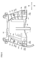
- FIG. 1 is a left side view of a motorcycle according to the present embodiment. It is a top view of the step floor of the two-wheeled motor vehicle of FIG. It is the top view which illustrated the state which removed the step floor of FIG. 2, and the lid. It is the top view which illustrated the state which removed the battery cover and band of FIG. It is a top view of the storage case of FIG.3 and FIG.4. It is a bottom view of the storage case of FIG.
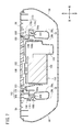
- FIG. 7 is a cross-sectional view taken along the line VII-VII of FIG. 1;
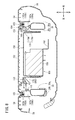
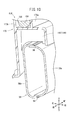
- FIG. 8 is a cross-sectional view taken along line VIII-VIII in FIG. It is the perspective view which fractured and showed a part of storage case and lower frame. It is the perspective view which fractured and showed a part of storage case and lower frame.
- a scooter type motorcycle 10 shown in FIG. 1 will be described as an example.
- the present embodiment is not limited to the scooter type motorcycle 10, and can be applied to other types of vehicles such as a Cub type straddle type vehicle. Further, in the description of the present embodiment, the front, rear, left, right, upper and lower directions will be described according to the direction viewed from the driver (passenger) seated on the motorcycle 10.
- the motorcycle 10 includes a front wheel 12 which is a steering wheel, a steering wheel 14 for steering the front wheel 12, a body frame 16 which constitutes a vehicle body, a unit swing engine 18 which is a drive source, and a rear A wheel 20, a seat 22 and the like are provided.
- the front wheels 12 are provided on the front of the vehicle body and rotatably supported by a pair of left and right front forks 26 extending from the lower end side of the steering shaft 24.
- a front fender 28 covering the upper side of the front wheel 12 is attached to the front fork 26.
- the steering shaft 24 is connected at its upper end to the steering wheel 14, and a substantially middle portion is rotatably held by the head pipe 30 of the vehicle body frame 16.
- the steering wheel 14 extends symmetrically in the vehicle width direction centering on a connecting portion with the steering shaft 24.
- the driver operates steering wheel 14 to change the direction of front wheel 12 connected via steering shaft 24 and front fork 26.
- the body frame 16 is made of a metal material such as aluminum, and includes a head pipe 30, a main frame 32 connected to the head pipe 30, and a seat rail 34 as another frame connected to the rear end of the main frame 32.
- the main frame 32 is connected to a down frame 36 extending downward and rearward from the head pipe 30 and a rear end of the down frame 36, extends rearward at the vehicle bottom, and curves from the vehicle bottom and extends backward.
- a frame 38 A pair of left and right seat rails 34 as rear frames are connected to the rear ends of the pair of left and right lower frames 38.
- the unit swing engine 18 is supported by the pair of left and right lower frames 38 so as to be able to swing up and down.
- fuel tanks 40 for supplying fuel (gasoline) to the unit swing engine 18 are held by the pair of left and right seat rails 34.
- the unit swing engine 18 has an engine and a belt type continuously variable transmission that continuously changes the output of the engine by a transmission belt and a movable pulley and transmits the output to the rear wheel 20.
- the unit swing engine 18 also functions as a swing arm.
- the rear wheel 20 is rotatably supported by the unit swing engine 18, and is rotated by transmission of rotational driving force from the continuously variable transmission to propel the vehicle body as a drive wheel.
- the seat 22 is provided from a substantially middle portion in the front-rear direction of the vehicle body to the rear of the vehicle body.
- the seat 22 is a so-called tandem type seat that includes a front seat 22a on which a driver sits and a rear seat 22b on which a passenger sits behind the front seat 22a.
- a storage box 42 for storing articles is provided below the seat 22 and in front of the fuel tank 40.
- the sheet 22 also has a function as a lid that covers the upper surface of the storage box 42, and the internal space is exposed by pulling the sheet 22 forward. Below the storage box 42, an air cleaner 44 for cleaning the exhaust gas of the engine is disposed below the storage box 42.
- a main stand 46 rotatably supported is provided below the unit swing engine 18, a main stand 46 rotatably supported is provided. At the time of parking, the main stand 46 is erected so as to be substantially orthogonal to the road surface, and the rear wheel 20 is floated to make the motorcycle 10 stand alone.
- the motorcycle 10 forms the appearance of the vehicle body in the longitudinal direction of the vehicle body, and a vehicle body cover 48 made of resin or the like is attached to the vehicle body frame 16, the steering shaft 24, and the like.
- the body cover 48 includes a front cover 50 that covers the front of the steering shaft 24 and the top of the front wheel 12, a handle cover 52 that covers the handle 14 above the front cover 50, and a driver's foot behind the front cover 50.
- a leg shield 53 covering from the front, a floor center cover 56 forming a step floor 54 behind the leg shield 53, and a body cover 58 disposed below the seat 22 and continuously connected to the floor center cover 56 and extending rearward.
- the steering wheel cover 52 covers the upper portion of the steering shaft 24 and the central portion of the steering wheel 14, and a meter device (not shown) for displaying the vehicle speed and the like is provided on the rear upper surface.
- the handle cover 52 is provided with a position light unit 60
- the front cover 50 is provided with a headlight unit 62.
- the step floor 54 is formed flat so that the driver's foot can be placed while traveling.
- the body cover 58 extends upward and rearward from the floor center cover 56 and covers the fuel tank 40, the storage box 42, and the like.
- a rear fender 64 is mounted, which covers the rear wheel 20 from the rear and on which a license plate and the like are arranged.
- a tail lamp 66 is disposed behind the body cover 58. The tail lamp 66 is turned on and off in response to the driver's brake operation.
- the storage case 150 itself receives the load of the step floor 54 (including the load of the driver) and functions as a load transmission structure for transmitting the received load to the lower frame 38.
- a lid 152 flush with the top surface of the step floor 54 is provided at the center of the step floor 54.
- an opening in which the lid 152 is disposed is formed, and an edge 153 defining the opening is formed as a step facing downward. There is.
- the edge (end) of the lid 152 is supported by the edge 153 of the step floor 54, and the upper surface of the lid 152 and the upper surface of the step floor 54 are flush can do.
- the driver's foot gets on the lid 152, the load received by the lid 152 from the driver is transmitted to the edge 153 of the step floor 54 via the edge of the lid 152.
- the lid 152 can be removed from the step floor 54 by loosening the two screws 154 provided on the leg shield 53 side of the lid 152.
- the step floor 54 is fixed to the storage case 150 by two bolts 155 provided on the rear side.
- FIG. 3 is a plan view illustrating the state in which the step floor 54 and the lid 152 are removed.
- the storage case 150 is disposed between the floor center cover 56 in the left-right direction and between the leg shield 53 and the body cover 58 in the front-rear direction in plan view. In this case, the storage case 150 is disposed such that a part of the storage case 150 is placed on the pair of lower frames 38 extending in the front-rear direction inside the floor center cover 56.
- a battery cover 158 covering the battery 156 from above is disposed.
- the battery cover 158 is fixed to the storage case 150 by a band 160.
- the battery cover 158 and the band 160 are disposed immediately below the lid 152. Therefore, when the battery 160 is loosened and the lid 152 is removed, the band 160 is removed, and the battery cover 158 is lifted, the battery 156 and a fuse box 164 described later can be accessed.
- FIG. 4 is a plan view showing the battery cover 158 and the band 160 removed.
- a portion covered by the battery cover 158 is formed as a substantially rectangular battery storage portion 162 recessed downward.
- the battery storage portion 162 stores the battery 156, and the fuse box 164 is stored on the right side of the battery 156.
- each stay 166 is provided to fix and support the storage case 150 to the lower frame 38 and does not have a function of transmitting the load of the step floor 54 described later.
- a grooved harness storage portion 168 is formed in the front-rear direction on the right side of the storage case 150, and the harness storage portion 168 is a linear member.
- a wire harness 104 is placed.
- the harness storage portion 168 is formed by erecting a pair of curved left and right wall portions 170 a and 170 b guiding the wire harness 104 on the right side of the upper surface of the storage case 150. That is, in order to arrange the wire harness 104 along the lower frame 38 on the right side, a space between the wall portions 170 a and 170 b is configured as a harness storage portion 168.
- the load receiving unit 170 is configured to receive a load. That is, in the present embodiment, the wall portions 170 a and 170 b, which are standing walls, are used as the load receiving portion 170.
- the right side wall portion 170 a is formed in accordance with the shape of the right side surface of the storage case 150.
- the left side wall portion 170 b has a shape corresponding to the right side wall portion 170 a and is formed to stand upward from the right end of the battery storage portion 162.
- claw portions 172a and 172b for holding the wire harness 104 arranged in the harness storage portion 168 are provided on the rear side of the right side wall portion 170a and on the front side of the left side wall portion 170b. .
- the wire harness 104 is an electrical component assembled by bundling electric wires connected to the battery 156, the fuse box 164, the ECU, etc., from the front of the motorcycle 10 (around the head pipe 30) to the right of the down frame 36 The rear end of the motorcycle 10 is routed through the harness storage portion 168. Therefore, the battery 156 and the fuse box 164 are connected to the wire branched from the wire harness 104.
- a groove-shaped wire storage portion 174 is formed in the front-rear direction on the left side of the upper surface of the storage case 150, and the rear wheel brake wire 108 and the throttle wire 110 are mounted on the wire storage portion 174.
- the wire storage portion 174 is formed by recessing the upper surface of the storage case 150 downward.
- the rear wheel brake wire 108 is a linear member for transmitting the brake operation force resulting from the operation of the interlocking brake lever 114 by the driver to the rear wheel brake 116, and from above the head pipe 30, the head pipe 30, the down frame 36 It is routed to the rear wheel brake 116 through the left side and the wire storage portion 174.
- the throttle wire 110 transmits the amount of rotational operation of the handle grip on the right side (not shown) by the driver to the throttle device 118, and the left side of the head pipe 30, the down frame 36 and the wire storage portion 174 from above the head pipe 30. Are routed to reach the throttle device 118.
- a clamp portion 176 for holding the rear wheel brake wire 108 and the throttle wire 110 arranged in the wire storage portion 174 is provided.
- a wall portion 178 having a larger planar area than the two wall portions 170a and 170b is provided between the left end of the battery storage portion 162 and the wire storage portion 174.
- the cylindrical portion 180 is erected.
- the wall portion 178 and the cylindrical portion 180 are also configured as a load receiving portion 182 that receives the load of the step floor 54 by contacting the bottom surface (the edge 153 or the like on the left side) of the step floor 54.
- screw holes 179 a and 179 b in which bolts 155 are screwed are provided on the upper surface of the storage case 150 near the claws 172 b and in the vicinity of the clamps 176.
- the formed protrusions 181a and 181b are respectively formed.
- the projecting portions 181 a and 181 b project upward and contact the bottom surface of the step floor 54 to form load receiving portions 183 a and 183 b that receive the load of the step floor 54.
- the upper surface of the storage case 150 is provided with a pair of left and right load receiving portions 170, 182, 183a which receive the load of the step floor 54,
- a battery storage portion 162 for storing the battery 156 and the fuse box 164 is formed between the load receiving portions 170, 182, 183a and 183b.
- two ribs 184a and 184b extending in the front-rear direction along the harness storage portion 168 are formed immediately below the harness storage portion 168.
- two ribs 184a and 184b are formed between two wall parts 170a and 170b which constitute load receiving part 170 in plane view.
- the two ribs 184a and 184b are connected by a rib 186 which is a bridge portion which is provided below the storage case 150 and which extends downward in the left-right direction.
- the pair of left and right lower frames 38 abuts on the right and left end portions of the right and left frame portions 38 a and 38 b in an intermediate manner and welds the abutting portions. And so on. That is, the bead is formed by welding in the state where the upper and lower ends of the right side frame portion 38a and the upper and lower ends of the left side frame portion 38b overlap each other.
- the lower frame 38 is formed by the bead functioning as a coupling portion 94 that couples the right side frame portion 38a and the left side frame portion 38b.
- one rib 184a of the two ribs 184a and 184b contacts the upper end portion of the right side frame portion 38a that constitutes the lower frame 38 on the right side, and the other rib 184b is on the left side that constitutes the lower frame 38 Contact the upper end portion of the frame portion 38b. That is, the pair of ribs 184a and 184b respectively contact the upper end portions of the right side frame portion 38a and the left side frame portion 38b in a state of being formed along the coupling portion 94 of the lower frame 38 extending in the front and rear direction.
- the two ribs 184 a and 184 b function as a load transfer unit 184 that transfers the load of the step floor 54 received by the load receiving unit 170 to the lower frame 38.
- two ribs 188a and 188b extending in the front-rear direction are formed in a portion immediately below the cylindrical portion 180 which constitutes the load receiving portion 182.
- the two ribs 188a and 188b are connected to each other by a rib 190 which is a bridge extending vertically downward on the back surface of the storage case 150 and extending in the left-right direction.
- one rib 188a of the two ribs 188a and 188b contacts the upper end portion of the right side frame portion 38a constituting the lower frame 38 on the left side, and the other rib 188b constitutes the lower frame 38.
- the pair of ribs 188a and 188b contact the upper end portions of the right side frame portion 38a and the left side frame portion 38b, respectively, in a state of being formed along the coupling portion 94 of the lower frame 38 extending in the front and rear direction.
- the two ribs 188 a and 188 b function as a load transfer unit 188 that transfers the load of the step floor 54 received by the load receiving unit 182 to the lower frame 38.
- a rib 187a is provided at a location near the projecting portion 181a (load receiving portion 183a), which stands downward along the longitudinal direction and contacts the lower frame 38 on the right side.
- a rib 187b is provided at a position near the protrusion 181b (load receiving portion 183b), which stands downward along the front-rear direction and contacts the lower frame 38 on the left side.
- the ribs 187a and 187b function as load transmitting portions 189a and 189b for transmitting the load of the step floor 54 received by the load receiving portions 183a and 183b to the left and right lower frames 38.
- the bottom of the storage case 150 is provided with a pair of left and right load transfer parts 184 and 188 for transferring the load of the step floor 54 to the pair of lower frames 38 on the left and right, 189a and 189b are provided, and a battery storage portion 162 for storing the battery 156 and the fuse box 164 is formed between the load transfer portions 184, 188, 189a and 189b. Further, as shown in FIGS.
- At least a part of the wire harness 104, the rear wheel brake wire 108, the throttle wire 110, the battery 156 and the fuse box 164 when viewed from the left and right (when viewed from the side) are accommodated in the storage case 150 so as to overlap the load transfer units 184, 188, 189a, 189b.
- the ribs 184a, 184b, 187a, 187b, 188a, 188b extending in the front-rear direction have been described as functioning as the load transfer parts 184, 188, 189a, 189b.
- the rib (s) 192 extending in the left-right direction may function as the load transfer portion 194.
- at least part of the wire harness 104, the rear wheel brake wire 108, the throttle wire 110, the battery 156, and the fuse box 164 overlaps the load transfer portion 194 when viewed from the left and right (when viewed from the side) Are stored in the storage case 150.
- the ribs 186 connecting the ribs 184a and 184b can be made to contact the upper end portion of the right side frame portion 38a and the upper end portion of the left side frame portion 38b to function as part of the load transfer portion 184.
- the ribs 190 connecting the ribs 188a and 188b can be made to contact the upper end portion of the right side frame portion 38a and the upper end portion of the left side frame portion 38b to function as part of the load transfer portion 188.
- by providing a plurality of ribs 186, 190, 192 extending in the left-right direction at predetermined intervals in the front-rear direction it is also possible to function as part of the load transfer parts 184, 188, 194.
- the load transfer portions 184, 188, 189a, 189b may be configured by only the ribs 184a, 184b, 187a, 187b, 188a, 188b extending in the front-rear direction, or extend in the left-right direction
- the load transfer portions 184 and 188 may be configured to include the ribs 186 and 190.
- the load transfer portions 184, 188, 194 may be configured by only the ribs 186, 190, 192 extending in the left-right direction.
- the load receiving portions 170, 182, 183a, 183b for receiving the load of the step floor 54, and the load transmitting portion 184 for transmitting the load to the lower frame 38 Since the storage case 150 integrally comprises 188, 189a, 189b and 194, the storage case 150 stores the wire harness 104, the rear wheel brake wire 108, the throttle wire 110, the battery 156 and the fuse box 164 which are stored items. At the same time, the load of the step floor 54 including the load of the occupant can be transmitted to the lower frame 38. As a result, a dedicated load transfer structure is not required, and the cost of the motorcycle 10 can be reduced.
- the load of the step floor 54 can be properly transmitted to the lower frame 38.
- the load of the step floor 54 can be properly transmitted to the lower frame 38.
- the load of the step floor 54 can be stored in a space-saving manner while appropriately transmitting to the lower frame 38.
- the load transfer portions 184, 188, 189a, 189b are constituted by the ribs 184a, 184b, 187a, 187b, 188a, 188b along the longitudinal direction (front-rear direction) of the lower frame 38, the load of the step floor 54
- the lower frame 38 can be appropriately transmitted along the front-rear direction.
- the load transfer parts 184, 188 and 194 are ribs 186, 190 and 192 along the lateral direction (lower and right directions) of the lower frame 38, the load of the step floor 54 is appropriately lower along the lateral direction. It can be conveyed to frame 38.
- the load of the step floor 54 can be efficiently transmitted to the lower frame 38.
- the wire harness 104, the rear wheel brake wire 108, and the throttle wire 110 which are linear members, overlap the lower frame 38, and at least a portion of the storage case 150 is a linear member and the lower frame. Since the linear member is disposed between the lower frame 38 and the lower frame 38, the linear member can be stored in the storage case 150 while being protected from the lower frame 38.
- the stored items stored in the storage case 150 include the wire harness 104, the rear wheel brake wire 108 and the throttle wire 110, which are linear members, the battery 156, and the fuse box 164.
- the case was described.
- the present invention even when other linear members and stored items are stored in the storage case 150, the present invention is applicable.
- the present embodiment can be applied to a motorcycle 10 having a powertrain at a position different from the above description. It is.
- this embodiment can be applied to a motorcycle in which the powertrain is disposed below the main frame.
Landscapes
- Engineering & Computer Science (AREA)
- Mechanical Engineering (AREA)
- Automatic Cycles, And Cycles In General (AREA)
- Fittings On The Vehicle Exterior For Carrying Loads, And Devices For Holding Or Mounting Articles (AREA)
Abstract
自動二輪車(10)において、収納ケース(150)は、ステップフロア(54)の荷重を受ける荷重受部(170、182、183a、183b)と、該荷重受部(170、182、183a、183b)が受けた荷重をロアフレーム(38)に伝える荷重伝達部(184、188、189a、189b、194)とを一体に備える。
Description
本発明は、乗員の荷重を受けるステップフロアと、該ステップフロアの下方に配置されたフレームと、ステップフロア及びフレームによって形成された空間に収納物を収納する収納ケースとを備えた車両に関する。
従来より、ステップフロアを備える車両であって、ステップフロアの下方に、電装品やケーブル類等の収納物を収納可能な収納ケースを備えた車両が、例えば、特開2003-341573号公報及び特開2015-193364号公報に開示されている。
このような車両では、ステップフロアにかかる乗員の荷重を車両のフレームで受ける必要がある。そのため、一般に、ステップフロアで受けた荷重は、該ステップフロアからフレームに直接伝達されるか、又は、ステップフロアからステーを介してフレームに伝達される。この場合、ステップフロアからフレームに荷重を伝達させる荷重伝達構造を別途設ける必要があるので、車両のコストがかかるという課題がある。
そこで、本発明は、専用の荷重伝達構造を設けることなく、コストを低減することができる車両を提供することを目的とする。
本発明に係る車両は、乗員の荷重を受けるステップフロアと、該ステップフロアの下方に配置されたフレームと、前記ステップフロア及び前記フレームによって形成された空間に収納物を収納する収納ケースとを備えた車両であって、以下の特徴を有する。
第1の特徴;前記収納ケースは、前記ステップフロアの荷重を受ける荷重受部と、受けた前記荷重を前記フレームに伝える荷重伝達部とを一体に備える。
第2の特徴;前記荷重伝達部は、平面視で、少なくとも一部が前記フレームと重なるように形成されている。
第3の特徴;前記荷重受部は、平面視で、少なくとも一部が前記フレームと重なるように形成されている。
第4の特徴;前記荷重伝達部は、前記収納ケースに少なくとも一対備わり、前記収納物は、一対の前記荷重伝達部の間に収納されている。
第5の特徴;前記収納物は、側面視で、少なくとも一部が前記荷重伝達部と重なるように前記収納ケースに収納されている。
第6の特徴;前記荷重伝達部は、前記フレームの長手方向に沿って形成されたリブである。
第7の特徴;前記荷重伝達部は、前記フレームの短手方向に沿って形成されたリブである。
第8の特徴;前記収納物は、線状部材を含み、前記線状部材の少なくとも一部は、平面視で、前記フレームと重なり、前記収納ケースの少なくとも一部は、前記線状部材と前記フレームとの間に配置されている。
本発明の第1の特徴によれば、前記ステップフロアの荷重を受ける前記荷重受部と、前記荷重を前記フレームに伝える前記荷重伝達部とを前記収納ケースが一体に備えるので、前記収納ケースは、前記収納物を収納しつつ、(前記乗員の荷重を含む)前記ステップフロアの荷重を前記フレームに伝えることができる。これにより、専用の荷重伝達構造が不要となるので、前記車両のコストを低減することができる。
本発明の第2の特徴によれば、前記荷重伝達部の少なくとも一部が前記フレームと重なるので、前記ステップフロアの荷重を適切に前記フレームに伝えることができる。
本発明の第3の特徴によれば、前記荷重受部の少なくとも一部が前記フレームと重なるので、前記ステップフロアの荷重を適切に前記フレームに伝えることができる。
本発明の第4の特徴によれば、前記収納ケースに備わる一対の前記荷重伝達部の間に前記収納物が収納されるので、前記ステップフロアの荷重を適切に前記フレームに伝えつつ、前記収納物を収納することができる。
本発明の第5の特徴によれば、側面視で、前記収納物の少なくとも一部が前記荷重伝達部と重なるように前記収納ケースに収納されるので、前記ステップフロアの荷重を適切に前記フレームに伝えつつ、前記収納物を省スペースに収納することができる。
本発明の第6の特徴によれば、前記荷重伝達部が前記フレームの長手方向に沿ったリブであるため、前記ステップフロアの荷重を前記長手方向に沿って適切に前記フレームに伝えることができる。
本発明の第7の特徴によれば、前記荷重伝達部が前記フレームの短手方向に沿ったリブであるため、前記ステップフロアの荷重を前記短手方向に沿って適切に前記フレームに伝えることができる。
本発明の第8の特徴によれば、前記収納物である前記線状部材の少なくとも一部が前記フレームと重なり、前記収納ケースの少なくとも一部が前記線状部材と前記フレームとの間に配置されるので、前記線状部材を前記フレームから保護しつつ、前記収納ケースに収納することができる。
本発明について、好適な実施形態を掲げ、添付の図面を参照しながら、以下詳細に説明する。
[自動二輪車10の概略構成]
本発明の一実施形態として、図1に示すスクータ型の自動二輪車10を例に挙げて説明する。なお、本実施形態は、スクータ型の自動二輪車10に限定されるものではなく、カブ型の鞍乗型車両等の他の種類の車両にも適用可能である。また、本実施形態の説明では、自動二輪車10に着座した運転者(乗員)から見た方向に従って、前後、左右及び上下の方向を説明する。
本発明の一実施形態として、図1に示すスクータ型の自動二輪車10を例に挙げて説明する。なお、本実施形態は、スクータ型の自動二輪車10に限定されるものではなく、カブ型の鞍乗型車両等の他の種類の車両にも適用可能である。また、本実施形態の説明では、自動二輪車10に着座した運転者(乗員)から見た方向に従って、前後、左右及び上下の方向を説明する。
図1に示すように、自動二輪車10は、操舵輪である前輪12、該前輪12を操舵するハンドル14、車体を構成する車体フレーム16、駆動源であるユニットスイングエンジン18、駆動輪である後輪20及びシート22等を備える。
前輪12は、車体の前方に設けられ、ステアリング軸24の下端側から延在する左右一対のフロントフォーク26に回転自在に軸支される。このフロントフォーク26には前輪12の上方を覆うフロントフェンダ28が取り付けられる。ステアリング軸24は、上端側にハンドル14が連結されると共に、略中間部が車体フレーム16のヘッドパイプ30に回動自在に保持される。
ハンドル14は、ステアリング軸24との連結部分を中心として車幅方向に左右対称に延設されている。運転者がハンドル14を操作することによって、ステアリング軸24及びフロントフォーク26を介して連結されている前輪12の向きを変更させる。
車体フレーム16は、アルミニウム等の金属材料からなり、ヘッドパイプ30と、ヘッドパイプ30に連結されるメインフレーム32と、メインフレーム32の後端に連結される他のフレームとしてのシートレール34とから構成される。メインフレーム32は、ヘッドパイプ30から下側後方に延びるダウンフレーム36と、ダウンフレーム36の後端に連結され、車体底部で後方に延び、車体底部から湾曲して車体後方に延びる左右一対のロアフレーム38とから構成される。左右一対のロアフレーム38の後端にリアフレームとしての左右一対のシートレール34が連結される。
ユニットスイングエンジン18は、上下揺動可能に左右一対のロアフレーム38に支承される。また、車体の後方上部では、ユニットスイングエンジン18に燃料(ガソリン)を供給する燃料タンク40が左右一対のシートレール34に保持される。
ユニットスイングエンジン18は、図示しないが、エンジンと、当該エンジンの出力を伝達ベルト及び可動プーリによって無段階に変速して後輪20に伝達するベルト式の無段変速機とを有する。また、ユニットスイングエンジン18は、スイングアームとしても機能する。後輪20は、ユニットスイングエンジン18により回転自在に軸支され、無段変速機から回転駆動力が伝達されることで回転し、駆動輪として車体を推進させる。
シート22は、車体の前後方向略中間部から車体後方にかけて設けられている。シート22は、運転者が着座するフロントシート22aと、フロントシート22aの後方で同乗者が着座するリアシート22bとからなる、いわゆるタンデム型のシートが採用されている。シート22の下方であって、燃料タンク40の前方には、物品を収容するための収納ボックス42が設けられている。シート22は、収納ボックス42の上面を覆う蓋としての機能を兼ねており、該シート22を前方に引き上げることにより内部の空間が露呈される。収納ボックス42の下方には、エンジンの排気ガスを清浄化するエアクリーナ44が配設されている。
ユニットスイングエンジン18の下方には、回動可能に支持されたメインスタンド46が設けられている。メインスタンド46は、駐車時に路面と略直交となるように起立されて後輪20を浮かせて自動二輪車10を自立させる。
そして、自動二輪車10は、車体前後方向にかけて、該車体の外観を構成し、且つ、樹脂等からなる車体カバー48が、車体フレーム16、ステアリング軸24等に取り付けられている。車体カバー48は、ステアリング軸24の前部及び前輪12の上部を覆うフロントカバー50と、当該フロントカバー50の上方においてハンドル14を覆うハンドルカバー52と、フロントカバー50の後方で運転者の足を前方から覆うレッグシールド53と、レッグシールド53の後方でステップフロア54を形成するフロアセンタカバー56と、シート22の下方に配置されると共に、フロアセンタカバー56に連設されて後方に延びるボディカバー58とを備える。
また、ハンドルカバー52は、ステアリング軸24の上部及びハンドル14の中央部分を覆っており、その後方上面には、車速等を表示する図示しないメータ装置が設けられている。ハンドルカバー52には、ポジションライト部60が設けられ、フロントカバー50には、ヘッドライト部62が設けられている。
ステップフロア54は、走行中に運転者の足が乗せられるように平坦状に形成されている。ボディカバー58は、フロアセンタカバー56から上方及び後方に延設され、燃料タンク40及び収納ボックス42等を覆う。ボディカバー58の後側の下部には、後輪20を後方から覆うと共に、ライセンスプレート等が配置されるリアフェンダ64が取り付けられている。また、ボディカバー58の後方には、テールランプ66が配設されている。このテールランプ66は、運転者のブレーキ操作に反応して点灯及び消灯する。
[ステップフロア54下の荷重伝達構造]
次に、本実施形態に係る自動二輪車10の特徴的な構成であるステップフロア54下の荷重伝達構造について、図2~図10を参照しながら説明する。
次に、本実施形態に係る自動二輪車10の特徴的な構成であるステップフロア54下の荷重伝達構造について、図2~図10を参照しながら説明する。
この荷重伝達構造は、フロントシート22aに着座した運転者の足がステップフロア54に乗る場合に、ステップフロア54が運転者から受ける荷重を、ステップフロア54下に設けられた収納ケース150を介して、ロアフレーム38に伝達する構造である。すなわち、収納ケース150自体が(運転者の荷重を含む)ステップフロア54の荷重を受け、受けた荷重をロアフレーム38に伝達する荷重伝達構造として機能する。
図2に示すように、ステップフロア54の中央には、該ステップフロア54の上面と面一のリッド152が設けられている。図7及び図8に示すように、ステップフロア54の中心には、リッド152が配置される開口部が形成され、開口部を画成する縁部153は、下方に向かう段差部として形成されている。これにより、開口部をリッド152で塞いだときに、リッド152の縁部(端部)がステップフロア54の縁部153に支持され、リッド152の上面とステップフロア54の上面とを面一にすることができる。また、運転者の足がリッド152に乗ったときに、運転者からリッド152が受ける荷重は、リッド152の縁部を介して、ステップフロア54の縁部153に伝達される。
なお、リッド152のレッグシールド53側に設けられた2つのビス154を緩めることにより、リッド152をステップフロア54から取り外すことができる。また、ステップフロア54は、後部側に設けられた2つのボルト155によって収納ケース150に固定されている。
図3は、ステップフロア54及びリッド152を取り外した状態を図示した平面図である。収納ケース150は、平面視で、左右方向についてはフロアセンタカバー56間、前後方向についてはレッグシールド53とボディカバー58との間に配置されている。この場合、フロアセンタカバー56内方で前後方向に延びる左右一対のロアフレーム38に収納ケース150の一部が載置されるように、該収納ケース150が配置されている。
収納ケース150の中央部には、バッテリ156を上方から覆うバッテリカバー158が配置されている。バッテリカバー158は、帯状のバンド160によって収納ケース150に固定されている。なお、バッテリカバー158及びバンド160は、リッド152直下に配置されている。従って、ビス154を緩めてリッド152を取り外した状態でバンド160を外し、バッテリカバー158を持ち上げると、バッテリ156、及び、後述のヒューズボックス164にアクセスすることが可能となる。
図4は、バッテリカバー158及びバンド160を取り外した状態を示した平面図である。収納ケース150の中央部において、バッテリカバー158で覆われる部分は、下方に凹んだ略矩形状のバッテリ収納部162として形成されている。バッテリ収納部162には、バッテリ156が収納されると共に、該バッテリ156の右側にヒューズボックス164が収納されている。
図3及び図4に示すように、収納ケース150の前端は、左右一対のステー166を介して左右一対のロアフレーム38に固定支持されている。なお、各ステー166は、収納ケース150をロアフレーム38に固定支持するために設けられるものであり、後述するステップフロア54の荷重を伝達する機能を有しないことに留意する。
そして、図3~図5、図7及び図8に示すように、収納ケース150の右側には、溝状のハーネス収納部168が前後方向に形成され、該ハーネス収納部168に線状部材であるワイヤハーネス104が載置されている。
具体的に、ハーネス収納部168は、収納ケース150の上面の右側において、ワイヤハーネス104をガイドする曲線状の左右一対の壁部170a、170bが上方に立設することにより形成される。すなわち、右側のロアフレーム38に沿ってワイヤハーネス104を配索するため、各壁部170a、170b間がハーネス収納部168として構成される。
そして、図7及び図8に示すように、ワイヤハーネス104のガイドである各壁部170a、170bは、ステップフロア54の底面(右側の縁部153等)に接触することにより、ステップフロア54の荷重を受ける荷重受部170として構成される。すなわち、本実施形態では、立壁である各壁部170a、170bを荷重受部170として利用する。
図3~図5に示すように、右側の壁部170aは、収納ケース150の右側面の形状に合わせて形成されている。また、左側の壁部170bは、右側の壁部170aに対応する形状を有し、バッテリ収納部162の右端から上方に立設するように形成されている。さらに、右側の壁部170aの後方と、左側の壁部170bの前方とには、ハーネス収納部168に配索されたワイヤハーネス104を保持するための爪部172a、172bがそれぞれ設けられている。
なお、ワイヤハーネス104は、バッテリ156、ヒューズボックス164、ECU等に接続される電線を束にして集合させた電装部品であり、自動二輪車10の前方(ヘッドパイプ30周辺)からダウンフレーム36の右側及びハーネス収納部168を通って自動二輪車10の後方にまで至るように配索されている。従って、バッテリ156及びヒューズボックス164は、ワイヤハーネス104から分岐した電線に接続される。
一方、収納ケース150の上面の左側には、溝状のワイヤ収納部174が前後方向に形成され、該ワイヤ収納部174に後輪ブレーキワイヤ108及びスロットルワイヤ110が載置されている。具体的に、ワイヤ収納部174は、収納ケース150の上面を下方に凹ませることにより形成される。
後輪ブレーキワイヤ108は、運転者による連動ブレーキレバー114の操作に起因したブレーキ操作力を後輪ブレーキ116に伝達する線状部材であり、ヘッドパイプ30上方から、ヘッドパイプ30、ダウンフレーム36の左側及びワイヤ収納部174を通って後輪ブレーキ116に至るように配索されている。
スロットルワイヤ110は、運転者による図示しない右側のハンドルグリップの回動操作量をスロットル装置118に伝達するものであり、ヘッドパイプ30上方から、ヘッドパイプ30、ダウンフレーム36の左側及びワイヤ収納部174を通ってスロットル装置118に至るように配索されている。
なお、ワイヤ収納部174の後方には、ワイヤ収納部174に配索された後輪ブレーキワイヤ108及びスロットルワイヤ110を保持するクランプ部176が設けられている。
また、収納ケース150の上面の左側において、バッテリ収納部162の左端とワイヤ収納部174との間には、2つの壁部170a、170bよりも大きな平面積を有する壁部178が上方に立設すると共に、円筒部180が立設している。壁部178及び円筒部180も、ステップフロア54の底面(左側の縁部153等)に接触することにより、ステップフロア54の荷重を受ける荷重受部182として構成される。
さらに、図3~図5及び図8に示すように、収納ケース150の上面における爪部172b近傍の箇所とクランプ部176近傍の箇所とには、ボルト155が螺合するねじ孔179a、179bが形成された突出部181a、181bがそれぞれ形成されている。突出部181a、181bは、上方に突出し、ステップフロア54の底面に接触することにより、ステップフロア54の荷重を受ける荷重受部183a、183bとして構成される。
従って、図3~図5、図7及び図8に示すように、本実施形態において、収納ケース150の上面には、ステップフロア54の荷重を受ける左右一対の荷重受部170、182、183a、183bが設けられ、これらの荷重受部170、182、183a、183b間に、バッテリ156及びヒューズボックス164を収納するバッテリ収納部162が形成されている。
図6~図9に示すように、収納ケース150の裏面において、ハーネス収納部168直下の箇所には、ハーネス収納部168に沿って前後方向に延在する2つのリブ184a、184bが形成されている。すなわち、2つのリブ184a、184bは、平面視で、荷重受部170を構成する2つの壁部170a、170bの間に形成されている。2つのリブ184a、184bは、収納ケース150の裏面で下方に立設し、且つ、左右方向に延在するブリッジ部であるリブ186によって連結されている。
ここで、左右一対のロアフレーム38は、図7~図9に示すように、右側フレーム部38aと左側フレーム部38bとを、上下の両端部分で最中合わせに当接し、当接部分を溶接等で結合することにより形成される。すなわち、右側フレーム部38aの上下の両端と、左側フレーム部38bの上下の両端とが互いに重なり合った状態で、溶接を施すことでビードが形成される。該ビードが右側フレーム部38aと左側フレーム部38bとを結合させる結合部94として機能することにより、ロアフレーム38が形成される。
そして、2つのリブ184a、184bのうち、一方のリブ184aは、右側のロアフレーム38を構成する右側フレーム部38aの上端部分に接触し、他方のリブ184bは、該ロアフレーム38を構成する左側フレーム部38bの上端部分に接触する。すなわち、一対のリブ184a、184bは、前後方向に延在するロアフレーム38の結合部94に沿って形成された状態で、右側フレーム部38a及び左側フレーム部38bの上端部分にそれぞれ接触する。これにより、2つのリブ184a、184bは、荷重受部170が受けたステップフロア54の荷重をロアフレーム38に伝達する荷重伝達部184として機能する。
一方、収納ケース150の裏面において、荷重受部182を構成する円筒部180直下の箇所には、前後方向に延在する2つのリブ188a、188bが形成されている。2つのリブ188a、188bは、収納ケース150の裏面で下方に立設し、且つ、左右方向に延在するブリッジ部であるリブ190によって連結されている。
この場合も、2つのリブ188a、188bのうち、一方のリブ188aは、左側のロアフレーム38を構成する右側フレーム部38aの上端部分に接触し、他方のリブ188bは、該ロアフレーム38を構成する左側フレーム部38bの上端部分に接触する。すなわち、一対のリブ188a、188bは、前後方向に延在するロアフレーム38の結合部94に沿って形成された状態で、右側フレーム部38a及び左側フレーム部38bの上端部分にそれぞれ接触する。これにより、2つのリブ188a、188bは、荷重受部182が受けたステップフロア54の荷重をロアフレーム38に伝達する荷重伝達部188として機能する。
さらに、収納ケース150の裏面において、突出部181a(荷重受部183a)近傍の箇所には、前後方向に沿って下方に立設し、右側のロアフレーム38に接触するリブ187aが形成されている。また、収納ケース150の裏面において、突出部181b(荷重受部183b)近傍の箇所には、前後方向に沿って下方に立設し、左側のロアフレーム38に接触するリブ187bが形成されている。これらのリブ187a、187bは、荷重受部183a、183bが受けたステップフロア54の荷重を左右一対のロアフレーム38に伝達する荷重伝達部189a、189bとして機能する。
従って、図6~図9に示すように、本実施形態において、収納ケース150の底面には、ステップフロア54の荷重を左右一対のロアフレーム38に伝達する左右一対の荷重伝達部184、188、189a、189bが設けられ、これらの荷重伝達部184、188、189a、189b間に、バッテリ156及びヒューズボックス164を収納するバッテリ収納部162が形成されている。また、図7及び図8に示すように、左右方向から見たとき(側面から見たとき)、ワイヤハーネス104、後輪ブレーキワイヤ108、スロットルワイヤ110、バッテリ156及びヒューズボックス164の少なくとも一部は、荷重伝達部184、188、189a、189bと重なるように収納ケース150に収納されている。
なお、上記の説明では、前後方向に延在するリブ184a、184b、187a、187b、188a、188bが荷重伝達部184、188、189a、189bとして機能する場合について説明したが、本実施形態では、図10に示すように、左右方向に延在する(複数の)リブ192を荷重伝達部194として機能させてもよい。この場合でも、左右方向から見たとき(側面から見たとき)、ワイヤハーネス104、後輪ブレーキワイヤ108、スロットルワイヤ110、バッテリ156及びヒューズボックス164の少なくとも一部は、荷重伝達部194と重なるように収納ケース150に収納されている。
また、各リブ184a、184bを連結するリブ186について、右側フレーム部38aの上端部分と左側フレーム部38bの上端部分とに接触させ、荷重伝達部184の一部として機能させることも可能である。さらに、各リブ188a、188bを連結するリブ190について、右側フレーム部38aの上端部分と左側フレーム部38bの上端部分とに接触させ、荷重伝達部188の一部として機能させることも可能である。さらにまた、左右方向に延在するリブ186、190、192を、前後方向に所定間隔で複数設けることにより、荷重伝達部184、188、194の一部として機能させることも可能である。
つまり、本実施形態において、荷重伝達部184、188、189a、189bは、左右一対のロアフレーム38に接触して、ステップフロア54の荷重を該ロアフレーム38に伝達できるものであれば、どのようなリブであってもよい。従って、前述のように、前後方向に延在するリブ184a、184b、187a、187b、188a、188bのみで荷重伝達部184、188、189a、189bを構成してもよいし、左右方向に延在するリブ186、190も含めて荷重伝達部184、188を構成してもよい。あるいは、左右方向に延在するリブ186、190、192のみで荷重伝達部184、188、194を構成してもよい。
[本実施形態の効果]
以上説明したように、本実施形態に係る自動二輪車10によれば、ステップフロア54の荷重を受ける荷重受部170、182、183a、183bと、該荷重をロアフレーム38に伝える荷重伝達部184、188、189a、189b、194とを収納ケース150が一体に備えるので、収納ケース150は、収納物であるワイヤハーネス104、後輪ブレーキワイヤ108、スロットルワイヤ110、バッテリ156及びヒューズボックス164を収納しつつ、乗員の荷重を含むステップフロア54の荷重をロアフレーム38に伝えることができる。これにより、専用の荷重伝達構造が不要となるので、自動二輪車10のコストを低減することができる。
以上説明したように、本実施形態に係る自動二輪車10によれば、ステップフロア54の荷重を受ける荷重受部170、182、183a、183bと、該荷重をロアフレーム38に伝える荷重伝達部184、188、189a、189b、194とを収納ケース150が一体に備えるので、収納ケース150は、収納物であるワイヤハーネス104、後輪ブレーキワイヤ108、スロットルワイヤ110、バッテリ156及びヒューズボックス164を収納しつつ、乗員の荷重を含むステップフロア54の荷重をロアフレーム38に伝えることができる。これにより、専用の荷重伝達構造が不要となるので、自動二輪車10のコストを低減することができる。
また、平面視で、荷重伝達部184、188、189a、189b、194の少なくとも一部がロアフレーム38と重なるので、ステップフロア54の荷重を適切にロアフレーム38に伝えることができる。
さらに、平面視で、荷重受部170、182、183a、183bの少なくとも一部がロアフレーム38と重なるので、ステップフロア54の荷重を適切にロアフレーム38に伝えることができる。
さらにまた、収納ケース150に備わる左右一対の荷重伝達部184、188、189a、189b、194間に上記の各収納物が収納されるので、ステップフロア54の荷重を適切にロアフレーム38に伝えつつ、各収納物を収納することができる。
また、側面視で、ワイヤハーネス104、後輪ブレーキワイヤ108、スロットルワイヤ110が荷重伝達部184、188、189a、189b、194と重なるように収納ケース150に収納されるので、ステップフロア54の荷重を適切にロアフレーム38に伝えつつ、各収納物を省スペースに収納することができる。
さらに、荷重伝達部184、188、189a、189bがロアフレーム38の長手方向(前後方向)に沿ったリブ184a、184b、187a、187b、188a、188bによって構成されるので、ステップフロア54の荷重を前後方向に沿って適切にロアフレーム38に伝えることができる。
あるいは、荷重伝達部184、188、194がロアフレーム38の短手方向(左右方向)に沿ったリブ186、190、192である場合でも、ステップフロア54の荷重を左右方向に沿って適切にロアフレーム38に伝えることができる。この場合、リブ186、190、192を前後方向に所定間隔で複数設ければ、ステップフロア54の荷重を効率よくロアフレーム38に伝えることが可能となる。
さらにまた、平面視で、線状部材であるワイヤハーネス104、後輪ブレーキワイヤ108、スロットルワイヤ110の少なくとも一部がロアフレーム38と重なり、収納ケース150の少なくとも一部が線状部材とロアフレーム38との間に配置されるので、線状部材をロアフレーム38から保護しつつ、収納ケース150に収納することができる。
[本実施形態の変形例]
本実施形態に係る自動二輪車10では、収納ケース150に収納される収納物が、線状部材であるワイヤハーネス104、後輪ブレーキワイヤ108及びスロットルワイヤ110と、バッテリ156と、ヒューズボックス164とである場合について説明した。本実施形態では、収納ケース150に他の線状部材や収納物が収納される場合でも、適用可能であることは勿論である。
本実施形態に係る自動二輪車10では、収納ケース150に収納される収納物が、線状部材であるワイヤハーネス104、後輪ブレーキワイヤ108及びスロットルワイヤ110と、バッテリ156と、ヒューズボックス164とである場合について説明した。本実施形態では、収納ケース150に他の線状部材や収納物が収納される場合でも、適用可能であることは勿論である。
また、本実施形態では、ユニットスイングエンジン18を有する自動二輪車10について説明したが、上記の説明と異なる位置にパワートレインが備わる自動二輪車10に対しても本実施形態を適用可能であることは勿論である。例えば、特開2008-162527号公報に開示されている自動二輪車のように、メインフレームの下方にパワートレインが配置される自動二輪車に本実施形態を適用可能である。
以上、本発明について好適な実施形態を用いて説明したが、本発明の技術的範囲は、上記の実施形態の記載範囲に限定されることはない。上記の実施形態に、多様な変更又は改良を加えることが可能であることは、当業者に明らかである。そのような変更又は改良を加えた形態も、本発明の技術的範囲に含まれ得ることが、特許請求の範囲の記載から明らかである。また、特許請求の範囲に記載された括弧書きの符号は、本発明の理解の容易化のために添付図面中の符号に倣って付したものであり、本発明がその符号をつけた要素に限定されて解釈されるものではない。
Claims (8)
- 乗員の荷重を受けるステップフロア(54)と、該ステップフロア(54)の下方に配置されたフレーム(38)と、前記ステップフロア(54)及び前記フレーム(38)によって形成された空間に収納物(104、108、110、156、164)を収納する収納ケース(150)とを備えた車両(10)において、
前記収納ケース(150)は、前記ステップフロア(54)の荷重を受ける荷重受部(170、182、183a、183b)と、受けた前記荷重を前記フレーム(38)に伝える荷重伝達部(184、188、189a、189b、194)とを一体に備えることを特徴とする車両(10)。 - 請求項1記載の車両(10)において、
前記荷重伝達部(184、188、189a、189b、194)は、平面視で、少なくとも一部が前記フレーム(38)と重なるように形成されていることを特徴とする車両(10)。 - 請求項1又は2記載の車両(10)において、
前記荷重受部(170、182、183a、183b)は、平面視で、少なくとも一部が前記フレーム(38)と重なるように形成されていることを特徴とする車両(10)。 - 請求項1~3のいずれか1項に記載の車両(10)において、
前記荷重伝達部(184、188、189a、189b、194)は、前記収納ケース(150)に少なくとも一対備わり、
前記収納物(104、108、110、156、164)は、一対の前記荷重伝達部(184、188、189a、189b、194)の間に収納されていることを特徴とする車両(10)。 - 請求項1~4のいずれか1項に記載の車両(10)において、
前記収納物(104、108、110、156、164)は、側面視で、少なくとも一部が前記荷重伝達部(184、188、189a、189b、194)と重なるように前記収納ケース(150)に収納されていることを特徴とする車両(10)。 - 請求項1~5のいずれか1項に記載の車両(10)において、
前記荷重伝達部(184、188、189a、189b)は、前記フレーム(38)の長手方向に沿って形成されたリブ(184a、184b、187a、187b、188a、188b)であることを特徴とする車両(10)。 - 請求項1~6のいずれか1項に記載の車両(10)において、
前記荷重伝達部(184、188、194)は、前記フレーム(38)の短手方向に沿って形成されたリブ(186、190、192)であることを特徴とする車両(10)。 - 請求項1~7のいずれか1項に記載の車両(10)において、
前記収納物(104、108、110)は、線状部材を含み、
前記線状部材(104、108、110)の少なくとも一部は、平面視で、前記フレーム(38)と重なり、
前記収納ケース(150)の少なくとも一部は、前記線状部材(104、108、110)と前記フレーム(38)との間に配置されていることを特徴とする車両(10)。
Priority Applications (6)
| Application Number | Priority Date | Filing Date | Title |
|---|---|---|---|
| JP2018533301A JP6559356B2 (ja) | 2016-08-08 | 2016-08-08 | 車両 |
| CN201680088329.5A CN109562805B (zh) | 2016-08-08 | 2016-08-08 | 车辆 |
| EP16912619.0A EP3498579B1 (en) | 2016-08-08 | 2016-08-08 | Vehicle |
| PCT/JP2016/073228 WO2018029735A1 (ja) | 2016-08-08 | 2016-08-08 | 車両 |
| MYPI2019000668A MY176468A (en) | 2016-08-08 | 2016-08-08 | Vehicle |
| PH12019500266A PH12019500266B1 (en) | 2016-08-08 | 2019-02-07 | Vehicle |
Applications Claiming Priority (1)
| Application Number | Priority Date | Filing Date | Title |
|---|---|---|---|
| PCT/JP2016/073228 WO2018029735A1 (ja) | 2016-08-08 | 2016-08-08 | 車両 |
Publications (1)
| Publication Number | Publication Date |
|---|---|
| WO2018029735A1 true WO2018029735A1 (ja) | 2018-02-15 |
Family
ID=61161809
Family Applications (1)
| Application Number | Title | Priority Date | Filing Date |
|---|---|---|---|
| PCT/JP2016/073228 Ceased WO2018029735A1 (ja) | 2016-08-08 | 2016-08-08 | 車両 |
Country Status (5)
| Country | Link |
|---|---|
| EP (1) | EP3498579B1 (ja) |
| JP (1) | JP6559356B2 (ja) |
| CN (1) | CN109562805B (ja) |
| PH (1) | PH12019500266B1 (ja) |
| WO (1) | WO2018029735A1 (ja) |
Cited By (3)
| Publication number | Priority date | Publication date | Assignee | Title |
|---|---|---|---|---|
| WO2021186899A1 (ja) * | 2020-03-19 | 2021-09-23 | 本田技研工業株式会社 | 車両 |
| JP2022057346A (ja) * | 2020-09-30 | 2022-04-11 | 本田技研工業株式会社 | 車両のフロアステップ構造 |
| JP2023128636A (ja) * | 2022-03-04 | 2023-09-14 | 本田技研工業株式会社 | 鞍乗型車両 |
Citations (7)
| Publication number | Priority date | Publication date | Assignee | Title |
|---|---|---|---|---|
| JP2002331979A (ja) * | 2001-05-11 | 2002-11-19 | Honda Motor Co Ltd | スクータ型車両 |
| JP2003341573A (ja) | 2002-05-24 | 2003-12-03 | Honda Motor Co Ltd | スクータ型車両 |
| JP2008162527A (ja) | 2006-12-29 | 2008-07-17 | Honda Motor Co Ltd | 自動二輪車の車体フレーム |
| JP2009006964A (ja) * | 2007-06-29 | 2009-01-15 | Honda Motor Co Ltd | 低床型車両 |
| JP2011111111A (ja) * | 2009-11-30 | 2011-06-09 | Suzuki Motor Corp | 自動二輪車のシート支持構造 |
| JP2013208962A (ja) * | 2012-03-30 | 2013-10-10 | Honda Motor Co Ltd | 鞍乗型電動車両 |
| JP2015193364A (ja) | 2014-03-19 | 2015-11-05 | 本田技研工業株式会社 | 鞍乗り型車両 |
Family Cites Families (2)
| Publication number | Priority date | Publication date | Assignee | Title |
|---|---|---|---|---|
| JPH09123965A (ja) * | 1995-11-02 | 1997-05-13 | Yamaha Motor Co Ltd | スクータ型自動二・三輪車 |
| JP3428259B2 (ja) * | 1995-11-29 | 2003-07-22 | スズキ株式会社 | スクータ型車輛におけるメンテナンス用リッド周り構造 |
-
2016
- 2016-08-08 CN CN201680088329.5A patent/CN109562805B/zh active Active
- 2016-08-08 EP EP16912619.0A patent/EP3498579B1/en active Active
- 2016-08-08 JP JP2018533301A patent/JP6559356B2/ja active Active
- 2016-08-08 WO PCT/JP2016/073228 patent/WO2018029735A1/ja not_active Ceased
-
2019
- 2019-02-07 PH PH12019500266A patent/PH12019500266B1/en unknown
Patent Citations (7)
| Publication number | Priority date | Publication date | Assignee | Title |
|---|---|---|---|---|
| JP2002331979A (ja) * | 2001-05-11 | 2002-11-19 | Honda Motor Co Ltd | スクータ型車両 |
| JP2003341573A (ja) | 2002-05-24 | 2003-12-03 | Honda Motor Co Ltd | スクータ型車両 |
| JP2008162527A (ja) | 2006-12-29 | 2008-07-17 | Honda Motor Co Ltd | 自動二輪車の車体フレーム |
| JP2009006964A (ja) * | 2007-06-29 | 2009-01-15 | Honda Motor Co Ltd | 低床型車両 |
| JP2011111111A (ja) * | 2009-11-30 | 2011-06-09 | Suzuki Motor Corp | 自動二輪車のシート支持構造 |
| JP2013208962A (ja) * | 2012-03-30 | 2013-10-10 | Honda Motor Co Ltd | 鞍乗型電動車両 |
| JP2015193364A (ja) | 2014-03-19 | 2015-11-05 | 本田技研工業株式会社 | 鞍乗り型車両 |
Cited By (5)
| Publication number | Priority date | Publication date | Assignee | Title |
|---|---|---|---|---|
| WO2021186899A1 (ja) * | 2020-03-19 | 2021-09-23 | 本田技研工業株式会社 | 車両 |
| JP2022057346A (ja) * | 2020-09-30 | 2022-04-11 | 本田技研工業株式会社 | 車両のフロアステップ構造 |
| JP7186755B2 (ja) | 2020-09-30 | 2022-12-09 | 本田技研工業株式会社 | 車両のフロアステップ構造 |
| JP2023128636A (ja) * | 2022-03-04 | 2023-09-14 | 本田技研工業株式会社 | 鞍乗型車両 |
| JP7448577B2 (ja) | 2022-03-04 | 2024-03-12 | 本田技研工業株式会社 | 鞍乗型車両 |
Also Published As
| Publication number | Publication date |
|---|---|
| PH12019500266B1 (en) | 2022-07-20 |
| EP3498579A1 (en) | 2019-06-19 |
| EP3498579B1 (en) | 2020-07-15 |
| EP3498579A4 (en) | 2019-08-21 |
| PH12019500266A1 (en) | 2019-12-02 |
| CN109562805B (zh) | 2020-06-30 |
| CN109562805A (zh) | 2019-04-02 |
| JP6559356B2 (ja) | 2019-08-14 |
| JPWO2018029735A1 (ja) | 2019-02-14 |
Similar Documents
| Publication | Publication Date | Title |
|---|---|---|
| US7730986B2 (en) | Electric component arrangement structure for vehicle, vehicle having the same, and method for arranging electric component in vehicle | |
| CN103359229B (zh) | 电动式跨骑型车辆 | |
| JP5745301B2 (ja) | スロットルセンサの取り付け構造 | |
| JP5912877B2 (ja) | 鞍乗り型車両の補機取付構造 | |
| JP6559356B2 (ja) | 車両 | |
| JP7118039B2 (ja) | 鞍乗型電動三輪車 | |
| JP6609377B2 (ja) | 車両 | |
| US8506000B2 (en) | Straddle type vehicle | |
| JP7448577B2 (ja) | 鞍乗型車両 | |
| JP2003127956A (ja) | 鞍乗型車両における車体構造 | |
| CN113386890B (zh) | 跨骑型电动车辆 | |
| CN103707971A (zh) | 跨骑型电动车辆 | |
| CN101712352B (zh) | 机动二轮车 | |
| CN113386886B (zh) | 跨骑型电动车辆 | |
| JP2016068828A (ja) | 自動二輪車の前部構造 | |
| JP7250747B2 (ja) | 車両 | |
| JP7123086B2 (ja) | 鞍乗型電動三輪車 | |
| JP7340576B2 (ja) | 鞍乗り型車両 | |
| JP7225291B2 (ja) | 鞍乗型車両 | |
| JP7234279B2 (ja) | 鞍乗型車両 | |
| US20250214672A1 (en) | Vehicle | |
| JP7060643B2 (ja) | 鞍乗り型車両 | |
| CN103043150A (zh) | 两轮机动车的后部结构 | |
| WO2022209100A1 (ja) | 鞍乗り型車両 | |
| WO2018029736A1 (ja) | 車両 |
Legal Events
| Date | Code | Title | Description |
|---|---|---|---|
| ENP | Entry into the national phase |
Ref document number: 2018533301 Country of ref document: JP Kind code of ref document: A |
|
| 121 | Ep: the epo has been informed by wipo that ep was designated in this application |
Ref document number: 16912619 Country of ref document: EP Kind code of ref document: A1 |
|
| NENP | Non-entry into the national phase |
Ref country code: DE |
|
| ENP | Entry into the national phase |
Ref document number: 2016912619 Country of ref document: EP Effective date: 20190311 |