WO2018030430A1 - 熱伝導シート及びその製造方法 - Google Patents
熱伝導シート及びその製造方法 Download PDFInfo
- Publication number
- WO2018030430A1 WO2018030430A1 PCT/JP2017/028829 JP2017028829W WO2018030430A1 WO 2018030430 A1 WO2018030430 A1 WO 2018030430A1 JP 2017028829 W JP2017028829 W JP 2017028829W WO 2018030430 A1 WO2018030430 A1 WO 2018030430A1
- Authority
- WO
- WIPO (PCT)
- Prior art keywords
- heat conductive
- resin
- conductive sheet
- resin layer
- filler
- Prior art date
- Legal status (The legal status is an assumption and is not a legal conclusion. Google has not performed a legal analysis and makes no representation as to the accuracy of the status listed.)
- Ceased
Links
Images


Classifications
-
- B—PERFORMING OPERATIONS; TRANSPORTING
- B32—LAYERED PRODUCTS
- B32B—LAYERED PRODUCTS, i.e. PRODUCTS BUILT-UP OF STRATA OF FLAT OR NON-FLAT, e.g. CELLULAR OR HONEYCOMB, FORM
- B32B7/00—Layered products characterised by the relation between layers; Layered products characterised by the relative orientation of features between layers, or by the relative values of a measurable parameter between layers, i.e. products comprising layers having different physical, chemical or physicochemical properties; Layered products characterised by the interconnection of layers
- B32B7/02—Physical, chemical or physicochemical properties
- B32B7/027—Thermal properties
-
- B—PERFORMING OPERATIONS; TRANSPORTING
- B32—LAYERED PRODUCTS
- B32B—LAYERED PRODUCTS, i.e. PRODUCTS BUILT-UP OF STRATA OF FLAT OR NON-FLAT, e.g. CELLULAR OR HONEYCOMB, FORM
- B32B27/00—Layered products comprising a layer of synthetic resin
- B32B27/06—Layered products comprising a layer of synthetic resin as the main or only constituent of a layer, which is next to another layer of the same or of a different material
- B32B27/08—Layered products comprising a layer of synthetic resin as the main or only constituent of a layer, which is next to another layer of the same or of a different material of synthetic resin
-
- B—PERFORMING OPERATIONS; TRANSPORTING
- B32—LAYERED PRODUCTS
- B32B—LAYERED PRODUCTS, i.e. PRODUCTS BUILT-UP OF STRATA OF FLAT OR NON-FLAT, e.g. CELLULAR OR HONEYCOMB, FORM
- B32B27/00—Layered products comprising a layer of synthetic resin
- B32B27/18—Layered products comprising a layer of synthetic resin characterised by the use of special additives
- B32B27/20—Layered products comprising a layer of synthetic resin characterised by the use of special additives using fillers, pigments, thixotroping agents
-
- B—PERFORMING OPERATIONS; TRANSPORTING
- B32—LAYERED PRODUCTS
- B32B—LAYERED PRODUCTS, i.e. PRODUCTS BUILT-UP OF STRATA OF FLAT OR NON-FLAT, e.g. CELLULAR OR HONEYCOMB, FORM
- B32B37/00—Methods or apparatus for laminating, e.g. by curing or by ultrasonic bonding
- B32B37/14—Methods or apparatus for laminating, e.g. by curing or by ultrasonic bonding characterised by the properties of the layers
- B32B37/15—Methods or apparatus for laminating, e.g. by curing or by ultrasonic bonding characterised by the properties of the layers with at least one layer being manufactured and immediately laminated before reaching its stable state, e.g. in which a layer is extruded and laminated while in semi-molten state
- B32B37/153—Methods or apparatus for laminating, e.g. by curing or by ultrasonic bonding characterised by the properties of the layers with at least one layer being manufactured and immediately laminated before reaching its stable state, e.g. in which a layer is extruded and laminated while in semi-molten state at least one layer is extruded and immediately laminated while in semi-molten state
-
- B—PERFORMING OPERATIONS; TRANSPORTING
- B32—LAYERED PRODUCTS
- B32B—LAYERED PRODUCTS, i.e. PRODUCTS BUILT-UP OF STRATA OF FLAT OR NON-FLAT, e.g. CELLULAR OR HONEYCOMB, FORM
- B32B43/00—Operations specially adapted for layered products and not otherwise provided for, e.g. repairing; Apparatus therefor
- B32B43/003—Cutting
-
- H—ELECTRICITY
- H05—ELECTRIC TECHNIQUES NOT OTHERWISE PROVIDED FOR
- H05K—PRINTED CIRCUITS; CASINGS OR CONSTRUCTIONAL DETAILS OF ELECTRIC APPARATUS; MANUFACTURE OF ASSEMBLAGES OF ELECTRICAL COMPONENTS
- H05K7/00—Constructional details common to different types of electric apparatus
- H05K7/20—Modifications to facilitate cooling, ventilating, or heating
-
- H—ELECTRICITY
- H05—ELECTRIC TECHNIQUES NOT OTHERWISE PROVIDED FOR
- H05K—PRINTED CIRCUITS; CASINGS OR CONSTRUCTIONAL DETAILS OF ELECTRIC APPARATUS; MANUFACTURE OF ASSEMBLAGES OF ELECTRICAL COMPONENTS
- H05K7/00—Constructional details common to different types of electric apparatus
- H05K7/20—Modifications to facilitate cooling, ventilating, or heating
- H05K7/2039—Modifications to facilitate cooling, ventilating, or heating characterised by the heat transfer by conduction from the heat generating element to a dissipating body
- H05K7/20436—Inner thermal coupling elements in heat dissipating housings, e.g. protrusions or depressions integrally formed in the housing
- H05K7/20445—Inner thermal coupling elements in heat dissipating housings, e.g. protrusions or depressions integrally formed in the housing the coupling element being an additional piece, e.g. thermal standoff
- H05K7/20472—Sheet interfaces
- H05K7/20481—Sheet interfaces characterised by the material composition exhibiting specific thermal properties
-
- H—ELECTRICITY
- H10—SEMICONDUCTOR DEVICES; ELECTRIC SOLID-STATE DEVICES NOT OTHERWISE PROVIDED FOR
- H10W—GENERIC PACKAGES, INTERCONNECTIONS, CONNECTORS OR OTHER CONSTRUCTIONAL DETAILS OF DEVICES COVERED BY CLASS H10
- H10W40/00—Arrangements for thermal protection or thermal control
- H10W40/10—Arrangements for heating
-
- H—ELECTRICITY
- H10—SEMICONDUCTOR DEVICES; ELECTRIC SOLID-STATE DEVICES NOT OTHERWISE PROVIDED FOR
- H10W—GENERIC PACKAGES, INTERCONNECTIONS, CONNECTORS OR OTHER CONSTRUCTIONAL DETAILS OF DEVICES COVERED BY CLASS H10
- H10W40/00—Arrangements for thermal protection or thermal control
- H10W40/20—Arrangements for cooling
- H10W40/25—Arrangements for cooling characterised by their materials
-
- H—ELECTRICITY
- H10—SEMICONDUCTOR DEVICES; ELECTRIC SOLID-STATE DEVICES NOT OTHERWISE PROVIDED FOR
- H10W—GENERIC PACKAGES, INTERCONNECTIONS, CONNECTORS OR OTHER CONSTRUCTIONAL DETAILS OF DEVICES COVERED BY CLASS H10
- H10W40/00—Arrangements for thermal protection or thermal control
- H10W40/20—Arrangements for cooling
- H10W40/25—Arrangements for cooling characterised by their materials
- H10W40/251—Organics
-
- H—ELECTRICITY
- H10—SEMICONDUCTOR DEVICES; ELECTRIC SOLID-STATE DEVICES NOT OTHERWISE PROVIDED FOR
- H10W—GENERIC PACKAGES, INTERCONNECTIONS, CONNECTORS OR OTHER CONSTRUCTIONAL DETAILS OF DEVICES COVERED BY CLASS H10
- H10W40/00—Arrangements for thermal protection or thermal control
- H10W40/20—Arrangements for cooling
- H10W40/25—Arrangements for cooling characterised by their materials
- H10W40/255—Arrangements for cooling characterised by their materials having a laminate or multilayered structure, e.g. direct bond copper [DBC] ceramic substrates
-
- B—PERFORMING OPERATIONS; TRANSPORTING
- B32—LAYERED PRODUCTS
- B32B—LAYERED PRODUCTS, i.e. PRODUCTS BUILT-UP OF STRATA OF FLAT OR NON-FLAT, e.g. CELLULAR OR HONEYCOMB, FORM
- B32B2307/00—Properties of the layers or laminate
- B32B2307/30—Properties of the layers or laminate having particular thermal properties
- B32B2307/302—Conductive
-
- B—PERFORMING OPERATIONS; TRANSPORTING
- B32—LAYERED PRODUCTS
- B32B—LAYERED PRODUCTS, i.e. PRODUCTS BUILT-UP OF STRATA OF FLAT OR NON-FLAT, e.g. CELLULAR OR HONEYCOMB, FORM
- B32B2307/00—Properties of the layers or laminate
- B32B2307/50—Properties of the layers or laminate having particular mechanical properties
- B32B2307/514—Oriented
Definitions
- the present invention relates to a heat conductive sheet and a manufacturing method thereof.
- the heat conductive sheet is mainly disposed between a heat generating body such as a semiconductor package and a heat radiating body such as aluminum or copper, and has a function of quickly moving heat generated by the heat generating body to the heat radiating body.
- Patent Documents 1 and 2 With respect to a technique for improving the thermal conductivity of a heat conductive sheet, a technique for orienting a heat conductive plate filler contained in the heat conductive sheet in the thickness direction of the heat conductive sheet is disclosed (for example, Patent Documents 1 and 2). ).
- the heat conductive resin layer is a heat conductive foamed resin layer containing a heat conductive plate filler and a plurality of bubbles therein.
- Conductive sheet [11] The resin layer uses at least one selected from the group consisting of ethylene vinyl acetate copolymer, polyolefin resin, nitrile rubber, acrylic rubber, silicone resin, diene rubber, and hydrogenated diene rubber.
- the method of manufacturing a heat conductive sheet according to any one of [1] to [14], wherein the method of manufacturing the heat conductive resin layer includes kneading a resin and a heat conductive plate filler.
- a kneading step for producing a thermally conductive resin composition and a laminating step for laminating the thermally conductive resin composition to produce a laminate having an n-layer structure, and the thickness (D ⁇ m) of the laminate after the laminating step The manufacturing method of the heat conductive sheet with which the thickness (dmicrometer) of the said heat conductive plate-like filler satisfies the following formula.
- the thermally conductive resin composition prepared in the kneading step is laminated with x i split, after making a stack of x i layer structure, performing hot pressing, a thickness (D ⁇ m), then further, The method for producing a heat conductive sheet according to the above [15], wherein the n-layer laminated body is produced by repeating the division, lamination and hot pressing to the thickness.
- the multilayer forming block is prepared using an extruder provided with a multilayer forming block, and the laminate having the n-layer structure and the thickness of D ⁇ m is obtained by coextrusion molding The manufacturing method of the heat conductive sheet of description.
- the present invention it is possible to provide a heat conductive sheet that realizes an improvement in the thermal conductivity of the heat conductive sheet while suppressing the amount of the heat conductive plate filler used.
- FIG. 2 is a schematic cross-sectional view of a heat conductive sheet according to Embodiment 1.
- FIG. 3 is a schematic cross-sectional view of the heat conductive sheet according to Embodiment 1 in use. It is a typical sectional view of the heat conduction sheet of Embodiment 2.
- FIG. 6 is a schematic cross-sectional view of a heat conductive sheet according to a modification of the second embodiment.
- the “thickness of the heat conductive sheet” means the dimension in the vertical direction of FIG. 1 to FIG. 4, and the “width of the heat conductive sheet” and the “width of the resin layer” refer to FIG. It means the dimension in the left-right direction on the paper surface of FIG.
- the “thickness of the thermally conductive platy filler” means the side constituting the XZ or YZ plane when the plane having the largest area among the faces constituting the surface of the platy filler is the XY plane. Means the smallest dimension.
- the present invention is a heat conductive sheet having a structure in which a plurality of resin layers including a heat conductive resin layer containing a heat conductive plate-like filler are laminated, the sheet surface being a surface perpendicular to the laminated surface, It is a heat conductive sheet in which the long axis of the heat conductive plate filler is oriented at an angle of 60 ° or more with respect to the sheet surface. From the viewpoint of improving the thermal conductivity, it is preferable that all the resin layers are thermal conductive resin layers.
- Embodiment 1 shows one embodiment when all the resin layers are thermally conductive resin layers.
- FIG. 1 is a schematic cross-sectional view of the heat conductive sheet 1 of Embodiment 1 in a state where it is mounted between the heat generator 3 and the heat radiator 4.
- FIG. 1 in order to clarify the presence of the thermally conductive plate-like filler 6, hatching indicating a resin cross section is omitted.
- each filler overlaps with the filler which adjoins up and down, in this invention, duplication of fillers is not essential.
- the heat conductive sheet 1 has a structure in which a plurality of resin layers 2 are laminated. A surface perpendicular to the laminated surface of the plurality of resin layers 2 is the sheet surface 5. As shown in FIG. 2, the heat conductive sheet 1 is disposed so that the sheet surface 5 is in contact with the heat generating body 3 and the heat radiating body 4.
- the thickness of the heat conductive sheet 1 (that is, the distance between the sheet surface 5 and the sheet surface 5) is not particularly limited, but may be, for example, in the range of 0.1 to 30 mm.
- all the resin layers 2 are the heat conductive resin layers 7 containing the heat conductive plate-like filler 6.
- the heat conductive resin layer 7 is a resin layer 2 having a structure in which a heat conductive plate filler 6 is dispersed in a resin 8.
- the resin 8 is not particularly limited, and various resins such as polyolefin, polyamide, polyester, polystyrene, polyvinyl chloride, polyvinyl acetate, and ABS resin can be used.
- resins such as polyolefin, polyamide, polyester, polystyrene, polyvinyl chloride, polyvinyl acetate, and ABS resin
- at least one selected from the group consisting of ethylene vinyl acetate copolymer, polyolefin resin, nitrile rubber, acrylic rubber, silicone resin, diene rubber, and hydrogenated diene rubber is used.
- the hydrogenated diene rubber is obtained by hydrogenating a diene rubber.
- the polyolefin resin examples include polyethylene resin and polypropylene resin
- examples of the nitrile rubber include acrylonitrile butadiene rubber
- examples of the diene rubber include polyisoprene rubber, polybutadiene rubber, and polychloroprene. Rubber etc. are mentioned.
- the resin 8 is acrylonitrile butadiene rubber or polypropylene resin.
- a polypropylene resin that is, a propylene homopolymer, a copolymer of ethylene and propylene, or the like is used.
- a copolymer of ethylene and propylene is inexpensive and can be thermoformed. Therefore, the copolymer of ethylene and propylene can reduce the cost of the heat conductive sheet 1, and can manufacture the heat conductive sheet 1 more easily.
- the resin 8 preferably contains a resin that is liquid at normal temperature. Moreover, although it may contain both liquid resin and solid resin at normal temperature, it is more preferable to consist only of resin which is liquid at normal temperature. By including a liquid resin, the kneading load with the heat conductive plate filler during the production of the heat conductive sheet 1 can be reduced, so that it becomes easier to uniformly disperse the heat conductive plate filler and the heat conductivity is improved. To do.
- the resin that is liquid at normal temperature means a resin that is liquid under the conditions of 20 ° C. and 1 atm (1.01 ⁇ 10 ⁇ 1 MPa).
- liquid resin for example, a liquid resin of the above-mentioned resin can be used, and preferred specific examples include liquid acrylonitrile butadiene rubber, liquid ethylene propylene copolymer, liquid natural rubber, liquid polyisoprene rubber, and liquid polybutadiene rubber. And liquid hydrogenated polybutadiene rubber, liquid styrene-butadiene block copolymer, liquid hydrogenated styrene-butadiene block copolymer, and liquid silicone resin.
- the thermally conductive plate filler 6 is a thermally conductive plate filler having a shape of longitudinal dimension / thickness of the XY plane> 2.0, and examples of the material include carbide, nitride, oxide, Examples include hydroxides, metals, and carbon-based materials.
- Examples of the carbide include silicon carbide, boron carbide, aluminum carbide, titanium carbide, and tungsten carbide.
- Examples of the nitride include silicon nitride, boron nitride, aluminum nitride, gallium nitride, chromium nitride, tungsten nitride, magnesium nitride, molybdenum nitride, and lithium nitride.
- Examples of the oxide include iron oxide, silicon oxide (silica), aluminum oxide (alumina) (including aluminum oxide hydrates (boehmite, etc.)), magnesium oxide, titanium oxide, cerium oxide, and zirconium oxide. Can be mentioned.
- Examples of the oxide include transition metal oxides such as barium titanate, and further doped with metal ions such as indium tin oxide and antimony tin oxide.
- Examples of the hydroxide include aluminum hydroxide, calcium hydroxide, and magnesium hydroxide.
- Examples of the metal include copper, gold, nickel, tin, iron, and alloys thereof.
- Examples of the carbon-based material include carbon black, graphite, diamond, fullerene, carbon nanotube, carbon nanofiber, nanohorn, carbon microcoil, and nanocoil.
- heat conductive plate-like fillers 6 can be used alone or in combination of two or more. From the viewpoint of thermal conductivity, it is preferably at least one of boron nitride and exfoliated graphite. Further, boron nitride is more preferable for applications that require electrical insulation.
- the average particle diameter (the length in the longitudinal direction of the XY plane having the largest area (hereinafter simply referred to as “longitudinal direction”)) measured by the light scattering method of the thermally conductive platy filler 6 is, for example, 0.1 It is ⁇ 1000 ⁇ m, preferably 0.5 to 500 ⁇ m, more preferably 1 to 100 ⁇ m.
- the thickness of the thermally conductive plate filler 6 is, for example, 0.05 to 500 ⁇ m, preferably 0.25 to 250 ⁇ m.
- a commercially available product or a processed product obtained by processing the thermally conductive plate-like filler 6 can be used.
- the commercially available product include a commercially available product of boron nitride particles.
- boron nitride particles Specifically, for example, “PT” series (for example, “PT-110”, etc.) manufactured by Momentive Performance Materials Japan Co., Ltd., and “Show BN UHP” series (for example, “Show” manufactured by Showa Denko KK). BN UHP-1 "etc.).
- the long axis of the heat conductive plate-like filler 6 in the resin 8 is oriented at an angle of 60 ° or more with respect to the sheet surface.
- the major axis of the heat conductive plate-like filler 6 is oriented at an angle of less than 60 ° with respect to the sheet surface, the heat conductivity in the thickness direction of the heat conductive sheet 1 becomes low.
- the major axis of the heat conductive plate filler 6 is preferably oriented at an angle of 70 ° or more with respect to the sheet surface, and 80 ° It is more preferable to align at the above angle, and it is more preferable to align substantially vertically at an angle of 80 ° or more.
- the method for obtaining the angle is not particularly limited, in the heat conductive resin layer 7, the thickness direction is in the direction in which the heat conductive plate filler 6 is most oriented, the direction parallel to the resin flow direction during normal molding.
- a thin film section of the central portion of the thin film section, the thin film section was observed with a scanning electron microscope (SEM) at a magnification of 3000 times the thermally conductive plate filler, and the observed long axis of the thermally conductive plate filler, It can be determined by measuring the angle formed with the surface constituting the sheet surface in the heat conductive resin layer 7.
- the angle of 60 ° or more means that the average value of the values measured as described above is an angle of 60 ° or more, and the thermally conductive plate filler having an orientation angle of less than 60 °. The existence of 6 is not denied. If the angle formed exceeds 90 °, the complement angle is taken as the measurement value.
- the width of the heat conductive resin layer 7 is 1 to 2000 times, preferably 1 to 50 times, more preferably 1 to 10 times the thickness of the heat conductive plate filler 6 contained in the heat conductive resin layer 7. More preferably, it is 1 to 3 times, and most preferably 1 to 2 times.
- the heat conductive plate filler 6 can be oriented so that the major axis thereof is at an angle of 60 ° or more with respect to the sheet surface.
- variety of the heat conductive resin layer 7 may not be equal if it is in the said range.
- the content of the heat conductive plate filler 7 in the heat conductive resin layer 7 is preferably 50 to 700 parts by weight, more preferably 50 to 500 parts by weight, and still more preferably 100 to 100 parts by weight with respect to 100 parts by weight of the resin 8.
- the amount is 400 parts by mass, more preferably 150 to 300 parts by mass, and 15 to 70% by volume with respect to the total volume of the heat conductive resin layer.
- the heat conductive sheet 1 having a heat conductivity of 3 W / m ⁇ K or more in the thickness direction cannot be obtained.
- the amount of the heat conductive plate filler 7 used increases, the flexibility of the heat conductive sheet is lost.
- the conductive sheet can be realized without losing the flexibility of the heat conductive sheet. That is, a heat conductive sheet having both flexibility and high heat conductivity can be obtained.
- Such a good balance of physical properties is presumed to be caused by the fact that the long axis of the thermally conductive plate-like filler 6 is oriented so as to have an angle of 60 ° or more with respect to the sheet surface. Further, the good balance of physical properties described above is such that the width of the heat conductive resin layer 7 is 1 to 2000 times, preferably 1 to 50 times the thickness of the heat conductive plate filler 6 contained in the heat conductive resin layer 7. It is presumed that this is also due to the fact that it is doubled, more preferably 1 to 10 times, more preferably 1 to 3 times, and most preferably 1 to 2 times.
- the thermally conductive resin layer 7 may be a thermally conductive foamed resin layer containing therein a thermally conductive plate filler 6 and a plurality of bubbles. By containing a plurality of bubbles, the flexibility of the heat conductive sheet 1 can be improved.
- Embodiment 2 is an embodiment of a heat conductive sheet including, as a resin layer, a heat conductive resin layer containing a heat conductive plate filler and a non-heat conductive resin layer not containing a heat conductive plate filler. Is shown.
- FIG. 3 is a schematic cross-sectional view of the heat conductive sheet of the second embodiment, which is the same as the first embodiment in that it is used in a state where it is mounted between a heat generator and a heat radiator. Omitted.
- the heat conductive sheet 1 of Embodiment 2 includes a heat conductive resin layer 7 containing a heat conductive plate-like filler 6 and a non-heat conductive resin not containing the heat conductive plate-like filler 6.
- a plurality of resin layers 2 are formed by alternately laminating layers 9.
- the heat conductive resin layer 7 and the non-heat conductive resin layer 9 are laminated
- the resin 8 constituting the thermally conductive resin layer 7 and the resin 10 constituting the non-thermally conductive resin layer 9 are not particularly limited, and various resins described as the resin 8 of the first embodiment are used. be able to.
- various resins such as polyolefin, polyamide, polyester, polystyrene, polyvinyl chloride, polyvinyl acetate, and ABS resin can be used.
- at least one selected from the group consisting of ethylene vinyl acetate copolymer, polyolefin resin, polyamide, nitrile rubber, acrylic rubber, silicone rubber, diene rubber, hydrogenated diene rubber, and ABS resin is used.
- an acrylonitrile-butadiene rubber, or a polypropylene resin such as a propylene homopolymer or an ethylene-propylene copolymer is preferably used.
- the resin 8 constituting the thermally conductive resin layer 7 and the resin 10 constituting the non-thermally conductive resin layer 9 may be the same resin or different resins. However, from the viewpoint of improving the adhesion between the resin layers, the same kind of resin is used. Is preferably used.
- the heat conductive resin layer 7 may be a heat conductive foamed resin layer containing therein a heat conductive plate filler 6 and a plurality of bubbles. By containing a plurality of bubbles, the flexibility of the heat conductive sheet 1 can be improved.
- the non-thermally conductive resin layer 9 may be a foamed resin layer 12 containing a plurality of closed cells 11 therein.
- the foamed resin layer 12 By using the foamed resin layer 12, the flexibility of the heat conductive sheet 1 can be increased.
- the thermal conductivity in the thickness direction of the heat conductive sheet of the present invention is preferably 3 W / m ⁇ K or more, more preferably 5 W / m ⁇ K or more, from the viewpoint of improving the heat dissipation of the sheet. Preferably, it is 8 W / m ⁇ K or more. Further, the thermal conductivity in the thickness direction of the heat conductive sheet is usually 100 W / m ⁇ K or less, preferably 70 W / m ⁇ K or less. The thermal conductivity can be measured by the method described in the examples. The Asker C hardness of the heat conductive sheet of this invention becomes like this.
- the Asker C hardness of a heat conductive sheet is 1 or more, for example, Preferably it is 5 or more. With such a value, the flexibility of the heat conductive sheet is good. Asker C hardness can be measured by the method described in Examples.
- the 30% compressive strength of the heat conductive sheet of the present invention is preferably 1500 kPa or less, more preferably 1000 kPa or less, and further preferably 500 kPa or less. Further, the 30% compressive strength of the heat conductive sheet is, for example, 10 kPa or more, and preferably 50 kPa or more. With such a value, the flexibility of the heat conductive sheet is good. The 30% compressive strength can be measured by the method described in the examples.
- the method for producing the heat conductive sheet of the present invention is not particularly limited.
- a kneading step of kneading a resin and a heat conductive plate filler to produce a heat conductive resin composition and the heat conductive resin composition Including a stacking step of stacking objects to form an n-layer stacked body, and the thickness (D ⁇ m) of the stacked body after the stacking step and the thickness (d ⁇ m) of the thermally conductive plate filler are 0.0005 ⁇
- the thickness (d) of the thermally conductive platy filler means the minimum dimension of the side constituting the XZ or YZ plane when the maximum plane of the platy filler is the XY plane.
- the “thickness (D) of the laminated body” means the dimension of the laminated body in the direction perpendicular to the laminated surface.
- the heat conductive sheet 1 is obtained using a method including the following (kneading step) and (lamination step). Further, a (slicing step) can be used as necessary.
- a thermally conductive resin composition is prepared by kneading a thermally conductive plate filler and a resin.
- the resin 8 and the thermally conductive plate-like filler 6 are preferably kneaded under heating using a twin screw kneader such as a plast mill, a twin screw extruder, or the like.
- a thermally conductive resin composition in which the conductive plate-like filler 6 is uniformly dispersed in the resin 8 can be obtained.
- the thermal conductive resin composition obtained in the kneading step is laminated to produce a laminate having an n-layer structure.
- the thickness (D ⁇ m) of the laminate after the laminating step and the thickness (d ⁇ m) of the thermally conductive plate filler satisfy 0.0005 ⁇ d / (D / n) ⁇ 1, preferably 0.02 ⁇ . d / (D / n) ⁇ 1 is satisfied.
- a lamination method for example, a thermally conductive resin composition prepared in the kneading step is laminated with x i split, after making a stack of x i layer structure, performing hot pressing, a thickness (D ⁇ m), Thereafter, a method of producing a laminated body having the n-layer structure can be used by further repeating the division, lamination, and hot pressing.
- a laminated body satisfying the following formula can be produced by repeating division and lamination. (Where x i is a variable, n ⁇ 1) In this method, a laminate satisfying the following formula can be preferably produced for repetition of division and lamination. (Where x i is a variable, n ⁇ 1)
- the molding pressure in each round can be reduced compared to the case of performing the molding once. Therefore, phenomena such as destruction of the laminated structure due to molding can be avoided.
- a method of obtaining a laminated body having the n-layer structure and the thickness D ⁇ m by preparing the multilayer forming block using an extruder provided with a multilayer forming block and performing coextrusion molding Can also be used.
- the heat conductive resin composition obtained in the kneading step is introduced into both the first extruder and the second extruder, and the heat conductivity is obtained from the first extruder and the second extruder.
- the resin composition is extruded at the same time.
- the thermally conductive resin composition extruded from the first extruder and the second extruder is sent to a feed block.
- the heat conductive resin composition extruded from the first extruder and the second extruder joins. Thereby, a two-layer body in which the thermally conductive resin composition is laminated can be obtained.
- the two-layer body is transferred to a multilayer forming block, and the two-layer body is divided into a plurality of layers along a plurality of surfaces that are parallel to the extrusion direction and perpendicular to the stacking surface, and then stacked.
- a laminate having an n-layer structure and a thickness of D ⁇ m can be manufactured.
- the thickness (D / n) per layer can be adjusted to a desired value by adjusting the multilayer forming block.
- the thickness of the thermally conductive resin layer is 1 to 2000 times the thickness of the thermally conductive plate filler, and the major axis of the thermally conductive plate filler is on the laminated surface of the resin layer.
- a heat conductive sheet oriented at an angle of 60 ° or more can be obtained.
- Example 1 85 parts by mass of acrylonitrile butadiene rubber (1) (“N280” manufactured by JSR Corporation, liquid), 15 parts by mass of acrylonitrile butadiene rubber (2) (“N231L” manufactured by JSR Corporation, solid), 250 ⁇ m thick boron nitride 250 ⁇ m A mass sheet was melt-kneaded and then pressed to obtain a primary sheet having a thickness of 0.5 mm. Next, as a laminating step, the obtained resin composition sheet is divided into four equal parts and laminated to prepare a sheet consisting of four layers with a total thickness of 2 mm, and then pressed again to obtain a thickness of 0.5 mm, one layer A secondary sheet having a thickness of 0.125 mm was obtained.
- n-order sheet having a thickness of 0.5 mm and a thickness of 31 ⁇ m per layer was obtained.
- This n-order sheet was cut into a length of 25 mm and a width of 25 mm, and the 25 sheets were overlapped and bonded together by pressing, and the orientation was adjusted so that the surface perpendicular to the laminated surface became the sheet surface to obtain a heat conductive sheet.
- Table 1 shows the results of evaluating the heat conductive sheet based on the evaluation method described later.
- Example 2 92 parts by mass of ethylene-propylene copolymer (1) (“PX-068”, liquid, manufactured by Mitsui Chemicals, Inc.), ethylene-propylene copolymer (2) (“JSR EP21,” manufactured by JSR, solid) 8 100 parts by mass of exfoliated graphite (manufactured by Bridgestone CB Corp., WGNP) having a mass of 2 ⁇ m was melt-kneaded and then pressed to obtain a primary sheet having a thickness of 0.5 mm. The obtained resin composition sheet is divided into four equal parts and stacked to prepare a sheet consisting of four layers having a total thickness of 2 mm, and then pressed again to obtain a thickness of 0.5 mm and a thickness of 0.1 per layer.
- PX-068 liquid, manufactured by Mitsui Chemicals, Inc.
- JSR EP21 ethylene-propylene copolymer (2)
- JSR EP21 manufactured by JSR, solid
- a 125 mm secondary sheet was obtained. Further, by repeating the same process, an n-order sheet having a thickness of 0.5 mm and a thickness of 31 ⁇ m per layer was obtained. This n-order sheet was cut into a length of 25 mm and a width of 25 mm, and the 25 sheets were overlapped and bonded together by pressing, and the orientation was adjusted so that the surface perpendicular to the laminated surface became the sheet surface to obtain a heat conductive sheet. Table 1 shows the results of evaluating the heat conductive sheet based on the evaluation method described later.
- Example 3 85 parts by mass of acrylonitrile butadiene rubber (1) (“N280” manufactured by JSR Corporation, liquid), 15 parts by mass of acrylonitrile butadiene rubber (2) (“N231L” manufactured by JSR Corporation, solid), 300 ⁇ m of boron nitride having a thickness of 1 ⁇ m After melt-kneading the mass part, this was extruded with an extruder for producing a multilayer molded block, and the thickness per layer was 1000 ⁇ m (the width of the heat conductive resin layer was 1000 ⁇ m). Obtained. The orientation of the multilayer molded block was adjusted so that the surface perpendicular to the lamination surface was the sheet surface, and a heat conductive sheet was obtained. Table 1 shows the results of evaluating the heat conductive sheet based on the evaluation method described later.
- Example 4 100 parts by mass of silicone resin (“KF-96H-100,000 cs” manufactured by Shin-Etsu Chemical Co., Ltd., liquid) and 260 parts by mass of boron nitride having a thickness of 1 ⁇ m are melt-kneaded and then extruded with an extruder for manufacturing a multilayer molded block.
- the thickness per layer was 1000 ⁇ m (the width of the heat conductive resin layer was 1000 ⁇ m), and a multilayer molded block in which 10 layers were laminated was obtained.
- the orientation of the multilayer molded block was adjusted so that the surface perpendicular to the lamination surface was the sheet surface, and a heat conductive sheet was obtained. Table 1 shows the results of evaluating the heat conductive sheet based on the evaluation method described later.
- Example 5 100 parts by mass of hydrogenated butadiene rubber (Kuraray Co., Ltd. “L-1203”, liquid), 260 parts by mass of boron nitride having a thickness of 1 ⁇ m were melt-kneaded and then extruded with an extruder for manufacturing a multilayer molding block.
- the thickness was 1000 ⁇ m (the width of the heat conductive resin layer was 1000 ⁇ m), and a multilayer molded block in which 10 layers were laminated was obtained.
- the orientation of the multilayer molded block was adjusted so that the surface perpendicular to the lamination surface was the sheet surface, and a heat conductive sheet was obtained.
- Table 1 shows the results of evaluating the heat conductive sheet based on the evaluation method described later.
- Comparative Example 1 A heat conductive sheet of Comparative Example 1 was obtained in the same manner as in Example 1 except that the 3 mm primary sheet was cut into 25 mm length and 25 mm width, and the 25 sheets were stacked and then not pressed. .
- acrylonitrile butadiene rubber (1) (“N280” manufactured by JSR Corporation, liquid) 85 parts by mass
- acrylonitrile butadiene rubber (2) (“N231L” manufactured by JSR Corporation, solid) 15 parts by mass
- thickness After melting and kneading 250 parts by mass of 1 ⁇ m boron nitride, a primary sheet having a thickness of 3 mm was obtained by pressing.
- this primary sheet is cut into 25 mm in length and 25 mm in width, 25 sheets are overlapped, and bonded by heating without pressing, and the orientation is adjusted so that the surface perpendicular to the laminated surface becomes the sheet surface, A heat conductive sheet was obtained.
- Table 1 shows the results of evaluating the heat conductive sheet based on the evaluation method described later.
- Comparative Example 2 The heat conductive sheet of Comparative Example 2 was cut in the same manner as in Example 2 except that the 4.2 mm primary sheet was cut into 25 mm length and 25 mm width, and the 25 sheets were stacked and then not pressed. Obtained.
- ethylene-propylene copolymer (1) (“PX-068” manufactured by Mitsui Chemicals, Inc., liquid), ethylene-propylene copolymer (2) (“JSR EP21” manufactured by JSR Corporation) , Solid) 8 parts by mass, exfoliated graphite (manufactured by Bridgestone CB, Inc., WGNP) 100 parts by mass was melt-kneaded and then pressed to obtain a primary sheet having a thickness of 4.2 mm. This primary sheet is cut into 25 mm length and 25 mm width, 25 sheets are stacked, bonded together by heating without pressing, the orientation is adjusted so that the surface perpendicular to the laminated surface becomes the sheet surface, and the heat conductive sheet Got. Table 1 shows the results of evaluating the heat conductive sheet based on the evaluation method described later.
- thermal conductivity ⁇ of the thermal conductive sheets of Examples 1 and 3 was larger than the thermal conductivity ⁇ of the film of Comparative Example 1. It was confirmed that the thermal conductivity ⁇ of the thermal conductive sheet of Example 2 was larger than the thermal conductivity ⁇ of the film of Comparative Example 2.
- the effect of the present invention is that both thermal conductivity and flexibility can be achieved, which means that “the hardness is low when compared at the same thermal conductivity level”. It was confirmed that the heat conductive sheet of each Example had low values of Asker C hardness and 30% compressive strength, and also had good flexibility.
- Heat conductive sheet with foamed resin layer 85 parts by mass of acrylonitrile butadiene rubber (1) (“N280” manufactured by JSR Corporation, liquid), 15 parts by mass of acrylonitrile butadiene rubber (2) (“N231L” manufactured by JSR Corporation, solid), 300 ⁇ m of boron nitride having a thickness of 1 ⁇ m A mass sheet was melt-kneaded and then pressed to obtain a primary sheet having a thickness of 0.5 mm. The obtained sheet was divided into 16 equal parts, and 16 heat conductive resin layers having a thickness of 0.5 mm were produced.
- Example 6 From the results of Example 6, it was found that the heat conductive sheet having the foamed resin layer had low Asker C hardness and 30% compressive strength and excellent flexibility. Since the heat conductive sheet of Example 6 is formed by alternately laminating heat conductive resin layers and foamed resin layers having the same thickness, the volume% of the heat conductive filler in the heat conductive sheet is shown in Table 1. This is about 60% of Comparative Example 1. In spite of this, the thermal conductivity of the heat conductive sheet of Example 6 is almost the same as that of Comparative Example 1, and the Asker C hardness and 30% compressive strength are much lower than those of Comparative Example 1 for flexibility. I found it excellent.
Landscapes
- Physics & Mathematics (AREA)
- Thermal Sciences (AREA)
- Engineering & Computer Science (AREA)
- Microelectronics & Electronic Packaging (AREA)
- Laminated Bodies (AREA)
- Cooling Or The Like Of Semiconductors Or Solid State Devices (AREA)
- Cooling Or The Like Of Electrical Apparatus (AREA)
- Chemical & Material Sciences (AREA)
- Materials Engineering (AREA)
Abstract
Description
本発明は、以上の事情に鑑みてなされたものであり、本発明の課題は、熱伝導性板状フィラーの使用量を抑制しつつ、熱伝導シートの熱伝導率の向上を実現した熱伝導シート及びその製造方法を提供することである。
[1]熱伝導性板状フィラーを含有する熱伝導性樹脂層を含む樹脂層を複数積層した構造を有し、その積層面に対する垂直面をシート面とした熱伝導シートであって、前記熱伝導性板状フィラーの長軸が、前記シート面に対して60°以上の角度で配向している熱伝導シート。
[2]前記熱伝導性樹脂層の幅が、前記熱伝導性板状フィラーの厚みの1~2000倍である、上記[1]に記載の熱伝導シート。
[3]前記熱伝導性板状フィラーの含有量が、前記熱伝導性樹脂層を構成する樹脂100質量部に対し、50~700質量部である上記[1]又は[2]に記載の熱伝導シート。
[4]厚み方向の熱伝導率が3W/m・K以上である、上記[1]~[3]の何れかに記載の熱伝導シート。
[5]アスカーC硬度が70以下である、上記[1]~[4]の何れかに記載の熱伝導シート。
[6]30%圧縮強度が、1500kPa以下である、上記[1]~[5]の何れかに記載の熱伝導シート。
[7]前記樹脂層の全てが熱伝導性樹脂層である、上記[1]~[6]の何れかに記載の熱伝導シート。
[8]前記樹脂層として、前記熱伝導性樹脂層と熱伝導性板状フィラーを含有しない非熱伝導性樹脂層を含む、上記[1]~[6]の何れかに記載の熱伝導シート。
[9]前記非熱伝導性樹脂層が、内部に複数の気泡を含有する発泡樹脂層である、上記[8]に記載の熱伝導シート。
[10]前記熱伝導性樹脂層が、内部に熱伝導性板状フィラーと複数の気泡を含有する熱伝導性発泡樹脂層である、上記[1]~[9]の何れかに記載の熱伝導シート。
[11]前記樹脂層が、エチレン酢酸ビニル共重合体、ポリオレフィン系樹脂、ニトリルゴム、アクリルゴム、シリコーン樹脂、ジエン系ゴム、及び水素化ジエン系ゴムからなる群から選択された少なくとも一種を用いた樹脂層である、上記[1]~[10]の何れかに記載の熱伝導シート。
[12]前記樹脂層が、常温で液状の樹脂を含む、上記[1]~[11]の何れかに記載の熱伝導シート。
[13]前記樹脂層を構成する樹脂が、常温で液状の樹脂のみからなる、上記[1]~[12]の何れかに記載の熱伝導シート。
[14]前記熱伝導性板状フィラーが、窒化ホウ素、薄片化黒鉛の少なくとも何れかである上記[1]~[13]の何れかに記載の熱伝導シート。
[15]上記[1]~[14]の何れかに記載の熱伝導シートの製造方法であって、前記熱伝導性樹脂層の製造方法が、樹脂と熱伝導性板状フィラーを混練して熱伝導性樹脂組成物を作製する混練工程と、前記熱伝導性樹脂組成物を積層してn層構造の積層体を作製する積層工程を含み、前記積層工程後の積層体の厚み(Dμm)、前記熱伝導性板状フィラーの厚み(dμm)が、下記式を満足する熱伝導シートの製造方法。
0.0005≦d/(D/n)≦1
[16]混練工程で作製した熱伝導性樹脂組成物をxi分割して積層し、xi層構造の積層体を作製後、熱プレスを行って、厚み(Dμm)とし、その後、更に、分割と積層と前記厚みへの熱プレスを繰り替えして、前記n層構造の積層体を作製する、上記[15]に記載の熱伝導シートの製造方法。
[17]多層形成ブロックを備える押出機を用い、前記多層形成ブロックを調製して、共押出し成形により、前記n層構造で、かつ、前記厚さDμmの積層体を得る、上記[15]に記載の熱伝導シートの製造方法。
[18]前記積層工程の後に、積層方向に対して平行にスライスする工程を含む、上記[15]~[17]の何れかに記載の熱伝導シートの製造方法。
本発明は、熱伝導性板状フィラーを含有する熱伝導性樹脂層を含む樹脂層を複数積層した構造を有し、その積層面に対する垂直面をシート面とした熱伝導シートであって、前記熱伝導性板状フィラーの長軸が、前記シート面に対して60°以上の角度で配向している熱伝導シートである。熱伝導率の向上の観点から、全ての樹脂層が熱伝導性樹脂層であることが好ましい。実施形態1は、全ての樹脂層が熱伝導性樹脂層である場合の一実施形態を示すものである。
熱伝導性樹脂層7は、樹脂8中に熱伝導性板状フィラー6を分散させた構造を有する樹脂層2である。
より好ましくは、樹脂8としては、アクリロニトリルブタジエンゴム又はポリプロピレン系樹脂が用いられる。さらに好ましくは、樹脂8としては、ポリプロピレン系樹脂、すなわちプロピレンの単独重合体やエチレンとプロピレンとの共重合体などが用いられる。
中でも、エチレンとプロピレンとの共重合体は安価であり、熱成形加工が可能である。従って、エチレンとプロピレンとの共重合体は、熱伝導シート1のコストを低減でき、かつ熱伝導シート1をより容易に製造することができる。
液状の樹脂としては、例えば上記した樹脂の液状のものを用いることができ、好適な具体例として、液状アクリロニトリルブタジエンゴム、液状エチレンプロピレン共重合体、液状天然ゴム、液状ポリイソプレンゴム、液状ポリブタジエンゴム、液状水素化ポリブタジエンゴム、液状スチレン-ブタジエンブロック共重合体、液状水素化スチレン-ブタジエンブロック共重合体、液状シリコーン樹脂などが挙げられる。
窒化物としては、例えば、窒化ケイ素、窒化ホウ素、窒化アルミニウム、窒化ガリウム、窒化クロム、窒化タングステン、窒化マグネシウム、窒化モリブデン、窒化リチウムなどが挙げられる。
酸化物としては、例えば、酸化鉄、酸化ケイ素(シリカ)、酸化アルミニウム(アルミナ)(酸化アルミニウムの水和物(ベーマイトなど)を含む。)、酸化マグネシウム、酸化チタン、酸化セリウム、酸化ジルコニウムなどが挙げられる。また、酸化物として、チタン酸バリウムなどの遷移金属酸化物などや、さらには、金属イオンがドーピングされている、例えば、酸化インジウムスズ、酸化アンチモンスズなどが挙げられる。
水酸化物としては、例えば、水酸化アルミニウム、水酸化カルシウム、水酸化マグネシウムなどが挙げられる。
金属としては、例えば、銅、金、ニッケル、錫、鉄、または、それらの合金が挙げられる。
炭素系材料としては、例えば、カーボンブラック、黒鉛、ダイヤモンド、フラーレン、カーボンナノチューブ、カーボンナノファイバー、ナノホーン、カーボンマイクロコイル、ナノコイルなどが挙げられる。
熱伝導シート1の厚み方向の熱伝導率を高める観点から、熱伝導性板状フィラー6の長軸が、前記シート面に対して70°以上の角度で配向していることが好ましく、80°以上の角度で配向していることがより好ましく、80°以上の角度で略垂直に配向していることがさらに好ましい。
上記角度を求める方法は特に限定されないが、熱伝導性樹脂層7において、上記熱伝導性板状フィラー6の最も配向している方向、通常成形時の樹脂流動方向と平行な方向に、厚み方向の中央部分の薄膜切片を作製し、該薄膜切片を走査型電子顕微鏡(SEM)により倍率3000倍で熱伝導性板状フィラーを観察し、観察された熱伝導性板状フィラーの長軸と、熱伝導性樹脂層7においてシート面を構成する面とのなす角度を測定することにより、求めることができる。本明細書において、60°以上の角度とは、上記のように測定された値の平均値が60°以上の角度であることを意味し、配向角度が60°未満の熱伝導性板状フィラー6の存在を否定するものではない。なお、なす角度が90°を超える場合は、その補角を測定値とする。
一方、このレベルの熱伝導性を実現するにあたり、上記範囲を超える過剰な熱伝導性板状フィラー7の使用は不要である。熱伝導性板状フィラー7の使用量が多くなるほど、熱伝導シートの柔軟性が失われるが、熱伝導性板状フィラー7の使用量を上記範囲とすることにより、高い熱伝導率を有する熱伝導シートを、熱伝導シートの柔軟性を失うことなく、実現することができる。すなわち、柔軟性と高い熱伝導性を両立させた熱伝導シートを得ることができる。
実施形態2は、樹脂層として、熱伝導性板状フィラーを含有する熱伝導性樹脂層と、熱伝導性板状フィラーを含有しない非熱伝導性樹脂層とを含む熱伝導シートの一実施態様を示すものである。図3は、実施形態2の熱伝導シートの模式的断面図である発熱体と放熱体の間に実装された状態で使用される点は上記の実施形態1と同様であるが、図面においては、省略する。
また、熱伝導性樹脂層7は、内部に熱伝導性板状フィラー6と複数の気泡を含有する熱伝導性発泡樹脂層であってもよい。複数の気泡含有させることにより、熱伝導シート1の柔軟性を向上させることができる。
本発明の熱伝導シートの厚み方向の熱伝導率は、シートの放熱性を良好とする観点から、好ましくは3W/m・K以上であり、より好ましくは5W/m・K以上であり、さらに好ましくは8W/m・K以上である。また、熱伝導シートの厚み方向の熱伝導率は、通常、100W/m・K以下であり、好ましくは70W/m・K以下である。熱伝導率は、実施例に記載の方法で測定することができる。
本発明の熱伝導シートのアスカーC硬度は、好ましくは70以下であり、より好ましくは50以下であり、さらに好ましくは40以下である。また、熱伝導シートのアスカーC硬度は、例えば1以上、好ましくは5以上である。このような値であると、熱伝導シートの柔軟性が良好である。アスカーC硬度は、実施例に記載の方法で測定することができる。
本発明の熱伝導シートの30%圧縮強度は、好ましくは1500kPa以下であり、より好ましくは1000kPa以下であり、さらに好ましくは500kPa以下である。また、熱伝導シートの30%圧縮強度は、例えば10kPa以上であり、好ましくは50kPa以上である。このような値であると、熱伝導シートの柔軟性が良好である。30%圧縮強度は、実施例に記載の方法で測定することができる。
本発明の熱伝導シートの製造方法としては、特に限定されないが、例えば、樹脂と熱伝導性板状フィラーを混練して熱伝導性樹脂組成物を作製する混練工程と、前記熱伝導性樹脂組成物を積層してn層構造の積層体を作製する積層工程を含み、前記積層工程後の積層体の厚み(Dμm)、前記熱伝導性板状フィラーの厚み(dμm)が、0.0005≦d/(D/n)≦1、を満足する熱伝導性シートの製造方法を挙げることができる。
本発明の熱伝導シート1の製造方法の1実施形態について説明する。
以下の説明において、「熱伝導性板状フィラーの厚さ(d)」とは、板状のフィラーの最大面をXY平面とした時に、XZもしくはYZ平面を構成する辺の最小寸法を意味する。また、「積層体の厚み(D)」とは積層面に対する垂直方向における積層体の寸法を意味する。
さらに必要に応じて、(スライス工程)を用いることも可能である。
熱伝導性板状フィラーと樹脂を混練して、熱伝導性樹脂組成物を作製する。
前記の混練は、例えば樹脂8と熱伝導性板状フィラー6とを、プラストミル等の二軸スクリュー混練機や二軸押出機等を用いて、加熱下において混練することが好ましく、これにより、熱伝導性板状フィラー6が樹脂8中に均一に分散された熱伝導性樹脂組成物を得ることができる。
積層工程では、前記混練工程で得た熱伝導性樹脂組成物を積層してn層構造の積層体を作製する。
前記積層工程後の積層体の厚み(Dμm)、前記熱伝導性板状フィラーの厚み(dμm)は、0.0005≦d/(D/n)≦1を満足し、好ましくは0.02≦d/(D/n)≦1を満足する。
この方法では、分割と積層の繰り替しによって、下記式を満足する積層体を作製することができる。

(上記式において、xiは変数、n≧1)
また、この方法では、分割と積層の繰り返しにとって、好ましくは下記式を満足する積層体を作製することができる。

(上記式において、xiは変数、n≧1)
前記積層工程で得た積層体を必要に応じて所望の高さになるよう積層し、圧力を掛けて合着した後、積層方向に対して平行方向にスライスすることにより、熱伝導性シートを作製する。
アクリロニトリルブタジエンゴム(1)(JSR株式会社製「N280」、液状)85質量部、アクリロニトリルブタジエンゴム(2)(JSR株式会社製「N231L」、固体状)15質量部、厚さ1μmの窒化ホウ素250質量部を溶融混練後、プレスすることにより厚さ0.5mmの1次シートを得た。次に積層工程として、得られた樹脂組成物シートを4等分して重ねあわせて総厚さ2mmの4層からなるシートを準備し、再度プレスすることにより、厚さ0.5mm、1層あたりの厚さ0.125mmの2次シートを得た。さらに同様のプロセスを繰り返すことにより、厚さ0.5mm、1層あたりの厚さ31μmのn次シートを得た。このn次シートを縦25mm、横25mmにカットし、25枚重ね合わせ、プレスにより貼り合わせて、積層面に垂直な面がシート面となるよう向きを調整し、熱伝導シートを得た。本熱伝導シートを、後述する評価方法に基づいて評価した結果を表1に示す。
エチレン-プロピレン共重合体(1)(三井化学株式会社製「PX-068」、液状)92質量部、エチレン-プロピレン共重合体(2)(JSR株式会社製「JSR EP21」、固体状)8質量部、厚さ2μmの薄片化黒鉛(ブリヂストンケービージー社製、 WGNP)100質量部を溶融混練後、プレスすることにより厚さ0.5mmの1次シートを得た。得られた樹脂組成物シートを4等分して重ねあわせて総厚さ2mmの4層からなるシートを準備し、再度プレスすることにより、厚さ0.5mm、1層あたりの厚さ0.125mmの2次シートを得た。さらに同様のプロセスを繰り返すことにより、厚さ0.5mm、1層あたりの厚さ31μmのn次シートを得た。このn次シートを縦25mm、横25mmにカットし、25枚重ね合わせ、プレスにより貼り合わせて、積層面に垂直な面がシート面となるよう向きを調整し、熱伝導シートを得た。本熱伝導シートを、後述する評価方法に基づいて評価した結果を表1に示す。
アクリロニトリルブタジエンゴム(1)(JSR株式会社製「N280」、液状)85質量部、アクリロニトリルブタジエンゴム(2)(JSR株式会社製「N231L」、固体状)15質量部、厚さ1μmの窒化ホウ素300質量部を溶融混練後、これを多層成型ブロック製造用押出機で押出し、1層あたりの厚みが1000μm(熱伝導性樹脂層の幅が1000μm)であり、これが10層積層された多層成形ブロックを得た。該多層成形ブロックを積層面に垂直な面をシート面となるよう向きを調整し、熱伝導シートを得た。本熱伝導シートを、後述する評価方法に基づいて評価した結果を表1に示す。
シリコーン樹脂(信越化学工業株式会社製「KF-96H-10万cs」、液状)100質量部、厚さ1μmの窒化ホウ素260質量部を溶融混練後、これを多層成型ブロック製造用押出機で押出し、1層あたりの厚みが1000μm(熱伝導性樹脂層の幅が1000μm)であり、これが10層積層された多層成形ブロックを得た。該多層成形ブロックを積層面に垂直な面をシート面となるよう向きを調整し、熱伝導シートを得た。本熱伝導シートを、後述する評価方法に基づいて評価した結果を表1に示す。
水素化ブタジエンゴム(株式会社クラレ製「L-1203」、液状)100質量部、厚さ1μmの窒化ホウ素260質量部を溶融混練後、これを多層成型ブロック製造用押出機で押出し、1層あたりの厚みが1000μm(熱伝導性樹脂層の幅が1000μm)であり、これが10層積層された多層成形ブロックを得た。該多層成形ブロックを積層面に垂直な面をシート面となるよう向きを調整し、熱伝導シートを得た。本熱伝導シートを、後述する評価方法に基づいて評価した結果を表1に示す。
3mmの1次シートを、縦25mm、横25mmにカットし、25枚重ね合わせた後、プレスを行わなかった点を除き、実施例1と同一の方法で比較例1の熱伝導シートを得た。
具体的には、アクリロニトリルブタジエンゴム(1)(JSR株式会社製「N280」、液状)85質量部、アクリロニトリルブタジエンゴム(2)(JSR株式会社製「N231L」、固体状)15質量部、厚さ1μmの窒化ホウ素250質量部を溶融混練後、プレスすることにより厚さ3mmの1次シートを得た。次にこの1次シートを縦25mm、横25mmにカットし、25枚重ね合わせ、プレスをすることなく、加熱により貼り合わせて、積層面に垂直な面がシート面となるよう向きを調整し、熱伝導シートを得た。本熱伝導シートを、後述する評価方法に基づいて評価した結果を表1に示す。
4.2mmの1次シートを、縦25mm、横25mmにカットし、25枚重ね合わせた後、プレスを行わなかった点を除き、実施例2と同一の方法で比較例2の熱伝導シートを得た。
具体的には、エチレン-プロピレン共重合体(1)(三井化学株式会社製「PX-068」、液状)92質量部、エチレン-プロピレン共重合体(2)(JSR株式会社製「JSR EP21」、固体状)8質量部、厚さ2μmの薄片化黒鉛(ブリヂストンケービージー社製、 WGNP)100質量部を溶融混練後、プレスすることにより厚さ4.2mmの1次シートを得た。この1次シートを縦25mm、横25mmにカットし、25枚重ね合わせ、プレスをすることなく加熱により貼り合わせて、積層面に垂直な面がシート面となるよう向きを調整し、熱伝導シートを得た。本熱伝導シートを、後述する評価方法に基づいて評価した結果を表1に示す。
(1)フィラー配向角度の測定
熱伝導シートの断面を走査型電子顕微鏡(株式会社日立製作所製 S-4700)で観察した。倍率3000倍の観察画像から、任意の20個のフィラーについて、シート面とのなす角を測定し、その平均値を配向角度とした。結果を表1に示す。
25mm角の熱伝導シートのセラミックヒーターと水冷式放熱板の間に挟み、加熱した。20分間経過した後、セラミックヒーターの温度T1と水冷式放熱板の温度T2を測定し、セラミックヒーターの印加電力W、熱伝導シートの厚さt、熱伝導シートの面積Sを下記式に代入して熱伝導率λを算出した。結果を表1に示す。
λ=t×W/{S×(T1‐T2)}
(3)アスカーC硬度
25mm角の熱伝導シートを、厚み10mm以上となるように積層し、アスカーゴム硬度計C型(高分子計器株式会社製)で23℃にて測定した。結果を表1に示す。
(4)30%圧縮強度
得られた熱伝導シートの圧縮強度を、エー・アンド・ディ社製「RTG-1250」を用いて測定した。サンプル寸法を2mm×15mm×15mmに調整し、測定温度を23℃、圧縮速度を1mm/minとして測定を行った。
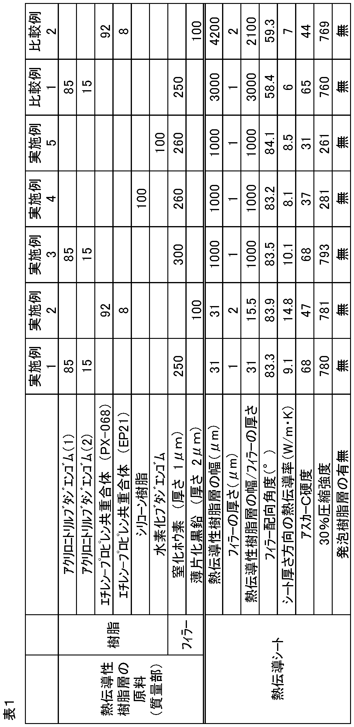
各実施例の熱伝導シートは、アスカーC硬度及び30%圧縮強度の値が低く、良好な柔軟性も有していることが確認された。
(実施例6)
アクリロニトリルブタジエンゴム(1)(JSR株式会社製「N280」、液状)85質量部、アクリロニトリルブタジエンゴム(2)(JSR株式会社製「N231L」、固体状)15質量部、厚さ1μmの窒化ホウ素300質量部を溶融混練後、プレスすることにより厚さ0.5mmの1次シートを得た。得られたシートを16等分し、16個の厚さ0.5mmの熱伝導性樹脂層を作製した。次いで、以下の方法で得られた0.5mmの発泡体シートを16等分し、16個の厚さ0.5mmの発泡樹脂層を作製した後、前記熱伝導性樹脂層と発泡樹脂層とを交互に積層して接合し、積層面に垂直な面がシート面となるように向きを調整し、発泡樹脂層と熱伝導性樹脂層とからなる熱伝導シートを得た。接合には、接着剤(スリーエム社製、6004N)を用いた。本熱伝導シートを、上記した評価方法に基づいて評価した結果を表2に示す。
(発泡体シートの作製)
アクリロニトリルブタジエンゴム(2)(JSR株式会社製「N231L」、固体状)100質量部、アゾジカルボンアミド5質量部、及びフェノール系酸化防止剤0.1質量部を溶融混練後、プレスすることにより厚さ0.15mmの発泡性樹脂シートを得た。該発泡性樹脂シートの両面に加速電圧500keVにて電子線を1.5Mrad照射して発泡性樹脂シートを架橋させた。次にシートを250℃に加熱することによって発泡性樹脂シートを発泡させて、見かけ密度0.25g/cm3、厚さ0.5mmの発泡体シートを得た。
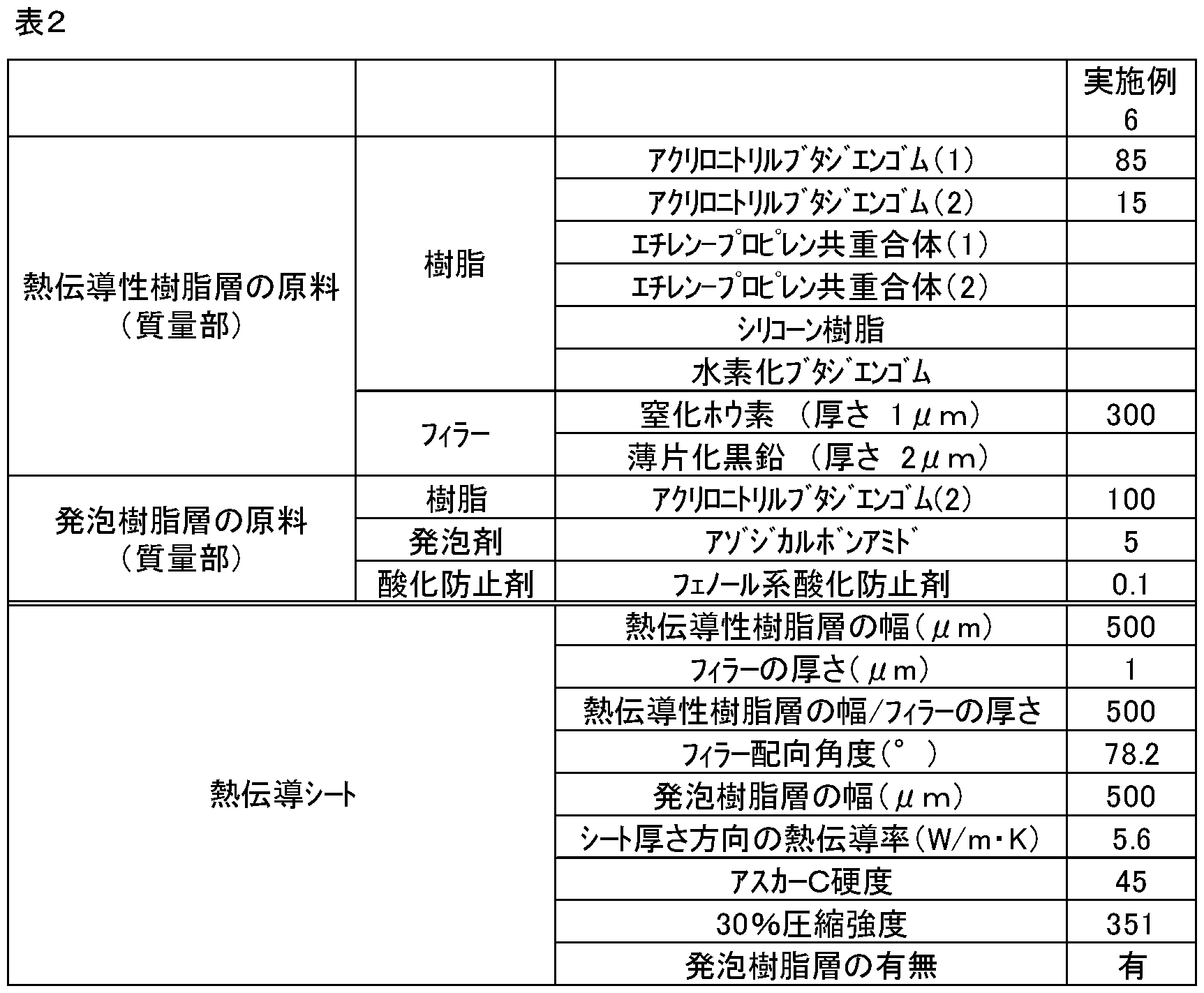
実施例6の熱伝導シートは、厚さの同じ熱伝導性樹脂層と発泡樹脂層とが交互に積層されたものであるため、熱伝導シート中の熱伝導性フィラーの体積%は、表1の比較例1の60%程度である。これにも関わらず、実施例6の熱伝導シートの熱伝導率は、比較例1とほぼ同等であり、アスカーC硬度、30%圧縮強度は、比較例1よりもはるかに低く、柔軟性に優れることが分かった。
2 樹脂層
3 発熱体
4 放熱体
5 シート面
6 熱伝導性板状フィラー
7 熱伝導性樹脂層
8 樹脂
9 非熱伝導性樹脂層
10 樹脂
11 独立気泡
12 発泡樹脂層
Claims (18)
- 熱伝導性板状フィラーを含有する熱伝導性樹脂層を含む樹脂層を複数積層した構造を有し、その積層面に対する垂直面をシート面とした熱伝導シートであって、前記熱伝導性板状フィラーの長軸が、前記シート面に対して60°以上の角度で配向している熱伝導シート。
- 前記熱伝導性樹脂層の幅が、前記熱伝導性板状フィラーの厚みの1~2000倍である、請求項1に記載の熱伝導シート。
- 前記熱伝導性板状フィラーの含有量が、前記熱伝導性樹脂層を構成する樹脂100質量部に対し、50~700質量部である請求項1又は2に記載の熱伝導シート。
- 厚み方向の熱伝導率が3W/m・K以上である、請求項1~3の何れかに記載の熱伝導シート。
- アスカーC硬度が70以下である、請求項1~4の何れかに記載の熱伝導シート。
- 30%圧縮強度が、1500kPa以下である、請求項1~5の何れかに記載の熱伝導シート。
- 前記樹脂層の全てが熱伝導性樹脂層である、請求項1~6の何れかに記載の熱伝導シート。
- 前記樹脂層として、前記熱伝導性樹脂層と熱伝導性板状フィラーを含有しない非熱伝導性樹脂層を含む、請求項1~6の何れかに記載の熱伝導シート。
- 前記非熱伝導性樹脂層が、内部に複数の気泡を含有する発泡樹脂層である、請求項8に記載の熱伝導シート。
- 前記熱伝導性樹脂層が、内部に熱伝導性板状フィラーと複数の気泡を含有する熱伝導性発泡樹脂層である、請求項1~9の何れかに記載の熱伝導シート。
- 前記樹脂層が、エチレン酢酸ビニル共重合体、ポリオレフィン系樹脂、ニトリルゴム、アクリルゴム、シリコーン樹脂、ジエン系ゴム、及び水素化ジエン系ゴムからなる群から選択された少なくとも一種を用いた樹脂層である、請求項1~10の何れかに記載の熱伝導シート。
- 前記樹脂層が、常温で液状の樹脂を含む、請求項1~11の何れかに記載の熱伝導シート。
- 前記樹脂層を構成する樹脂が、常温で液状の樹脂のみからなる、請求項1~12の何れかに記載の熱伝導シート。
- 前記熱伝導性板状フィラーが、窒化ホウ素、薄片化黒鉛の少なくとも何れかである請求項1~13の何れかに記載の熱伝導シート。
- 請求項1~14の何れかに記載の熱伝導シートの製造方法であって、前記熱伝導性樹脂層の製造方法が、樹脂と熱伝導性板状フィラーを混練して熱伝導性樹脂組成物を作製する混練工程と、前記熱伝導性樹脂組成物を積層してn層構造の積層体を作製する積層工程を含み、前記積層工程後の積層体の厚み(Dμm)、前記熱伝導性板状フィラーの厚み(dμm)が、下記式を満足する熱伝導シートの製造方法。
0.0005≦d/(D/n)≦1 - 混練工程で作製した熱伝導性樹脂組成物をxi分割して積層し、xi層構造の積層体を作製後、熱プレスを行って、厚み(Dμm)とし、その後、更に、分割と積層と前記厚みへの熱プレスを繰り替えして、前記n層構造の積層体を作製する、請求項15に記載の熱伝導シートの製造方法。
- 多層形成ブロックを備える押出機を用い、前記多層形成ブロックを調製して、共押出し成形により、前記n層構造で、かつ、前記厚さDμmの積層体を得る、請求項15に記載の熱伝導シートの製造方法。
- 前記積層工程の後に、積層方向に対して平行にスライスする工程を含む、請求項15~17の何れかに記載の熱伝導シートの製造方法。
Priority Applications (5)
| Application Number | Priority Date | Filing Date | Title |
|---|---|---|---|
| KR1020197003755A KR20190039943A (ko) | 2016-08-08 | 2017-08-08 | 열전도 시트 및 그 제조 방법 |
| US16/323,874 US20190176448A1 (en) | 2016-08-08 | 2017-08-08 | Heat transfer sheet and method for producing same |
| JP2018533515A JP6750019B2 (ja) | 2016-08-08 | 2017-08-08 | 熱伝導シート及びその製造方法 |
| EP17839499.5A EP3499561B1 (en) | 2016-08-08 | 2017-08-08 | Heat transfer sheet and method for producing same |
| CN201780049418.3A CN109729739B (zh) | 2016-08-08 | 2017-08-08 | 热传导片和其制造方法 |
Applications Claiming Priority (4)
| Application Number | Priority Date | Filing Date | Title |
|---|---|---|---|
| JP2016-155519 | 2016-08-08 | ||
| JP2016155519 | 2016-08-08 | ||
| JP2017039164 | 2017-03-02 | ||
| JP2017-039164 | 2017-03-02 |
Publications (1)
| Publication Number | Publication Date |
|---|---|
| WO2018030430A1 true WO2018030430A1 (ja) | 2018-02-15 |
Family
ID=61162300
Family Applications (1)
| Application Number | Title | Priority Date | Filing Date |
|---|---|---|---|
| PCT/JP2017/028829 Ceased WO2018030430A1 (ja) | 2016-08-08 | 2017-08-08 | 熱伝導シート及びその製造方法 |
Country Status (6)
| Country | Link |
|---|---|
| US (1) | US20190176448A1 (ja) |
| EP (1) | EP3499561B1 (ja) |
| JP (2) | JP6750019B2 (ja) |
| KR (1) | KR20190039943A (ja) |
| CN (1) | CN109729739B (ja) |
| WO (1) | WO2018030430A1 (ja) |
Cited By (13)
| Publication number | Priority date | Publication date | Assignee | Title |
|---|---|---|---|---|
| JP2020045456A (ja) * | 2018-09-20 | 2020-03-26 | 株式会社豊田中央研究所 | 熱伝導性複合材料、熱伝導性複合材料フィルム及びそれらの製造方法 |
| WO2020153377A1 (ja) * | 2019-01-22 | 2020-07-30 | 積水化学工業株式会社 | 熱伝導性樹脂シート |
| KR20210028120A (ko) | 2019-09-03 | 2021-03-11 | 신에쓰 가가꾸 고교 가부시끼가이샤 | 말레이미드 수지 필름 및 말레이미드 수지 필름용 조성물 |
| JP6978639B1 (ja) * | 2021-03-10 | 2021-12-08 | 積水化学工業株式会社 | 熱伝導性樹脂シート |
| JP2022130068A (ja) * | 2021-02-25 | 2022-09-06 | 日本ゼオン株式会社 | 複合シート及びその製造方法 |
| JP2022542444A (ja) * | 2019-07-30 | 2022-10-03 | リー,ヨンジュン | 熱界面材料 |
| WO2022249338A1 (ja) | 2021-05-26 | 2022-12-01 | 日産自動車株式会社 | 熱伝導膜およびこれを用いた放熱構造体 |
| WO2022249339A1 (ja) | 2021-05-26 | 2022-12-01 | 日産自動車株式会社 | 熱伝導膜およびこれを用いた放熱構造体 |
| JP2023016528A (ja) * | 2021-07-21 | 2023-02-02 | 日本ゼオン株式会社 | 熱伝導シート、及び熱伝導シートの製造方法 |
| US11618247B2 (en) | 2019-11-01 | 2023-04-04 | Sekisui Polymatech Co., Ltd. | Thermally conductive sheet and production method for same |
| WO2023085326A1 (ja) * | 2021-11-10 | 2023-05-19 | デンカ株式会社 | 放熱シート |
| JP2024539016A (ja) * | 2021-10-14 | 2024-10-28 | サン-ゴバン セラミックス アンド プラスティクス,インコーポレイティド | 多層複合体を形成する方法 |
| US12289864B2 (en) | 2020-03-19 | 2025-04-29 | Nitto Denko Corporation | Opto-electric transmission composite module |
Families Citing this family (3)
| Publication number | Priority date | Publication date | Assignee | Title |
|---|---|---|---|---|
| JP6988399B2 (ja) * | 2016-12-05 | 2022-01-05 | トヨタ自動車株式会社 | 車載用バッテリリレー接続構造 |
| US12595399B2 (en) * | 2020-01-22 | 2026-04-07 | 3M Innovative Properties Company | Electrically conductive adhesive layer |
| US12199253B2 (en) * | 2021-11-05 | 2025-01-14 | GM Global Technology Operations LLC | Laminated thermal barrier for anisotropic heat transfer |
Citations (8)
| Publication number | Priority date | Publication date | Assignee | Title |
|---|---|---|---|---|
| JPH1177795A (ja) * | 1997-09-12 | 1999-03-23 | Denki Kagaku Kogyo Kk | ゴムシートの製造方法 |
| JP2009066817A (ja) * | 2007-09-11 | 2009-04-02 | Nippon Valqua Ind Ltd | 熱伝導性シート |
| JP2012038763A (ja) | 2010-08-03 | 2012-02-23 | Hitachi Chem Co Ltd | 熱伝導シート、熱伝導シートの製造方法、及び熱伝導シートを用いた放熱装置 |
| JP2012109313A (ja) * | 2010-11-15 | 2012-06-07 | Hitachi Chem Co Ltd | 熱伝導シート、熱伝導シートの製造方法、及び放熱装置 |
| JP2013254880A (ja) | 2012-06-08 | 2013-12-19 | Denki Kagaku Kogyo Kk | 熱伝導性絶縁シート、金属ベース基板及び回路基板、及びその製造方法 |
| JP2014027144A (ja) * | 2012-07-27 | 2014-02-06 | Polymatech Co Ltd | 熱伝導性成形体及びその製造方法 |
| JP2014150161A (ja) * | 2013-02-01 | 2014-08-21 | Sumitomo Bakelite Co Ltd | 熱伝導シートの製造方法および熱伝導シート |
| JP2015092534A (ja) * | 2013-09-30 | 2015-05-14 | 積水化学工業株式会社 | シリコーン熱伝導性シート |
Family Cites Families (10)
| Publication number | Priority date | Publication date | Assignee | Title |
|---|---|---|---|---|
| US6794030B1 (en) * | 1999-11-30 | 2004-09-21 | 3M Innovative Properties Company | Heat conductive sheet and method of producing the sheet |
| JP4514344B2 (ja) * | 2001-02-07 | 2010-07-28 | 電気化学工業株式会社 | 熱伝導性樹脂成形体及びその用途 |
| CN101415779B (zh) * | 2006-04-07 | 2012-04-25 | 日本电气株式会社 | 导热性树脂材料及其成形体 |
| US20100073882A1 (en) * | 2006-11-01 | 2010-03-25 | Tooru Yoshikawa | Thermally conductive sheet, process for producing the same, and radiator utilizing thermally conductive sheet |
| US20110192588A1 (en) * | 2008-10-21 | 2011-08-11 | Hitachi Chemical Company, Ltd. | Heat conducting sheet, manufacturing method thereof, and heat radiator that utilizes the same |
| TW201131716A (en) * | 2010-01-29 | 2011-09-16 | Nitto Denko Corp | Thermal conductive sheet, light-emitting diode mounting substrate, and thermal conductive adhesive sheet |
| JP5423455B2 (ja) * | 2010-02-09 | 2014-02-19 | 日立化成株式会社 | 熱伝導シート、その製造方法及び熱伝導シートを用いた放熱装置 |
| WO2014083890A1 (ja) * | 2012-11-27 | 2014-06-05 | 積水化学工業株式会社 | 電子機器用熱伝導性発泡体シート及び電子機器用熱伝導性積層体 |
| JP6219624B2 (ja) * | 2013-07-04 | 2017-10-25 | デクセリアルズ株式会社 | 熱伝導シートの製造方法、熱伝導シートの製造装置、樹脂成型体の切断方法 |
| JP6347727B2 (ja) * | 2014-11-17 | 2018-06-27 | キヤノン株式会社 | 定着部材、定着装置及び画像形成装置 |
-
2017
- 2017-08-08 CN CN201780049418.3A patent/CN109729739B/zh active Active
- 2017-08-08 US US16/323,874 patent/US20190176448A1/en not_active Abandoned
- 2017-08-08 EP EP17839499.5A patent/EP3499561B1/en active Active
- 2017-08-08 KR KR1020197003755A patent/KR20190039943A/ko not_active Ceased
- 2017-08-08 WO PCT/JP2017/028829 patent/WO2018030430A1/ja not_active Ceased
- 2017-08-08 JP JP2018533515A patent/JP6750019B2/ja active Active
-
2020
- 2020-08-12 JP JP2020136208A patent/JP7168617B2/ja active Active
Patent Citations (8)
| Publication number | Priority date | Publication date | Assignee | Title |
|---|---|---|---|---|
| JPH1177795A (ja) * | 1997-09-12 | 1999-03-23 | Denki Kagaku Kogyo Kk | ゴムシートの製造方法 |
| JP2009066817A (ja) * | 2007-09-11 | 2009-04-02 | Nippon Valqua Ind Ltd | 熱伝導性シート |
| JP2012038763A (ja) | 2010-08-03 | 2012-02-23 | Hitachi Chem Co Ltd | 熱伝導シート、熱伝導シートの製造方法、及び熱伝導シートを用いた放熱装置 |
| JP2012109313A (ja) * | 2010-11-15 | 2012-06-07 | Hitachi Chem Co Ltd | 熱伝導シート、熱伝導シートの製造方法、及び放熱装置 |
| JP2013254880A (ja) | 2012-06-08 | 2013-12-19 | Denki Kagaku Kogyo Kk | 熱伝導性絶縁シート、金属ベース基板及び回路基板、及びその製造方法 |
| JP2014027144A (ja) * | 2012-07-27 | 2014-02-06 | Polymatech Co Ltd | 熱伝導性成形体及びその製造方法 |
| JP2014150161A (ja) * | 2013-02-01 | 2014-08-21 | Sumitomo Bakelite Co Ltd | 熱伝導シートの製造方法および熱伝導シート |
| JP2015092534A (ja) * | 2013-09-30 | 2015-05-14 | 積水化学工業株式会社 | シリコーン熱伝導性シート |
Non-Patent Citations (1)
| Title |
|---|
| See also references of EP3499561A4 |
Cited By (23)
| Publication number | Priority date | Publication date | Assignee | Title |
|---|---|---|---|---|
| JP2020045456A (ja) * | 2018-09-20 | 2020-03-26 | 株式会社豊田中央研究所 | 熱伝導性複合材料、熱伝導性複合材料フィルム及びそれらの製造方法 |
| JP7402410B2 (ja) | 2018-09-20 | 2023-12-21 | 株式会社豊田中央研究所 | 熱伝導性複合材料、熱伝導性複合材料フィルム及びそれらの製造方法 |
| WO2020153377A1 (ja) * | 2019-01-22 | 2020-07-30 | 積水化学工業株式会社 | 熱伝導性樹脂シート |
| JPWO2020153377A1 (ja) * | 2019-01-22 | 2021-12-02 | 積水化学工業株式会社 | 熱伝導性樹脂シート |
| JP7611895B2 (ja) | 2019-07-30 | 2025-01-10 | ヘンケル・アクチェンゲゼルシャフト・ウント・コムパニー・コマンディットゲゼルシャフト・アウフ・アクチェン | 熱界面材料 |
| JP2022542444A (ja) * | 2019-07-30 | 2022-10-03 | リー,ヨンジュン | 熱界面材料 |
| KR20210028120A (ko) | 2019-09-03 | 2021-03-11 | 신에쓰 가가꾸 고교 가부시끼가이샤 | 말레이미드 수지 필름 및 말레이미드 수지 필름용 조성물 |
| US11618247B2 (en) | 2019-11-01 | 2023-04-04 | Sekisui Polymatech Co., Ltd. | Thermally conductive sheet and production method for same |
| US12289864B2 (en) | 2020-03-19 | 2025-04-29 | Nitto Denko Corporation | Opto-electric transmission composite module |
| JP2022130068A (ja) * | 2021-02-25 | 2022-09-06 | 日本ゼオン株式会社 | 複合シート及びその製造方法 |
| JP7732196B2 (ja) | 2021-02-25 | 2025-09-02 | 日本ゼオン株式会社 | 複合シート及びその製造方法 |
| KR102802431B1 (ko) | 2021-03-10 | 2025-05-02 | 세키스이가가쿠 고교가부시키가이샤 | 열전도성 수지 시트 |
| KR20230154839A (ko) * | 2021-03-10 | 2023-11-09 | 세키스이가가쿠 고교가부시키가이샤 | 열전도성 수지 시트 |
| WO2022190293A1 (ja) * | 2021-03-10 | 2022-09-15 | 積水化学工業株式会社 | 熱伝導性樹脂シート |
| JP6978639B1 (ja) * | 2021-03-10 | 2021-12-08 | 積水化学工業株式会社 | 熱伝導性樹脂シート |
| WO2022249339A1 (ja) | 2021-05-26 | 2022-12-01 | 日産自動車株式会社 | 熱伝導膜およびこれを用いた放熱構造体 |
| US12595979B2 (en) | 2021-05-26 | 2026-04-07 | Nissan Motor Co., Ltd. | Heat conduction film and heat-dissipating structure using same |
| WO2022249338A1 (ja) | 2021-05-26 | 2022-12-01 | 日産自動車株式会社 | 熱伝導膜およびこれを用いた放熱構造体 |
| JP2023016528A (ja) * | 2021-07-21 | 2023-02-02 | 日本ゼオン株式会社 | 熱伝導シート、及び熱伝導シートの製造方法 |
| JP2024539016A (ja) * | 2021-10-14 | 2024-10-28 | サン-ゴバン セラミックス アンド プラスティクス,インコーポレイティド | 多層複合体を形成する方法 |
| JP7738752B2 (ja) | 2021-10-14 | 2025-09-12 | サン-ゴバン セラミックス アンド プラスティクス,インコーポレイティド | 多層複合体を形成する方法 |
| JP7293522B1 (ja) * | 2021-11-10 | 2023-06-19 | デンカ株式会社 | 放熱シート |
| WO2023085326A1 (ja) * | 2021-11-10 | 2023-05-19 | デンカ株式会社 | 放熱シート |
Also Published As
| Publication number | Publication date |
|---|---|
| KR20190039943A (ko) | 2019-04-16 |
| JP7168617B2 (ja) | 2022-11-09 |
| EP3499561B1 (en) | 2024-05-08 |
| CN109729739B (zh) | 2023-04-18 |
| CN109729739A (zh) | 2019-05-07 |
| EP3499561A4 (en) | 2020-04-15 |
| US20190176448A1 (en) | 2019-06-13 |
| JP2020205426A (ja) | 2020-12-24 |
| JPWO2018030430A1 (ja) | 2019-03-22 |
| EP3499561A1 (en) | 2019-06-19 |
| JP6750019B2 (ja) | 2020-09-02 |
Similar Documents
| Publication | Publication Date | Title |
|---|---|---|
| JP7168617B2 (ja) | 熱伝導シート及びその製造方法 | |
| JP6505874B2 (ja) | 熱伝導シート | |
| CN110945647B (zh) | 导热片 | |
| JP5541400B2 (ja) | 熱伝導性シートの製造方法 | |
| KR102558979B1 (ko) | 열전도성 시트 | |
| JP2020196892A (ja) | 熱伝導シート | |
| JP2017034219A (ja) | 混合グラファイトを用いた放熱材 | |
| JP6978639B1 (ja) | 熱伝導性樹脂シート | |
| JP6989675B1 (ja) | 熱伝導性シート及び熱伝導性シートの製造方法 | |
| CN113337253A (zh) | 导热垫片及其制备方法 | |
| JP7542317B2 (ja) | 熱伝導性樹脂シート | |
| JP2018098349A (ja) | 熱伝導シート、熱伝導シートの製造方法及び放熱装置 | |
| JP2021054876A (ja) | 熱伝導シート | |
| JP2022064582A (ja) | 熱伝導シート、電子機器及び車載装置 | |
| JP7732196B2 (ja) | 複合シート及びその製造方法 | |
| JP2019214663A (ja) | 熱伝導性シート |
Legal Events
| Date | Code | Title | Description |
|---|---|---|---|
| ENP | Entry into the national phase |
Ref document number: 2018533515 Country of ref document: JP Kind code of ref document: A |
|
| 121 | Ep: the epo has been informed by wipo that ep was designated in this application |
Ref document number: 17839499 Country of ref document: EP Kind code of ref document: A1 |
|
| ENP | Entry into the national phase |
Ref document number: 20197003755 Country of ref document: KR Kind code of ref document: A |
|
| NENP | Non-entry into the national phase |
Ref country code: DE |
|
| ENP | Entry into the national phase |
Ref document number: 2017839499 Country of ref document: EP Effective date: 20190311 |