WO2018034112A1 - ピストンリング - Google Patents
ピストンリング Download PDFInfo
- Publication number
- WO2018034112A1 WO2018034112A1 PCT/JP2017/026804 JP2017026804W WO2018034112A1 WO 2018034112 A1 WO2018034112 A1 WO 2018034112A1 JP 2017026804 W JP2017026804 W JP 2017026804W WO 2018034112 A1 WO2018034112 A1 WO 2018034112A1
- Authority
- WO
- WIPO (PCT)
- Prior art keywords
- facing
- male
- peripheral surface
- piston ring
- outer peripheral
- Prior art date
- Legal status (The legal status is an assumption and is not a legal conclusion. Google has not performed a legal analysis and makes no representation as to the accuracy of the status listed.)
- Ceased
Links
Images


Classifications
-
- F—MECHANICAL ENGINEERING; LIGHTING; HEATING; WEAPONS; BLASTING
- F16—ENGINEERING ELEMENTS AND UNITS; GENERAL MEASURES FOR PRODUCING AND MAINTAINING EFFECTIVE FUNCTIONING OF MACHINES OR INSTALLATIONS; THERMAL INSULATION IN GENERAL
- F16J—PISTONS; CYLINDERS; SEALINGS
- F16J9/00—Piston-rings, e.g. non-metallic piston-rings, seats therefor; Ring sealings of similar construction
- F16J9/12—Details
- F16J9/14—Joint-closures
- F16J9/16—Joint-closures obtained by stacking of rings
-
- F—MECHANICAL ENGINEERING; LIGHTING; HEATING; WEAPONS; BLASTING
- F02—COMBUSTION ENGINES; HOT-GAS OR COMBUSTION-PRODUCT ENGINE PLANTS
- F02F—CYLINDERS, PISTONS OR CASINGS, FOR COMBUSTION ENGINES; ARRANGEMENTS OF SEALINGS IN COMBUSTION ENGINES
- F02F5/00—Piston rings, e.g. associated with piston crown
Definitions
- the present invention relates to a piston ring used in an internal combustion engine.
- Piston rings used in automobile internal combustion engines and the like are provided, for example, in a ring groove on the piston outer peripheral surface. Since the outer peripheral surface of the piston ring is in sliding contact with the inner peripheral surface of the bore and one side surface of the piston ring is in contact with the side surface of the ring groove, a function of preventing blow-by gas from the combustion chamber side to the crank chamber side is achieved. Since such a piston ring has a split ring shape having an abutment portion for the convenience of mounting in the ring groove, there is a problem of suppressing blow-by gas at the abutment portion.
- the piston ring described in Patent Document 1 discloses a piston ring having a special joint structure.
- one abutment end portion is provided with a protruding portion extending in the circumferential direction while forming a wedge shape whose cross section is narrowed radially inward.
- the other abutment end portion is provided with a recess serving as a receiving portion for the protruding portion.
- the sealing property of the blow-by gas is improved by ensuring the degree of adhesion between the mating surfaces of the protrusion and the recess.
- the piston ring when the piston ring is mounted in the ring groove on the outer peripheral surface of the piston, the piston ring is mounted in the ring groove by expanding the inner diameter of the ring beyond the outer diameter of the piston.
- the piston to which the piston ring is attached is inserted into the cylinder block in the engine assembly process.
- An object of the present invention is to provide a piston ring that can prevent breakage of the joint portion and can ensure good sealing performance.
- a piston ring is a piston ring including an annular main body portion having an inner peripheral surface and an outer peripheral surface facing each other, and a joint portion formed in the main body portion.
- a first projecting portion projecting from one abutment end portion toward the other abutment end portion, and a first receiving portion receiving the first projecting portion at the other abutment end portion;
- a second projection that projects from the other abutment end toward the one abutment end, and a second projection that receives the second projection at the one abutment end.
- a first male portion projecting from the second projecting portion toward the second receiving portion, and the first receiving portion in the second receiving portion.
- a first female part that receives the male part of the main body part is provided on the outer peripheral surface side of the main body part.
- a second male part projecting toward the first receiving part and a second female part receiving the second male part in the first receiving part are provided, and the first male part is the first male part.
- the second male part has an inclined surface or a convex curved surface that is inclined with respect to the mating surface with respect to the first female part and faces the outer peripheral surface side so that the tip of the male part is tapered.
- the second male portion has an inclined surface or a convex curved surface that is inclined with respect to the mating surface with respect to the second female portion and faces the inner peripheral surface side so that the tip of the second male portion is tapered.
- the tips of the first male part and the second male part are both tapered.
- the inclined surface or convex curved surface facing the outer peripheral surface side of the first male portion and the inclined surface or convex curved surface facing the inner peripheral surface side of the second male portion are a piston ring.
- cranks are formed by shifting each other.
- a position where the first male part and the first female part are opposed to each other on the inner peripheral surface side of the main body part, and a position where the second male part and the second female part are opposed to each other on the outer peripheral surface side of the main body part. Are shifted from each other, so that a crank different from the crank is formed.
- the first male part may have an inclined surface facing the outer peripheral surface side
- the second male part may have an inclined surface facing the inner peripheral surface side.
- the first male part may have a convex curved surface facing the outer peripheral surface side
- the second male part may have a convex curved surface facing the inner peripheral surface side. In this case, the catch of the first male part and the second male part can be satisfactorily suppressed.
- the first male part is a mating surface for the first female part, has a tip surface extending perpendicularly to the circumferential direction
- the second male part is a mating surface for the second female part.
- the distal ends of the first male part and the second male part have a thickness corresponding to the distal end surface. For this reason, the intensity
- a first facing surface facing an inclined surface or a convex curved surface facing the outer peripheral surface of the first male portion is formed in the first corner formed by the first female portion and the second male portion. Is provided at the second corner formed by the second female portion and the first male portion on an inclined surface or a convex curved surface facing the inner peripheral surface of the second male portion.
- a second opposing surface is provided, the first opposing surface is a concave curved surface or plane facing the inner peripheral surface side, and the second opposing surface is a concave curved surface facing the outer peripheral surface side. It may be a plane or a plane.
- the gap between the inclined surface or the curved surface of the first male portion and the first opposing surface, the inclined surface or the curved surface of the second male portion, and the second opposing surface Can be narrowed. Thereby, accumulation of sludge etc. in the gap can be suppressed.
- the first opposing surface may be a concave curved surface facing the inner peripheral surface side
- the second opposing surface may be a concave curved surface facing the outer peripheral surface side.
- the first facing surface may be a plane facing the inner peripheral surface side
- the second facing surface may be a plane facing the outer peripheral surface side
- a piston ring according to another aspect of the present invention is a piston ring including an annular main body portion having an inner peripheral surface and an outer peripheral surface facing each other, and a joint portion formed in the main body portion.
- the first projecting portion projecting from one abutment end portion toward the other abutment end portion and the first receiving portion receiving the first projecting portion at the other abutment end portion are provided on one side of the main body portion.
- a second receiving portion is provided, and on the outer peripheral surface side of the main body portion, a first male portion protruding from the second protruding portion toward the second receiving portion, and a second receiving portion at the second receiving portion
- a first female part that receives one male part, and a first protrusion on the inner peripheral surface side of the main body part
- the second male part has an inclined surface or a convex curved surface that is inclined with respect to the mating surface with respect to the first female part and faces the inner peripheral surface side so that the tip of the male part is tapered.
- the tips of the first male part and the second male part are both tapered.
- the inclined surface or convex curved surface facing the inner peripheral surface side of the first male part and the inclined surface or convex curved surface facing the outer peripheral surface side of the second male part are a piston ring.
- cranks are formed by shifting each other.
- a position where the first male part and the first female part face each other on the outer peripheral surface side of the main body part, and a position where the second male part and the second female part face each other on the inner peripheral surface side of the main body part. Are shifted from each other, so that a crank different from the crank is formed.
- the first male part may have an inclined surface facing the inner peripheral surface side
- the second male part may have an inclined surface facing the outer peripheral surface side.
- the first male part may have a convex curved surface facing the inner peripheral surface side
- the second male part may have a convex curved surface facing the outer peripheral surface side. In this case, the catch of the first male part and the second male part can be satisfactorily suppressed.
- the first male part is a mating surface for the first female part, has a tip surface extending perpendicularly to the circumferential direction
- the second male part is a mating surface for the second female part.
- the distal ends of the first male part and the second male part have a thickness corresponding to the distal end surface. For this reason, the intensity
- the first opposing part faces the inclined surface or convex curved surface facing the inner peripheral surface of the first male part.
- the second female corner and the first male part are formed on an inclined surface or a convex curved surface facing the outer peripheral surface of the second male part.
- a second opposing surface is provided, the first opposing surface being a concave curved surface or plane facing the outer peripheral surface side, and the second opposing surface being a concave curved surface facing the inner peripheral surface side. It may be a plane or a plane.
- the gap between the inclined surface or the curved surface of the first male portion and the first opposing surface, the inclined surface or the curved surface of the second male portion, and the second opposing surface. Can be narrowed. Thereby, accumulation of sludge etc. in the gap can be suppressed.
- the first opposing surface may be a concave curved surface facing the outer peripheral surface side
- the second opposing surface may be a concave curved surface facing the inner peripheral surface side
- the first facing surface may be a plane facing the outer peripheral surface side
- the second facing surface may be a plane facing the inner peripheral surface side
- a surface treatment film may be provided on at least one of the mating surface, the inclined surface, and the convex curved surface with respect to the female portion. In this case, the main body can be protected by the surface treatment film.
- the main body may be made of metal or alloy. Thereby, sufficient heat resistance of the piston ring can be ensured.
- the main body may be formed of a heat-resistant resin composition. Thereby, a joint part can be processed easily, ensuring the heat resistance of a piston ring.
- the resin composition may contain a filler for improving heat resistance. Thereby, sufficient heat resistance of the piston ring can be ensured.
- the piston ring According to the piston ring according to one aspect of the present invention, it is possible to suppress breakage of the abutment portion and to ensure good sealing performance.
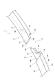
- FIG. 1 is a perspective view showing a first embodiment of a piston ring according to an aspect of the present invention.
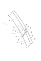
- FIG. 2 is an enlarged perspective view of a main part of the joint portion of the piston ring shown in FIG.
- FIG. 3 is an enlarged perspective view of a main part showing a joint portion of the piston ring shown in FIG. 1 from one side surface side.
- FIG. 4 is an enlarged perspective view of a main part showing the joint portion of the piston ring shown in FIG. 1 from the other side surface side.
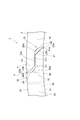
- FIG. 5 is an enlarged view of a main part when the joint portion of the piston ring shown in FIG. 1 is viewed from the other side surface.
- FIG. 2 is an enlarged perspective view of a main part of the joint portion of the piston ring shown in FIG.
- FIG. 3 is an enlarged perspective view of a main part showing a joint portion of the piston ring shown in FIG. 1 from one side surface side.
- FIG. 4 is an enlarged perspective view of a main part showing the joint
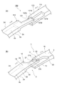
- FIG. 6A is an enlarged perspective view of a main part showing a reduced diameter of the piston ring according to the comparative example
- FIG. 6B is a main part showing a reduced diameter of the piston ring according to the first embodiment.
- FIG. 7A is an enlarged view of the main part of the piston ring joint in a free state as viewed from the outer peripheral surface side
- FIG. 7B shows the piston ring joint after assembly to the piston on the outer peripheral surface. It is the principal part enlarged view seen from the side.
- FIG. 8 is an enlarged view of a main part when a joint portion of a piston ring according to a modification of the first embodiment is viewed from the other side surface.
- FIG.9 (a) is the principal part enlarged view which looked at the joint part of the piston ring of 2nd Embodiment from the other side surface
- FIG.9 (b) is the joint of the piston ring of the modification of 2nd Embodiment. It is the principal part enlarged view which looked at the part from the other side surface side.
- FIG. 1 is a perspective view showing a first embodiment of a piston ring according to an aspect of the present invention.
- a piston ring 1 shown in the figure is provided in a ring groove on an outer peripheral surface of a piston in an internal combustion engine of an automobile, for example.
- the blow-by gas from the combustion chamber side to the crank chamber side is obtained when the outer peripheral surface 2d of the piston ring 1 is in sliding contact with the inner peripheral surface of the bore and the side surface 2b of the piston ring 1 is in contact with the side surface of the ring groove to form a seal surface
- the function of preventing this is achieved.
- the piston ring 1 includes an annular main body 2 and a joint portion 3 formed in a part of the main body 2.
- the main body 2 has a long side in the thickness direction by a side surface 2a (one side surface) and a side surface 2b (other side surface) which are end surfaces in the width direction, and an inner peripheral surface 2c and an outer peripheral surface 2d which are end surfaces in the thickness direction.
- the cross section has a substantially rectangular shape with a short side in the width direction.
- the main body 2 is formed of a metal or an alloy (a cast iron or steel material containing a plurality of metal elements) with sufficient strength, heat resistance, and elasticity.
- a surface treatment film is provided on the surface of the main body 2.
- the surface treatment film is, for example, a hard film such as a hard chromium plating layer, a PVD treatment layer, a nitride layer such as iron or chromium, or a DLC (diamond-like carbon) film.
- a hard film such as a hard chromium plating layer, a PVD treatment layer, a nitride layer such as iron or chromium, or a DLC (diamond-like carbon) film.
- FIGS. 2 to 4 is an enlarged perspective view of a main part showing the joint portion 3 of the piston ring 1 shown in FIG. 1 from the side surface 2a.
- the abutment portion 3 is a cut formed in a part of the main body portion 2 for the purpose of securing the mountability when the piston ring 1 is mounted in the ring groove on the piston outer peripheral surface. Is provided.
- one abutment end portion 11 and the other abutment end portion 12 face each other with a predetermined interval before the piston ring 1 is mounted in the ring groove.
- a first projecting portion projecting from one joint end portion 11 toward the other joint end portion 12 on the side surface 2a side of the main body 2 is provided.
- 13 and a first receiving portion 14 that receives the first protruding portion 13 at the other joint end portion 12 are provided.
- a second projecting portion 15 projecting from the other joint end portion 12 toward the one joint end portion 11, and a second projecting portion at the one joint end portion 11. 15 and a second receiving portion 16 that receives 15 is provided on the side surface 2 b side of the main body 2.
- a substantially half portion on the side surface 2 a side of the main body 2 is projected from the one end portion 11 in a substantially rectangular shape. Further, in the first projecting portion 13, the tip angle on the side surface 2 b facing the first receiving portion 14 is notched. As a result, a notch surface S1 is formed at the tip of the first protrusion 13 on the side of the side surface 2b facing the first receiving portion 14.
- a state in which a substantially half portion on the side surface 2 a side of the main body portion 2 is cut out into a substantially rectangular cross section corresponding to the shape of the first protruding portion 13 in the other joint end portion 12. It has become.
- a front end surface 13a that is a surface facing the first receiving portion 14 in the first protrusion 13 and a front end surface 14a that is a surface facing the first protruding portion 13 in the first receiving portion 14 are respectively in the circumferential direction. On the other hand, it has a substantially rectangular shape extending vertically or substantially vertically.
- the substantially half part by the side surface 2b side of the main-body part 2 is in the state which protruded in cross-sectional substantially rectangular shape from the other abutment edge part 12.
- the tip angle on the side surface 2 a facing the second receiving portion 16 is notched.
- a notch surface S ⁇ b> 2 is formed at the tip on the side surface 2 a facing the second receiving portion 16 in the second protrusion 15.
- a first male part 21 projecting from the second projecting part 15 toward the second receiving part 16;
- Two receiving portions 16 are provided with a first female portion 22 that receives the first male portion 21.
- a second male portion 23 that protrudes from the second receiving portion 16 toward the second protrusion portion 15, and a second A second female portion 24 that receives the second male portion 23 is provided in the protruding portion 15.
- a so-called step joint is formed by the first male part 21, the first female part 22, the second male part 23, and the second female part 24.
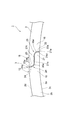
- FIG. 5 is an enlarged view of a main part of the joint portion 3 as viewed from the side surface 2b.
- the first male portion 21 is in a state in which a substantially half portion of the second protruding portion 15 on the inner peripheral surface 2 c side protrudes.
- the first male portion 21 is inclined with respect to the mating surface 21a so that the mating surface 21a with respect to the first female portion 22 and the tip of the first male portion 21 are tapered, and And an inclined surface 21b facing the outer peripheral surface 2d side.
- the mating surface 21a is a distal end surface that is positioned on the inner peripheral surface 2c side of the first male portion 21 with respect to the inclined surface 21b and extends perpendicular to the circumferential direction.
- One end of the mating surface 21a and the inner peripheral surface 2c form a right angle.
- the inclined surface 21b is a plane connected to the end of the mating surface 21a on the outer peripheral surface 2d side, and is formed, for example, by cutting out a corner on the outer peripheral surface 2d side of the first male portion 21.
- the mating surface 21a and the inclined surface 21b form an obtuse angle.
- the angle formed by the mating surface 21a and the inclined surface 21b is, for example, 110 ° or more or 120 ° or more, and is 170 ° or less, 160 ° or less, or 150 ° or less.
- the proportion of the inclined surface 21b is, for example, 0.1 times or more, 0.2 times or more, or 0.5 times or more of the proportion of the mating surface 21a, 100 times or less, 50 times or less, or 35 times or less.
- the second male part 23 is in a state in which a substantially half part on the outer peripheral surface 2d side of the second receiving part 16 protrudes.
- the second male portion 23 is inclined with respect to the mating surface 23a so that the mating surface 23a with respect to the second female portion 24 and the tip of the second male portion 23 are tapered, and And an inclined surface 23b facing the inner peripheral surface 2c.
- the mating surface 23a is a distal end surface that is positioned on the distal end side of the second male portion 23 and on the outer circumferential surface 2d side with respect to the inclined surface 23b, and extends perpendicular to the circumferential direction.
- One end of the mating surface 23a and the outer peripheral surface 2d form a right angle.
- the inclined surface 23b is a plane connected to the end on the inner peripheral surface 2c side of the mating surface 23a, and is formed by cutting out a corner portion on the inner peripheral surface 2c side in the second male portion 23, for example.
- the mating surface 23a and the inclined surface 23b form an obtuse angle.
- the angle formed by the mating surface 23a and the inclined surface 23b is, for example, 110 or more or 120 ° or more, and is 170 ° or less, 160 ° or less, or 150 ° or less.
- the proportion of the inclined surface 23b is, for example, 0.1 times or more, 0.2 times or more, or 0.5 times or more of the proportion of the mating surface 23a, 100 times or less, 50 times or less, or 35 times or less.
- the first female portion 22 is in a state in which a substantially half portion on the inner peripheral surface 2c side of the second receiving portion 16 is cut out so as not to contact the first male portion 21.
- a first entry corner 25 formed by the first female part 22 and the second male part 23 is provided with a facing surface 25a (first facing surface) that faces the inclined surface 21b.
- the facing surface 25 a forms a concave curved surface facing the inner peripheral surface 2 c, the mating surface 23 c of the second male part 23 with respect to the first male part 21, and the first female part 22 first.
- the mating surface 22a with respect to the male part 21 is smoothly connected.
- the second female part 24 is in a state where a substantially half part on the outer peripheral surface 2d side of the second projecting part 15 is cut out so as not to contact the second male part 23.
- the second corner portion 26 formed by the second female portion 24 and the first male portion 21 is provided with a facing surface 26a (second facing surface) that faces the inclined surface 23b.
- the facing surface 26 a forms a concave curved surface facing the outer peripheral surface 2 d side, the mating surface 21 c of the first male portion 21 with respect to the second male portion 23, and the second female portion 24.
- the mating surface 24a with respect to the male part 23 is smoothly connected.
- the base end side of the 1st male part 21 which makes the 2nd inside corner part 26 is thicker than the front end side of the 1st male part 21, the base end side of the 1st male part 21 Strength against breakage (breakage strength) is increasing.
- FIG. 6A is an enlarged perspective view of a main part showing a reduced diameter of the piston ring according to the comparative example
- FIG. 6B is a main view showing a reduced diameter of the piston ring 1 according to the first embodiment.
- the piston inner ring is attached to the ring groove by expanding the inner diameter of the ring beyond the outer diameter of the piston.
- the piston to which the piston ring is attached is inserted into the cylinder block in the engine assembly process.
- the piston ring is reduced in diameter to the cylinder inner diameter so as not to prevent the piston ring from being inserted into the cylinder block.
- the diameter reduction of a piston ring is implemented using jigs, such as a taper cone, for example.
- the first male part 121 does not have the inclined surface 21b, and the second male part 123 has the inclined surface 23b. Does not have.
- the corner 121d is provided at the tip of the first male part 121 on the outer peripheral surface 2d side, and the corner 123d is provided at the tip of the second male part 123 on the inner peripheral surface 2c side. Yes.
- the corner portion 121d of the first male portion 121 collides with the tip surface 123a of the second male portion 123, and the corner portion 121d.
- the tips of the first male part 21 and the second male part 23 are both tapered.
- the inclined surface 21 b of the first male part 21 and the inclined surface 23 b of the second male part 23 are provided so as to face each other in the thickness direction of the piston ring 1.
- the inclined surfaces 21b and 23b since the inclined surfaces 21b and 23b not provided with the corners collide with each other, the first male part 21 and the second male part 23 are not easily caught. In addition, since the inclined surfaces 21b and 23b are in surface contact with each other at the time of the collision, stress concentration is less likely to occur. Therefore, the breakage of the joint portion 3 can be satisfactorily suppressed. Furthermore, the inclined surfaces 21b and 23b slide according to the force applied when the diameter of the piston ring 1 is reduced, and the piston ring 1 can be easily closed.
- crank C ⁇ b> 1 is formed by the mating surface 23 a, the inclined surface 23 b, and the mating surface 24 a of the second female portion 24.
- the mating surface 21c of the first male portion 21 with respect to the second male portion 23 and the mating surface 23c of the second male portion 23 with respect to the first male portion 21 are in use when the piston ring 1 is used. Less susceptible to temperature expansion. Further, even when a load due to the vertical movement of the piston is applied to the piston ring 1, the load is hardly applied in the facing direction of the mating surfaces 21c and 23c, and the influence of wear is small, so the interval between the mating surfaces 21c and 23c is kept small. be able to. Therefore, it is possible to minimize the gas flow area in the crank C1, and it is possible to suppress the gas that has circulated to the inner peripheral surface 2c side of the piston ring 1 from passing through the crank C1 to the outer peripheral surface 2d side. .
- FIG. 7A is an enlarged view of the main part of the joint portion 3 of the piston ring 1 in the free state as viewed from the outer peripheral surface 2d side
- FIG. 7B is the joint portion of the piston ring 1 after being assembled to the piston. It is the principal part enlarged view which looked at the part 3 from the outer peripheral surface 2d side.
- FIG. 7 (b) when the piston ring 1 is mounted in the ring groove on the outer peripheral surface of the piston, the first projecting portion 13 and the first receiving portion 14 are opposed to each other on the side surface 2a side of the main body portion 2.
- the first male part 21 is a mating surface 21a with respect to the first female part 22 and has a distal end surface extending perpendicularly to the circumferential direction
- the second male part 23 is a second female part.
- 24 is a mating surface 23a, and has a front end surface extending perpendicularly to the circumferential direction.
- tip of the 1st male part 21 and the 2nd male part 23 has the thickness corresponded to the mating surfaces 21a and 23a mutually.
- tip of the 1st male part 21 and the 2nd male part 23 can be ensured, and the damage of the joint part 3 can be suppressed favorably.
- the first corner portion 25 formed by the first female portion 22 and the second male portion 23 is provided with a facing surface 25a facing the inclined surface 21b of the first male portion 21, and the second
- the second inner corner portion 26 formed by the female portion 24 and the first male portion 21 is provided with a facing surface 26a facing the inclined surface 23b of the second male portion 23, and the facing surface 25a is
- the concave curved surface facing the inner peripheral surface 2c side and the opposing surface 26a may be a concave curved surface facing the outer peripheral surface 2d side.
- the clearance gap between the inclined surface 21b and the opposing surface 25a which the 1st male part 21 has, and the clearance gap between the inclined surface 23b and the opposing surface 26a which the 2nd male part 23 has can be narrowed. Thereby, accumulation of sludge etc. in the gap can be suppressed.
- a surface treatment film may be provided on at least one of the side surfaces 2a, 2b, the inner peripheral surface 2c, and the outer peripheral surface 2d. In this case, the main body 2 can be protected by the surface treatment film.
- the main body 2 may be formed of a metal or an alloy. Thereby, sufficient heat resistance of the piston ring 1 can be ensured.
- the 1st male part 21 has the inclined surface 21b, for example, as shown in FIG. 8, in a modification, the 1st male part 21 is with respect to the mating surface 21a. And may have a convex curved surface 21d that is inclined and faces the outer peripheral surface 2d side. Similarly, in the modification, the second male portion 23 may have a convex curved surface 23d that is inclined with respect to the mating surface 23a and faces the inner peripheral surface 2c instead of the inclined surface 23b. Good.
- the first male portion 21 and the second male portion 23 can be easily caught when the piston ring 1 is mounted in the ring groove on the piston outer peripheral surface. Can be suppressed.
- the gap between the curved surface 21d of the first male part 21 and the facing surface 25a of the first corner 25 can be further reduced, and the second male part Since the gap between the curved surface 23d of 23 and the facing surface 26a of the second corner 26 can be further narrowed, accumulation of sludge and the like in the gap can be satisfactorily suppressed.
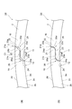
- FIG. 9A is an enlarged view of a main part of the joint portion of the piston ring according to the second embodiment as viewed from the other side surface.
- the piston ring 1 ⁇ / b> A shown in FIG. 9 (a) has the first male part 21, the first female part 22, the second male part 23, and the position where the second female part 24 is provided. It differs from the piston ring 1 of one embodiment. Specifically, on the side surface 2b side of the main body portion 2, on the outer peripheral surface 2d side of the main body portion 2, a first male portion 21 protruding from the second protrusion portion 15 toward the second receiving portion 16 and In the second receiving part 16, a first female part 22 that receives the first male part 21 is provided.
- a second male part 23 protruding from the second receiving part 16 toward the second protruding part 15;
- a second female portion 24 that receives the second male portion 23 is provided in the two protruding portions 15.
- the first male portion 21 in the piston ring 1A has an inclined surface 21b that is inclined with respect to the mating surface 22a with respect to the first female portion 22 and directed toward the inner peripheral surface 2c so that the tip thereof is tapered. is doing.
- the second male portion 23 has an inclined surface 23b that is inclined with respect to the mating surface 24a with respect to the second female portion 24 and directed toward the outer peripheral surface 2d so that the tip thereof is tapered.
- the facing surface 25a provided in the first corner portion 25 formed by the first female portion 22 and the second male portion 23 forms a concave curved surface facing the outer peripheral surface 2d side.
- the opposing surface 26a provided in the second corner 26 formed by the two female portions 24 and the first male portion 21 forms a concave curved surface facing the inner peripheral surface 2c.
- FIG. 9B is an enlarged view of a main part when the joint portion of the piston ring of the modified example of the second embodiment is viewed from the other side surface.
- the first male part 21 of the modification shown in FIG. 9B may have a convex curved surface 21d that is inclined with respect to the mating surface 21a and faces the inner peripheral surface 2c.
- the second male portion 23 may have a convex curved surface 23d that is inclined with respect to the mating surface 23a and faces the outer peripheral surface 2d, instead of the inclined surface 23b. .
- the present invention is not limited to the first and second embodiments.
- the main body 2 is formed of a metal or an alloy.
- the piston ring is made of a resin composition such as a synthetic resin.
- One main body 2 may be formed.
- the piston ring 1 may be formed of a resin composition having heat resistance.
- the resin composition having heat resistance is, for example, polyimide (PI), polyamideimide (PAI), polytetrafluoroethylene (PTFE), polybenzimidazole (PBI), polyetherketoneketone (PEEK), polyetherketone.
- the resin composition may contain a filler for improving heat resistance. Thereby, sufficient heat resistance of the piston ring 1 can be ensured.
- the facing surface 25a of the first corner 25 is a concave curved surface facing the inner peripheral surface 2c, but is not limited thereto.
- the facing surface 25a may be a flat surface facing the inner peripheral surface 2c.
- the opposing surface 25 a is an inclined surface that is inclined with respect to the mating surface 22 a of the first female portion 22 with respect to the first male portion 21, and the mating surface 22 a and the first of the second male portion 23.
- the mating surface 23c with respect to the male part 21 is connected.
- the facing surface 26a of the second corner 26 may be a flat surface facing the outer peripheral surface 2d side.
- the facing surface 26 a is an inclined surface that is inclined with respect to the mating surface 24 a with respect to the second male portion 23 of the second female portion 24, and the mating surface 24 a and the second of the first male portion 21.
- the mating surface 21c with respect to the male part 23 is connected.
- the facing surface 25a may be a flat surface facing the outer peripheral surface 2d
- the facing surface 26a may be a flat surface facing the inner peripheral surface 2c.
- the 1st male part 21 has the inclined surface 21b and the 2nd male part 23 has the inclined surface 23b, it is not restricted to this.
- the first male part 21 may have an inclined surface 21b, while the second male part 23 may have a convex curved surface 23d.
- the first male part 21 may have a convex curved surface 21d, while the second male part 23 may have an inclined surface 23b.
- the facing surface 25a of the first corner portion 25 is a concave curved surface facing the inner peripheral surface 2c side, and the facing surface 26a of the second corner portion 26 faces the outer peripheral surface 2d side.
- the concave curved surface which faces it is not restricted to this.
- the opposing surface 25a of the first corner 25 is a concave curved surface facing the inner circumferential surface 2c, while the facing surface 26a of the second corner 26 is a plane facing the outer circumferential surface 2d. Good.
- the opposing surface 25a of the first corner 25 is a flat surface facing the inner circumferential surface 2c
- the facing surface 26a of the second corner 26 is a concave curved surface facing the outer circumferential surface 2d.
- the opposing surface 25a is a concave curved surface which faces the outer peripheral surface 2d side
- the opposing surface 26a may be a plane which faces the inner peripheral surface 2c side
- the opposing surface 25a is an outer peripheral surface.
- the facing surface 26a may be a concave curved surface facing the inner peripheral surface 2c side.
- the mating surface 21a is a tip surface that extends perpendicular to the circumferential direction, but is not limited thereto.
- the mating surface 21a may be an inclined surface that forms an acute angle with the inclined surface 21b, or may be a part of the curved surface 21d.
- the mating surface 23a may be an inclined surface that forms an acute angle with the inclined surface 23b, or may be a part of the curved surface 23d.
- the surface of the main body 2 is the side surfaces 2a and 2b, the inner peripheral surface 2c, and the outer peripheral surface 2d, but is not limited thereto.
- the surface of the main body part 2 may include each surface constituting the joint part 3.
- the front surfaces 13a, 14a, 15a, and 16a, the mating surfaces 13b, 15b, 21a, 21c, 22a, 23a, 23c, and 24a, the inclined surfaces 21b and 23b, and the curved surface 21d are referred to as the surfaces that constitute the joint portion 3. , 23d, opposed surfaces 25a, 26a, and cutout surfaces S1, S2.
- a surface treatment film may be provided on at least one of the surfaces constituting the joint portion 3. In this case, it is possible to satisfactorily suppress the breakage of the main body 2 constituting the joint portion 3.
- the side surface 2a is disposed on the combustion chamber side of the piston, and the side surface 2b is disposed on the crank chamber side of the piston. Also good.
- the mating surface 21c of the first male part 21 with respect to the second male part 23 and the mating surface 23c of the second male part 23 with respect to the first male part 21 are not easily affected by temperature expansion, and the piston The influence of wear during use of the ring 1 is also reduced. For this reason, the space
- the side surface 2a is disposed on the crank chamber side of the piston, and the side surface 2b is disposed on the combustion chamber side of the piston. Also good. In this case, oil consumption can be satisfactorily suppressed by the piston ring 1, so that oil consumption can be reduced.
- the piston ring 1 has a substantially rectangular cross section, but is not limited thereto.
- the cross-sectional shape of the piston ring 1 may have a keystone shape, a tapered shape, or a barrel face shape.
- convex curve Surface 22 ... first female part, 23 ... second male part, 23a ... mating surface (tip face), 23b ... inclined surface, 23d ... convex curved surface, 24 ... second female part, 25 ... First entrance corner, 25a ... opposing surface (first opposing surface), 26 ... second entrance corner, 26a ... opposing surface (second opposing surface), C , C2 ... Crank, S1, S2 ... truncated face.
Landscapes
- Engineering & Computer Science (AREA)
- General Engineering & Computer Science (AREA)
- Mechanical Engineering (AREA)
- Chemical & Material Sciences (AREA)
- Combustion & Propulsion (AREA)
- Pistons, Piston Rings, And Cylinders (AREA)
Abstract
ピストンリング1の合口部3において、本体部2の側面2a側には第1の突出部13と、第1の受け部14とが設けられ、本体部2の側面2b側には、第2の突出部15と、第2の受け部16とが設けられ、本体部2の内周面2c側には、第1のオス部21と、第1のメス部22とが設けられ、本体部2の外周面2d側には、第2のオス部23と、第2のメス部24とが設けられる。第1のオス部21は、第1のオス部21の先端が先細りとなるように、第1のメス部22に対する合わせ面21aに対して傾斜し、かつ外周面2d側を向く傾斜面21bを有し、第2のオス部23は、第2のオス部23の先端が先細りとなるように、第2のメス部24に対する合わせ面23aに対して傾斜し、かつ内周面2c側を向く傾斜面23bを有する。
Description
本発明は、内燃機関に用いられるピストンリングに関する。
自動車の内燃機関等に用いられるピストンリングは、例えばピストン外周面のリング溝に設けられる。ピストンリングの外周面がボア内周面に摺接し、かつピストンリングの一側面がリング溝の側面に当接することで、燃焼室側からクランク室側へのブローバイガスの防止機能が奏される。かかるピストンリングは、リング溝への装着の都合上、合口部を有する割りリング形状をなしているため、合口部におけるブローバイガスを抑制することが課題となっている。
このような課題に対し、例えば特許文献1に記載のピストンリングでは、特殊合口構造を有するものが開示されている。このピストンリングの合口部においては、一方の合口端部ではその断面が径方向内側に向かって細くなる楔形状をなすと共に周方向に向かって延在する突出部が設けられる。また、他方の合口端部では当該突出部の受け部となる凹部が設けられている。この構成においては、突出部及び凹部の合わせ面同士の密着度を確保することにより、ブローバイガスのシール性を向上している。
ところで、ピストンリングをピストン外周面のリング溝へ装着する際には、リング内径をピストンの外径以上に拡径することによって、当該リング溝へピストンリングを装着する。ピストンリングが装着されたピストンは、エンジン組み付け工程においてシリンダブロックに挿入される。
ピストンをシリンダブロックへ挿入する際、ピストンリングは、シリンダ内径まで縮径される。このとき、通常のストレート合口と呼ばれる合口構造を有するピストンリングに比べて、上記特許文献1のような特殊合口構造を有するピストンリングでは、合口部に設けられた突出部と凹部とが衝突することがある。このとき、突出部における角部が他方の合口端部に最初に衝突し、ピストンリングの合口部に欠け及び破損の少なくともいずれかが発生することにより、流体の遮断性(シール性)が十分に確保できないおそれがある。
本発明は、合口部の破損を抑制し、シール性を良好に確保できるピストンリングを提供することを目的とする。
本発明の一態様に係るピストンリングは、互いに対向する内周面及び外周面を有する環状の本体部と、本体部に形成された合口部とを備えるピストンリングであって、合口部において、本体部の一側面側には、一方の合口端部から他方の合口端部に向かって突出する第1の突出部と、他方の合口端部において第1の突出部を受ける第1の受け部とが設けられ、本体部の他側面側には、他方の合口端部から一方の合口端部に向かって突出する第2の突出部と、一方の合口端部において第2の突出部を受ける第2の受け部とが設けられ、本体部の内周面側には、第2の突出部から第2の受け部に向かって突出する第1のオス部と、第2の受け部において第1のオス部を受ける第1のメス部とが設けられ、本体部の外周面側には、第1の突出部から第1の受け部に向かって突出する第2のオス部と、第1の受け部において第2のオス部を受ける第2のメス部とが設けられ、第1のオス部は、第1のオス部の先端が先細りとなるように、第1のメス部に対する合わせ面に対して傾斜し、かつ外周面側を向く傾斜面もしくは凸状の湾曲面を有し、第2のオス部は、第2のオス部の先端が先細りとなるように、第2のメス部に対する合わせ面に対して傾斜し、かつ内周面側を向く傾斜面もしくは凸状の湾曲面を有する。
このピストンリングでは、第1のオス部及び第2のオス部の先端は、共に先細りとなっている。また、第1のオス部が有する外周面側を向く傾斜面もしくは凸状の湾曲面と、第2のオス部が有する内周面側を向く傾斜面もしくは凸状の湾曲面とは、ピストンリングの厚さ方向において、互いに対向するように設けられている。このような第1及び第2のオス部が合口部に設けられることにより、例えばピストンリングを縮径する際に、第1のオス部が有する上記面と、第2のオス部が有する上記面とを最初に衝突させることができる。この場合、角部が設けられていない傾斜面同士、湾曲面同士、あるいは傾斜面と湾曲面とが最初に衝突するので、合口端部同士の引っかかりが防止される。これにより、ピストンリングを縮径する際に加わる力が合口部に集中することを防止し、合口部の破損を抑制できる。加えて、本体部の一側面側で第1の突出部及び第1の受け部が対向する位置と、本体部の他側面側で第2の突出部及び第2の受け部が対向する位置とが互いにずれることでクランクが形成されている。また、本体部の内周面側で第1のオス部及び第1のメス部が対向する位置と、本体部の外周面側で第2のオス部及び第2のメス部が対向する位置とが互いにずれることで、上記クランクとは別のクランクが形成されている。このため、ピストンリングの使用時に、上記二つのクランクが閉鎖することで、ピストンリングの合口部を通過するガスを抑制できる。したがって、上記ピストンリングによれば、合口端部同士の引っかかりを防止して合口部の破損を抑制し、シール性を良好に確保できる。
第1のオス部は、外周面側を向く傾斜面を有し、第2のオス部は、内周面側を向く傾斜面を有してもよい。この場合、第1のオス部が有する傾斜面と、第2のオス部が有する傾斜面とを衝突時に面接触させることができるので、応力集中が発生しにくくなる。このため、合口部の破損を良好に抑制できる。加えて、ピストンリングを縮径する際に傾斜面同士が互いに滑り、ピストンリングを容易に縮径することができる。
第1のオス部は、外周面側を向く凸状の湾曲面を有し、第2のオス部は、内周面側を向く凸状の湾曲面を有してもよい。この場合、第1のオス部及び第2のオス部の引っかかりを良好に抑制できる。
第1のオス部は、第1のメス部に対する合わせ面であり、周方向に対して垂直に延在する先端面を有し、第2のオス部は、第2のメス部に対する合わせ面であり、周方向に対して垂直に延在する先端面を有してもよい。この場合、第1のオス部及び第2のオス部の先端は、互いに先端面に相当する厚さを有している。このため、第1のオス部及び第2のオス部の先端における強度を確保でき、合口部の破損を良好に抑制できる。
第1のメス部と第2のオス部とがなす第1の入隅部には、第1のオス部の外周面側を向く傾斜面もしくは凸状の湾曲面に対向する第1の対向面が設けられており、第2のメス部と第1のオス部とがなす第2の入隅部には、第2のオス部の内周面側を向く傾斜面もしくは凸状の湾曲面に対向する第2の対向面が設けられており、第1の対向面は、内周面側を向く凹状の湾曲面もしくは平面であり、第2の対向面は、外周面側を向く凹状の湾曲面もしくは平面であってもよい。この場合、第1のオス部が有する上記傾斜面もしくは上記湾曲面と、第1の対向面との隙間、及び第2のオス部が有する上記傾斜面もしくは上記湾曲面と、第2の対向面との隙間を狭めることができる。これにより、上記隙間内におけるスラッジ等の堆積を抑制できる。
第1の対向面は、内周面側を向く凹状の湾曲面であり、第2の対向面は、外周面側を向く凹状の湾曲面であってもよい。
第1の対向面は、内周面側を向く平面であり、第2の対向面は、外周面側を向く平面であってもよい。
本発明の他の一態様に係るピストンリングは、互いに対向する内周面及び外周面を有する環状の本体部と、本体部に形成された合口部とを備えるピストンリングであって、合口部において、本体部の一側面側には、一方の合口端部から他方の合口端部に向かって突出する第1の突出部と、他方の合口端部において第1の突出部を受ける第1の受け部とが設けられ、本体部の他側面側には、他方の合口端部から一方の合口端部に向かって突出する第2の突出部と、一方の合口端部において第2の突出部を受ける第2の受け部とが設けられ、本体部の外周面側には、第2の突出部から第2の受け部に向かって突出する第1のオス部と、第2の受け部において第1のオス部を受ける第1のメス部とが設けられ、本体部の内周面側には、第1の突出部から第1の受け部に向かって突出する第2のオス部と、第1の受け部において第2のオス部を受ける第2のメス部とが設けられ、第1のオス部は、第1のオス部の先端が先細りとなるように、第1のメス部に対する合わせ面に対して傾斜し、かつ内周面側を向く傾斜面もしくは凸状の湾曲面を有し、第2のオス部は、第2のオス部の先端が先細りとなるように、第2のメス部に対する合わせ面に対して傾斜し、かつ外周面側を向く傾斜面もしくは凸状の湾曲面を有する。
このピストンリングでは、第1のオス部及び第2のオス部の先端は、共に先細りとなっている。また、第1のオス部が有する内周面側を向く傾斜面もしくは凸状の湾曲面と、第2のオス部が有する外周面側を向く傾斜面もしくは凸状の湾曲面とは、ピストンリングの厚さ方向において、互いに対向するように設けられている。このような第1及び第2のオス部が合口部に設けられることにより、例えばピストンリングを縮径する際に、第1のオス部が有する上記面と、第2のオス部が有する上記面とを最初に衝突させることができる。この場合、角部が設けられていない傾斜面同士、湾曲面同士、あるいは傾斜面と湾曲面とが最初に衝突するので、合口端部同士の引っかかりが防止される。これにより、ピストンリングを縮径する際に加わる力が合口部に集中することを防止し、合口部の破損を抑制できる。加えて、本体部の一側面側で第1の突出部及び第1の受け部が対向する位置と、本体部の他側面側で第2の突出部及び第2の受け部が対向する位置とが互いにずれることでクランクが形成されている。また、本体部の外周面側で第1のオス部及び第1のメス部が対向する位置と、本体部の内周面側で第2のオス部及び第2のメス部が対向する位置とが互いにずれることで、上記クランクとは別のクランクが形成されている。このため、ピストンリングの使用時に、上記二つのクランクが閉鎖することで、ピストンリングの合口部を通過するガスを抑制できる。したがって、上記ピストンリングによれば、合口端部同士の引っかかりを防止して合口部の破損を抑制し、シール性を良好に確保できる。
第1のオス部は、内周面側を向く傾斜面を有し、第2のオス部は、外周面側を向く傾斜面を有してもよい。この場合、第1のオス部が有する傾斜面と、第2のオス部が有する傾斜面とを衝突時に面接触させることができるので、応力集中が発生しにくくなる。このため、合口部の破損を良好に抑制できる。加えて、ピストンリングを縮径する際に傾斜面同士が互いに滑り、ピストンリングを容易に縮径することができる。
第1のオス部は、内周面側を向く凸状の湾曲面を有し、第2のオス部は、外周面側を向く凸状の湾曲面を有してもよい。この場合、第1のオス部及び第2のオス部の引っかかりを良好に抑制できる。
第1のオス部は、第1のメス部に対する合わせ面であり、周方向に対して垂直に延在する先端面を有し、第2のオス部は、第2のメス部に対する合わせ面であり、周方向に対して垂直に延在する先端面を有してもよい。この場合、第1のオス部及び第2のオス部の先端は、互いに先端面に相当する厚さを有している。このため、第1のオス部及び第2のオス部の先端における強度を確保でき、合口部の破損を良好に抑制できる。
第1のメス部と第2のオス部とがなす第1の入隅部には、第1のオス部の内周面側を向く傾斜面もしくは凸状の湾曲面に対向する第1の対向面が設けられており、第2のメス部と第1のオス部とがなす第2の入隅部には、第2のオス部の外周面側を向く傾斜面もしくは凸状の湾曲面に対向する第2の対向面が設けられており、第1の対向面は、外周面側を向く凹状の湾曲面もしくは平面であり、第2の対向面は、内周面側を向く凹状の湾曲面もしくは平面であってもよい。この場合、第1のオス部が有する上記傾斜面もしくは上記湾曲面と、第1の対向面との隙間、及び第2のオス部が有する上記傾斜面もしくは上記湾曲面と、第2の対向面との隙間を狭めることができる。これにより、上記隙間内におけるスラッジ等の堆積を抑制できる。
第1の対向面は、外周面側を向く凹状の湾曲面であり、第2の対向面は、内周面側を向く凹状の湾曲面であってもよい。
第1の対向面は、外周面側を向く平面であり、第2の対向面は、内周面側を向く平面であってもよい。
内周面と、外周面と、一側面と、他側面と、第1のオス部における第1のメス部に対する合わせ面、傾斜面及び凸状の湾曲面と、第2のオス部における第2のメス部に対する合わせ面、傾斜面及び凸状の湾曲面と、の少なくとも一面上には、表面処理膜が設けられていてもよい。この場合、本体部を表面処理膜によって保護できる。
本体部は、金属又は合金によって形成されてもよい。これにより、ピストンリングの耐熱性を十分に確保できる。
本体部は、耐熱性を有する樹脂組成物によって形成されてもよい。これにより、ピストンリングの耐熱性を確保しつつ、合口部を容易に加工できる。
樹脂組成物には、耐熱性向上用の充填材が含まれてもよい。これにより、ピストンリングの耐熱性を十分に確保できる。
本発明の一態様に係るピストンリングによれば、合口部の破損を抑制し、シール性を良好に確保できる。
以下、図面を参照しながら、本発明の一態様に係るピストンリングの好適な実施形態について詳細に説明する。
(第1実施形態)
図1は、本発明の一態様に係るピストンリングの第1実施形態を示す斜視図である。同図に示すピストンリング1は、例えば自動車の内燃機関においてピストン外周面のリング溝に設けられる。ピストンリング1の外周面2dがボア内周面に摺接し、かつピストンリング1の側面2b側がリング溝の側面に当接してシール面となることで、燃焼室側からクランク室側へのブローバイガスの防止機能が奏される。
図1は、本発明の一態様に係るピストンリングの第1実施形態を示す斜視図である。同図に示すピストンリング1は、例えば自動車の内燃機関においてピストン外周面のリング溝に設けられる。ピストンリング1の外周面2dがボア内周面に摺接し、かつピストンリング1の側面2b側がリング溝の側面に当接してシール面となることで、燃焼室側からクランク室側へのブローバイガスの防止機能が奏される。
このピストンリング1は、環状の本体部2と、本体部2の一部に形成された合口部3とを備えている。本体部2は、幅方向の端面である側面2a(一側面)及び側面2b(他側面)と、厚さ方向の端面である内周面2c及び外周面2dとによって、厚さ方向が長辺かつ幅方向が短辺となる断面略長方形状をなしている。この本体部2は、例えば金属又は合金(複数の金属元素を含有する鋳鉄或いは鋼材)によって十分な強度、耐熱性、及び弾性をもって形成されている。
本体部2の表面には、例えば表面処理膜が設けられている。表面処理膜は、例えば、硬質クロムめっき層、PVD処理層、鉄又はクロム等の窒化物層、或いはDLC(ダイヤモンドライクカーボン)膜などの硬質膜である。上記表面処理膜が設けられることにより、本体部2の耐摩耗性の向上が図られている。本体部2の表面とは、側面2a,2b、内周面2c、及び外周面2dである。
図2は、図1の合口部3の要部拡大斜視図であり、図3は、図1に示したピストンリング1の合口部3を側面2a側から示す要部拡大斜視図であり、図4は、図1に示したピストンリング1の合口部3を側面2b側から示す要部拡大斜視図である。図2~4に示すように、合口部3は、本体部2の一部に形成された切れ目であり、ピストンリング1をピストン外周面のリング溝に装着する際の装着性の確保を目的として設けられている。合口部3では、ピストンリング1をリング溝に装着する前の状態において、一方の合口端部11と他方の合口端部12とが所定の間隔をもって互いに対向した状態となっている。
この合口部3においては、図2~図4に示すように、本体部2の側面2a側には、一方の合口端部11から他方の合口端部12に向かって突出する第1の突出部13と、他方の合口端部12において第1の突出部13を受ける第1の受け部14とが設けられている。また、本体部2の側面2b側には、他方の合口端部12から一方の合口端部11に向かって突出する第2の突出部15と、一方の合口端部11において第2の突出部15を受ける第2の受け部16とが設けられている。
より具体的には、第1の突出部13では、一方の合口端部11から本体部2の側面2a側の略半分部分が断面略長方形状に突出した状態となっている。また、第1の突出部13において、第1の受け部14に対向する側面2b側の先端角は切り欠かれている。これにより、第1の突出部13において第1の受け部14に対向する側面2b側の先端には、切欠面S1が形成されている。第1の受け部14では、他方の合口端部12において本体部2の側面2a側の略半分部分が第1の突出部13の形状に対応して断面略長方形状に切り欠かれた状態となっている。第1の突出部13における第1の受け部14に対する対向面である先端面13a、及び第1の受け部14における第1の突出部13に対する対向面である先端面14aは、それぞれ周方向に対して垂直又は略垂直に延在する略長方形状である。
同様に、第2の突出部15では、他方の合口端部12から本体部2の側面2b側の略半分部分が断面略長方形状に突出した状態となっている。また、第2の突出部15において、第2の受け部16に対向する側面2a側の先端角は切り欠かれている。これにより、第2の突出部15において第2の受け部16に対向する側面2a側の先端には、切欠面S2が形成されている。第2の受け部16では、一方の合口端部11において本体部2の側面2b側の略半分部分が第2の突出部15の形状に対応して断面略長方形状に切り欠かれた状態となっている。
さらに、本体部2の側面2b側において、本体部2の内周面2c側には、第2の突出部15から第2の受け部16に向かって突出する第1のオス部21と、第2の受け部16において第1のオス部21を受ける第1のメス部22とが設けられている。また、本体部2の側面2b側において、本体部2の外周面2d側には、第2の受け部16から第2の突出部15に向かって突出する第2のオス部23と、第2の突出部15において第2のオス部23を受ける第2のメス部24とが設けられている。このため、側面2b側においては、第1のオス部21、第1のメス部22、第2のオス部23、及び第2のメス部24によって、いわゆるステップ合口が形成されている。
以下では、図5を用いながら、第1のオス部21、第2のオス部23、第1のメス部22、及び第2のメス部24を、これらの順番にて詳細に説明する。図5は、合口部3を側面2b側から見た要部拡大図である。
図5に示すように、第1のオス部21は、第2の突出部15の内周面2c側の略半分部分が突出した状態となっている。具体的には、第1のオス部21は、第1のメス部22に対する合わせ面21aと、第1のオス部21の先端が先細りとなるように、合わせ面21aに対して傾斜し、かつ外周面2d側を向く傾斜面21bとを有している。合わせ面21aは、傾斜面21bよりも第1のオス部21の先端側であって内周面2c側に位置しており、周方向に対して垂直に延在する先端面である。合わせ面21aの一端と内周面2cとは、直角をなしている。傾斜面21bは、合わせ面21aの外周面2d側の端につながっている平面であり、例えば第1のオス部21における外周面2d側の角部を切り欠くことによって形成される。合わせ面21aと傾斜面21bとは、鈍角をなしている。合わせ面21aと傾斜面21bとがなす角度は、例えば、110°以上もしくは120°以上であって、170°以下、160°以下もしくは150°以下である。第1のオス部21の厚さ方向において、傾斜面21bの占める割合は、例えば、合わせ面21aの占める割合の0.1倍以上、0.2倍以上もしくは0.5倍以上であって、100倍以下、50倍以下もしくは35倍以下である。
第2のオス部23は、第2の受け部16の外周面2d側の略半分部分が突出した状態となっている。具体的には、第2のオス部23は、第2のメス部24に対する合わせ面23aと、第2のオス部23の先端が先細りとなるように、合わせ面23aに対して傾斜し、かつ内周面2c側を向く傾斜面23bとを有している。合わせ面23aは、傾斜面23bよりも第2のオス部23の先端側であって外周面2d側に位置しており、周方向に対して垂直に延在する先端面である。合わせ面23aの一端と外周面2dとは、直角をなしている。傾斜面23bは、合わせ面23aの内周面2c側の端につながっている平面であり、例えば第2のオス部23における内周面2c側の角部を切り欠くことによって形成される。合わせ面23aと傾斜面23bとは、鈍角をなしている。合わせ面23aと傾斜面23bとがなす角度は、例えば、110以上もしくは120°以上であって、170°以下、160°以下もしくは150°以下である。第2のオス部23の厚さ方向において、傾斜面23bの占める割合は、例えば、合わせ面23aの占める割合の0.1倍以上、0.2倍以上もしくは0.5倍以上であって、100倍以下、50倍以下もしくは35倍以下である。
第1のメス部22は、第2の受け部16の内周面2c側の略半分部分が、第1のオス部21と接しないように切り欠かれた状態となっている。第1のメス部22と第2のオス部23とがなす第1の入隅部25には、傾斜面21bに対向する対向面25a(第1の対向面)が設けられている。この対向面25aは、内周面2c側を向く凹状の湾曲面をなしており、第2のオス部23の第1のオス部21に対する合わせ面23cと、第1のメス部22の第1のオス部21に対する合わせ面22aとを滑らかにつないでいる。なお、第1の入隅部25をなす第2のオス部23の基端側は、第2のオス部23の先端側よりも厚くなっているので、第2のオス部23の基端側における折れに対する強度(折損強度)が高まっている。
第2のメス部24は、第2の突出部15の外周面2d側の略半分部分が、第2のオス部23と接しないように切り欠かれた状態となっている。第2のメス部24と第1のオス部21とがなす第2の入隅部26には、傾斜面23bに対向する対向面26a(第2の対向面)が設けられている。この対向面26aは、外周面2d側を向く凹状の湾曲面をなしており、第1のオス部21の第2のオス部23に対する合わせ面21cと、第2のメス部24の第2のオス部23に対する合わせ面24aとを滑らかにつないでいる。なお、第2の入隅部26をなす第1のオス部21の基端側は、第1のオス部21の先端側よりも厚くなっているので、第1のオス部21の基端側における折れに対する強度(折損強度)が高まっている。
以上のような構成を有するピストンリング1の作用効果について、図6を用いながら説明する。図6(a)は、比較例に係るピストンリングの縮径時を示す要部拡大斜視図であり、図6(b)は、第1実施形態に係るピストンリング1の縮径時を示す要部拡大斜視図である。
ピストンリングの組み付け(ピストン外周面のリング溝へ装着)では、まず、リング内径をピストンの外径以上に拡径することによって、当該リング溝へピストンリングを装着する。ピストンリングが装着されたピストンは、エンジン組み付け工程においてシリンダブロックに挿入される。このとき、ピストンリングによるピストンのシリンダブロックへの挿入を妨げないように、ピストンリングをシリンダ内径まで縮径する。なお、ピストンリングの縮径は、例えばテーパーコーン等の治具を用いて実施される。
ここで、図6(a)に示されるように、比較例に係るピストンリング100では、第1のオス部121は傾斜面21bを有しておらず、第2のオス部123は傾斜面23bを有していない。このため、第1のオス部121の外周面2d側の先端には角部121dが設けられており、第2のオス部123の内周面2c側の先端には角部123dが設けられている。このようなピストンリング100を縮径すると、図6(a)に示されるように、第1のオス部121の角部121dが第2のオス部123の先端面123aに衝突し、角部121dが第2のオス部123に引っかかることがある(もしくは、第2のオス部123の角部123dが第1のオス部121の先端面121aに衝突し、角部123dが第1のオス部121に引っかかることがある)。この場合、ピストンリング100を縮径する際に加わる力は、第1のオス部121及び第2のオス部123に集中し、合口端部111,112に欠け及び破損の少なくともいずれかが発生してしまうことがある。
一方、第1実施形態に係るピストンリング1では、第1のオス部21及び第2のオス部23の先端は、共に先細りとなっている。また、第1のオス部21が有する傾斜面21bと、第2のオス部23が有する傾斜面23bとは、ピストンリング1の厚さ方向において、互いに対向するように設けられている。このような第1のオス部21及び第2のオス部23が合口部3に設けられることにより、図6(b)に示されるように、ピストンリング1を縮径するときに合口端部11,12同士が衝突する場合、傾斜面21b,23bを互いに最初に衝突させることができる。この場合、角部が設けられていない傾斜面21b,23b同士が衝突するので、第1のオス部21と第2のオス部23とが引っかかりにくくなる。加えて、上記衝突時に傾斜面21b,23bが互いに面接触するので、応力集中が発生しにくくなる。したがって、合口部3の破損を良好に抑制できる。さらには、ピストンリング1を縮径する際に加わる力に応じて傾斜面21b,23b同士が滑り、ピストンリング1を容易に閉じることができる。
加えて、図5に示すように、ピストンリング1では、本体部2の内周面2c側で第1のオス部21及び第1のメス部22が対向する位置と、本体部2の外周面2d側で第2のオス部23及び第2のメス部24が対向する位置とが、本体部の周方向に互いにずれている。これにより、合口部3を側面2b側から見た場合、第1のオス部21の合わせ面21a及び傾斜面21b、第1のメス部22の合わせ面22a、第1の入隅部25の対向面25a、第1のオス部21の合わせ面21c、第2のオス部23の第1のオス部21に対する合わせ面23c、第2の入隅部26の対向面26a、第2のオス部23の合わせ面23a及び傾斜面23b、及び第2のメス部24の合わせ面24aによって、クランクC1が形成されている。
このクランクC1において、第1のオス部21の第2のオス部23に対する合わせ面21c、及び第2のオス部23の第1のオス部21に対する合わせ面23cは、ピストンリング1の使用時における温度膨張の影響を受けにくい。また、ピストンの上下運動による荷重がピストンリング1に加わった場合でも当該荷重が合わせ面21c,23cの対向方向にかかりにくく、摩耗の影響も小さいため、合わせ面21c,23c間の間隔を小さく保つことができる。したがって、クランクC1におけるガスの流通面積を極小化することが可能となり、ピストンリング1の内周面2c側に回り込んだガスがクランクC1を通って外周面2d側に抜けてしまうことを抑制できる。
図7(a)は、自由状態におけるピストンリング1の合口部3を外周面2d側から見た要部拡大図であり、図7(b)は、ピストンへの組み付け後のピストンリング1の合口部3を外周面2d側から見た要部拡大図である。図7(b)に示すように、ピストンリング1をピストン外周面のリング溝へ装着すると、本体部2の側面2a側で第1の突出部13及び第1の受け部14が対向する位置と、本体部2の側面2b側で第2の突出部15及び第2の受け部16が対向する位置とが、本体部2の周方向に互いにずれている。これにより、合口部3を外周面2d側から見た場合、第1の突出部13の先端面13a、第1の受け部14の先端面14a、切欠面S1、第1の突出部13における第2の突出部15に対する合わせ面13b、第2の突出部15における第1の突出部13に対する合わせ面15b、切欠面S2、第2の突出部15の先端面15a、及び第2の受け部16の先端面16aによってクランクC2が形成されている。
したがって、ピストンリング1がピストン外周面のリング溝に装着されてピストンの上下運動による荷重を受けた場合に、第1の突出部13の合わせ面13bと第2の突出部15の合わせ面15bとが本体部2の幅方向に合わさり、クランクC2が閉鎖することで、ピストンリング1の幅方向に抜けるガスを遮断できる。なお、図7(a),(b)に示されるように、第1の突出部13と第2の受け部16とがなす入隅部31と、第1の突出部13と第2の受け部16とがなす入隅部32とのそれぞれは、面取りされており、凹状の湾曲面を構成している。
第1のオス部21は、第1のメス部22に対する合わせ面21aであり、周方向に対して垂直に延在する先端面を有し、第2のオス部23は、第2のメス部24に対する合わせ面23aであり、周方向に対して垂直に延在する先端面を有している。このため、第1のオス部21及び第2のオス部23の先端は、互いに合わせ面21a,23aに相当する厚さを有している。このため、第1のオス部21及び第2のオス部23の先端における強度を確保でき、合口部3の破損を良好に抑制できる。
第1のメス部22と第2のオス部23とがなす第1の入隅部25には、第1のオス部21の傾斜面21bに対向する対向面25aが設けられており、第2のメス部24と第1のオス部21とがなす第2の入隅部26には、第2のオス部23の傾斜面23bに対向する対向面26aが設けられており、対向面25aは、内周面2c側を向く凹状の湾曲面であり、対向面26aは、外周面2d側を向く凹状の湾曲面であってもよい。この場合、第1のオス部21が有する傾斜面21bと対向面25aとの隙間、及び第2のオス部23が有する傾斜面23bと対向面26aとの隙間を狭めることができる。これにより、上記隙間内におけるスラッジ等の堆積を抑制できる。
側面2a,2b、内周面2c、及び外周面2dの少なくとも一面上には、表面処理膜が設けられていてもよい。この場合、本体部2を表面処理膜によって保護できる。
本体部2は、金属又は合金によって形成されてもよい。これにより、ピストンリング1の耐熱性を十分に確保できる。
上記第1実施形態では、第1のオス部21は傾斜面21bを有しているが、例えば図8に示すように、変形例では、第1のオス部21は、その合わせ面21aに対して傾斜し、かつ外周面2d側を向く凸状の湾曲面21dを有してもよい。同様に、変形例では、第2のオス部23は、その合わせ面23aに対して傾斜し、かつ内周面2c側を向く凸状の湾曲面23dを傾斜面23bの代わりに有してもよい。このように合口部3に湾曲面21d,23dが設けられることによって、ピストンリング1のピストン外周面のリング溝への装着時に、第1のオス部21及び第2のオス部23の引っかかりを良好に抑制できる。加えて、図8に示すように、第1のオス部21が有する湾曲面21dと、第1の入隅部25の対向面25aとの隙間をさらに狭めることができると共に、第2のオス部23が有する湾曲面23dと、第2の入隅部26の対向面26aとの隙間をさらに狭めることができるので、上記隙間内におけるスラッジ等の堆積を良好に抑制できる。
(第2実施形態)
以下では、図9(a),(b)を用いながら、第2実施形態及びその変形例に係るピストンリングについて説明する。第2実施形態において、第1実施形態と重複する説明は省略する。
以下では、図9(a),(b)を用いながら、第2実施形態及びその変形例に係るピストンリングについて説明する。第2実施形態において、第1実施形態と重複する説明は省略する。
図9(a)は、第2実施形態のピストンリングの合口部を他側面側から見た要部拡大図である。図9(a)に示されるピストンリング1Aは、第1のオス部21、第1のメス部22、第2のオス部23、及び第2のメス部24の設けられる位置の点で、第1実施形態のピストンリング1と異なっている。具体的には、本体部2の側面2b側において、本体部2の外周面2d側には、第2の突出部15から第2の受け部16に向かって突出する第1のオス部21と、第2の受け部16において第1のオス部21を受ける第1のメス部22とが設けられている。また、本体部2の側面2b側において、本体部2の内周面2c側には、第2の受け部16から第2の突出部15に向かって突出する第2のオス部23と、第2の突出部15において第2のオス部23を受ける第2のメス部24とが設けられている。
ピストンリング1Aにおける第1のオス部21は、その先端が先細りとなるように、第1のメス部22に対する合わせ面22aに対して傾斜し、かつ内周面2c側を向く傾斜面21bを有している。同様に、第2のオス部23は、その先端が先細りとなるように、第2のメス部24に対する合わせ面24aに対して傾斜し、かつ外周面2d側を向く傾斜面23bを有している。加えて、第1のメス部22と第2のオス部23とがなす第1の入隅部25に設けられる対向面25aは、外周面2d側を向く凹状の湾曲面をなしており、第2のメス部24と第1のオス部21とがなす第2の入隅部26に設けられる対向面26aは、内周面2c側を向く凹状の湾曲面をなしている。
第2実施形態に係るピストンリング1Aにおいても、当該ピストンリング1Aを縮径するときに合口端部11,12同士が衝突する場合、傾斜面21b,23bを互いに最初に衝突させることができる。したがって、第2実施形態においても、第1実施形態と同様の作用効果が奏される。
図9(b)は、第2実施形態の変形例のピストンリングの合口部を他側面側から見た要部拡大図である。図9(b)に示される変形例の第1のオス部21は、その合わせ面21aに対して傾斜し、かつ内周面2c側を向く凸状の湾曲面21dを有してもよい。同様に、変形例では、第2のオス部23は、その合わせ面23aに対して傾斜し、かつ外周面2d側を向く凸状の湾曲面23dを傾斜面23bの代わりに有してもよい。このように合口部3に湾曲面21d,23dが設けられることによって、上記第1実施形態の変形例と同様の作用効果が奏される。
本発明は、上記第1及び第2実施形態に限られるものではない。例えば上記第1及び第2実施形態では、本体部2を金属又は合金によって形成することを例示しているが、加工容易性をより重視する場合には、合成樹脂等の樹脂組成物によってピストンリング1の本体部2を形成してもよい。この場合、ピストンリング1は、耐熱性を有する樹脂組成物によって形成されてもよい。これにより、ピストンリング1の耐熱性を確保しつつ、合口部3を容易に加工できる。なお、耐熱性を有する樹脂組成物は、例えば、ポリイミド(PI)、ポリアミドイミド(PAI)、ポリテトラフルオロエチレン(PTFE)、ポリベンゾイミダゾール(PBI)、ポリエーテルケトンケトン(PEEK)、ポリエーテルケトン(PEK)、ポリエーテルケトンエーテルケトンケトン(PEKEKK)、及び液晶ポリマー(LCP)の少なくとも一種が含まれている樹脂組成物である。加えて、上記樹脂組成物に耐熱性向上用の充填材が含まれてもよい。これにより、ピストンリング1の耐熱性を十分に確保できる。
上記第1実施形態では、第1の入隅部25の対向面25aは、内周面2c側を向く凹状の湾曲面であるが、これに限られない。例えば、対向面25aは、内周面2c側を向く平面であってもよい。この場合、対向面25aは、第1のメス部22の第1のオス部21に対する合わせ面22aに対して傾斜する傾斜面であり、当該合わせ面22aと、第2のオス部23の第1のオス部21に対する合わせ面23cとをつないでいる。同様に、第2の入隅部26の対向面26aは、外周面2d側を向く平面であってもよい。この場合、対向面26aは、第2のメス部24の第2のオス部23に対する合わせ面24aに対して傾斜する傾斜面であり、当該合わせ面24aと、第1のオス部21の第2のオス部23に対する合わせ面21cとをつないでいる。さらには、上記第2実施形態では、対向面25aは、外周面2d側を向く平面であってもよく、対向面26aは、内周面2c側を向く平面であってもよい。
上記第1及び第2実施形態では、第1のオス部21は傾斜面21bを有しており、且つ、第2のオス部23は傾斜面23bを有しているが、これに限られない。例えば、第1のオス部21は傾斜面21bを有する一方で、第2のオス部23は凸状の湾曲面23dを有してもよい。同様に、第1のオス部21は凸状の湾曲面21dを有する一方で、第2のオス部23は傾斜面23bを有してもよい。
上記第1実施形態では、第1の入隅部25の対向面25aは内周面2c側を向く凹状の湾曲面であり、第2の入隅部26の対向面26aは外周面2d側を向く凹状の湾曲面であるが、これに限られない。例えば、第1の入隅部25の対向面25aは内周面2c側を向く凹状の湾曲面である一方で、第2の入隅部26の対向面26aは外周面2d側を向く平面でもよい。同様に、第1の入隅部25の対向面25aは内周面2c側を向く平面である一方で、第2の入隅部26の対向面26aは外周面2d側を向く凹状の湾曲面でもよい。さらには、上記第2実施形態では、対向面25aは外周面2d側を向く凹状の湾曲面である一方で、対向面26aは内周面2c側を向く平面でもよく、対向面25aは外周面2d側を向く平面である一方で、対向面26aは内周面2c側を向く凹状の湾曲面でもよい。
上記第1及び第2実施形態では、合わせ面21aは、周方向に対して垂直に延在する先端面であるが、これに限られない。例えば、合わせ面21aは、傾斜面21bと鋭角をなす傾斜面でもよく、湾曲面21dの一部であってもよい。同様に、合わせ面23aは、傾斜面23bと鋭角をなす傾斜面でもよく、湾曲面23dの一部であってもよい。
上記第1及び第2実施形態では、本体部2の表面は、側面2a,2b、内周面2c、及び外周面2dであるが、これに限られない。例えば、本体部2の表面には、合口部3を構成する各面が含まれてもよい。合口部3を構成する各面とは、例えば、先端面13a,14a,15a,16a、合わせ面13b,15b,21a,21c,22a,23a,23c、24a、傾斜面21b,23b、湾曲面21d,23d、対向面25a,26a、及び切欠面S1,S2が含まれる。なお、本体部2の側面2a,2b、内周面2c、及び外周面2dに加えて、合口部3を構成する各面の少なくとも一面上に、表面処理膜が設けられてもよい。この場合、合口部3を構成する本体部2の破損を良好に抑制できる。
上記第1及び第2実施形態では、ピストンリング1をピストン外周面のリング溝に装着する際に、側面2aをピストンの燃焼室側に配置し、側面2bをピストンのクランク室側に配置してもよい。この場合、第1のオス部21における第2のオス部23に対する合わせ面21c、及び第2のオス部23における第1のオス部21に対する合わせ面23cは、温度膨張の影響を受けにくく、ピストンリング1の使用時の摩耗の影響も少なくなる。このため、厚さ方向における第1のオス部21と第2のオス部23との間隔を小さく保つことができる。
上記第1及び第2実施形態では、ピストンリング1をピストン外周面のリング溝に装着する際に、側面2aをピストンのクランク室側に配置し、側面2bをピストンの燃焼室側に配置してもよい。この場合、ピストンリング1によってオイル上がりを良好に抑制できるので、オイル消費量を低減できる。
上記第1及び第2実施形態では、ピストンリング1は、断面略長方形状を有しているが、これに限られない。例えば、ピストンリング1の断面形状は、キーストン形状を有してもよいし、テーパ形状を有してもよいし、バレルフェース形状を有してもよい。
1,1A…ピストンリング、2…本体部、2a…側面(一側面)、2b…側面(他側面)、2c…内周面、2d…外周面、3…合口部、11…一方の合口端部、12…他方の合口端部、13…第1の突出部、13a…先端面、13b…合わせ面、14…第1の受け部、14a…先端面、15…第2の突出部、15a…先端面、15b…合わせ面、16…第2の受け部、16a…先端面、21…第1のオス部、21a…合わせ面(先端面)、21b…傾斜面、21d…凸状の湾曲面、22…第1のメス部、23…第2のオス部、23a…合わせ面(先端面)、23b…傾斜面、23d…凸状の湾曲面、24…第2のメス部、25…第1の入隅部、25a…対向面(第1の対向面)、26…第2の入隅部、26a…対向面(第2の対向面)、C1,C2…クランク、S1,S2…切欠面。
Claims (18)
- 互いに対向する内周面及び外周面を有する環状の本体部と、前記本体部に形成された合口部とを備えるピストンリングであって、
前記合口部において、
前記本体部の一側面側には、一方の合口端部から他方の合口端部に向かって突出する第1の突出部と、前記他方の合口端部において前記第1の突出部を受ける第1の受け部とが設けられ、
前記本体部の他側面側には、前記他方の合口端部から前記一方の合口端部に向かって突出する第2の突出部と、前記一方の合口端部において前記第2の突出部を受ける第2の受け部とが設けられ、
前記本体部の前記内周面側には、前記第2の突出部から前記第2の受け部に向かって突出する第1のオス部と、前記第2の受け部において前記第1のオス部を受ける第1のメス部とが設けられ、
前記本体部の前記外周面側には、前記第1の突出部から前記第1の受け部に向かって突出する第2のオス部と、前記第1の受け部において前記第2のオス部を受ける第2のメス部とが設けられ、
前記第1のオス部は、前記第1のオス部の先端が先細りとなるように、前記第1のメス部に対する合わせ面に対して傾斜し、かつ前記外周面側を向く傾斜面もしくは凸状の湾曲面を有し、
前記第2のオス部は、前記第2のオス部の先端が先細りとなるように、前記第2のメス部に対する合わせ面に対して傾斜し、かつ前記内周面側を向く傾斜面もしくは凸状の湾曲面を有する、
ピストンリング。 - 前記第1のオス部は、前記外周面側を向く前記傾斜面であり、
前記第2のオス部は、前記内周面側を向く前記傾斜面である、請求項1記載のピストンリング。 - 前記第1のオス部は、前記外周面側を向く前記凸状の湾曲面であり、
前記第2のオス部は、前記内周面側を向く前記凸状の湾曲面である、請求項1記載のピストンリング。 - 前記第1のオス部は、前記第1のメス部に対する前記合わせ面であり、周方向に対して垂直に延在する先端面を有し、
前記第2のオス部は、前記第2のメス部に対する前記合わせ面であり、前記周方向に対して垂直に延在する先端面を有する、請求項1~3のいずれか一項記載のピストンリング。 - 前記第1のメス部と前記第2のオス部とがなす第1の入隅部には、前記第1のオス部の前記外周面側を向く前記傾斜面もしくは前記凸状の湾曲面に対向する第1の対向面が設けられており、
前記第2のメス部と前記第1のオス部とがなす第2の入隅部には、前記第2のオス部の前記内周面側を向く前記傾斜面もしくは前記凸状の湾曲面に対向する第2の対向面が設けられており、
前記第1の対向面は、前記内周面側を向く凹状の湾曲面もしくは平面であり、
前記第2の対向面は、前記外周面側を向く凹状の湾曲面もしくは平面である、請求項1~4のいずれか一項記載のピストンリング。 - 前記第1の対向面は、前記内周面側を向く前記凹状の湾曲面であり、
前記第2の対向面は、前記外周面側を向く前記凹状の湾曲面である、請求項5記載のピストンリング。 - 前記第1の対向面は、前記内周面側を向く前記平面であり、
前記第2の対向面は、前記外周面側を向く前記平面である、請求項5記載のピストンリング。 - 互いに対向する内周面及び外周面を有する環状の本体部と、前記本体部に形成された合口部とを備えるピストンリングであって、
前記合口部において、
前記本体部の一側面側には、一方の合口端部から他方の合口端部に向かって突出する第1の突出部と、前記他方の合口端部において前記第1の突出部を受ける第1の受け部とが設けられ、
前記本体部の他側面側には、前記他方の合口端部から前記一方の合口端部に向かって突出する第2の突出部と、前記一方の合口端部において前記第2の突出部を受ける第2の受け部とが設けられ、
前記本体部の前記外周面側には、前記第2の突出部から前記第2の受け部に向かって突出する第1のオス部と、前記第2の受け部において前記第1のオス部を受ける第1のメス部とが設けられ、
前記本体部の前記内周面側には、前記第1の突出部から前記第1の受け部に向かって突出する第2のオス部と、前記第1の受け部において前記第2のオス部を受ける第2のメス部とが設けられ、
前記第1のオス部は、前記第1のオス部の先端が先細りとなるように、前記第1のメス部に対する合わせ面に対して傾斜し、かつ前記内周面側を向く傾斜面もしくは凸状の湾曲面を有し、
前記第2のオス部は、前記第2のオス部の先端が先細りとなるように、前記第2のメス部に対する合わせ面に対して傾斜し、かつ前記外周面側を向く傾斜面もしくは凸状の湾曲面を有する、
ピストンリング。 - 前記第1のオス部は、前記内周面側を向く前記傾斜面であり、
前記第2のオス部は、前記外周面側を向く前記傾斜面である、請求項8記載のピストンリング。 - 前記第1のオス部は、前記内周面側を向く前記凸状の湾曲面であり、
前記第2のオス部は、前記外周面側を向く前記凸状の湾曲面である、請求項8記載のピストンリング。 - 前記第1のオス部は、前記第1のメス部に対する前記合わせ面であり、周方向に対して垂直に延在する先端面を有し、
前記第2のオス部は、前記第2のメス部に対する前記合わせ面であり、前記周方向に対して垂直に延在する先端面を有する、請求項8~10のいずれか一項記載のピストンリング。 - 前記第1のメス部と前記第2のオス部とがなす第1の入隅部には、前記第1のオス部の前記内周面側を向く前記傾斜面もしくは前記凸状の湾曲面に対向する第1の対向面が設けられており、
前記第2のメス部と前記第1のオス部とがなす第2の入隅部には、前記第2のオス部の前記外周面側を向く前記傾斜面もしくは前記凸状の湾曲面に対向する第2の対向面が設けられており、
前記第1の対向面は、前記外周面側を向く凹状の湾曲面もしくは平面であり、
前記第2の対向面は、前記内周面側を向く凹状の湾曲面もしくは平面である、請求項8~11のいずれか一項記載のピストンリング。 - 前記第1の対向面は、前記外周面側を向く前記凹状の湾曲面であり、
前記第2の対向面は、前記内周面側を向く前記凹状の湾曲面である、請求項12記載のピストンリング。 - 前記第1の対向面は、前記外周面側を向く前記平面であり、
前記第2の対向面は、前記内周面側を向く前記平面である、請求項12記載のピストンリング。 - 前記内周面と、前記外周面と、前記一側面と、前記他側面と、前記第1のオス部における前記第1のメス部に対する前記合わせ面、前記傾斜面及び前記凸状の湾曲面と、前記第2のオス部における前記第2のメス部に対する前記合わせ面、前記傾斜面及び前記凸状の湾曲面と、の少なくとも一面上には、表面処理膜が設けられている、請求項1~14のいずれか一項記載のピストンリング。
- 前記本体部は、金属又は合金によって形成されている、請求項1~15のいずれか一項記載のピストンリング。
- 前記本体部は、耐熱性を有する樹脂組成物によって形成されている、請求項1~16のいずれか一項記載のピストンリング。
- 前記樹脂組成物には、耐熱性向上用の充填材が含まれている、請求項17記載のピストンリング。
Priority Applications (3)
| Application Number | Priority Date | Filing Date | Title |
|---|---|---|---|
| CN201780049706.9A CN109563930A (zh) | 2016-08-15 | 2017-07-25 | 活塞环 |
| EP17841340.7A EP3499095A4 (en) | 2016-08-15 | 2017-07-25 | PISTON RING |
| US16/325,390 US20190195363A1 (en) | 2016-08-15 | 2017-07-25 | Piston ring |
Applications Claiming Priority (2)
| Application Number | Priority Date | Filing Date | Title |
|---|---|---|---|
| JP2016159288A JP2018028332A (ja) | 2016-08-15 | 2016-08-15 | ピストンリング |
| JP2016-159288 | 2016-08-15 |
Publications (1)
| Publication Number | Publication Date |
|---|---|
| WO2018034112A1 true WO2018034112A1 (ja) | 2018-02-22 |
Family
ID=61196549
Family Applications (1)
| Application Number | Title | Priority Date | Filing Date |
|---|---|---|---|
| PCT/JP2017/026804 Ceased WO2018034112A1 (ja) | 2016-08-15 | 2017-07-25 | ピストンリング |
Country Status (5)
| Country | Link |
|---|---|
| US (1) | US20190195363A1 (ja) |
| EP (1) | EP3499095A4 (ja) |
| JP (1) | JP2018028332A (ja) |
| CN (1) | CN109563930A (ja) |
| WO (1) | WO2018034112A1 (ja) |
Families Citing this family (4)
| Publication number | Priority date | Publication date | Assignee | Title |
|---|---|---|---|---|
| USD920408S1 (en) * | 2018-09-25 | 2021-05-25 | Kabushiki Kaisha Riken | Piston ring for internal combustion engine |
| EP4008933A1 (de) * | 2020-12-04 | 2022-06-08 | Burckhardt Compression AG | Kolbenring für einen kolbenverdichter |
| KR102659819B1 (ko) * | 2021-09-29 | 2024-04-23 | 두산에너빌리티 주식회사 | 씰링 어셈블리 및 이를 포함하는 터보머신 |
| US20250163818A1 (en) * | 2023-11-22 | 2025-05-22 | Rtx Corporation | Piston ring seal |
Citations (5)
| Publication number | Priority date | Publication date | Assignee | Title |
|---|---|---|---|---|
| JPS55180044U (ja) * | 1979-06-08 | 1980-12-24 | ||
| JPS59224446A (ja) * | 1983-05-30 | 1984-12-17 | Teikoku Piston Ring Co Ltd | 樹脂製ピストンリングおよび樹脂製ピストンリングとシリンダとの組合せ |
| JPH0533865A (ja) * | 1991-07-26 | 1993-02-09 | Riken Corp | 内燃機関のピストンリング装置 |
| JPH09159026A (ja) * | 1995-12-08 | 1997-06-17 | Rongu Well Japan Kk | ピストンリング |
| JP2007192242A (ja) * | 2006-01-17 | 2007-08-02 | Mitsui Chemicals Inc | 溶融成形可能な熱可塑性ポリイミド樹脂からなるピストンリング |
Family Cites Families (7)
| Publication number | Priority date | Publication date | Assignee | Title |
|---|---|---|---|---|
| US1367710A (en) * | 1917-07-09 | 1921-02-08 | Edward R Norman | Piston-ring |
| US2092413A (en) * | 1934-06-22 | 1937-09-07 | Westinghouse Air Brake Co | Piston ring joint |
| JPH017888Y2 (ja) * | 1980-12-18 | 1989-03-02 | ||
| JPH0674339A (ja) * | 1992-08-28 | 1994-03-15 | Nippon Piston Ring Co Ltd | 圧力リング |
| JP3324887B2 (ja) * | 1994-11-08 | 2002-09-17 | 本田技研工業株式会社 | 油圧シール装置 |
| US5934680A (en) * | 1995-05-31 | 1999-08-10 | Ntn Corporation | Split resin seal ring with chamfered end connection structures |
| CN201193698Y (zh) * | 2008-03-25 | 2009-02-11 | 陈郁传 | 一种横竖拦截活塞环 |
-
2016
- 2016-08-15 JP JP2016159288A patent/JP2018028332A/ja active Pending
-
2017
- 2017-07-25 EP EP17841340.7A patent/EP3499095A4/en not_active Withdrawn
- 2017-07-25 CN CN201780049706.9A patent/CN109563930A/zh active Pending
- 2017-07-25 WO PCT/JP2017/026804 patent/WO2018034112A1/ja not_active Ceased
- 2017-07-25 US US16/325,390 patent/US20190195363A1/en not_active Abandoned
Patent Citations (5)
| Publication number | Priority date | Publication date | Assignee | Title |
|---|---|---|---|---|
| JPS55180044U (ja) * | 1979-06-08 | 1980-12-24 | ||
| JPS59224446A (ja) * | 1983-05-30 | 1984-12-17 | Teikoku Piston Ring Co Ltd | 樹脂製ピストンリングおよび樹脂製ピストンリングとシリンダとの組合せ |
| JPH0533865A (ja) * | 1991-07-26 | 1993-02-09 | Riken Corp | 内燃機関のピストンリング装置 |
| JPH09159026A (ja) * | 1995-12-08 | 1997-06-17 | Rongu Well Japan Kk | ピストンリング |
| JP2007192242A (ja) * | 2006-01-17 | 2007-08-02 | Mitsui Chemicals Inc | 溶融成形可能な熱可塑性ポリイミド樹脂からなるピストンリング |
Non-Patent Citations (1)
| Title |
|---|
| See also references of EP3499095A4 * |
Also Published As
| Publication number | Publication date |
|---|---|
| CN109563930A (zh) | 2019-04-02 |
| EP3499095A1 (en) | 2019-06-19 |
| EP3499095A4 (en) | 2020-04-22 |
| US20190195363A1 (en) | 2019-06-27 |
| JP2018028332A (ja) | 2018-02-22 |
Similar Documents
| Publication | Publication Date | Title |
|---|---|---|
| JP6615833B2 (ja) | シールリング | |
| WO2018034112A1 (ja) | ピストンリング | |
| JP6192524B2 (ja) | ピストンリング | |
| JP2020046077A (ja) | シールリング | |
| JP6202225B2 (ja) | 密封構造 | |
| JP5867158B2 (ja) | 密封構造 | |
| JP2009281421A (ja) | ピストンリング | |
| JP4816562B2 (ja) | オイルシール構造 | |
| JP2017036750A (ja) | 2分割止め輪 | |
| JP5409584B2 (ja) | 組合せピストンリング | |
| JP7046928B2 (ja) | メカニカルシール | |
| US9046178B2 (en) | Self-retaining gasket and fastener retainer | |
| JP6579813B2 (ja) | ピストンリング | |
| WO2016143397A1 (ja) | 密封装置 | |
| JP2011137384A (ja) | 回転防止用2ピースオイルリング | |
| JP6711505B2 (ja) | コンプレッションリング | |
| JP5891285B1 (ja) | オイルリング | |
| JP2017198343A (ja) | ピストンリング | |
| JP5598000B2 (ja) | シールリング | |
| JP3548703B2 (ja) | 内燃機関のピストンリング | |
| JP2010276091A (ja) | ピストンリング | |
| JP2004100743A (ja) | シールリング | |
| JP2017101736A (ja) | シールリング | |
| WO2020158479A1 (ja) | バルブステムシール | |
| JP2009150454A (ja) | パッキン |
Legal Events
| Date | Code | Title | Description |
|---|---|---|---|
| 121 | Ep: the epo has been informed by wipo that ep was designated in this application |
Ref document number: 17841340 Country of ref document: EP Kind code of ref document: A1 |
|
| NENP | Non-entry into the national phase |
Ref country code: DE |
|
| ENP | Entry into the national phase |
Ref document number: 2017841340 Country of ref document: EP Effective date: 20190315 |