WO2018034139A1 - 傾動可能なスツールまたはラウンジチェア - Google Patents
傾動可能なスツールまたはラウンジチェア Download PDFInfo
- Publication number
- WO2018034139A1 WO2018034139A1 PCT/JP2017/027823 JP2017027823W WO2018034139A1 WO 2018034139 A1 WO2018034139 A1 WO 2018034139A1 JP 2017027823 W JP2017027823 W JP 2017027823W WO 2018034139 A1 WO2018034139 A1 WO 2018034139A1
- Authority
- WO
- WIPO (PCT)
- Prior art keywords
- spring
- seat
- fixed
- support
- locking
- Prior art date
- Legal status (The legal status is an assumption and is not a legal conclusion. Google has not performed a legal analysis and makes no representation as to the accuracy of the status listed.)
- Ceased
Links
Images


Classifications
-
- A—HUMAN NECESSITIES
- A47—FURNITURE; DOMESTIC ARTICLES OR APPLIANCES; COFFEE MILLS; SPICE MILLS; SUCTION CLEANERS IN GENERAL
- A47C—CHAIRS; SOFAS; BEDS
- A47C3/00—Chairs characterised by structural features; Chairs or stools with rotatable or vertically-adjustable seats
- A47C3/02—Rocking chairs
- A47C3/025—Rocking chairs with seat, or seat and back-rest unit elastically or pivotally mounted in a rigid base frame
- A47C3/026—Rocking chairs with seat, or seat and back-rest unit elastically or pivotally mounted in a rigid base frame with central column, e.g. rocking office chairs; Tilting chairs
-
- A—HUMAN NECESSITIES
- A47—FURNITURE; DOMESTIC ARTICLES OR APPLIANCES; COFFEE MILLS; SPICE MILLS; SUCTION CLEANERS IN GENERAL
- A47C—CHAIRS; SOFAS; BEDS
- A47C3/00—Chairs characterised by structural features; Chairs or stools with rotatable or vertically-adjustable seats
- A47C3/02—Rocking chairs
- A47C3/03—Locking members
-
- A—HUMAN NECESSITIES
- A47—FURNITURE; DOMESTIC ARTICLES OR APPLIANCES; COFFEE MILLS; SPICE MILLS; SUCTION CLEANERS IN GENERAL
- A47C—CHAIRS; SOFAS; BEDS
- A47C3/00—Chairs characterised by structural features; Chairs or stools with rotatable or vertically-adjustable seats
- A47C3/18—Chairs or stools with rotatable seat
-
- A—HUMAN NECESSITIES
- A47—FURNITURE; DOMESTIC ARTICLES OR APPLIANCES; COFFEE MILLS; SPICE MILLS; SUCTION CLEANERS IN GENERAL
- A47C—CHAIRS; SOFAS; BEDS
- A47C3/00—Chairs characterised by structural features; Chairs or stools with rotatable or vertically-adjustable seats
- A47C3/20—Chairs or stools with vertically-adjustable seats
- A47C3/30—Chairs or stools with vertically-adjustable seats with vertically-acting fluid cylinder
-
- A—HUMAN NECESSITIES
- A47—FURNITURE; DOMESTIC ARTICLES OR APPLIANCES; COFFEE MILLS; SPICE MILLS; SUCTION CLEANERS IN GENERAL
- A47C—CHAIRS; SOFAS; BEDS
- A47C31/00—Details or accessories for chairs, beds, or the like, not provided for in other groups of this subclass, e.g. upholstery fasteners, mattress protectors, stretching devices for mattress nets
- A47C31/12—Means, e.g. measuring means, for adapting chairs, beds or mattresses to the shape or weight of persons
- A47C31/126—Means, e.g. measuring means, for adapting chairs, beds or mattresses to the shape or weight of persons for chairs
-
- A—HUMAN NECESSITIES
- A47—FURNITURE; DOMESTIC ARTICLES OR APPLIANCES; COFFEE MILLS; SPICE MILLS; SUCTION CLEANERS IN GENERAL
- A47C—CHAIRS; SOFAS; BEDS
- A47C9/00—Stools for specified purposes
-
- A—HUMAN NECESSITIES
- A47—FURNITURE; DOMESTIC ARTICLES OR APPLIANCES; COFFEE MILLS; SPICE MILLS; SUCTION CLEANERS IN GENERAL
- A47C—CHAIRS; SOFAS; BEDS
- A47C9/00—Stools for specified purposes
- A47C9/02—Office stools; Workshop stools
- A47C9/025—Stools for standing or leaning against, e.g. in a semi-standing or half-seated position
-
- A—HUMAN NECESSITIES
- A47—FURNITURE; DOMESTIC ARTICLES OR APPLIANCES; COFFEE MILLS; SPICE MILLS; SUCTION CLEANERS IN GENERAL
- A47C—CHAIRS; SOFAS; BEDS
- A47C3/00—Chairs characterised by structural features; Chairs or stools with rotatable or vertically-adjustable seats
- A47C3/02—Rocking chairs
- A47C3/025—Rocking chairs with seat, or seat and back-rest unit elastically or pivotally mounted in a rigid base frame
- A47C3/0252—Rocking chairs with seat, or seat and back-rest unit elastically or pivotally mounted in a rigid base frame connected only by an elastic member positioned between seat and base frame
-
- A—HUMAN NECESSITIES
- A47—FURNITURE; DOMESTIC ARTICLES OR APPLIANCES; COFFEE MILLS; SPICE MILLS; SUCTION CLEANERS IN GENERAL
- A47C—CHAIRS; SOFAS; BEDS
- A47C3/00—Chairs characterised by structural features; Chairs or stools with rotatable or vertically-adjustable seats
- A47C3/20—Chairs or stools with vertically-adjustable seats
- A47C3/40—Telescopic guides
-
- Y—GENERAL TAGGING OF NEW TECHNOLOGICAL DEVELOPMENTS; GENERAL TAGGING OF CROSS-SECTIONAL TECHNOLOGIES SPANNING OVER SEVERAL SECTIONS OF THE IPC; TECHNICAL SUBJECTS COVERED BY FORMER USPC CROSS-REFERENCE ART COLLECTIONS [XRACs] AND DIGESTS
- Y10—TECHNICAL SUBJECTS COVERED BY FORMER USPC
- Y10S—TECHNICAL SUBJECTS COVERED BY FORMER USPC CROSS-REFERENCE ART COLLECTIONS [XRACs] AND DIGESTS
- Y10S297/00—Chairs and seats
- Y10S297/07—Rocker/recliner
Definitions
- the present invention relates to a chair, in particular a stool or a lounge chair, provided with a tilting means near the floor and capable of tilting the seat in an arbitrary direction.
- a chair for one person without a backrest is called a stool, but there are various types of chairs, and in recent years, a seat that can be tilted in any direction is also seen.
- this kind of stool there are a stool provided with a tilting means immediately below a seat and a stool provided with a tilting means near the floor (for example, Patent Document 1).
- a seat is fixed to the upper end of a support in which a gas cylinder is inserted, and a first swing link in which the support is fitted and fixed, a substrate fixed to the first swing link, A second swinging link rotatably supported with respect to the base and rotatably supporting the first swinging link in a direction orthogonal thereto, and stretched between the substrate and the base And a plurality of coil springs.
- the swingable stool disclosed in Patent Literature 1 is connected to a base portion that is a base of the stool in a state where the support column is supported by the first and second swing links, so that the person sitting on the elastic member Since the weight is not directly applied, the repulsive force of the elastic member can be kept low, and the swinging operation itself can be made smooth.
- the tilting mechanism of Patent Document 1 is universal with the first and second links, and six coil springs are arranged. Therefore, the tilting feeling differs depending on the tilting direction, the structure is complicated, and the number of parts is also large. Many are expensive. In addition, since the tilt limit angle cannot be changed, some people may feel too dangerous because of the tilt.
- an object of the present invention is to provide a tiltable stool or lounge chair that can be tilted in an arbitrary direction with a simple and compact structure and that allows a seated person to easily change the tilt limit.
- the tiltable stool of the invention of claim 1 is configured as follows. That is, in a chair provided with a tilting means near the floor so that the seat can be tilted in any direction, the tilting means sandwiches a coiled wave spring between a spring presser and a spring receiver so that the spring presser can tilt. Is fixed to the spring retainer or spring receiver inside the coiled wave spring, and the seat is made of gas. It is characterized in that it is fixed to the upper end of a pedestal with a built-in cylinder, and the lower end of the pedestal is fixed to the spring retainer.
- This stool is equipped with a gas cylinder so that it can expand and contract vertically.
- the height is arbitrary, but it is suitable for high ones.
- the gas cylinder is rotatable, but if the seat has directionality, it may have a mechanism for automatic rotation return.
- the tilting means sandwiches the coiled wave spring between a spring presser and a spring receiver, and fastens the center with a mounting bolt so that the spring presser can tilt. Then, the spring presser or the spring receiver is provided with a locking member that comes into contact with the spring presser so that the spring presser does not tilt any further when it is tilted by a predetermined angle.
- the spring receiver is fixed on the base placed on the floor, and the spring retainer is fixed on the lower end of the pedestal.
- the coiled wave spring is stipulated in JSMA (Standard of the Japan Spring Industry Association) SB009.
- the coiled wave spring is formed by winding a strip-shaped spring steel in a coil shape and forming a continuous wave shape in the length direction of the spring steel. It is a compression type coil spring.
- an elastic member that biases when the seat is inclined between the spring retainer and the spring receiver as described in claim 5. It is good to provide.
- the elastic member hard rubber or a coil spring can be used.
- a spherical member is provided on the mounting bolt so that the coiled wave spring is bent and the spring retainer is inclined as the seat is tilted, and a concave spherical surface portion is provided on the spring retainer or the spring receiver to be fitted to the spherical member.
- the concave spherical surface portion is provided either near the spring presser or near the spring receiver.
- the tiltable stool of the invention of claim 2 is a chair in which tilting means is provided near the floor so that the seat can tilt in any direction.
- the tilting means includes a coiled wave spring as a spring retainer and a spring receiver.
- a convex conical locking member is fixed to the spring retainer or spring receiver inside the coiled wave spring so that the spring retainer can be tilted.
- the seat is fixed to the upper end of the fixed-length pedestal or the upper end of the pan-like support, and the lower end of the pedestal or support is fixed to the spring retainer, and the spring A rotating member is provided on the back surface of the receiver.
- This stool is a stool whose seat height is constant, and the tilting means is provided on the base via a rotating member.
- a seat is fixed to the upper end of the pedestal, and the lower end is fixed to a spring presser of the tilting means similar to the above.
- a seat is fixed to the upper end of the support in the shape of a pan, and the lower end of the support is fixed to the spring retainer, and the spring receiver is attached to the base via a rotating member.
- the rotating member is provided with a spring receiver that can rotate about the center of the coiled wave spring.
- the inside of the support can be used as an article storage space.
- the seat at the upper end of the support is made removable, or the seat is fixed to the upper end of the support and a plurality of openings are formed on the side of the support.
- a structure to be provided is preferable.
- the support is not limited to a pan-like shape, that is, a cylindrical shape having a diameter of the outer periphery of the seat, and includes a support that is gradually enlarged downward and a center portion that is narrowed down. Moreover, you may form an unevenness
- the invention of claim 4 is a lounge chair that is a chair that can be sat alone and is provided with a tilting means near the floor so that the seat can tilt in any direction.
- the tilting means has a convex conical shape in which a coiled wave spring is sandwiched between a spring retainer and a spring retainer, the center of the spring retainer is tiltable so that it can be tilted and the center is fastened with a mounting bolt, and abuts when the seat tilts a predetermined angle
- a locking member is fixed to the spring retainer or spring receiver inside the coiled wave spring, and a support body with an armrest fixed to the upper end is recessed from the bottom of the seat to both sides of the seat.
- a support base is fixed to the lower part of the seat integrated with the backrest, and the lower end of the support base is fixed to the spring presser.
- the spring receiver is attached on the base via a rotating member. This lounge chair can be tilted and rotated in either direction.
- the seat can be tilted at a certain angle when there is no front / back / left / right direction like a round chair, but when there is a backrest like a lounge chair, the conical shape of the locking member May be changed so that the tilt limit angle on the back side is smaller than that of the front and left and right.
- the tilt limit angle of the seat varies depending on the physique, age, gender, and the like, and may be changed depending on the seated person. In this case, it is preferable that the angle when the locking member of the tilting means comes into contact is maximized, and a plurality of tilt limit angles smaller than this is provided so that the seated person can select appropriately.
- this is provided with a locking ring that is concentrically formed on the outer side of the coiled wave spring and has a plurality of locking projections having different heights formed in four directions. It is preferable that a stopper that abuts the locking projection is fixed on the back surface of the spring presser in four directions, and a lever for rotating the locking ring is attached so that the tilt limit of the seat can be switched.
- the rotation means for the locking ring is not particularly limited, and various structures are conceivable, such as rotating the guide ring by guiding the locking ring.
- the tilt limit angle may be 2 to 4 types.
- the meaning of “a plurality of locking projections in four directions” means that the circle is divided into four crosses and one set of locking projections having different heights is provided in each area.
- an engaging groove and a plurality of engaging holes are provided on the outer periphery of the engaging ring, and the outer periphery of the engaging ring is fitted into the engaging hole by a spring.
- a positioning means for positioning the locking ring when the locking ring is rotated in order to change the tilt limit angle of the seat and when the locking ring is rotated. It is desirable to provide it.
- the degree of reaction force against the tilting of the seat affects the sitting comfort.
- it can adjust by changing the attachment state of a coiled wave spring, ie, the space
- a rotation lever is attached to the tip of a mounting bolt screwed into a nut fixed to the center of the upper surface of the spring restraint or the back surface of the spring receiver, and the spring presser and spring What is necessary is just to enable it to change the distance with a receptacle.
- the mounting bolt of the tilting means has the head at the top, adjustment is performed below the spring receiver. Therefore, it is preferable to provide a space for raising the center of the base to facilitate work.
- the tiltable stool of the invention of claim 1 when the tilting means provided near the floor sandwiches the coiled wave spring between the spring presser and the spring receiver, the center is fastened so as to be tiltable by the mounting bolt, and the seat tilts by a predetermined angle.
- the abutting locking member is provided on the spring retainer, and the seat is fixed to the upper end of the leg pillar with the gas cylinder installed therein, and the lower end of the leg pillar is fixed to the spring retainer. Therefore, it is not necessary to provide a trunnion or a universal mechanism as in the conventional case, and the structure can be made compact. Moreover, since it tilts with the same force in any direction, the feeling is very good.
- the invention of claim 2 is the same as the invention of claim 1 of the tilting means provided near the floor surface, is not equipped with a lifting device, the height of the seat is constant, and the seat is fixed to the upper end of the pedestal, Since the lower end of the pedestal is fixed to the spring retainer and the spring receiver is fixed to the base via a rotating member, the coiled wave spring is not loaded with a rotational force and has excellent durability.
- the support can be used as a storage space.
- the tilting means provided near the floor surface is the same as that of the second aspect of the invention, and a support base provided below the seat or a lower end of the support is fixed to the spring presser, and the spring Since the receiver is mounted on the base via a rotating member, it can be tilted in any direction and can be freely rotated, so that the lounge chair has become unconventional.
- FIG. 4 is a BB view of FIG. It is an exploded perspective view of a tilting means and a tilt angle switching means. It is explanatory drawing of the adjustment means of stiffness with respect to tilting of a coiled wave spring. It is a whole sectional view showing an embodiment of another same tiltable stool. It is the whole sectional drawing which shows another embodiment of a tilting means similarly. It is sectional drawing which shows embodiment of the tilting means which added the elastic member similarly.
- FIG. 3 is an overall cross-sectional view showing an embodiment of a tiltable stool according to the invention of claim 2.
- FIG. 6 is an overall cross-sectional view showing another tiltable stool embodiment of the invention of claim 2. It is detail drawing which shows the detail of a tilting means and a rotation member equally. It is sectional drawing which shows the state of the tilting means when tilting a seat part similarly.
- FIG. 5 is a perspective view showing another example of a tiltable stool according to the invention of claim 2. It is a perspective view which shows embodiment of the lounge chair of invention of Claim 4 same as the above.
- FIG. 6 is a perspective view showing another embodiment of a lounge chair according to the invention of claim 4.
- FIG. 1 is a front sectional view showing the entire stool of the invention of claim 1
- FIG. 2 is an enlarged view of a portion A of FIG.
- FIG. 3 is a sectional view showing an embodiment provided with an inclination angle switching means
- FIG. 4 is a view taken along the line BB of FIG.
- FIG. 5 is an exploded perspective view of tilting means, tilt angle switching means, and stiffness adjusting means for tilting the coiled wave spring.
- FIG. 6 is an explanatory diagram of a means for adjusting stiffness against tilting of the coiled wave spring.
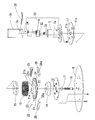
- the seat portion 1 is rotatably attached to the upper end of the pedestal 2 having the gas cylinder 4 built therein, and the lower end is attached to the base 8 via the tilting means 10.
- the gas cylinder 4 is actuated, and the seat moves up and down.
- the gas cylinder 4 is covered with two upper and lower upper covers 3a and 3b.
- the total height of the stool is 840 mm
- the vertical movement stroke is 260 mm.
- the tilting means 10 has a coiled wave spring 13 sandwiched from above and below by a spring retainer 11 and a spring receiver 12 and fastened at its center with a mounting bolt 16. Inside the coiled wave spring 13, the upper surface attached to the spring receiver 12 with a bolt 14 c is a conical locking member 14, and the lower surface attached to the spring retainer 11 with a bolt 15 a so as to face the upper part. A flat contact member 15 is provided.
- the locking member 14 and the abutting member 15 are disk-shaped, and the outer peripheral portion is a spring guide for the coiled wave spring 13. It is fastened to a fixed nut 11b.
- the mounting bolt 16 has a lower end side as a head, a spherical member 17 is provided at the neck, and a concave spherical portion 14 a into which the spherical member 17 is fitted is formed on the locking member 14.
- 18 is a nut for preventing rotation.
- the tilting means 10 is configured in this way, when the seated person leans over his / her weight in either direction, the coiled wave spring 13 is bent, the pedestal 2 is tilted, and the spring retainer 11 is tilted. At this time, the spherical member 17 of the mounting bolt 16 is fitted into the concave spherical surface portion 14a of the locking member 14, and the mounting bolt 16 is inclined.
- the seat portion 1 is inclined at a predetermined angle (here, 8 degrees)
- the conical upper surface of the locking member 14 comes into contact with the lower surface of the flat contact member 15 and does not tilt further.
- the degree of tilting needs to be limited to a predetermined angle because of the possibility of falling, but in this embodiment, the maximum tilting angle is set to 8 degrees, and at this time, the locking member 14 contacts the contact member 15. I try to touch. Since this tilt angle varies depending on the seated person, it is not shown in FIGS. 1 and 2, but the tilt angle that can be adjusted by the seated person can be switched between 6 degrees and 4.5 degrees and 3 degrees. Next, an embodiment provided with the corner switching means 20 will be described.
- the tilt angle switching means 20 includes a locking ring 21 provided concentrically outside the coiled wave spring 13, a ring guide 25 disposed on the outer periphery thereof, and a tilt limit.
- a switch 26 for switching the corner and a stopper 11c fixed on the back surface of the spring retainer 11 are provided.
- the locking ring 21 is provided with a guide groove 22 on the outer periphery, and is rotatably provided by engaging with a locking member 25 a provided on the ring guide 25.
- the locking ring 21 is provided with a lever 23 for manually rotating the locking ring 21.
- locking protrusions 21 a and 21 b having different heights that come into contact with the stopper 11 c when the tilt limit angle is 3 degrees or 6 degrees, and 8 degrees or more (here 10), locking projections 21c that come into contact with the stopper 11c are provided at four locations on the circumference for every quarter circle.
- the locking projection 21c is selected here, the locking member 14 contacts the contact member 15 and does not tilt any further when the inclination angle becomes 8 degrees.
- the ring guide 25 has an arc shape, and is provided at two locations on the outer periphery of the locking ring 21, and includes a locking member 25 a that engages with the guide groove 22.
- the switch 26 is configured to rotate the locking ring 21 so that the locking convex portion having a desired tilt limit angle is positioned directly below the stopper 11c, and has the same shape as the ring guide 25.
- a stopper 26a made of a spring and a ball is provided.
- the stopper 26a is engaged with a positioning guide 24 formed by a groove and a locking hole provided in the locking ring 21. When the stopper 26a reaches a predetermined position, the ball of the stopper 26a is fitted into the locking hole of the positioning guide 24 and is engaged. The position of the stop ring 21 is held.
- the tilt angle switching means 20 is configured in this way, the seated person once tilts the body in either direction to tilt the seat 1, and the tilt limit when the stopper 11c of the spring retainer 11 is locked is reached. If the angle is not appropriate, it can be switched by operating the lever 23. When the lever 23 is operated to rotate the locking ring 21, the positions of the locking projections 21a to 21c facing the stopper 11c change, and the stopper 26a engages with the positioning guide 24, and a predetermined position (stopper) 11c), it will be locked. If the tilt angle is not appropriate, the tilt limit angle can be switched by further rotating the locking ring 21.
- FIG. 6 is an explanatory diagram of this, and the tilt angle switching means 20 is omitted for the sake of clarity.
- This spring stiffness adjusting means 30 changes the distance between the spring retainer 11 holding the coiled wave spring 13 and the spring receiver 12, and is attached to a fixed nut 11 b fixed at the center of the upper surface of the spring retainer 11. This is done by loosely tightening the mounting bolt 16 screwed in.
- the spring stiffness adjusting means 30 has a worm wheel 31 attached to the upper end of the mounting bolt 16, and a worm gear 34 fixed to the worm shaft 33 meshes with the worm wheel 31.
- the worm shaft 33 is provided with a hexagonal hole into which the spanner 35 is fitted.
- the worm wheel 31, the worm shaft 33, and the worm gear 34 are mounted on a gear case 32 (see FIG. 5), and the outer side is covered with a bracket 7 fixed to the spring retainer 11 and a lower cover 3b that is externally fitted thereto. Therefore, openings 7a and 3c are provided in the bracket 7 and the lower cover 3b so that the hexagon wrench 35 can be inserted.
- the spring stiffness adjusting means 30 is configured as described above, the mounting bolt 16 is rotated by rotating the worm shaft 33 with the spanner 35, and the spring retainer 11 can be moved up and down.
- the spring retainer 11 is lowered, the stiffness with respect to the tilt of the coiled wave spring 13 increases, and the tilt becomes difficult.
- the spring retainer 11 is raised, the stiffness against the tilting is weakened and the tilting is easy.
- FIG. 7 is the same as that of the above embodiment, but the components are the same. That is, the upper end of the gas cylinder 43 is fixed to the seat portion 40, and the lower end is connected to the above-described tilting means 10 attached to the base 8.
- a lever 44 for extending and contracting is provided at the upper end of the gas cylinder 43, and the side surface is covered with an upper cover 41 and a lower cover 42 having a one-step small diameter.
- the stool has a total height of 400 mm and a stroke of 55 mm.
- the tilt angle switching means 20 and the stiffness adjusting means 30 with respect to the tilt of the coiled wave spring 13 described in the above embodiment are provided in the same manner as described above.
- the upper cover 41 tilts with the tilting of the seat portion 40, but the lower cover 42 does not tilt. Still, since the diameter of the lower cover 42 is large, the opening 42a for inserting the lever 23 and the hexagon stick spanner 35 extends to the vicinity of the lower cover 42.
- FIG. 8 is a front sectional view of the tilting means 10 ⁇ / b> A.
- the coiled wave spring 13 is sandwiched between the spring retainer 11 and the spring receiver 12, and the center thereof is fastened with the mounting bolt 16.
- a contact member 15 having a flat upper surface attached to the spring receiver 12 with a bolt 15a, and a lower surface attached to the spring retainer 11 with a bolt 14c facing the upper portion thereof.
- a locking member 14 formed in a conical shape is provided inside the coiled wave spring 13, a contact member 15 having a flat upper surface attached to the spring receiver 12 with a bolt 15a, and a lower surface attached to the spring retainer 11 with a bolt 14c facing the upper portion thereof.
- a locking member 14 formed in a conical shape is provided.
- the locking member 14 and the abutting member 15 are disk-shaped, and the outer peripheral portion is a spring guide for the coiled wave spring 13.
- a hole is formed in the central portion, and the mounting bolt 16 is inserted with the head facing up. It is fastened to the fixed nut 8b.
- a spherical member 17 is provided on the neck portion of the mounting bolt 16, and a concave spherical portion 14 a is formed on the locking member 14.
- 16a is a collar for making the distance between the spring retainer 11 and the spring support 12 constant, and is removed when the adjusting means 30 for stiffness against the tilt of the coiled wave spring 13 is provided.
- the tilting means 10A is different from the tilting means 10 in that the mounting bolt 16 has the head up. Although omitted here, the tilt angle switching means 20 and the spring stiffness adjusting means 30 can be provided in the same manner as described above.
- the tilting means 10A tilts the pedestal 2 and tilts the spring presser 11 fixed thereto.
- the locking member 14 is tilted with the spring retainer 11, the concave spherical surface portion 14a is moved by being fitted to the spherical member 17 of the mounting bolt 16, and the mounting bolt 16 is not tilted.
- the spring retainer 11 is inclined at a predetermined angle (here, 8 degrees), the lower surface of the locking member 14 comes into contact with the contact member 15 and does not tilt further.
- FIG. 9 is a front cross-sectional view showing another embodiment of the tilting means 10.
- This tilting means 10B is obtained by adding an elastic member 13a to the tilting means 10A. That is, a cylindrical synthetic rubber elastic member 13a is provided between the contact member 15 on the spring receiver 12 and the upper locking member 14, and the contact member 15 has a ring shape for holding the elastic member 13a. A spring groove 15b is formed, and a similar spring groove 14d is provided in the opposing locking member 14. Since the tilting means 10B is configured in this way, it is possible to improve the feeling of supporting spring force and tilting by using an appropriate elastic member 13a.
- FIG. 10 is a front sectional view showing an entire tiltable stool having a constant seat height
- FIG. 11 is a front sectional view showing an embodiment of a stool having a low seat
- 12 is an enlarged view of the tilting means 10C
- FIG. 13 is a cross-sectional view showing the state of the tilting means 10C when the seat portions 50 and 55 are tilted.
- a seat 50 is fixed on the upper surface of the pedestal 51, and the same tilting means 10 ⁇ / b> C as that of the above embodiment is provided at the lower part of the pedestal 51, and Attached.
- the height of the seat cannot be raised or lowered, but it can be rotated by the rotating member 19.
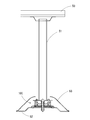
- the stool shown in FIG. 11 has a seat 55 fixed to the upper end of a support 56 in the shape of a pan, and tilting means 10C is provided at the lower part of the support 56.
- the stool is attached to the table 57 via the rotating member 19. It has been.
- the seat is low and does not move up and down.
- the inside of the support body 56 is a cavity, and the seat portion 55 is detachably attached to the support body 56.
- the tilting means 10 ⁇ / b> C has a coiled wave spring 13 sandwiched between a spring retainer 11 and a spring receiver 12, and a center thereof is fastened with a mounting bolt 16.
- an abutting member 15 having a flat upper surface attached to the spring receiver 12 with a bolt 12b and a lower surface attached to the spring retainer 11 with a bolt 14c facing the upper part thereof are provided.
- a locking member 14 formed in a conical shape is provided.
- the locking member 14 and the abutting member 15 are disk-shaped and have a hole in the center, and a mounting bolt 16 is inserted with the head facing up and fastened to a fixed nut 8 b on the back surface of the base 8.
- a spherical member 17 is provided at the neck of the mounting bolt 16, and a concave spherical portion 14 a that fits the locking member 14 is formed.
- a thrust bearing 19 is provided on the back surface of the spring receiver 12.
- 15c is a flooring plate
- 16a is a collar
- 18 is a nut.
- the tilting means 10C is configured as described above, when the seated person tilts the seat portion 50 with his / her body weight in any direction, the coiled wave spring 13 bends and the pedestal 51 and the spring retainer 11 tilt. . At this time, the locking member 14 is also tilted, the concave spherical surface portion 14a is fitted to the spherical member 17 of the mounting bolt 16, the locking member 14 moves, and the mounting bolt 16 remains vertical and does not tilt.
- the seat portion 50 is inclined at a predetermined angle (here, 8 degrees)
- the conical upper surface of the locking member 14 comes into contact with the lower surface of the flat contact member 15 and does not tilt further.
- FIG. 13 shows the state of the tilting means 10 ⁇ / b> C when the seat 50 is tilted. Further, when a rotating force is applied to the seat portion 50, this force is transmitted from the spring retainer 11 to the upper end of the coiled wave spring 13, but is rotated by the thrust bearing 19 so that the coiled wave spring 13 is twisted. There is no twist.
- the tilting means 10C in FIG. 11 is the same as that in FIG.
- a seat 60 is fixed on the upper surface of the support body 61 as in FIG. 11, and the tilting means 10 ⁇ / b> C similar to the above embodiment is provided at the lower portion of the support body 61. It is attached via a rotating member 19.
- the support body 61 is formed in a curved surface having a slight bulge from the seat 60, and the inside thereof is a hollow space for storing articles, and a plurality of openings 61a are provided. Since the tilting means 10C is the same as described above, description thereof is omitted.
- FIG. 15 The lounge chair shown in FIG. 15 is used in a relaxed manner with one seat with an inclined backrest.
- a seat 71 integrated with the backrest 71 a is fixed to a support 72, and the support 72 is attached to a base 73. It is attached to a fixed table 74 via tilting means 10C.
- the support body 72 is formed in a concave shape from below the seat portion 71 to both sides of the seat portion 71 as viewed from the front of the lounge chair 70, and an armrest 72a is provided at the upper end.
- the tilting means 10C is the same as that shown in FIG.
- FIG. 16 shows another embodiment of the lounge chair.
- a support base 83 is fixed to the lower portion of the seat 81 integrated with the backrest 81a, and the tilting means 10C is provided. It is attached to the base 8 via The tilting means 10C is shown in FIG. 11, and a thrust bearing 19 is also provided.
- 82 is an armrest.
- the lounge chair 90 of FIG. 16B has a support base 93 fixed to the lower part of a seat 91 integrated with the backrest, and is attached to the base 8 via tilting means 10C.
- the tilting means 10C is shown in FIG. 11, and a thrust bearing 19 is also provided.
- the lounge chairs 70, 80, 90 are configured as described above, when the seated person sits on the seats 71, 81, 91 and shifts their weight in any direction, the lounge chairs 70, 80, 90 are tilted accordingly.
- a predetermined angle (8 degrees) When tilted to a predetermined angle (8 degrees), the conical upper surface of the locking member 14 comes into contact with the lower surface of the flat contact member 15 and does not tilt further.
- the thrust bearing 19 can be rotated in any direction.
- the tilt angle switching means 20 and the spring stiffness adjusting means 30 are not provided, but can be provided in the same manner as described above.
Landscapes
- Chairs Characterized By Structure (AREA)
- Special Chairs (AREA)
Abstract
Description
この種のスツールには、座の直下に傾動手段を設けたものと、床面近くに傾動手段を設けたもの(例えば、特許文献1)がある。
しかしながら、特許文献1の傾動機構は、第1と第2のリンクでユニバーサルとし、コイルスプリングを6個配置しているので、傾動する方向によって傾動の感じが異なり、構造が複雑で、部品数も多く、高価なものとなっている。また、傾動する限度角は、変えることができないので、人によっては傾きすぎて危険を感じる場合がある。
バネ受けは、床面に載置されるベース上に固設され、バネ押えは脚柱の下端に固設している。
コイルドウェーブスプリングは、JSMA(日本バネ工業会の規格)SB009に規定されているもので、帯状のばね鋼をコイル状に巻き回すとともに、ばね鋼の長さ方向に連続する波型を形成した圧縮型コイルばねである。
座の傾動に伴ってコイルドウェーブスプリングが撓んでバネ押えが傾くように取付けボルトには球面部材を設けるとともにバネ押えまたはバネ受けには該球面部材に嵌合する凹球面部を設ける。
この凹球面部は、バネ押え近くまたはバネ受け近くのいずれかに設ける。バネ押え近くに設けた場合はバネ押えが傾動しても取付ボルトは傾動しないが、バネ受け近くに設けた場合は取付ボルトが傾動する。
座の高さが低い場合は、寸胴鍋状の支持体の上端に座を固設し、該支持体の下端を該バネ押えに固設し、該バネ受けは回動部材を介してベースに固設する。
なお、回動部材はコイルドウェーブスプリングの中心を中心としてバネ受けが回動可能に設けられるもので、特に限定しないが、スラストベアリングを使用するのが望ましい。
これは、スツールでは、着座者が傾動させるだけでなく回転も同時に行われるのが一般的なので、コイルドウェーブスプリングへ回転力を負荷させない意味もある。
なお、支持体は寸胴鍋状、すなわち、座の外周の径の円筒形のものに限定するものではなく、下方に漸次大きくしたものや中央部を絞ったものなども含まれる。また、デザイン上の観点から凹凸を形成してもよい。
また、座の傾動限度角は、体格や年齢、性別などで異なり、着座者によって変えたい場合がある。この場合は、上記傾動手段の係止部材が当接したときの角度を最大として、これより小さくした複数の傾動限度角を、着座者が適宜選定できるようにして設けるとよい。
ここで、「複数個の係止凸部を四方に」という意味は、円を十字状に四分割し、各エリアに高さの異なる係止凸部をワンセットずつ設けることをいう。これにより、座をいずれの方向へ傾けても傾斜限度角になると、バネ押えのストッパが同じ高さの係止凸部に当接する。
傾動限度角を切換える場合は、所望の限度角の係止凸部がバネ押えのストッパの真下に位置するように係止リングを回動させる必要がある。
これを簡便に行うには、請求項7に記載のように、係止リングの外周に係合溝と複数個の係止穴を設けるとともに、該外周の外側にバネで該係止穴へ嵌合する係止部材を設け、座の傾動限度角を変えるため前記係止リングを回動させたとき、該係止部材が係止穴へ嵌合し、係止リングが位置決めされる位置決め手段を設けるのが望ましい。
図1は、請求項1の発明のスツールの全体を示す正面断面図であり、図2は図1のA部拡大図である。図3は傾斜角度切換手段を設けた実施の形態を示す断面図、図4は図3のB-B視図である。また、図5は傾動手段、傾斜角切換手段およびコイルドウェーブスプリングの傾動に対するこわさの調整手段の分解斜視図である。図6は、コイルドウェーブスプリングの傾動に対するこわさの調整を行うための手段の説明図である。
この傾動角度は、着座者によっても個人差があるので、図1および図2では記載されていないが、着座者が調整できる傾動角として6度と4.5度と、3度に切換えられる傾動角切換手段20を備えた実施例を次に説明する。
また、係止リング21の上面には、傾動制限角度がここでは、3度、6度のときに、ストッパ11cと当接する高さの異なる係止凸部21a、21bと、8度以上(ここでは10度としている)でストッパ11cに当接する係止凸部21cが4分の1円毎に円周4箇所に設けられている。なお、ここで係止凸部21cを選択したときは、傾斜角度が8度になると係止部材14が当接部材15に当接してそれ以上傾斜しない。
切換器26は、係止リング21を回動させて所望の傾動限度角の係止凸部がストッパ11cの真下に位置するように位置決めするもので、リングガイド25と同様の形状をしており、バネとボールからなるストッパ26aを備えている。
ストッパ26aは、係止リング21に設けた溝と係止穴からなる位置決めガイド24と係合し、所定の位置にくるとストッパ26aのボールが位置決めガイド24の係止穴に嵌合して係止リング21の位置を保持する。
レバー23を操作して係止リング21を回動させると、ストッパ11cと対向する係止凸部21a~21cの位置が変わり、ストッパ26aが位置決めガイド24に係合して、所定の位置(ストッパ11cの真下)にくるとロックされる。その傾動角度が適当でない場合は、さらに係止リング21を回動させて傾動限度角を切換えることができる。
このバネこわさ調整手段30は、コイルドウェーブスプリング13を挟持しているバネ押え11とバネ受け12間の距離を変えるものであり、バネ押え11の上面中央に固設された固設ナット11bにねじ込まれている取付ボルト16を緩締することにより行っている。
ウォームホィール31,ウォーム軸33、ウォームギア34は、ギアケース32に装着され(図5参照)、外側は、バネ押え11に固設されたブラケット7およびそれに外嵌された下カバー3bに覆われているので、六角棒スパナ35が挿入できるように、ブラケット7および下カバー3bには開口7a、3cが設けられている。
図7に示すスツールは、上記の実施の形態と外観が異なるだけで、構成部品は同様である。すなわち、座部40にはガスシリンダ43の上端が固設され、下端はベース8に取り付けられた上記説明した傾動手段10に連結されている。
ガスシリンダ43の上端部には伸縮させるためのレバー44が設けられ、側面を上カバー41と一段小径の下カバー42で覆われている。なお、このスツールの大きさは、ここでは、全高は400mm、ストロークは55mmとしている。
なお、上カバー41は、座部40の傾動に伴って傾動するが、下カバー42は傾動しない。それでも、下カバー42の径が大きいので、レバー23や六角棒スパナ35を挿入する開口42aは、下カバー42の近くまで延出させている。
図8は傾動手段10Aの正面断面図を示すもので、バネ押え11とバネ受け12でコイルドウェーブスプリング13を挟んでその中央を取付ボルト16で締結している。そして、コイルドウェーブスプリング13の内側には、バネ受け12にボルト15aで取り付けられた上面が平坦な当接部材15と、その上部に対向してバネ押え11にボルト14cで取り付けられた下面が円錐状に形成された係止部材14が設けられている。
傾動手段10Aは、着座者が座をいずれかの方向へ傾けると、それにともなって脚柱2が傾動し、これに固設されているバネ押え11が傾く。このとき、係止部材14がバネ押え11に伴って傾動し凹球面部14aが取付ボルト16の球面部材17と嵌合して動き、取付けボルト16は傾動しない。そして、バネ押え11が所定の角度(ここでは8度)傾くと、係止部材14の下面が当接部材15に当接し、それ以上は傾動しない。
この傾動手段10Bは、傾動手段10Aに弾性部材13aを追加したものである。
すなわち、バネ受け12上の当接部材15と上方の係止部材14の間に円筒状の合成ゴム製の弾性部材13aが設けられ、当接部材15にはこれを保持するためのリング状のバネ用溝15bが形成され、対抗する係止部材14にも同様のバネ用溝14dが設けられている。
傾動手段10Bはこのように構成されているので、適宜な弾性部材13aを使用することにより支持バネ力や傾動に対するフィーリングを向上させることができる。
図10は、座の高さが一定で高い傾動可能なスツールの全体を示す正面断面図であり、図11は座の低いスツールの実施の形態を示す正面断面図である。また、図12は、傾動手段10Cの拡大図で、図13は座部50、55を傾動させたときの傾動手段10Cの状態を示す断面図である。
図11に示すスツールは寸胴鍋状の支持体56の上端に座部55が固設され、該支持体56の下部には傾動手段10Cが設けられ、置台57に回動部材19を介して取り付けられている。座の高さは低く昇降しない。また、支持体56の内部は、空洞であり、座部55は支持体56に脱着可能に取り付けられている。
取付けボルト16の首部には球面部材17が設けられ、係止部材14に嵌合する凹球面部14aが形成されている。そして、バネ受け12の裏面にはスラストベアリング19が設けられている。なお、図12において、15cは敷板、16aはカラー、18はナットである。
そして、座部50が所定の角度(ここでは、8度としている)傾くと、係止部材14の円錐状の上面が平坦な当接部材15の下面に当接し、それ以上は傾動しない。
図13は、座部50を傾動させたときの傾動手段10Cの状態を示している。
また、座部50に回転する力がかかった場合は、この力はバネ押え11からコイルドウェーブスプリング13の上端に伝達されるが、スラストベアリング19によって回動し、コイルドウェーブスプリング13が捩じられることはない。
なお、図11における傾動手段10Cは、図10の場合と同じであるので説明は省略する。
支持体61は座60からやや膨らみを持った曲面に形成され、内部は、空洞で物品の収納ができ、開口部61aが複数個設けられている。
傾動手段10Cは上記と同じであるので、説明は省略する。
図15のラウンジチェアは、背もたれに傾斜のある1人掛けのゆったりして使用されるもので、背もたれ71aと一体の座部71が支持体72に固設され、該支持体72はベース73に固設された置台74に傾動手段10Cを介して取り付けられている。
支持体72は、ラウンジチェア70の正面から見て座部71の下方から座部71の両側へ凹字状に形成され、上端には肘掛け72aが設けられている。
傾動手段10Cは、上記図11に示したものと同じであるので、説明は省略する。
また、図16(b)のラウンジチェア90は、背もたれと一体の座部91の下部に支持台93が固設され、傾動手段10Cを介してベース8に取り付けられている。傾動手段10Cは上記11図に示すもので、スラストベアリング19も付設されている。
この実施の形態では、傾動角切換手段20およびバネこわさ調整手段30は設けていないが、上記と同様に設けることができる。
2 脚柱
3a 上カバー
3b 下カバー
3c 開口
4 ガスシリンダ
5 カバー
6 レバー
7 ブラケット
7a 開口
8 ベース
8a ボルト
8b 固設ナット
10 傾動手段
10A 傾動手段
10B 傾動手段
10C 傾動手段
11 バネ押え
11a ナット
11b 固設ナット
11c ストッパ
11d ボルト
12 バネ受け
12a ナット
12b ボルト
13 コイルドウェーブスプリング
13a 弾性部材
14 係止部材
14a 凹球面部
14b 円錐面
14c ボルト
14d バネ用溝
15 当接部材
15a ボルト
15b バネ用溝
15c 敷板
16 取付ボルト
16a カラー
17 球面部材
18 ナット
19 スラストベアリング
20 傾動角切換手段
21 係止リング
21a、21b,21c 係止凸部
22 ガイド溝
23 レバー
24 切換ガイド
25 リングガイド
25a 凸部
26 切換器
26a ストッパ
30 バネのこわさ調整手段
31 ウォームホィール
32 ギアケース
33 ウォーム軸
34 ウォームギア
35 スパナ
40 座部
41 上カバー
42 下カバー
42a 開口
43 ガスシリンダ
44 レバー
50 座部
51 脚柱
52 置台
55 座部
56 支持体
57 置台
60 座部
61 支持体
61a 開口部
62 ベース
70 ラウンジチェア
71 座部
71a 背もたれ
72 支持体
72a 肘掛け
73 ベース
74 置台
80 ラウンジチェア
81 座部
81a 背もたれ
82 肘掛け
83 支持台
90 ラウンジチェア
91 座部
93 支持台
Claims (8)
- 床面近くに傾動手段を設けて、座を任意の方向へ傾動可能とした椅子において、該傾動手段は、コイルドウェーブスプリングをバネ押えとバネ受けで挟み、バネ押えが傾動可能に中心を取付ボルトで締結され、座が所定角度傾斜すると当接する凸円錐形の係止部材が該コイルドウェーブスプリングの内側で該バネ押えまたはバネ受けに固設されたものであり、座は、ガスシリンダを内装した脚柱の上端に固設し、該脚柱の下端は該バネ押えに固設されたことを特徴とする傾動可能なスツール。
- 床面近くに傾動手段を設けて、座を任意の方向へ傾動可能とした椅子において、該傾動
手段は、コイルドウェーブスプリングをバネ押えとバネ受けで挟み、バネ押えが傾動可能
に中心が取付ボルトで締結され、座が所定角度傾斜すると当接する凸円錐形の係止部材が
該コイルドウェーブスプリングの内側で該バネ押えまたはバネ受けに固設されたものであ
り、座は、固定長さの脚柱の上端または寸胴鍋状の支持体の上端に固設され、該脚柱または支持体の下端は該バネ押えに固設され、該バネ受けの裏面には回動部材が設けられたことを特徴とする傾動可能なスツール。 - 前記寸胴鍋状の支持体の上端に設ける座を脱着可能として、該支持体の中を物品の収納スペースとし、または、座を支持体の上端に固設して支持体の側面に複数の開口部を設けたことを特徴とする請求項2に記載の傾動可能なスツール。
- 床面近くに傾動手段を設けて、座を任意の方向へ傾動可能とした椅子であって、該傾動手段は、コイルドウェーブスプリングをバネ押えとバネ受けで挟み、バネ押えが傾動可能に中心が取付ボルトで締結され、座が所定角度傾斜すると当接する凸円錐形の係止部材が該コイルドウェーブスプリングの内側で該バネ押えまたはバネ受けに固設されたものであり、上端に肘掛けが設けられ、座の下方から座の両側へ凹字状に形成された支持体を設け、または、背もたれと一体の座の下部に支持台を固設し、該支持体または支持台の下端は該バネ押えに固設され、該バネ受けはベース上に回動部材を介して取り付けられたことを特徴とする傾動可能なラウンジチェア。
- 前記バネ押えとバネ受けの間に座が傾斜すると付勢する弾性部材を設けたことを特徴とする請求項1ないし請求項4のいずれかに記載の傾動可能なスツールまたはラウンジチェア。
- 前記コイルドウェーブスプリングの外側へ同心円状に、高さの異なる複数個の係止凸部を四方に形成した係止リングを回動可能に設け、前記バネ押えの裏面に該係止凸部に当接するストッパを四方に固設し、該係止リングには回転させるためのレバーを付設し、座の傾動限度を変更できるようにしたことを特徴とする請求項1ないし請求項5のいずれかに記載の傾動可能なスツールまたはラウンジチェア。
- 座の傾動限度を変えるため前記係止リングを回動させるとき、係止凸部が簡便に所定の
位置に移動されるように、前記係止リングの外周に係合溝と複数個の係止穴を設けるとと
もに、該外周の外側にバネで該係止穴へ嵌合する係止部材を設け、前記係止リングを回動
させたとき、該係止部材が係止穴へ嵌合して位置決めされる位置決め手段を設けたことを
特徴とする請求項6に記載の傾動可能なスツールまたはラウンジチェア。 - 前記コイルドウェーブスプリングの傾動に対する強さを変更するため、前記バネ抑えの
上面中央または前記バネ受けの裏面中央に固設されたナットにねじ込まれた取付ボルトの先端に回動レバーを付設し、バネ押えとバネ受けとの距離を変更できるようにしたことを特徴とする請求項1~請求項7のいずれかに記載の傾動可能なスツールまたはラウンジチェア。
Priority Applications (5)
| Application Number | Priority Date | Filing Date | Title |
|---|---|---|---|
| KR1020187000139A KR101930837B1 (ko) | 2016-08-18 | 2017-08-01 | 경동 가능한 체어 |
| JP2018534323A JP6709475B2 (ja) | 2016-08-18 | 2017-08-01 | 傾動可能なスツールまたはラウンジチェア |
| EP17841366.2A EP3476255B1 (en) | 2016-08-18 | 2017-08-01 | Tiltable stool or lounge chair |
| CN201780004064.0A CN108289547B (zh) | 2016-08-18 | 2017-08-01 | 可倾斜的凳子或可倾斜的休闲椅 |
| US16/225,442 US10433644B2 (en) | 2016-08-18 | 2018-12-19 | Tiltable stool and tiltable lounge chair |
Applications Claiming Priority (2)
| Application Number | Priority Date | Filing Date | Title |
|---|---|---|---|
| JP2016-160618 | 2016-08-18 | ||
| JP2016160618 | 2016-08-18 |
Related Child Applications (1)
| Application Number | Title | Priority Date | Filing Date |
|---|---|---|---|
| US16/225,442 Continuation US10433644B2 (en) | 2016-08-18 | 2018-12-19 | Tiltable stool and tiltable lounge chair |
Publications (1)
| Publication Number | Publication Date |
|---|---|
| WO2018034139A1 true WO2018034139A1 (ja) | 2018-02-22 |
Family
ID=61197235
Family Applications (1)
| Application Number | Title | Priority Date | Filing Date |
|---|---|---|---|
| PCT/JP2017/027823 Ceased WO2018034139A1 (ja) | 2016-08-18 | 2017-08-01 | 傾動可能なスツールまたはラウンジチェア |
Country Status (6)
| Country | Link |
|---|---|
| US (1) | US10433644B2 (ja) |
| EP (1) | EP3476255B1 (ja) |
| JP (1) | JP6709475B2 (ja) |
| KR (1) | KR101930837B1 (ja) |
| CN (1) | CN108289547B (ja) |
| WO (1) | WO2018034139A1 (ja) |
Cited By (1)
| Publication number | Priority date | Publication date | Assignee | Title |
|---|---|---|---|---|
| JP2020065872A (ja) * | 2018-10-26 | 2020-04-30 | 有限会社ルネセイコウ | 椅子 |
Families Citing this family (13)
| Publication number | Priority date | Publication date | Assignee | Title |
|---|---|---|---|---|
| WO2017204648A1 (en) * | 2016-05-24 | 2017-11-30 | Engell Maria Terese | Balance chair |
| USD853163S1 (en) * | 2017-05-15 | 2019-07-09 | Bock 1 Gmbh & Co. Kg | Office chair |
| CN108371436B (zh) * | 2018-04-25 | 2023-10-27 | 严澄宇 | 弹力跷跷板式的自由倾仰机构及自由调节转椅 |
| KR102203145B1 (ko) * | 2018-09-13 | 2021-01-14 | 주식회사 미도화학 | 자가 수직복원이 가능한 스툴 |
| KR102058116B1 (ko) * | 2019-02-11 | 2019-12-23 | 주식회사 아이체 | 경동 의자 |
| EP3701839B1 (en) * | 2019-02-27 | 2022-11-16 | L&P Property Management Company | Control mechanism for a chair |
| IT201900003255A1 (it) * | 2019-03-06 | 2020-09-06 | Donati Spa | Base di appoggio per una seduta oscillante |
| CN110101234A (zh) * | 2019-05-08 | 2019-08-09 | 宋为民 | 一种椅子 |
| DE112020002777T5 (de) * | 2019-06-10 | 2022-03-03 | Inventor Group Gmbh | Kippbarer Hocker |
| KR102082352B1 (ko) * | 2019-06-25 | 2020-02-27 | 주식회사 아이체 | 의자의 전방위 탄성지지 기구 |
| KR102437284B1 (ko) | 2020-12-22 | 2022-08-29 | 주식회사 포머스 | 임의 방향으로 좌판의 틸팅이 가능한 의자 |
| KR102439019B1 (ko) * | 2022-04-15 | 2022-08-31 | 손원희 | 노약자용 승강식 의자 |
| NO348077B1 (en) * | 2023-12-08 | 2024-07-15 | Ekornes AS | A rotation assembly and a furniture comprising a rotation assembly |
Citations (7)
| Publication number | Priority date | Publication date | Assignee | Title |
|---|---|---|---|---|
| JPS5273805U (ja) * | 1975-10-02 | 1977-06-02 | ||
| JPS5491304U (ja) * | 1977-12-08 | 1979-06-28 | ||
| JPS56137657U (ja) * | 1980-03-19 | 1981-10-19 | ||
| JP2007007249A (ja) * | 2005-07-01 | 2007-01-18 | Houtoku:Kk | 椅子 |
| JP3165162U (ja) * | 2010-07-28 | 2011-01-06 | 長貞 林 | 安楽ロッキングチェア |
| JP2015192825A (ja) * | 2014-03-31 | 2015-11-05 | 飛騨産業株式会社 | 椅子 |
| JP2015202343A (ja) * | 2014-04-16 | 2015-11-16 | 株式会社岡村製作所 | 椅子 |
Family Cites Families (26)
| Publication number | Priority date | Publication date | Assignee | Title |
|---|---|---|---|---|
| DE287619C (ja) * | ||||
| DE4244657C2 (de) * | 1992-03-27 | 1998-11-26 | Josef Gloeckl | Aktivdynamische Sitzvorrichtung |
| AUPN779996A0 (en) * | 1996-01-30 | 1996-02-22 | Hibberd, Ronald Charles | Tilting chair |
| US6209843B1 (en) * | 1999-06-14 | 2001-04-03 | R. Brantley Smith, Jr. | Pivotal rocking chair base |
| US6834916B2 (en) * | 2001-05-11 | 2004-12-28 | White Pine Concepts, Llc | Gardening stool |
| DE202004005366U1 (de) * | 2004-04-05 | 2004-06-24 | VS Vereinigte Spezialmöbelfabriken GmbH & Co. | Stuhl mit Wippmechanik |
| US6997511B2 (en) * | 2004-04-09 | 2006-02-14 | Transfert Plus, S.E.C. | Seating device |
| US7547067B2 (en) * | 2004-12-01 | 2009-06-16 | Keilhauer (Partnership) | Tilt and swivel chair and mechanism therefor |
| US7100983B1 (en) * | 2004-12-09 | 2006-09-05 | Gant Richard A | Lumbar flexing seating apparatus |
| DE102005005089A1 (de) * | 2005-02-03 | 2006-08-10 | Josef GLÖCKL | Tragelement für ein Sitzmöbel |
| ES2527757T3 (es) * | 2005-03-01 | 2015-01-29 | Haworth, Inc. | Mecanismo de regulación de tensión |
| KR100678653B1 (ko) * | 2005-05-16 | 2007-02-05 | 기 석 우 | 다기능 의자 |
| US7533506B2 (en) * | 2006-01-11 | 2009-05-19 | Platt Robert E | Bracket for mounting and vertically leveling a post on a surface |
| JP2007268118A (ja) * | 2006-03-31 | 2007-10-18 | Takara Belmont Co Ltd | 座部が揺動可能なスツール |
| KR200432389Y1 (ko) * | 2006-08-30 | 2006-12-05 | 심승용 | 의자용 좌판의 완충구조 |
| KR20080006155U (ko) * | 2007-06-08 | 2008-12-11 | 임이재 | 의자방향 복원장치 |
| KR200437095Y1 (ko) * | 2007-08-16 | 2007-11-01 | 고진옥 | 수납 공간을 가지는 의자 |
| NO328660B1 (no) * | 2008-04-02 | 2010-04-19 | Sapdesign As | Anordning ved stol |
| DE202009017844U1 (de) * | 2009-12-23 | 2010-07-22 | Topstar Gmbh | Kippvorrichtung für einen Stuhl |
| DE102010020503A1 (de) * | 2010-05-14 | 2011-11-17 | Josef Glöckl | Sitzvorrichtung mit beweglichem Sitz |
| CN201798301U (zh) * | 2010-06-15 | 2011-04-20 | 王柏荣 | 万向摇摆椅 |
| DE102011101388B3 (de) * | 2011-05-12 | 2012-11-15 | Stephan Meyer | Sitzmöbel |
| KR101500616B1 (ko) * | 2013-06-03 | 2015-03-18 | 정대훈 | 허리운동기능을 갖는 의자 |
| CN203789496U (zh) * | 2014-03-28 | 2014-08-27 | 安徽久工健业股份有限公司 | 摇摆椅 |
| JP6462442B2 (ja) * | 2015-03-19 | 2019-01-30 | 株式会社エルゴジャパン | 椅子用座の支持構造体及びそれを備える椅子 |
| CN105852487B (zh) * | 2016-05-31 | 2019-01-22 | 厦门康乐佳运动器材有限公司 | 健身座椅 |
-
2017
- 2017-08-01 CN CN201780004064.0A patent/CN108289547B/zh active Active
- 2017-08-01 EP EP17841366.2A patent/EP3476255B1/en active Active
- 2017-08-01 JP JP2018534323A patent/JP6709475B2/ja active Active
- 2017-08-01 KR KR1020187000139A patent/KR101930837B1/ko active Active
- 2017-08-01 WO PCT/JP2017/027823 patent/WO2018034139A1/ja not_active Ceased
-
2018
- 2018-12-19 US US16/225,442 patent/US10433644B2/en active Active
Patent Citations (7)
| Publication number | Priority date | Publication date | Assignee | Title |
|---|---|---|---|---|
| JPS5273805U (ja) * | 1975-10-02 | 1977-06-02 | ||
| JPS5491304U (ja) * | 1977-12-08 | 1979-06-28 | ||
| JPS56137657U (ja) * | 1980-03-19 | 1981-10-19 | ||
| JP2007007249A (ja) * | 2005-07-01 | 2007-01-18 | Houtoku:Kk | 椅子 |
| JP3165162U (ja) * | 2010-07-28 | 2011-01-06 | 長貞 林 | 安楽ロッキングチェア |
| JP2015192825A (ja) * | 2014-03-31 | 2015-11-05 | 飛騨産業株式会社 | 椅子 |
| JP2015202343A (ja) * | 2014-04-16 | 2015-11-16 | 株式会社岡村製作所 | 椅子 |
Cited By (2)
| Publication number | Priority date | Publication date | Assignee | Title |
|---|---|---|---|---|
| JP2020065872A (ja) * | 2018-10-26 | 2020-04-30 | 有限会社ルネセイコウ | 椅子 |
| JP7078263B2 (ja) | 2018-10-26 | 2022-05-31 | 有限会社ルネセイコウ | 椅子 |
Also Published As
| Publication number | Publication date |
|---|---|
| CN108289547A (zh) | 2018-07-17 |
| EP3476255B1 (en) | 2021-01-06 |
| EP3476255A4 (en) | 2020-01-01 |
| EP3476255A1 (en) | 2019-05-01 |
| KR101930837B1 (ko) | 2018-12-19 |
| US20190116979A1 (en) | 2019-04-25 |
| KR20180031670A (ko) | 2018-03-28 |
| US10433644B2 (en) | 2019-10-08 |
| JP6709475B2 (ja) | 2020-06-17 |
| CN108289547B (zh) | 2021-09-24 |
| JPWO2018034139A1 (ja) | 2019-06-13 |
Similar Documents
| Publication | Publication Date | Title |
|---|---|---|
| WO2018034139A1 (ja) | 傾動可能なスツールまたはラウンジチェア | |
| US4277102A (en) | Chair | |
| US5884976A (en) | Chair swivel arm rest | |
| US4709894A (en) | Slip connector for weight actuated height adjustors | |
| JP2008535595A (ja) | 特にオフィス椅子用の肘掛け | |
| WO2000024295A1 (en) | Universal tilt mechanism for a chair | |
| KR101370845B1 (ko) | 틸팅 제한부가 부설된 의자 어셈블리 | |
| CA2550837A1 (en) | Dynamic seating device | |
| US11160377B2 (en) | Synchronous chair mechanism and chair having same | |
| KR101358007B1 (ko) | 의자의 좌판 각도 조절장치 | |
| JP2003225136A (ja) | 椅 子 | |
| KR101056745B1 (ko) | 의자용 좌판 틸팅장치 | |
| JP6339841B2 (ja) | 椅子 | |
| JP4518649B2 (ja) | 椅子の肘掛け装置 | |
| KR102437284B1 (ko) | 임의 방향으로 좌판의 틸팅이 가능한 의자 | |
| JP2002051870A (ja) | 椅子の肘掛け装置 | |
| KR102917288B1 (ko) | 럼버서포터를 포함하는 의자 | |
| JP4578645B2 (ja) | 椅子の肘掛け装置 | |
| JP7638513B2 (ja) | 座部跳ね上げ装置 | |
| JP3120862U (ja) | 椅子傾動装置 | |
| EP3632266B1 (en) | Supporting structure for a seat | |
| JP4564265B2 (ja) | 椅子 | |
| KR100598428B1 (ko) | 무게중심이동회전장치를 이용한 안락의자. | |
| JP7382187B2 (ja) | 椅子 | |
| KR200411914Y1 (ko) | 의자용 헤드 레스트의 회동 구조 |
Legal Events
| Date | Code | Title | Description |
|---|---|---|---|
| ENP | Entry into the national phase |
Ref document number: 20187000139 Country of ref document: KR Kind code of ref document: A |
|
| WWE | Wipo information: entry into national phase |
Ref document number: 2018534323 Country of ref document: JP |
|
| 121 | Ep: the epo has been informed by wipo that ep was designated in this application |
Ref document number: 17841366 Country of ref document: EP Kind code of ref document: A1 |
|
| NENP | Non-entry into the national phase |
Ref country code: DE |
|
| ENP | Entry into the national phase |
Ref document number: 2017841366 Country of ref document: EP Effective date: 20190318 |