WO2018034170A1 - X線検査装置 - Google Patents
X線検査装置 Download PDFInfo
- Publication number
- WO2018034170A1 WO2018034170A1 PCT/JP2017/028304 JP2017028304W WO2018034170A1 WO 2018034170 A1 WO2018034170 A1 WO 2018034170A1 JP 2017028304 W JP2017028304 W JP 2017028304W WO 2018034170 A1 WO2018034170 A1 WO 2018034170A1
- Authority
- WO
- WIPO (PCT)
- Prior art keywords
- ray
- unit
- output
- irradiation
- control
- Prior art date
- Legal status (The legal status is an assumption and is not a legal conclusion. Google has not performed a legal analysis and makes no representation as to the accuracy of the status listed.)
- Ceased
Links
Images

Classifications
-
- G—PHYSICS
- G01—MEASURING; TESTING
- G01N—INVESTIGATING OR ANALYSING MATERIALS BY DETERMINING THEIR CHEMICAL OR PHYSICAL PROPERTIES
- G01N23/00—Investigating or analysing materials by the use of wave or particle radiation, e.g. X-rays or neutrons, not covered by groups G01N3/00 – G01N17/00, G01N21/00 or G01N22/00
- G01N23/02—Investigating or analysing materials by the use of wave or particle radiation, e.g. X-rays or neutrons, not covered by groups G01N3/00 – G01N17/00, G01N21/00 or G01N22/00 by transmitting the radiation through the material
- G01N23/04—Investigating or analysing materials by the use of wave or particle radiation, e.g. X-rays or neutrons, not covered by groups G01N3/00 – G01N17/00, G01N21/00 or G01N22/00 by transmitting the radiation through the material and forming images of the material
- G01N23/043—Investigating or analysing materials by the use of wave or particle radiation, e.g. X-rays or neutrons, not covered by groups G01N3/00 – G01N17/00, G01N21/00 or G01N22/00 by transmitting the radiation through the material and forming images of the material using fluoroscopic examination, with visual observation or video transmission of fluoroscopic images
-
- G—PHYSICS
- G01—MEASURING; TESTING
- G01N—INVESTIGATING OR ANALYSING MATERIALS BY DETERMINING THEIR CHEMICAL OR PHYSICAL PROPERTIES
- G01N23/00—Investigating or analysing materials by the use of wave or particle radiation, e.g. X-rays or neutrons, not covered by groups G01N3/00 – G01N17/00, G01N21/00 or G01N22/00
- G01N23/02—Investigating or analysing materials by the use of wave or particle radiation, e.g. X-rays or neutrons, not covered by groups G01N3/00 – G01N17/00, G01N21/00 or G01N22/00 by transmitting the radiation through the material
- G01N23/06—Investigating or analysing materials by the use of wave or particle radiation, e.g. X-rays or neutrons, not covered by groups G01N3/00 – G01N17/00, G01N21/00 or G01N22/00 by transmitting the radiation through the material and measuring the absorption
- G01N23/18—Investigating the presence of flaws defects or foreign matter
-
- G—PHYSICS
- G01—MEASURING; TESTING
- G01N—INVESTIGATING OR ANALYSING MATERIALS BY DETERMINING THEIR CHEMICAL OR PHYSICAL PROPERTIES
- G01N23/00—Investigating or analysing materials by the use of wave or particle radiation, e.g. X-rays or neutrons, not covered by groups G01N3/00 – G01N17/00, G01N21/00 or G01N22/00
- G01N23/02—Investigating or analysing materials by the use of wave or particle radiation, e.g. X-rays or neutrons, not covered by groups G01N3/00 – G01N17/00, G01N21/00 or G01N22/00 by transmitting the radiation through the material
- G01N23/04—Investigating or analysing materials by the use of wave or particle radiation, e.g. X-rays or neutrons, not covered by groups G01N3/00 – G01N17/00, G01N21/00 or G01N22/00 by transmitting the radiation through the material and forming images of the material
-
- G—PHYSICS
- G01—MEASURING; TESTING
- G01V—GEOPHYSICS; GRAVITATIONAL MEASUREMENTS; DETECTING MASSES OR OBJECTS; TAGS
- G01V5/00—Prospecting or detecting by the use of ionising radiation, e.g. of natural or induced radioactivity
- G01V5/20—Detecting prohibited goods, e.g. weapons, explosives, hazardous substances, contraband or smuggled objects
-
- G—PHYSICS
- G06—COMPUTING OR CALCULATING; COUNTING
- G06T—IMAGE DATA PROCESSING OR GENERATION, IN GENERAL
- G06T7/00—Image analysis
- G06T7/0002—Inspection of images, e.g. flaw detection
- G06T7/0004—Industrial image inspection
-
- H—ELECTRICITY
- H05—ELECTRIC TECHNIQUES NOT OTHERWISE PROVIDED FOR
- H05G—X-RAY TECHNIQUE
- H05G1/00—X-ray apparatus involving X-ray tubes; Circuits therefor
- H05G1/08—Electrical details
- H05G1/10—Power supply arrangements for feeding the X-ray tube
-
- H—ELECTRICITY
- H05—ELECTRIC TECHNIQUES NOT OTHERWISE PROVIDED FOR
- H05G—X-RAY TECHNIQUE
- H05G1/00—X-ray apparatus involving X-ray tubes; Circuits therefor
- H05G1/08—Electrical details
- H05G1/26—Measuring, controlling or protecting
- H05G1/30—Controlling
-
- H—ELECTRICITY
- H05—ELECTRIC TECHNIQUES NOT OTHERWISE PROVIDED FOR
- H05G—X-RAY TECHNIQUE
- H05G1/00—X-ray apparatus involving X-ray tubes; Circuits therefor
- H05G1/08—Electrical details
- H05G1/26—Measuring, controlling or protecting
- H05G1/30—Controlling
- H05G1/36—Temperature of anode; Brightness of image power
-
- G—PHYSICS
- G01—MEASURING; TESTING
- G01N—INVESTIGATING OR ANALYSING MATERIALS BY DETERMINING THEIR CHEMICAL OR PHYSICAL PROPERTIES
- G01N2223/00—Investigating materials by wave or particle radiation
- G01N2223/10—Different kinds of radiation or particles
- G01N2223/101—Different kinds of radiation or particles electromagnetic radiation
- G01N2223/1016—X-ray
-
- G—PHYSICS
- G01—MEASURING; TESTING
- G01N—INVESTIGATING OR ANALYSING MATERIALS BY DETERMINING THEIR CHEMICAL OR PHYSICAL PROPERTIES
- G01N2223/00—Investigating materials by wave or particle radiation
- G01N2223/30—Accessories, mechanical or electrical features
- G01N2223/303—Accessories, mechanical or electrical features calibrating, standardising
-
- G—PHYSICS
- G06—COMPUTING OR CALCULATING; COUNTING
- G06T—IMAGE DATA PROCESSING OR GENERATION, IN GENERAL
- G06T2207/00—Indexing scheme for image analysis or image enhancement
- G06T2207/10—Image acquisition modality
- G06T2207/10116—X-ray image
Definitions
- This disclosure relates to an X-ray inspection apparatus.
- an X-ray inspection apparatus As an X-ray inspection apparatus, an X-ray irradiation unit that irradiates an article with X-rays, an X-ray detection unit that detects X-rays transmitted through the article, and an X-ray of the article based on a signal output from the X-ray detection unit
- an X-ray inspection apparatus including an inspection unit that generates a transmission image and inspects an article based on the X-ray transmission image, and a control unit that controls the X-ray irradiation unit and the X-ray detection unit ( For example, see Patent Document 1).
- the control unit corrects the sensitivity of the X-ray detection unit in accordance with changes with time of the X-ray irradiation unit and the X-ray detection unit.
- the sensitivity of the X-ray detection unit is adjusted after the X-ray irradiation unit is controlled so that the irradiation output of the X-ray irradiation unit becomes the maximum value.
- the higher the output of the X-ray irradiation unit the faster the deterioration of the X-ray irradiation unit and the X-ray detection unit proceeds. Therefore, it is required to suppress the deterioration of the X-ray irradiation unit and the X-ray detection unit while ensuring the inspection performance of the article.
- This disclosure is intended to provide an X-ray inspection apparatus capable of suppressing deterioration of an X-ray irradiation unit and an X-ray detection unit while ensuring the inspection performance of an article.
- An X-ray inspection apparatus includes an X-ray irradiation unit that irradiates an article with X-rays, an X-ray detection unit that detects X-rays transmitted through the article, and a signal output from the X-ray detection unit.
- the X-ray irradiation unit is controlled so that the irradiation output of the X-ray irradiation unit becomes the first irradiation output
- the detection output of the X-ray detection unit decreases, the X-ray is set so that the irradiation output increases. 1st control which controls an irradiation part is performed.
- the control unit controls the X-ray irradiation unit so that the irradiation output of the X-ray irradiation unit becomes the first irradiation output
- the detection output of the X-ray detection unit decreases
- the X-ray irradiation unit or the X-ray detection unit may be deteriorated.
- the sensitivity of the X-ray detection unit is set relatively high in advance and the first irradiation output of the X-ray irradiation unit is set smaller than the maximum value, the irradiation output of the X-ray irradiation unit is maximum.
- the control unit executes the first control to secure a room for increasing the irradiation output of the X-ray irradiation unit. Performance degradation can be avoided. Therefore, deterioration of the X-ray irradiation unit and the X-ray detection unit can be suppressed while ensuring the inspection performance of the article.
- the control unit detects X-rays that are not irradiated to the article and are not irradiated to the article by the X-ray irradiated by the X-ray irradiation unit.
- the first control may be executed in a state where the unit is detecting. In this case, the probability that the detection output of the X-ray detection unit is reduced due to the deterioration of the X-ray irradiation unit or the X-ray detection unit is higher than the state in which the X-ray detection unit detects X-rays that have passed through the article. Become. Therefore, the control unit can appropriately execute the first control.
- the control unit decreases the detection output when the X-ray irradiation unit is controlled so that the irradiation output becomes the second irradiation output larger than the first irradiation output.
- the second control for controlling the X-ray detection unit so as to increase the detection output is executed, and the first control and the second control may be switchable.
- the operator of the X-ray inspection apparatus selects either one of the first control that suppresses the irradiation output of the X-ray irradiation unit and the second control that increases the irradiation output of the X-ray irradiation unit. be able to.
- control unit executes the first control that controls the X-ray irradiation unit with an input current that is smaller than the maximum input current to the X-ray irradiation unit, the power consumption of the X-ray irradiation unit can be reduced. it can.
- a display unit that displays the time during which the control unit executes the first control and information related to the irradiation output of the X-ray irradiation unit controlled by the first control. May further be included.
- the operator of the X-ray inspection apparatus can confirm that the deterioration of the X-ray irradiation unit and the X-ray detection unit is suppressed by the display unit.
- FIG. 1 is a configuration diagram of an X-ray inspection apparatus according to an embodiment of the present disclosure.
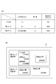
- FIG. 2 is a flowchart illustrating the calibration process of the X-ray inspection apparatus of FIG. (A) of FIG. 3 is a table
- FIG. 3B is a schematic view showing a display unit of the X-ray inspection apparatus of FIG.
- the X-ray inspection apparatus 1 includes an apparatus main body 2, support legs 3, a shield box 4, a transfer conveyor 5, an X-ray irradiation unit 6, an X-ray detection unit 7, and a display.
- An operation unit (display unit) 8 and a control unit 10 are provided.
- the X-ray inspection apparatus 1 acquires an X-ray transmission image of the article G while conveying the article G, and inspects the article G based on the X-ray transmission image (for example, storage number inspection, foreign matter mixing inspection, missing item inspection). , Crack inspection etc.).
- the X-ray inspection apparatus 1 is connected to an external power source (not shown). The external power supply supplies the X-ray inspection apparatus 1 with power for inspecting the article G.
- the apparatus main body 2 houses the control unit 10 and the like.
- the support leg 3 supports the apparatus main body 2.
- the shield box 4 is provided in the apparatus body 2 and prevents X-ray leakage.
- a carry-in port 4a and a carry-out port 4b are formed in the shield box 4.
- the article G before inspection is carried into the shield box 4 from the carry-in conveyor 51 through the carry-in entrance 4a, and the article G after examination is carried out from the shield box 4 to the carry-out conveyor 52 through the carry-out opening 4b.
- Each of the carry-in entrance 4a and the carry-out exit 4b is provided with an X-ray shielding curtain (not shown) that prevents X-ray leakage.
- the transport conveyor 5 is disposed in the shield box 4 and transports the article G along the transport direction A from the carry-in port 4a to the carry-out port 4b.
- the conveyor 5 is a belt conveyor that is stretched between the carry-in port 4a and the carry-out port 4b, for example.
- the X-ray irradiation unit 6 is arranged in the shield box 4 and irradiates the article G conveyed by the conveyor 5 with X-rays.
- the X-ray irradiation unit 6 includes, for example, an X-ray tube (not shown) that emits X-rays, and a collimator that spreads the X-rays emitted from the X-ray tube in a fan shape in a plane perpendicular to the transport direction A. is doing.
- the X-ray detection unit 7 is disposed in the shield box 4 and detects X-rays transmitted through the article G and the conveyor 5.
- the X-ray detection unit 7 is configured as a line sensor, for example.
- the X-ray detection unit 7 includes a plurality of photodiodes arranged one-dimensionally along a horizontal direction perpendicular to the transport direction A, and a scintillator disposed on the X-ray incident side with respect to each photodiode. And have.
- X-rays incident on the scintillator are converted into light, and light incident on each photodiode is converted into an electric signal.
- the detection output of the X-ray detection unit 7 increases as the sensitivity of the X-ray detection unit 7 increases, and decreases as the sensitivity of the X-ray detection unit 7 decreases.
- the detection output of the X-ray detection unit 7 is expressed by, for example, the number of X-ray photons (cps: count per second, etc.).
- the X-ray detection unit 7 deteriorates according to the time when the X-ray is incident and the intensity of the incident X-ray. In general, the deterioration of the X-ray detection unit 7 progresses faster as the intensity of the incident X-ray increases, and progresses slower as the intensity of the incident X-ray decreases. That is, in general, the deterioration of the X-ray detection unit 7 progresses faster as the input current to the X-ray irradiation unit 6 increases, and progresses slower as the input current to the X-ray irradiation unit 6 decreases.
- the display operation unit 8 is provided in the apparatus main body 2 and displays various information and accepts input of various conditions.
- the display operation unit 8 is a liquid crystal display, for example, and displays an operation screen as a touch panel. In this case, the operator can input various conditions including selection of switching between the first mode and the second mode, which will be described later, via the display operation unit 8. Further, as will be described later, the display operation unit 8 displays the time during which the control unit 10 executes the first control and information related to the irradiation output of the X-ray irradiation unit 6 controlled by the first control. To do.
- the calibration process includes a first mode and a second mode.
- the first mode is a calibration process that suppresses the deterioration of the X-ray irradiation unit 6 and the X-ray detection unit 7 and reduces the power consumption of the X-ray irradiation unit 6 by suppressing the irradiation output of the X-ray irradiation unit 6.
- the second mode is a mode (so-called normal mode) in which calibration processing is performed to increase the irradiation output of the X-ray irradiation unit 6 so as to sharpen the X-ray transmission image of the article G.
- the first mode and the second mode can be switched based on, for example, a selection operation by the operator via the display operation unit 8.
- the control unit 10 sets the input current to the X-ray irradiation unit 6 to the first input current in a state where the sensitivity of the X-ray detection unit 7 is fixed to the first sensitivity.
- the control unit 10 controls the X-ray irradiation unit 6 so that the irradiation output of the X-ray irradiation unit 6 becomes the first irradiation output
- the detection output of the X-ray detection unit 7 decreases.
- 1st control which controls the X-ray irradiation part 6 so that the irradiation output of the X-ray irradiation part 6 increases is performed.
- the first irradiation output is the intensity of X-rays output from the X-ray tube when the input current input to the X-ray tube of the X-ray irradiation unit 6 is the first input current.
- the control unit 10 sets the sensitivity of the X-ray detection unit 7 to the second sensitivity in a state where the irradiation output of the X-ray irradiation unit 6 is fixed to the second irradiation output larger than the first irradiation output. To do.
- the control unit 10 controls the X-ray irradiation unit 6 so that the irradiation output of the X-ray irradiation unit 6 becomes the second irradiation output
- the detection output of the X-ray detection unit 7 decreases.
- 2nd control which controls the X-ray detection part 7 is performed so that the detection output of the X-ray detection part 7 may increase.
- the second irradiation output is the intensity of X-rays output from the X-ray tube in a state where the input current input to the X-ray tube of the X-ray irradiation unit 6 is a second input current larger than the first input current.
- the second input current is a predetermined rated current (that is, the maximum value of the input current) of the X-ray tube.
- the control unit 10 supplies the X-ray irradiation unit 6 such that the detection output of the X-ray detection unit 7 is a test detection output smaller than the upper limit value (for example, 3000 counts) of the inspection range.
- the relationship of the detection output of the X-ray detection unit 7 with respect to the irradiation output of the X-ray irradiation unit 6 is acquired with the input current and the sensitivity of the X-ray detection unit 7.
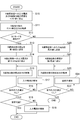
- the control unit 10 sets the input current to the X-ray irradiation unit 6 in a state where the sensitivity of the X-ray detection unit 7 is set to a test value (for example, 1 time). Is set to a test value (for example, 1.0 mA), and the X-ray irradiation unit 6 is controlled so that the irradiation output of the X-ray irradiation unit 6 becomes the test irradiation output (step S10).
- the control unit 10 acquires the test detection output of the X-ray detection unit 7 (step S11).
- the input current (test value) to the X-ray irradiation unit 6 is 1.0 mA
- the relationship that the test detection output of the X-ray detection unit 7 is 150 counts is acquired.
- the control unit 10 determines whether or not the first mode is selected in the X-ray inspection apparatus 1 (step S12). In step S12, when the control unit 10 determines that the first mode is selected in the X-ray inspection apparatus 1, the control unit 10 sets the sensitivity of the X-ray detection unit 7 to the first sensitivity (step S13). . In response to setting the sensitivity of the X-ray detection unit 7 to the first sensitivity in step S13, the control unit 10 sets the input current to the X-ray irradiation unit 6 to the first input current, and the X-ray irradiation unit. The X-ray irradiation unit 6 is controlled so that the irradiation output of 6 becomes the first irradiation output (step S14).
- the first sensitivity is higher than the second sensitivity, as will be described later.
- the second sensitivity is set to double when the input current to the X-ray irradiation unit 6 is set to the maximum value (10.0 mA) in the second mode
- the first sensitivity is four times.
- the control unit 10 controls the X-ray irradiation unit 6 so that the irradiation output of the X-ray irradiation unit 6 becomes the first irradiation output.
- the detection output of the unit 7 decreases, the X-ray irradiation unit 6 or the X-ray detection unit 7 may be deteriorated.
- the input current to the X-ray irradiation unit 6 is a first input current that is smaller than the maximum value. Therefore, there is room for increasing the input current to the X-ray irradiation unit 6. Therefore, the control unit 10 acquires the detection output of the X-ray detection unit 7 (step S15), and determines whether or not the detection output of the X-ray detection unit 7 is decreased (step S16).
- step S16 when the control unit 10 determines that there is a decrease in the detection output of the X-ray detection unit 7, the control unit 10 determines that the X-rays have decreased due to the deterioration of the X-ray irradiation unit 6 or the X-ray detection unit 7.
- the first control for controlling the X-ray irradiation unit 6 so as to increase the irradiation output of the X-ray irradiation unit 6 is executed (step S17).
- control unit 10 sets the sensitivity of the X-ray detection unit 7 to the first sensitivity higher than the second sensitivity, and the input current to the X-ray irradiation unit 6 becomes the first input current smaller than the maximum value. If the detection output of the X-ray detector 7 decreases when the X-ray irradiation unit 6 is controlled, the irradiation output of the X-ray irradiation unit 6 is increased by increasing the input current to the X-ray irradiation unit 6. Increase.
- step S17 the process proceeds to step S15, and the control unit 10 re-acquires the detection output of the X-ray detection unit 7 with the irradiation output of the X-ray irradiation unit 6 increased.
- step S16 when the control unit 10 determines that there is no decrease in the detection output of the X-ray detection unit 7, the inspection of the article G is performed with the set input current to the X-ray irradiation unit 6 and the sensitivity of the X-ray detection unit 7. See if it is possible.
- the control unit 10 determines whether or not the inspection of the article G is possible based on whether or not the variation (average, deviation, etc.) of the detection output of the X-ray detection unit 7 is within a predetermined range ( Step S18).
- step S18 when the control unit 10 determines that the inspection of the article G is possible, the control unit 10 ends the calibration process in the first mode. Thereafter, the X-ray inspection apparatus 1 inspects the article G with the set input current to the X-ray irradiation unit 6 and the sensitivity of the X-ray detection unit 7.
- control unit 10 determines in step S18 that the inspection of the article G is not possible, the control unit 10 causes the variation (average, deviation, etc.) of the detection output of the X-ray detection unit 7 to be within a predetermined range.
- the input current to the X-ray irradiation unit 6 is increased, and the input current to the X-ray irradiation unit 6 is reset (step S19). Thereby, the performance of the inspection of the article G can be ensured.
- step S19 the sensitivity of the X-ray detection unit 7 is increased together with the input current to the X-ray irradiation unit 6 so that the variation in the detection output of the X-ray detection unit 7 is within a predetermined range, and the X-ray irradiation is performed.
- the input current to the unit 6 and the sensitivity of the X-ray detection unit 7 may be reset.
- the control unit 10 ends the calibration process in the first mode.
- the article G is inspected with the set input current to the X-ray irradiation unit 6 and the sensitivity of the X-ray detection unit 7.
- control unit 10 determines in step S12 that the second mode is selected in the X-ray inspection apparatus 1
- the control unit 10 sets the input current to the X-ray irradiation unit 6 to the maximum value (10.0 mA).
- the X-ray irradiation unit 6 is controlled so that the irradiation output of the X-ray irradiation unit 6 becomes the second irradiation output (step S20).
- the control unit 10 sets the sensitivity of the X-ray detection unit 7 to the second sensitivity (Step S21).
- the X-ray detection unit is controlled in spite of the control unit 10 controlling the X-ray irradiation unit 6 so that the irradiation output of the X-ray irradiation unit 6 becomes the second irradiation output under the certain conditions described above. 7 may decrease in the X-ray irradiation unit 6 or the X-ray detection unit 7. Therefore, the control unit 10 acquires the detection output of the X-ray detection unit 7 (step S22), and determines whether or not the detection output of the X-ray detection unit 7 is decreased (step S23).
- step S23 when the control unit 10 determines that there is a decrease in the detection output of the X-ray detection unit 7, the control unit 10 determines that the X-ray decreased due to the progress of deterioration of the X-ray irradiation unit 6 or the X-ray detection unit 7.
- the second control for controlling the X-ray detection unit 7 so as to increase the detection output of the X-ray detection unit 7 is executed (step S24).
- step S24 the process proceeds to step S22, and the control unit 10 re-acquires the detection output of the X-ray detection unit 7 with the detection output of the X-ray detection unit 7 increased.
- step S23 when the control unit 10 determines that the detection output of the X-ray detection unit 7 does not decrease, the control unit 10 ends the calibration process in the second mode. Thereafter, the X-ray inspection apparatus 1 inspects the article G with the set input current to the X-ray irradiation unit 6 and the sensitivity of the X-ray detection unit 7.
- the control unit 10 controls the time during which the first control is executed (hereinafter also referred to as the first mode operation time) and the first control.
- Information related to the irradiation output of the X-ray irradiation unit 6 is displayed on the display operation unit 8.
- the “time during which the first control is executed” displayed on the display operation unit 8 is the first control process for increasing the input current to the X-ray irradiation unit 6 (the process of step S17 in FIG. 2).
- the time during which the calibration process (the processes in steps S10 to S19 in FIG.
- the control unit 10 determines the actual value of the input current (first input current) to the X-ray irradiation unit 6 and the X-ray irradiation unit during the first mode operation time. 6, the actual value of the power consumption (first irradiation output), the actual value of the first mode operation time, and the actual value of the power consumption in the X-ray irradiation unit 6 are displayed on the display operation unit 8.
- the actual value of the input current to the X-ray irradiation unit 6 is 5.0 mA
- the actual power consumption value in the X-ray irradiation unit 6 is 250 W
- the first mode operation time (operation time) ) Is 100 hours
- the actual value of power consumption in the X-ray irradiation unit 6 is 25 kWh.
- the input current and sensitivity in the first mode shown in FIG. 3A are set as the input current and sensitivity in the first mode.
- the control unit 10 causes the display operation unit 8 to display the estimated value of the power consumption in the X-ray irradiation unit 6 when it is assumed that the second mode is selected in the first mode operation time.
- the estimated value of the power consumption in the X-ray irradiation unit 6 is 50 kWh.
- the input current and sensitivity in the second mode shown in FIG. 3A are set as the input current and sensitivity in the second mode.
- the control unit 10 operates the X-ray inspection apparatus 1 in the first mode by using the difference between the estimated value of the power consumption in the second mode and the actual value of the power consumption in the first mode. As a result, the display operation unit 8 displays the reduced power amount that is estimated to be reduced. In the example of FIG. 3B, the reduced power amount is 25 kWh.
- the control unit 10 executes the first control to increase the irradiation output of the X-ray irradiation unit 6.
- the room to be used is ensured, and the deterioration of the inspection performance of the article G can be avoided. Therefore, deterioration of the X-ray irradiation unit 6 and the X-ray detection unit 7 can be suppressed while ensuring the inspection performance of the article G. As a result, the life time of the X-ray irradiation unit 6 and the X-ray detection unit 7 can be delayed (long life).
- the control unit detects that the X-ray irradiated by the X-ray irradiation unit 6 is not irradiated on the article G and the X-ray not irradiated on the article G is X-ray detection unit 7.
- the first control is executed in a state in which is detected. Under this condition, the X-ray detection unit 7 detects the X-ray detection unit 7 due to deterioration of the X-ray irradiation unit 6 or the X-ray detection unit 7 as compared with a state in which the X-ray detection unit 7 detects X-rays transmitted through the article G. The probability that the output will decrease increases. Accordingly, the control unit 10 can appropriately execute the first control.
- the control unit 10 controls the X-ray irradiation unit 6 so that the irradiation output of the X-ray irradiation unit 6 becomes a second irradiation output larger than the first irradiation output.
- the second control for controlling the X-ray detection unit 7 so as to increase the detection output of the X-ray detection unit 7 is executed.
- the first control (first mode) and the second control (second mode) can be switched.
- the operator of the X-ray inspection apparatus 1 controls either one of the first control that suppresses the irradiation output of the X-ray irradiation unit 6 and the second control that increases the irradiation output of the X-ray irradiation unit 6. Can be selected.
- the control unit 10 sets the sensitivity of the X-ray detection unit 7 to the second sensitivity and sets the input current to the X-ray irradiation unit 6 to a maximum value.
- the detection output of the X-ray detection unit 7 is increased by increasing the sensitivity of the X-ray detection unit 7.
- the control unit 10 sets the sensitivity of the X-ray detection unit 7 to a first sensitivity higher than the second sensitivity, and the input current to the X-ray irradiation unit 6 is smaller than the maximum value.
- the X-ray inspection apparatus 1 includes information on the time during which the control unit 10 executes the first control and the irradiation output of the X-ray irradiation unit 6 controlled by the first control (input current to the X-ray irradiation unit 6). , The power consumption amount of the X-ray irradiation unit 6 and the power amount reduced by the first control).
- This display operation unit 8 allows the operator of the X-ray inspection apparatus 1 to confirm that deterioration of the X-ray irradiation unit 6 and the X-ray detection unit 7 is suppressed.
- the control part 10 is a case where the detection output of the X-ray detection part 7 reduces on the fixed conditions with few factors which fluctuate the irradiation output of the X-ray irradiation part 6, and the detection output of the X-ray detection part 7.
- the first control or the second control is executed on the assumption that deterioration has progressed to the X-ray irradiation unit 6 or the X-ray detection unit 7.
- the control unit 10 may perform the first operation under a condition in which there is a factor that causes the detection output of the X-ray detection unit 7 to fluctuate with a constant fluctuation pattern even if the irradiation output of the X-ray irradiation unit 6 is substantially constant.
- the control unit 10 stores, for example, the reference fluctuation pattern of the detection output of the X-ray detection unit 7 and cancels the fluctuation of the detection output caused by the factor to thereby cancel the X-ray detection unit. 7 may be extracted, and it may be determined that the deterioration of the irradiation output of the X-ray irradiation unit 6 or the detection output of the X-ray detection unit 7 has progressed, and the first control and the second control may be executed. .
- control unit 10 controls the X-ray irradiation unit 6 so that the input current to the X-ray irradiation unit 6 becomes the maximum value in the second control, but the X-ray irradiation unit 6 in the second control. As long as the input current to is larger than the input current to the X-ray irradiation unit 6 in the first control, it may not be the maximum value.
- control unit 10 executes the calibration process after the X-ray inspection apparatus 1 is started and before the inspection of the article G by the X-ray inspection apparatus 1 is started.
- the calibration process may be executed between G inspections.
- control unit 10 functions as an inspection unit, and the control unit 10 and the inspection unit are physically integrated.
- control unit 10 and the inspection unit are physically It may be configured separately.
- the display operation unit 8 of the X-ray inspection apparatus 1 functions as a display unit.
- a display provided separately from the X-ray inspection apparatus 1 may function as a display unit. .
- the present disclosure generates an optical transmission image by detecting light (near infrared rays, other electromagnetic waves) transmitted through an article, and inspects the article based on the optical transmission image, except for an X-ray inspection apparatus. Applicable to the device. However, when X-rays are used as light, even if the article G is packaged, the lack of the article G is inspected without being affected by the packaging material or the printing applied to the packaging material. can do.
Landscapes
- Health & Medical Sciences (AREA)
- Physics & Mathematics (AREA)
- General Physics & Mathematics (AREA)
- General Health & Medical Sciences (AREA)
- Life Sciences & Earth Sciences (AREA)
- Engineering & Computer Science (AREA)
- Immunology (AREA)
- Pathology (AREA)
- Chemical & Material Sciences (AREA)
- Analytical Chemistry (AREA)
- Biochemistry (AREA)
- Toxicology (AREA)
- Theoretical Computer Science (AREA)
- Computer Vision & Pattern Recognition (AREA)
- Quality & Reliability (AREA)
- Multimedia (AREA)
- Nuclear Medicine, Radiotherapy & Molecular Imaging (AREA)
- Radiology & Medical Imaging (AREA)
- High Energy & Nuclear Physics (AREA)
- General Life Sciences & Earth Sciences (AREA)
- Geophysics (AREA)
- Analysing Materials By The Use Of Radiation (AREA)
- Measurement Of Radiation (AREA)
Abstract
X線検査装置は、物品にX線を照射するX線照射部と、物品を透過したX線を検出するX線検出部と、X線検出部から出力された信号に基づいて物品のX線透過画像を生成し、X線透過画像に基づいて物品の検査を行う検査部と、X線照射部及びX線検出部を制御する制御部と、を備える。制御部は、X線照射部の照射出力が第1照射出力となるようにX線照射部を制御している場合に、X線検出部の検出出力が減少したときには、照射出力が増大するようにX線照射部を制御する第1制御を実行する。
Description
本開示は、X線検査装置に関する。
X線検査装置として、物品にX線を照射するX線照射部と、物品を透過したX線を検出するX線検出部と、X線検出部から出力された信号に基づいて物品のX線透過画像を生成し、X線透過画像に基づいて物品の検査を行う検査部と、X線照射部及びX線検出部を制御する制御部と、を備えるX線検査装置が知られている(例えば、特許文献1参照)。特許文献1記載のX線検査装置では、制御部は、X線照射部及びX線検出部の経時変化に応じて、X線検出部の感度を補正する。
X線検査装置では、物品の検査の性能を重視する観点で、X線照射部の照射出力が最大値となるようにX線照射部を制御した上でX線検出部の感度を調整することが一般的である。しかしながら、X線照射部の出カが高いほど、X線照射部及びX線検出部の劣化が速く進行する。そのため、物品の検査の性能を確保しつつX線照射部及びX線検出部の劣化を抑制することが求められている。
本開示は、物品の検査の性能を確保しつつX線照射部及びX線検出部の劣化を抑制することができるX線検査装置を提供することを目的とする。
本開示の一形態のX線検査装置は、物品にX線を照射するX線照射部と、物品を透過したX線を検出するX線検出部と、X線検出部から出力された信号に基づいて物品のX線透過画像を生成し、X線透過画像に基づいて物品の検査を行う検査部と、X線照射部及びX線検出部を制御する制御部と、を備え、制御部は、X線照射部の照射出力が第1照射出力となるようにX線照射部を制御している場合に、X線検出部の検出出力が減少したときには、照射出力が増大するようにX線照射部を制御する第1制御を実行する。
このX線検査装置では、X線照射部の照射出力が第1照射出力となるようにX線照射部を制御部が制御している場合に、X線検出部の検出出力が減少したときには、X線照射部又はX線検出部の劣化が進行している可能性がある。このとき、例えば、予めX線検出部の感度を比較的高く設定しX線照射部の第1照射出力を最大値よりも小さく設定しておけば、X線照射部の照射出力が最大の場合と比べてX線照射部及びX線検出部の劣化が抑制されると共に、制御部が第1制御を実行することでX線照射部の照射出力を増大させる余地が確保され、物品の検査の性能の低下を回避することができる。したがって、物品の検査の性能を確保しつつX線照射部及びX線検出部の劣化を抑制することができる。
本開示の一形態のX線検査装置では、制御部は、X線照射部により照射されたX線が物品には照射されておらず、且つ、物品に照射されていないX線をX線検出部が検出している状態で、第1制御を実行してもよい。この場合、X線検出部が物品を透過したX線を検出する状態と比べて、X線照射部又はX線検出部の劣化に起因してX線検出部の検出出力が減少する蓋然性が高くなる。よって、適切に制御部が第1制御を実行することが可能となる。
本開示の一形態のX線検査装置では、制御部は、照射出力が第1照射出力よりも大きい第2照射出力となるようにX線照射部を制御している場合に、検出出力が減少したときには、検出出力が増大するようにX線検出部を制御する第2制御を実行し、第1制御と第2制御とは、切り替え可能であってもよい。この場合、X線検査装置のオペレータは、X線照射部の照射出力を抑えた第1制御と、X線照射部の照射出力を高めた第2制御と、の何れか一方の制御を選択することができる。
本開示の一形態のX線検査装置では、制御部は、第2制御において、X線検出部の感度を第2感度に設定すると共にX線照射部への入力電流が最大値となるようにX線照射部を制御している場合に、検出出力が減少したときには、感度を増加させることで検出出力を増大させ、第1制御において、感度を第2感度よりも高い第1感度に設定すると共に入力電流が最大値よりも小さい第1入力電流となるようにX線照射部を制御している場合に、検出出力が減少したときには、入力電流を増加させることで照射出力を増大させてもよい。この場合、X線照射部への入力電流が最大値よりも小さい入力電流でX線照射部を制御する第1制御を制御部が実行するため、X線照射部の電力消費を低減することができる。
本開示の一形態のX線検査装置では、制御部が第1制御を実行している時間と、当該第1制御により制御されたX線照射部の照射出力に関する情報と、を表示する表示部を更に有してもよい。この場合、表示部により、X線照射部及びX線検出部の劣化が抑制されていることをX線検査装置のオペレータが確認することができる。
本開示によれば、物品の検査の性能を確保しつつX線照射部及びX線検出部の劣化を抑制することが可能となる。
以下、本開示の実施形態について、図面を参照して詳細に説明する。なお、各図において同一又は相当部分には同一符号を付し、重複する説明を省略する。
図1に示されるように、X線検査装置1は、装置本体2と、支持脚3と、シールドボックス4と、搬送コンベア5と、X線照射部6と、X線検出部7と、表示操作部(表示部)8と、制御部10と、を備えている。X線検査装置1は、物品Gを搬送しつつ物品GのX線透過画像を取得し、当該X線透過画像に基づいて物品Gの検査(例えば、収納数検査、異物混入検査、欠品検査、割れ欠け検査等)を行う。X線検査装置1は、外部電源(不図示)に接続されている。外部電源は、物品Gの検査を行うための電力をX線検査装置1に供給する。
なお、検査前の物品Gは、搬入コンベア51によってX線検査装置1に搬入され、検査後の物品Gは、搬出コンベア52によってX線検査装置1から搬出される。X線検査装置1によって不良品と判定された物品Gは、搬出コンベア52の下流に配置された振分装置(不図示)よって生産ライン外に振り分けられ、X線検査装置1によって良品と判定された物品Gは、当該振分装置をそのまま通過する。
装置本体2は、制御部10等を収容している。支持脚3は、装置本体2を支持している。シールドボックス4は、装置本体2に設けられており、X線の漏洩を防止する。シールドボックス4には、搬入口4a及び搬出口4bが形成されている。検査前の物品Gは、搬入コンベア51から搬入口4aを介してシールドボックス4内に搬入され、検査後の物品Gは、シールドボックス4内から搬出口4bを介して搬出コンベア52に搬出される。搬入口4a及び搬出口4bのそれぞれには、X線の漏洩を防止するX線遮蔽カーテン(不図示)が設けられている。
搬送コンベア5は、シールドボックス4内に配置されており、搬入口4aから搬出口4bまで搬送方向Aに沿って物品Gを搬送する。搬送コンベア5は、例えば、搬入口4aと搬出口4bとの間に掛け渡されたベルトコンベアである。
X線照射部6は、シールドボックス4内に配置されており、搬送コンベア5によって搬送される物品GにX線を照射する。X線照射部6は、例えば、X線を照射するX線管(不図示)と、X線管から照射されたX線を搬送方向Aに垂直な面内において扇状に広げるコリメータと、を有している。
X線照射部6のX線管には、外部電源から供給された電力により、所定の定格電圧(例えば50kV)で入力電流(いわゆる管電流)が入力される。X線照射部6のX線管は、当該入力電流に応じた照射出力を有するX線を出力する。X線照射部6の照射出力は、X線照射部6のX線管に入力された入力電流に応じてX線管が出力するX線の強度である。入力電流の最大値は、所定の定格電流(例えば10.0mA)である。入力電流は、当該最大値を上限として、任意に設定され得る。X線照射部6の照射出力は、入力電流が増加するほど大きくなり、入力電流が減少するほど小さくなる。
X線照射部6のX線管は、X線を照射した時間及び照射したX線の強度に応じて劣化する。一般的には、X線管が照射するX線の強度(すなわちX線照射部6の照射出力)は、入力電流が増加するほど大きくなり、入力電流が減少するほど小さくなることから、X線照射部6のX線管の劣化は、入力電流が増加するほど速く進行し、入力電流が減少するほど遅く進行する。
X線検出部7は、シールドボックス4内に配置されており、物品G及び搬送コンベア5を透過したX線を検出する。X線検出部7は、例えば、ラインセンサとして構成されている。具体的には、X線検出部7は、搬送方向Aに垂直な水平方向に沿って一次元に配列された複数のフォトダイオードと、各フォトダイオードに対してX線入射側に配置されたシンチレータと、を有している。この場合、X線検出部7では、シンチレータに入射したX線が光に変換され、各フォトダイオードに入射した光が電気信号に変換される。
X線検出部7には、X線照射部6のX線管から照射されたX線が入射される。X線検出部7は、X線照射部6の照射出力に応じた強度を有するX線を、設定された感度で検出する。X線検出部7の感度は、後述の制御部10により設定される。X線検出部7の検出出力は、当該感度でX線検出部7が検出したX線の強度である。X線検出部7の検出出力は、入射されるX線の強度が一定の場合、X線検出部7の感度が高くなるほど大きくなり、X線検出部7の感度が低くなるほど小さくなる。X線検出部7の検出出力は、例えばX線光子のカウント数(cps:count per second等)で表される。
X線検出部7は、X線に入射された時間及び入射されたX線の強度に応じて劣化する。一般的には、X線検出部7の劣化は、入射されたX線の強度が大きいほど速く進行し、入射されたX線の強度が小さいほど遅く進行する。つまり、一般的には、X線検出部7の劣化は、X線照射部6への入力電流が増加するほど速く進行し、X線照射部6への入力電流が減少するほど遅く進行する。
表示操作部8は、装置本体2に設けられており、各種情報の表示及び各種条件の入力受付等を行う。表示操作部8は、例えば、液晶ディスプレイであり、タッチパネルとしての操作画面を表示する。この場合、オペレータは、表示操作部8を介して、後述の第1モード又は第2モードの切換の選択を含む各種条件を入力することができる。また、表示操作部8は、後述するように、制御部10が第1制御を実行している時間と、当該第1制御により制御されたX線照射部6の照射出力に関する情報と、を表示する。
制御部10は、装置本体2内に配置されており、X線検査装置1の各部の動作を制御する。制御部10は、CPU(Central Processing Unit)、ROM(Read Only Memory)、RAM(Random Access Memory)等で構成されている。制御部10には、X線検出部7から出力されてA/D変換された信号が入力される。制御部10は、当該信号に基づいて物品GのX線透過画像を生成し、当該X線透過画像に基づいて物品Gの検査を行う検査部として機能する。
制御部10は、X線照射部6及びX線検出部7を制御する。制御部10は、物品Gの検査を適切に行うために、キャリブレーション処理を実行するように構成された回路である。キャリブレーション処理は、X線検出部7の検出出力の検出範囲が所定範囲(以下、検査レンジともいう)となるようにX線照射部6への入力電流及びX線検出部7の感度を設定する処理である。このキャリブレーション処理では、制御部10は、X線光子のカウント数の検出範囲が検査レンジ(例えば0カウント~3000カウント)となるように、X線照射部6への入力電流及びX線検出部7の感度を設定する。
キャリブレーション処理は、第1モードと第2モードとを含む。第1モードは、X線照射部6の照射出力を抑えることで、X線照射部6及びX線検出部7の劣化の抑制及びX線照射部6の消費電力量の削減を図るキャリブレーション処理を行うモード(いわゆるエコノミーモード)である。第2モードは、X線照射部6の照射出力を高めることで、物品GのX線透過画像の鮮明化を図るキャリブレーション処理を行うモード(いわゆる通常モード)である。第1モードと第2モードとは、例えばオペレータによる表示操作部8を介した選択操作に基づいて切り替え可能である。
第1モードでは、制御部10は、X線検出部7の感度を第1感度に固定した状態で、X線照射部6への入力電流を第1入力電流に設定する。第1モードでは、制御部10は、X線照射部6の照射出力が第1照射出力となるようにX線照射部6を制御している場合に、X線検出部7の検出出力が減少したときには、X線照射部6の照射出力が増大するようにX線照射部6を制御する第1制御を実行する。第1照射出力は、X線照射部6のX線管に入力された入力電流が第1入力電流である状態においてX線管が出力するX線の強度である。
第2モードでは、制御部10は、X線照射部6の照射出力を上記第1照射出力よりも大きい第2照射出力に固定した状態で、X線検出部7の感度を第2感度に設定する。第2モードでは、制御部10は、X線照射部6の照射出力が第2照射出力となるようにX線照射部6を制御している場合に、X線検出部7の検出出力が減少したときには、X線検出部7の検出出力が増大するようにX線検出部7を制御する第2制御を実行する。第2照射出力は、X線照射部6のX線管に入力された入力電流が第1入力電流よりも大きい第2入力電流である状態においてX線管が出力するX線の強度である。第2入力電流は、一例として、X線管の所定の定格電流(すなわち入力電流の最大値)である。
制御部10は、例えば、X線照射部6の照射出力及びX線検出部7の検出出力を変動させる要因が少ない一定の条件下において第1制御及び第2制御を実行する。一定の条件は、X線照射部6の照射出力が略一定であれば当該X線照射部6の照射出力に応じてX線検出部7の検出出力が略一定となるようなX線検査装置1の動作条件である。一定の条件は、X線照射部6により照射されたX線が物品Gには照射されておらず、且つ、物品Gに照射されていないX線をX線検出部7が検出している状態を含む。一例として、一定の条件は、X線検査装置1の起動後であってX線検査装置1による物品Gの検査を開始する前において、X線照射部6により照射されたX線をX線検出部7が検出している状態である。当該一定の条件下では、X線照射部6とX線検出部7との間に物品Gが介在していないため、X線検出部7が物品Gを透過したX線を検出する場合と比べて、X線照射部6又はX線検出部7の劣化に起因してX線検出部7の検出出力が減少する蓋然性が高くなる。本実施形態では、制御部10は、当該一定の条件下でキャリブレーション処理を実行する。
次に、制御部10が実行するキャリブレーション処理について、図2及び図3を参照して、説明する。
制御部10は、キャリブレーション処理の第1段階として、X線検出部7の検出出力が上記検査レンジの上限値(例えば3000カウント)よりも小さいテスト検出出力となるようなX線照射部6への入力電流及びX線検出部7の感度で、X線照射部6の照射出力に対するX線検出部7の検出出力の関係を取得する。
図2及び図3の(a)に示されるように、制御部10は、X線検出部7の感度をテスト値(例えば1倍)に設定した状態で、X線照射部6への入力電流をテスト値(例えば1.0mA)に設定し、X線照射部6の照射出力がテスト照射出力となるようにX線照射部6を制御する(ステップS10)。制御部10は、X線検出部7のテスト検出出力を取得する(ステップS11)。ここでは、X線照射部6への入力電流(テスト値)が1.0mAであるとき、X線検出部7のテスト検出出力が150カウントであるという関係が取得されたものとする。
続いて、制御部10は、キャリブレーション処理の第2段階として、上記第1段階で取得した上記関係を利用して、第1モード及び第2モードのいずれか一方のモードにおいてX線検出部7の検出出力の検出範囲が検査レンジとなるように、X線照射部6への入力電流及びX線検出部7の感度を設定する。
制御部10は、X線検査装置1において第1モードが選択されているか否かを判定する(ステップS12)。ステップS12において、X線検査装置1において第1モードが選択されていると制御部10が判定した場合、制御部10は、X線検出部7の感度を第1感度に設定する(ステップS13)。ステップS13においてX線検出部7の感度を第1感度に設定したことに対応させて、制御部10は、X線照射部6への入力電流を第1入力電流に設定し、X線照射部6の照射出力が第1照射出力となるようにX線照射部6を制御する(ステップS14)。
第1感度は、後述するように、第2感度よりも高い。一例として、第2モードにおいてX線照射部6への入力電流を最大値(10.0mA)としたときの第2感度を2倍に設定する場合、第1感度は、4倍である。この第1感度で、X線検出部7の検出出力の検出範囲が検査レンジとなるためには、第1入力電流は、上記第1段階におけるX線照射部6への入力電流(テスト値)に対して5倍(=20倍÷4倍)である必要がある。したがって、第1入力電流は、ステップS14において5.0mA(=1.0mA×5倍)に設定される。
ここで、上述した一定の条件下においては、X線照射部6の照射出力が第1照射出力となるように制御部10がX線照射部6を制御しているにも関わらずX線検出部7の検出出力が減少した場合には、X線照射部6又はX線検出部7に劣化が進行している可能性がある。X線検出部7の感度が第2感度よりも高い第1感度に固定されている第1モードでは、X線照射部6への入力電流が最大値よりも小さい第1入力電流とされているため、X線照射部6への入力電流を増加させる余地がある。そこで、制御部10は、X線検出部7の検出出力を取得し(ステップS15)、X線検出部7の検出出力の減少の有無を判定する(ステップS16)。
ステップS16において、X線検出部7の検出出力の減少があると制御部10が判定した場合、制御部10は、X線照射部6又はX線検出部7の劣化の進行により減少したX線検出部7の検出出力を補うため、X線照射部6の照射出力が増大するようにX線照射部6を制御する第1制御を実行する(ステップS17)。すなわち、制御部10は、X線検出部7の感度を第2感度よりも高い第1感度に設定すると共にX線照射部6への入力電流が最大値よりも小さい第1入力電流となるようにX線照射部6を制御している場合に、X線検出部7の検出出力が減少したときには、X線照射部6への入力電流を増加させることでX線照射部6の照射出力を増大させる。これにより、X線照射部6への入力電流が、ステップS14において設定された第1入力電流(上記の例では5.0mA)よりも大きくなり、X線検出部7に入射されるX線の強度が増大することから、減少していたX線検出部7の検出出力が増大する。よって、X線検出部7の検出出力の検出範囲を検査レンジとすることができる。ステップS17の後、ステップS15に移行し、制御部10は、X線照射部6の照射出力を増大させた状態でX線検出部7の検出出力を再取得する。
ステップS16において、X線検出部7の検出出力の減少がないと制御部10が判定した場合、設定したX線照射部6への入力電流及びX線検出部7の感度で物品Gの検査が可能か否かを確かめる。第1モードでは、X線照射部6への入力電流を抑えてX線検出部7の感度を増加させているため、制御部10により生成されるX線透過画像に含まれるノイズが多くなる可能性がある。そこで、制御部10は、例えばX線検出部7の検出出力のバラつき(平均、偏差など)が所定範囲内であるか否かに基づいて、物品Gの検査が可能か否かを判定する(ステップS18)。
ステップS18において、物品Gの検査が可能であると制御部10が判定した場合、制御部10は、第1モードでのキャリブレーション処理を終了する。その後、X線検査装置1では、設定したX線照射部6への入力電流及びX線検出部7の感度で物品Gの検査が行われる。
ステップS18において、物品Gの検査が可能ではないと制御部10が判定した場合、制御部10は、X線検出部7の検出出力のバラつき(平均、偏差など)が所定範囲内となるように、X線照射部6への入力電流を増加させ、X線照射部6への入力電流を再設定する(ステップS19)。これにより、物品Gの検査の性能を担保することができる。なお、ステップS19においては、X線検出部7の検出出力のバラつきが所定範囲内となるように、X線照射部6への入力電流と共にX線検出部7の感度を増加させ、X線照射部6への入力電流及びX線検出部7の感度を再設定してもよい。その後、制御部10は、第1モードでのキャリブレーション処理を終了する。X線検査装置1では、設定したX線照射部6への入力電流及びX線検出部7の感度で物品Gの検査が行われる。
他方、ステップS12において、X線検査装置1において第2モードが選択されていると制御部10が判定した場合、制御部10は、X線照射部6への入力電流を最大値(10.0mA)に設定し、X線照射部6の照射出力が第2照射出力となるようにX線照射部6を制御する(ステップS20)。ステップS20においてX線照射部6への入力電流を最大値に設定したことに対応させて、制御部10は、X線検出部7の感度を第2感度に設定する(ステップS21)。
一例として、ステップS20において設定したX線照射部6の入力電流(最大値:10.0mA)は、上記キャリブレーション処理の第1段階におけるX線照射部6の入力電流のテスト値(1.0mA)に対して10倍である。このことから、X線検出部7の検出出力の検出範囲が検査レンジとなるためには、第2感度は、上記第1段階におけるX線検出部7の感度のテスト値(1倍)に対して2倍(=20倍÷10倍)に設定する必要がある。したがって、第2感度は、ステップS21において2倍に設定される。
ここで、上述した一定の条件下では、X線照射部6の照射出力が第2照射出力となるように制御部10がX線照射部6を制御しているにも関わらずX線検出部7の検出出力が減少した場合、X線照射部6又はX線検出部7に劣化が進行している可能性がある。そこで、制御部10は、X線検出部7の検出出力を取得し(ステップS22)、X線検出部7の検出出力の減少の有無を判定する(ステップS23)。
ステップS23において、X線検出部7の検出出力の減少があると制御部10が判定した場合、制御部10は、X線照射部6又はX線検出部7の劣化の進行により減少したX線検出部7の検出出力を補うため、X線検出部7の検出出力が増大するようにX線検出部7を制御する第2制御を実行する(ステップS24)。すなわち、制御部10は、X線照射部6への入力電流が最大値となるようにX線照射部6を制御している場合に、X線検出部7の検出出力が減少したときには、X線検出部7の感度を増加させることでX線検出部7の検出出力を増大させる。これにより、X線検出部7の感度が、ステップS21において設定された第2感度(上記の例では2倍)よりも高くなり、X線検出部7により検出されるX線のカウント数が増大することから、減少していたX線検出部7の検出出力が増大する。よって、X線検出部7の検出出力の検出範囲を検査レンジとすることができる。ステップS24の後、ステップS22に移行し、制御部10は、X線検出部7の検出出力を増大させた状態でX線検出部7の検出出力を再取得する。
ステップS23において、X線検出部7の検出出力の減少がないと制御部10が判定した場合、制御部10は、第2モードでのキャリブレーション処理を終了する。その後、X線検査装置1では、設定したX線照射部6への入力電流及びX線検出部7の感度で物品Gの検査が行われる。
なお、X線検査装置1において第1モードが選択されている場合、制御部10は、第1制御を実行している時間(以下、第1モード運転時間ともいう)と、第1制御により制御されたX線照射部6の照射出力に関する情報と、を表示操作部8に表示させる。表示操作部8に表示される「第1制御を実行している時間」とは、X線照射部6への入力電流を増加させる第1制御の処理(図2におけるステップS17の処理)を実行した時間だけではなく、第1モードが選択された状態でキャリブレーション処理(図2におけるステップS10~S19の処理)を行っている時間と、第1モードが選択された状態で行ったキャリブレーション処理により設定されたX線照射部6の入力電流及びX線検出部7の感度で物品Gの検査を行っている時間と、を含んでもよい。
例えば、図3の(b)に示されるように、制御部10は、第1モード運転時間における、X線照射部6への入力電流(第1入力電流)の実績値と、X線照射部6における消費電力(第1照射出力)の実績値と、第1モード運転時間の実績値と、X線照射部6における消費電力量の実績値と、を表示操作部8に表示させる。具体的には、X線照射部6への入力電流の実績値は、5.0mAであり、X線照射部6における消費電力の実績値は、250Wであり、第1モード運転時間(運転時間)の実績値は、100時間であり、X線照射部6における消費電力量の実績値は、25kWhである。図3の(b)の例では、第1モードでの入力電流及び感度として、図3の(a)に示される第1モードの入力電流及び感度が設定されている。
制御部10は、第1モード運転時間において第2モードが選択されていたと仮定した場合のX線照射部6における消費電力量の試算値を表示操作部8に表示させる。具体的には、X線照射部6における消費電力量の試算値は、50kWhである。図3の(b)の例では、第2モードでの入力電流及び感度として、図3の(a)に示される第2モードの入力電流及び感度が設定されている。
制御部10は、上記第2モードでの消費電力量の試算値と上記第1モードでの消費電力量の実績値との差の電力量を、第1モードでX線検査装置1を運転することにより削減されたと推定される電力量である削減電力量として表示操作部8に表示させる。図3の(b)の例では、削減電力量は、25kWhである。
以上説明したように、X線検査装置1では、X線照射部6の照射出力が第1照射出力となるようにX線照射部6を制御部10が制御している場合に、X線検出部7の検出出力が減少したときには、X線照射部6又はX線検出部7の劣化が進行している可能性がある。このとき、予めX線検出部7の感度を比較的高い第1感度に設定しX線照射部6の第1照射出力を最大値よりも小さく設定しておけば、X線照射部6の照射出力が最大値の場合と比べてX線照射部6及びX線検出部7の劣化が抑制されると共に、制御部10が第1制御を実行することでX線照射部6の照射出力を増大させる余地が確保され、物品Gの検査の性能の低下を回避することができる。したがって、物品Gの検査の性能を確保しつつX線照射部6及びX線検出部7の劣化を抑制することができる。また、この結果、X線照射部6及びX線検出部7の寿命時期の遅延(長寿命化)を図ることが可能となる。
X線検査装置1では、制御部は、X線照射部6により照射されたX線が物品Gには照射されておらず、且つ、物品Gに照射されていないX線をX線検出部7が検出している状態で、第1制御を実行する。この条件下では、X線検出部7が物品Gを透過したX線を検出する状態と比べて、X線照射部6又はX線検出部7の劣化に起因してX線検出部7の検出出力が減少する蓋然性が高くなる。よって、適切に制御部10が第1制御を実行することが可能となる。
X線検査装置1では、制御部10は、X線照射部6の照射出力が第1照射出力よりも大きい第2照射出力となるようにX線照射部6を制御している場合に、X線検出部7の検出出力が減少したときには、X線検出部7の検出出力が増大するようにX線検出部7を制御する第2制御を実行する。第1制御(第1モード)と第2制御(第2モード)とは、切り替え可能である。これにより、X線検査装置1のオペレータは、X線照射部6の照射出力を抑えた第1制御と、X線照射部6の照射出力を高めた第2制御と、の何れか一方の制御を選択することができる。
X線検査装置1では、制御部10は、第2制御において、X線検出部7の感度を第2感度に設定すると共にX線照射部6への入力電流が最大値となるようにX線照射部6を制御している場合に、X線検出部7の検出出力が減少したときには、X線検出部7の感度を増加させることでX線検出部7の検出出力を増大させる。制御部10は、第1制御において、X線検出部7の感度を第2感度よりも高い第1感度に設定すると共にX線照射部6への入力電流が最大値よりも小さい第1入力電流となるようにX線照射部6を制御している場合に、X線検出部7の検出出力が減少したときには、X線照射部6への入力電流を増加させることでX線照射部6の照射出力を増大させる。これにより、X線照射部6への入力電流が最大値よりも小さい入力電流でX線照射部6を制御する第1制御を制御部10が実行するため、X線照射部6の電力消費を低減することができる。
X線検査装置1は、制御部10が第1制御を実行している時間と、当該第1制御により制御されたX線照射部6の照射出力に関する情報(X線照射部6への入力電流、X線照射部6の消費電力量、第1制御により削減した電力量)と、を表示する表示操作部8を有する。この表示操作部8により、X線照射部6及びX線検出部7の劣化が抑制されていることをX線検査装置1のオペレータが確認することができる。
本開示は、上記実施形態に限定されるものではない。
上記実施形態では、制御部10は、X線照射部6の照射出力及びX線検出部7の検出出力を変動させる要因が少ない一定の条件下においてX線検出部7の検出出力が減少した場合、X線照射部6又はX線検出部7に劣化が進行しているとして第1制御又は第2制御を実行した。しかしながら、制御部10は、例えば、X線照射部6の照射出力が略一定であってもX線検出部7の検出出力を一定の変動パターンで変動させる要因が存在するような条件下において第1制御及び第2制御を実行してもよい。このような条件下においては、制御部10は、例えばX線検出部7の検出出力の基準変動パターンを記憶しておき、当該要因に起因する検出出力の変動を相殺させることでX線検出部7の検出出力の減少を抽出し、X線照射部6の照射出力又はX線検出部7の検出出力の劣化が進行したことを判定し、第1制御及び第2制御を実行してもよい。
上記実施形態では、制御部10は、第2制御において、X線照射部6への入力電流が最大値となるようにX線照射部6を制御したが、第2制御におけるX線照射部6への入力電流は、第1制御におけるX線照射部6への入力電流よりも大きければ、最大値でなくてもよい。
上記実施形態では、一例として、X線検査装置1の起動後であってX線検査装置1による物品Gの検査を開始する前において、制御部10は、キャリブレーション処理を実行したが、例えば物品Gの検査の合間等にキャリブレーション処理を実行してもよい。
上記実施形態では、制御部10が検査部として機能し、制御部10と検査部とが物理的に一体的に構成される例を示したが、制御部10と検査部とは、物理的に別体で構成されていてもよい。
上記実施形態では、X線検査装置1の表示操作部8が表示部として機能したが、X線検査装置1とは別体で設けられたディスプレイ等が表示部として機能する形態であってもよい。
本開示は、物品を透過した光(近赤外線、その他の電磁波)を検出することで光透過画像を生成し、当該光透過画像に基づいて物品の検査を行う、X線検査装置以外の光検査装置に適用可能である。ただし、光としてX線を利用する場合には、物品Gが包装されている場合であっても、包材や、包材に施された印刷に影響されることなく、物品Gの欠けを検査することができる。
1…X線検査装置、6…X線照射部、7…X線検出部、10…制御部(制御部、検査部)、G…物品。
Claims (5)
- 物品にX線を照射するX線照射部と、
前記物品を透過した前記X線を検出するX線検出部と、
前記X線検出部から出力された信号に基づいて前記物品のX線透過画像を生成し、前記X線透過画像に基づいて前記物品の検査を行う検査部と、
前記X線照射部及び前記X線検出部を制御する制御部と、
を備え、
前記制御部は、前記X線照射部の照射出力が第1照射出力となるように前記X線照射部を制御している場合に、前記X線検出部の検出出力が減少したときには、前記照射出力が増大するように前記X線照射部を制御する第1制御を実行する、X線検査装置。 - 前記制御部は、前記X線照射部により照射された前記X線が前記物品には照射されておらず、且つ、前記物品に照射されていない前記X線を前記X線検出部が検出している状態で、前記第1制御を実行する、請求項1記載のX線検査装置。
- 前記制御部は、前記照射出力が前記第1照射出力よりも大きい第2照射出力となるように前記X線照射部を制御している場合に、前記検出出力が減少したときには、前記検出出力が増大するように前記X線検出部を制御する第2制御を実行し、
前記第1制御と前記第2制御とは、切り替え可能である、請求項1又は2記載のX線検査装置。 - 前記制御部は、
前記第2制御において、前記X線検出部の感度を第2感度に設定すると共に前記X線照射部への入力電流が最大値となるように前記X線照射部を制御している場合に、前記検出出力が減少したときには、前記感度を増加させることで前記検出出力を増大させ、
前記第1制御において、前記感度を前記第2感度よりも高い第1感度に設定すると共に前記入力電流が前記最大値よりも小さい第1入力電流となるように前記X線照射部を制御している場合に、前記検出出力が減少したときには、前記入力電流を増加させることで前記照射出力を増大させる、請求項3記載のX線検査装置。 - 前記制御部が前記第1制御を実行している時間と、当該第1制御により制御された前記X線照射部の前記照射出力に関する情報と、を表示する表示部を更に有する、請求項3又は4記載のX線検査装置。
Priority Applications (5)
| Application Number | Priority Date | Filing Date | Title |
|---|---|---|---|
| US16/326,547 US10422757B2 (en) | 2016-08-19 | 2017-08-03 | X-ray inspection device |
| EP17841395.1A EP3502673B1 (en) | 2016-08-19 | 2017-08-03 | X-ray inspection device |
| KR1020197006565A KR102012291B1 (ko) | 2016-08-19 | 2017-08-03 | X선 검사 장치 |
| CN201780049923.8A CN109564175A (zh) | 2016-08-19 | 2017-08-03 | X射线检查装置 |
| CN202511665026.2A CN121364200A (zh) | 2016-08-19 | 2017-08-03 | X射线检查装置 |
Applications Claiming Priority (2)
| Application Number | Priority Date | Filing Date | Title |
|---|---|---|---|
| JP2016-161458 | 2016-08-19 | ||
| JP2016161458A JP6775818B2 (ja) | 2016-08-19 | 2016-08-19 | X線検査装置 |
Publications (1)
| Publication Number | Publication Date |
|---|---|
| WO2018034170A1 true WO2018034170A1 (ja) | 2018-02-22 |
Family
ID=61197405
Family Applications (1)
| Application Number | Title | Priority Date | Filing Date |
|---|---|---|---|
| PCT/JP2017/028304 Ceased WO2018034170A1 (ja) | 2016-08-19 | 2017-08-03 | X線検査装置 |
Country Status (6)
| Country | Link |
|---|---|
| US (1) | US10422757B2 (ja) |
| EP (1) | EP3502673B1 (ja) |
| JP (1) | JP6775818B2 (ja) |
| KR (1) | KR102012291B1 (ja) |
| CN (2) | CN121364200A (ja) |
| WO (1) | WO2018034170A1 (ja) |
Families Citing this family (7)
| Publication number | Priority date | Publication date | Assignee | Title |
|---|---|---|---|---|
| JP6717784B2 (ja) * | 2017-06-30 | 2020-07-08 | アンリツインフィビス株式会社 | 物品検査装置およびその校正方法 |
| JP6752941B1 (ja) | 2019-06-17 | 2020-09-09 | Ckd株式会社 | 検査装置、包装体製造装置及び包装体製造方法 |
| CN114270180A (zh) * | 2019-08-22 | 2022-04-01 | 卓缤科技贸易公司 | X射线单元技术模块和自动化应用训练 |
| JP7411984B2 (ja) * | 2019-09-24 | 2024-01-12 | 株式会社イシダ | 検査装置 |
| JP7321523B2 (ja) * | 2019-11-20 | 2023-08-07 | 株式会社日立ハイテクサイエンス | X線検査装置及びx線検査方法 |
| JP7836074B2 (ja) * | 2022-03-11 | 2026-03-26 | 株式会社イシダ | X線検査装置及びその調整方法 |
| JP2024129940A (ja) * | 2023-03-14 | 2024-09-30 | 株式会社イシダ | X線検査装置及びx線検査装置の感度補正方法 |
Citations (5)
| Publication number | Priority date | Publication date | Assignee | Title |
|---|---|---|---|---|
| JPH10185841A (ja) * | 1996-12-25 | 1998-07-14 | Hitachi Medical Corp | X線荷物検査装置 |
| JP2004020442A (ja) * | 2002-06-18 | 2004-01-22 | Toshiba It & Control Systems Corp | X線透視検査装置 |
| JP2011209177A (ja) * | 2010-03-30 | 2011-10-20 | Anritsu Sanki System Co Ltd | X線検査装置およびその動作方法 |
| JP2012198074A (ja) * | 2011-03-18 | 2012-10-18 | Ishida Co Ltd | X線異物検査装置 |
| JP2013160569A (ja) * | 2012-02-02 | 2013-08-19 | Anritsu Sanki System Co Ltd | X線検査装置 |
Family Cites Families (11)
| Publication number | Priority date | Publication date | Assignee | Title |
|---|---|---|---|---|
| JP4075166B2 (ja) | 1998-11-30 | 2008-04-16 | 松下電器産業株式会社 | X線基板検査装置 |
| JP2001004560A (ja) | 1999-06-16 | 2001-01-12 | Shimadzu Corp | X線検査装置 |
| CN1331022C (zh) * | 2000-03-31 | 2007-08-08 | 皇家菲利浦电子有限公司 | 用于获取辐射图像的系统和方法 |
| JP2007132796A (ja) * | 2005-11-10 | 2007-05-31 | Ishida Co Ltd | X線検査装置およびx線検査プログラム |
| JP2009080053A (ja) * | 2007-09-27 | 2009-04-16 | Hitachi Ltd | X線ct装置,x線ct装置のx線検出方法,x線センサ信号処理システム、及びx線センサ信号処理方法 |
| JP5416426B2 (ja) | 2009-02-03 | 2014-02-12 | 富士フイルム株式会社 | 放射線画像撮影装置 |
| JP5505416B2 (ja) * | 2009-08-07 | 2014-05-28 | コニカミノルタ株式会社 | 放射線画像撮影装置 |
| JP5706269B2 (ja) * | 2011-08-16 | 2015-04-22 | 富士フイルム株式会社 | 放射線撮影システムの線量情報共有化装置および方法 |
| JP6138715B2 (ja) * | 2014-03-07 | 2017-05-31 | 富士フイルム株式会社 | 放射線画像撮影システム、放射線画像撮影システムの制御方法、及び放射線画像撮影システムの制御プログラム |
| JP6412340B2 (ja) | 2014-05-20 | 2018-10-24 | 株式会社堀場製作所 | 分析装置及び校正方法 |
| JP2016080593A (ja) * | 2014-10-20 | 2016-05-16 | 株式会社東芝 | 放射線検査方法および放射線検査システム |
-
2016
- 2016-08-19 JP JP2016161458A patent/JP6775818B2/ja active Active
-
2017
- 2017-08-03 EP EP17841395.1A patent/EP3502673B1/en active Active
- 2017-08-03 US US16/326,547 patent/US10422757B2/en active Active
- 2017-08-03 WO PCT/JP2017/028304 patent/WO2018034170A1/ja not_active Ceased
- 2017-08-03 CN CN202511665026.2A patent/CN121364200A/zh active Pending
- 2017-08-03 CN CN201780049923.8A patent/CN109564175A/zh active Pending
- 2017-08-03 KR KR1020197006565A patent/KR102012291B1/ko active Active
Patent Citations (5)
| Publication number | Priority date | Publication date | Assignee | Title |
|---|---|---|---|---|
| JPH10185841A (ja) * | 1996-12-25 | 1998-07-14 | Hitachi Medical Corp | X線荷物検査装置 |
| JP2004020442A (ja) * | 2002-06-18 | 2004-01-22 | Toshiba It & Control Systems Corp | X線透視検査装置 |
| JP2011209177A (ja) * | 2010-03-30 | 2011-10-20 | Anritsu Sanki System Co Ltd | X線検査装置およびその動作方法 |
| JP2012198074A (ja) * | 2011-03-18 | 2012-10-18 | Ishida Co Ltd | X線異物検査装置 |
| JP2013160569A (ja) * | 2012-02-02 | 2013-08-19 | Anritsu Sanki System Co Ltd | X線検査装置 |
Non-Patent Citations (1)
| Title |
|---|
| See also references of EP3502673A4 * |
Also Published As
| Publication number | Publication date |
|---|---|
| CN121364200A (zh) | 2026-01-20 |
| EP3502673A4 (en) | 2020-05-20 |
| KR102012291B1 (ko) | 2019-08-20 |
| JP6775818B2 (ja) | 2020-10-28 |
| EP3502673A1 (en) | 2019-06-26 |
| JP2018028514A (ja) | 2018-02-22 |
| KR20190027940A (ko) | 2019-03-15 |
| US20190212280A1 (en) | 2019-07-11 |
| CN109564175A (zh) | 2019-04-02 |
| EP3502673B1 (en) | 2021-10-06 |
| US10422757B2 (en) | 2019-09-24 |
Similar Documents
| Publication | Publication Date | Title |
|---|---|---|
| WO2018034170A1 (ja) | X線検査装置 | |
| JP6546208B2 (ja) | X線検査装置 | |
| CN111796336B (zh) | 检查装置 | |
| JP6830243B2 (ja) | X線検査装置 | |
| JP2016024096A (ja) | 検査装置 | |
| JP7153525B2 (ja) | X線検査装置 | |
| JP5860710B2 (ja) | X線検査装置 | |
| JP5855530B2 (ja) | X線検査装置 | |
| JP5729667B2 (ja) | X線検査装置およびx線検査装置用コンピュータプログラム | |
| EP4542208A1 (en) | X-ray inspection apparatus | |
| JP2024129940A (ja) | X線検査装置及びx線検査装置の感度補正方法 | |
| JP6979673B2 (ja) | 光検査装置及び光検査システム | |
| EP4550009A1 (en) | X-ray inspection apparatus | |
| JP6397213B2 (ja) | X線検査装置 | |
| WO2020004068A1 (ja) | 検査装置、検査システム、検査方法、検査プログラム及び記録媒体 | |
| JP2024134363A (ja) | X線検査装置及びx線センサユニットの検査方法 | |
| JP2025064061A (ja) | 物品検査装置 | |
| CN119915847A (zh) | X射线检查装置 | |
| JP2021149653A (ja) | 画像処理装置及び画像処理システム | |
| JP2009192268A (ja) | X線検査装置 | |
| JP2006064486A (ja) | X線検査装置 |
Legal Events
| Date | Code | Title | Description |
|---|---|---|---|
| 121 | Ep: the epo has been informed by wipo that ep was designated in this application |
Ref document number: 17841395 Country of ref document: EP Kind code of ref document: A1 |
|
| NENP | Non-entry into the national phase |
Ref country code: DE |
|
| ENP | Entry into the national phase |
Ref document number: 20197006565 Country of ref document: KR Kind code of ref document: A |
|
| ENP | Entry into the national phase |
Ref document number: 2017841395 Country of ref document: EP Effective date: 20190319 |