WO2018037486A1 - 誘導電動機の回転子及び誘導電動機 - Google Patents
誘導電動機の回転子及び誘導電動機 Download PDFInfo
- Publication number
- WO2018037486A1 WO2018037486A1 PCT/JP2016/074556 JP2016074556W WO2018037486A1 WO 2018037486 A1 WO2018037486 A1 WO 2018037486A1 JP 2016074556 W JP2016074556 W JP 2016074556W WO 2018037486 A1 WO2018037486 A1 WO 2018037486A1
- Authority
- WO
- WIPO (PCT)
- Prior art keywords
- rotor
- reinforcing member
- end ring
- groove
- rotor core
- Prior art date
- Legal status (The legal status is an assumption and is not a legal conclusion. Google has not performed a legal analysis and makes no representation as to the accuracy of the status listed.)
- Ceased
Links
Images


Classifications
-
- H—ELECTRICITY
- H02—GENERATION; CONVERSION OR DISTRIBUTION OF ELECTRIC POWER
- H02K—DYNAMO-ELECTRIC MACHINES
- H02K17/00—Asynchronous induction motors; Asynchronous induction generators
- H02K17/02—Asynchronous induction motors
- H02K17/16—Asynchronous induction motors having rotors with internally short-circuited windings, e.g. cage rotors
-
- H—ELECTRICITY
- H02—GENERATION; CONVERSION OR DISTRIBUTION OF ELECTRIC POWER
- H02K—DYNAMO-ELECTRIC MACHINES
- H02K1/00—Details of the magnetic circuit
- H02K1/06—Details of the magnetic circuit characterised by the shape, form or construction
- H02K1/22—Rotating parts of the magnetic circuit
-
- H—ELECTRICITY
- H02—GENERATION; CONVERSION OR DISTRIBUTION OF ELECTRIC POWER
- H02K—DYNAMO-ELECTRIC MACHINES
- H02K17/00—Asynchronous induction motors; Asynchronous induction generators
- H02K17/02—Asynchronous induction motors
- H02K17/16—Asynchronous induction motors having rotors with internally short-circuited windings, e.g. cage rotors
- H02K17/168—Asynchronous induction motors having rotors with internally short-circuited windings, e.g. cage rotors having single-cage rotors
Definitions
- the present invention relates to an induction motor rotor and an induction motor.
- the conventional rotor disclosed in Patent Literature 1 is a rotor core, a conductor bar provided inside the rotor core, and an end ring provided at an end of the rotor core and connected to the conductor bar.
- An end ring and a reinforcing member that covers the end ring are provided.
- the reinforcing member is made of a material having rigidity higher than that of the material constituting the end ring, and includes an outer annular portion fitted into the outer peripheral portion of the end ring.
- the inner peripheral portion of the outer annular portion is in contact with the outer peripheral portion of the end ring.
- the outer ring portion of the reinforcing member is in contact with the outer peripheral portion of the end ring, so that deformation of the end ring due to centrifugal force is suppressed.
- the present invention has been made in view of the above, and an object of the present invention is to obtain a rotor of an induction motor that can suppress a decrease in the life of the rotor.
- the rotor of the induction motor includes a rotor core, a shaft passing through the rotor core, and an annular end provided at an end of the rotor core.
- a ring, and a reinforcing member provided between the shaft and the inner peripheral portion of the end ring, the outer peripheral portion being in contact with the end ring.
- the first protrusion provided on the inner peripheral portion of the end ring is fitted into a first groove provided on the outer peripheral portion of the reinforcing member.
- the rotor of the induction motor according to the present invention has an effect of suppressing a decrease in the life of the rotor.
- Sectional drawing of the induction motor which concerns on Embodiment 1 of this invention Sectional drawing of the rotor of the induction motor which concerns on Embodiment 1 of this invention III-III arrow sectional view shown in FIG. 2 is a perspective view of the end ring shown in FIG.
- the perspective view of the reinforcement member shown in FIG. Sectional drawing of the comparative example with respect to the rotor of the induction motor which concerns on Embodiment 1 of this invention The figure which shows a mode that an end ring deform
- Sectional drawing of the rotor of the induction motor which concerns on Embodiment 2 of this invention Sectional drawing of the rotor of the induction motor which concerns on Embodiment 3 of this invention
- Sectional drawing of the rotor of the induction motor which concerns on Embodiment 5 of this invention The figure which shows the 1st modification of the rotor shown in FIG.
- the figure which shows the 1st modification of the rotor shown in FIG. The figure which shows the 1st modification of the rotor shown in FIG.
- the figure which shows the 1st modification of the rotor shown in FIG. The figure which shows the 1st modification of the rotor shown in FIG.
- the figure which shows the 1st modification of the rotor shown in FIG. The figure which shows the 1st modification of the rotor shown in FIG.
- the figure which shows the 2nd modification of the rotor shown in FIG. The figure which shows the 2nd modification of the rotor shown in FIG.
- the figure which shows the 2nd modification of the rotor shown in FIG. The figure which shows the 2nd modification of the rotor shown in FIG.
- the figure which shows the 2nd modification of the rotor shown in FIG. The figure which shows the 2nd modification of the rotor shown in FIG.
- the figure which shows the 2nd modification of the rotor shown in FIG. The figure which shows the 3rd modification of the rotor shown in FIG.
- the figure which shows the 3rd modification of the rotor shown in FIG. The figure which shows the 3rd modification of the rotor shown in FIG.
- the figure which shows the 3rd modification of the rotor shown in FIG. The figure which shows the 4th modification of the rotor shown in FIG.
- FIG. 1 is a cross-sectional view of an induction motor according to Embodiment 1 of the present invention.
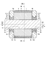
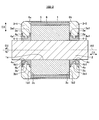
- FIG. 2 is a cross-sectional view of the rotor of the induction motor according to Embodiment 1 of the present invention.
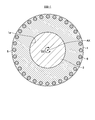
- 3 is a cross-sectional view taken along arrow III-III shown in FIG.
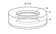
- FIG. 4 is a perspective view of the end ring shown in FIG.
- FIG. 5 is a perspective view of the reinforcing member shown in FIG.
- An induction motor 300 according to Embodiment 1 shown in FIG. 1 includes a stator 200 and a rotor 100-1 provided inside the stator 200.
- the stator 200 includes a cylindrical housing 210 and a stator core 220 provided inside the housing 210.
- the stator core 220 is configured by laminating a plurality of thin plates punched in an annular shape from a magnetic steel sheet base material (not shown) in the axial direction D1 of the central axis AX of the rotor core 1.
- the plurality of thin plates are fixed to each other by caulking, welding, or bonding.
- a plurality of coils 230 are arranged on the stator core 220.
- the coil end on one end side of the coil 230 in the axial direction D1 protrudes from the one end surface of the stator core 220 in the axial direction D1.
- the coil end on the other end side of the coil 230 in the axial direction D1 protrudes from the other end surface of the stator core 220 in the axial direction D1.
- the rotor 100-1 of the induction motor includes a cylindrical rotor core 1, a shaft 2, and one end portion in the axial direction D1 of the central axis AX of the rotor core 1. 1b1 and an annular end ring 3-1.
- the rotor 100-1 includes an annular end ring 3-2 provided at the other end 1b2 in the axial direction D1.
- the rotor 100-1 is provided between the inner peripheral portion 3a of the end ring 3-1 and the shaft 2, and the annular reinforcing member 4- in which the outer peripheral portion 4a is in contact with the inner peripheral portion 3a of the end ring 3-1. 1 is provided.
- the rotor 100-1 is provided between the inner peripheral portion 3a of the end ring 3-2 and the shaft 2, and the annular reinforcing member 4- in which the outer peripheral portion 4a is in contact with the inner peripheral portion 3a of the end ring 3-2. 2 is provided.
- the end ring 3-1 and the end ring 3-2 are referred to as end rings 3-1 and 3-2
- the reinforcing member 4-1 and the reinforcing member 4-2 are referred to as reinforcing members 4-1 and 4-2.
- the end rings 3-1 and 3-2 each include an annular first protrusion 3b provided on each inner peripheral portion 3a.
- the reinforcing members 4-1 and 4-2 are each provided with an annular first groove portion 4 b on each outer peripheral portion 4 a.
- the 1st groove part 4b is a shape where the 1st projection part 3b fits.
- the outer diameter of the first groove 4b is equal to the inner diameter of the first protrusion 3b.
- the width of the first groove 4b in the axial direction D1 is equal to the width of the first protrusion 3b in the axial direction D1.
- the rotor core 1 is configured by laminating a plurality of thin plates punched in an annular shape from a magnetic steel base material (not shown) in the axial direction D1.
- the plurality of thin plates are fixed to each other by caulking, welding, or bonding.
- the rotor core 1 is provided near the outer peripheral surface of the rotor core 1, and a plurality of core slots 5 arranged in the direction D2 around the central axis AX, and a conductor bar 6 provided in each of the plurality of core slots 5.
- Each of the plurality of core slots 5 extends in the axial direction D1 and penetrates from one end 1b1 of the rotor core 1 to the other end 1b2.
- the plurality of core slots 5 provided in the rotor core 1 are each skewed in the direction D2 around the axis.
- One end portion 6a in the axial direction D1 of the conductor bar 6 provided in the core slot 5 is connected to the end portion 3c on the rotor core 1 side of the end ring 3-1.
- the other end 6b in the axial direction D1 of the conductor bar 6 provided in the core slot 5 is connected to the end 3c on the rotor core 1 side of the end ring 3-2.
- Examples of the material of the end ring 3-1, the end ring 3-2 and the conductor bar 6 include conductor materials such as aluminum, aluminum alloy, copper or copper alloy.
- End rings 3-1 and 3-2 are formed by die casting using the conductor material.
- the end rings 3-1 and 3-2 have the same outer diameter as that of the rotor core 1.
- the inner peripheral portion 3a of the end ring 3-1 is in contact with the outer peripheral portion 4a of the reinforcing member 4-1.
- the inner peripheral portion 3a of the end ring 3-2 is in contact with the outer peripheral portion 4a of the reinforcing member 4-2.
- the centrifugal force acting on the object depends not only on the object radius and angular velocity but also on the object mass.
- the reinforcing members 4-1 and 4-2 need to be difficult to be deformed by the centrifugal force in order to suppress the deformation of the end rings 3-1 and 3-2 due to the centrifugal force and thermal expansion. Therefore, a material having a higher tensile strength per unit mass than the material of the end rings 3-1 and 3-2 is used for the reinforcing members 4-1 and 4-2.
- examples of the material of the reinforcing members 4-1, 4-2 include iron, titanium, or carbon fiber reinforced plastic.
- the reinforcing members 4-1 and 4-2 are each provided with a through hole 4c.
- the shaft 2 passes through the through holes 4 c of the reinforcing members 4-1 and 4-2 and the through holes 1 a of the rotor core 1.
- the reinforcing member 4-1 is attached to one end 1b1 of the rotor core 1, and the reinforcing member 4-2 is attached to the other end 1b2 of the rotor core 1.
- end rings 3-1 and 3-2 are formed by die casting using a conductive material, so that the reinforcing members 4-1 and 4 are in a state where the first protrusion 3b is fitted in the first groove 4b.
- end rings 3-1 and 3-2 are integrally molded.
- the state in which the reinforcing members 4-1 and 4-2 and the end rings 3-1 and 3-2 are integrally molded is in the first groove portion 4b of the reinforcing members 4-1 and 4-2.
- first protrusions 3b of the end rings 3-1 and 3-2 are fitted in contact with each other. That is, it means a state in which the first protrusion 3b is fitted in the first groove 4b.
- the through hole 4c of the reinforcing member 4-1, the through hole 4c of the reinforcing member 4-2, and the through hole 1a of the rotor core 1 are finished to the same size, and the inside of these through holes 4c and the through holes 1a is finished.
- the shaft 2 is tightly fitted to the shaft. In the first embodiment, the shaft 2 is shrink-fitted inside the through hole 4c and the through hole 1a.
- the reinforcing members 4-1 and 4-2 and the end rings 3-1 and 3-2 are integrally formed, so that the reinforcing members 4-1 and 4-2 and the end rings 3-1 and 3-2 are individually formed. Compared with the case of assembling to the shaft 2, the time for assembling the reinforcing members 4-1 and 4-2 and the end rings 3-1 and 3-2 to the shaft 2 is shortened. In addition, by reinforcing the reinforcing members 4-1, 4-2 and the end rings 3-1, 3-2 to the shaft 2, the reinforcing members 4-1, 4-2 have through holes as compared with the case where the reinforcing members 4-1, 4-2 are not shrink-fitted.
- the frictional force between the inner periphery of the hole 4c and the outer periphery of the shaft 2 is increased.
- This frictional force suppresses the movement of the reinforcing members 4-1 and 4-2 in the axial direction D 1 when the rotor 100-1 rotates at high speed and during thermal expansion.
- the reinforcing effect of the end rings 3-1 and 3-2 by the reinforcing members 4-1 and 4-2 is enhanced as compared with the case where shrink fitting is not performed.
- the reinforcing effect is an effect in which the reinforcing members 4-1 and 4-2 suppress deformation of the end rings 3-1 and 3-2 caused by centrifugal force and thermal expansion.
- FIG. 6 is a cross-sectional view of a comparative example for the rotor of the induction motor according to Embodiment 1 of the present invention. Differences between the rotor 100A shown in FIG. 6 and the rotor 100-1 shown in FIG. 2 are as follows. (1) The rotor 100A includes end rings 3-1A and 3-2A instead of the end rings 3-1 and 3-2 shown in FIG. The first protrusion 3b shown in FIG. 2 is not provided on the inner periphery 3a of the end rings 3-1A and 3-2A.
- the rotor 100A includes reinforcing members 4-1A and 4-2A instead of the reinforcing members 4-1 and 4-2 shown in FIG.
- the first groove 4b shown in FIG. 2 is not provided on the outer peripheral portion 4a of the reinforcing members 4-1A and 4-2A.
- the outer diameters of the outer peripheral portions 4a of the reinforcing member 4-1A and the reinforcing member 4-2A are equal to the inner diameters of the inner peripheral portions 3a of the end ring 3-1A and the end ring 3-2A.
- the widths of the reinforcing member 4-1A and the reinforcing member 4-2A in the axial direction D1 are equal to the widths of the end ring 3-1A and the end ring 3-2A in the axial direction D1, respectively.
- the reinforcing member 4-1A is attached to one end 1b1 of the rotor core 1, and the reinforcing member 4-2A is attached to the other end 1b2 of the rotor core 1.
- the end rings 3-1A and 3-2A are formed by die casting using a conductive material, whereby the end ring 3-1A and the reinforcing member 4-1A are integrally molded, and the end ring 3-2A and the reinforcing member are formed.
- 4-2A is integrally molded.
- the through hole 4c of the reinforcing member 4-1A, the through hole 4c of the reinforcing member 4-2A, and the through hole 1a of the rotor core 1 are finished to the same dimensions, and the inside of these through holes 4c and the through holes 1a is finished.
- the shaft 2 is shrink fitted.
- FIG. 7 is a diagram showing how the end ring is deformed when the rotor of the comparative example shown in FIG. 6 rotates.
- the outer shape of the end ring 3-1A when the rotor 100A is stopped is indicated by a solid line
- the outer shape of the end ring 3-1A deformed when the rotor 100A is rotating at a high speed is indicated by a dotted line. Indicated.
- the outer peripheral portion 4a of the reinforcing member 4-1A comes into contact with the inner peripheral portion 3a of the end ring 3-1A, and the reinforcing member 4-1A A frictional force is generated between the outer peripheral portion 4a and the inner peripheral portion 3a of the end ring 3-1A.
- This frictional force serves to suppress the deformation of the end ring 3-1A during rotation and thermal expansion of the rotor 100A.
- a force spreading outward in the radial direction D3 acts on the end ring 3-1A.
- the rotational speed of the rotor 100A increases, the amount of deformation of the end ring 3-1A increases, so that the stress amplitude generated in the end ring 3-1A becomes larger than when the rotational speed of the rotor 100A is low.
- the connection point between the end ring 3-1A and the conductor bar 6 has a stress caused by centrifugal force and thermal expansion. Therefore, metal fatigue at the connection point proceeds.
- the inner and outer diameters of the end ring 3-1A are repeatedly expanded and contracted, so that metal fatigue in the end ring 3-1A also proceeds. Therefore, the rotor 100A may need to be replaced in a period shorter than the design life.
- FIG. 8 is a diagram showing a state where the end ring is deformed when the rotor of the induction motor according to Embodiment 1 of the present invention rotates.
- the outer shape of the end ring 3-1 when the rotor 100-1 is stopped is indicated by a solid line, and the end ring 3-1 deformed when the rotor 100-1 rotates at high speed is shown. Indicated by dotted lines.
- the first protrusion 3b and the first groove 4b are integrally molded, and the first protrusion 3b has a fitting structure that fits into the first groove 4b.
- the contact area between the inner peripheral portion 3a of the end ring 3-1 and the outer peripheral portion 4a of the reinforcing member 4-1 is larger than that of the rotor 100A shown in FIG.
- the frictional force between the peripheral portion 3a and the outer peripheral portion 4a of the reinforcing member 4-1 is higher than that of the rotor 100A shown in FIG.
- the end ring 3-1 moves in the axial direction D1
- the first protrusion 3b is caught in the first groove 4b. Therefore, the deformation amount of the end ring 3-1 in the axial direction D1 and the radial direction D3 is smaller than that of the rotor 100A shown in FIG. Therefore, in the first embodiment, the reinforcing effect of the end rings 3-1 and 3-2 by the reinforcing members 4-1 and 4-2 is enhanced as compared with the rotor 100A shown in FIG. -2 is reduced, and the fatigue life of the end rings 3-1 and 3-2 can be improved.
- the outer ring portion of the reinforcing member does not undergo plastic deformation unlike the conventional rotor shown in Patent Document 1, and the end ring A decrease in the reinforcing effect due to 3-1 and 3-2 is suppressed, and a decrease in the life of the rotor 100-1 is suppressed.
- one fitting structure described above is provided at each of both end portions of the shaft 2.
- the fitting structure has two fitting structures at each of both end portions of the shaft 2. Two or more may be provided.
- a fitting structure is provided at each of both ends of the shaft 2.
- a fitting structure may be provided only at the end. Even in such a configuration, the effect of suppressing the deformation of the end ring 3-1 or the end ring 3-2 can be obtained at least in the relevant portion.
- the first groove 4b and the first protrusion 3b are formed in an annular shape, but the first groove 4b is formed of the reinforcing members 4-1, 4. -2 is configured as a plurality of depressions arranged in the axial direction D2, and the first protrusion 3b is configured as a plurality of projections arranged in the axial direction D2 in the end rings 3-1 and 3-2. May be.
- the first groove 4b and the first protrusion 3b are provided in an annular shape, the deformation of the end rings 3-1 and 3-2 is uniformly suppressed in the axial direction D2. The effect of improving the lifetime of ⁇ 1 is most obtained.
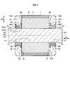
- FIG. FIG. 9 is a cross-sectional view of the rotor of the induction motor according to Embodiment 2 of the present invention. Differences between the rotor 100-1 according to the first embodiment and the rotor 100-2 according to the second embodiment are as follows. (1) In the rotor 100-2, each of the end rings 3-1 and 3-2 includes a plurality of first protrusions 3b. The plurality of first protrusions 3b included in the end ring 3-1 are provided on the inner peripheral portion 3a of the end ring 3-1, apart from each other in the axial direction D1.
- each of the reinforcing members 4-1 and 4-2 includes a plurality of first groove portions 4b.
- the plurality of first grooves 4b included in the reinforcing member 4-1 are provided on the outer peripheral portion 4a of the reinforcing member 4-1, apart from each other in the axial direction D1.
- the plurality of first groove portions 4b included in the reinforcing member 4-2 are provided on the outer peripheral portion 4a of the reinforcing member 4-2 so as to be separated from each other in the axial direction D1.
- End rings 3-1 and 3-2 are formed by die casting using a conductive material. Thereby, the end rings 3-1 and 3-2 and the reinforcing member 4-1 are integrally formed.
- the plurality of first protrusions 3b have a fitting structure that fits into the first groove 4b.
- the contact area between the inner peripheral portion 3a of the end ring 3-1 and the outer peripheral portion 4a of the reinforcing member 4-1 is larger than that in the first embodiment, and the inner periphery of the end rings 3-1 and 3-2 is increased.
- the frictional force between the portion 3a and the outer peripheral portion 4a of the reinforcing members 4-1, 4-2 is increased as compared with the first embodiment.
- the deformation amount of the end rings 3-1 and 3-2 in the axial direction D1 and the radial direction D3 is smaller than that in the first embodiment. Therefore, according to the second embodiment, the fatigue life of the end rings 3-1 and 3-2 can be further improved.
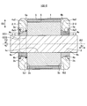
- FIG. FIG. 10 is a cross-sectional view of the rotor of the induction motor according to Embodiment 3 of the present invention. Differences between the rotor 100-1 according to the first embodiment and the rotor 100-3 according to the third embodiment are as follows. (1) The first protrusion 3b of the rotor 100-3 is provided with an annular second protrusion 3b1 on the inner periphery 3a1 of the first protrusion 3b. (2) In the first groove 4b of the rotor 100-3, an annular second groove 4b1 is provided on the outer peripheral part 4a1 of the first groove 4b.
- the width of the second protrusion 3b1 in the axial direction D1 is narrower than the width of the first protrusion 3b in the axial direction D1, and the width of the second groove 4b1 in the axial direction D1 is the first width in the axial direction D1. It is narrower than the width of the groove 4b.
- End rings 3-1 and 3-2 are formed by die casting using a conductive material.
- the first protrusion 3b and the first groove 4b are integrally molded, and the second protrusion 3b1 and the second groove 4b1 are integrally formed.
- the first protrusion 3b is fitted into the first groove 4b, and the second protrusion 3b1 is fitted into the second groove 4b1.
- the contact area between the inner peripheral portion 3a of the end rings 3-1 and 3-2 and the outer peripheral portion 4a of the reinforcing members 4-1 and 4-2 becomes larger than that of the first embodiment, and the end ring 3-
- the frictional force between the inner peripheral portion 3a of 1 and 3-2 and the outer peripheral portion 4a of the reinforcing members 4-1 and 4-2 is increased as compared with the first embodiment.
- the first protrusion 3b is caught in the first groove 4b
- the second protrusion 3b1 is caught in the second groove 4b1. Therefore, the deformation amount of the end rings 3-1 and 3-2 in the axial direction D1 and the radial direction D3 is further reduced as compared with the first embodiment. Therefore, according to the third embodiment, the fatigue life of the end rings 3-1 and 3-2 can be further improved.
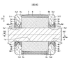
- FIG. FIG. 11 is a cross-sectional view of the rotor of the induction motor according to Embodiment 4 of the present invention.
- Differences between the rotor 100-1 according to the first embodiment and the rotor 100-4 according to the fourth embodiment are as follows.
- the reinforcing members 4-1 and 4-2 of the rotor 100-4 have the outer diameter OD1 of the outer peripheral portion 4a2 on the rotor core 1 side of the first groove portion 4b in the respective outer peripheral portions 4a.
- the outer diameter OD2 of the outer peripheral portion 4a3 opposite to the rotor core 1 is larger than the first groove portion 4b.
- the width in the axial direction D1 of the outer peripheral portion 4a2 is equal to the width in the axial direction D1 of the outer peripheral portion 4a3.
- the end rings 3-1 and 3-2 are thermally expanded and deformed, and then the end rings 3-1 and 3-2 are thermally contracted to return to the initial positions before the thermal expansion.
- the thermal expansion and thermal contraction of the end ring 3-1 in the axial direction D1 will be considered.
- the end ring 3-1 expands outward in the axial direction D1 during thermal expansion, and contracts toward the rotor core 1 in the axial direction D1 during thermal contraction. Further, consider the force that the end ring 3-1 gives to the reinforcing member 4-1.
- stress is also applied between the reinforcement member 4-1 and the shaft 2 that are shrink-fitted.
- the end ring 3-1 thermally expands on the side wall opposite to the rotor core 1.
- a force is applied.
- the stress that the end ring 3-1 thermally expands and pushes the reinforcing member 4-1 outward in the axial direction D1 can be reduced. it can.
- a force is applied to the side wall near the rotor core 1 among the two side walls described above toward the rotor core 1 in the axial direction D1.
- the outer diameter dimension OD1 is larger than the outer diameter dimension OD2, it is possible to reduce the stress by which the end ring 3-1 is thermally contracted and the reinforcing member 4-1 is pulled back to the rotor core 1 side. That is, the stress that is shifted toward the opposite side of the rotor core 1 from the position when the reinforcing member 4-1 is shrink-fitted onto the shaft 2 is applied to the reinforcing member 4-1 at the time of thermal expansion of the end ring 3-1. Work. On the other hand, stress that is shifted toward the rotor core 1 from the position when the reinforcing member 4-1 is shrink-fitted to the shaft 2 acts on the reinforcing member 4-1 when the end ring 3-1 is thermally contracted.
- the reinforcing member 4-1 since the force at the time of thermal expansion is large, if the reinforcing member 4-1 is shifted from the above position to the opposite side of the rotor core 1, the reinforcing member 4-1 returns to its original position at the time of thermal contraction. Is difficult to return, and the integrally formed end ring 3-1 is also difficult to return to its original shape. As a result, the end ring 3-1 is deformed, leading to a reduction in the life of the rotor.
- the stress acting between the reinforcing member 4-1 and the shaft 2 when the end ring 3-1 is thermally contracted causes the reinforcing member when the end ring 3-1 is thermally expanded. Since it is larger than the stress acting between 4-1 and the shaft 2, deformation of the reinforcing member 4-1 and the end ring 3-1 can be suppressed. The same applies to the end ring 3-2 and the reinforcing member 4-2.
- Embodiment 4 can be combined with any of Embodiments 1 to 3.
- FIG. FIG. 12 is a cross-sectional view of the rotor of the induction motor according to Embodiment 5 of the present invention.
- Differences between the rotor 100-1 according to the first embodiment and the rotor 100-5 according to the fifth embodiment are as follows.
- Reinforcing members 4-1 and 4-2 of the rotor 100-5 have outer diameters of the outer peripheral portion 4a3 on the opposite side of the rotor core 1 from the first groove portion 4b of the outer peripheral portions 4a
- the dimension OD2 is larger than the outer diameter dimension OD1 of the outer peripheral part 4a2 on the rotor core 1 side than the first groove part 4b.
- the width in the axial direction D1 of the outer peripheral portion 4a2 is equal to the width in the axial direction D1 of the outer peripheral portion 4a3.
- the centrifugal force acts on the end rings 3-1 and 3-2 or the end rings 3-1 and 3-2 are heated.
- the amount of deformation of the end rings 3-1 and 3-2 in the direction opposite to the direction toward the center of the rotor core 1 when expanded can be suppressed. Therefore, the reinforcing effect of the end rings 3-1 and 3-2 can be further enhanced.
- the fifth embodiment can be combined with any of the first to third embodiments.
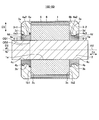
- FIG. 13 is a view showing a first modification of the rotor shown in FIG. Differences between the rotor 100-1 shown in FIG. 2 and the rotor 100-6A shown in FIG. 13 are as follows. (1) The first groove 4b of the rotor 100-6A includes a first inclined surface 4d at the end of the first groove 4b opposite to the rotor core 1. (2) The first protrusion 3b of the rotor 100-6A includes a second inclined surface 3d at the end of the first protrusion 3b opposite to the rotor core 1. The second inclined surface 3d is in contact with the first inclined surface 4d.
- the first inclined surface 4d of the reinforcing member 4-1 has a shape that widens from the reinforcing member 4-2 toward the reinforcing member 4-1, in the axial direction D1.
- the first inclined surface 4d of the reinforcing member 4-2 has a shape that widens from the reinforcing member 4-1 toward the reinforcing member 4-2 in the axial direction D1.
- the second inclined surface 3d of the end ring 3-1 has a shape that widens from the end ring 3-2 toward the end ring 3-1 in the axial direction D1.
- the second inclined surface 3d of the end ring 3-2 has a shape that widens from the end ring 3-1 toward the end ring 3-2 in the axial direction D1.
- FIG. 14 is a view showing a first modification of the rotor shown in FIG. Differences between the rotor 100-2 shown in FIG. 9 and the rotor 100-6B shown in FIG. 14 are as follows. (1) In the rotor 100-6B, each of the plurality of first grooves 4b includes a first inclined surface 4d at the end of the first groove 4b opposite to the rotor core 1. (2) In the rotor 100-6B, each of the plurality of first protrusions 3b includes the second inclined surface 3d at the end of the first protrusion 3b opposite to the rotor core 1. The second inclined surface 3d is in contact with the first inclined surface 4d.
- FIG. 15 is a view showing a first modification of the rotor shown in FIG. Differences between the rotor 100-3 shown in FIG. 10 and the rotor 100-6C shown in FIG. 15 are as follows. (1) In the rotor 100-6C, each of the first groove portion 4b and the second groove portion 4b1 is provided at the end of the first groove portion 4b and the second groove portion 4b1 on the opposite side to the rotor core 1. 1 d of inclined surfaces. (2) In the rotor 100-6C, each of the first protrusion 3b and the second protrusion 3b1 is opposite to the rotor core 1 of the first protrusion 3b and the second protrusion 3b1. A second inclined surface 3d is provided at the end. The second inclined surface 3d is in contact with the first inclined surface 4d.
- FIG. 16 is a view showing a first modification of the rotor shown in FIG.
- the difference between the rotor 100-4 shown in FIG. 11 and the rotor 100-6D shown in FIG. 16 is as follows.
- the first groove 4b of the rotor 100-6D includes a first inclined surface 4d at the end of the first groove 4b opposite to the rotor core 1.
- the first protrusion 3b of the rotor 100-6D includes a second inclined surface 3d at the end of the first protrusion 3b opposite to the rotor core 1.
- the second inclined surface 3d is in contact with the first inclined surface 4d.
- FIG. 17 is a view showing a first modification of the rotor shown in FIG. Differences between the rotor 100-5 shown in FIG. 12 and the rotor 100-6E shown in FIG. 17 are as follows. (1) The first groove 4b of the rotor 100-6E includes a first inclined surface 4d at the end of the first groove 4b opposite to the rotor core 1. (2) The first protrusion 3b of the rotor 100-6E includes a second inclined surface 3d at the end of the first protrusion 3b opposite to the rotor core 1. The second inclined surface 3d is in contact with the first inclined surface 4d.
- the effect of suppressing deformation during rotation due to the frictional force between the inner peripheral portion 3a of the end rings 3-1 and 3-2 and the outer peripheral portion 4a of the reinforcing members 4-1 and 4-2 is an angle with respect to the central axis AX.
- the surface with is higher. Therefore, in order to increase the effect of suppressing deformation during rotation, it is desirable to increase the contact area having an angle with respect to the central axis AX.
- the first grooves 4b are provided with the first inclined surfaces 4d, and the first protrusions 3b are provided with the second inclined surfaces 3d, whereby the end rings 3-1 and 3-2 are provided.
- the area of the surface having an angle with the central axis AX is larger than in the first to fifth embodiments, and the end ring
- the frictional force between the inner peripheral portion 3a of 3-1 and 3-2 and the outer peripheral portion 4a of the reinforcing members 4-1 and 4-2 is increased as compared with the first to fifth embodiments.
- the reinforcing effect of the end rings 3-1 and 3-2 can be further enhanced.
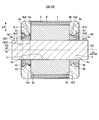
- FIG. 18 is a diagram showing a second modification of the rotor shown in FIG. Differences between the rotor 100-1 shown in FIG. 2 and the rotor 100-7A shown in FIG. 18 are as follows. (1) The first groove 4b of the rotor 100-7A includes a first inclined surface 4d1 at the end of the first groove 4b on the rotor core 1 side. (2) The first protrusion 3b of the rotor 100-7A includes a second inclined surface 3d1 at the end of the first protrusion 3b on the rotor core 1 side. The second inclined surface 3d1 is in contact with the first inclined surface 4d1.
- the first inclined surface 4d1 of the reinforcing member 4-1 has a shape that widens from the reinforcing member 4-1 toward the reinforcing member 4-2 in the axial direction D1.
- the first inclined surface 4d1 of the reinforcing member 4-2 has a shape that widens from the reinforcing member 4-2 toward the reinforcing member 4-1, in the axial direction D1.
- the second inclined surface 3d1 of the end ring 3-1 has a shape that widens from the end ring 3-1 toward the end ring 3-2 in the axial direction D1.
- the second inclined surface 3d1 of the end ring 3-2 has a shape that widens from the end ring 3-2 toward the end ring 3-1 in the axial direction D1.
- FIG. 19 is a view showing a second modification of the rotor shown in FIG. Differences between the rotor 100-2 shown in FIG. 9 and the rotor 100-7B shown in FIG. 19 are as follows. (1) In the rotor 100-7B, each of the plurality of first grooves 4b includes the first inclined surface 4d1 at the end of the first groove 4b on the rotor core 1 side. (2) In the rotor 100-7B, each of the plurality of first protrusions 3b includes the second inclined surface 3d1 at the end of the first protrusion 3b on the rotor core 1 side. The second inclined surface 3d1 is in contact with the first inclined surface 4d1.
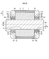
- FIG. 20 is a diagram showing a second modification of the rotor shown in FIG. Differences between the rotor 100-3 shown in FIG. 10 and the rotor 100-7C shown in FIG. 20 are as follows. (1) In the rotor 100-7C, each of the first groove portion 4b and the second groove portion 4b1 has a first groove portion at the end of the first groove portion 4b and the second groove portion 4b1 on the rotor core 1 side. The inclined surface 4d1 is provided. (2) In the rotor 100-7C, each of the first protrusion 3b and the second protrusion 3b1 is the end of the first protrusion 3b and the second protrusion 3b1 on the rotor core 1 side. The part is provided with a second inclined surface 3d1. The second inclined surface 3d1 is in contact with the first inclined surface 4d1.
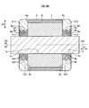
- FIG. 21 is a diagram showing a second modification of the rotor shown in FIG.
- the difference between the rotor 100-4 shown in FIG. 11 and the rotor 100-7D shown in FIG. 21 is as follows.
- the first groove 4b of the rotor 100-7D includes a first inclined surface 4d1 at the end of the first groove 4b on the rotor core 1 side.
- the first protrusion 3b of the rotor 100-7D includes a second inclined surface 3d1 at the end of the first protrusion 3b on the rotor core 1 side.
- the second inclined surface 3d1 is in contact with the first inclined surface 4d1.
- FIG. 22 is a view showing a second modification of the rotor shown in FIG. Differences between the rotor 100-5 shown in FIG. 12 and the rotor 100-7E shown in FIG. 22 are as follows. (1) The first groove 4b of the rotor 100-7E includes a first inclined surface 4d1 at the end of the first groove 4b on the rotor core 1 side. (2) The first protrusion 3b of the rotor 100-7E includes a second inclined surface 3d1 at the end of the first protrusion 3b on the rotor core 1 side. The second inclined surface 3d1 is in contact with the first inclined surface 4d1.
- the end rings 3-1 and 3-2 are provided.
- the contact area between the inner peripheral portion 3a of the reinforcing member 4-1 and the outer peripheral portion 4a of the reinforcement member 4-1 and 4-2 is wider than those of the first to fifth embodiments, and the inner peripheral portion 3a of the end rings 3-1 and 3-2 And the frictional force between the outer peripheral portions 4a of the reinforcing members 4-1 and 4-2 are higher than those in the first to fifth embodiments.
- the reinforcing effect of the end rings 3-1 and 3-2 can be further enhanced.
- FIG. 23 is a view showing a third modification of the rotor shown in FIG.
- the first groove 4b includes the first inclined surface 4d of the sixth embodiment and the first inclined surface 4d1 of the seventh embodiment.
- the first protrusion 3b includes the second inclined surface 3d of the sixth embodiment and the second inclined surface 3d1 of the seventh embodiment.
- FIG. 24 is a view showing a third modification of the rotor shown in FIG.
- each of the plurality of first grooves 4b includes the first inclined surface 4d of the sixth embodiment and the first inclined surface 4d1 of the seventh embodiment.
- each of the plurality of first protrusions 3b includes the second inclined surface 3d of the sixth embodiment and the second inclined surface 3d1 of the seventh embodiment.
- FIG. 25 is a view showing a third modification of the rotor shown in FIG.
- each of the first groove 4b and the second groove 4b1 includes the first inclined surface 4d of the sixth embodiment and the first inclined surface 4d1 of the seventh embodiment. Is provided.
- each of the first protrusion 3b and the second protrusion 3b1 includes the second inclined surface 3d of the sixth embodiment and the second inclined surface 3d1 of the seventh embodiment.
- FIG. 26 is a view showing a third modification of the rotor shown in FIG.
- the first groove 4b includes the first inclined surface 4d of the sixth embodiment and the first inclined surface 4d1 of the seventh embodiment.
- the first protrusion 3b includes the second inclined surface 3d of the sixth embodiment and the second inclined surface 3d1 of the seventh embodiment.
- FIG. 27 is a view showing a third modification of the rotor shown in FIG.
- the first groove 4b includes the first inclined surface 4d of the sixth embodiment and the first inclined surface 4d1 of the seventh embodiment.
- the first protrusion 3b includes the second inclined surface 3d of the sixth embodiment and the second inclined surface 3d1 of the seventh embodiment.
- the first groove 4b includes the first inclined surface 4d and the first inclined surface 4d1, and the first protrusion 3b has the second inclined surface 3d and the second inclined surface 3d1.
- the contact area between the inner peripheral portion 3a of the end rings 3-1 and 3-2 and the outer peripheral portion 4a of the reinforcing members 4-1 and 4-2 becomes wider than in the first to fifth embodiments.
- the frictional force between the inner peripheral portion 3a of the end rings 3-1 and 3-2 and the outer peripheral portion 4a of the reinforcing members 4-1 and 4-2 is increased as compared with the first to fifth embodiments. As a result, the reinforcing effect of the end rings 3-1 and 3-2 can be further enhanced.
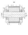
- FIG. 28 is a diagram showing a fourth modification of the rotor shown in FIG. A rotor 100-9 shown in FIG. 28 includes reinforcing members 4-1B and 4-2B instead of the reinforcing members 4-1 and 4-2, and end rings 3 instead of the end rings 3-1 and 3-2. -1B and 3-2B.
- the reinforcing member 4-1B includes a first annular portion 41 provided near the rotor core 1 of the reinforcing member 4-1B, and a second annular portion provided near the rotor core 1 of the reinforcing member 4-1B.
- the annular portion 42 is provided.
- the outer diameter of the second annular portion 42 is smaller than the outer diameter of the first annular portion 41. Therefore, a step portion is formed between the first annular portion 41 and the second annular portion 42.
- the first reinforcing member 4-2B is configured similarly to the reinforcing member 4-1B.
- the inner peripheral part 3a of the end ring 3-1B formed by die casting is in contact with the outer peripheral part 4a of each of the first annular part 41 and the second annular part 42.
- the end 3e of the first protrusion 3b opposite to the rotor core 1 is the end 4e of the first annular portion 41 on the rotor core 1 side, that is, the first annular portion 41 and the first annular portion 41. It contacts the step portion between the two annular portions 42. That is, the first protrusion 3b is fitted in the stepped portion.
- the configuration described in the above embodiment shows an example of the contents of the present invention, and can be combined with another known technique, and can be combined with other configurations without departing from the gist of the present invention. It is also possible to omit or change the part.
Landscapes
- Engineering & Computer Science (AREA)
- Power Engineering (AREA)
- Induction Machinery (AREA)
- Iron Core Of Rotating Electric Machines (AREA)
Abstract
Description
図1は本発明の実施の形態1に係る誘導電動機の断面図である。図2は本発明の実施の形態1に係る誘導電動機の回転子の断面図である。図3は図2に示すIII-III矢視断面図である。図4は図2に示すエンドリングの斜視図である。図5は図2に示す補強部材の斜視図である。
(1)回転子100Aは、図2に示すエンドリング3-1,3-2の代わりにエンドリング3-1A,3-2Aを備える。エンドリング3-1A,3-2Aの内周部3aには、図2に示す第1の突起部3bが設けられていない。
(2)回転子100Aは、図2に示す補強部材4-1,4-2の代わりに補強部材4-1A,4-2Aを備える。補強部材4-1A,4-2Aの外周部4aには、図2に示す第1の溝部4bが設けられていない。
図9は本発明の実施の形態2に係る誘導電動機の回転子の断面図である。実施の形態1に係る回転子100-1と実施の形態2に係る回転子100-2との相違点は以下の通りである。
(1)回転子100-2は、エンドリング3-1,3-2のそれぞれが複数の第1の突起部3bを備える。エンドリング3-1が備える複数の第1の突起部3bは、軸線方向D1に互いに離れてエンドリング3-1の内周部3aに設けられる。エンドリング3-2が備える複数の第1の突起部3bは、軸線方向D1に互いに離れてエンドリング3-2の内周部3aに設けられる。
(2)回転子100-2は、補強部材4-1,4-2のそれぞれが複数の第1の溝部4bを備える。補強部材4-1が備える複数の第1の溝部4bは、軸線方向D1に互いに離れて補強部材4-1の外周部4aに設けられる。補強部材4-2が備える複数の第1の溝部4bは、軸線方向D1に互いに離れて補強部材4-2の外周部4aに設けられる。
図10は本発明の実施の形態3に係る誘導電動機の回転子の断面図である。実施の形態1に係る回転子100-1と実施の形態3に係る回転子100-3との相違点は以下の通りである。
(1)回転子100-3の第1の突起部3bには、第1の突起部3bの内周部3a1に環状の第2の突起部3b1が設けられる。
(2)回転子100-3の第1の溝部4bには、第1の溝部4bの外周部4a1に環状の第2の溝部4b1が設けられる。
図11は本発明の実施の形態4に係る誘導電動機の回転子の断面図である。実施の形態1に係る回転子100-1と実施の形態4に係る回転子100-4との相違点は以下の通りである。
(1)回転子100-4の補強部材4-1,4-2は、それぞれの外周部4aの内、第1の溝部4bよりも回転子鉄心1側の外周部4a2の外径寸法OD1が、第1の溝部4bよりも回転子鉄心1とは反対側の外周部4a3の外径寸法OD2よりも大きい。外周部4a2の軸線方向D1における幅は、外周部4a3の軸線方向D1における幅と等しい。
図12は本発明の実施の形態5に係る誘導電動機の回転子の断面図である。実施の形態1に係る回転子100-1と実施の形態5に係る回転子100-5との相違点は以下の通りである。
(1)回転子100-5の補強部材4-1,4-2は、それぞれの外周部4aの内、第1の溝部4bよりも回転子鉄心1とは反対側の外周部4a3の外径寸法OD2が、第1の溝部4bよりも回転子鉄心1側の外周部4a2の外径寸法OD1よりも大きい。外周部4a2の軸線方向D1における幅は、外周部4a3の軸線方向D1における幅と等しい。
実施の形態6では実施の形態1から5の第1の変形例を説明する。図13は図2に示す回転子の第1の変形例を示す図である。図2に示す回転子100-1と図13に示す回転子100-6Aとの相違点は以下の通りである。
(1)回転子100-6Aの第1の溝部4bは、第1の溝部4bの回転子鉄心1とは反対側の端部に第1の傾斜面4dを備える。
(2)回転子100-6Aの第1の突起部3bは、第1の突起部3bの回転子鉄心1とは反対側の端部に第2の傾斜面3dを備える。第2の傾斜面3dは第1の傾斜面4dと接する。
(1)回転子100-6Bは、複数の第1の溝部4bのそれぞれが、第1の溝部4bの回転子鉄心1とは反対側の端部に第1の傾斜面4dを備える。
(2)回転子100-6Bは、複数の第1の突起部3bのそれぞれが、第1の突起部3bの回転子鉄心1とは反対側の端部に第2の傾斜面3dを備える。第2の傾斜面3dは第1の傾斜面4dと接する。
(1)回転子100-6Cは、第1の溝部4b及び第2の溝部4b1のそれぞれが、第1の溝部4b及び第2の溝部4b1の回転子鉄心1とは反対側の端部に第1の傾斜面4dを備える。
(2)回転子100-6Cは、第1の突起部3b及び第2の突起部3b1のそれぞれが、第1の突起部3b及び第2の突起部3b1の回転子鉄心1とは反対側の端部に第2の傾斜面3dを備える。第2の傾斜面3dは第1の傾斜面4dと接する。
(1)回転子100-6Dの第1の溝部4bは、第1の溝部4bの回転子鉄心1とは反対側の端部に第1の傾斜面4dを備える。
(2)回転子100-6Dの第1の突起部3bは、第1の突起部3bの回転子鉄心1とは反対側の端部に第2の傾斜面3dを備える。第2の傾斜面3dは第1の傾斜面4dと接する。
(1)回転子100-6Eの第1の溝部4bは、第1の溝部4bの回転子鉄心1とは反対側の端部に第1の傾斜面4dを備える。
(2)回転子100-6Eの第1の突起部3bは、第1の突起部3bの回転子鉄心1とは反対側の端部に第2の傾斜面3dを備える。第2の傾斜面3dは第1の傾斜面4dと接する。
実施の形態7では実施の形態1から5の第2の変形例を説明する。図18は図2に示す回転子の第2の変形例を示す図である。図2に示す回転子100-1と図18に示す回転子100-7Aとの相違点は以下の通りである。
(1)回転子100-7Aの第1の溝部4bは、第1の溝部4bの回転子鉄心1側の端部に第1の傾斜面4d1を備える。
(2)回転子100-7Aの第1の突起部3bは、第1の突起部3bの回転子鉄心1側の端部に第2の傾斜面3d1を備える。第2の傾斜面3d1は第1の傾斜面4d1と接する。
(1)回転子100-7Bは、複数の第1の溝部4bのそれぞれが、第1の溝部4bの回転子鉄心1側の端部に第1の傾斜面4d1を備える。
(2)回転子100-7Bは、複数の第1の突起部3bのそれぞれが、第1の突起部3bの回転子鉄心1側の端部に第2の傾斜面3d1を備える。第2の傾斜面3d1は第1の傾斜面4d1と接する。
(1)回転子100-7Cは、第1の溝部4b及び第2の溝部4b1のそれぞれが、第1の溝部4b及び第2の溝部4b1のそれぞれの回転子鉄心1側の端部に第1の傾斜面4d1を備える。
(2)回転子100-7Cは、第1の突起部3b及び第2の突起部3b1のそれぞれが、第1の突起部3b及び第2の突起部3b1のそれぞれの回転子鉄心1側の端部に第2の傾斜面3d1を備える。第2の傾斜面3d1は第1の傾斜面4d1と接する。
(1)回転子100-7Dの第1の溝部4bは、第1の溝部4bの回転子鉄心1側の端部に第1の傾斜面4d1を備える。
(2)回転子100-7Dの第1の突起部3bは、第1の突起部3bの回転子鉄心1側の端部に第2の傾斜面3d1を備える。第2の傾斜面3d1は第1の傾斜面4d1と接する。
(1)回転子100-7Eの第1の溝部4bは、第1の溝部4bの回転子鉄心1側の端部に第1の傾斜面4d1を備える。
(2)回転子100-7Eの第1の突起部3bは、第1の突起部3bの回転子鉄心1側の端部に第2の傾斜面3d1を備える。第2の傾斜面3d1は第1の傾斜面4d1と接する。
実施の形態8では実施の形態1から5の第3の変形例を説明する。図23は図2に示す回転子の第3の変形例を示す図である。図23に示す回転子100-8Aは、第1の溝部4bが、実施の形態6の第1の傾斜面4dと実施の形態7の第1の傾斜面4d1とを備える。また回転子100-8Aは、第1の突起部3bが、実施の形態6の第2の傾斜面3dと実施の形態7の第2の傾斜面3d1とを備える。
Claims (10)
- 回転子鉄心と、
前記回転子鉄心を貫通するシャフトと、
前記回転子鉄心の端部に設けられる環状のエンドリングと、
前記シャフトと前記エンドリングの内周部との間に設けられ、外周部が前記エンドリングに接する環状の補強部材と
を備え、
前記エンドリングの内周部に設けられた第1の突起部が、前記補強部材の外周部に設けられた第1の溝部内に嵌められていることを特徴とする誘導電動機の回転子。 - 前記第1の突起部及び前記第1の溝部は、それぞれ環状に設けられていることを特徴とする請求項1に記載の誘導電動機の回転子。
- 前記エンドリングは、前記第1の突起部の内周部に設けられる第2の突起部を備え、
前記補強部材は、前記第1の溝部の外周部に設けられ前記第2の突起部が嵌まる第2の溝部を備え、
前記回転子鉄心の中心軸の軸線方向における前記第2の突起部の幅は、前記軸線方向における前記第1の突起部の幅よりも狭く、
前記軸線方向における前記第2の溝部の幅は、前記軸線方向における前記第1の溝部の幅よりも狭いことを特徴とする請求項1又は請求項2に記載の誘導電動機の回転子。 - 前記補強部材は、前記補強部材の外周部の内、前記第1の溝部よりも前記回転子鉄心側の外周部の外径寸法が、前記第1の溝部よりも前記回転子鉄心とは反対側の外周部の外径寸法よりも大きいことを特徴とする請求項1から請求項3の何れか一項に記載の誘導電動機の回転子。
- 前記補強部材は、前記補強部材の外周部の内、前記第1の溝部よりも前記回転子鉄心とは反対側の外周部の外径寸法が、前記第1の溝部よりも前記回転子鉄心側の外周部の外径寸法よりも大きいことを特徴とする請求項1から請求項3の何れか一項に記載の誘導電動機の回転子。
- 前記第1の溝部は、前記回転子鉄心の中心軸の軸線方向における前記第1の溝部の端部に第1の傾斜面を備え、
前記第1の突起部は、前記軸線方向における前記第1の突起部の端部に、前記第1の傾斜面と接する第2の傾斜面を備えることを特徴とする請求項1から請求項5の何れか一項に記載の誘導電動機の回転子。 - 回転子鉄心と、
前記回転子鉄心を貫通するシャフトと、
前記回転子鉄心の端部に設けられる環状のエンドリングと、
前記シャフトと前記エンドリングの内周部との間に設けられ、外周部が前記エンドリングに接する環状の補強部材と
を備え、
前記補強部材は、
前記補強部材の前記回転子鉄心とは反対寄りに設けられた第1の環状部と、
前記補強部材の前記回転子鉄心寄りに設けられ、外径が前記第1の環状部の外径より小さい第2の環状部と、
からなる段差部を有し、
前記エンドリングの内周部に設けられた第1の突起部が、前記段差部に嵌められていることを特徴とする誘導電動機の回転子。 - 前記第1の突起部、前記第1の環状部及び前記第2の環状部は、それぞれ環状に設けられていることを特徴とする請求項7に記載の誘導電動機の回転子。
- 前記エンドリング及び前記補強部材は、前記回転子鉄心の両側の端部に設けられることを特徴とする請求項1から請求項8の何れか一項に記載の誘導電動機の回転子。
- 請求項1から請求項9の何れか一項に記載の誘導電動機の回転子を備えた誘導電動機。
Priority Applications (6)
| Application Number | Priority Date | Filing Date | Title |
|---|---|---|---|
| KR1020177022066A KR20180044836A (ko) | 2016-08-23 | 2016-08-23 | 유도 전동기의 회전자 및 유도 전동기 |
| PCT/JP2016/074556 WO2018037486A1 (ja) | 2016-08-23 | 2016-08-23 | 誘導電動機の回転子及び誘導電動機 |
| DE112016007177.9T DE112016007177B4 (de) | 2016-08-23 | 2016-08-23 | Rotor für einen Asynchronmotor und Asynchronmotor |
| JP2017512400A JP6165385B1 (ja) | 2016-08-23 | 2016-08-23 | 誘導電動機の回転子及び誘導電動機 |
| CN201680010534.XA CN107980197B (zh) | 2016-08-23 | 2016-08-23 | 感应电动机的转子及感应电动机 |
| TW106123044A TWI637582B (zh) | 2016-08-23 | 2017-07-10 | 感應電動機之轉子及感應電動機 |
Applications Claiming Priority (1)
| Application Number | Priority Date | Filing Date | Title |
|---|---|---|---|
| PCT/JP2016/074556 WO2018037486A1 (ja) | 2016-08-23 | 2016-08-23 | 誘導電動機の回転子及び誘導電動機 |
Publications (1)
| Publication Number | Publication Date |
|---|---|
| WO2018037486A1 true WO2018037486A1 (ja) | 2018-03-01 |
Family
ID=59351365
Family Applications (1)
| Application Number | Title | Priority Date | Filing Date |
|---|---|---|---|
| PCT/JP2016/074556 Ceased WO2018037486A1 (ja) | 2016-08-23 | 2016-08-23 | 誘導電動機の回転子及び誘導電動機 |
Country Status (6)
| Country | Link |
|---|---|
| JP (1) | JP6165385B1 (ja) |
| KR (1) | KR20180044836A (ja) |
| CN (1) | CN107980197B (ja) |
| DE (1) | DE112016007177B4 (ja) |
| TW (1) | TWI637582B (ja) |
| WO (1) | WO2018037486A1 (ja) |
Cited By (1)
| Publication number | Priority date | Publication date | Assignee | Title |
|---|---|---|---|---|
| FR3086121A1 (fr) | 2018-09-19 | 2020-03-20 | Ge Energy Power Conversion Technology Limited | Rotor pour machine electrique asynchrone a arbre non traversant |
Families Citing this family (2)
| Publication number | Priority date | Publication date | Assignee | Title |
|---|---|---|---|---|
| DE102022202525A1 (de) | 2022-03-15 | 2023-09-21 | Zf Friedrichshafen Ag | Rotor für eine elektrische Maschine |
| DE102024121107A1 (de) * | 2024-07-24 | 2026-01-29 | Valeo Eautomotive Germany Gmbh | Rotor und elektrische Maschine mit verbesserter Rotorendplatte und Fahrzeug und Herstellungsverfahren dafür |
Citations (4)
| Publication number | Priority date | Publication date | Assignee | Title |
|---|---|---|---|---|
| JPS55127869A (en) * | 1979-03-22 | 1980-10-03 | Mitsubishi Electric Corp | Rotor of rotating electric machine |
| JPS5935554A (ja) * | 1982-08-18 | 1984-02-27 | Toshiba Corp | かご形誘導電動機 |
| JPH03289338A (ja) * | 1990-04-03 | 1991-12-19 | Fuji Electric Co Ltd | 回転電機の回転子 |
| WO2015188985A1 (de) * | 2014-06-11 | 2015-12-17 | Robert Bosch Gmbh | Elektrische asynchronmaschine mit innen liegendem stabilisierungsring für den kurzschlussring |
Family Cites Families (5)
| Publication number | Priority date | Publication date | Assignee | Title |
|---|---|---|---|---|
| JPH0777504B2 (ja) * | 1987-11-17 | 1995-08-16 | ファナック株式会社 | 高速インダクション型モータのロータ構造 |
| JP3219642B2 (ja) * | 1995-06-15 | 2001-10-15 | 株式会社東芝 | かご形回転子の製造方法 |
| JP5969525B2 (ja) | 2014-02-25 | 2016-08-17 | ファナック株式会社 | 端絡環を備える回転子、および電動機 |
| CN106134045B (zh) * | 2014-03-31 | 2018-10-12 | 三菱电机株式会社 | 笼型电动机的转子及笼型电动机 |
| CN204304648U (zh) * | 2014-12-18 | 2015-04-29 | 重庆赛力盟电机有限责任公司 | 中型异步电机转子压圈结构 |
-
2016
- 2016-08-23 WO PCT/JP2016/074556 patent/WO2018037486A1/ja not_active Ceased
- 2016-08-23 DE DE112016007177.9T patent/DE112016007177B4/de active Active
- 2016-08-23 JP JP2017512400A patent/JP6165385B1/ja active Active
- 2016-08-23 CN CN201680010534.XA patent/CN107980197B/zh active Active
- 2016-08-23 KR KR1020177022066A patent/KR20180044836A/ko not_active Ceased
-
2017
- 2017-07-10 TW TW106123044A patent/TWI637582B/zh active
Patent Citations (4)
| Publication number | Priority date | Publication date | Assignee | Title |
|---|---|---|---|---|
| JPS55127869A (en) * | 1979-03-22 | 1980-10-03 | Mitsubishi Electric Corp | Rotor of rotating electric machine |
| JPS5935554A (ja) * | 1982-08-18 | 1984-02-27 | Toshiba Corp | かご形誘導電動機 |
| JPH03289338A (ja) * | 1990-04-03 | 1991-12-19 | Fuji Electric Co Ltd | 回転電機の回転子 |
| WO2015188985A1 (de) * | 2014-06-11 | 2015-12-17 | Robert Bosch Gmbh | Elektrische asynchronmaschine mit innen liegendem stabilisierungsring für den kurzschlussring |
Cited By (2)
| Publication number | Priority date | Publication date | Assignee | Title |
|---|---|---|---|---|
| FR3086121A1 (fr) | 2018-09-19 | 2020-03-20 | Ge Energy Power Conversion Technology Limited | Rotor pour machine electrique asynchrone a arbre non traversant |
| EP3627659A1 (fr) | 2018-09-19 | 2020-03-25 | GE Energy Power Conversion Technology Limited | Rotor pour machine electrique asynchrone a arbre non traversant |
Also Published As
| Publication number | Publication date |
|---|---|
| TW201807928A (zh) | 2018-03-01 |
| DE112016007177T5 (de) | 2019-07-04 |
| JPWO2018037486A1 (ja) | 2018-08-23 |
| TWI637582B (zh) | 2018-10-01 |
| KR20180044836A (ko) | 2018-05-03 |
| CN107980197B (zh) | 2020-01-10 |
| CN107980197A (zh) | 2018-05-01 |
| DE112016007177B4 (de) | 2025-02-20 |
| JP6165385B1 (ja) | 2017-07-19 |
Similar Documents
| Publication | Publication Date | Title |
|---|---|---|
| JP5528552B2 (ja) | 回転電機の回転子の製造方法 | |
| JP6189001B1 (ja) | 誘導電動機の回転子及び誘導電動機 | |
| JP5359062B2 (ja) | 永久磁石式回転機の回転子構造 | |
| JP5560917B2 (ja) | 回転電機用ロータの製造方法及び回転電機用シャフト素材 | |
| JP6165385B1 (ja) | 誘導電動機の回転子及び誘導電動機 | |
| WO2017085860A1 (ja) | 電動機 | |
| WO2018116738A1 (ja) | 回転電機の回転子、及び回転電機 | |
| WO2016080284A1 (ja) | 誘導電動機 | |
| JP7153423B2 (ja) | 回転電動機およびステータの製造方法 | |
| WO2020148939A1 (ja) | 回転電機のロータ | |
| CN112640258B (zh) | 旋转电机 | |
| JP6758359B2 (ja) | 回転電機 | |
| JP4929714B2 (ja) | 回転子鉄芯と軸との固定構造および固定方法 | |
| KR102549738B1 (ko) | 자기기어용 폴피스 및 내측로터 제조방법 | |
| JP2016116316A (ja) | 電動機 | |
| JP2019062624A (ja) | ロータ | |
| JP2018189199A (ja) | ステータ | |
| JP5130242B2 (ja) | ステータ | |
| JP2015201989A (ja) | 回転電機ロータ | |
| CN113519106A (zh) | 旋转电机用转子的制造方法 | |
| JPWO2020170782A1 (ja) | ステータコア、ロータコアおよびモータ | |
| JP2015220823A (ja) | ステータ分割鉄芯の締結構造 | |
| JP2025109093A (ja) | ステータコア及びモータ | |
| WO2017149717A1 (ja) | 回転電機 | |
| JP2020202655A (ja) | 固定子及び回転電機 |
Legal Events
| Date | Code | Title | Description |
|---|---|---|---|
| WWE | Wipo information: entry into national phase |
Ref document number: 2017512400 Country of ref document: JP |
|
| ENP | Entry into the national phase |
Ref document number: 20177022066 Country of ref document: KR Kind code of ref document: A |
|
| 121 | Ep: the epo has been informed by wipo that ep was designated in this application |
Ref document number: 16914160 Country of ref document: EP Kind code of ref document: A1 |
|
| 122 | Ep: pct application non-entry in european phase |
Ref document number: 16914160 Country of ref document: EP Kind code of ref document: A1 |
|
| WWG | Wipo information: grant in national office |
Ref document number: 112016007177 Country of ref document: DE |