WO2018037685A1 - 視線検出装置、視線検出方法、及びコンピュータプログラム - Google Patents
視線検出装置、視線検出方法、及びコンピュータプログラム Download PDFInfo
- Publication number
- WO2018037685A1 WO2018037685A1 PCT/JP2017/022594 JP2017022594W WO2018037685A1 WO 2018037685 A1 WO2018037685 A1 WO 2018037685A1 JP 2017022594 W JP2017022594 W JP 2017022594W WO 2018037685 A1 WO2018037685 A1 WO 2018037685A1
- Authority
- WO
- WIPO (PCT)
- Prior art keywords
- image
- light source
- subject
- light
- image data
- Prior art date
- Legal status (The legal status is an assumption and is not a legal conclusion. Google has not performed a legal analysis and makes no representation as to the accuracy of the status listed.)
- Ceased
Links
Images









Classifications
-
- G—PHYSICS
- G06—COMPUTING OR CALCULATING; COUNTING
- G06T—IMAGE DATA PROCESSING OR GENERATION, IN GENERAL
- G06T7/00—Image analysis
- G06T7/70—Determining position or orientation of objects or cameras
- G06T7/73—Determining position or orientation of objects or cameras using feature-based methods
-
- A—HUMAN NECESSITIES
- A61—MEDICAL OR VETERINARY SCIENCE; HYGIENE
- A61B—DIAGNOSIS; SURGERY; IDENTIFICATION
- A61B3/00—Apparatus for testing the eyes; Instruments for examining the eyes
- A61B3/0008—Apparatus for testing the eyes; Instruments for examining the eyes provided with illuminating means
-
- A—HUMAN NECESSITIES
- A61—MEDICAL OR VETERINARY SCIENCE; HYGIENE
- A61B—DIAGNOSIS; SURGERY; IDENTIFICATION
- A61B3/00—Apparatus for testing the eyes; Instruments for examining the eyes
- A61B3/10—Objective types, i.e. instruments for examining the eyes independent of the patients' perceptions or reactions
- A61B3/113—Objective types, i.e. instruments for examining the eyes independent of the patients' perceptions or reactions for determining or recording eye movement
-
- A—HUMAN NECESSITIES
- A61—MEDICAL OR VETERINARY SCIENCE; HYGIENE
- A61B—DIAGNOSIS; SURGERY; IDENTIFICATION
- A61B3/00—Apparatus for testing the eyes; Instruments for examining the eyes
- A61B3/10—Objective types, i.e. instruments for examining the eyes independent of the patients' perceptions or reactions
- A61B3/14—Arrangements specially adapted for eye photography
- A61B3/15—Arrangements specially adapted for eye photography with means for aligning, spacing or blocking spurious reflection ; with means for relaxing
- A61B3/152—Arrangements specially adapted for eye photography with means for aligning, spacing or blocking spurious reflection ; with means for relaxing for aligning
-
- G—PHYSICS
- G06—COMPUTING OR CALCULATING; COUNTING
- G06T—IMAGE DATA PROCESSING OR GENERATION, IN GENERAL
- G06T1/00—General purpose image data processing
-
- G—PHYSICS
- G06—COMPUTING OR CALCULATING; COUNTING
- G06V—IMAGE OR VIDEO RECOGNITION OR UNDERSTANDING
- G06V10/00—Arrangements for image or video recognition or understanding
- G06V10/10—Image acquisition
- G06V10/12—Details of acquisition arrangements; Constructional details thereof
- G06V10/14—Optical characteristics of the device performing the acquisition or on the illumination arrangements
- G06V10/141—Control of illumination
-
- G—PHYSICS
- G06—COMPUTING OR CALCULATING; COUNTING
- G06V—IMAGE OR VIDEO RECOGNITION OR UNDERSTANDING
- G06V40/00—Recognition of biometric, human-related or animal-related patterns in image or video data
- G06V40/10—Human or animal bodies, e.g. vehicle occupants or pedestrians; Body parts, e.g. hands
- G06V40/16—Human faces, e.g. facial parts, sketches or expressions
- G06V40/161—Detection; Localisation; Normalisation
-
- G—PHYSICS
- G06—COMPUTING OR CALCULATING; COUNTING
- G06V—IMAGE OR VIDEO RECOGNITION OR UNDERSTANDING
- G06V40/00—Recognition of biometric, human-related or animal-related patterns in image or video data
- G06V40/10—Human or animal bodies, e.g. vehicle occupants or pedestrians; Body parts, e.g. hands
- G06V40/16—Human faces, e.g. facial parts, sketches or expressions
- G06V40/161—Detection; Localisation; Normalisation
- G06V40/166—Detection; Localisation; Normalisation using acquisition arrangements
-
- G—PHYSICS
- G06—COMPUTING OR CALCULATING; COUNTING
- G06V—IMAGE OR VIDEO RECOGNITION OR UNDERSTANDING
- G06V40/00—Recognition of biometric, human-related or animal-related patterns in image or video data
- G06V40/10—Human or animal bodies, e.g. vehicle occupants or pedestrians; Body parts, e.g. hands
- G06V40/18—Eye characteristics, e.g. of the iris
- G06V40/19—Sensors therefor
-
- G—PHYSICS
- G06—COMPUTING OR CALCULATING; COUNTING
- G06V—IMAGE OR VIDEO RECOGNITION OR UNDERSTANDING
- G06V40/00—Recognition of biometric, human-related or animal-related patterns in image or video data
- G06V40/10—Human or animal bodies, e.g. vehicle occupants or pedestrians; Body parts, e.g. hands
- G06V40/18—Eye characteristics, e.g. of the iris
- G06V40/193—Preprocessing; Feature extraction
-
- G—PHYSICS
- G09—EDUCATION; CRYPTOGRAPHY; DISPLAY; ADVERTISING; SEALS
- G09G—ARRANGEMENTS OR CIRCUITS FOR CONTROL OF INDICATING DEVICES USING STATIC MEANS TO PRESENT VARIABLE INFORMATION
- G09G5/00—Control arrangements or circuits for visual indicators common to cathode-ray tube indicators and other visual indicators
- G09G5/003—Details of a display terminal, the details relating to the control arrangement of the display terminal and to the interfaces thereto
-
- H—ELECTRICITY
- H04—ELECTRIC COMMUNICATION TECHNIQUE
- H04N—PICTORIAL COMMUNICATION, e.g. TELEVISION
- H04N23/00—Cameras or camera modules comprising electronic image sensors; Control thereof
-
- H—ELECTRICITY
- H04—ELECTRIC COMMUNICATION TECHNIQUE
- H04N—PICTORIAL COMMUNICATION, e.g. TELEVISION
- H04N23/00—Cameras or camera modules comprising electronic image sensors; Control thereof
- H04N23/70—Circuitry for compensating brightness variation in the scene
- H04N23/73—Circuitry for compensating brightness variation in the scene by influencing the exposure time
-
- G—PHYSICS
- G06—COMPUTING OR CALCULATING; COUNTING
- G06T—IMAGE DATA PROCESSING OR GENERATION, IN GENERAL
- G06T2207/00—Indexing scheme for image analysis or image enhancement
- G06T2207/30—Subject of image; Context of image processing
- G06T2207/30196—Human being; Person
- G06T2207/30201—Face
-
- G—PHYSICS
- G09—EDUCATION; CRYPTOGRAPHY; DISPLAY; ADVERTISING; SEALS
- G09G—ARRANGEMENTS OR CIRCUITS FOR CONTROL OF INDICATING DEVICES USING STATIC MEANS TO PRESENT VARIABLE INFORMATION
- G09G2320/00—Control of display operating conditions
- G09G2320/06—Adjustment of display parameters
- G09G2320/0626—Adjustment of display parameters for control of overall brightness
-
- G—PHYSICS
- G09—EDUCATION; CRYPTOGRAPHY; DISPLAY; ADVERTISING; SEALS
- G09G—ARRANGEMENTS OR CIRCUITS FOR CONTROL OF INDICATING DEVICES USING STATIC MEANS TO PRESENT VARIABLE INFORMATION
- G09G2320/00—Control of display operating conditions
- G09G2320/06—Adjustment of display parameters
- G09G2320/0686—Adjustment of display parameters with two or more screen areas displaying information with different brightness or colours
-
- G—PHYSICS
- G09—EDUCATION; CRYPTOGRAPHY; DISPLAY; ADVERTISING; SEALS
- G09G—ARRANGEMENTS OR CIRCUITS FOR CONTROL OF INDICATING DEVICES USING STATIC MEANS TO PRESENT VARIABLE INFORMATION
- G09G2340/00—Aspects of display data processing
- G09G2340/10—Mixing of images, i.e. displayed pixel being the result of an operation, e.g. adding, on the corresponding input pixels
Definitions
- the present invention relates to a line-of-sight detection device, a line-of-sight detection method, and a computer program.
- the corneal reflection method is known as one of the gaze detection techniques.
- the subject is irradiated with infrared light emitted from a light source, the subject's eyes irradiated with infrared light are photographed with a camera, and the pupil of the pupil with respect to the corneal reflection image, which is a reflection image of the light source on the corneal surface
- the position of the subject is detected to detect the line of sight of the subject.
- the infrared light irradiated to the subject may be reflected by the glasses. If infrared light is reflected by glasses, the detection accuracy of the line of sight may be reduced. For example, when the reflected image of the light source in the glasses overlaps the eye of the subject in the field of view of the camera, it is difficult to detect the corneal reflection image and the pupil. When the cornea reflection image and the pupil are not detected well, the detection accuracy of the subject's line of sight decreases.
- An object of the present embodiment is to provide a line-of-sight detection apparatus, a line-of-sight detection method, and a computer program that can suppress a decrease in the detection accuracy of the line of sight of a subject wearing glasses.
- the present embodiment includes an image data acquisition unit that acquires image data of a subject's face irradiated with detection light emitted from a light source, a gaze detection unit that detects the gaze of the subject based on the image data, An image processing unit that performs image processing on image data to generate a spectacle reflection image indicating the feature image of the face and a reflection image of the light source in the glasses worn on the face; the feature image and the spectacle reflection image; And a display control unit that displays the feature image and the spectacle reflection image on the display device in different display forms.
- a gaze detection device capable of suppressing a decrease in gaze detection accuracy of a subject wearing glasses.
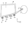
- FIG. 1 is a perspective view schematically showing an example of a visual line detection device according to the first embodiment.
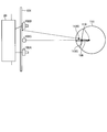
- FIG. 2 is a diagram schematically illustrating a positional relationship among the display device, the stereo camera device, the light source, and the eyeball of the subject according to the first embodiment.
- FIG. 3 is a diagram illustrating an example of a hardware configuration of the visual line detection device according to the first embodiment.
- FIG. 4 is a functional block diagram illustrating an example of a line-of-sight detection device according to the first embodiment.
- FIG. 5 is a schematic diagram for explaining the calculation method of the position data of the corneal curvature center according to the first embodiment.
- FIG. 6 is a schematic diagram for explaining the calculation method of the position data of the corneal curvature center according to the first embodiment.
- FIG. 7 is a flowchart illustrating an example of a gaze detection method according to the first embodiment.
- FIG. 8 is a diagram schematically illustrating a relationship among a pupil of a subject wearing glasses, a stereo camera device, and a light source.
- FIG. 9 is a schematic diagram illustrating a state in which at least a part of the reflected image of the light source in the glasses overlaps the pupil of the subject in the visual field region of the stereo camera device.
- FIG. 10 is a diagram schematically illustrating a relationship among a pupil of a subject wearing glasses, a stereo camera device, and a light source.
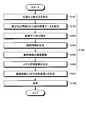
- FIG. 11 is a flowchart illustrating an example of the alignment support process according to the first embodiment.
- FIG. 11 is a flowchart illustrating an example of the alignment support process according to the first embodiment.
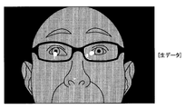
- FIG. 12 is a diagram schematically illustrating an example of image data acquired by the image data acquisition unit according to the first embodiment.
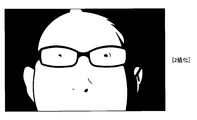
- FIG. 13 is a diagram schematically illustrating an example of binarized image data according to the first embodiment.
- FIG. 14 is a diagram schematically illustrating an example of a facial feature image of a subject according to the first embodiment.
- FIG. 15 is a diagram schematically illustrating an example of a feature part image with reduced luminance according to the first embodiment.
- FIG. 16 is a diagram schematically illustrating an example of a spectacle reflection image according to the first embodiment.
- FIG. 17 is a diagram schematically illustrating an example of a synthesized image obtained by synthesizing the feature part image and the glasses reflection image according to the first embodiment.
- FIG. 18 is a diagram illustrating an example of the display device according to the first embodiment.
- FIG. 19 is a schematic diagram for explaining an example of calibration processing according to the first embodiment.
- FIG. 20 is a flowchart illustrating an example of calibration processing according to the first embodiment.
- FIG. 21 is a schematic diagram for explaining an example of a line-of-sight detection process according to the first embodiment.
- FIG. 22 is a flowchart illustrating an example of a line-of-sight detection process according to the first embodiment.
- FIG. 23 is a timing chart illustrating operation timings of the first camera, the second camera, the first light source, and the second light source in the alignment support processing according to the second embodiment.
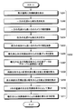
- FIG. 24 is a flowchart illustrating an example of the alignment support process according to the second embodiment.
- the direction parallel to the X axis of the predetermined surface is the X axis direction
- the direction parallel to the Y axis of the predetermined surface orthogonal to the X axis is the Y axis direction
- the predetermined plane includes an XY plane.
- FIG. 1 is a perspective view schematically showing an example of a visual line detection device 100 according to the present embodiment.
- the line-of-sight detection device 100 is used, for example, in a diagnosis support device that supports diagnosis of developmental disabilities.
- the line-of-sight detection device 100 includes a display device 101, a stereo camera device 102, and a light source 103.
- the display device 100 includes a flat panel display such as a liquid crystal display (LCD) or an organic EL display (OELD).
- a flat panel display such as a liquid crystal display (LCD) or an organic EL display (OELD).
- the display screen 101S of the display device 100 is substantially parallel to the XY plane.
- the X-axis direction is the left-right direction of the display screen 101S
- the Y-axis direction is the up-down direction of the display screen 101S
- the Z-axis direction is the depth direction orthogonal to the display screen 101S.
- the stereo camera device 102 captures the subject's image data by photographing the subject.
- the stereo camera device 102 includes a first camera 102A and a second camera 102B arranged at different positions.
- the stereo camera device 102 is disposed below the display screen 101S of the display device 101.
- the first camera 102A and the second camera 102B are arranged in the X-axis direction.
- the first camera 102A is arranged in the ⁇ X direction with respect to the second camera 102B.
- Each of the first camera 102A and the second camera 102B includes an infrared camera, and includes, for example, an optical system capable of transmitting near-infrared light having a wavelength of 850 [nm] and an imaging element capable of receiving near-infrared light.
- the light source 103 emits detection light.
- the light source 103 includes a first light source 103A and a second light source 103B arranged at different positions.
- the light source 103 is disposed below the display screen 101S of the display device 101.
- the first light source 103A and the second light source 103B are arranged in the X-axis direction.
- the first light source 103A is arranged in the ⁇ X direction with respect to the first camera 102A.
- the second light source 103B is arranged in the + X direction with respect to the second camera 102B.
- Each of the first light source 103A and the second light source 103B includes an LED (light emitting diode) light source, and can emit, for example, near-infrared light having a wavelength of 850 [nm]. Note that the first light source 103A and the second light source 103B may be disposed between the first camera 102A and the second camera 102B.
- LED light emitting diode
- FIG. 2 is a diagram schematically illustrating a positional relationship among the display device 101, the stereo camera device 102, the light source 103, and the eyeball 111 of the subject according to the present embodiment.
- the light source 103 emits infrared light that is detection light to illuminate the eyeball 111 of the subject.
- the stereo camera device 102 captures the eyeball 111 with the second camera 102B when the detection light emitted from the first light source 103A is applied to the eyeball 111, and the detection light emitted from the second light source 103B is applied to the eyeball 111.
- the eyeball 111 is photographed by the first camera 102A.
- a frame synchronization signal is output from at least one of the first camera 102A and the second camera 102B.
- the first light source 103A and the second light source 103B emit detection light based on the frame synchronization signal.
- the first camera 102A acquires image data of the eyeball 111 when the detection light emitted from the second light source 103B is irradiated to the eyeball 111.
- the second camera 102B acquires image data of the eyeball 111 when the detection light emitted from the first light source 103A is irradiated on the eyeball 111.
- the detection light When the detection light is irradiated to the eyeball 111, a part of the detection light is reflected by the pupil 112. The light reflected by the pupil 112 enters the stereo camera device 102.
- a cornea reflection image 113 is formed on the eyeball 111.
- the cornea reflection image 113 is a reflection image of the light source 103 on the cornea surface. The light from the cornea reflection image 113 enters the stereo camera device 102.
- the intensity of light incident on the stereo camera device 102 from the pupil 112 is reduced, and the cornea The intensity of light incident on the stereo camera device 102 from the reflected image 113 is increased. That is, the image of the pupil 112 acquired by the stereo camera device 102 has low brightness, and the image of the cornea reflection image 113 has high brightness.
- the stereo camera device 102 can detect the position of the pupil 112 and the position of the cornea reflection image 113 based on the luminance of the acquired image.
- FIG. 3 is a diagram illustrating an example of a hardware configuration of the visual line detection device 100 according to the present embodiment.
- the line-of-sight detection device 100 includes a display device 101, a stereo camera device 102, a light source 103, a computer system 20, an input / output interface device 30, a drive circuit 40, an output device 50, An input device 60 and an audio output device 70 are provided.
- the computer system 20 includes an arithmetic processing device 20A and a storage device 20B.
- a computer program 20C is stored in the storage device 20B.
- the computer system 20, the drive circuit 40, the output device 50, the input device 60, and the audio output device 70 perform data communication via the input / output interface device 30.
- the arithmetic processing unit 20A includes a microprocessor such as a CPU (central processing unit).
- the storage device 20B includes a nonvolatile memory such as a ROM (read only memory) or a volatile memory such as a RAM (random access memory).
- the arithmetic processing device 20A performs arithmetic processing according to the computer program 20C stored in the storage device 20B.
- the drive circuit 40 generates a drive signal and outputs it to the display device 101, the stereo camera device 102, and the light source 103. Further, the drive circuit 40 supplies the image data of the eyeball 111 acquired by the stereo camera device 102 to the computer system 20 via the input / output interface device 30.
- the output device 50 includes a display device such as a flat panel display.
- the output device 50 may include a printing device.
- the input device 60 generates input data when operated.
- the input device 60 includes a keyboard or mouse for a computer system.
- the input device 60 may include a touch sensor provided on the display screen of the output device 50 that is a display device.
- the audio output device 70 includes a speaker and outputs, for example, audio for prompting the subject to pay attention.
- the display device 101 and the computer system 20 are separate devices. Note that the display device 101 and the computer system 20 may be integrated.
- the line-of-sight detection device 100 includes a tablet personal computer
- the computer system 20, the input / output interface device 30, the drive circuit 40, and the display device 101 may be mounted on the tablet personal computer.
- FIG. 4 is a functional block diagram showing an example of the visual line detection device 100 according to the present embodiment.
- the input / output interface device 30 includes an input / output unit 302.
- the drive circuit 40 generates a drive signal for driving the display device 101 and outputs the drive signal to the display device 101, and generates a drive signal for driving the first camera 102A to generate the first camera.
- a first camera input / output unit 404A that outputs to the second camera 102B
- a second camera input / output unit 404B that generates a drive signal for driving the second camera 102B and outputs it to the second camera 102B, the first light source 103A and the second light source 103A.
- a light source drive unit 406 that generates a drive signal for driving the two light sources 103B and outputs the drive signals to the first light source 103A and the second light source 103B.
- the first camera input / output unit 404A supplies the image data of the eyeball 111 acquired by the first camera 102A to the computer system 20 via the input / output unit 302.
- the second camera input / output unit 404B supplies the image data of the eyeball 111 acquired by the second camera 102B to the computer system 20 via the input / output unit 302.
- the computer system 20 controls the line-of-sight detection device 100.
- the computer system 20 includes an image data acquisition unit 202, an input data acquisition unit 204, an image processing unit 206, a display control unit 208, a light source control unit 210, a camera control unit 211, a position detection unit 212, a curvature, and the like.
- a center calculation unit 214, a line-of-sight detection unit 216, a distance data acquisition unit 218, a storage unit 220, and an output control unit 222 are included.
- the functions of the computer system 20 are exhibited by the arithmetic processing unit 20A, the storage unit 20B, and the computer program 20C stored in the storage unit 20B.
- the image data acquisition unit 202 acquires the image data of the subject's face acquired by the stereo camera device 102 including the first camera 102A and the second camera 102B from the stereo camera device 102 via the input / output unit 302.
- the image data is digital data.
- the test subject's face image data includes image data of the eyeball 111.
- the stereo camera device 102 images the face of the subject to which the detection light emitted from the light source 103 is irradiated.
- the image data acquisition unit 202 acquires the image data of the face of the subject irradiated with the detection light emitted from the light source 103 from the stereo camera device 102 via the input / output unit 302.
- the input data acquisition unit 204 acquires input data generated by operating the input device 60 from the input device 60 via the input / output unit 302.
- the image processing unit 206 performs image processing on the image data acquired by the image data acquisition unit 202.
- the image processing unit 206 performs image processing on the image data, and generates a feature part image indicating an image of a characteristic part of the face of the subject and a spectacle reflection image indicating a reflection image of the light source 103 in the glasses attached to the face of the subject. To do.
- the display control unit 208 causes the display device 101 to display a specific image.
- the display control unit 208 causes the display device 101 to display a composite image obtained by combining the feature part image generated by the image processing unit 206 and the glasses reflection image.
- the display control unit 208 causes the display device 101 to display the feature part image and the glasses reflection image in different display forms in the composite image obtained by combining the feature part image and the glasses reflection image.
- the display form in the display device 101 includes at least one of the luminance, color, brightness, and saturation of the image.
- the display control unit 208 causes the display device 101 to display the spectacle reflection image more emphasized than the feature part image.
- the display control unit 208 causes the display device 101 to display the spectacle reflection image with higher brightness than the feature part image in the composite image.
- the display control unit 208 may cause the glasses reflection image to be displayed on the display device 101 with higher brightness than the feature image in the composite image, or may be displayed on the display device 101 with high saturation.
- the light source control unit 210 controls the operation state of the first light source 103A and the second light source 103B by controlling the light source driving unit 406.
- the light source controller 210 controls the first light source 103A and the second light source 103B so that the first light source 103A and the second light source 103B emit detection light at different timings. Further, the light source control unit 210 controls the amount of detection light emitted from the first light source 103A and the amount of detection light emitted from the second light source 103B.
- Control of the amount of detection light emitted from the first light source 103A includes at least one of control of the light emission intensity of the first light source 103A and control of the light emission time of the first light source 103A.
- the control of the amount of detection light emitted from the second light source 103B includes at least one of control of the light emission intensity of the second light source 103B and control of the light emission time of the second light source 103B.
- the light source control unit 210 includes the first light source 103A and the first light source 103A so that the amount of detection light emitted from the first light source 103A is equal to the amount of detection light emitted from the second light source 103B.
- the second light source 103B is controlled.
- the camera control unit 211 controls the operating state of the stereo camera device 102 including the first camera 102A and the second camera 102B by controlling the first camera input / output unit 404A and the second camera input / output unit 404B.
- the camera control unit 211 controls the exposure value of the detection light in the first camera 102A and the exposure value of the detection light in the second camera 102B.
- the exposure value of the detection light in the first and second cameras 102A and 102B refers to the imaging element from the face of the subject illuminated with the detection light via the optical system of the first and second cameras 102A and 102B. The exposure amount of incident detection light.
- the control of the exposure value of the detection light in the first and second cameras 102A and 102B includes the control of the shutter speed of the first and second cameras 102A and 102B and the aperture value of the optical system of the first and second cameras 102A and 102B. Including at least one of the controls.
- the position detection unit 212 detects the position data of the pupil center based on the image data of the eyeball 111 acquired by the image data acquisition unit 202. Further, the position detection unit 212 detects position data of the corneal reflection center based on the image data of the eyeball 111 acquired by the image data acquisition unit 202.
- the pupil center is the center of the pupil 112.
- the cornea reflection center is the center of the cornea reflection image 113.
- the position detection unit 212 detects the position data of the pupil center and the position data of the corneal reflection center for the left and right eyeballs 111 of the subject.
- the curvature center calculation unit 214 calculates position data of the corneal curvature center of the eyeball 111 based on the image data of the eyeball 111 acquired by the image data acquisition unit 202.
- the line-of-sight detection unit 216 detects the line of sight of the subject based on the image data of the eyeball 111 acquired by the image data acquisition unit 202.
- the subject's line of sight includes a line-of-sight vector indicating the line-of-sight direction that the subject is looking at.
- the line-of-sight detection unit 216 detects the line-of-sight vectors of the left and right eyeballs 111 of the subject based on the pupil center position data and the corneal curvature center position data acquired from the image data of the eyeball 111.
- the line-of-sight detection unit 216 detects position data of the gaze point of the subject based on the detected line-of-sight vector.
- the subject's gaze point includes an intersection between the subject's line-of-sight vector and the display screen 101 ⁇ / b> S of the display device 101.
- the position data of the gazing point refers to the position data of the intersection point between the subject's line-of-sight vector defined in the global coordinate system and the display screen 101S of the display device 101.
- the distance data acquisition unit 218 acquires distance data between the display screen 101S of the display device 101 and the face of the subject.
- the distance data acquisition unit 218 detects distance data based on the position data of the pupil center detected by the position detection unit 212. By detecting the position data of the pupil center in the global coordinate system, the distance between the center of the display screen 101S of the display device 101 and the eyeball 111 of the subject is calculated.
- the distance data acquisition unit 218 acquires the distance between the center of the display screen 101S of the display device 101 and the eyeball 111 of the subject as distance data between the display screen 101S of the display device 101 and the face of the subject.
- the storage unit 220 stores the computer program 20C and various data.
- the output control unit 222 outputs data to at least one of the display device 101, the output device 50, and the audio output device 70.
- the output control unit 222 causes the display device 101 or the output device 50 to display position data of the gazing point of the left and right eyeballs 111 of the subject.
- the curvature center calculation unit 214 calculates position data of the corneal curvature center of the eyeball 111 based on the image data of the eyeball 111.
- FIG. 5 and 6 are schematic diagrams for explaining a method for calculating the position data of the corneal curvature center 110 according to the present embodiment.
- FIG. 5 shows an example in which the eyeball 111 is illuminated by one light source 103C.
- FIG. 6 shows an example in which the eyeball 111 is illuminated by the first light source 103A and the second light source 103B.
- the light source 103C is disposed between the first camera 102A and the second camera 102B.
- Pupil center 112 ⁇ / b> C is the center of pupil 112.
- the cornea reflection center 113 ⁇ / b> C is the center of the cornea reflection image 113.
- the pupil center 112C indicates the pupil center when the eyeball 111 is illuminated by one light source 103C.
- the corneal reflection center 113C indicates the corneal reflection center when the eyeball 111 is illuminated by one light source 103C.
- the corneal reflection center 113C exists on a straight line connecting the light source 103C and the corneal curvature center 110.
- the corneal reflection center 113C is positioned at the midpoint between the corneal surface and the corneal curvature center 110.
- the corneal curvature radius 109 is the distance between the corneal surface and the corneal curvature center 110.
- the position data of the corneal reflection center 113C is detected by the stereo camera device 102.
- the corneal curvature center 110 exists on a straight line connecting the light source 103C and the corneal reflection center 113C.
- the curvature center calculator 214 calculates position data on the straight line at which the distance from the corneal reflection center 113C is a predetermined value as position data of the corneal curvature center 110.
- the predetermined value is a value determined in advance based on a general radius of curvature of the cornea and the like, and is stored in the storage unit 220.
- the first camera 102A and the second light source 103B, and the second camera 102B and the first light source 103A are symmetrical with respect to a straight line passing through an intermediate position between the first camera 102A and the second camera 102B. It is arranged at the position. It can be considered that the virtual light source 103V exists at an intermediate position between the first camera 102A and the second camera 102B.
- the corneal reflection center 121 indicates the corneal reflection center in an image obtained by photographing the eyeball 111 with the second camera 102B.
- a corneal reflection center 122 indicates a corneal reflection center in an image obtained by photographing the eyeball 111 with the first camera 102A.
- a corneal reflection center 124 indicates a corneal reflection center corresponding to the virtual light source 103V.
- the position data of the cornea reflection center 124 is calculated based on the position data of the cornea reflection center 121 and the position data of the cornea reflection center 122 acquired by the stereo camera device 102.
- the stereo camera device 102 detects position data of the corneal reflection center 121 and position data of the corneal reflection center 122 in the local coordinate system defined by the stereo camera device 102.
- camera calibration is performed in advance by the stereo calibration method, and conversion parameters for converting the three-dimensional local coordinate system of the stereo camera device 102 into a three-dimensional global coordinate system are calculated.
- the conversion parameters are stored in the storage unit 220.
- the curvature center calculation unit 214 converts the position data of the corneal reflection center 121 and the position data of the corneal reflection center 122 acquired by the stereo camera device 102 into position data in the global coordinate system using the conversion parameters.
- the curvature center calculation unit 214 calculates position data of the corneal reflection center 124 in the global coordinate system based on the position data of the corneal reflection center 121 and the position data of the corneal reflection center 122 defined in the global coordinate system.
- the corneal curvature center 110 exists on a straight line 123 connecting the virtual light source 103V and the corneal reflection center 124.
- the curvature center calculation unit 214 calculates position data on the straight line 123 where the distance from the corneal reflection center 124 is a predetermined value as position data of the corneal curvature center 110.
- the predetermined value is a value determined in advance based on a general radius of curvature of the cornea and the like, and is stored in the storage unit 220.
- the corneal curvature center 110 is calculated by the same method as the method when there is one light source.
- the corneal curvature radius 109 is the distance between the corneal surface and the corneal curvature center 110. Accordingly, the corneal curvature radius 109 is calculated by calculating the position data of the corneal surface and the position data of the corneal curvature center 110.
- position data of the corneal curvature center 110, position data of the corneal reflection center 124, and position data of the pupil center 112C in the global coordinate system are calculated.
- the gaze detection unit 216 can detect the gaze vector of the subject based on the position data of the pupil center 112C and the position data of the corneal curvature center 110.
- the distance data acquisition unit 218 can acquire distance data between the display screen of the display device 101 and the subject's face including the eyeball 111 based on the position data of the pupil center 112C.
- FIG. 7 is a flowchart illustrating an example of a gaze detection method according to the present embodiment.
- alignment support processing for adjusting the visual axis detection device 100 and the subject to an appropriate relative position
- a calibration process including a distance data calculation process and a line-of-sight detection process (step S300) are performed.
- the alignment support process will be described.
- the detection light emitted from the light source 103 and applied to the face of the subject may be reflected by the lens of the glasses.
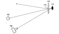
- FIG. 8 is a diagram schematically showing the relationship among the pupil 112 of the subject wearing the glasses 170, the stereo camera device 102, and the light source 103.
- FIG. 8 shows a state in which the position of the reflected image 172 of the light source 103 in the glasses 170 and the position of the pupil 112 of the subject match in the visual field region of the stereo camera device 102.
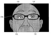
- FIG. 9 is a schematic diagram showing a state in which at least a part of the reflected image 172 of the light source 103 in the glasses 170 overlaps the pupil 112 of the subject in the visual field region of the stereo camera device 102.
- the stereo camera device 102 when the reflected image 172 of the light source 103 is formed in the lens of the glasses 170 and the reflected image 172 and the pupil 112 of the subject overlap in the visual field region of the stereo camera device 102, the stereo camera device 102. It becomes difficult to acquire the image data of the pupil 112 and the corneal reflection image 113 of the subject satisfactorily. When the pupil 112 and the cornea reflection image 113 are not detected well, the detection accuracy of the subject's line of sight decreases.
- FIG. 10 is a schematic diagram showing a state in which the position of the reflected image 172 of the light source 103 in the glasses 170 and the position of the pupil 112 of the subject do not match in the visual field region of the stereo camera device 102.
- the stereo camera device 102 does not overlap the reflected image 172 and the pupil 112 of the subject in the visual field region of the stereo camera device 102.
- the pupil 112 and the cornea reflection image 113 are detected satisfactorily, a decrease in the detection accuracy of the subject's line of sight is suppressed.
- the line-of-sight detection device 100 compares the subject wearing the glasses 170 with the stereo camera device 102 and the light source 103 before the calibration process (step S200) and the line-of-sight detection process (step S300) are started.
- the subject or the measurer is supported so that the position is in the state shown in FIG. That is, the line-of-sight detection apparatus 100 prevents the reflected image 172 and the subject's eyes from overlapping in the visual field region of the stereo camera apparatus 102 before the calibration process (step S200) and the line-of-sight detection process (step S300) are started.
- a process for prompting the subject or the measurer to adjust at least one of the position of the subject's face, the orientation of the face, the position of the glasses 170 and the orientation of the glasses 170 is performed.
- FIG. 11 is a flowchart showing an example of the alignment support process according to the present embodiment.
- the alignment support process (step S ⁇ b> 100) includes a step of emitting detection light from the light source 103 and irradiating the subject's face (step S ⁇ b> 101), and a detection light emitted from the light source 103.
- a step of acquiring image data of the face of the subject (step S102), a step of binarizing the acquired image data (step S103), and a feature indicating an image of a facial feature portion from the binarized image data
- a step of generating a partial image (step S104), a step of adjusting the luminance of the generated characteristic portion image (step S105), and a spectacle reflection indicating a reflection image 172 of the light source 103 in the spectacles 170 worn on the face of the subject.
- a step of generating an image (step S106), a step of synthesizing the feature portion image and the spectacle reflection image (step S107), a feature portion image and the mecha Ne and a reflection image and a step of displaying the synthesized image synthesized in the display device 101 (step S108).
- Detection light is emitted from the light source 103 (step S101).
- Image data of the face of the subject irradiated with the detection light is acquired by the stereo camera device 102.
- Image data of the face of the subject is acquired by at least one of the first camera 102A and the second camera 102B.
- the image data of the subject's face is acquired by the first camera 102A.
- the image data of the subject's face may be acquired by the second camera 102B. Note that both the image data acquired by the first camera 102A and the image data acquired by the second camera 102B may be used.
- the image data acquisition unit 202 acquires image data of the face of the subject irradiated with the detection light from the stereo camera device 102 (step S102).
- FIG. 12 is a diagram schematically illustrating an example of image data acquired by the image data acquisition unit 202 according to the present embodiment.
- FIG. 12 shows raw data, which is image data before image processing is performed, taken by the stereo camera device 102 when infrared light, which is detection light, is irradiated on the face of the subject. .
- the image processing unit 206 performs image processing on the image data acquired by the image data acquisition unit 202.
- the image processing unit 206 binarizes the image data acquired by the image data acquisition unit 202 (step S103).
- FIG. 13 is a diagram schematically illustrating an example of binarized image data according to the present embodiment.
- the binarization of image data refers to a process of converting image data composed of a plurality of pixels into two gradations of white and black based on a prescribed threshold value.
- binarization is performed based on the defined first threshold value.
- the image processing unit 206 performs processing to replace the pixel with white when the luminance of the pixel is equal to or higher than the first threshold, and to replace the pixel with black when the luminance of the pixel is lower than the first threshold.
- the first threshold value in binarization may be a predetermined fixed value, may be an intermediate value between the highest value and the lowest value among the luminances of a plurality of pixels of the acquired image data, An intermediate value may be used.
- the binarization is a p-tile method that determines the first threshold value according to the ratio of white pixels in the binarized result image.
- the bottom value of the valley of the histogram is the first. It is implemented based on at least one of a mode method for setting a threshold value and a discriminant analysis method for determining a first threshold value so that the inter-class variance is maximized when the image luminance histogram is divided into two classes at a certain threshold value. May be.
- the image processing unit 206 generates a feature portion image indicating an image of the facial feature portion from the binarized image data (step S104).
- the feature image includes a contour image on the face of the subject.
- FIG. 14 is a diagram schematically illustrating an example of the face contour image 174M of the subject according to the present embodiment.
- the contour image 174M includes an edge image indicating the boundary between the white portion and the black portion of the binarized image data.
- the brightness of the contour image 174M generated in step S104 is equal to or higher than the first threshold value.
- the image processing unit 206 performs edge detection of the binarized image data.
- Edge detection of image data refers to processing for detecting a boundary where the luminance of a pixel changes abruptly in image data composed of a plurality of pixels.
- the image processing unit 206 may perform differential processing on the luminance of adjacent pixels to detect edges, or may detect edges by template matching.
- a contour image 174M on the face of the subject as shown in FIG. 14 is generated.
- the contour image 174M on the face is attached to the contour image of the subject's face, the contour image of the subject's eyelid, the contour image of the subject's pupil, the contour image of the subject's nostril, the contour image of the subject's mouth, and the face of the subject. At least one of the contour images of the glasses 170.
- the contour image 174M may be an image that can recognize or estimate the position of the pupil 112 from the contour image 174M when the subject or the measurer views the contour image 174M.
- the image processing unit 206 adjusts the luminance of the generated contour image 174M (step S105).
- the image processing unit 206 reduces the brightness of the contour image 174M generated in step S104.
- the brightness of the contour image 174M generated in step S105 is lower than the first threshold value.
- FIG. 15 is a diagram schematically illustrating an example of a contour image 174M with reduced luminance according to the present embodiment.
- FIG. 15 shows an example in which the brightness of the contour image 174M is reduced to 50 [%].
- the image processing unit 206 generates a spectacle reflection image indicating the reflection image 172 of the light source 103 in the spectacles 170 worn on the face of the subject (step S106).
- FIG. 16 is a diagram schematically illustrating an example of the spectacle reflection image 172M according to the present embodiment.
- the image processing unit 206 binarizes the image data (see FIG. 12) acquired in step S102, and generates a glasses reflection image 172M.
- a second threshold value higher than the first threshold value specified in step S103 is specified.
- the image processing unit 206 binarizes the image data acquired by the image data acquisition unit 202 based on a second threshold value that is higher than the first threshold value.
- the image processing unit 206 performs a process of replacing the pixel with white when the luminance of the pixel is equal to or higher than the second threshold, and replacing the pixel with black when the luminance of the pixel is lower than the second threshold. To do.
- a glasses reflected image 172M as shown in FIG. 16 is generated.
- FIG. 17 is a diagram schematically illustrating an example of a combined image 176M obtained by combining the contour image 174M and the glasses reflection image 172M according to the present embodiment. As shown in FIG. 17, in the synthesized image 176M, the luminance of the glasses reflection image 172M is higher than the luminance of the contour image 174M.
- the contour image 174M includes pixels indicating a contour and pixels indicating a background other than the contour.
- the spectacle reflection image 172M includes a pixel indicating the reflection image 172 and a pixel indicating the background other than the reflection image 172.
- the pixels of the contour image 174M and the pixels of the glasses reflection image 172M corresponding to the pixels of the contour image 174M are synthesized.
- the brightness of the pixel of the contour image 174M is multivalued, and the pixel indicating the contour in the contour image 174M can be regarded as gray.
- the pixel indicating the reflection image 172 can be regarded as white.
- Pixels indicating a background other than the contour in the contour image 174M and pixels indicating a background other than the reflected image 172 in the spectacle reflection image 172M can be regarded as black.
- any two of the white pixel, the gray pixel, and the black pixel are synthesized Pixels with high brightness are selected as pixels of the composite image 176M.
- the pixel of the combined image 176M of the outline image 174M and the glasses reflection image 172M is It is gray.
- the composite image 176M of the contour image 174M and the spectacle reflection image 172M The pixel is white.
- the display control unit 208 causes the display device 101 to display a composite image 176M in which the contour image 174M and the glasses reflection image 172M are combined (step S108).
- the glasses reflection image 172M has higher brightness than the contour image 174M.
- the spectacle reflection image 172M has a high luminance equal to or higher than the second threshold, and the contour image 174M has a luminance lower than the first threshold.
- the luminance of the glasses reflection image 172M is 100 [%]
- the luminance of the contour image 174M is 50 [%]. Therefore, the glasses reflection image 172M is displayed on the display device 101 with more emphasis than the contour image 174M.
- FIG. 18 is a diagram illustrating an example of the display device 101 according to the present embodiment.
- the display control unit 208 displays, on the display screen 101S of the display device 101, a first display area 101A that displays a composite image 176M of a glasses reflection image 172M and a contour image 174M, and a first display that displays an animation. 2 display areas 101B are formed.
- the display control unit 208 causes the display device 101 to display the glasses reflection image 172M with higher brightness than the contour image 174M.
- the display control unit 208 causes the glasses reflection image 172M to be displayed on the display device 101 with a high luminance equal to or higher than the second threshold, and causes the display device 101 to display the contour image 174M with a luminance lower than the first threshold.
- the display control unit 208 causes the display device 101 to display the contour image 174M and the glasses reflection image 172M in different colors. In the present embodiment, the display control unit 208 displays the contour image 174M in orange and the glasses reflection image 172M in yellow. Note that the display control unit 208 may cause the display device 101 to display the contour image 174M and the glasses reflection image 172M with different brightness or saturation. For example, the glasses reflection image 172M may be displayed on the display device 101 with higher brightness or higher saturation than the contour image 174M.
- the computer system 20 performs image processing on the subject's face image data acquired by the stereo camera device 102 in real time, and displays it in the first display area 101A of the display device 101. That is, the moving image of the composite image 176M is displayed on the display device 101.
- the subject or the measurer can see the reflection image 172 of the light source 103 and the subject in the field of view of the stereo camera device 102 while viewing the composite image 176M displayed on the display device 101.
- the position or orientation of the subject's face can be adjusted, or the position or orientation of the glasses 170 can be adjusted so that the eye does not overlap.
- the subject or the measurer can adjust the position or orientation of the subject's face or the glasses 170 without feeling uncomfortable or disgusting. Can be adjusted.
- the display control unit 208 causes the display screen 101S to display the guide line 180 whose size and position are fixed on the display screen 101S of the display device 101.
- the guide line 180 forms a quadrangle.
- the guide line 180 is displayed so as to overlap the synthesized image 176M in the first display area 101A.
- the subject or the measurer can adjust the position of the subject's face so that the subject's eyes are placed inside the square guide line 180 while viewing the composite image 176M.
- an animation is displayed during an infant medical examination.
- the line of sight of the infant is detected while the infant is sitting on a guardian's lap sitting on a chair.
- the relative position between the line-of-sight detection device 100 and the infant's face is adjusted by the guardian adjusting the position or orientation of the infant's face, or by the measurer adjusting the position or orientation of the line-of-sight detection device 100.
- an animation that attracts the attention of the infant is displayed in the second display area 101B in order to cause the display device 100 to gaze at the infant.
- the display data displayed in the second display area 102B may be a moving image or a still image. Any display data that can attract the attention of an infant may be used.
- distance data between the display screen 101S of the display device 101 and the eye or face of the subject is acquired by the distance data acquisition unit 218.
- the distance data acquisition unit 218 detects the pupil 112 based on the image data of the eyeball 111 of the subject acquired by the stereo camera device 102, and calculates the position of the pupil center 112C in the global coordinate system.
- the distance data acquisition unit 218 can calculate the distance between the center of the display screen 101S of the display device 101 and the eye of the subject by calculating the position of the pupil center 112C in the global coordinate system.
- the display control unit 208 causes the display device 101 to display the distance data acquired by the distance data acquisition unit 218.
- image data of the scale 190 indicating the distance between the display screen 101S of the display device 101 and the eye of the subject is displayed on the display device 101.
- character data of “small”, “good”, and “tooi” are displayed on the display device 101.
- the display control unit 208 moves the indicator 192 along the scale 190 based on the distance data acquired by the distance data acquisition unit 218.
- the display control unit 208 moves the indicator 192 to “good”.
- the display control unit 208 moves the indicator 192 to “small”.
- the display control unit 208 moves the indicator 192 to “Tooi”.
- the face of the subject is placed at the focal position of the optical system of the stereo camera device 102.
- An appropriate value for the distance between the display screen 101S of the display device 101 and the subject's eye is the distance at which the subject's eye or face is placed at the focal position of the optical system of the stereo camera device 102. While looking at the indicator 192, the subject or the measurer can adjust the position of the subject's face so that the indicator 192 is “good”.
- the alignment support process is performed.
- the calibration includes the calculation process of the position data of the corneal curvature center 110 and the calculation process of the distance data between the pupil center 112C and the corneal curvature center 110. Is executed (step S200).
- FIG. 19 is a schematic diagram for explaining an example of calibration processing according to the present embodiment.
- the calibration process includes calculating position data of the corneal curvature center 110 and calculating a distance 126 between the pupil center 112C and the corneal curvature center 110.
- the target position 130 for making the subject gaze is set.
- the target position 130 is defined in the global coordinate system.
- the target position 130 is set to the center position of the display screen 101S of the display device 101, for example.
- the target position 130 may be set to the end position of the display screen 101S.
- the display control unit 208 displays the target image at the set target position 130. This makes it easier for the subject to gaze at the target position 130.
- the straight line 131 is a straight line connecting the virtual light source 103V and the corneal reflection center 113C.
- a straight line 132 is a straight line connecting the target position 130 and the pupil center 112C.
- the corneal curvature center 110 is an intersection of the straight line 131 and the straight line 132.
- the curvature center calculation unit 214 is based on the position data of the virtual light source 103V, the position data of the target position 130, the position data of the pupil center 112C, and the position data of the corneal reflection center 113C, and the position data of the corneal curvature center 110. Can be calculated.
- FIG. 20 is a flowchart showing an example of the calibration process (step S200) according to the present embodiment.
- the output control unit 222 displays the target image on the display screen 101S of the display device 101 (step S201).
- the subject can watch the target position 130 by watching the target image.
- the light source control unit 210 controls the light source driving unit 406 to emit detection light from one of the first light source 103A and the second light source 103B (step S202).
- the stereo camera device 102 photographs the eye of the subject with the camera having the longer distance from the light source that emitted the detection light among the first camera 102A and the second camera 102B (step S203).
- the light source control unit 210 controls the light source driving unit 406 to emit detection light from the other light source of the first light source 103A and the second light source 103B (step S204).
- the stereo camera device 102 photographs the eye of the subject with the camera having the longer distance from the light source that emitted the detection light among the first camera 102A and the second camera 102B (step S205).
- the pupil 112 is detected by the stereo camera device 102 as a dark portion, and the cornea reflection image 113 is detected by the stereo camera device 102 as a bright portion. That is, the image of the pupil 112 acquired by the stereo camera device 102 has low brightness, and the image of the cornea reflection image 113 has high brightness.
- the position detection unit 212 can detect the position data of the pupil 112 and the position data of the cornea reflection image 113 based on the luminance of the acquired image. Further, the position detection unit 212 calculates position data of the pupil center 112 ⁇ / b> C based on the image data of the pupil 112. Further, the position detection unit 212 calculates position data of the corneal reflection center 113C based on the image data of the corneal reflection image 113 (step S206).
- the position data detected by the stereo camera device 102 is position data defined by the local coordinate system.
- the position detection unit 212 uses the conversion parameters stored in the storage unit 220 to perform coordinate conversion of the position data of the pupil center 112C and the position data of the corneal reflection center 113C detected by the stereo camera device 102, and perform global conversion.
- the position data of the pupil center 112C and the position data of the corneal reflection center 113C defined by the coordinate system are calculated (step S207).
- the curvature center calculation unit 214 obtains a straight line 131 connecting the corneal reflection center 113C defined by the global coordinate system and the virtual light source 103V (step S208).
- the curvature center calculation unit 214 calculates a straight line 132 connecting the target position 130 defined on the display screen 101S of the display device 101 and the pupil center 112C (step S209).
- the curvature center calculation unit 214 obtains an intersection between the straight line 131 calculated in step S208 and the straight line 132 calculated in step S209, and sets the intersection as the corneal curvature center 110 (step S210).
- the curvature center calculation unit 214 calculates the distance 126 between the pupil center 112C and the corneal curvature center 110, and stores it in the storage unit 220 (step S211). The stored distance is used to calculate the corneal curvature center 110 in the line-of-sight detection in step S300.
- the line-of-sight detection process is performed after the calibration process.
- the gaze detection unit 216 calculates the gaze vector of the subject and the position data of the gazing point based on the image data of the eyeball 111.
- FIG. 21 is a schematic diagram for explaining an example of a line-of-sight detection process according to the present embodiment.
- the line-of-sight detection process uses the distance 126 between the pupil center 112C and the corneal curvature center 110 obtained in the calibration process (step S200) to correct the position of the corneal curvature center 110 and the corrected corneal curvature center 110. Calculation of the gazing point using the position data.
- a gazing point 165 indicates a gazing point obtained from the corneal curvature center calculated using a general curvature radius value.
- the gazing point 166 indicates a gazing point obtained from the corneal curvature center calculated using the distance 126 obtained in the calibration process.
- the pupil center 112C indicates the pupil center calculated in the calibration process
- the corneal reflection center 113C indicates the corneal reflection center calculated in the calibration process.
- the straight line 173 is a straight line connecting the virtual light source 103V and the corneal reflection center 113C.
- the corneal curvature center 110 is the position of the corneal curvature center calculated from a general curvature radius value.
- the distance 126 is the distance between the pupil center 112C and the corneal curvature center 110 calculated by the calibration process.
- the corneal curvature center 110H indicates the position of the corrected corneal curvature center obtained by correcting the corneal curvature center 110 using the distance 126.
- the corneal curvature center 110H is obtained because the corneal curvature center 110 exists on the straight line 173 and the distance between the pupil center 112C and the corneal curvature center 110 is the distance 126.
- the line of sight 177 calculated when a general radius of curvature value is used is corrected to the line of sight 178.
- the gazing point on the display screen 101S of the display device 101 is corrected from the gazing point 165 to the gazing point 166.
- FIG. 22 is a flowchart showing an example of a line-of-sight detection process (step S300) according to the present embodiment. Note that the processing from step S301 to step S307 shown in FIG. 22 is the same as the processing from step S202 to step S208 shown in FIG.
- the curvature center calculation unit 214 calculates the position on the straight line 173 calculated in step S307 and the distance from the pupil center 112C equal to the distance 126 obtained by the calibration process as the corneal curvature center 110H (step S308).
- the line-of-sight detection unit 216 obtains a line-of-sight vector connecting the pupil center 112C and the corneal curvature center 110H (step S309).
- the line-of-sight vector indicates the line-of-sight direction that the subject is looking at.
- the line-of-sight detection unit 216 calculates position data of an intersection point between the line-of-sight vector and the display screen 101S of the display device 101 (step S310).
- the position data of the intersection of the line-of-sight vector and the display screen 101S of the display device 101 is the position data of the subject's point of interest on the display screen 101S defined by the global coordinate system.
- the line-of-sight detection unit 216 converts the position data of the gazing point defined in the global coordinate system into the position data on the display screen 101S of the display device 101 defined in the two-dimensional coordinate system (step S311). Thereby, the position data of the gazing point on the display screen 101S of the display device 101 that the subject looks at is calculated.
- the image processing unit 206 performs image processing on the image data of the face of the subject acquired by the image data acquisition unit 202 in the alignment support processing (step S100).
- the image processing unit 206 extracts a face outline image (feature part image) 174M and a glasses reflection image 172M from the acquired image data, and generates a composite image 176M.
- the composite image 176M generated by the image processing unit 206 is displayed on the display device 101. Therefore, the subject or the measurer looks at the synthesized image 176M displayed on the display device 101, so that the reflected image 172 of the light source 103 and the subject's eyes do not overlap in the visual field region of the stereo camera device 102.
- step S300 the line-of-sight detection process (step S300) performed after the alignment support process (step S100)
- the reflected image 172 of the light source 103 and the eye of the subject do not overlap in the visual field region of the stereo camera device 102.
- Eye gaze detection is performed. Thereby, the pupil 112 and the corneal reflection image 113 are detected satisfactorily while the influence of the reflection image 172 is sufficiently suppressed. Therefore, a decrease in the detection accuracy of the line of sight of the subject wearing the glasses 170 is suppressed.
- the raw data as shown in FIG. 12 is not displayed on the display device 101, but the composite image 176M as shown in FIGS. 17 and 18 is displayed on the display device 101.
- the detection light irradiated to the subject is infrared light.
- the raw data of the subject's face when irradiated with infrared light is more likely to give the subject or measurer a sense of discomfort or discomfort than the raw data of the subject's face when irradiated with visible light .
- the pupil appears white
- the blood vessel appears to be raised
- the eyelids appear too black
- the subject feels uncomfortable Or, there is a high possibility of aversion.
- raw data of the subject's face is subjected to image processing to generate a composite image 176M, and the generated composite image 176M is displayed on the display device 101. Therefore, the subject or the measurer adjusts the position or orientation of the subject's face or the position or orientation of the glasses 170 while looking at the composite image 176M displayed on the display device 101 without feeling uncomfortable or disgusting. Can be adjusted.
- the gaze detection device 100 when used in the infant medical examination, it is possible to suppress discomfort or disgust not only to the subject and the measurer but also to the guardian.
- the spectacle reflection image 172M is generated from the raw data by image processing including binarization.
- the glasses reflection image 172M By generating the glasses reflection image 172M, the reflection state of the infrared light in the glasses 170 is clearly grasped. Therefore, the subject or the measurer adjusts the position or orientation of the subject's face so that the reflected image 172 of the light source 103 and the subject's eyes do not overlap in the visual field region of the stereo camera device 102, or the subject wears the subject.
- the position or orientation of the glasses 170 can be adjusted.
- the contour image 174M is generated from the raw data by image processing including binarization and edge detection.
- the contour image 174M includes the contour image of the subject's face, the contour image of the subject's eyelid, the contour image of the subject's pupil 112, the contour image of the subject's nostril, the contour image of the subject's mouth, and the subject. At least one of contour images of the glasses 170 attached to the face of the person.
- These contour images 174M are images with which the subject's eye position can be recognized or estimated when the subject or the measurer looks at the contour image 174M.
- the subject or the measurer can recognize or estimate the approximate position of the subject's eyes based on the face contour image.
- the subject or the measurer can check the subject based on the contour image of the nostril or the contour image of the glasses 170.
- the approximate position of the eye can be recognized or inferred.
- the subject or the measurer can recognize the position of the eye of the subject.
- the contour image 174M that can recognize or estimate the position of the eye of the subject is displayed on the display device 101, so that the subject or the measurer can select the eye based on the contour image 174M and the spectacle reflection image 172M displayed on the display device 101.
- the position or orientation of the subject's face is adjusted so that the reflected image 172 of the light source 103 and the subject's eyes do not overlap in the visual field region of the stereo camera device 102. Or the position or orientation of the glasses 170 worn by the subject can be adjusted.
- the display control unit 208 causes the display device 101 to display the contour image 174M and the glasses reflection image 172M in the composite image 176M in different display forms.
- the display form includes at least one of luminance, color, brightness, and saturation.
- the display control unit 208 causes the display device 101 to display the glasses reflection image 172M with higher brightness than the contour image 174M. Accordingly, the subject or the measurer can quickly recognize the glasses reflection image 172M.
- a first threshold value for luminance and a second threshold value higher than the first threshold value are defined, and the image processing unit 206 generates a spectacle reflection image 172M having a luminance value equal to or higher than the second threshold value.
- a contour image 174M having a luminance lower than one threshold is generated.
- the display control unit 208 causes the glasses reflection image 172M to be displayed on the display device 101 with a high luminance equal to or higher than the second threshold, and causes the contour image 174M to be displayed on the display device 101 with a luminance lower than the first threshold.
- the luminance of the glasses reflection image 172M is set to 100 [%]
- the luminance of the contour image 174M is adjusted to 50 [%].
- the subject or the measurer can sufficiently distinguish the contour image 174M and the glasses reflection image 172M. Accordingly, the subject or the measurer smoothly adjusts the reflected image 172 of the light source 103 and the subject's eyes so as not to coincide with each other in the visual field region of the stereo camera device 102 while viewing the composite image 176M displayed on the display device 101. Can be implemented.
- distance data between the display screen 101S of the display device 101 and the face of the subject is displayed on the display device 101.
- a scale 190 and an indicator 192 are displayed on the display device 101 as distance data.
- the distance data displayed on the display device 101 assists the subject or the measurer so that the subject's face is arranged at the optimum position in the Z-axis direction in the line-of-sight detection process. Therefore, the subject or the measurer can place the face of the subject at an optimal distance with respect to the display device 101 and the stereo camera device 102 while looking at the indicator 192 of the display device 101.
- the focal position of the optical system of the stereo camera device 102 is fixed, if the distance between the subject and the display device 101 and the stereo camera device 102 is too short, the pupil 112 and the corneal reflection image 113 are accurately detected in the line-of-sight detection process. It becomes difficult to detect well. If the distance between the subject and the display device 101 and the stereo camera device 102 is too long, the eye image of the subject acquired by the stereo camera device 102 becomes small, and the pupil 112 and the cornea reflection image 113 are obtained in the line-of-sight detection process. Is difficult to detect with high accuracy.
- the subject or the measurer can place the face of the subject at an optimal position in the Z-axis direction while viewing the distance data displayed on the display device 101.
- the display control unit 208 causes the display screen 101S to display the guide line 180 whose size and position are fixed on the display screen 101S of the display device 101.
- the guide line 180 displayed on the display device 101 assists the subject so that the subject's face is arranged at an optimal position in the X-axis direction and the Y-axis direction in the line-of-sight detection process.
- the subject or the measurer can place the face of the subject at the optimal position in the line-of-sight detection process based on the guide line 180.
- the first threshold value and the second threshold value higher than the first threshold value are defined, the luminance of the glasses reflection image 172M is equal to or higher than the second threshold value, and the luminance of the contour image 174M is higher than the first threshold value. It was decided to be low.
- One threshold may be defined for the brightness, the brightness of the glasses reflection image 172M may be equal to or greater than the threshold, and the brightness of the contour image 174M may be less than the threshold.
- detection light is emitted from the light source 103 with a constant light amount, the first threshold value for brightness and the second threshold value higher than the first threshold value are defined, and the first threshold value is exceeded.
- the contour image 174M having a low luminance and the glasses reflection image 172M having a luminance higher than the second threshold are generated by image processing.
- the light amount of the detection light emitted from the light source 103 is adjusted, and based on the image data acquired by the stereo camera device 102 when the detection light whose light amount has been adjusted is irradiated on the subject's face.
- An example in which the contour image 174M and the glasses reflection image 172M are generated will be described.
- the image processing unit 208 includes the image data of the subject's face acquired by the stereo camera device 102 when the first light amount detection light is emitted from the light source 103 and the light amount from the light source 103.
- the contour image 174M and the spectacle reflection image 172M are generated based on the image data of the face of the subject acquired by the stereo camera device 102 when the large second light amount detection light is emitted.
- a first light amount of detection light is emitted from the first light source 103A, and a second light amount of detection light larger than the first light amount is emitted from the second light source 103B.
- the first light source 103A and the second light source 103B emit detection light alternately.
- the second camera 102B of the stereo camera device 102 acquires image data of the face of the subject when the detection light is emitted from the first light source 103A, and the first camera 102A emits the detection light from the second light source 103B. The image data of the subject's face is obtained.
- the amount of detection light emitted from the light source 103 includes the total luminous flux [lm] or the luminous intensity [cd] indicating the total amount of light emitted from the light source 103.
- the amount of light is large, the illuminance of the detection light applied to the subject's face increases.
- the amount of light is small, the illuminance of the detection light applied to the subject's face is low.
- FIG. 23 is a timing chart showing operation timings of the first camera 102A, the second camera 102B, the first light source 103A, and the second light source 103B in the alignment support process according to the present embodiment.
- the first light source 103A and the second light source 103B emit detection light alternately.
- the first camera 102A acquires the image data of the face of the subject in synchronization with the emission of the detection light from the second light source 103B.
- the second camera 102B acquires image data of the subject's face in synchronization with the emission of the detection light from the first light source 103A.
- the amount of detection light emitted from the second light source 103B when the first camera 102A acquires image data is the amount of detection light emitted from the first light source 103A when the second camera 102B acquires image data. Bigger than.
- the first camera 102A when the first camera 102A is operated, that is, when the shutter of the first camera 102A is opened, light enters the image sensor of the first camera 102A. Light incident on the image sensor is converted into an electrical signal. The electric signal is converted into a USB (universal serial bus) signal and then transferred to the computer system 20 to operate the second light source 103B. That is, detection light is emitted from the second light source 103B corresponding to the first camera 102A at the timing when the shutter of the first camera 102A is opened. The same applies to the second camera 102B and the first light source 103A.
- the second light source 103A and the second light source 103B are arranged at positions away from the first camera 102A.
- the detection light is emitted from the light source 103B and the second camera 102B is activated, the detection light is emitted from the first light source 103A disposed at a position away from the second camera 102B among the first light source 103A and the second light source 103B. It is injected.
- detection light is emitted from the first light source 103A disposed near the first camera 102A among the first light source 103A and the second light source 103B.
- the second camera 102B is activated, detection light is emitted from the second light source 103B disposed at a position close to the second camera 102B among the first light source 103A and the second light source 103B.
- the time until the second camera 102B and the first light source 103A are activated is short, and after the second camera 102B and the first light source 103A are activated, the first The time until the camera 102A and the second light source 103B are activated is long. Since the time until the second camera 102B and the first light source 103A are activated after the first camera 102A and the second light source 103B are activated, the left and right stereo images can be acquired at substantially the same timing.
- a contour image 174M is generated based on the image data acquired by the first camera 101A, and the glasses reflection image 172M is generated based on the image data acquired by the second camera 101B. Generated.
- the contour image 174M is generated based on the image data of the face of the subject irradiated with the large amount of detection light emitted from the second light source 103B, and the small amount of detection light emitted from the first light source 103A.
- a spectacle reflection image 172M is generated based on the image data of the face of the subject irradiated with.
- the subject's face is illuminated with a large amount of detection light. Therefore, when the image data acquired by the first camera 102A is binarized based on a prescribed threshold, for example, as shown in FIG. 13, most of the plurality of pixels of the binarized image data are white. Is converted to That is, not only the glasses 170 but the entire face of the subject is converted to white. By performing edge detection on the binarized image data, a contour image 174M is generated.
- the image data of the subject's face is acquired by the second camera 102B
- the subject's face is illuminated with a small amount of detection light. Therefore, when the image data acquired by the second camera 102B is binarized based on a prescribed threshold, for example, as shown in FIG. 16, the reflected image 172 among a plurality of pixels of the binarized image data. Only the pixel corresponding to is converted to white, and the pixel corresponding to the subject's face is converted to black. That is, the spectacle reflection image 172M is generated by binarizing the image data of the face of the subject illuminated with the small amount of detection light.
- FIG. 24 is a flowchart showing an example of the alignment support process according to the present embodiment.
- the light source controller 210 emits a large amount of detection light from the second light source 103B.
- Image data of the face of the subject illuminated with a large amount of detection light is acquired by the first camera 102A (step S111).
- the image data acquisition unit 202 acquires image data from the first camera 102A.
- the image processing unit 206 binarizes the first image data, which is the image data acquired by the first camera 102A, based on a specified threshold (step S112). Thereby, image data as shown in FIG. 13 is generated.
- the image processing unit 206 detects the edge of the binarized first image data. As a result, a contour image 174M as shown in FIG. 14 is generated (step S113).
- the image processing unit 206 performs brightness adjustment of the contour image 174M (step S114).
- the image processing unit 206 reduces the brightness of the contour image 174M.
- a contour image 174M as shown in FIG. 15 is generated.
- the brightness-adjusted contour image 174M is stored in the storage unit 220 (step S115).
- the position detection unit 212 calculates the position of the pupil center 112C of the left and right eyes in the first image data (step S116).
- the light source control unit 210 emits a small amount of detection light from the first light source 103A.
- Image data of the face of the subject illuminated with the small amount of detection light is acquired by the second camera 102B (step S117).
- the image data acquisition unit 202 acquires image data from the second camera 102B.
- the image processing unit 206 binarizes the second image data, which is image data acquired by the second camera 102B, based on a prescribed threshold value (step S118). Thereby, image data as shown in FIG. 16 is generated. That is, the second image data is binarized to generate a spectacle reflection image 172M.
- the threshold value for binarizing the second image data used in step S118 and the threshold value for binarizing the first image data used in step S112 are the same value. is there.
- the generated glasses reflection image 172M is stored in the storage unit 220 (step S119).
- the image processing unit 206 combines the contour image 174M and the glasses reflection image 172M stored in the storage unit 220 (step S120). As a result, a composite image 176M as shown in FIG. 17 is generated.
- the position detection unit 212 calculates the positions of the pupil centers 112C of the left and right eyes in the second image data (step S121).
- the curvature center calculation unit 214 at least one of the position data of the pupil center 112C calculated based on the first image data in step S116 and the position data of the pupil center 112C calculated based on the second image data in step S121. Based on the above, the position of the pupil center 112C in the global coordinate system is calculated (step S122).
- the distance data acquisition unit 218 calculates distance data between the display screen 101S of the display device 101 and the subject's face based on the position data of the pupil center 112C calculated in step S122 (step S123).
- the display control unit 208 causes the display device 101 to display the composite image 176M generated in step S120 (step S124). In addition, the display control unit 208 causes the display device 101 to display the distance data calculated in step S123. Similar to the above-described embodiment, the display control unit 208 causes the display device 101 to display the scale 190 and the indicator 192 as distance data.
- step S122 the distance between the display screen 101S of the display device 101 and the face of the subject based on the position data of the pupil center 112C of either eye among the position data of the pupil center 112C of the left and right eyes. Data may be calculated. Alternatively, distance data between the display screen 101S of the display device 101 and the face of the subject may be calculated based on an average value of position data of the pupil centers 112C of the left and right eyes.
- the amount of detection light emitted from the light source 103 is changed in the alignment support process.
- only one threshold value for luminance used in image processing is required. Therefore, simplification of the computer program 20C for controlling the line-of-sight detection apparatus 100 is achieved. For example, only by changing the light quantity of the light source 103 in the alignment process, there is no significant difference between the contents of the computer program 20C used in the alignment support process and the contents of the computer program 20C used in the line-of-sight detection process. I'll do it.
- the contour image 174M and the spectacle reflection image 172M are acquired by controlling the amount of detection light emitted from the light source 103. That is, when acquiring the image data of the subject's face with the first camera 102A, the subject's face is illuminated with a large amount of detection light, and based on the image data of the subject's face illuminated with the large amount of detection light, When the contour image 174M is generated and the image data of the subject's face is acquired by the second camera 102B, the subject's face is illuminated with a small amount of detection light, and the image of the subject's face illuminated with the small amount of detection light The spectacle reflection image 172M is generated based on the data.
- the image processing unit 206 includes the first and second images.
- Image data of the face of the subject with the first exposure amount captured by the cameras 102A and 102B and acquired by the image data acquisition unit 202, and image data of the face of the subject with the second exposure amount smaller than the first exposure amount Based on the above, the contour image 174M and the glasses reflection image 172M may be generated.
- the exposure amount of the test subject's face image data acquired by the first and second cameras 102A and 102B is the light emission intensity of the light source 103, the light emission time of the light source 103, and the exposure values of the first and second cameras 102A and 102B. Adjustable based on at least one.
- the light source control unit 210 can control the light emission intensity of the first and second light sources 103A and 103B and the light emission time of the first and second light sources 103A and 103B.
- the camera control unit 211 can control the exposure value in the image sensor by controlling at least one of the shutter speed of the first and second cameras 102A and 102B and the aperture value of the optical system.
- the light source control unit 210 When acquiring image data of the face of the subject with the first camera 102A, the light source control unit 210 increases the light emission intensity of the second light source 103B, the light source control unit 210 increases the light emission time of the second light source 103B, When the camera control unit 211 slows down the shutter speed of the first camera 102A or the camera control unit 211 reduces the aperture value of the optical system of the first camera 102A, the subject acquired by the first camera 102A The exposure amount of the face image data may be increased, and the image processing unit 206 may generate the contour image 174M based on the test subject's face image data having a large exposure amount.
- the light source control unit 210 weakens the light emission intensity of the first light source 103A, or the light source control unit 210 shortens the light emission time of the first light source 103A. Or the camera control unit 211 increases the shutter speed of the second camera 102B, or the camera control unit 211 increases the aperture value of the optical system of the second camera 102B.
- the exposure amount of the test subject's face image data may be reduced, and the image processing unit 206 may generate the glasses reflection image 172M based on the test subject's image data with a small exposure amount.
- the contour image 174M is generated from the first image data acquired by the first camera 102A
- the spectacle reflection image 172M is generated from the second image data acquired by the second camera 102B.
- the contour image 174M and the spectacle reflection image 172M are generated from separate image data, a composite image 176M having sufficient accuracy is generated from the viewpoint of supporting alignment.
- the lens of the glasses 170 may be a lens with a degree having a visual acuity adjustment function or a lens without a degree without a visual acuity adjustment function. Moreover, the glasses 170 may or may not have a light shielding function. In the present embodiment, the glasses 170 include sunglasses.
- the glasses 170 may not be attached to the subject's face.
- the glasses 170 are a concept including an optical member having a light transmission function, disposed between the line-of-sight detection device 100 and the eye of the subject.
- the spectacle reflection image 172M has a higher brightness than the contour image 174M.
- the luminance of the glasses reflection image 172M may be the same as the luminance of the contour image 174M, or may be lower than the luminance of the contour image 174M.
- the glasses reflection image 172M and the contour image 174M are preferably displayed in different colors.
- the facial feature image of the subject is a contour image generated by edge detection.
- the feature image may be an image that can recognize or estimate the position of the eye of the subject when the subject or the measurer looks at the feature image, and may not be a contour image acquired by edge detection.
- This embodiment is suitable for detecting the line of sight of a subject wearing glasses.
- 20 computer system 20A arithmetic processing unit, 20B storage device, 20C computer program, 30 input / output interface device, 40 drive circuit, 50 output device, 60 input device, 70 audio output device, 100 gaze detection device, 101 display device, 101S Display screen, 102 stereo camera device, 102A first camera, 102B second camera, 103 light source, 103A first light source, 103B second light source, 103C light source, 103V virtual light source, 109 corneal radius of curvature, 110 corneal curvature center, 111 eyeball , 112 pupil, 112C pupil center, 113 cornea reflection image, 113C cornea reflection center, 121 cornea reflection center, 122 cornea reflection center, 123 straight line, 124 cornea reflection center, 126 distance, 130 eyes Position, 165 gaze point, 166 gaze point, 170 glasses, 172 reflection image, 172M glasses reflection image, 174M contour image (feature image), 176M composite image, 180 guide line, 190 scale, 192 indicator, 202 image data acquisition unit 204, input data
Landscapes
- Engineering & Computer Science (AREA)
- Health & Medical Sciences (AREA)
- Physics & Mathematics (AREA)
- Life Sciences & Earth Sciences (AREA)
- Theoretical Computer Science (AREA)
- General Physics & Mathematics (AREA)
- General Health & Medical Sciences (AREA)
- Multimedia (AREA)
- Human Computer Interaction (AREA)
- Ophthalmology & Optometry (AREA)
- Biomedical Technology (AREA)
- Animal Behavior & Ethology (AREA)
- Veterinary Medicine (AREA)
- Biophysics (AREA)
- Public Health (AREA)
- Heart & Thoracic Surgery (AREA)
- Medical Informatics (AREA)
- Molecular Biology (AREA)
- Surgery (AREA)
- Oral & Maxillofacial Surgery (AREA)
- Signal Processing (AREA)
- Computer Vision & Pattern Recognition (AREA)
- Computer Hardware Design (AREA)
- Eye Examination Apparatus (AREA)
- Image Analysis (AREA)
- Image Input (AREA)
- Image Processing (AREA)
- Studio Devices (AREA)
Abstract
Description
第1実施形態について説明する。図1は、本実施形態に係る視線検出装置100の一例を模式的に示す斜視図である。視線検出装置100は、例えば発達障がいの診断を支援する診断支援装置に使用される。
図1に示すように、視線検出装置100は、表示装置101と、ステレオカメラ装置102と、光源103とを備える。
図3は、本実施形態に係る視線検出装置100のハードウェア構成の一例を示す図である。図3に示すように、視線検出装置100は、表示装置101と、ステレオカメラ装置102と、光源103と、コンピュータシステム20と、入出力インターフェース装置30と、駆動回路40と、出力装置50と、入力装置60と、音声出力装置70とを備える。コンピュータシステム20は、演算処理装置20A及び記憶装置20Bを含む。コンピュータプログラム20Cが記憶装置20Bに記憶されている。
次に、本実施形態に係る視線検出の原理について説明する。以下の説明では、主に曲率中心算出部214の処理の概要について説明する。曲率中心算出部214は、眼球111の画像データに基づいて、眼球111の角膜曲率中心の位置データを算出する。
次に、本実施形態に係る視線検出方法の一例について説明する。図7は、本実施形態に係る視線検出方法の一例を示すフローチャートである。本実施形態においては、視線検出装置100と被験者とを適正な相対位置に調整する位置合わせ支援処理(ステップS100)と、角膜曲率中心110の位置データの算出処理及び瞳孔中心112Cと角膜曲率中心110との距離データの算出処理を含むキャリブレーション処理(ステップS200)と、視線検出処理(ステップS300)が実施される。
位置合わせ支援処理について説明する。被験者の顔にメガネが装着されている場合、光源103から射出され被験者の顔に照射された検出光の少なくとも一部が、メガネのレンズで反射する可能性がある。
次に、キャリブレーション処理について説明する。本実施形態においては、位置合わせ支援処理(ステップS100)が実施された後、角膜曲率中心110の位置データの算出処理、及び瞳孔中心112Cと角膜曲率中心110との距離データの算出処理を含むキャリブレーション処理(ステップS200)が実施される。
次に、視線検出処理について説明する。視線検出処理は、キャリブレーション処理の後に実施される。視線検出部216は、眼球111の画像データに基づいて、被験者の視線ベクトル及び注視点の位置データを算出する。
以上説明したように、本実施形態によれば、位置合わせ支援処理(ステップS100)において、画像データ取得部202に取得された被験者の顔の画像データが画像処理部206において画像処理される。画像処理部206は、取得された画像データから、顔の輪郭画像(特徴部画像)174Mとメガネ反射画像172Mとを抽出して、合成画像176Mを生成する。画像処理部206において生成された合成画像176Mは、表示装置101に表示される。そのため、被験者又は測定者は、表示装置101に表示された合成画像176Mを見ながら、ステレオカメラ装置102の視野領域において光源103の反射像172と被験者の眼とが重ならないように、被験者の顔の位置又は向きを調整したり、被験者の顔に装着されているメガネ170の位置又は向きを調整したりすることができる。したがって、位置合わせ支援処理(ステップS100)の後に実施される視線検出処理(ステップS300)においては、ステレオカメラ装置102の視野領域において光源103の反射像172と被験者の眼とが重ならない状態で、視線検出が実施される。これにより、反射像172の影響が十分に抑制された状態で、瞳孔112及び角膜反射像113が良好に検出される。そのため、メガネ170を装着した被験者の視線の検出精度の低下が抑制される。
第2実施形態について説明する。以下の説明において、上述の実施形態と同一又は同等の構成要素については同一の符号を付し、その説明を簡略又は省略する。
Claims (12)
- 光源から射出された検出光が照射される被験者の顔の画像データを取得する画像データ取得部と、
前記画像データに基づいて前記被験者の視線を検出する視線検出部と、
前記画像データを画像処理して前記顔の特徴部画像及び前記顔に装着されたメガネにおける前記光源の反射像を示すメガネ反射画像を生成する画像処理部と、
前記特徴部画像と前記メガネ反射画像とが合成された合成画像において、前記特徴部画像と前記メガネ反射画像とを異なる表示形態で表示装置に表示させる表示制御部と、
を備える視線検出装置。 - 前記表示形態は、輝度、色、明度、及び彩度の少なくとも一つを含む、
請求項1に記載の視線検出装置。 - 前記特徴部画像は、前記顔における輪郭画像を含む、
請求項1又は請求項2に記載の視線検出装置。 - 前記表示制御部は、前記メガネ反射画像を前記特徴部画像よりも高輝度で前記表示装置に表示させる、
請求項1又は請求項3に記載の視線検出装置。 - 第1閾値及び前記第1閾値よりも低い第2閾値が規定され、
前記画像処理部は、前記第1閾値以上の高輝度の前記メガネ反射画像を生成し、前記第2閾値以下の低輝度の前記特徴部画像を生成する、
請求項1、請求項3又は請求項4のいずれか一項に記載の視線検出装置。 - 前記画像データ取得部は、前記検出光で照明された前記顔を撮影するカメラから前記画像データを取得し、
前記画像処理部は、前記カメラで取得された第1の露光量の前記画像データと、前記第1の露光量よりも小さい第2の露光量の画像データとに基づいて、前記特徴部画像及び前記メガネ反射画像を生成する、
請求項1から請求項5のいずれか一項に記載の視線検出装置。 - 前記光源の発光強度及び前記光源の発光時間を制御する光源制御部と、
前記カメラにおける前記検出光の露出値を制御するカメラ制御部と、を備え、
前記画像データの露光量は、前記光源の発光強度、前記光源の発光時間、及び前記カメラの露出値の少なくとも一つに基づいて調整される、
請求項6に記載の視線検出装置。 - 前記画像処理部は、前記光源から第1光量の前記検出光が射出されたときに取得された前記画像データと、前記光源から前記第1光量よりも大きい第2光量の前記検出光が射出されたときに取得された前記画像データとに基づいて、前記特徴部画像及び前記メガネ反射画像を生成し、
前記光源は、異なる位置に配置された第1光源及び第2光源を含み、
前記第1光源から第1光量の前記検出光が射出され、前記第2光源から前記第2光量の前記検出光が射出され、
前記第1光源と前記第2光源とは前記検出光を交互に射出する、
請求項1から請求項5のいずれか一項に記載の視線検出装置。 - 前記表示装置の表示画面と前記顔との距離データを取得する距離データ取得部を備え、
前記表示制御部は、前記距離データを前記表示装置に表示させる、
請求項1から請求項8のいずれか一項に記載の視線検出装置。 - 前記表示制御部は、前記表示装置の表示画面において寸法及び位置が固定されたガイド線を前記表示画面に表示させる、
請求項1から請求項9のいずれか一項に記載の視線検出装置。 - 光源から射出された検出光が照射される被験者の顔の画像データを取得することと、
前記画像データを画像処理して前記顔の特徴部画像及び前記顔に装着されたメガネにおける前記光源の反射像を示すメガネ反射画像を生成することと、
前記特徴部画像と前記メガネ反射画像とが合成された合成画像において、前記特徴部画像と前記メガネ反射画像とを異なる表示形態で表示装置に表示させることと、
前記画像データに基づいて前記被験者の視線を検出することと、
を含む視線検出方法。 - コンピュータに、
光源から射出された検出光が照射される被験者の顔の画像データを取得することと、
前記画像データを画像処理して前記顔の特徴部画像及び前記顔に装着されたメガネにおける前記光源の反射像を示すメガネ反射画像を生成することと、
前記特徴部画像と前記メガネ反射画像とが合成された合成画像において、前記特徴部画像と前記メガネ反射画像とを異なる表示形態で表示装置に表示させることと、
前記画像データに基づいて前記被験者の視線を検出することと、
を実行させるコンピュータプログラム。
Priority Applications (4)
| Application Number | Priority Date | Filing Date | Title |
|---|---|---|---|
| EP17843173.0A EP3488763B1 (en) | 2016-08-24 | 2017-06-19 | Line-of-sight detection device, line-of-sight detection method, and computer program |
| AU2017316861A AU2017316861B2 (en) | 2016-08-24 | 2017-06-19 | Line-of-sight detection device, line-of-sight detection method, and computer program |
| CN201780039358.7A CN109414167B (zh) | 2016-08-24 | 2017-06-19 | 视线检测装置以及视线检测方法 |
| US16/249,988 US10896324B2 (en) | 2016-08-24 | 2019-01-17 | Line-of-sight detection device and method for detecting line of sight |
Applications Claiming Priority (2)
| Application Number | Priority Date | Filing Date | Title |
|---|---|---|---|
| JP2016163556A JP6617662B2 (ja) | 2016-08-24 | 2016-08-24 | 視線検出装置、視線検出方法、及びコンピュータプログラム |
| JP2016-163556 | 2016-08-24 |
Related Child Applications (1)
| Application Number | Title | Priority Date | Filing Date |
|---|---|---|---|
| US16/249,988 Continuation US10896324B2 (en) | 2016-08-24 | 2019-01-17 | Line-of-sight detection device and method for detecting line of sight |
Publications (1)
| Publication Number | Publication Date |
|---|---|
| WO2018037685A1 true WO2018037685A1 (ja) | 2018-03-01 |
Family
ID=61245809
Family Applications (1)
| Application Number | Title | Priority Date | Filing Date |
|---|---|---|---|
| PCT/JP2017/022594 Ceased WO2018037685A1 (ja) | 2016-08-24 | 2017-06-19 | 視線検出装置、視線検出方法、及びコンピュータプログラム |
Country Status (6)
| Country | Link |
|---|---|
| US (1) | US10896324B2 (ja) |
| EP (1) | EP3488763B1 (ja) |
| JP (1) | JP6617662B2 (ja) |
| CN (1) | CN109414167B (ja) |
| AU (1) | AU2017316861B2 (ja) |
| WO (1) | WO2018037685A1 (ja) |
Families Citing this family (14)
| Publication number | Priority date | Publication date | Assignee | Title |
|---|---|---|---|---|
| US10726574B2 (en) * | 2017-04-11 | 2020-07-28 | Dolby Laboratories Licensing Corporation | Passive multi-wearable-devices tracking |
| FR3069687B1 (fr) * | 2017-07-25 | 2021-08-06 | Fittingbox | Procede de determination d'au moins un parametre associe a un dispositif ophtalmique |
| EP3657616B1 (en) | 2018-02-26 | 2023-10-18 | Mitsubishi Heavy Industries, Ltd. | Solid-state laser device |
| CN110245607B (zh) * | 2019-06-13 | 2021-09-14 | Oppo广东移动通信有限公司 | 眼球追踪方法及相关产品 |
| KR102097390B1 (ko) * | 2019-10-10 | 2020-04-06 | 주식회사 메디씽큐 | 시선 검출 기반의 스마트 안경 표시 장치 |
| CN111601373B (zh) * | 2020-05-09 | 2023-04-25 | Oppo广东移动通信有限公司 | 背光亮度控制方法、装置、移动终端及存储介质 |
| US11822714B2 (en) | 2020-05-15 | 2023-11-21 | Canon Kabushiki Kaisha | Electronic device and control method for capturing an image of an eye |
| CN111812857B (zh) * | 2020-07-20 | 2022-01-11 | 上海青研科技有限公司 | 显示装置、方法与应用 |
| CN112315423B (zh) * | 2020-11-06 | 2023-08-22 | 上海青研科技有限公司 | 眼球运动测量设备 |
| JP6956985B1 (ja) * | 2020-12-22 | 2021-11-02 | 株式会社スワローインキュベート | 目検出方法、目検出装置及び目検出プログラム |
| CN113808207B (zh) * | 2021-09-17 | 2024-01-23 | 东胜神州旅游管理有限公司 | 一种目标为儿童的双目测距方法及系统 |
| CN118302648A (zh) * | 2021-11-25 | 2024-07-05 | 特里纳米克斯股份有限公司 | 一次性校准 |
| CN114296548B (zh) * | 2021-12-14 | 2023-03-24 | 杭州朱道实业有限公司 | 一种展览用智能移动识别信息系统 |
| JP7708723B2 (ja) | 2022-07-26 | 2025-07-15 | トヨタ自動車株式会社 | 角膜反射像特定装置および視線検出装置 |
Citations (7)
| Publication number | Priority date | Publication date | Assignee | Title |
|---|---|---|---|---|
| JP2000207536A (ja) * | 1998-02-20 | 2000-07-28 | Oki Electric Ind Co Ltd | 撮影装置およびアイリス画像入力装置およびアイリス画像入力方法 |
| JP2005185431A (ja) * | 2003-12-25 | 2005-07-14 | National Univ Corp Shizuoka Univ | 視線検出方法および視線検出装置 |
| JP2005296382A (ja) * | 2004-04-13 | 2005-10-27 | Honda Motor Co Ltd | 視線検出装置 |
| JP2007004448A (ja) * | 2005-06-23 | 2007-01-11 | Honda Motor Co Ltd | 視線検出装置 |
| JP2009254525A (ja) * | 2008-04-15 | 2009-11-05 | Calsonic Kansei Corp | 瞳孔検知方法及び装置 |
| JP2010244156A (ja) | 2009-04-02 | 2010-10-28 | Toyota Motor Corp | 画像特徴量検出装置及びこれを用いた視線方向検出装置 |
| WO2015086617A1 (en) * | 2013-12-09 | 2015-06-18 | SensoMotoric Instruments Gesellschaft für innovative Sensorik mbH | Method for operating an eye tracking device and eye tracking device for providing an active illumination control for improved eye tracking robustness |
Family Cites Families (11)
| Publication number | Priority date | Publication date | Assignee | Title |
|---|---|---|---|---|
| US6850631B1 (en) | 1998-02-20 | 2005-02-01 | Oki Electric Industry Co., Ltd. | Photographing device, iris input device and iris image input method |
| US7533989B2 (en) | 2003-12-25 | 2009-05-19 | National University Corporation Shizuoka University | Sight-line detection method and device, and three-dimensional view-point measurement device |
| US20070013873A9 (en) * | 2004-04-29 | 2007-01-18 | Jacobson Joseph M | Low cost portable computing device |
| JP4950834B2 (ja) * | 2007-10-19 | 2012-06-13 | キヤノン株式会社 | 画像処理装置、画像処理方法 |
| JP4780088B2 (ja) * | 2007-11-09 | 2011-09-28 | アイシン精機株式会社 | 顔画像撮像装置、顔画像撮像方法、及びそのプログラム |
| US8939579B2 (en) * | 2011-01-28 | 2015-01-27 | Light Prescriptions Innovators, Llc | Autofocusing eyewear, especially for presbyopia correction |
| TW201400084A (zh) * | 2012-06-27 | 2014-01-01 | Yomiko Advertising Inc | 注視線測定方法、注視線測定裝置、眼球回旋點測定方法及著目點測定裝置 |
| CN104919518B (zh) * | 2013-01-24 | 2017-12-08 | 索尼公司 | 图像显示设备、图像显示方法与图像显示系统 |
| US9468373B2 (en) * | 2013-09-24 | 2016-10-18 | Sony Interactive Entertainment Inc. | Gaze tracking variations using dynamic lighting position |
| JP6322986B2 (ja) * | 2013-12-09 | 2018-05-16 | 富士通株式会社 | 画像処理装置、画像処理方法および画像処理プログラム |
| JP2016087291A (ja) * | 2014-11-10 | 2016-05-23 | パナソニックIpマネジメント株式会社 | 瞳孔・視線計測装置および照明システム |
-
2016
- 2016-08-24 JP JP2016163556A patent/JP6617662B2/ja active Active
-
2017
- 2017-06-19 EP EP17843173.0A patent/EP3488763B1/en active Active
- 2017-06-19 AU AU2017316861A patent/AU2017316861B2/en active Active
- 2017-06-19 WO PCT/JP2017/022594 patent/WO2018037685A1/ja not_active Ceased
- 2017-06-19 CN CN201780039358.7A patent/CN109414167B/zh active Active
-
2019
- 2019-01-17 US US16/249,988 patent/US10896324B2/en active Active
Patent Citations (7)
| Publication number | Priority date | Publication date | Assignee | Title |
|---|---|---|---|---|
| JP2000207536A (ja) * | 1998-02-20 | 2000-07-28 | Oki Electric Ind Co Ltd | 撮影装置およびアイリス画像入力装置およびアイリス画像入力方法 |
| JP2005185431A (ja) * | 2003-12-25 | 2005-07-14 | National Univ Corp Shizuoka Univ | 視線検出方法および視線検出装置 |
| JP2005296382A (ja) * | 2004-04-13 | 2005-10-27 | Honda Motor Co Ltd | 視線検出装置 |
| JP2007004448A (ja) * | 2005-06-23 | 2007-01-11 | Honda Motor Co Ltd | 視線検出装置 |
| JP2009254525A (ja) * | 2008-04-15 | 2009-11-05 | Calsonic Kansei Corp | 瞳孔検知方法及び装置 |
| JP2010244156A (ja) | 2009-04-02 | 2010-10-28 | Toyota Motor Corp | 画像特徴量検出装置及びこれを用いた視線方向検出装置 |
| WO2015086617A1 (en) * | 2013-12-09 | 2015-06-18 | SensoMotoric Instruments Gesellschaft für innovative Sensorik mbH | Method for operating an eye tracking device and eye tracking device for providing an active illumination control for improved eye tracking robustness |
Non-Patent Citations (1)
| Title |
|---|
| See also references of EP3488763A4 |
Also Published As
| Publication number | Publication date |
|---|---|
| EP3488763B1 (en) | 2021-11-24 |
| CN109414167A (zh) | 2019-03-01 |
| EP3488763A4 (en) | 2019-08-07 |
| JP6617662B2 (ja) | 2019-12-11 |
| US10896324B2 (en) | 2021-01-19 |
| CN109414167B (zh) | 2021-07-16 |
| JP2018032198A (ja) | 2018-03-01 |
| AU2017316861A1 (en) | 2019-01-31 |
| AU2017316861B2 (en) | 2020-05-07 |
| EP3488763A1 (en) | 2019-05-29 |
| US20190147241A1 (en) | 2019-05-16 |
Similar Documents
| Publication | Publication Date | Title |
|---|---|---|
| JP6617662B2 (ja) | 視線検出装置、視線検出方法、及びコンピュータプログラム | |
| US10795184B2 (en) | Apparatus and method for improving, augmenting or enhancing vision | |
| CN104780834B (zh) | 生物体信息计测装置及使用该装置的输入装置 | |
| US12076087B2 (en) | Information processing apparatus and information processing method | |
| EP3075304B1 (en) | Line-of-sight detection assistance device and line-of-sight detection assistance method | |
| JP6201956B2 (ja) | 視線検出装置および視線検出方法 | |
| CN106714663A (zh) | 带眼镜不适减轻的显示器 | |
| JP2017102687A (ja) | 視線検出装置及び視線検出方法 | |
| CN108140244B (zh) | 视线检测装置以及视线检测方法 | |
| JP2016028669A (ja) | 瞳孔検出装置、および瞳孔検出方法 | |
| JP2016051317A (ja) | 視線検出装置 | |
| CN113129801A (zh) | 控制方法及装置、移动终端和存储介质 | |
| US11200713B2 (en) | Systems and methods for enhancing vision | |
| JP6687195B2 (ja) | 眼部画像処理装置 | |
| JP2015177953A (ja) | 診断支援装置および診断支援方法 | |
| JP2018029764A (ja) | 診断支援装置、診断支援方法、及びコンピュータプログラム | |
| JP6900994B2 (ja) | 視線検出装置及び視線検出方法 | |
| WO2018164104A1 (ja) | 眼部画像処理装置 | |
| JP6885444B2 (ja) | 視線検出装置、視線検出方法、及びコンピュータプログラム | |
| JP2016087291A (ja) | 瞳孔・視線計測装置および照明システム | |
| JP6269177B2 (ja) | 瞳孔検出装置、視線検出装置および瞳孔検出方法 | |
| JP2020162747A (ja) | 情報処理装置 | |
| JP2024022726A (ja) | 電子機器 | |
| JP2018161249A (ja) | 視線検出装置、視線検出方法及び視線検出プログラム |
Legal Events
| Date | Code | Title | Description |
|---|---|---|---|
| 121 | Ep: the epo has been informed by wipo that ep was designated in this application |
Ref document number: 17843173 Country of ref document: EP Kind code of ref document: A1 |
|
| ENP | Entry into the national phase |
Ref document number: 2017316861 Country of ref document: AU Date of ref document: 20170619 Kind code of ref document: A |
|
| NENP | Non-entry into the national phase |
Ref country code: DE |
|
| ENP | Entry into the national phase |
Ref document number: 2017843173 Country of ref document: EP Effective date: 20190221 |