WO2018037703A1 - エンドキャップ - Google Patents
エンドキャップ Download PDFInfo
- Publication number
- WO2018037703A1 WO2018037703A1 PCT/JP2017/023404 JP2017023404W WO2018037703A1 WO 2018037703 A1 WO2018037703 A1 WO 2018037703A1 JP 2017023404 W JP2017023404 W JP 2017023404W WO 2018037703 A1 WO2018037703 A1 WO 2018037703A1
- Authority
- WO
- WIPO (PCT)
- Prior art keywords
- peripheral wall
- rail
- end cap
- rail body
- peripheral surface
- Prior art date
- Legal status (The legal status is an assumption and is not a legal conclusion. Google has not performed a legal analysis and makes no representation as to the accuracy of the status listed.)
- Ceased
Links
Images




Classifications
-
- F—MECHANICAL ENGINEERING; LIGHTING; HEATING; WEAPONS; BLASTING
- F02—COMBUSTION ENGINES; HOT-GAS OR COMBUSTION-PRODUCT ENGINE PLANTS
- F02M—SUPPLYING COMBUSTION ENGINES IN GENERAL WITH COMBUSTIBLE MIXTURES OR CONSTITUENTS THEREOF
- F02M55/00—Fuel-injection apparatus characterised by their fuel conduits or their venting means; Arrangements of conduits between fuel tank and pump F02M37/00
- F02M55/02—Conduits between injection pumps and injectors, e.g. conduits between pump and common-rail or conduits between common-rail and injectors
- F02M55/025—Common rails
-
- F—MECHANICAL ENGINEERING; LIGHTING; HEATING; WEAPONS; BLASTING
- F02—COMBUSTION ENGINES; HOT-GAS OR COMBUSTION-PRODUCT ENGINE PLANTS
- F02M—SUPPLYING COMBUSTION ENGINES IN GENERAL WITH COMBUSTIBLE MIXTURES OR CONSTITUENTS THEREOF
- F02M55/00—Fuel-injection apparatus characterised by their fuel conduits or their venting means; Arrangements of conduits between fuel tank and pump F02M37/00
- F02M55/004—Joints; Sealings
- F02M55/005—Joints; Sealings for high pressure conduits, e.g. connected to pump outlet or to injector inlet
-
- F—MECHANICAL ENGINEERING; LIGHTING; HEATING; WEAPONS; BLASTING
- F02—COMBUSTION ENGINES; HOT-GAS OR COMBUSTION-PRODUCT ENGINE PLANTS
- F02M—SUPPLYING COMBUSTION ENGINES IN GENERAL WITH COMBUSTIBLE MIXTURES OR CONSTITUENTS THEREOF
- F02M55/00—Fuel-injection apparatus characterised by their fuel conduits or their venting means; Arrangements of conduits between fuel tank and pump F02M37/00
- F02M55/02—Conduits between injection pumps and injectors, e.g. conduits between pump and common-rail or conduits between common-rail and injectors
-
- F—MECHANICAL ENGINEERING; LIGHTING; HEATING; WEAPONS; BLASTING
- F16—ENGINEERING ELEMENTS AND UNITS; GENERAL MEASURES FOR PRODUCING AND MAINTAINING EFFECTIVE FUNCTIONING OF MACHINES OR INSTALLATIONS; THERMAL INSULATION IN GENERAL
- F16L—PIPES; JOINTS OR FITTINGS FOR PIPES; SUPPORTS FOR PIPES, CABLES OR PROTECTIVE TUBING; MEANS FOR THERMAL INSULATION IN GENERAL
- F16L55/00—Devices or appurtenances for use in, or in connection with, pipes or pipe systems
- F16L55/10—Means for stopping flow in pipes or hoses
- F16L55/11—Plugs
Definitions
- the present invention relates to a gasoline direct injection rail in which an end cap is fixedly arranged at the end of the rail body.
- Patent Document 1 a gasoline direct injection rail in which an end cap is inserted and arranged at the end of a rail body is known.
- conventional gasoline direct injection rails those provided with an end cap (63) having a U-shaped cross section comprising a top plate (61) and a peripheral wall (62) as shown in FIG. 7 have already been used.
- the peripheral wall (62) of the end cap (63) is fixedly arranged by brazing on the inner periphery of the end (65) of the rail body (64).
- such a conventional end cap (63) having a U-shaped cross section generally has a thick wall (62). Therefore, when the peripheral wall (62) of such an end cap (63) is fixedly disposed on the inner periphery of the end (65) of the rail body (64), the inner peripheral surface (66) of the rail body (64) A large step is formed at the boundary portion (68) between the peripheral wall (62) and the inner peripheral surface (67).
- the rail body (64) when pressure is applied to the inside of the rail body (64) having such a large step, the rail body (64) is deformed as shown in FIG. That is, the rail body (64) expands in the radial direction and deforms due to this pressure application, so the boundary portion between the inner peripheral surface (66) of the rail body (64) and the inner peripheral surface (67) of the peripheral wall (62). Excessive load is concentrated on (68). For this reason, if the pressure of the gasoline direct injection system increases and the fuel pressure increases, a larger load will be concentrated on the boundary part (68). The rail body (64) may be damaged.
- the present invention is intended to solve the above-described problems, and even when a high pressure is applied in the rail body, it concentrates on the boundary portion between the rail body and the end cap. It is intended to obtain a load that is difficult to generate a large load and that can prevent breakage of the boundary portion.
- the first invention of the present application solves the above-described problems, and is a gasoline direct train provided with an end cap composed of a top plate and a peripheral wall, and a rail body in which the peripheral wall of the end cap is inserted and arranged at the end.
- a recess is provided in the inner periphery of the end of the rail body, the peripheral wall is disposed in the recess, and there is no step at the boundary between the inner peripheral surface of the peripheral wall and the inner peripheral surface of the rail main body. It is a thing.
- the second invention of the present application is a gasoline direct injection rail provided with an end cap composed of a top plate and a peripheral wall, and a rail main body in which the peripheral wall of the end cap is inserted and arranged at the end.
- an end cap composed of a top plate and a peripheral wall
- a rail main body in which the peripheral wall of the end cap is inserted and arranged at the end.
- the results of this test are shown in FIG. As a result of this test, it was found that the breaking pressure of the end cap was 90% or more in the range of h / T ⁇ 0.25, which was remarkably improved.
- the rail body may be one in which the peripheral wall of the end cap is arranged on the inner peripheral surface of the end portion.
- the rail body is provided with a recess in the inner periphery of the end, the peripheral wall of the end cap is disposed in the recess, and a step is provided between the inner peripheral surface of the rail main body and the inner peripheral surface of the peripheral wall. It may be a thing. Thereby, even if the peripheral wall of the end cap is formed thick, the step of the boundary portion can be made low by the concave portion of the rail body, so that the end cap to be used can be made strong.
- the first and second inventions of the present application have a structure in which there is no step at the boundary between the inner peripheral surface of the rail body and the inner peripheral surface of the peripheral wall, or the boundary between the inner peripheral surface of the peripheral wall and the inner peripheral surface of the rail main body.
- the step formed in the part is h and the thickness T of the rail body
- the h / T value is set to 0 ⁇ h / T ⁇ 0.25, so that this is applied when pressure is applied to the rail body. It is possible to avoid a situation where the load is concentrated on the boundary portion. Therefore, even when a high pressure is applied to the rail body, it is possible to prevent damage at the boundary portion between the inner peripheral surface of the peripheral wall and the inner peripheral surface of the rail main body.
- the partial expanded sectional view at the time of the pressure addition of FIG. FIG. 4 is a partial enlarged cross-sectional view showing a second embodiment.
- the partial expanded sectional view at the time of the pressure addition of FIG. FIG. 9 is a partial enlarged cross-sectional view showing Example 3.
- (1) is a cylindrical rail body, and an end (2) inner periphery of the rail body (1) is provided with an L-shaped recess (3) in an annular shape in the inner circumferential direction.
- An end cap (4) is fixedly disposed at the end (2) of the rail body (1).
- the end cap (4) includes a top plate (5) and a peripheral wall (6).
- the thickness of the peripheral wall (6) is approximately the same as the depth of the recess (3).
- the height of the end cap (4) from the peripheral wall (6) end surface (7) to the top plate (5) surface (8) is substantially the same as the axial formation length of the recess (3).
- the peripheral wall (6) of the end cap (4) formed as described above is the recess (3) in the rail body (1), and the end surface (7) of the peripheral wall (6) is the step of the recess (3). Insert until it touches.
- the peripheral wall (6) is located in the recess (3) in the rail body (1), and the above thickness and depth of the recess (3) are substantially the same.
- FIG. 1 it is possible to make a structure without a step at the boundary portion (12) between the inner peripheral surface (10) of the rail body (1) and the inner peripheral surface (11) of the end cap (4).
- the peripheral wall (6) of the end cap (4) is inserted into the recess (3) of the rail body (1), but in this embodiment, the rail body (21) is provided with a recess.
- the second embodiment of the second invention of the present application will be described below.
- the rail body (21) of the present embodiment is cylindrical, and has a recess or the like formed on the inner peripheral surface (27) as shown in FIG. Has not been processed.
- An end cap (23) is fixedly arranged on the inner periphery of the end (22) of the rail body (21).
- the end cap (23) is composed of a top plate (24) and a peripheral wall (25), and the peripheral wall (25) is inserted into the inner periphery of the end (22) of the rail body (21). ing.
- the step between the inner peripheral surface (26) of the peripheral wall (25) and the inner peripheral surface (27) of the rail body (21) is h, and the thickness of the rail body (21) is T.
- the value of h / T is set to 0.2.
- the value of h / T is in the range of 0 ⁇ h / T ⁇ 0.25. Therefore, when pressure is applied to the rail body (21), the rail body (21 ) Expands in the radial direction, but the load concentrates on the boundary portion (28) between the inner peripheral surface (26) of the peripheral wall (25) and the inner peripheral surface (27) of the rail body (21). It will be difficult to take. Therefore, even when the pressure in the gasoline direct injection system is increased and the fuel pressure is increased, it is possible to prevent the boundary portion (28) from being damaged due to the application of the high pressure.
- peripheral wall (25) of the end cap (23) is disposed without forming a recess in the inner peripheral surface (27) of the rail main body (21). Since it is not necessary to process the circumference, manufacturing can be facilitated.
- the peripheral wall (25) of the end cap (23) is inserted and arranged in the rail body (21) having no recess, but in the third embodiment of the present invention, the rail is used.
- a recess (42) is provided in the main body (41), and a peripheral wall (44) of the end cap (43) is inserted into the recess (42).
- the inner peripheral surface (51) of the rail body (41) of the present embodiment is provided with a concave portion (42) having an L-shaped cross section in an annular shape in the inner peripheral direction.
- An end cap (43) is fixedly disposed at the end (45) of the rail body (41).
- This end cap (43) is composed of a top plate (46) and a peripheral wall (44), from the peripheral wall (44) end surface (47) of the end cap (43) to the top plate (46) surface (48). Is formed to have substantially the same dimension as the axial formation length of the recess (42).
- the step between the inner peripheral surface (50) of the peripheral wall (44) and the inner peripheral surface (51) of the rail body (41) is h, and the thickness of the rail body (41) is T.
- the value of h / T is set to 0.2. Therefore, in this embodiment, since the value of h / T is in the range of 0 ⁇ h / T ⁇ 0.25, when pressure is applied to the rail body (41), the inner peripheral surface of the peripheral wall (44) ( 50) and the inner peripheral surface (51) of the rail body (41) are concentrated on the boundary portion (52), and the load is less likely to be applied. Therefore, even when the pressure in the gasoline direct injection system is increased and the fuel pressure is increased, it is possible to prevent the boundary portion (52) from being damaged due to the application of the high pressure.
- the recess (42) is formed in the inner periphery of the end (45) of the rail body (41), and the peripheral wall (44) of the end cap (43) is disposed in the recess (42).
- the step of the boundary portion (52) can be lowered by the recess (42) of the rail body (41). Therefore, a product with high pressure resistance can be obtained while maintaining the strength of the end cap (43) high.
Landscapes
- Engineering & Computer Science (AREA)
- Chemical & Material Sciences (AREA)
- Combustion & Propulsion (AREA)
- Mechanical Engineering (AREA)
- General Engineering & Computer Science (AREA)
- Fuel-Injection Apparatus (AREA)
- Cooling, Air Intake And Gas Exhaust, And Fuel Tank Arrangements In Propulsion Units (AREA)
Abstract
レール本体内に高い圧力が付加された場合であっても、レール本体とエンドキャップとの間の境界部分に集中して大きな負荷が生じにくいものとし、この境界部分の破損を防ぐことができるものを得る。 【解決手段】 天板5と周壁6とから成るエンドキャップ4と、このエンドキャップ4の周壁6を端部2に挿入配置したレール本体1とが備えられたガソリン直噴レールにおいて、レール本体1の端部2内周に凹部3が備えられるとともに、この凹部3内に上記周壁6が配置され、この周壁6の内周面11とレール本体1の内周面10との境界部分12に段差がない構造とする。
Description
本発明は、レール本体の端部にエンドキャップを固定配置したガソリン直噴レールに関するものである。
従来より、特許文献1に示す如く、レール本体の端部にエンドキャップを挿入配置したガソリン直噴レールが知られている。そして、このような従来のガソリン直噴レールの中でも、図7に示す如く天板(61)と周壁(62)とから成る断面コ字型のエンドキャップ(63)を設けたものが既に使用されている。そしてこのガソリン直噴レールは、エンドキャップ(63)の周壁(62)をレール本体(64)の端部(65)内周にろう付けにて固定配置している。
特開2016-37928号公報
しかしながら、このような断面コ字型の従来のエンドキャップ(63)は、その周壁(62)の肉厚が厚いものが一般的に使用されていた。そのため、このようなエンドキャップ(63)の周壁(62)をレール本体(64)の端部(65)内周に固定配置した場合には、レール本体(64)の内周面(66)と周壁(62)の内周面(67)との間の境界部分(68)に大きな段差が形成されてしまうものとなる。
そのためこのように大きな段差を備えたレール本体(64)の内部に圧力を付加した場合には、この段差部分において図8に示す如くレール本体(64)が変形するものとなる。即ちこの圧力付加によってレール本体(64)は半径方向に拡径し変形するため、上記レール本体(64)の内周面(66)と周壁(62)の内周面(67)との境界部分(68)に過大な負荷が集中してかかるものとなる。そのため、今後ガソリン直噴システムの高圧化が進んで燃料圧力が高くなった場合には、更に大きな負荷が上記境界部分(68)に集中してかかるものとなるため、この境界部分(68)からレール本体(64)の破損が生じるおそれがある。
そこで、本発明は上記の如き課題を解決しようとするものであって、レール本体内に高い圧力が付加された場合であっても、レール本体とエンドキャップとの間の境界部分に集中して大きな負荷が生じにくいものとし、この境界部分の破損を防ぐことができるものを得ようとするものである。
本願の第1発明は上述の如き課題を解決したものであって、天板と周壁とから成るエンドキャップと、このエンドキャップの周壁を端部に挿入配置したレール本体とが備えられたガソリン直噴レールにおいて、レール本体の端部内周に凹部が備えられるとともに、この凹部内に上記周壁が配置され、この周壁の内周面とレール本体の内周面との境界部分に段差がない構造としたものである。
このようにレール本体の内周面と周壁の内周面との境界部分に段差がない構造とすることによって、レール本体への圧力付加時にこの境界部分に集中して負荷がかかりにくいものとなる。そのため、高い圧力を付加した際にも境界部分における破損を防ぐことが可能となる。
また本願の第2発明は、天板と周壁とから成るエンドキャップと、このエンドキャップの周壁を端部に挿入配置したレール本体とが備えられたガソリン直噴レールにおいて、レール本体の端部内周にエンドキャップの周壁が位置するとともに、この周壁の内周面とレール本体の内周面との境界部分に形成される段差をh、レール本体の肉厚Tとした場合に、h/Tの値を、0<h/T≦0.25としたものである。
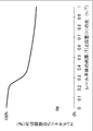
ここで、周壁の内周面とレール本体の内周面との境界部分に形成される段差をh、レール本体の肉厚をTとした場合に、h/Tの値とエンドキャップの破壊圧力の大きさとの相関関係について試験を行った。尚、上記「エンドキャップの破壊圧力」とは、エンドキャップを破壊するために必要な圧力を意味し、レール本体の内周面と周壁の内周面との境界部分に段差がないh/T=0のときの破壊圧力を100%とした時の比率を意味する。そしてこの試験の結果を図6に示す。この試験の結果、h/T≦0.25の範囲でエンドキャップの破壊圧力は90%以上を示し、顕著に向上することが明らかとなった。
上記の結果から、h/Tの値を0<h/T≦0.25とすることにより、レール本体への圧力付加時にこの境界部分に集中して負荷がかかりにくいものとなる。そのため、高い圧力を付加した際にも境界部分における破損を防ぐことが可能となる。
また、レール本体は、端部の内周面にエンドキャップの周壁が配置されたものであっても良い。これにより、レール本体の内周に加工を施す必要がないため、製造を容易なものとすることができる。
また、レール本体は、端部内周に凹部が備えられ、この凹部内にエンドキャップの周壁が配置されるとともに、レール本体の内周面と周壁の内周面との間に段差が設けられたものであっても良い。これにより、エンドキャップの周壁を厚く形成してもレール本体の凹部によって境界部分の段差を低いものとすることができることから、使用するエンドキャップを強度の強いものとすることができる。
本願の第1、2発明は上記の如く、レール本体の内周面と周壁の内周面との境界部分に段差がない構造、あるいは周壁の内周面とレール本体の内周面との境界部分に形成される段差をh、レール本体の肉厚Tとした場合に、h/Tの値を、0<h/T≦0.25とした構造とすることにより、レール本体への圧力付加時にこの境界部分に集中して負荷がかかるという事態を回避することができる。そのため、レール本体内に高い圧力を付加した際にも、周壁の内周面とレール本体の内周面との境界部分における破損を防ぐことができる。
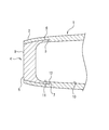
本願の第1発明である実施例1について、図1、2において以下に説明する。まず、(1)は筒型のレール本体であって、このレール本体(1)の端部(2)内周には、断面L字型の凹部(3)を内周方向に環状に備えている。またこのレール本体(1)の端部(2)にはエンドキャップ(4)を固定配置している。このエンドキャップ(4)は天板(5)と周壁(6)とから成り、この周壁(6)の肉厚を、上記凹部(3)の深さと略同一寸法としている。またこのエンドキャップ(4)の周壁(6)端面(7)から天板(5)表面(8)までの形成高さを、凹部(3)の軸方向の形成長さと略同一寸法としている。
そして、上記の如く形成したエンドキャップ(4)の周壁(6)を、レール本体(1)内の凹部(3)に、周壁(6)の端面(7)が凹部(3)の段部に当接するまで挿入配置する。これにより、レール本体(1)内の凹部(3)に周壁(6)が位置した状態となるとともに、上記の肉厚と凹部(3)の深さの寸法を略同一としていることから、図1に示す如く、レール本体(1)の内周面(10)とエンドキャップ(4)の内周面(11)との境界部分(12)に段差のない構造とすることができる。
従って、レール本体(1)に圧力を付加した際に、図2に示す如くレール本体(1)が半径方向に拡径するものとなる。しかしながら、レール本体(1)の内周面(10)と周壁(6)の内周面(11)との境界部分(12)には段差が形成されていないことから、この境界部分(12)に集中して負荷がかかるという事態は生じにくいものとなる。そのため、今後ガソリン直噴システムにおける高圧化が進んで燃料圧力が高くなった場合でも、高い圧力の付加に起因する境界部分(12)における破損を防ぐことが可能となる。
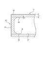
また上記実施例1では、レール本体(1)の凹部(3)内にエンドキャップ(4)の周壁(6)を挿入配置しているが、本実施例ではレール本体(21)に凹部を設けていない。本願の第2発明である実施例2について以下に説明すると、本実施例のレール本体(21)は円筒状であって、図3に示す如く内周面(27)に凹部等を形成するなどの加工を施していない。そしてこのレール本体(21)の端部(22)内周にエンドキャップ(23)を固定配置している。このエンドキャップ(23)は、天板(24)と周壁(25)とから成るものであって、その周壁(25)を上記レール本体(21)の端部(22)内周に挿入配置している。
そして図3に示す如く、この周壁(25)の内周面(26)とレール本体(21)の内周面(27)との段差をh、レール本体(21)の肉厚をTとした場合に、h/Tの値を0.2としている。そのため、本実施例ではh/Tの値が0<h/T≦0.25の範囲内にあることから、レール本体(21)内に圧力を付加した際に、図4に示す如くレール本体(21)が半径方向に拡径するものとなるが、周壁(25)の内周面(26)とレール本体(21)の内周面(27)との境界部分(28)に集中して負荷がかかりにくいものとなる。そのため、今後ガソリン直噴システムにおける高圧化が進んで燃料圧力が高くなった場合でも、高い圧力の付加に起因する境界部分(28)における破損を防ぐことが可能となる。
また上記の如く、レール本体(21)の内周面(27)に凹部を形成することなく、エンドキャップ(23)の周壁(25)を配置したものであるから、レール本体(21)の内周に加工を施す必要がないため、製造を容易なものとすることができる。
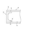
また上記実施例2では、凹部を形成していないレール本体(21)内にエンドキャップ(23)の周壁(25)を挿入配置しているが、本願の第2発明である実施例3ではレール本体(41)内に凹部(42)を設けるとともに、この凹部(42)内にエンドキャップ(43)の周壁(44)を挿入配置している。
本実施例について説明すると、本実施例のレール本体(41)の内周面(51)には、断面L字型の凹部(42)を内周方向に環状に設けている。またこのレール本体(41)の端部(45)にはエンドキャップ(43)を固定配置している。このエンドキャップ(43)は天板(46)と周壁(44)とから成るものであって、エンドキャップ(43)の周壁(44)端面(47)から天板(46)表面(48)までの形成高さを、凹部(42)の軸方向の形成長さと略同一寸法としている。
そして図5に示す如く、この周壁(44)の内周面(50)とレール本体(41)の内周面(51)との段差をh、レール本体(41)の肉厚をTとした場合に、h/Tの値を0.2としている。そのため、本実施例ではh/Tの値が0<h/T≦0.25の範囲内にあることから、レール本体(41)内に圧力を付加した際に、周壁(44)の内周面(50)とレール本体(41)の内周面(51)との境界部分(52)に集中して負荷がかかりにくいものとなる。そのため、今後ガソリン直噴システムにおける高圧化が進んで燃料圧力が高くなった場合でも、高い圧力の付加に起因する境界部分(52)における破損を防ぐことが可能となる。
また上記の如く、レール本体(41)の端部(45)内周に凹部(42)を形成し、この凹部(42)内にエンドキャップ(43)の周壁(44)を配置したものであるから、エンドキャップ(43)の周壁(44)を肉厚に形成しても、レール本体(41)の凹部(42)によって境界部分(52)の段差を低いものとすることができる。従って、エンドキャップ(43)の強度を高く維持した状態で耐圧性の高い製品を得ることができる。
1,21,41 レール本体
2,22,45 端部
3,42 凹部
4,23,43 エンドキャップ
5,24,46 天板
6,25,44 周壁
10,27,51 内周面(レール本体)
11,26,50 内周面(周壁)
12,28,52 境界部分
2,22,45 端部
3,42 凹部
4,23,43 エンドキャップ
5,24,46 天板
6,25,44 周壁
10,27,51 内周面(レール本体)
11,26,50 内周面(周壁)
12,28,52 境界部分
Claims (4)
- 天板と周壁とから成るエンドキャップと、このエンドキャップの周壁を端部に挿入配置したレール本体とが備えられたガソリン直噴レールにおいて、レール本体の端部内周に凹部が備えられるとともに、この凹部内に上記周壁が配置され、この周壁の内周面とレール本体の内周面との境界部分に段差がない構造としたことを特徴とするガソリン直噴レール。
- 天板と周壁とから成るエンドキャップと、このエンドキャップの周壁を端部に挿入配置したレール本体とが備えられたガソリン直噴レールにおいて、レール本体の端部内周にエンドキャップの周壁が位置するとともに、この周壁の内周面とレール本体の内周面との境界部分に形成される段差をh、レール本体の肉厚Tとした場合に、h/Tの値が、0<h/T≦0.25であることを特徴とするガソリン直噴レール。
- レール本体は、端部の内周面にエンドキャップの周壁が配置されたことを特徴とする請求項2のガソリン直噴レール。
- レール本体は、端部内周に凹部が備えられ、この凹部内にエンドキャップの周壁が配置されるとともに、レール本体の内周面と周壁の内周面との間に段差が設けられたことを特徴とする請求項2のガソリン直噴レール。
Priority Applications (5)
| Application Number | Priority Date | Filing Date | Title |
|---|---|---|---|
| CN201780051191.6A CN109844300B (zh) | 2016-08-25 | 2017-06-26 | 端盖 |
| KR1020197005949A KR102203440B1 (ko) | 2016-08-25 | 2017-06-26 | 엔드 캡 |
| US16/325,706 US11156194B2 (en) | 2016-08-25 | 2017-06-26 | End cap |
| EP17843191.2A EP3483422B1 (en) | 2016-08-25 | 2017-06-26 | End cap |
| MX2019002153A MX2019002153A (es) | 2016-08-25 | 2017-06-26 | Tapa terminal. |
Applications Claiming Priority (2)
| Application Number | Priority Date | Filing Date | Title |
|---|---|---|---|
| JP2016164517A JP6788431B2 (ja) | 2016-08-25 | 2016-08-25 | エンドキャップ |
| JP2016-164517 | 2016-08-25 |
Publications (1)
| Publication Number | Publication Date |
|---|---|
| WO2018037703A1 true WO2018037703A1 (ja) | 2018-03-01 |
Family
ID=61246591
Family Applications (1)
| Application Number | Title | Priority Date | Filing Date |
|---|---|---|---|
| PCT/JP2017/023404 Ceased WO2018037703A1 (ja) | 2016-08-25 | 2017-06-26 | エンドキャップ |
Country Status (7)
| Country | Link |
|---|---|
| US (1) | US11156194B2 (ja) |
| EP (1) | EP3483422B1 (ja) |
| JP (1) | JP6788431B2 (ja) |
| KR (1) | KR102203440B1 (ja) |
| CN (1) | CN109844300B (ja) |
| MX (1) | MX2019002153A (ja) |
| WO (1) | WO2018037703A1 (ja) |
Families Citing this family (1)
| Publication number | Priority date | Publication date | Assignee | Title |
|---|---|---|---|---|
| KR102098374B1 (ko) * | 2018-12-28 | 2020-05-26 | 주식회사 현대케피코 | 연료레일 구조 |
Citations (3)
| Publication number | Priority date | Publication date | Assignee | Title |
|---|---|---|---|---|
| JP2001193599A (ja) * | 2000-01-12 | 2001-07-17 | Keihin Corp | 多気筒エンジン用燃料噴射装置における燃料分配装置 |
| JP2004116334A (ja) * | 2002-09-25 | 2004-04-15 | Usui Kokusai Sangyo Kaisha Ltd | 燃料レール及び燃料レール用主管並びにこれらの製造方法 |
| US20150007796A1 (en) * | 2012-02-02 | 2015-01-08 | Benteler Automobiltechnik Gmbh | Fuel distributor bar |
Family Cites Families (18)
| Publication number | Priority date | Publication date | Assignee | Title |
|---|---|---|---|---|
| US5511527A (en) * | 1995-06-28 | 1996-04-30 | Siemens Automotive Corporation | Fuel rail assembly with crossover hose |
| US20060163243A1 (en) * | 2005-01-25 | 2006-07-27 | Stieler David C | Method of coupling fuel system components |
| EP2080894B1 (en) * | 2008-01-18 | 2011-10-12 | Continental Automotive GmbH | Fuel rail of a combustion engine |
| JP5510992B2 (ja) * | 2008-06-30 | 2014-06-04 | 臼井国際産業株式会社 | 高圧直噴内燃機関用燃料レール及びその製造方法 |
| KR101220013B1 (ko) * | 2011-02-24 | 2013-01-09 | 주식회사 현대케피코 | 차량용 연료레일 구조 |
| US9074565B2 (en) * | 2012-07-16 | 2015-07-07 | Denso International America, Inc. | Damped fuel delivery system |
| US9494118B2 (en) * | 2014-04-30 | 2016-11-15 | Hitachi Automotive Systems Americas Inc. | Fuel delivery system for an internal combustion engine |
| JP6406904B2 (ja) * | 2014-07-16 | 2018-10-17 | 臼井国際産業株式会社 | ガソリン直噴エンジン用燃料レールの端末シール構造 |
| JP2016020678A (ja) * | 2014-07-16 | 2016-02-04 | 臼井国際産業株式会社 | ガソリン直噴エンジン用燃料レールの端末シール構造 |
| JP2016037928A (ja) * | 2014-08-08 | 2016-03-22 | 臼井国際産業株式会社 | ガソリン直噴エンジン用燃料レールの端末シール構造 |
| CN105508105B (zh) * | 2014-09-25 | 2018-01-12 | 联合汽车电子有限公司 | 塑料油轨的端盖、油轨本体及两者的焊接方法 |
| KR20160069534A (ko) * | 2014-12-08 | 2016-06-17 | 주식회사 현대케피코 | 고강도 조립 구조를 갖는 연료레일 |
| JP6526473B2 (ja) * | 2015-04-27 | 2019-06-05 | 臼井国際産業株式会社 | ガソリン直噴エンジン用燃料レールの端末シール構造 |
| US9574534B2 (en) * | 2015-05-19 | 2017-02-21 | Millennium Industries Corporation | Reinforced end cap assembly for pressure vessel |
| US20170051715A1 (en) * | 2015-08-19 | 2017-02-23 | Hitachi Automotive Systems Americas Inc. | Fuel rail for an internal combustion engine |
| JP6744089B2 (ja) * | 2015-12-04 | 2020-08-19 | 臼井国際産業株式会社 | ガソリン直噴レール |
| JP6850089B2 (ja) * | 2016-08-05 | 2021-03-31 | 臼井国際産業株式会社 | エンドキャップ |
| DE102017122301B3 (de) * | 2017-09-26 | 2018-10-31 | Benteler Automobiltechnik Gmbh | Kraftstoffverteiler |
-
2016
- 2016-08-25 JP JP2016164517A patent/JP6788431B2/ja active Active
-
2017
- 2017-06-26 EP EP17843191.2A patent/EP3483422B1/en active Active
- 2017-06-26 KR KR1020197005949A patent/KR102203440B1/ko active Active
- 2017-06-26 US US16/325,706 patent/US11156194B2/en active Active
- 2017-06-26 CN CN201780051191.6A patent/CN109844300B/zh active Active
- 2017-06-26 WO PCT/JP2017/023404 patent/WO2018037703A1/ja not_active Ceased
- 2017-06-26 MX MX2019002153A patent/MX2019002153A/es unknown
Patent Citations (3)
| Publication number | Priority date | Publication date | Assignee | Title |
|---|---|---|---|---|
| JP2001193599A (ja) * | 2000-01-12 | 2001-07-17 | Keihin Corp | 多気筒エンジン用燃料噴射装置における燃料分配装置 |
| JP2004116334A (ja) * | 2002-09-25 | 2004-04-15 | Usui Kokusai Sangyo Kaisha Ltd | 燃料レール及び燃料レール用主管並びにこれらの製造方法 |
| US20150007796A1 (en) * | 2012-02-02 | 2015-01-08 | Benteler Automobiltechnik Gmbh | Fuel distributor bar |
Non-Patent Citations (1)
| Title |
|---|
| See also references of EP3483422A4 * |
Also Published As
| Publication number | Publication date |
|---|---|
| JP6788431B2 (ja) | 2020-11-25 |
| EP3483422C0 (en) | 2024-05-01 |
| JP2018031307A (ja) | 2018-03-01 |
| KR20190031560A (ko) | 2019-03-26 |
| EP3483422A1 (en) | 2019-05-15 |
| MX2019002153A (es) | 2019-07-01 |
| KR102203440B1 (ko) | 2021-01-15 |
| CN109844300B (zh) | 2021-07-13 |
| US20200149502A1 (en) | 2020-05-14 |
| CN109844300A (zh) | 2019-06-04 |
| EP3483422B1 (en) | 2024-05-01 |
| US11156194B2 (en) | 2021-10-26 |
| EP3483422A4 (en) | 2020-02-19 |
Similar Documents
| Publication | Publication Date | Title |
|---|---|---|
| DK3060816T3 (en) | Expansion anchor with expansion sleeve with high strength sections | |
| JP6499648B2 (ja) | コイルばね組立体 | |
| US10808663B2 (en) | End cap | |
| WO2011059026A1 (ja) | 自動車用の閉塞栓 | |
| EP3126730B1 (en) | Method for the production of a bushing for the connection of two tubular elements | |
| JP5025076B2 (ja) | 樹脂管の接続構造 | |
| JP2018031307A (ja) | エンドキャップ | |
| JP6744089B2 (ja) | ガソリン直噴レール | |
| CN105387076A (zh) | 滚动轴承 | |
| JP4880563B2 (ja) | スパークプラグ用の主体金具の製造方法 | |
| CN106461080A (zh) | 密封构造 | |
| JP6567761B2 (ja) | 緩衝ストッパー | |
| JP6313673B2 (ja) | 金具の製造方法、スパークプラグの製造方法、およびセンサの製造方法 | |
| US20180355829A1 (en) | High-pressure fuel injection pipe with connection head and method of molding connection head | |
| JP5798203B2 (ja) | スパークプラグ | |
| JP6429000B2 (ja) | ホース接続体の製造方法 | |
| US12000507B2 (en) | Pipe, spool forming die, and pipe manufacturing method | |
| JP6078978B2 (ja) | ホース継手用ニップル | |
| CN112585389A (zh) | 钢管用螺纹接头 | |
| JP3620829B2 (ja) | ブラインドナットのかしめ処理方法 | |
| JP6200255B2 (ja) | 金属二重管の製造方法 | |
| JP2016124579A (ja) | 二重筒体 | |
| CN205446373U (zh) | 新型t型套 | |
| JP2017026049A (ja) | オーバーフローチューブ | |
| WO2016078794A1 (de) | Zündkerze mit verbesserter verbindung zwischen isolator und gehäuse |
Legal Events
| Date | Code | Title | Description |
|---|---|---|---|
| 121 | Ep: the epo has been informed by wipo that ep was designated in this application |
Ref document number: 17843191 Country of ref document: EP Kind code of ref document: A1 |
|
| ENP | Entry into the national phase |
Ref document number: 2017843191 Country of ref document: EP Effective date: 20190205 |
|
| NENP | Non-entry into the national phase |
Ref country code: DE |
|
| ENP | Entry into the national phase |
Ref document number: 20197005949 Country of ref document: KR Kind code of ref document: A |