WO2018042631A1 - 3次元積層造形装置、3次元積層造形装置の制御方法および3次元積層造形装置の制御プログラム - Google Patents
3次元積層造形装置、3次元積層造形装置の制御方法および3次元積層造形装置の制御プログラム Download PDFInfo
- Publication number
- WO2018042631A1 WO2018042631A1 PCT/JP2016/075862 JP2016075862W WO2018042631A1 WO 2018042631 A1 WO2018042631 A1 WO 2018042631A1 JP 2016075862 W JP2016075862 W JP 2016075862W WO 2018042631 A1 WO2018042631 A1 WO 2018042631A1
- Authority
- WO
- WIPO (PCT)
- Prior art keywords
- modeling
- additive manufacturing
- light beam
- light
- dimensional
- Prior art date
- Legal status (The legal status is an assumption and is not a legal conclusion. Google has not performed a legal analysis and makes no representation as to the accuracy of the status listed.)
- Ceased
Links
Images






Classifications
-
- B—PERFORMING OPERATIONS; TRANSPORTING
- B29—WORKING OF PLASTICS; WORKING OF SUBSTANCES IN A PLASTIC STATE IN GENERAL
- B29C—SHAPING OR JOINING OF PLASTICS; SHAPING OF MATERIAL IN A PLASTIC STATE, NOT OTHERWISE PROVIDED FOR; AFTER-TREATMENT OF THE SHAPED PRODUCTS, e.g. REPAIRING
- B29C64/00—Additive manufacturing, i.e. manufacturing of three-dimensional [3D] objects by additive deposition, additive agglomeration or additive layering, e.g. by 3D printing, stereolithography or selective laser sintering
- B29C64/20—Apparatus for additive manufacturing; Details thereof or accessories therefor
- B29C64/264—Arrangements for irradiation
-
- B—PERFORMING OPERATIONS; TRANSPORTING
- B22—CASTING; POWDER METALLURGY
- B22F—WORKING METALLIC POWDER; MANUFACTURE OF ARTICLES FROM METALLIC POWDER; MAKING METALLIC POWDER; APPARATUS OR DEVICES SPECIALLY ADAPTED FOR METALLIC POWDER
- B22F10/00—Additive manufacturing of workpieces or articles from metallic powder
- B22F10/30—Process control
-
- B—PERFORMING OPERATIONS; TRANSPORTING
- B22—CASTING; POWDER METALLURGY
- B22F—WORKING METALLIC POWDER; MANUFACTURE OF ARTICLES FROM METALLIC POWDER; MAKING METALLIC POWDER; APPARATUS OR DEVICES SPECIALLY ADAPTED FOR METALLIC POWDER
- B22F12/00—Apparatus or devices specially adapted for additive manufacturing; Auxiliary means for additive manufacturing; Combinations of additive manufacturing apparatus or devices with other processing apparatus or devices
- B22F12/22—Driving means
- B22F12/224—Driving means for motion along a direction within the plane of a layer
-
- B—PERFORMING OPERATIONS; TRANSPORTING
- B22—CASTING; POWDER METALLURGY
- B22F—WORKING METALLIC POWDER; MANUFACTURE OF ARTICLES FROM METALLIC POWDER; MAKING METALLIC POWDER; APPARATUS OR DEVICES SPECIALLY ADAPTED FOR METALLIC POWDER
- B22F12/00—Apparatus or devices specially adapted for additive manufacturing; Auxiliary means for additive manufacturing; Combinations of additive manufacturing apparatus or devices with other processing apparatus or devices
- B22F12/40—Radiation means
- B22F12/49—Scanners
-
- B—PERFORMING OPERATIONS; TRANSPORTING
- B29—WORKING OF PLASTICS; WORKING OF SUBSTANCES IN A PLASTIC STATE IN GENERAL
- B29C—SHAPING OR JOINING OF PLASTICS; SHAPING OF MATERIAL IN A PLASTIC STATE, NOT OTHERWISE PROVIDED FOR; AFTER-TREATMENT OF THE SHAPED PRODUCTS, e.g. REPAIRING
- B29C64/00—Additive manufacturing, i.e. manufacturing of three-dimensional [3D] objects by additive deposition, additive agglomeration or additive layering, e.g. by 3D printing, stereolithography or selective laser sintering
- B29C64/10—Processes of additive manufacturing
- B29C64/141—Processes of additive manufacturing using only solid materials
- B29C64/153—Processes of additive manufacturing using only solid materials using layers of powder being selectively joined, e.g. by selective laser sintering or melting
-
- B—PERFORMING OPERATIONS; TRANSPORTING
- B29—WORKING OF PLASTICS; WORKING OF SUBSTANCES IN A PLASTIC STATE IN GENERAL
- B29C—SHAPING OR JOINING OF PLASTICS; SHAPING OF MATERIAL IN A PLASTIC STATE, NOT OTHERWISE PROVIDED FOR; AFTER-TREATMENT OF THE SHAPED PRODUCTS, e.g. REPAIRING
- B29C64/00—Additive manufacturing, i.e. manufacturing of three-dimensional [3D] objects by additive deposition, additive agglomeration or additive layering, e.g. by 3D printing, stereolithography or selective laser sintering
- B29C64/10—Processes of additive manufacturing
- B29C64/171—Processes of additive manufacturing specially adapted for manufacturing multiple 3D objects
- B29C64/176—Sequentially
-
- B—PERFORMING OPERATIONS; TRANSPORTING
- B29—WORKING OF PLASTICS; WORKING OF SUBSTANCES IN A PLASTIC STATE IN GENERAL
- B29C—SHAPING OR JOINING OF PLASTICS; SHAPING OF MATERIAL IN A PLASTIC STATE, NOT OTHERWISE PROVIDED FOR; AFTER-TREATMENT OF THE SHAPED PRODUCTS, e.g. REPAIRING
- B29C64/00—Additive manufacturing, i.e. manufacturing of three-dimensional [3D] objects by additive deposition, additive agglomeration or additive layering, e.g. by 3D printing, stereolithography or selective laser sintering
- B29C64/20—Apparatus for additive manufacturing; Details thereof or accessories therefor
- B29C64/264—Arrangements for irradiation
- B29C64/268—Arrangements for irradiation using laser beams; using electron beams [EB]
-
- B—PERFORMING OPERATIONS; TRANSPORTING
- B29—WORKING OF PLASTICS; WORKING OF SUBSTANCES IN A PLASTIC STATE IN GENERAL
- B29C—SHAPING OR JOINING OF PLASTICS; SHAPING OF MATERIAL IN A PLASTIC STATE, NOT OTHERWISE PROVIDED FOR; AFTER-TREATMENT OF THE SHAPED PRODUCTS, e.g. REPAIRING
- B29C64/00—Additive manufacturing, i.e. manufacturing of three-dimensional [3D] objects by additive deposition, additive agglomeration or additive layering, e.g. by 3D printing, stereolithography or selective laser sintering
- B29C64/30—Auxiliary operations or equipment
- B29C64/386—Data acquisition or data processing for additive manufacturing
- B29C64/393—Data acquisition or data processing for additive manufacturing for controlling or regulating additive manufacturing processes
-
- B—PERFORMING OPERATIONS; TRANSPORTING
- B29—WORKING OF PLASTICS; WORKING OF SUBSTANCES IN A PLASTIC STATE IN GENERAL
- B29C—SHAPING OR JOINING OF PLASTICS; SHAPING OF MATERIAL IN A PLASTIC STATE, NOT OTHERWISE PROVIDED FOR; AFTER-TREATMENT OF THE SHAPED PRODUCTS, e.g. REPAIRING
- B29C67/00—Shaping techniques not covered by groups B29C39/00 - B29C65/00, B29C70/00 or B29C73/00
-
- B—PERFORMING OPERATIONS; TRANSPORTING
- B33—ADDITIVE MANUFACTURING TECHNOLOGY
- B33Y—ADDITIVE MANUFACTURING, i.e. MANUFACTURING OF THREE-DIMENSIONAL [3D] OBJECTS BY ADDITIVE DEPOSITION, ADDITIVE AGGLOMERATION OR ADDITIVE LAYERING, e.g. BY 3D PRINTING, STEREOLITHOGRAPHY OR SELECTIVE LASER SINTERING
- B33Y10/00—Processes of additive manufacturing
-
- B—PERFORMING OPERATIONS; TRANSPORTING
- B33—ADDITIVE MANUFACTURING TECHNOLOGY
- B33Y—ADDITIVE MANUFACTURING, i.e. MANUFACTURING OF THREE-DIMENSIONAL [3D] OBJECTS BY ADDITIVE DEPOSITION, ADDITIVE AGGLOMERATION OR ADDITIVE LAYERING, e.g. BY 3D PRINTING, STEREOLITHOGRAPHY OR SELECTIVE LASER SINTERING
- B33Y30/00—Apparatus for additive manufacturing; Details thereof or accessories therefor
-
- B—PERFORMING OPERATIONS; TRANSPORTING
- B33—ADDITIVE MANUFACTURING TECHNOLOGY
- B33Y—ADDITIVE MANUFACTURING, i.e. MANUFACTURING OF THREE-DIMENSIONAL [3D] OBJECTS BY ADDITIVE DEPOSITION, ADDITIVE AGGLOMERATION OR ADDITIVE LAYERING, e.g. BY 3D PRINTING, STEREOLITHOGRAPHY OR SELECTIVE LASER SINTERING
- B33Y50/00—Data acquisition or data processing for additive manufacturing
- B33Y50/02—Data acquisition or data processing for additive manufacturing for controlling or regulating additive manufacturing processes
-
- B—PERFORMING OPERATIONS; TRANSPORTING
- B22—CASTING; POWDER METALLURGY
- B22F—WORKING METALLIC POWDER; MANUFACTURE OF ARTICLES FROM METALLIC POWDER; MAKING METALLIC POWDER; APPARATUS OR DEVICES SPECIALLY ADAPTED FOR METALLIC POWDER
- B22F10/00—Additive manufacturing of workpieces or articles from metallic powder
- B22F10/20—Direct sintering or melting
- B22F10/28—Powder bed fusion, e.g. selective laser melting [SLM] or electron beam melting [EBM]
-
- B—PERFORMING OPERATIONS; TRANSPORTING
- B22—CASTING; POWDER METALLURGY
- B22F—WORKING METALLIC POWDER; MANUFACTURE OF ARTICLES FROM METALLIC POWDER; MAKING METALLIC POWDER; APPARATUS OR DEVICES SPECIALLY ADAPTED FOR METALLIC POWDER
- B22F12/00—Apparatus or devices specially adapted for additive manufacturing; Auxiliary means for additive manufacturing; Combinations of additive manufacturing apparatus or devices with other processing apparatus or devices
- B22F12/40—Radiation means
- B22F12/44—Radiation means characterised by the configuration of the radiation means
- B22F12/45—Two or more
-
- B—PERFORMING OPERATIONS; TRANSPORTING
- B22—CASTING; POWDER METALLURGY
- B22F—WORKING METALLIC POWDER; MANUFACTURE OF ARTICLES FROM METALLIC POWDER; MAKING METALLIC POWDER; APPARATUS OR DEVICES SPECIALLY ADAPTED FOR METALLIC POWDER
- B22F12/00—Apparatus or devices specially adapted for additive manufacturing; Auxiliary means for additive manufacturing; Combinations of additive manufacturing apparatus or devices with other processing apparatus or devices
- B22F12/40—Radiation means
- B22F12/46—Radiation means with translatory movement
-
- Y—GENERAL TAGGING OF NEW TECHNOLOGICAL DEVELOPMENTS; GENERAL TAGGING OF CROSS-SECTIONAL TECHNOLOGIES SPANNING OVER SEVERAL SECTIONS OF THE IPC; TECHNICAL SUBJECTS COVERED BY FORMER USPC CROSS-REFERENCE ART COLLECTIONS [XRACs] AND DIGESTS
- Y02—TECHNOLOGIES OR APPLICATIONS FOR MITIGATION OR ADAPTATION AGAINST CLIMATE CHANGE
- Y02P—CLIMATE CHANGE MITIGATION TECHNOLOGIES IN THE PRODUCTION OR PROCESSING OF GOODS
- Y02P10/00—Technologies related to metal processing
- Y02P10/25—Process efficiency
Definitions
- the present invention relates to a control method for a three-dimensional additive manufacturing apparatus, a control method for the three-dimensional additive manufacturing apparatus, and a control program for the three-dimensional additive manufacturing apparatus.
- Patent Document 1 discloses a three-dimensional additive manufacturing apparatus that stops the entire apparatus and performs modeling setup and maintenance, material replacement, and the like.
- An object of the present invention is to provide a technique for solving the above-described problems.
- a three-dimensional additive manufacturing apparatus Multiple modeling rooms; At least one material supply means for supplying the material of the three-dimensional layered object to the modeling table in the modeling chamber; At least one light irradiation means for irradiating the material with light; Control means for controlling the material supply means and the light irradiation means; With When the material is supplied onto one modeling table by the material supply unit, the control unit controls the light irradiation unit to irradiate the light beam on the other modeling table.
- a method for controlling a three-dimensional additive manufacturing apparatus includes: Multiple modeling rooms; At least one material supply means for supplying the material of the three-dimensional layered object to the modeling table in the modeling chamber; At least one light irradiation means for irradiating the material with light;
- a method for controlling a three-dimensional additive manufacturing apparatus comprising: A first step of supplying a first material to the modeling table in the first modeling chamber and irradiating the second material in the second modeling chamber with the light beam irradiation unit; A second step of supplying a second material to the modeling table in the second modeling chamber, and irradiating the first material in the first modeling chamber with the light irradiation unit; A third step of repeating the first step and the second step while moving the light beam irradiation means; including.
- a control program for a three-dimensional additive manufacturing apparatus is: Multiple modeling rooms; At least one material supply means for supplying the material of the three-dimensional layered object to the modeling table in the modeling chamber; At least one light irradiation means for irradiating the material with light;
- a control program for a three-dimensional additive manufacturing apparatus comprising: A first step of supplying a first material to the modeling table in the first modeling chamber and irradiating the second material in the second modeling chamber with the light beam irradiation unit; A second step of supplying a second material to the modeling table in the second modeling chamber, and irradiating the first material in the first modeling chamber with the light irradiation unit; A third step of repeating the first step and the second step while moving the light beam irradiation means; Is executed on the computer.
- the three-dimensional additive manufacturing apparatus 100 is a powder bed type three-dimensional additive manufacturing apparatus that forms a three-dimensional additive manufacturing object by laying the material of the three-dimensional additive object on a modeling table and irradiating the spread material with light. .
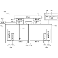
- 1A and 1B are plan views for explaining the outline of the configuration and operation of the three-dimensional additive manufacturing apparatus according to the present embodiment.
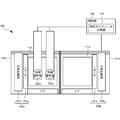
- 2A and 2B are front views for explaining the outline of the configuration and operation of the three-dimensional additive manufacturing apparatus according to this embodiment.
- the three-dimensional additive manufacturing apparatus 100 includes modeling chambers 101a and 101b, material supply units 102a and 102b, a light beam irradiation unit 103, and a control unit 104.
- the modeling chambers 101a and 101b further include modeling tables 111a and 111b.
- the modeling chamber 101a and the modeling chamber 101b are arranged side by side.
- the three-dimensional layered object is modeled on the modeling tables 111a and 111b.
- a three-dimensional layered object is formed by layering materials on the modeling tables 111a and 111b, irradiating the spread materials with light, and repeating the process of melting and solidifying the materials to form and stack the materials.
- the number of modeling rooms is not limited to two, and may be three or more. For example, it may be determined by increasing or decreasing the number of modeling rooms in accordance with the size of the three-dimensional layered object to be modeled.
- the layout of the modeling rooms may be various arrangements such as one-line arrangement (parallel arrangement), L-shaped arrangement, and C-shaped arrangement.
- the material supply units 102a and 102b further include material storage units 121a and 121b and recoaters 122a and 122b.
- the material storage units 121a and 121b store the material of the three-dimensional layered object and supply it to the recoaters 122a and 122b.
- the recoaters 122a and 122b spread the material supplied from the material storage units 121a and 121b on the modeling tables 111a and 111b.
- the recoaters 122a and 122b spread a layer of material.
- the recoaters 122a and 122b may lay together several layers of materials on the modeling tables 111a and 111b. Examples of the material include metal powder and resin powder, but are not limited thereto.
- the materials supplied to the modeling chamber 101a and the modeling chamber 101b may be the same material or different materials.
- the light beam irradiation unit 103 irradiates the material 131 spread on the modeling tables 111a and 111b with the light beam 131 to melt and solidify the material.
- the light beam 131 applied to the material is, for example, a laser beam, but is not limited thereto.
- the light irradiation unit 103 is shared by the modeling chamber 101a and the modeling chamber 101b. And if an expensive member like the light irradiation part 103 is made common in the some modeling chamber 101a, 101b, the manufacturing cost of a three-dimensional layered modeling apparatus can be reduced. For example, if a fume collector is attached to the light beam irradiation unit 103, the fume collector can be shared.
- the control unit 104 further includes a modeling schedule generation unit 141.
- the control unit 104 controls the material supply units 102a and 102b and the recoaters 122a and 122b to adjust the material supply amount and the supply timing. Further, the control unit 104 controls the light beam irradiation unit 103 to adjust the output (energy) of the light beam 131 and the irradiation time of the material 131 laid on the modeling tables 111a and 111b.
- the modeling schedule generation unit 141 generates a modeling schedule for modeling a three-dimensional layered object modeled in the modeling chambers 101a and 101b.
- the modeling schedule includes, for example, what kind of three-dimensional layered object is modeled in what modeling room at what timing, timing of setup, maintenance, material replenishment, and the like. Operation schedule.
- the control unit 104 controls the material supply units 102a and 102b and the light beam irradiation unit 103 according to the generated modeling schedule to model a three-dimensional layered object.
- the modeling schedule generation unit 141 may be an external configuration of the control unit 104.
- the three-dimensional additive manufacturing apparatus 100 operates as shown in FIGS. 1A to 2B.
- FIG. 1A (FIG. 2A)
- setup for modeling a three-dimensional layered object, removal of a completed three-dimensional layered object, and the like are performed in one modeling chamber 101a.
- the setup is, for example, filling the material storage unit 121a with a material, cleaning the interior of the modeling chamber 101a, or performing maintenance, but is not limited thereto.
- the light irradiation unit 103 irradiates the material with the light beam 131 to melt and solidify the material, thereby modeling the three-dimensional layered object. Is done.
- the light irradiation unit 103 moves to the modeling chamber 101a side.
- the light beam irradiation unit 103 irradiates the material with a light beam 131. Then, the material irradiated with the light beam 131 is melted and solidified to form a three-dimensional layered object. In parallel with this, the completed three-dimensional layered object is taken out from the modeling chamber 101b that has been modeling the three-dimensional layered object, and preparation, cleaning, maintenance, etc. are performed in preparation for the next modeling. Is called.
- the three-dimensional additive manufacturing apparatus 100 repeats the above operation.
- the three-dimensional additive manufacturing apparatus 100 performs the same operation.
- the case where the number of the light irradiation units 103 is one has been described.
- the three-dimensional additive manufacturing apparatus 100 performs the same operation.
- the number of modeling rooms is N
- the number (M) of the light irradiation units 103 is preferably M ⁇ N.
- FIG. 3 is a diagram for explaining the downtime in the three-dimensional additive manufacturing apparatus 100 according to the present embodiment.
- the down time refers to a time other than the time during which the material is irradiated with light and sintered.
- FIG. 3 shows the work contents in the respective modeling chambers 101a and 101b in the case of modeling two three-dimensional layered objects using the two modeling chambers 101a and 101b (two modeling tables 111a and 111b). Has been.
- setup is performed, and the material is irradiated with the light beam 131, and the material is sintered (melted and solidified). Then, while the material is being sintered in the modeling chamber 101a, setup or the like is performed in the modeling chamber 101b.
- the material sintering is completed in the modeling chamber 101a and the three-dimensional layered object is completed, the material sintering is started in the modeling chamber 101b, and the three-dimensional layered object is modeled. Then, while the material is being sintered in the modeling chamber 101b, the completed three-dimensional layered object is taken out from the modeling chamber 101a, and is prepared for the next modeling.
- the light irradiation unit 103 Since the three-dimensional additive manufacturing apparatus 100 operates in this manner, the light irradiation unit 103 is always in operation (sintering is continued), and the light irradiation unit 103 is not in operation, that is, three-dimensional stacking. Downtime, which is a state where the entire modeling apparatus 100 is stopped, is reduced.
- FIG. 4 is a diagram illustrating an example of a modeling schedule table 401 provided in the three-dimensional additive manufacturing apparatus 100 according to the present embodiment.
- the modeling schedule table 401 is a table that stores a modeling schedule, and stores a schedule 412 in association with a modeling room ID (Identifier) 411.
- “ ⁇ ” indicates a light irradiation process (sintering process) in which the light beam 131 is irradiated to melt and solidify the material, and “ ⁇ ” indicates a process in which the light beam 131 is not irradiated (setup or removal of a three-dimensional layered object). Process).
- the modeling room with the modeling room ID P001 is irradiated with the light beam 131, and the modeling room with the modeling room ID P002 has a schedule for setup.
- the modeling room ID is P002.
- the modeling room ID is P002.
- the modeling room ID is P001.
- FIG. 5 is a diagram illustrating a hardware configuration of the control unit 104 of the three-dimensional additive manufacturing apparatus 100 according to the present embodiment.
- a CPU (Central Processing Unit) 510 is a processor for calculation control, and implements a functional component of the control unit 104 of the three-dimensional additive manufacturing apparatus 100 of FIGS. 1A to 2B by executing a program.
- a ROM (Read Only Memory) 520 stores fixed data such as initial data and programs and other programs.
- the network interface 530 communicates with other devices via the network. Note that the number of CPUs 510 is not limited to one, and a plurality of CPUs may be included, or a GPU (Graphics Processing Unit) for image processing may be included.
- GPU Graphics Processing Unit
- the network interface 530 preferably includes a CPU independent of the CPU 510 and writes or reads transmission / reception data in a RAM (Random Access Memory) 540 area. Also, it is desirable to provide a DMAC (Direct Memory Access Controller) that transfers data between the RAM 540 and the storage 550 (not shown). Furthermore, the input / output interface 560 preferably has a CPU independent of the CPU 510 and writes or reads input / output data in the RAM 540 area. Therefore, the CPU 510 recognizes that the data has been received or transferred to the RAM 540 and processes the data. Further, the CPU 510 prepares the processing result in the RAM 540 and leaves the subsequent transmission or transfer to the network interface 530, the DMAC, or the input / output interface 560.
- a CPU independent of the CPU 510 and writes or reads transmission / reception data in a RAM (Random Access Memory) 540 area.
- DMAC Direct Memory Access Controller
- the RAM 540 is a random access memory used by the CPU 510 as a temporary storage work area. In the RAM 540, an area for storing data necessary for realizing the present embodiment is secured.
- the modeling model 541 is data obtained by modeling a three-dimensional layered object output from CAD (Computer Aided Design) or CAM (Computer Aided Manufacturing).
- the three-dimensional layered modeling apparatus 100 is based on the modeling model 541.
- the modeling schedule 542 is data related to the modeling schedule of the three-dimensional layered object generated based on the modeling model 541, and is data developed from the modeling schedule table 401, for example.
- the input / output data 543 is data input / output via the input / output interface 560.
- Transmission / reception data 544 is data transmitted / received via the network interface 530.
- the RAM 540 has an application execution area 545 for executing various application modules.
- the storage 550 stores a database, various parameters, or the following data or programs necessary for realizing the present embodiment.
- the storage 550 stores a modeling schedule table 401.
- the modeling schedule table 401 is a table for managing the relationship between the modeling room ID 411 and the schedule 412 shown in FIG.
- the storage 550 further stores a control module 552 and a modeling schedule generation module 553. These modules are executed by the CPU 510.
- the control module 552 is a module that controls the material supply units 102 a and 102 b and the light beam irradiation unit 103.
- the modeling schedule generation module 553 is a module that generates a modeling schedule for a three-dimensional layered object. These modules 552 to 553 are read by the CPU 510 into the application execution area 548 of the RAM 540 and executed.
- the control program 554 is a program for controlling the entire three-dimensional additive manufacturing apparatus 100.
- the input / output interface 560 interfaces input / output data with input / output devices.
- a display unit 561 and an operation unit 562 are connected to the input / output interface 560.
- a storage medium 564 may be further connected to the input / output interface 560.
- a speaker 563 that is an audio output unit and a microphone that is an audio input unit may be connected.
- the RAM 540 and the storage 550 illustrated in FIG. 5 do not illustrate general-purpose functions included in the control unit 104 of the three-dimensional additive manufacturing apparatus 100 and programs and data related to other realizable functions.
- FIG. 6 is a flowchart for explaining the processing procedure of the three-dimensional additive manufacturing apparatus 100 according to the present embodiment. This flowchart is executed by the CPU 510 in FIG. 5 using the RAM 540, and implements the functional components of the three-dimensional additive manufacturing apparatus 100 in FIGS. 1A to 2B.
- step S601 the three-dimensional additive manufacturing apparatus 100 supplies the first material to the modeling table 111a in the modeling chamber 101a (first modeling chamber), and the light beam 131 is applied to the second material in the modeling chamber 101b (second modeling chamber). Irradiate.
- step S603 the three-dimensional additive manufacturing apparatus 100 determines whether the formation of the three-dimensional additive manufacturing object in the modeling chamber 101b is completed. When it is determined that the modeling is not completed (NO in step S603), the three-dimensional layered modeling apparatus 100 returns to step S601 and repeats the subsequent steps. When it is determined that the modeling is completed (YES in step S603), the three-dimensional layered modeling apparatus 100 proceeds to step S605.
- step S605 the three-dimensional additive manufacturing apparatus 100 supplies the second material to the modeling table 111b in the modeling chamber 101b, and irradiates the first material in the modeling chamber 101a with the light beam 131.
- step S607 the three-dimensional additive manufacturing apparatus 100 determines whether the formation of the three-dimensional additive manufacturing object in the modeling chamber 101a is completed. When it is determined that the modeling is not completed (NO in step S607), the three-dimensional layered modeling apparatus 100 returns to step S605 and repeats the subsequent steps. If it is determined that modeling has been completed (YES in step S607), the process proceeds to step S609. In step S ⁇ b> 609, the three-dimensional additive manufacturing apparatus 100 determines whether or not all modeling has been completed.
- step S609 If it is determined that all modeling has not been completed (NO in step S609), the process returns to step S601 and the subsequent steps are repeated. When it is determined that all modeling has been completed (YES in step S609), the three-dimensional additive manufacturing apparatus 100 ends the process.
- the stop time (downtime) of the entire apparatus due to maintenance or material replacement.
- irradiation with light and setup are performed alternately, so that downtime can be reduced. That is, since a plurality of modeling rooms are connected to share a light irradiation unit, downtime can be reduced. Therefore, the light beam irradiation unit, which is an expensive member, can be operated efficiently without waste.
- the modeling time of a three-dimensional layered object can also be shortened. Furthermore, by changing the material supplied to the modeling room, it is possible to model a three-dimensional modeled object with different materials. Further, by increasing the number of modeling rooms, even a larger three-dimensional layered object can be modeled.
- FIGS. 7A to 8B are plan views for explaining the outline of the configuration and operation of the three-dimensional additive manufacturing apparatus 700 according to this embodiment.
- 8A and 8B are front views for explaining the outline of the configuration and operation of the three-dimensional additive manufacturing apparatus according to the present embodiment.
- the three-dimensional additive manufacturing apparatus 700 according to the present embodiment is different from the first embodiment in that it has two light irradiation units. Since other configurations and operations are the same as those in the first embodiment, the same configurations and operations are denoted by the same reference numerals, and detailed description thereof is omitted.
- the three-dimensional additive manufacturing apparatus 700 includes a light beam irradiation unit 703a and a light beam irradiation unit 703b.
- the three-dimensional additive manufacturing apparatus 700 irradiates the material with light beams 731a and 731b using the light beam irradiation units 703a and 703b.
- one of the modeling chambers 101a and 101b may be irradiated with the light beams 731a and 731b by the two light beam irradiation units 703a and 703b, but the method of irradiating the light beams 731a and 731b is not limited thereto.
- the modeling chamber 101a may be irradiated with the light beam 731a by the light beam irradiation unit 703a, and the light beam 731b may be irradiated to the modeling chamber 101b by the light beam irradiation unit 703b.
- the number of the light irradiation units 703a and 703b is described as two. However, the number of the light irradiation units 703a and 703b is not limited to this, and may be three or more. The combination of the number of modeling chambers 101a and 101b and the number of light irradiation units 703a and 703b may be any combination.
- the stop time (downtime) of the entire apparatus due to maintenance or material replacement. Further, since the number of the light irradiation parts is two, the material is melted using the two light irradiation parts at the same time, so that the modeling (sintering) time can be halved. Further, if the number of light irradiation parts is N (N ⁇ 3), the modeling time can be reduced to 1 / N.
- FIG. 9 is a front view for explaining the outline of the configuration and operation of the three-dimensional additive manufacturing apparatus 900 according to this embodiment.
- the three-dimensional additive manufacturing apparatus 900 according to the present embodiment is different from the first and second embodiments in that it includes a light source, a galvano mirror, a driving unit, and a moving unit. Since other configurations and operations are the same as those in the first embodiment and the second embodiment, the same configurations and operations are denoted by the same reference numerals, and detailed description thereof is omitted.
- the three-dimensional additive manufacturing apparatus 900 includes a light source 903, a galvano mirror 906, a driving unit 907, and a moving unit 908 instead of the light beam irradiation unit 103.
- the light source 903 generates a light beam 931 such as a laser beam.
- the light beam 931 generated by the light source 903 is applied to the material on the modeling tables 111a and 111b via the galvanometer mirror.
- the drive unit 907 controls the movement of the galvano mirror 906 to change the direction of the galvano mirror 906 and adjust the path of the light beam 931 generated by the light source 903.
- the moving unit 908 moves the galvanometer mirror 906 to move between the modeling chambers 101a and 101b.
- the moving unit 908 is, for example, a slide rail or a linear rail, but is not limited thereto.
- the number of galvanometer mirrors 906 may be two. In this case, as the operation mode of the galvanometer mirror 906, for example, two in the modeling chamber 101a.
- the galvanometer mirror 906 may be used to irradiate the light beam 931.
- each modeling chamber 101a, 101b may be irradiated with the light beam 931 by using one galvanometer mirror 906.
- the number of galvanometer mirrors 906 may be three or more. As described above, if the number of galvano mirrors 906 is increased, the irradiation time of the light beam 931 can be shortened, so that the modeling time of the three-dimensional layered object can be shortened.
- the stop time (downtime) of the entire apparatus due to maintenance or material replacement.
- the galvanometer mirror since the galvanometer mirror is used, the irradiation direction of the light beam can be controlled at high speed, and the galvanometer mirror can be moved at high speed. Furthermore, if the number of galvanometer mirrors is increased, the modeling time can be shortened.
- the three-dimensional additive manufacturing apparatus according to the present embodiment corresponds to an embodiment in which the number of modeling chambers and the number of light irradiation units are changed in the three-dimensional additive manufacturing apparatus shown in the first to third embodiments. .
- FIGS. 10A to 10C are diagrams illustrating examples of the modeling schedule tables 1101, 1102, and 1103 provided in the three-dimensional additive manufacturing apparatus according to the present embodiment.
- FIG. 10A shows an example in which there is one light irradiation unit 103 and three modeling rooms.
- FIG. 10B shows an example in which there are two light beam irradiation units 103 and three modeling rooms.
- FIG. 10C shows an example in which there are two light irradiation units 103 and four modeling rooms.
- the modeling schedule tables 1101, 1102, and 1103 store schedules 1112, 1122, and 1132 in association with modeling room IDs 1111, 1121, and 1131.
- the modeling room with the modeling room ID P001 is irradiated with light, and in the modeling room with the modeling room IDs P002 and P003, the setup is performed.
- the modeling room whose modeling room ID is P002 is irradiated with light, and in the modeling room whose modeling room IDs are P001 and P003, setup is performed.
- the modeling room whose modeling room ID is P003 is irradiated with light, and in the modeling room whose modeling room IDs are P001 and P002, setup is performed.
- the above schedule may be executed repeatedly, or a changed schedule may be executed.
- the modeling room with the modeling room IDs P001 and P002 is irradiated with light, and in the modeling room with the modeling room ID P003, setup is performed. ing.
- the modeling room with the modeling room IDs P002 and P003 is irradiated with light, and in the modeling room with the modeling room ID P001, setup is performed.
- the modeling room with the modeling room IDs P001 and P003 is irradiated with light, and the modeling room with the modeling room ID P002 has a schedule for setup and the like.
- the above schedule may be executed repeatedly, or a changed schedule may be executed.
- a light beam is irradiated to the modeling room with the modeling room IDs P001 and P002, and the setup or the like is performed in the modeling room with the modeling room IDs P003 and P004. It has become.
- the modeling room with the modeling room IDs P003 and P004 is irradiated with light, and the modeling room with the modeling room IDs P001 and P002 has a schedule for setup.
- the above schedule may be executed repeatedly, or a changed schedule may be executed.
- a modeling schedule table can be created similarly.
- the method shown in the first to third embodiments can be applied, so that maintenance or It is possible to reduce the downtime of the entire apparatus due to the exchange of materials.
- the present invention may be applied to a system composed of a plurality of devices, or may be applied to a single device. Furthermore, the present invention can also be applied to a case where an information processing program that implements the functions of the embodiments is supplied directly or remotely to a system or apparatus. Therefore, in order to realize the functions of the present invention on a computer, a program installed on the computer, a medium storing the program, and a WWW (World Wide Web) server that downloads the program are also included in the scope of the present invention. . In particular, at least a non-transitory computer readable medium storing a program for causing a computer to execute the processing steps included in the above-described embodiments is included in the scope of the present invention.
Landscapes
- Engineering & Computer Science (AREA)
- Materials Engineering (AREA)
- Chemical & Material Sciences (AREA)
- Manufacturing & Machinery (AREA)
- Mechanical Engineering (AREA)
- Physics & Mathematics (AREA)
- Optics & Photonics (AREA)
- Toxicology (AREA)
- Health & Medical Sciences (AREA)
- Automation & Control Theory (AREA)
- General Health & Medical Sciences (AREA)
- Plasma & Fusion (AREA)
- Powder Metallurgy (AREA)
Abstract
Description
複数の造形室と、
前記造形室内の造形台へ3次元積層造形物の材料を供給する少なくとも1つの材料供給手段と、
前記材料へ光線を照射する少なくとも1つの光線照射手段と、
前記材料供給手段および前記光線照射手段を制御する制御手段と、
を備え、
前記制御手段は、前記材料供給手段により、一方の造形台上に前記材料を供給している場合、前記光線照射手段により、他方の造形台上に前記光線を照射するよう制御する。
複数の造形室と、
前記造形室内の造形台へ3次元積層造形物の材料を供給する少なくとも1つの材料供給手段と、
前記材料へ光線を照射する少なくとも1つの光線照射手段と、
を備える3次元積層造形装置の制御方法であって、
第1材料供給手段が、第1造形室の造形台へ第1材料を供給し、第2造形室の第2材料に前記光線照射手段で光線を照射する第1ステップと、
第2材料供給手段が、前記第2造形室の造形台へ前記第2材料を供給し、前記第1造形室の前記第1材料に前記光線照射手段で光線を照射する第2ステップと、
前記光線照射手段を移動させながら、前記第1ステップと前記第2ステップとを繰り返す第3ステップと、
を含む。
複数の造形室と、
前記造形室内の造形台へ3次元積層造形物の材料を供給する少なくとも1つの材料供給手段と、
前記材料へ光線を照射する少なくとも1つの光線照射手段と、
を備える3次元積層造形装置の制御プログラムであって、
第1材料供給手段が、第1造形室の造形台へ第1材料を供給し、第2造形室の第2材料に前記光線照射手段で光線を照射する第1ステップと、
第2材料供給手段が、前記第2造形室の造形台へ前記第2材料を供給し、前記第1造形室の前記第1材料に前記光線照射手段で光線を照射する第2ステップと、
前記光線照射手段を移動させながら、前記第1ステップと前記第2ステップとを繰り返す第3ステップと、
をコンピュータに実行させる。
本発明の第1実施形態としての3次元積層造形装置100について、図1A乃至図5を用いて説明する。3次元積層造形装置100は、造形台上に3次元積層造形物の材料を敷き詰め、敷き詰めた材料に光線を照射して3次元積層造形物を造形するパウダーベッド方式の3次元積層造形装置である。
3次元積層造形装置100は、造形室101a,101bと、材料供給部102a,102bと、光線照射部103と、制御部104とを含む。造形室101a,101bは、さらに、造形台111a,111bを有する。また、造形室101aと造形室101bとは、並んで配置されている。3次元積層造形物は、造形台111a,111b上に造形される。3次元積層造形物は、造形台111a,111b上に一層分の材料を敷き詰め、敷き詰めた材料に光線を照射して、材料を溶融、凝固させる過程を繰り返すことにより材料が積み重ねられて、造形される。
3次元積層造形装置100は、図1A乃至図2Bに示したように動作する。図1A(図2A)に示したように、一方の造形室101aでは、3次元積層造形物を造形するための段取りや、完成した3次元積層造形物の取り出しなどを行う。段取りは、例えば、材料貯蔵部121aに材料を充填したり、造形室101a内を清掃したり、メンテナンスを行ったりすることであるが、これらには限定されない。
次に本発明の第2実施形態に係る3次元積層造形装置について、図7A乃至図8Bを用いて説明する。図7Aおよび図7Bは、本実施形態に係る3次元積層造形装置700の構成および動作の概略を説明する平面図である。図8Aおよび図8Bは、本実施形態に係る3次元積層造形装置の構成および動作の概略を説明する正面図である。
次に本発明の第3実施形態に係る3次元積層造形装置について、図9を用いて説明する。図9は、本実施形態に係る3次元積層造形装置900の構成および動作の概略を説明する正面図である。本実施形態に係る3次元積層造形装置900は、上記第1実施形態および第2実施形態と比べると、光源とガルバノミラーと駆動部と移動部とを有する点で異なる。その他の構成および動作は、第1実施形態および第2実施形態と同様であるため、同じ構成および動作については同じ符号を付してその詳しい説明を省略する。
次に本発明の第4実施形態に係る3次元積層造形装置について、図10A乃至図10Cを用いて説明する。本実施形態に係る3次元積層造形装置は、上記第1実施形態乃至第3実施形態に示した3次元積層造形装置において、造形室の数や光線照射部の数を変更した実施形態に相当する。
以上、実施形態を参照して本願発明を説明したが、本願発明は上記実施形態に限定されるものではない。本願発明の構成や詳細には、本願発明のスコープ内で当業者が理解し得る様々な変更をすることができる。また、それぞれの実施形態に含まれる別々の特徴を如何様に組み合わせたシステムまたは装置も、本発明の範疇に含まれる。
Claims (9)
- 複数の造形室と、
前記造形室内の造形台へ3次元積層造形物の材料を供給する少なくとも1つの材料供給手段と、
前記材料へ光線を照射する少なくとも1つの光線照射手段と、
前記材料供給手段および前記光線照射手段を制御する制御手段と、
を備え、
前記制御手段は、前記材料供給手段により、一方の造形台上に前記材料を供給している場合、前記光線照射手段により、他方の造形台上に前記光線を照射するよう制御する3次元積層造形装置。 - 前記光線照射手段は、前記複数の造形室間を移動可能である請求項1に記載の3次元積層造形装置。
- 前記制御手段は、一方の造形室において、前記3次元積層造形物の造形が完了したタイミングで、他方の造形室に前記光線照射手段を移動させる請求項1または2に記載の3次元積層造形装置。
- 前記制御手段は、一方の造形室において、少なくとも一層分の材料への前記光線の照射が完了したタイミングで、他方の造形室に前記光線照射手段を移動させる請求項1または2に記載の3次元積層造形装置。
- 前記光線照射手段は、
1つの光源と、
少なくとも1つのガルバノミラーと、
前記ガルバノミラーを駆動して、前記造形台上に前記光線を誘導する駆動手段と、
を含み、
前記制御手段は、前記ガルバノミラーを前記複数の造形室間を移動させる移動手段を有する請求項1乃至4のいずれか1項に記載の3次元積層造形装置。 - 前記移動手段は、スライドレールまたはリニアレールである請求項5に記載の3次元積層造形装置。
- 前記制御手段は、造形スケジュールを生成する造形スケジュール生成手段をさらに備え、前記造形スケジュールに基づいて、前記材料供給手段および前記光線照射手段を制御する請求項1乃至6のいずれか1項に記載の3次元積層造形装置。
- 複数の造形室と、
前記造形室内の造形台へ3次元積層造形物の材料を供給する少なくとも1つの材料供給手段と、
前記材料へ光線を照射する少なくとも1つの光線照射手段と、
を備える3次元積層造形装置の制御方法であって、
第1材料供給手段が、第1造形室の造形台へ第1材料を供給し、第2造形室の第2材料に前記光線照射手段で光線を照射する第1ステップと、
第2材料供給手段が、前記第2造形室の造形台へ前記第2材料を供給し、前記第1造形室の前記第1材料に前記光線照射手段で光線を照射する第2ステップと、
前記光線照射手段を移動させながら、前記第1ステップと前記第2ステップとを繰り返す第3ステップと、
を含む3次元積層造形装置の制御方法。 - 複数の造形室と、
前記造形室内の造形台へ3次元積層造形物の材料を供給する少なくとも1つの材料供給手段と、
前記材料へ光線を照射する少なくとも1つの光線照射手段と、
を備える3次元積層造形装置の制御プログラムであって、
第1材料供給手段が、第1造形室の造形台へ第1材料を供給し、第2造形室の第2材料に前記光線照射手段で光線を照射する第1ステップと、
第2材料供給手段が、前記第2造形室の造形台へ前記第2材料を供給し、前記第1造形室の前記第1材料に前記光線照射手段で光線を照射する第2ステップと、
前記光線照射手段を移動させながら、前記第1ステップと前記第2ステップとを繰り返す第3ステップと、
をコンピュータに実行させる3次元積層造形装置の制御プログラム。
Priority Applications (5)
| Application Number | Priority Date | Filing Date | Title |
|---|---|---|---|
| US15/513,434 US11077613B2 (en) | 2016-09-02 | 2016-09-02 | Three-dimensional laminating and shaping apparatus, control method of three-dimensional laminating and shaping apparatus, and control program of three-dimensional laminating and shaping apparatus |
| JP2017514586A JP6457073B2 (ja) | 2016-09-02 | 2016-09-02 | 3次元積層造形装置、3次元積層造形装置の制御方法および3次元積層造形装置の制御プログラム |
| EP16845353.8A EP3315294B1 (en) | 2016-09-02 | 2016-09-02 | Three-dimensional laminate molding device, control method of three-dimensional laminate molding device, and control program of three-dimensional laminate molding device |
| PCT/JP2016/075862 WO2018042631A1 (ja) | 2016-09-02 | 2016-09-02 | 3次元積層造形装置、3次元積層造形装置の制御方法および3次元積層造形装置の制御プログラム |
| ES16845353T ES2881458T3 (es) | 2016-09-02 | 2016-09-02 | Dispositivo de moldeo laminado tridimensional, procedimiento de control del dispositivo de moldeo laminado tridimensional y programa de control del dispositivo de moldeo laminado tridimensional |
Applications Claiming Priority (1)
| Application Number | Priority Date | Filing Date | Title |
|---|---|---|---|
| PCT/JP2016/075862 WO2018042631A1 (ja) | 2016-09-02 | 2016-09-02 | 3次元積層造形装置、3次元積層造形装置の制御方法および3次元積層造形装置の制御プログラム |
Publications (1)
| Publication Number | Publication Date |
|---|---|
| WO2018042631A1 true WO2018042631A1 (ja) | 2018-03-08 |
Family
ID=61301816
Family Applications (1)
| Application Number | Title | Priority Date | Filing Date |
|---|---|---|---|
| PCT/JP2016/075862 Ceased WO2018042631A1 (ja) | 2016-09-02 | 2016-09-02 | 3次元積層造形装置、3次元積層造形装置の制御方法および3次元積層造形装置の制御プログラム |
Country Status (5)
| Country | Link |
|---|---|
| US (1) | US11077613B2 (ja) |
| EP (1) | EP3315294B1 (ja) |
| JP (1) | JP6457073B2 (ja) |
| ES (1) | ES2881458T3 (ja) |
| WO (1) | WO2018042631A1 (ja) |
Families Citing this family (3)
| Publication number | Priority date | Publication date | Assignee | Title |
|---|---|---|---|---|
| PL3566869T3 (pl) * | 2018-05-08 | 2022-02-07 | 9328-8082 Québec Inc. | Modułowy system wytwarzania addywnego i powiązane sposoby ciągłej produkcji części |
| EP3810404A4 (en) | 2018-05-09 | 2022-02-09 | Applied Materials, Inc. | ADDITIONAL MANUFACTURING WITH A POLYGON SCANNER |
| KR102362216B1 (ko) * | 2020-12-10 | 2022-02-15 | 주식회사 신영 | 파우더 베드 융합 시스템 |
Citations (4)
| Publication number | Priority date | Publication date | Assignee | Title |
|---|---|---|---|---|
| JP2001150557A (ja) * | 1999-11-25 | 2001-06-05 | Matsushita Electric Works Ltd | 三次元形状造形物の製造方法 |
| JP2003245981A (ja) * | 2002-02-25 | 2003-09-02 | Matsushita Electric Works Ltd | 三次元形状造形物の製造方法及びその製造装置 |
| JP2009001900A (ja) * | 2007-05-23 | 2009-01-08 | Panasonic Electric Works Co Ltd | 三次元形状造形物の製造方法 |
| JP5108884B2 (ja) | 2006-07-27 | 2012-12-26 | アルカム アーベー | 3次元物体を生成する方法および装置 |
Family Cites Families (7)
| Publication number | Priority date | Publication date | Assignee | Title |
|---|---|---|---|---|
| DE10219984C1 (de) * | 2002-05-03 | 2003-08-14 | Bego Medical Ag | Vorrichtung und Verfahren zum Herstellen frei geformter Produkte |
| DE10235427A1 (de) * | 2002-08-02 | 2004-02-12 | Eos Gmbh Electro Optical Systems | Vorrichtung und Verfahren zum Herstellen von dreidimensionalen Objekten mittels eines generativen Fertigungsverfahrens |
| DE10342882A1 (de) * | 2003-09-15 | 2005-05-19 | Trumpf Werkzeugmaschinen Gmbh + Co. Kg | Vorrichtung und Verfahren zur Herstellung eines dreidimensionalen Formkörpers |
| DE202011003443U1 (de) * | 2011-03-02 | 2011-12-23 | Bego Medical Gmbh | Vorrichtung zur generativen Herstellung dreidimensionaler Bauteile |
| US8915728B2 (en) * | 2012-01-27 | 2014-12-23 | United Technologies Corporation | Multi-dimensional component build system and process |
| TWI718096B (zh) | 2014-04-23 | 2021-02-11 | 荷蘭商荷蘭Tno自然科學組織公司 | 用以藉由分層製造技術製作有形產品之生產線及方法 |
| US10272664B2 (en) * | 2015-01-14 | 2019-04-30 | Xactiv, Inc. | Fabrication of 3D objects via multiple build platforms |
-
2016
- 2016-09-02 EP EP16845353.8A patent/EP3315294B1/en active Active
- 2016-09-02 WO PCT/JP2016/075862 patent/WO2018042631A1/ja not_active Ceased
- 2016-09-02 US US15/513,434 patent/US11077613B2/en active Active
- 2016-09-02 ES ES16845353T patent/ES2881458T3/es active Active
- 2016-09-02 JP JP2017514586A patent/JP6457073B2/ja active Active
Patent Citations (4)
| Publication number | Priority date | Publication date | Assignee | Title |
|---|---|---|---|---|
| JP2001150557A (ja) * | 1999-11-25 | 2001-06-05 | Matsushita Electric Works Ltd | 三次元形状造形物の製造方法 |
| JP2003245981A (ja) * | 2002-02-25 | 2003-09-02 | Matsushita Electric Works Ltd | 三次元形状造形物の製造方法及びその製造装置 |
| JP5108884B2 (ja) | 2006-07-27 | 2012-12-26 | アルカム アーベー | 3次元物体を生成する方法および装置 |
| JP2009001900A (ja) * | 2007-05-23 | 2009-01-08 | Panasonic Electric Works Co Ltd | 三次元形状造形物の製造方法 |
Non-Patent Citations (1)
| Title |
|---|
| See also references of EP3315294A4 |
Also Published As
| Publication number | Publication date |
|---|---|
| US20180229431A1 (en) | 2018-08-16 |
| EP3315294A4 (en) | 2018-09-05 |
| ES2881458T3 (es) | 2021-11-29 |
| JPWO2018042631A1 (ja) | 2018-08-30 |
| EP3315294A1 (en) | 2018-05-02 |
| EP3315294B1 (en) | 2021-05-26 |
| JP6457073B2 (ja) | 2019-01-23 |
| US11077613B2 (en) | 2021-08-03 |
Similar Documents
| Publication | Publication Date | Title |
|---|---|---|
| Cai et al. | Using augmented reality to build digital twin for reconfigurable additive manufacturing system | |
| Gibson et al. | Development of additive manufacturing technology | |
| Duda et al. | 3D metal printing technology: the need to re-invent design practice | |
| Ian Gibson | Additive manufacturing technologies 3D printing, rapid prototyping, and direct digital manufacturing | |
| US10195692B2 (en) | Parallel direct metal laser melting | |
| Stucker | Additive manufacturing technologies: technology introduction and business implications | |
| CN105880593B (zh) | 多激光直线束印刷式扫描快速成形制造零件的设备及方法 | |
| Bandyopadhyay et al. | Global engineering and additive manufacturing | |
| Bin Ishak et al. | Robot arm platform for additive manufacturing using multi-plane toolpaths | |
| JP6457073B2 (ja) | 3次元積層造形装置、3次元積層造形装置の制御方法および3次元積層造形装置の制御プログラム | |
| Soler et al. | A generalized approach to non-layered fused filament fabrication | |
| JP6880218B2 (ja) | 物体を製造する方法、物体を製造するシステム、及び非一時的コンピュータ可読媒体 | |
| Chattopadhyay et al. | Advancements and challenges in additive manufacturing: a comprehensive review | |
| JP2019055584A (ja) | 先進付加製造のためのシステムおよび方法 | |
| Bandyopadhyay et al. | Introduction to additive manufacturing | |
| Gardiner et al. | FreeFab: Development of a construction-scale robotic formwork 3D printer | |
| Wilkinson et al. | 3D printing and sustainable product development | |
| CN106584840B (zh) | 一种单向大尺寸制件的3d打印方法及其打印装置 | |
| KR20150000606A (ko) | 스풀 제작도면 상에 생산에 필요한 각종 정보를 동적으로 결합하는 동적 결합시스템 및 그 방법 | |
| Dilberoglu et al. | Simulator of an additive and subtractive type of hybrid manufacturing system | |
| Popescu et al. | 3D printing bone models extracted from medical imaging data | |
| Shanmugam et al. | Developing robust 3D printed parts for automotive application using design for additive manufacturing and optimization techniques | |
| CN115352068A (zh) | 近净成型工艺及系统 | |
| Jumaah | A study on 3D printing and its effects on the future of transportation | |
| ARION et al. | 3D surface modelling aspects for 3D printing |
Legal Events
| Date | Code | Title | Description |
|---|---|---|---|
| WWE | Wipo information: entry into national phase |
Ref document number: 2017514586 Country of ref document: JP |
|
| WWE | Wipo information: entry into national phase |
Ref document number: 15513434 Country of ref document: US |
|
| REEP | Request for entry into the european phase |
Ref document number: 2016845353 Country of ref document: EP |
|
| WWE | Wipo information: entry into national phase |
Ref document number: 2016845353 Country of ref document: EP |
|
| 121 | Ep: the epo has been informed by wipo that ep was designated in this application |
Ref document number: 16845353 Country of ref document: EP Kind code of ref document: A1 |
|
| NENP | Non-entry into the national phase |
Ref country code: DE |