WO2018042793A1 - フレキシブルケーブル用コネクタ、フレキシブルケーブル用アダプタ、及び、フレキシブルケーブル - Google Patents
フレキシブルケーブル用コネクタ、フレキシブルケーブル用アダプタ、及び、フレキシブルケーブル Download PDFInfo
- Publication number
- WO2018042793A1 WO2018042793A1 PCT/JP2017/020593 JP2017020593W WO2018042793A1 WO 2018042793 A1 WO2018042793 A1 WO 2018042793A1 JP 2017020593 W JP2017020593 W JP 2017020593W WO 2018042793 A1 WO2018042793 A1 WO 2018042793A1
- Authority
- WO
- WIPO (PCT)
- Prior art keywords
- flexible cable
- connector
- housing
- frequency characteristic
- conductors
- Prior art date
- Legal status (The legal status is an assumption and is not a legal conclusion. Google has not performed a legal analysis and makes no representation as to the accuracy of the status listed.)
- Ceased
Links
Images






Classifications
-
- H—ELECTRICITY
- H01—ELECTRIC ELEMENTS
- H01R—ELECTRICALLY-CONDUCTIVE CONNECTIONS; STRUCTURAL ASSOCIATIONS OF A PLURALITY OF MUTUALLY-INSULATED ELECTRICAL CONNECTING ELEMENTS; COUPLING DEVICES; CURRENT COLLECTORS
- H01R12/00—Structural associations of a plurality of mutually-insulated electrical connecting elements, specially adapted for printed circuits, e.g. printed circuit boards [PCB], flat or ribbon cables, or like generally planar structures, e.g. terminal strips, terminal blocks; Coupling devices specially adapted for printed circuits, flat or ribbon cables, or like generally planar structures; Terminals specially adapted for contact with, or insertion into, printed circuits, flat or ribbon cables, or like generally planar structures
- H01R12/70—Coupling devices
- H01R12/77—Coupling devices for flexible printed circuits, flat or ribbon cables or like structures
- H01R12/771—Details
- H01R12/774—Retainers
-
- H—ELECTRICITY
- H01—ELECTRIC ELEMENTS
- H01R—ELECTRICALLY-CONDUCTIVE CONNECTIONS; STRUCTURAL ASSOCIATIONS OF A PLURALITY OF MUTUALLY-INSULATED ELECTRICAL CONNECTING ELEMENTS; COUPLING DEVICES; CURRENT COLLECTORS
- H01R12/00—Structural associations of a plurality of mutually-insulated electrical connecting elements, specially adapted for printed circuits, e.g. printed circuit boards [PCB], flat or ribbon cables, or like generally planar structures, e.g. terminal strips, terminal blocks; Coupling devices specially adapted for printed circuits, flat or ribbon cables, or like generally planar structures; Terminals specially adapted for contact with, or insertion into, printed circuits, flat or ribbon cables, or like generally planar structures
- H01R12/70—Coupling devices
- H01R12/77—Coupling devices for flexible printed circuits, flat or ribbon cables or like structures
- H01R12/771—Details
- H01R12/775—Ground or shield arrangements
-
- H—ELECTRICITY
- H01—ELECTRIC ELEMENTS
- H01R—ELECTRICALLY-CONDUCTIVE CONNECTIONS; STRUCTURAL ASSOCIATIONS OF A PLURALITY OF MUTUALLY-INSULATED ELECTRICAL CONNECTING ELEMENTS; COUPLING DEVICES; CURRENT COLLECTORS
- H01R12/00—Structural associations of a plurality of mutually-insulated electrical connecting elements, specially adapted for printed circuits, e.g. printed circuit boards [PCB], flat or ribbon cables, or like generally planar structures, e.g. terminal strips, terminal blocks; Coupling devices specially adapted for printed circuits, flat or ribbon cables, or like generally planar structures; Terminals specially adapted for contact with, or insertion into, printed circuits, flat or ribbon cables, or like generally planar structures
- H01R12/70—Coupling devices
- H01R12/77—Coupling devices for flexible printed circuits, flat or ribbon cables or like structures
- H01R12/79—Coupling devices for flexible printed circuits, flat or ribbon cables or like structures connecting to rigid printed circuits or like structures
-
- H—ELECTRICITY
- H01—ELECTRIC ELEMENTS
- H01R—ELECTRICALLY-CONDUCTIVE CONNECTIONS; STRUCTURAL ASSOCIATIONS OF A PLURALITY OF MUTUALLY-INSULATED ELECTRICAL CONNECTING ELEMENTS; COUPLING DEVICES; CURRENT COLLECTORS
- H01R13/00—Details of coupling devices of the kinds covered by groups H01R12/70 or H01R24/00 - H01R33/00
- H01R13/648—Protective earth or shield arrangements on coupling devices, e.g. anti-static shielding
- H01R13/658—High frequency shielding arrangements, e.g. against EMI [Electro-Magnetic Interference] or EMP [Electro-Magnetic Pulse]
- H01R13/6598—Shield material
- H01R13/6599—Dielectric material made conductive, e.g. plastic material coated with metal
-
- H—ELECTRICITY
- H01—ELECTRIC ELEMENTS
- H01R—ELECTRICALLY-CONDUCTIVE CONNECTIONS; STRUCTURAL ASSOCIATIONS OF A PLURALITY OF MUTUALLY-INSULATED ELECTRICAL CONNECTING ELEMENTS; COUPLING DEVICES; CURRENT COLLECTORS
- H01R12/00—Structural associations of a plurality of mutually-insulated electrical connecting elements, specially adapted for printed circuits, e.g. printed circuit boards [PCB], flat or ribbon cables, or like generally planar structures, e.g. terminal strips, terminal blocks; Coupling devices specially adapted for printed circuits, flat or ribbon cables, or like generally planar structures; Terminals specially adapted for contact with, or insertion into, printed circuits, flat or ribbon cables, or like generally planar structures
- H01R12/50—Fixed connections
- H01R12/59—Fixed connections for flexible printed circuits, flat or ribbon cables or like structures
- H01R12/594—Fixed connections for flexible printed circuits, flat or ribbon cables or like structures for shielded flat cable
Definitions
- the present invention relates to a flexible cable connector, a flexible cable adapter, and a flexible cable, and more particularly to a flexible cable connector, a flexible cable adapter, and a flexible cable that can improve the characteristics of a high frequency band.
- One method of electrically connecting circuit boards is to connect using a flexible cable.
- a flexible cable an FPC (Flexible Printed ⁇ ⁇ ⁇ Circuit) having a structure in which an adhesive layer is formed on a base material that flexibly bends using a thin insulating material having a high bending rate, such as polyimide, and a conductive foil is formed thereon.
- FFCs Flexible Flat Cable
- flexible cable connectors used for these connections are also conventionally known.
- Patent Document 1 discloses a method of connecting a flexible cable to a connector mounted on a circuit board side.
- the upper surface side of a connector is covered with an actuator, a shell, and a movable plate formed of a conductive material, and the actuator, shell, and movable plate are generated from the connector by grounding to the ground pattern of the printed wiring board.
- Patent Document 2 discloses an invention in which a shield conductor made of a metal foil is provided on the back surface of the cable in order to increase the transmission efficiency of the flexible cable, thereby shielding the input of external electromagnetic waves.
- a signal in a high frequency band is used to increase the transmission speed.
- ripples due to reflection occur on the line at a specific wavelength, and the transmission efficiency may decrease due to the influence.
- a technique has been proposed in which a shield member made of a conductive member is partially disposed to suppress the intrusion and emission of external electromagnetic waves.
- these are not intended for impedance matching between the flexible cable and the connector in the high frequency band, and a return loss and an insertion loss may occur, with the result that transmission efficiency may be reduced.
- the object of the present invention is to improve the matching of characteristic impedance between the pad portion of the flexible cable and the contact terminal of the connector in the high frequency band, suppress reflection, and reduce the occurrence of return loss and insertion loss. It is providing the connector for cables, the adapter for flexible cables, and a flexible cable.
- a connection structure between a flexible cable and a flexible cable connector of the present invention is a connection structure between a flexible cable and a flexible cable connector, and the flexible cable includes a plurality of conductors, A base material formed of a thin insulating material having a high bending rate and holding a plurality of conductors aligned and fixed and insulated from each other, and a plurality of contacts of the flexible cable connector formed at both ends of the base material A conductive resin disposed around the flexible cable or the connector for the flexible cable, the pad portion for aligning and fixing the plurality of conductors exposed on the surface for electrical contact with the terminal
- the high-frequency characteristic improving portion formed by the above-described structure is further provided. Between the pad portion arranged above a plurality of conductors of the cable the cable, characterized in that it characterized in that it is spaced apart by the base member which is formed in the insulating material.
- the flexible cable adapter of the present invention is a flexible cable adapter for inserting and fixing a flexible cable, and connecting the flexible cable to the flexible cable connector in such a manner that the flexible cable can be inserted and removed.
- a housing formed of an insulating material and having an opening into which the flexible cable is inserted and fixed, and a plurality of conductors exposed around the opening of the flexible cable and disposed around the opening of the housing And a high-frequency characteristic improving portion formed of a conductive resin disposed on a surface opposite to the surface to be formed.
- the front end side of the high frequency characteristic improving portion is covered by the housing, and when the flexible cable adapter is inserted into the flexible cable connector, a plurality of contact terminals of the high frequency characteristic improving portion and the flexible cable connector are provided. May be electrically non-contact by the housing.
- a flexible cable connector of the present invention is a flexible cable connector having an opening to which a flexible cable can be inserted and removed, and a plurality of exposed pad portions of the flexible cable are exposed.
- a cover-side housing that is a high-frequency characteristic improving portion made of resin.
- the base-side housing and the cover-side housing may be integrally molded by two-color molding.
- an insulating member for preventing electrical contact with the plurality of contact terminals may be provided on the back surface of the cover side housing of the flexible cable connector on the opening side.
- the present invention includes a flexible cable. That is, a flexible cable connected to the opening of the flexible cable connector so as to be insertable / removable, in order to make electrical contact with a base material holding a plurality of conductors and a plurality of contact terminals of the flexible cable connector And a pad portion formed by exposing a part of the plurality of conductors on the surface of the base material, and a high-frequency characteristic improving portion disposed on a back surface side of the base material facing the pad portion. It is said.
- the high-frequency characteristic improving portion is a conductive adhesive layer to which a conductive filler is added, and a predetermined reinforcing plate is attached via the conductive adhesive layer.
- the high-frequency characteristic improving portion is made of a conductive resin sheet, and the conductive resin sheet is attached to the back surface of the base material facing the pad portion.
- the conductive resin sheet is disposed such that an organic conductive polymer layer is formed on the surface of the base sheet with a predetermined layer thickness, and the conductive polymer layer faces the back surface of the substrate. Has been.
- an adhesive layer for adhering the conductive resin sheet is provided between the back surface of the base material and the conductive polymer layer.
- a connector, an adapter for flexible cable, and a flexible cable can be provided.
- FIG.1 (a) is a perspective view which shows the state before the adapter for flexible cables of the 1st Embodiment of this invention fitted to the connector for flexible cables
- FIG.1 (b) is FIG. 1A is a perspective view showing a state before the flexible cable adapter shown in FIG. 1A is fitted to the flexible cable connector from a direction opposite to the direction of FIG. 1A
- FIG. It is a perspective view which shows the state by which the adapter for flexible cables shown to (a) was fitted by the connector for flexible cables.
- 2A is a perspective view showing the flexible cable
- FIG. 2B is a cross-sectional view taken along the line IIB-IIB shown in FIG. FIG.
- FIG. 3A is a diagram showing the frequency characteristic of the transmission characteristic of the conventional flexible cable adapter
- FIG. 3B is the frequency of the transmission characteristic of the flexible cable adapter according to the first embodiment of the present invention. It is a figure which shows a characteristic
- FIG.3 (c) is a schematic diagram which shows the state by which the flexible cable was fitted by the adapter for flexible cables of the 1st Embodiment of this invention.
- FIG. 4A is a perspective view showing a state in which the flexible cable connector according to the second embodiment of the present invention is disassembled
- FIG. 4B is the flexible cable connector shown in FIG. 4 (c) is a perspective view showing a state where the flexible cable connector shown in FIG. 4 (a) is assembled
- FIG. 4 (d) is a plan view showing the back side of the cover housing.
- FIG. 5 is a cross-sectional view taken along the line IVD-IVD shown in FIG.
- FIG. 5A is a diagram showing the frequency characteristics of the transmission characteristics of the conventional flexible cable connector
- FIG. 5B is the frequency of the transmission characteristics of the flexible cable connector of the second embodiment of the present invention. It is a figure which shows a characteristic.
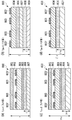
- 6A is a cross-sectional view showing a state in which a conventional flexible cable is fitted to a flexible cable connector
- FIG. 6B is a cross-sectional view taken along line VIB-VIB shown in FIG.
- FIG. 6C is a cross-sectional schematic view
- FIG. 6C is a cross-sectional view showing a state in which the flexible cable of the third embodiment of the present invention is fitted to the flexible cable connector
- FIG. FIG. 6C is a schematic cross-sectional view taken along the line VID-VID shown in FIG. 6C
- FIG. 6E shows a state where the flexible cable of the fourth embodiment of the present invention is fitted to the flexible cable connector
- FIG. 6 (f) is a schematic cross-sectional view along the line VIF-VIF shown in FIG. 6 (e).
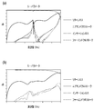
- FIG. 7A is a diagram illustrating the frequency characteristics of the transmission characteristics of the conventional flexible cable
- FIG. 7B is a diagram illustrating the frequency characteristics of the transmission characteristics of the flexible cable according to the third embodiment of the present invention.
- FIG. 7C is a diagram illustrating frequency characteristics of transmission characteristics of the flexible cable according to the fourth embodiment of the present invention.
- FIG. 8A is a schematic diagram showing a cross section of the flexible portion of Type A FPC
- FIG. 8B is a schematic diagram showing a cross section of the pad portion of the FPC shown in FIG.
- FIG. 8C is a schematic view showing a cross section of a flexible portion of Type B FPC
- FIG. 8D is a schematic view showing a cross section of a pad portion of the FPC shown in FIG. It is a figure which compares and shows the insertion loss of FPC of TypeA and TypeB.
- the concept of the vertical direction in the following description corresponds to the vertical direction in the attached drawings, and indicates the relative positional relationship of each member, and does not indicate the absolute positional relationship.
- the insertion direction of the connector is indicated as “front end”
- the opposite direction of the insertion direction of the connector is indicated as “rear end”
- the right and left direction is a direction orthogonal to the insertion direction of the connector. Indicates “left and right”, but does not indicate an absolute positional relationship.
- a flexible cable adapter 100 according to the first embodiment of the present invention is fixed by inserting a flexible cable 110 such as FPC or FFC.
- the flexible cable 110 is flexible.
- the cable connector 120 is detachably connected.
- the flexible cable adapter 100 includes a housing 101 formed of an insulating material and a high frequency characteristic improving unit 102 formed of a conductive resin.
- the housing 101 has a flat rectangular parallelepiped shape made of a synthetic resin molded product, and a housing recess 101d in which the high-frequency characteristic improving unit 102 is housed is formed at the bottom (the lower surface side shown in FIG. 2B). Yes.
- the housing recess 101d is a recess formed one step lower from the bottom of the housing 101 toward the upper direction, and has a downward cross-sectional shape having side wall portions 101e and 101e at both left and right ends. It is formed in a letter shape.
- the housing recess 101d has a bottom wall (upper wall in FIG. 2B) that is horizontally formed from the rear end (left end in FIG. 2B) to the front end (right end in FIG. 2B) of the housing 101.
- a vertical front wall portion 101f with which the tip of the high frequency characteristic improving portion 102 abuts is formed on the front end side.
- the depth of the housing recess 101d (the height of the front wall portion 101f) is formed to be substantially the same as the thickness of the high-frequency characteristic improving portion 102 and the flexible cable 110 superimposed. According to this, as shown in FIG. 2B, the bottom surface of the housing 101 and the bottom surface of the flexible cable 110 are flush with each other by housing the high frequency characteristic improving portion 102 and the flexible cable 110 in the housing recess 101d. It comes to become.
- An insertion portion 101b to be inserted into the flexible cable connector 120 is formed on the distal end side of the housing 101.
- the insertion portion 101b extends substantially horizontally from the distal end of the housing 101 (the right end in FIG. 2B) as the base end.
- An insulating resin portion 101g is provided at the distal end of the insertion portion 101b so that the distal end surface of the high frequency characteristic improving portion 102 is not exposed. According to this, since the tip of the conductive high-frequency characteristic improving unit 102 is covered with the insulating resin portion 101g, the high-frequency characteristic improving unit 102 is inserted when the flexible cable adapter 100 is inserted into and removed from the flexible cable connector 120. Can be prevented from contacting the contact terminal 121 and short-circuiting.
- lock portion 101c On both side surfaces of the housing 101, two lock portions 101c for engaging with two engagement portions 122b described later of the flexible cable connector 120 are formed.
- the lock portion 101c is made of an elastically deformable locking piece, and the lock portion 101c is elastically engaged with the engagement portion 122b of the flexible cable connector 120.
- the conductive resin that forms the high-frequency characteristic improving portion 102 by filling an inorganic conductive material with an intrinsic conductive resin having conductivity derived from the structure of the original polymer and a non-conductive resin, A composite conductive polymer that exhibits conductivity is known, but is not particularly limited.
- the conductivity of the conductive resin forming the high-frequency characteristic improving unit 102 and the distance between the high-frequency characteristic improving unit 102 and a plurality of conductors 111 to be described later are transmitted and received signals in a high-frequency band. This point needs attention because it affects the characteristics.
- the flexible cable 110 includes a plurality of conductors 111, a plurality of conductors 111 aligned and fixed, and insulated and held from each other, such as LCP (Liquid Crystal Crystal) or polyimide.
- a base 112 made of an insulating material, and a pad 113 formed on both ends of the base 112 and arranged to fix a plurality of conductors 111 exposed on the surface for electrical contact with the outside Prepare for.
- the flexible cable 110 is fixed in a state of being integrally bonded together with the high-frequency characteristic improving unit 102 by heat fusion.
- the fixing method of the flexible cable 110 and the high frequency characteristic improvement part 102 is not limited to the method shown by this embodiment.
- the flexible cable connector 120 is in electrical contact with the exposed plurality of conductors 111 of the pad portion 113, and a land of a circuit board (not shown).
- a plurality of contact terminals 121 connected to the pattern by soldering or the like, a connector housing 122 that aligns and fixes the plurality of contact terminals 121 and insulates and holds them, and is arranged on both side surfaces of the connector housing 122;
- the flexible cable connector 120 is fixed to a circuit board, and mainly includes two fixing brackets 123 formed of a metal material.
- the connector housing 122 is formed of an insulating material, and an opening 122 a into which the insertion portion 101 b of the housing 101 of the flexible cable adapter 100 is inserted is formed on the rear end side of the connector housing 122. Further, two engaging portions 122b for engaging the lock portion 101c of the housing 101 of the flexible cable adapter 100 are formed on both side surfaces inside the opening portion 122a.
- the flexible cable 110 inserted and fixed in the opening 101a of the housing 101 of the flexible cable adapter 100 reaches the vicinity of the insertion portion 101b on the distal end side, and FIG.
- the plurality of conductors 111 disposed on the pad portion 113 of the flexible cable 110 are exposed on the lower surface side shown in FIG.
- the plurality of conductors 111 exposed on the lower surface side come into contact with the plurality of contact terminals 121 of the flexible cable connector 120 and are electrically connected in the fitting state shown in FIG.
- the high-frequency characteristic improving portion 102 formed of the conductive resin of the flexible cable adapter 100 is the upper surface of the pad portion 113 shown in FIG. It is arranged so as to cover the side.
- the high frequency characteristic improving unit 102 is formed of the plurality of conductors 111 of the flexible cable 110 and an insulating material.
- the separated base material 112 is separated.
- FIG. 3 (a) it can be seen that in the conventional flexible cable adapter that does not include the high-frequency characteristic improving portion 102 formed of a conductive resin, an insertion loss ripple occurs in a predetermined band. Similarly, it can be seen that a large waveform disturbance occurs in a predetermined band for return loss, far-end crosstalk, and near-end crosstalk. In such a case, there is a possibility that the characteristic impedance is not matched, the transmission characteristic is deteriorated, and the signal cannot be transmitted / received.
- any of insertion loss, return loss, far-end crosstalk, and near-end crosstalk is selected. Also, it can be seen that there is no significant waveform disturbance such as ripple, and the transmission characteristics do not deteriorate.
- the FPC 300 includes a plurality of conductors 301 from above. , LCP layer 302, adhesive layer 303, and reinforcing plate layer 304, and FPC On the outside of the reinforcing plate layer 304 of 300, a high frequency characteristic improving portion 102 made of a conductive resin of the flexible cable adapter 100 is disposed.
- FPC was used here as the flexible cable 110, it is good also as what uses FFC.
- the high frequency characteristic improving portion 102 formed of a conductive resin is arranged at a certain distance from the plurality of conductors 111.
- this distance varies depending on the conductivity of the conductive resin and the frequency of signals transmitted and received.
- the transmission characteristics in the high frequency band are improved by separating the combined distance of the LCP layer 302, the adhesive layer 303, and the reinforcing plate layer 304 used as the insulating material of the FPC 300.
- the matching of the characteristic impedance between the pad portion of the flexible cable and the contact terminal of the connector in the high frequency band is improved, and reflection is improved. It is possible to suppress the occurrence of return loss and insertion loss.
- the flexible cable connector 400 according to the second embodiment of the present invention is connected to the flexible cable 110 so that it can be inserted and removed.
- the flexible cable connector 400 is disposed so as to cover a plurality of contact terminals 401, a base side housing 402 that holds the plurality of contact terminals 401, and an upper surface of the base side housing 402.
- a cover side housing 403, an insulating tape 404 affixed to the back side of the cover side housing 403, a base side housing 402 and a cover side housing 403 are bonded together and fixed to a circuit board (not shown).
- two fixing brackets 405 made of metal.
- the plurality of contact terminals 401 are formed of copper on a metal material such as gold plating, and are electrically connected to the plurality of exposed conductors 111 of the pad portion 113 of the flexible cable 110 to form a land pattern on a circuit board (not shown). Connected by soldering.
- the base-side housing 402 is a molded product of an insulating material and is formed in a horizontally long flat shape, and is cut out in an L-shaped cross section from the upper surface to the front surface.
- a plurality of contact terminals 401 are aligned and fixed to a horizontal bottom portion 406a of the notch portion 406 of the base side housing 402 while being insulated from each other.
- Base-side fixing grooves 402 a into which fixing brackets 405 described later are inserted are formed on both left and right ends of the base-side housing 402.
- the cover-side housing 403 is made of a conductive resin that functions as a high-frequency characteristic improving portion, and is formed in a horizontally long flat plate shape that is substantially the same as the base-side housing 402.
- a cover-side fixing groove 403a into which a later-described fixing metal fitting 405 is inserted is formed at a position on the same line as the base-side fixing groove 402a.
- the base side housing 402 and the cover side housing 403 are combined so that the cover side housing 403 is positioned on the base side housing 402, whereby the base side fixing groove 402a and the cover side fixing groove 403a Communicate with each other on the same line, and two fixing brackets 405 can be press-fitted and fixed to each side.
- an opening 400a into which the flexible cable 110 is inserted is formed on the rear end side of the flexible cable connector 400 (the left end in FIG. 4D).
- the two fixing metal fittings 405 are press-fitted and fixed to both side surfaces, but the present invention is not limited to this, and other fixing methods such as an adhesive may be used.
- the base side housing 402 and the cover side housing 403 may be integrally formed by two-color molding.
- the insulating tape 404 is a sheet made of an insulating material and is attached to the back surface of the cover side housing 403 on the opening 400a side. Accordingly, it is possible to prevent the plurality of contact terminals 401 and the cover-side housing 403 formed of a conductive resin from being in electrical contact with each other. If there is no possibility of contact between the plurality of contact terminals 401 and the cover-side housing 403 formed of a conductive resin, there is no need to affix the insulating tape 404.
- the back surface of the cover-side housing 403 is formed with a reverse V-shaped notch portion from both ends in the width direction (left-right direction in FIG. And a cover-side housing 403 may be provided to prevent a short circuit.
- an insertion loss ripple occurs in a predetermined band.
- a large waveform disturbance occurs in a predetermined band for return loss, far-end crosstalk, and near-end crosstalk.
- characteristic impedance is not matched, transmission performance is deteriorated, and signals cannot be transmitted and received.
- any of insertion loss, return loss, far-end crosstalk, and near-end crosstalk is selected. Also, it can be seen that there is no significant waveform disturbance such as ripples, and the transmission performance does not deteriorate.
- the cover-side housing 403 that functions as a high-frequency characteristic improving unit, and the pads of the flexible cable 110
- the plurality of conductors 111 arranged in the portion 113 are separated from each other by the base material 112 formed of an insulating material, and the same effect as that of the first embodiment can be obtained.
- a conventional flexible cable connector 620 aligns and fixes a plurality of contact terminals 621 and the plurality of contact terminals 621, and insulates and holds them. It mainly includes a connector housing 622 and two fixing brackets 405 that are arranged on both side surfaces of the connector housing 622 and fix the flexible cable connector 620 to the circuit board.
- the connector housing 622 is formed of an insulating material, and an opening 622a into which, for example, the FPC 300 is inserted as the flexible cable 110 is formed on the rear end side of the connector housing 622.
- the conventional FPC 300 is inserted into the opening 622a of the flexible cable connector 620.
- FIG. The plurality of conductors 301 exposed on the surface of the pad portion of the FPC 300 appear on the lower surface side shown in FIG. 6A and are in contact with the plurality of contact terminals 621.
- the surface of the pad portion of the FPC 300 opposite to the exposed plurality of conductors 301 is in contact with the upper surface side of the connector housing 622 of the opening 622a of the flexible cable connector 620.
- FIG. 6B The schematic diagram shown in FIG. 6B is shown upside down from the diagram shown in FIG. 6A for convenience of explanation.
- a conventional FPC 300 is composed of a plurality of conductors 301, an LCP layer 302, an adhesive layer 303, and a reinforcing plate layer 304 from the top.
- the outer side of the reinforcing plate layer 304 is the connector housing 622. It is in contact with the upper surface.
- the flexible cable 600 according to the third embodiment of the present invention is obtained by adding a conductive filler to the adhesive layer 603, as compared with the conventional FPC 300, and generating a high frequency signal. It functions differently as a characteristic improvement unit, and the other configurations are the same. The same components are denoted by the same reference numerals and description thereof is omitted.
- the adhesive layer 603 of the flexible cable 600 of this embodiment shall add a conductive filler, it is not limited to this, It is good also as what is equipped with electroconductivity by another method, and electroconductivity. What is necessary is just to function as a high frequency characteristic improvement part formed with resin.
- the flexible cable 610 of the 4th Embodiment of this invention uses a conductive resin sheet for the reinforcement board layer 614, It functions differently as a high-frequency characteristic improving unit, and the other configurations are the same.
- the same components are denoted by the same reference numerals and description thereof is omitted.
- the reinforcing plate layer 614 of the flexible cable 610 of the present embodiment uses a conductive resin sheet, but is not limited thereto, and may be provided with conductivity by other methods. What is necessary is just to function as a high frequency characteristic improvement part formed with the property resin.
- FIG. 7A it can be seen that in the conventional FPC 300 that does not include the high-frequency characteristic improving portion formed of a conductive resin, an insertion loss ripple occurs in a predetermined band. Similarly, it can be seen that a large waveform disturbance occurs in a predetermined band for return loss, far-end crosstalk, and near-end crosstalk. As in the first and second embodiments, in such a case, there is a possibility that characteristic impedance is not matched, transmission performance is deteriorated, and signals cannot be transmitted and received.
- the waveform loss such as the occurrence of ripple does not occur in any of the transmission loss, return loss, far-end crosstalk, and near-end crosstalk, and the transmission performance does not deteriorate.
- the adhesive layer that functions as a high-frequency characteristic improving unit. 603 or the reinforcing plate layer 614 and the plurality of conductors 301 arranged in the pad portion of the flexible cable are separated by the LCP layer 302 formed of an insulating material. The same effect as that of the second embodiment can be obtained.
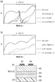
- the flexible portion of the Type A FPC 800 includes a coverlay polyimide layer 801, a low-loss adhesive layer 802, a plurality of conductors 803, an LCP layer 804, a GND layer 805, a coverlay adhesive layer 806, from above. And a cover lay polyimide layer 807.
- the configuration in which the signal line conductor 803 is surrounded by the GND line conductor 803 ′ disposed on both sides of the signal line conductor 803 and the GND layer 805, which is the second conductor layer, is called a microstrip line. It is a configuration that suppresses radiation and has excellent transmission characteristics at high frequencies.
- the pad portion of the Type A FPC 800 has the coverlay polyimide layer 801 and the low-loss adhesive layer 802 removed from the flexible portion shown in FIG.
- An agent layer 808 and a reinforcing plate layer 809 are added.
- the flexible portion of the Type B FPC 810 has the same configuration as the Type A FPC 800, but the combined thickness of the coverlay adhesive layer 816 and the coverlay polyimide layer 817 is thicker by ⁇ . It is different that it is configured to be. Similar components are denoted by the same reference numerals, and description thereof is omitted.
- the pad portion of the Type B FPC 810 has the cover lay polyimide layer 801 and the low-loss adhesive layer 802 removed from the flexible portion, but the Type A FPC 800 shown in FIG. Unlike the pad portion, an adhesive layer and a reinforcing plate layer are not added. Therefore, when comparing the thickness Z of the pad portion of the Type A FPC 800 with the thickness Z ′ + ⁇ of the pad portion of the Type B FPC 810, the thickness Z of the pad portion of the Type A FPC 800 is slightly thicker. It is configured.
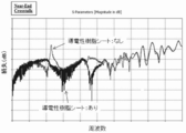
- FIG. 9 is a diagram showing a comparison of insertion loss of Type A and Type B FPCs.
- the Type B FPC 810 having a smaller thickness has a lower value.
- the characteristics of the high frequency band can be further improved if the thickness of the FPC is selected in consideration of these points.
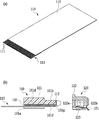
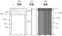
- the flexible cable 500 has a flexible cable main body 510 (hereinafter simply referred to as an FPC main body 510) having a pad portion P at one end on the front surface side (the upper end in FIG. 10A), and the rear surface of the FPC main body 510 (see FIG. 10).
- a conductive resin sheet 530 is provided as a high-frequency characteristic improving portion so as to cover the pad portion P.
- the FPC main body 510 has a straight belt shape, but may be, for example, an L shape or a crank shape.
- the pad portion P is provided so as to be exposed on the front surface side of the FPC main body 510, but may be provided on the rear surface side of the FPC main body 510, or may be provided on both the front surface side and the rear surface side. It may be.
- the pad portion P may be provided not only at the front end or the rear end but also at the side end, and can be changed to any position according to the specifications of the connector to be connected.
- the FPC main body 510 includes a base material 511 made of an insulating resin sheet, and coverlays 513 and 514 arranged on both surfaces of the base material 511.
- a conductor 512 is disposed on the lower surface in the embodiment.
- the conductor 512 is a metal foil formed with a predetermined circuit pattern, and a pad portion P is formed by exposing a part of the conductor 512 to the surface.
- the coverlays 513 and 514 are optional components and are considered to be substantially the same as the structure shown in FIG.
- the FPC main body 510 can omit the coverlay 514 on the back surface side, but if it is omitted, the conductive resin sheet 530 needs to be bonded to the entire back surface of the FPC main body and insulated from the back surface of the base material 511. is there.
- a conductive resin sheet 530 is provided on the back side facing the pad portion P of the FPC main body 510.
- the conductive resin sheet 530 has a predetermined layer thickness (preferably a layer thickness of 0.1 ⁇ m) on the surface (upper surface in FIG. 10) of the base sheet 531 made of synthetic resin. The conductive resin sheet formed in the above is used.
- the conductive resin sheet 530 is most preferably an organic conductive material having good environmental resistance (heat resistance and chemical resistance), but other conductive materials are used regardless of organic or inorganic. May be used. That is, it may be a resin sheet containing a conductive filler such as carbon, a metal deposition film sheet, a carbon nanotube (CNT) coating sheet, or the like.
- a conductive filler such as carbon, a metal deposition film sheet, a carbon nanotube (CNT) coating sheet, or the like.
- the conductive polymer layer 532 is disposed opposite to the back surface side facing the pad portion P of the FPC main body 510.
- the conductive resin sheet 530 is arranged in an area larger than the area of the pad portion P.
- the size thereof depends on the specification. It can be changed arbitrarily.
- an adhesive layer 520 for attaching the conductive resin sheet 530 is provided between the back side of the FPC main body 510 and the conductive polymer layer 532.
- the pressure-sensitive adhesive layer 520 may be provided on either the back side of the FPC main body 510 or the surface of the conductive polymer layer 532 of the conductive resin sheet 530.
- the conductive resin sheet 530 is compared. It has been found that the flexible cable having impedance can achieve impedance matching and reduce insertion loss.
- the high frequency characteristic is improved by integrally bonding the conductive resin sheet 530 having the organic conductive polymer layer 532 formed on the back surface side facing the pad portion P of the FPC main body 510. Can do.
- the matching of the characteristic impedance between the pad portion of the flexible cable and the contact terminal of the connector in the high frequency band is improved.
- the reflection can be suppressed and the occurrence of return loss and insertion loss can be reduced.
Landscapes
- Coupling Device And Connection With Printed Circuit (AREA)
- Details Of Connecting Devices For Male And Female Coupling (AREA)
Abstract
Description
300の補強板層304の外側にはフレキシブルケーブル用アダプタ100の導電性樹脂で形成された高周波特性改善部102が配置される。なお、ここでは、フレキシブルケーブル110として、FPCを使用したが、FFCを使用するものとしてもよい。
101 ハウジング
101a、122a、400a、622a 開口部
101b 挿入部
101c ロック部
101d 収納凹部
101e 側壁部
101f 前壁部
101g 絶縁樹脂部
102 高周波特性改善部
110、600、610、500 フレキシブルケーブル
111、301、803、803´ 導体
112 基材
113 パッド部
120、400、620 フレキシブルケーブル用コネクタ
121、401、621 コンタクト端子
122、622 コネクタハウジング
122b 係合部
123、405 固定金具
300、800、810 FPC
302、804 LCP層
303、603、808 接着剤層
304、614、809 補強板層
402 ベース側ハウジング
402a ベース側固定溝
403 カバー側ハウジング
403a ベース側固定溝
404 絶縁テープ
406 切欠部
406a 底部
510 FPC本体
520 接着剤層
530 導電性樹脂シート
531 ベースシート
532 導電性高分子層
801、807、817 カバーレイポリイミド層
802 低損失接着剤層
805 GND層
806、816 カバーレイ接着剤層
Claims (11)
- フレキシブルケーブルとフレキシブルケーブル用コネクタとの接続構造であって、前記フレキシブルケーブルは、複数の導体と、前記複数の導体を整列して固定し、互いに絶縁して保持する、屈曲率が高く薄い絶縁材料で形成された基材と、前記基材の両端に形成され、前記フレキシブルケーブル用コネクタの複数のコンタクト端子と電気的に接触させるために表面に露出された前記複数の導体を整列して固定するパッド部とを備え、
前記フレキシブルケーブル、あるいは、前記フレキシブルケーブル用コネクタの周囲に配置された導電性樹脂で形成された高周波特性改善部を更に備え、前記高周波特性改善部と、前記フレキシブルケーブルの前記パッド部に配置された前記複数の導体との間が、前記絶縁材料で形成された前記基材により離間されることを特徴とするフレキシブルケーブルとフレキシブルケーブル用コネクタとの接続構造。 - フレキシブルケーブルが挿入されて固定され、前記フレキシブルケーブルをフレキシブルケーブル用コネクタに挿抜可能に接続するためのフレキシブルケーブル用アダプタであって、
絶縁材料で形成され、前記フレキシブルケーブルが挿入されて固定される開口部を有するハウジングと、前記ハウジングの前記開口部の周囲であって、前記フレキシブルケーブルのパッド部の露出された複数の導体が配置される面とは反対側の面に配置される導電性樹脂で形成された高周波特性改善部とを備えることを特徴とするフレキシブルケーブル用アダプタ。 - 前記高周波特性改善部の先端側は、前記ハウジングによって覆われ、前記フレキシブルケーブル用アダプタを前記フレキシブルケーブル用コネクタに挿入する際、前記高周波特性改善部と前記フレキシブルケーブル用コネクタの複数のコンタクト端子とが前記ハウジングによって電気的に非接触となることを特徴とする請求項2に記載のフレキシブルケーブル用アダプタ。
- フレキシブルケーブルが挿抜可能に接続される開口部を有するフレキシブルケーブル用コネクタであって、前記フレキシブルケーブルのパッド部の露出された複数の導体に接触するための複数のコンタクト端子と、前記複数のコンタクト端子を整列して固定し、互いに絶縁して保持するベース側ハウジングと、前記ベース側ハウジングの上面を覆うように配置され、導電性樹脂で形成された高周波特性改善部であるカバー側ハウジングとを備えることを特徴とするフレキシブルケーブル用コネクタ。
- 前記ベース側ハウジングと、前記カバー側ハウジングは、2色成型により一体に成型されることを特徴とする請求項4に記載のフレキシブルケーブル用コネクタ。
- 前記フレキシブルケーブル用コネクタの前記カバー側ハウジングの前記開口部側の裏面に、前記複数のコンタクト端子との電気的接触を防止する絶縁部材が設けられることを特徴とする請求項4に記載のフレキシブルケーブル用コネクタ。
- フレキシブルケーブル用コネクタの開口部に挿抜可能に接続されるフレキシブルケーブルであって、
複数の導体を保持する基材と、前記フレキシブルケーブル用コネクタの複数のコンタクト端子に電気的に接触させるために、前記複数の導体の一部を前記基材の表面に露出してなるパッド部と、前記基材の前記パッド部に対向する裏面側に配置される高周波特性改善部と、を備えることを特徴とするフレキシブルケーブル。 - 前記高周波特性改善部は、導電性フィラーが添加された導電性接着剤層であり、前記導電性接着剤層を介して所定の補強板が貼着されることを特徴とする請求項7に記載のフレキシブルケーブル。
- 前記高周波特性改善部は導電性樹脂シートからなり、前記導電性樹脂シートが、前記基材の前記パッド部に対向する裏面側に貼着されていることを特徴とする請求項7に記載のフレキシブルケーブル。
- 前記導電性樹脂シートは、ベースシートの表面に有機導電性高分子層が所定の層厚で形成され、前記導電性高分子層が前記基材の裏面に対向するように配置されていることを特徴とする請求項9に記載のフレキシブルケーブル。
- 前記基材の裏面と前記導電性高分子層との間には、前記導電性樹脂シートを貼着するための粘着剤層が設けられていることを特徴とする請求項10に記載のフレキシブルケーブル。
Priority Applications (3)
| Application Number | Priority Date | Filing Date | Title |
|---|---|---|---|
| JP2018536949A JP6721845B2 (ja) | 2016-08-30 | 2017-06-02 | フレキシブルケーブル用コネクタ、フレキシブルケーブル用アダプタ、及び、フレキシブルケーブル |
| EP17845804.8A EP3509167A4 (en) | 2016-08-30 | 2017-06-02 | FLEXIBLE CABLE CONNECTOR, FLEXIBLE CABLE ADAPTER AND FLEXIBLE CABLE |
| CN201780035041.6A CN109314351B (zh) | 2016-08-30 | 2017-06-02 | 挠性线缆用连接器、挠性线缆用适配器以及挠性线缆 |
Applications Claiming Priority (2)
| Application Number | Priority Date | Filing Date | Title |
|---|---|---|---|
| JP2016168058 | 2016-08-30 | ||
| JP2016-168058 | 2016-08-30 |
Publications (1)
| Publication Number | Publication Date |
|---|---|
| WO2018042793A1 true WO2018042793A1 (ja) | 2018-03-08 |
Family
ID=61300381
Family Applications (1)
| Application Number | Title | Priority Date | Filing Date |
|---|---|---|---|
| PCT/JP2017/020593 Ceased WO2018042793A1 (ja) | 2016-08-30 | 2017-06-02 | フレキシブルケーブル用コネクタ、フレキシブルケーブル用アダプタ、及び、フレキシブルケーブル |
Country Status (4)
| Country | Link |
|---|---|
| EP (1) | EP3509167A4 (ja) |
| JP (1) | JP6721845B2 (ja) |
| CN (1) | CN109314351B (ja) |
| WO (1) | WO2018042793A1 (ja) |
Cited By (5)
| Publication number | Priority date | Publication date | Assignee | Title |
|---|---|---|---|---|
| CN109494502A (zh) * | 2018-11-23 | 2019-03-19 | 合肥联宝信息技术有限公司 | 一种柔性电缆连接器及电子设备 |
| CN109936031A (zh) * | 2018-10-19 | 2019-06-25 | 王小敏 | Fpc排线结构及其包胶成型方式 |
| US20220115800A1 (en) * | 2020-10-08 | 2022-04-14 | Samsung Electronics Co, Ltd. | Electronic device including host connector and memory device |
| US20240322469A1 (en) * | 2023-03-20 | 2024-09-26 | J.S.T. Mfg. Co., Ltd. | Connector |
| US12213244B2 (en) | 2021-11-01 | 2025-01-28 | Canon Kabushiki Kaisha | Transmission module, electronic unit, and electronic device |
Families Citing this family (3)
| Publication number | Priority date | Publication date | Assignee | Title |
|---|---|---|---|---|
| CN116569498B (zh) * | 2020-07-15 | 2025-02-14 | 赛峰乘客创新有限公司 | 用于移动平台的柔性多调制解调器宽带终端 |
| CN116053829A (zh) * | 2021-10-28 | 2023-05-02 | 上海海思技术有限公司 | 一种排线连接器及电子设备 |
| JP7633533B2 (ja) * | 2022-06-14 | 2025-02-20 | 山一電機株式会社 | 高周波信号伝送装置、及び配線基板とコネクタの電気的接続方法 |
Citations (8)
| Publication number | Priority date | Publication date | Assignee | Title |
|---|---|---|---|---|
| JPH0613122A (ja) * | 1992-04-24 | 1994-01-21 | Fujikura Ltd | ケーブルの端末構造 |
| JP2002216873A (ja) | 2001-01-23 | 2002-08-02 | Pfu Ltd | ケーブルのシールド接続構造 |
| JP2007109420A (ja) * | 2005-10-11 | 2007-04-26 | Taiko Denki Co Ltd | シールド付きコネクタ |
| JP2008218252A (ja) * | 2007-03-06 | 2008-09-18 | Auto Network Gijutsu Kenkyusho:Kk | フレキシブルフラットケーブル |
| JP2008251485A (ja) * | 2007-03-30 | 2008-10-16 | Fujitsu Component Ltd | コネクタ装置 |
| JP2008300129A (ja) * | 2007-05-30 | 2008-12-11 | Yazaki Corp | コネクタ、レセプタクル、スライダ |
| JP2008545249A (ja) * | 2005-06-30 | 2008-12-11 | アムフェノール・コーポレーション | 合わさり接点領域内の遮蔽効果が改良されたコネクタ |
| JP2009272256A (ja) | 2008-05-09 | 2009-11-19 | Tyco Electronics Amp Kk | 電気コネクタ |
Family Cites Families (13)
| Publication number | Priority date | Publication date | Assignee | Title |
|---|---|---|---|---|
| JPS6114476U (ja) * | 1984-06-29 | 1986-01-28 | 株式会社フジクラ | 通信ケ−ブルとコネクタとの接続構造 |
| JPH08279667A (ja) * | 1995-04-06 | 1996-10-22 | Murata Mfg Co Ltd | フレキシブル基板 |
| JP4152019B2 (ja) * | 1998-09-30 | 2008-09-17 | 日本圧着端子製造株式会社 | 多極同軸コネクタ |
| JP2001068907A (ja) * | 1999-08-26 | 2001-03-16 | Yamaichi Electronics Co Ltd | Fpcケーブルおよびfpcケーブル用コネクタ |
| JP4526115B2 (ja) * | 2004-05-24 | 2010-08-18 | ソニーケミカル&インフォメーションデバイス株式会社 | フレキシブルフラットケーブル |
| JP4407471B2 (ja) * | 2004-10-29 | 2010-02-03 | パナソニック株式会社 | フレキシブル配線基板とそれを用いた電子機器およびその製造方法 |
| JP5100114B2 (ja) * | 2006-12-28 | 2012-12-19 | 日本圧着端子製造株式会社 | Fpc接続用コネクタ |
| JP5029965B2 (ja) * | 2007-06-29 | 2012-09-19 | 山一電機株式会社 | ケーブル・コネクタ用アダプタ |
| JP5335080B2 (ja) * | 2009-06-01 | 2013-11-06 | 東京特殊電線株式会社 | シールド層付フレキシブルフラットケーブル |
| JP2011159880A (ja) * | 2010-02-02 | 2011-08-18 | Sumitomo Electric Printed Circuit Inc | 差込端付フレキシブルプリント配線板、フレキシブルプリント配線板の接続構造、および電子機器 |
| JP5019079B2 (ja) * | 2010-03-10 | 2012-09-05 | 第一精工株式会社 | コネクタ装置 |
| CN104247158B (zh) * | 2012-03-30 | 2017-03-15 | 莫列斯公司 | 连接器 |
| CN102629723B (zh) * | 2012-04-24 | 2014-10-22 | 东莞宇球电子股份有限公司 | 扁平式导体用电连接器 |
-
2017
- 2017-06-02 WO PCT/JP2017/020593 patent/WO2018042793A1/ja not_active Ceased
- 2017-06-02 CN CN201780035041.6A patent/CN109314351B/zh active Active
- 2017-06-02 JP JP2018536949A patent/JP6721845B2/ja active Active
- 2017-06-02 EP EP17845804.8A patent/EP3509167A4/en not_active Withdrawn
Patent Citations (8)
| Publication number | Priority date | Publication date | Assignee | Title |
|---|---|---|---|---|
| JPH0613122A (ja) * | 1992-04-24 | 1994-01-21 | Fujikura Ltd | ケーブルの端末構造 |
| JP2002216873A (ja) | 2001-01-23 | 2002-08-02 | Pfu Ltd | ケーブルのシールド接続構造 |
| JP2008545249A (ja) * | 2005-06-30 | 2008-12-11 | アムフェノール・コーポレーション | 合わさり接点領域内の遮蔽効果が改良されたコネクタ |
| JP2007109420A (ja) * | 2005-10-11 | 2007-04-26 | Taiko Denki Co Ltd | シールド付きコネクタ |
| JP2008218252A (ja) * | 2007-03-06 | 2008-09-18 | Auto Network Gijutsu Kenkyusho:Kk | フレキシブルフラットケーブル |
| JP2008251485A (ja) * | 2007-03-30 | 2008-10-16 | Fujitsu Component Ltd | コネクタ装置 |
| JP2008300129A (ja) * | 2007-05-30 | 2008-12-11 | Yazaki Corp | コネクタ、レセプタクル、スライダ |
| JP2009272256A (ja) | 2008-05-09 | 2009-11-19 | Tyco Electronics Amp Kk | 電気コネクタ |
Non-Patent Citations (1)
| Title |
|---|
| See also references of EP3509167A4 * |
Cited By (7)
| Publication number | Priority date | Publication date | Assignee | Title |
|---|---|---|---|---|
| CN109936031A (zh) * | 2018-10-19 | 2019-06-25 | 王小敏 | Fpc排线结构及其包胶成型方式 |
| CN109494502A (zh) * | 2018-11-23 | 2019-03-19 | 合肥联宝信息技术有限公司 | 一种柔性电缆连接器及电子设备 |
| CN109494502B (zh) * | 2018-11-23 | 2024-04-23 | 合肥联宝信息技术有限公司 | 一种柔性电缆连接器及电子设备 |
| US20220115800A1 (en) * | 2020-10-08 | 2022-04-14 | Samsung Electronics Co, Ltd. | Electronic device including host connector and memory device |
| US11791579B2 (en) * | 2020-10-08 | 2023-10-17 | Samsung Electronics Co., Ltd. | Electronic device including host connector and memory device |
| US12213244B2 (en) | 2021-11-01 | 2025-01-28 | Canon Kabushiki Kaisha | Transmission module, electronic unit, and electronic device |
| US20240322469A1 (en) * | 2023-03-20 | 2024-09-26 | J.S.T. Mfg. Co., Ltd. | Connector |
Also Published As
| Publication number | Publication date |
|---|---|
| JPWO2018042793A1 (ja) | 2019-03-28 |
| EP3509167A4 (en) | 2020-03-25 |
| CN109314351B (zh) | 2021-04-02 |
| EP3509167A1 (en) | 2019-07-10 |
| JP6721845B2 (ja) | 2020-07-15 |
| CN109314351A (zh) | 2019-02-05 |
Similar Documents
| Publication | Publication Date | Title |
|---|---|---|
| JP6721845B2 (ja) | フレキシブルケーブル用コネクタ、フレキシブルケーブル用アダプタ、及び、フレキシブルケーブル | |
| US11011874B2 (en) | Connector and connector assembly | |
| US11715582B2 (en) | Shielded flat cable | |
| US12272904B2 (en) | Electrical connector with shielding between low and high frequency terminals and electrical connector device using the same | |
| JP5527840B2 (ja) | 挿入位置決め構造を有する回路配線 | |
| US11424579B2 (en) | Connector and connector device | |
| JPH09139610A (ja) | マイクロストリップフレキシブル基板接続ライン | |
| JP2007234500A (ja) | 高速伝送用fpc及びこのfpcに接続されるプリント基板 | |
| JPWO2020130010A1 (ja) | 伝送線路部材 | |
| US20210020329A1 (en) | Flexible cable | |
| KR20200101006A (ko) | 플렉서블 평판 케이블 및 그 제조방법 | |
| KR20230000588A (ko) | 리셉터클 커넥터와 플러그 커넥터를 포함하는 커넥터 조립체 및 플러그 커넥터 | |
| JPWO2004093036A1 (ja) | 薄型表示装置及びプラズマディスプレイ | |
| JP2011150848A (ja) | シールド構造を備えたコネクタ | |
| US20220384998A1 (en) | Shielded flat cable and shielded flat cable with circuit board | |
| WO2020121984A1 (ja) | 電子機器、および、フラットケーブル | |
| JP5938342B2 (ja) | シート付コネクタ | |
| JP2010016076A (ja) | フレキシブルプリント基板及びこれを備えたリジッドフレキシブルプリント基板 | |
| JP2011077004A (ja) | コネクタ | |
| US20250062574A1 (en) | Electrical-connector-equipper cable | |
| US20250062556A1 (en) | Electrical-connector-equipped flat cable | |
| CN109887649B (zh) | 可挠式高频连接线、高频连接电路板组合及电连接器组合 | |
| JP2001035612A (ja) | Fpc/ffcコネクタ | |
| CN117136419A (zh) | 高频信号传送装置以及高频信号传送线缆 | |
| TWM437563U (en) | Electrical connector |
Legal Events
| Date | Code | Title | Description |
|---|---|---|---|
| ENP | Entry into the national phase |
Ref document number: 2018536949 Country of ref document: JP Kind code of ref document: A |
|
| 121 | Ep: the epo has been informed by wipo that ep was designated in this application |
Ref document number: 17845804 Country of ref document: EP Kind code of ref document: A1 |
|
| NENP | Non-entry into the national phase |
Ref country code: DE |
|
| ENP | Entry into the national phase |
Ref document number: 2017845804 Country of ref document: EP Effective date: 20190401 |
|
| WWW | Wipo information: withdrawn in national office |
Ref document number: 2017845804 Country of ref document: EP |