WO2018042941A1 - 誘導加熱調理器 - Google Patents
誘導加熱調理器 Download PDFInfo
- Publication number
- WO2018042941A1 WO2018042941A1 PCT/JP2017/026623 JP2017026623W WO2018042941A1 WO 2018042941 A1 WO2018042941 A1 WO 2018042941A1 JP 2017026623 W JP2017026623 W JP 2017026623W WO 2018042941 A1 WO2018042941 A1 WO 2018042941A1
- Authority
- WO
- WIPO (PCT)
- Prior art keywords
- heating coil
- heating
- coils
- unit
- turned
- Prior art date
- Legal status (The legal status is an assumption and is not a legal conclusion. Google has not performed a legal analysis and makes no representation as to the accuracy of the status listed.)
- Ceased
Links
Images


Classifications
-
- H—ELECTRICITY
- H05—ELECTRIC TECHNIQUES NOT OTHERWISE PROVIDED FOR
- H05B—ELECTRIC HEATING; ELECTRIC LIGHT SOURCES NOT OTHERWISE PROVIDED FOR; CIRCUIT ARRANGEMENTS FOR ELECTRIC LIGHT SOURCES, IN GENERAL
- H05B6/00—Heating by electric, magnetic or electromagnetic fields
- H05B6/02—Induction heating
- H05B6/10—Induction heating apparatus, other than furnaces, for specific applications
- H05B6/12—Cooking devices
- H05B6/1209—Cooking devices induction cooking plates or the like and devices to be used in combination with them
- H05B6/1245—Cooking devices induction cooking plates or the like and devices to be used in combination with them with special coil arrangements
- H05B6/1272—Cooking devices induction cooking plates or the like and devices to be used in combination with them with special coil arrangements with more than one coil or coil segment per heating zone
-
- H—ELECTRICITY
- H05—ELECTRIC TECHNIQUES NOT OTHERWISE PROVIDED FOR
- H05B—ELECTRIC HEATING; ELECTRIC LIGHT SOURCES NOT OTHERWISE PROVIDED FOR; CIRCUIT ARRANGEMENTS FOR ELECTRIC LIGHT SOURCES, IN GENERAL
- H05B6/00—Heating by electric, magnetic or electromagnetic fields
- H05B6/02—Induction heating
- H05B6/06—Control, e.g. of temperature, of power
- H05B6/062—Control, e.g. of temperature, of power for cooking plates or the like
-
- H—ELECTRICITY
- H05—ELECTRIC TECHNIQUES NOT OTHERWISE PROVIDED FOR
- H05B—ELECTRIC HEATING; ELECTRIC LIGHT SOURCES NOT OTHERWISE PROVIDED FOR; CIRCUIT ARRANGEMENTS FOR ELECTRIC LIGHT SOURCES, IN GENERAL
- H05B2213/00—Aspects relating both to resistive heating and to induction heating, covered by H05B3/00 and H05B6/00
- H05B2213/07—Heating plates with temperature control means
-
- Y—GENERAL TAGGING OF NEW TECHNOLOGICAL DEVELOPMENTS; GENERAL TAGGING OF CROSS-SECTIONAL TECHNOLOGIES SPANNING OVER SEVERAL SECTIONS OF THE IPC; TECHNICAL SUBJECTS COVERED BY FORMER USPC CROSS-REFERENCE ART COLLECTIONS [XRACs] AND DIGESTS
- Y02—TECHNOLOGIES OR APPLICATIONS FOR MITIGATION OR ADAPTATION AGAINST CLIMATE CHANGE
- Y02B—CLIMATE CHANGE MITIGATION TECHNOLOGIES RELATED TO BUILDINGS, e.g. HOUSING, HOUSE APPLIANCES OR RELATED END-USER APPLICATIONS
- Y02B40/00—Technologies aiming at improving the efficiency of home appliances, e.g. induction cooking or efficient technologies for refrigerators, freezers or dish washers
Definitions
- the present disclosure relates to an induction heating cooker including a plurality of heating coils.
- Recent patent applications disclose induction heating cookers that heat a single pan using a plurality of heating coils (see, for example, Patent Documents 1 and 2).
- the induction heating cooker described in Patent Document 1 has two heating coils that are arranged close to each other and have an elliptical shape in plan view. According to this induction heating cooker, the two heating coils are operated in accordance with the pan mounting state.
- the induction heating cooker described in Patent Document 2 has two heating regions each including a plurality of heating coils, and one auxiliary heating coil disposed between the heating regions.
- JP 2014-175303 A International Publication No. 2015/015373
- the induction heating cooker described in Patent Document 1 operates two heating coils at the same time to heat one pot. For this reason, the two heating coils function as a single heating region.
- the auxiliary heating coil does not operate alone but always operates with one of the two heating regions.
- the present disclosure aims to provide an induction heating cooker that can appropriately change the position and size of the heating region according to the position and size of the placed pan.
- An induction heating cooker includes a top plate configured to place an object to be heated, a first heating coil unit and a second heating coil unit provided adjacent to each other below the top plate.
- a heating coil unit, and a control unit configured to control the first heating coil unit and the second heating coil unit.
- the first heating coil unit has a first heating coil, a second heating coil, and a first inverter.
- the second heating coil unit includes a third heating coil, a fourth heating coil, and a second inverter.
- the first to fourth heating coils have an elliptical shape having a major axis and a minor axis in plan view.
- the first and second heating coils have a major axis facing the first direction and are provided adjacent to each other in the minor axis direction.
- the third and fourth heating coils have a major axis facing the second direction orthogonal to the first direction, and are provided adjacent to each other in the minor axis direction.
- the first inverter is configured to supply a high frequency current to the first and second heating coils.
- the second inverter is configured to supply a high frequency current to the third and fourth heating coils.
- the position and size of the heating region can be appropriately changed according to the position and size of the pan to be placed.
- FIG. 1 is an exploded perspective view of the induction heating cooker according to Embodiment 1.
- FIG. FIG. 2 is a plan view of the induction heating cooker according to Embodiment 1 in a state where the top plate is seen through.
- FIG. 3 is a block diagram of the induction heating cooker according to the first embodiment.
- FIG. 4 is an exploded perspective view of the induction heating cooker according to the second embodiment.
- FIG. 5 is a plan view of the induction heating cooker according to Embodiment 2 in a state where the top plate is seen through.
- FIG. 6 is an exploded perspective view of the induction heating cooker according to the third embodiment.
- FIG. 7 is a plan view of the induction heating cooker according to Embodiment 3 in a state where the top plate is seen through.
- FIG. 8 is an exploded perspective view of the induction heating cooker according to the fourth embodiment.
- FIG. 9A is a plan view of the induction heating cooker according to Embodiment 4 in a state where the top plate is seen through.
- FIG. 9B is a plan view of a modified example of the induction heating cooker according to Embodiment 4 in a state where the top plate is seen through.
- FIG. 9C is a plan view of a modification of the induction heating cooker according to Embodiment 4 in a state where the top plate is seen through.
- FIG. 10A is a plan view schematically showing a situation where the pan is placed across a plurality of sections.
- FIG. 10B is a diagram showing a display on the display unit for expressing the situation shown in FIG. 10A.
- FIG. 11A is a plan view schematically illustrating a state in which the pan is placed across a plurality of sections.
- FIG. 11B is a diagram showing a display on the display unit for expressing the situation shown in FIG. 11A.
- FIG. 12A is a plan view schematically showing a state in which pans of various sizes are placed across a plurality of sections.
- FIG. 12B is a plan view schematically showing a state where pans of various sizes are placed across a plurality of sections.
- FIG. 12C is a plan view schematically showing a state in which pans of various sizes are placed across a plurality of sections.
- FIG. 12D is a plan view schematically showing a situation where pans of various sizes are placed across a plurality of sections.
- FIG. 12A is a plan view schematically illustrating a state in which the pan is placed across a plurality of sections.
- FIG. 11B is a diagram showing a display on the display unit for expressing the situation shown in FIG. 11
- FIG. 12E is a plan view schematically showing a situation where pans of various sizes are placed across a plurality of sections.
- FIG. 12F is a plan view schematically showing a state where pans of various sizes are placed across a plurality of sections.
- FIG. 12G is a plan view schematically showing a situation where pans of various sizes are placed across a plurality of sections.
- FIG. 12H is a plan view schematically showing a state in which pans of various sizes are placed across a plurality of sections.
- FIG. 12I is a plan view schematically showing a state in which pans of various sizes are placed across a plurality of sections.
- FIG. 12J is a plan view schematically showing a situation where pans of various sizes are placed across a plurality of sections.
- FIG. 12E is a plan view schematically showing a situation where pans of various sizes are placed across a plurality of sections.
- FIG. 12G is a plan view schematically showing a situation where pans of various sizes
- FIG. 12K is a plan view schematically showing a situation where pans of various sizes are placed across a plurality of sections.
- FIG. 12L is a plan view schematically showing a state in which pans of various sizes are placed across a plurality of sections.
- FIG. 13A is a plan view schematically showing a situation in which two pans of various sizes are placed across a plurality of sections.
- FIG. 13B is a plan view schematically illustrating a situation in which two pans of various sizes are placed across a plurality of sections.
- FIG. 13C is a plan view schematically showing a situation where two pans of various sizes are placed across a plurality of sections.
- FIG. 13D is a plan view schematically illustrating a state in which two pans of various sizes are placed across a plurality of sections.
- FIG. 13E is a plan view schematically showing a situation in which two pans of various sizes are placed across a plurality of sections.
- FIG. 13F is a plan view schematically showing a state in which two pans of various sizes are placed across a plurality of sections.
- FIG. 13G is a plan view schematically showing a situation in which two pans of various sizes are placed across a plurality of sections.
- FIG. 13H is a plan view schematically showing a situation in which two pans of various sizes are placed across a plurality of sections.
- FIG. 13I is a plan view schematically showing a situation in which two pans of various sizes are placed across a plurality of sections.
- FIG. 14A is a diagram schematically illustrating a state in which a pan is placed across two sections.
- FIG. 14B is a diagram schematically illustrating a state in which the pan is placed across two sections.
- FIG. 15 is a flowchart showing the heating control when the pan is placed across two sections.
- An induction heating cooker includes a top plate configured to place an object to be heated, a first heating coil unit provided adjacent to each other below the top plate, and A second heating coil unit; and a control unit configured to control the first heating coil unit and the second heating coil unit.
- the first heating coil unit has a first heating coil, a second heating coil, and a first inverter.
- the second heating coil unit includes a third heating coil, a fourth heating coil, and a second inverter.
- the first to fourth heating coils have an elliptical shape having a major axis and a minor axis in plan view.
- the first and second heating coils have a major axis facing the first direction and are provided adjacent to each other in the minor axis direction.
- the third and fourth heating coils have a major axis facing the second direction orthogonal to the first direction, and are provided adjacent to each other in the minor axis direction.
- the first inverter is configured to supply a high frequency current to the first and second heating coils.
- the second inverter is configured to supply a high frequency current to the third and fourth heating coils.
- the first heating coil unit is provided on the third heating coil side of the second heating coil unit.
- the second direction is the depth direction of the top plate.
- the first heating coil unit is provided between the first heating coil and the first inverter.
- a switching unit, and a second switching unit provided between the second heating coil and the first inverter.
- the second heating coil unit includes a third switching unit provided between the third heating coil and the second inverter, and a second switching unit provided between the fourth heating coil and the second inverter. 4 switching units.
- the first heating coil unit is a temperature sensor provided between the first heating coil and the second heating coil.
- the second heating coil unit has a temperature sensor provided between the third heating coil and the fourth heating coil.
- the induction heating cooker according to the sixth aspect of the present disclosure is provided below the top plate adjacent to the second heating coil unit and controlled by the control unit. It further has a coil unit.
- the third heating coil unit has a fifth heating coil, a sixth heating coil, and a third inverter.
- the fifth and sixth heating coils have an elliptical shape having a major axis and a minor axis in plan view.
- the fifth and sixth heating coils have a major axis facing the first direction and are provided adjacent to each other in the minor axis direction.
- the third inverter is configured to supply a high frequency current to the fifth and sixth heating coils.
- the third heating coil unit is provided on the fourth heating coil side of the second heating coil unit.
- the third heating coil unit includes a fifth heating coil provided between the fifth heating coil and the third inverter.
- the third heating coil unit is a temperature sensor provided between the fifth heating coil and the sixth heating coil.
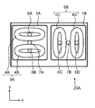
- FIG. 1 is an exploded perspective view of an induction heating cooker 20A according to Embodiment 1 of the present disclosure.
- FIG. 2 is a plan view of the induction heating cooker 20A in a state where the top plate 1 is seen through. It is a top view which shows arrangement
- FIG. 3 is a block diagram of induction heating cooker 20A according to the first embodiment.
- the induction heating cooker 20A includes a top plate 1 and a housing 3.
- a heating coil unit 5A In the housing 3, a heating coil unit 5A, a heating coil unit 5B, and a control unit 9 are provided.
- the top plate 1 covers the upper part of the housing 3 and is configured such that a pan 2 that is an object to be heated is placed thereon.
- the top plate 1 is made of glass.
- the heating coil units 5A and 5B are arranged below the top plate 1 and configured to induction-heat the pan 2 placed on the top plate 1.
- the control unit 9 controls the heating coil units 5A and 5B.
- the direction from left to right is defined as the x direction
- the depth direction from the front is defined as the y direction
- a direction from the bottom to the top perpendicular to the top plate 1 is defined as the z direction.
- the induction heating cooker 20A has sections 1A and 1B on the top plate 1.
- the section 1A is located above the heating coil unit 5A, and the section 1B is located above the heating coil unit 5B.
- the heating coil units 5A and 5B when the pan 2 is placed across the heating coil units 5A and 5B, the heating coil units 5A and 5B can be linked to operate as one heating region.
- the heating coil units 5A and 5B can also be used individually.
- the heating coil unit 5A includes heating coils 4A and 4B, an inverter 10A, and relays 11A and 11B.
- the heating coils 4A and 4B have a substantially elliptical shape having a major axis and a minor axis in plan view, the major axis faces the first direction (x direction), and is adjacent to the minor axis direction (y direction). Arranged.
- the relay 11A is turned on or off by the controller 9 to connect or disconnect the path between the inverter 10A and the heating coil 4A.
- Relay 11B is turned on or off by control unit 9 to connect or disconnect the path between inverter 10A and heating coil 4B.
- the heating coil unit 5B includes heating coils 4C and 4D, an inverter 10B, and relays 11C and 11D.
- the heating coils 4C and 4D have a substantially elliptical shape having a major axis and a minor axis in plan view, the major axis faces the second direction (y direction), and is adjacent to the minor axis direction (x direction). Arranged.
- the relay 11C is turned on or off by the control unit 9, and connects or disconnects the path between the inverter 10B and the heating coil 4C.
- Relay 11D is turned on or off by control unit 9 to connect or disconnect the path between inverter 10B and heating coil 4D.
- the heating coil units 5A and 5B correspond to first and second heating coil units, respectively.
- Relays 11A to 11D correspond to first to fourth switching units, respectively.
- Inverter 10A is connected to heating coil 4A via relay 11A, and is controlled by control unit 9 to supply high-frequency current to heating coil 4A.
- the inverter 10A is connected to the heating coil 4B via the relay 11B, and is controlled by the control unit 9 to supply a high-frequency current to the heating coil 4B.
- the inverter 10B is connected to the heating coil 4C via the relay 11C, and is controlled by the control unit 9 to supply a high-frequency current to the heating coil 4C.
- the inverter 10B is connected to the heating coil 4D via the relay 11D, and is controlled by the control unit 9 to supply a high-frequency current to the heating coil 4D.
- the inverters 10A and 10B may be connected to three or more heating coils.
- inverters 10A and 10B correspond to first and second inverters, respectively.
- the heating coils 4A to 4D have a substantially oval shape in plan view.
- the oval shape is not limited to a typical one having two focal points.
- the oval need only have at least a major axis and a minor axis, and may have an outer shape including a straight portion.
- the heating coils 4A to 4D having an elliptical shape can increase the output as compared with the case where two circular coils are used, thereby improving the heating efficiency.
- the heating coils 4A and 4B have a long diameter oriented in the x direction.
- the heating coils 4C and 4D have a long diameter in the y direction. That is, the major axis of the heating coils 4A, 4B is orthogonal to the major axis of the heating coils 4C, 4D. With this arrangement, heating by a single heating coil unit and heating by interlocking two heating coil units are possible.
- the pan 2 when the pan 2 is placed on the top plate 1 so as to cover the heating coil unit 5A and a part of the heating coil unit 5B, the heating coils 4A and 4B of the heating coil unit 5A, The pan 2 can be heated using the heating coil 4C of the heating coil unit 5B. In this way, the size of the heating region can be appropriately changed according to the size of the pan.
- the heating coils 4A to 4D correspond to first to fourth heating coils, respectively.
- the induction heating cooker 20A has a plurality of temperature sensors (thermistors, infrared sensors) in order to directly or indirectly measure the temperature of the pan 2.
- a thermistor 6A, a thermistor 6B, a thermistor 6C, and a thermistor 6D are provided at the centers of the heating coils 4A, 4B, 4C, and 4D, respectively.
- Infrared sensors 7A and 7B are provided between the heating coil 4A and the heating coil 4B and between the heating coil 4C and the heating coil 4D, respectively.
- the infrared sensors 7A and 7B Two types of infrared sensors having different detectable ranges may be used as the infrared sensors 7A and 7B.
- the infrared sensor 7A arranged between the heating coils 4A and 4B may have a detectable range whose lower limit is 70 ° C.
- Infrared sensor 7B arranged between heating coils 4C and 4D may have a detectable range whose lower limit is 140 ° C.
- a temperature sensor may be provided between the heating coil units 5A and 5B. Even when the pan 2 is placed across the heating coil units 5A and 5B, the temperature of the pan 2 can be detected more accurately by this temperature sensor.
- the thermistor 6A may be provided near the outer periphery of the heating coil 4A on the side opposite to the heating coil 4B.
- the thermistor 6B may be provided near the outer periphery of the heating coil 4B opposite to the heating coil 4A.
- the thermistor 6C may be provided near the outer periphery of the heating coil 4C opposite to the heating coil 4D.
- the thermistor 6D may be provided near the outer periphery of the heating coil 4D opposite to the heating coil 4C.
- the induction heating cooker 20 ⁇ / b> A includes a display unit 8 provided on the top plate 1.
- the display unit 8 is controlled by the control unit 9 and turns on an area corresponding to the heating coil on which the pan 2 is placed when the display unit 8 is regarded as the top plate 1.
- the display unit 8 recognizes the difference in the situation when one pan is placed across a plurality of heating coils or when a plurality of pans are placed separately on a plurality of heating coil units. Thus, the area
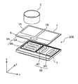
- FIG. 4 is an exploded perspective view of induction heating cooker 20B according to a modification of the present embodiment.
- FIG. 5 is a plan view of the induction heating cooker 20B in a state where the top plate 1 is seen through. The dotted line shown in FIG. 5 represents that the pan 2 is placed across the sections 1A and 1B.
- the induction heating cooker 20B has substantially the same configuration as the induction heating cooker 20A.
- the induction heating cooker 20B is different from the induction heating cooker 20A in that the interval between the heating coil 4C and the heating coil 4D in the induction heating cooker 20B is wider than that of the induction heating cooker 20A.
- the heating coil 4C and the heating coil 4D are separated from each other, even when the pan 2 is placed across the heating coil units 5A and 5B, the pan 2 does not easily reach the region above the heating coil 4D. In the case where the two pans are heated by the heating coils 4C and 4D, the heating of the two pans can be prevented from interfering with each other.
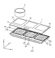
- FIG. 6 is an exploded perspective view of the induction heating cooker 20C according to the second embodiment of the present disclosure.
- FIG. 7 is a plan view of the induction heating cooker 20C in a state where the top plate 1 is seen through. The dotted line shown in FIG. 7 represents that the pan 2 is placed across the sections 1A and 1B.
- the induction heating cooker 20C includes a heating coil unit 5C adjacent to the x direction side of the heating coil unit 5B in addition to the configuration of the induction heating cooker 20A. That is, the heating coil unit 5B is disposed between the heating coil units 5A and 5C.
- the heating coil unit 5C has the same configuration as the heating coil unit 5A shown in FIG. That is, the heating coil unit 5C includes a heating coil 4E, a heating coil 4F, an inverter (not shown), and two relays (not shown). The inverter and the two relays are controlled by the control unit 9.
- the heating coils 4E and 4F have a substantially elliptical shape having a major axis and a minor axis in plan view, the major axis faces the first direction (x direction), and is adjacent to the minor axis direction (y direction). Arranged. That is, the major axis of the heating coils 4E and 4F is orthogonal to the major axis of the heating coils 4C and 4D.
- the third inverter is connected to the heating coils 4E and 4F via two relays, and supplies a high-frequency current to the heating coils 4E and 4F.
- Thermistors 6E and 6F are provided at the centers of the heating coils 4E and 4F, respectively.
- An infrared sensor 7C is provided between the heating coil 4E and the heating coil 4F.
- the infrared sensor 7C may have a detectable range whose lower limit is 70 ° C.
- a temperature sensor may be provided between the heating coil units 5B and 5C. Even when the pan 2 is placed across the heating coil units 5B and 5C, the temperature of the pan 2 can be detected more accurately by this temperature sensor.
- a section 1C is configured on the top plate 1 located above the heating coil unit 5C.
- the induction heating cooker 20C can heat the two pots using the heating coil units 5A and 5C, for example.
- the induction heating cooker 20C can also heat the pans in conjunction with the heating coil units 5A and 5B. .
- the heating coil 4C functions as an auxiliary heating coil of the heating coil unit 5A.
- the heating coil unit 5C corresponds to a third heating coil unit.
- the heating coils 4E and 4F correspond to the fifth and sixth heating coils, respectively.
- the inverter and the two relays included in the heating coil unit 5C correspond to a third inverter, a fifth switching unit, and a sixth switching unit, respectively.
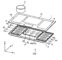
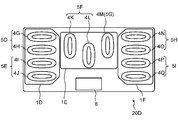
- FIG. 8 is an exploded perspective view of the induction heating cooker 20D according to the third embodiment of the present disclosure.
- FIG. 9A is a plan view of the induction heating cooker 20D in a state where the top plate 1 is seen through.
- the induction heating cooker 20D has sections 1D, 1E, and 1F on the top board 1.
- the heating coil units 5D and 5E are arranged adjacent to each other below the section 1D.
- the heating coil unit 5D includes a heating coil 4G and a heating coil 4H.
- the heating coil unit 5E includes a heating coil 4I and a heating coil 4J.
- the heating coils 4G to 4J are disposed adjacent to each other in the minor axis direction (y direction) with the major axis pointing in the first direction (x direction).
- the heating coil units 5F and 5G are arranged adjacent to each other below the section 1E.
- the heating coil unit 5F includes a heating coil 4K and a heating coil 4L.
- the heating coil unit 5G includes a heating coil 4M.
- the heating coils 4K to 4M are disposed adjacent to each other in the minor axis direction (x direction) with the major axis pointing in the second direction (y direction).
- the heating coil units 5H and 5I are arranged adjacent to each other below the section 1F.
- the heating coil unit 5H includes a heating coil 4N and a heating coil 4O.
- the heating coil unit 5I includes a heating coil 4P and a heating coil 4Q.
- the heating coils 4N to 4Q are disposed adjacent to each other in the minor axis direction (y direction) with the major axis pointing in the first direction (x direction).
- each of the heating coil units 5D to 5F, 5H, and 5I further includes an inverter and two relays (both not shown). One of the two relays is provided between the inverter and one of the two heating coils, and the other of the two relays is provided between the inverter and the other of the two heating coils.
- the heating coil unit 5G has an inverter connected to the heating coil 4M.
- the control unit controls all inverters and all relays. Each inverter drives one or two heating coils included in each heating coil unit.
- a thermistor 6G At the center of the heating coils 4G to 4Q, a thermistor 6G, a thermistor 6H, a thermistor 6I, a thermistor 6J, a thermistor 6K, a thermistor 6L, a thermistor 6M, a thermistor 6N, a thermistor 6P, and a thermistor 6Q are provided.
- An infrared sensor 7D, an infrared sensor 7E, and an infrared sensor 7F are provided between the heating coil 4G and the heating coil 4H, between the heating coil 4H and the heating coil 4I, and between the heating coil 4I and the heating coil 4J, respectively. .
- An infrared sensor 7G and an infrared sensor 7H are provided between the heating coil 4K and the heating coil 4L and between the heating coil 4L and the heating coil 4M, respectively.
- An infrared sensor 7I, an infrared sensor 7J, and an infrared sensor 7K are provided between the heating coil 4N and the heating coil 4O, between the heating coil 4O and the heating coil 4P, and between the heating coil 4P and the heating coil 4Q, respectively. .
- the induction heating cooker 20D can heat each of the plurality of pans using the heating coil units 5D to 5I.
- the heating coil units 5D and 5F can be linked to heat the pan.
- the heating coil units 5G and 5H can be linked to heat the pan.
- the heating coil units 5D, 5F, and 5H correspond to the first, second, and third heating coil units, respectively.
- the heating coils 4D and 4E correspond to the first and second heating coils, respectively.
- the heating coils 4K and 4L correspond to the third and fourth heating coils, respectively.
- the heating coils 4O and 4P correspond to the fifth and sixth heating coils, respectively.
- the inverter and two relays included in the heating coil unit 5D correspond to a first inverter, a first switching unit, and a second switching unit, respectively.
- the inverter and the two relays included in the heating coil unit 5F correspond to the second inverter, the third switching unit, and the fourth switching unit, respectively.
- the inverter and two relays included in the heating coil unit 5H correspond to a third inverter, a fifth switching unit, and a sixth switching unit, respectively.
- FIG. 9B and FIG. 9C are plan views of modifications of the induction heating cooker 20D.
- the heating coils 4K to 4M are arranged in a zigzag manner.
- the heating coils 4K, 4L, and 4M are arranged obliquely.
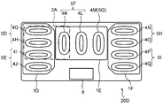
- FIG. 10A and FIG. 11A are plan views of an induction heating cooker 20D that schematically shows a situation where a pan is placed across a plurality of heating coils.
- the dotted lines shown in FIGS. 10A and 10B indicate that the pans 2A and 2B are placed across the sections 1D and 1E.
- FIG. 10B and FIG. 11B show displays on the display unit 8 for expressing the situation shown in FIG. 10A and FIG. 11A, respectively.
- the pan 2A is placed across the heating coils 4G, 4H, 4I and the heating coil 4K.
- the display unit 8 lights an area corresponding to the placement position of the pan 2A (hereinafter, this area is referred to as a lighting area 8A). ).
- the lighting region 8A is a region in the display unit 8 corresponding to the heating coils 4G, 4H, 4I, and 4K.
- the boundary mark 8B represents the boundary between two adjacent heating coils.
- the pan 2B is placed across the associated heating coils 4G and 4H and the heating coil 4K.
- the display unit 8 lights an area corresponding to the placement position of the pan 2B.
- the lighting region 8A is a region corresponding to the heating coils 4G, 4H, and 4K.
- the display unit 8 displays the placement status of the pan 2B placed across a plurality of heating coils so that the pan 2B can be visually recognized as a single object.
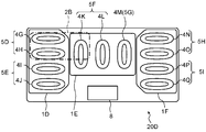
- 12A to 12L are plan views of the induction heating cooker 20D schematically showing a state in which pans having various widths are placed across a plurality of sections.
- the pan 2A is placed across the heating coils 4G to 4I related to the section 1D and the heating coil 4K related to the section 1E.
- both relays are turned on in the heating coil unit 5D.
- the relay corresponding to the heating coil 4I is turned on, and the relay corresponding to the heating coil 4J is turned off.
- the relay corresponding to the heating coil 4K is turned on, and the relay corresponding to the heating coil 4L is turned off.
- the pan 2A is heated by the heating coils 4G to 4I and 4K by interlocking the three inverters included in the heating coil units 5D to 5F.
- the pan 2C is placed across the heating coils 4G to 4I related to the section 1D and the heating coils 4K and 4L related to the section 1E.
- both relays are turned on in the heating coil unit 5D.
- the relay corresponding to the heating coil 4I is turned on, and the relay corresponding to the heating coil 4J is turned off.
- both relays are turned on.
- the pan 2C is heated by the heating coils 4G to 4I, 4K, and 4L by interlocking the three inverters included in the heating coil units 5D to 5F.
- the pan 2D is placed across the heating coils 4G to 4I related to the section 1D and the heating coils 4K to 4M related to the section 1E. In this case, the pan 2D is heated by the heating coils 4G to 4I and 4K to 4M.
- both relays are turned on in the heating coil unit 5D.
- the relay corresponding to the heating coil 4I is turned on, and the relay corresponding to the heating coil 4J is turned off.
- both relays are turned on.
- the pan 2D is heated by the heating coils 4G to 4I and 4K to 4M by interlocking the four inverters included in the heating coil units 5D to 5G.
- the pan 2E is placed across the heating coils 4G to 4I related to the section 1D, the heating coils 4K to 4M related to the section 1E, and the heating coils 4N to 4P related to the section 1F. Yes.
- both relays are turned on in the heating coil unit 5D.
- the relay corresponding to the heating coil 4I is turned on, and the relay corresponding to the heating coil 4J is turned off.
- both relays are turned on.
- both relays are turned on.
- the relay corresponding to the heating coil 4P is turned on, and the relay corresponding to the heating coil 4Q is turned off.
- the pan 2E is heated by the heating coils 4G to 4I, 4K to 4M, and 4N to 4P by interlocking the six inverters included in the heating coil units 5D to 5I.
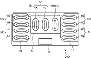
- the pan 2B is placed across the heating coils 4G and 4H related to the section 1D and the heating coil 4K related to the section 1E. In this case, the pan 2B is heated by the heating coils 4G, 4H, and 4K.
- both relays are turned on in the heating coil unit 5D.
- the relay corresponding to the heating coil 4K is turned on, and the relay corresponding to the heating coil 4L is turned off.
- the pan 2B is heated by the heating coils 4G, 4H, and 4K by interlocking the two inverters included in the heating coil units 5D and 5F.
- the pan 2F is placed across the heating coils 4G and 4H related to the section 1D and the heating coils 4K and 4L related to the section 1E.
- both relays are turned on in the heating coil unit 5D.
- both relays are turned on.
- the pan 2F is heated by the heating coils 4G, 4H, 4K, and 4L by interlocking the two inverters included in the heating coil units 5D and 5F.
- the pan 2G is placed across the heating coils 4G and 4H related to the section 1D and the heating coils 4K to 4M related to the section 1E.
- both relays are turned on in the heating coil unit 5D.
- both relays are turned on.
- the pan 2G is heated by the heating coils 4G, 4H, 4K to 4M by interlocking the three inverters included in the heating coil units 5D, 5F, and 5G.
- the pan 2H is placed across the heating coils 4G and 4H related to the section 1D, the heating coils 4K to 4M related to the section 1E, and the heating coils 4N and 4O related to the section 1F. Yes.
- both relays are turned on in the heating coil unit 5D.
- both relays are turned on.
- both the two relays are turned on.
- the pan 2H is heated by the heating coils 4G, 4H, 4K to 4M, 4N, and 4O by interlocking the four inverters included in the heating coil units 5D, 5F, 5G, and 5H.
- the pan 2B is placed across the heating coils 4H and 4I related to the section 1D and the heating coil 4K related to the section 1E.
- the relay corresponding to the heating coil 4G is turned off, and the relay corresponding to the heating coil 4H is turned on.
- the relay corresponding to the heating coil 4I is turned on, and the relay corresponding to the heating coil 4J is turned off.
- the relay corresponding to the heating coil 4K is turned on, and the relay corresponding to the heating coil 4L is turned off.
- the pan 2B is heated by the heating coils 4H, 4I, and 4K by interlocking the three inverters included in the heating coil units 5D to 5F.
- the pan 2F is placed across the heating coils 4H and 4I related to the section 1D and the heating coils 4K and 4L related to the section 1E.
- the relay corresponding to the heating coil 4G is turned off, and the relay corresponding to the heating coil 4H is turned on.
- the relay corresponding to the heating coil 4I is turned on, and the relay corresponding to the heating coil 4J is turned off.
- both relays are turned on.
- the pan 2F is heated by the heating coils 4H, 4I, 4K, and 4L by interlocking the three inverters included in the heating coil units 5D to 5F.
- the pan 2G is placed across the heating coils 4H and 4I related to the section 1D and the heating coils 4K to 4M related to the section 1E.
- the relay corresponding to the heating coil 4G is turned off, and the relay corresponding to the heating coil 4H is turned on.
- the relay corresponding to the heating coil 4I is turned on, and the relay corresponding to the heating coil 4J is turned off.
- both relays are turned on.
- the pan 2G is heated by the heating coils 4H, 4I, 4K to 4M by interlocking the four inverters included in the heating coil units 5D to 5G.
- the pan 2H is placed across the heating coils 4H and 4I related to the section 1D, the heating coils 4K to 4M related to the section 1E, and the heating coils 4O and 4P related to the section 1F. Yes.
- the relay corresponding to the heating coil 4G is turned off, and the relay corresponding to the heating coil 4H is turned on.
- the relay corresponding to the heating coil 4I is turned on, and the relay corresponding to the heating coil 4J is turned off.
- both relays are turned on.
- the relay corresponding to the heating coil 4N is turned off, and the relay corresponding to the heating coil 4O is turned on.
- the relay corresponding to the heating coil 4P is turned on, and the relay corresponding to the heating coil 4Q is turned off.
- the pan 2H is heated by the heating coils 4H, 4I, 4K to 4M, 4O, and 4P by interlocking the six inverters included in the heating coil units 5D to 5I.
- pans 2A to 2H having different sizes are placed across a plurality of heating coils
- the pan is placed above.
- the heating coil can be activated.
- size of the mounted pan the position and magnitude
- FIGS. 13A to 13I are plan views of the induction heating cooker 20D schematically showing a state where two pans of various sizes are placed across a plurality of sections.
- FIG. 13A two pans 2A are placed on induction heating cooker 20D.
- one of the two pans 2A is placed across the heating coils 4G to 4I related to the section 1D and the heating coil 4K related to the section 1E.
- the other of the two pans 2A is placed across the heating coil 4M related to the section 1E and the heating coils 4N to 4P related to the section 1F.
- both relays are turned on in the heating coil unit 5D.
- the relay corresponding to the heating coil 4I is turned on, and the relay corresponding to the heating coil 4J is turned off.
- the relay corresponding to the heating coil 4K is turned on, and the relay corresponding to the heating coil 4L is turned off.
- both relays are turned on.
- the relay corresponding to the heating coil 4P is turned on, and the relay corresponding to the heating coil 4Q is turned off.
- one of the two pans 2A is heated by the heating coils 4G to 4I and 4K by interlocking the three inverters included in the heating coil units 5D to 5F.
- the other of the two pans 2A is heated by the heating coils 4M to 4P.
- pans 2A and 2B are placed on induction heating cooker 20D.
- the pan 2A is placed across the heating coils 4G to 4I related to the section 1D and the heating coil 4K related to the section 1E.
- the pan 2B is placed across the heating coil 4M related to the section 1E and the heating coils 4N and 4O related to the section 1F.
- both relays are turned on in the heating coil unit 5D.
- the relay corresponding to the heating coil 4I is turned on, and the relay corresponding to the heating coil 4J is turned off.
- the heating coil unit 5F the relay corresponding to the heating coil 4K is turned on, and the relay corresponding to the heating coil 4L is turned off.
- both the two relays are turned on.
- the pan 2A is heated by the heating coils 4G to 4I and 4K by interlocking the three inverters included in the heating coil units 5D to 5F.
- the pan 2B is heated by the heating coils 4M to 4O by interlocking the two inverters included in the heating coil units 5G and 5H.
- pans 2A and 2B are placed on induction heating cooker 20D.
- the pan 2A is placed across the heating coils 4G to 4I related to the section 1D and the heating coil 4K related to the section 1E.
- the pan 2B is placed across the heating coil 4M related to the section 1E and the heating coils 4O and 4P related to the section 1F.
- both relays are turned on in the heating coil unit 5D.
- the relay corresponding to the heating coil 4I is turned on, and the relay corresponding to the heating coil 4J is turned off.
- the relay corresponding to the heating coil 4K is turned on, and the relay corresponding to the heating coil 4L is turned off.
- the relay corresponding to the heating coil 4N is turned off, and the relay corresponding to the heating coil 4O is turned on.
- the relay corresponding to the heating coil 4P is turned on, and the relay corresponding to the heating coil 4Q is turned off.
- the pan 2A is heated by the heating coils 4G to 4I and 4K by interlocking the three inverters included in the heating coil units 5D to 5F.
- the pan 2B is heated by the heating coils 4M, 4O, and 4P by interlocking the three inverters included in the heating coil units 5G to 5I.
- pans 2A and 2B are placed on induction heating cooker 20D.
- the pan 2A is placed across the heating coil 4M related to the section 1E and the heating coils 4N to 4P related to the section 1F.
- the pan 2B is placed across the heating coils 4G and 4H related to the section 1D and the heating coil 4K related to the section 1E.
- both relays are turned on in the heating coil unit 5D.
- the relay corresponding to the heating coil 4K is turned on, and the relay corresponding to the heating coil 4L is turned off.
- both relays are turned on.
- the relay corresponding to the heating coil 4P is turned on, and the relay corresponding to the heating coil 4Q is turned off.
- the pan 2B is heated by the heating coils 4G, 4H, and 4K by interlocking the two inverters included in the heating coil units 5D and 5F.
- the pan 2A is heated by the heating coils 4M to 4P by interlocking the three inverters included in the heating coil units 5G to 5I.
- two pans 2B are placed on the induction heating cooker 20D.
- one of the two pans 2B is placed across the heating coils 4G and 4H related to the section 1D and the heating coil 4K related to the section 1E.
- the other of the two pans 2B is placed across the heating coil 4M related to the section 1E and the heating coils 4N and 4O related to the section 1F.
- both relays are turned on in the heating coil unit 5D.
- the relay corresponding to the heating coil 4K is turned on, and the relay corresponding to the heating coil 4L is turned off.
- both the two relays are turned on.
- one of the two pans 2B is heated by the heating coils 4G, 4H, and 4K by interlocking the two inverters included in the heating coil units 5D and 5F.
- the other of the two pans 2B is heated by the heating coils 4M to 4O.
- two pans 2B are placed on the induction heating cooker 20D.
- one of the two pans 2B is placed across the heating coils 4G and 4H related to the section 1D and the heating coil 4K related to the section 1E.
- the other of the two pans 2B is placed across the heating coil 4M related to the section 1E and the heating coils 4O and 4P related to the section 1F.
- both relays are turned on in the heating coil unit 5D.
- the relay corresponding to the heating coil 4K is turned on, and the relay corresponding to the heating coil 4L is turned off.
- the relay corresponding to the heating coil 4N is turned off, and the relay corresponding to the heating coil 4O is turned on.
- the relay corresponding to the heating coil 4P is turned on, and the relay corresponding to the heating coil 4Q is turned off.
- one of the two pans 2B is heated by the heating coils 4G, 4H, and 4K by interlocking the two inverters included in the heating coil units 5D and 5F.
- the other of the two pans 2B is heated by the heating coils 4M, 4O, and 4P.
- pans 2A and 2B are placed on induction heating cooker 20D.
- the pan 2A is placed across the heating coils 4N to 4P related to the section 1F and the heating coil 4M related to the section 1E.
- the pan 2B is placed across the heating coils 4H and 4I related to the section 1D and the heating coil 4K related to the section 1E.
- the relay corresponding to the heating coil 4G is turned off, and the relay corresponding to the heating coil 4H is turned on.
- the relay corresponding to the heating coil 4I is turned on, and the relay corresponding to the heating coil 4J is turned off.
- the relay corresponding to the heating coil 4K is turned on, and the relay corresponding to the heating coil 4L is turned off.
- both relays are turned on.
- the relay corresponding to the heating coil 4P is turned on, and the relay corresponding to the heating coil 4Q is turned off.
- the pan 2B is heated by the heating coils 4H, 4I, and 4K by interlocking the three inverters included in the heating coil units 5D to 5F.
- the pan 2A is heated by the heating coils 4M to 4P by interlocking the three inverters included in the heating coil units 5G to 5I.
- FIG. 13H two pans 2B are placed on induction heating cooker 20D.
- one of the two pans 2B is placed across the heating coils 4H and 4I related to the section 1D and the heating coil 4K related to the section 1E.
- the other of the two pans 2B is placed across the heating coils 4N and 4O related to the section 1F and the heating coil 4M related to the section 1E.
- the relay corresponding to the heating coil 4G is turned off, and the relay corresponding to the heating coil 4H is turned on.
- the relay corresponding to the heating coil 4I is turned on, and the relay corresponding to the heating coil 4J is turned off.
- the relay corresponding to the heating coil 4K is turned on, and the relay corresponding to the heating coil 4L is turned off.
- both the two relays are turned on.
- one of the two pans 2B is heated by the heating coils 4H, 4I, and 4K by interlocking the three inverters included in the heating coil units 5D to 5F.
- the other of the two pans 2B is heated by the heating coils 4M to 4O.
- FIG. 13I two pans 2B are placed on the induction heating cooker 20D.
- one of the two pans 2B is placed across the heating coils 4H and 4I related to the section 1D and the heating coil 4K related to the section 1E.
- the other of the two pans 2B is placed across the heating coils 4O and 4P related to the section 1F and the heating coil 4M related to the section 1E.
- the relay corresponding to the heating coil 4G is turned off, and the relay corresponding to the heating coil 4H is turned on.
- the relay corresponding to the heating coil 4I is turned on, and the relay corresponding to the heating coil 4J is turned off.
- the relay corresponding to the heating coil 4K is turned on, and the relay corresponding to the heating coil 4L is turned off.
- the relay corresponding to the heating coil 4N is turned off, and the relay corresponding to the heating coil 4O is turned on.
- the relay corresponding to the heating coil 4P is turned on, and the relay corresponding to the heating coil 4Q is turned off.
- one of the two pans 2B is heated by the heating coils 4H, 4I, and 4K by interlocking the three inverters included in the heating coil units 5D to 5F.
- the other of the two pans 2B is heated by the heating coils 4M, 4O, and 4P.
- pans 2A and 2B having different sizes are placed across a plurality of heating coils
- the pan is placed above.
- the heating coil can be activated.
- size of the mounted pan the position and magnitude
- FIG. 14A and FIG. 14B are diagrams schematically showing a state in which the pan 2 is placed on the sections 1D and 1E, respectively.
- the pan 2 is placed so as to cover the heating coils 4G to 4I related to the section 1D and the heating coils 4K and 4L related to the section 1E.
- the pan 2 is placed so as to cover the heating coils 4G to 4I related to the section 1D and a small part of the heating coil 4K related to the section 1E.
- FIG. 15 is a flowchart showing the heating control when the pan is placed across the section 1D and the section 1E. As shown in FIG. 15, in step S01, it is determined whether or not the pan 2 is placed so as to cover the heating coil at a certain rate or more.
- step S01 when the pan 2 is placed so as to cover the entire heating coil 4K and almost the entire heating coil 4L, the process proceeds from step S01 to step S02.
- step S02 the power of the heating coils 4K and 4L is made larger than the power per heating coil related to the section 1D.
- the power density in the heating coil related to the section 1E can be made the same as the power density in the heating coil related to the section 1D.
- the heating coils 4K and 4L function as auxiliary heating coils that assist the heating coil units 5D and 5E.
- step S01 when the pan 2 is placed so as to cover only a small part of the heating coil 4K in the section 1E, the process proceeds from step S01 to step S03.
- step S03 the heating coil related to the section 1E is supplied with power smaller than the power supplied to the heating coil related to the section 1D. Thereby, heating unevenness is suppressed.
- the heating coil 4K functions as an auxiliary heating coil that assists the heating coil units 5D and 5E.
- the infrared sensors 7D, 7E, and 7F have a detectable range whose lower limit is 70 ° C.
- the infrared sensors 7D and 7E have a detectable range whose lower limit is 140 ° C.
- the control unit 9 When the pan 2 is placed across the section 1D and the section 1E, the control unit 9 performs heating related to the section 1E based on detection values by the infrared sensors 7A to 7F having a large detectable range related to the section 1D. Coils 4K to 4M are controlled. Thus, the heating coils 4K to 4M related to the section 1E are interlocked with the heating coils 4G to 4J related to the section 1D. As a result, heating unevenness is suppressed.
- the present disclosure is applicable to an induction heating cooker having a plurality of heating coils.
Landscapes
- Physics & Mathematics (AREA)
- Electromagnetism (AREA)
- Induction Heating Cooking Devices (AREA)
Abstract
誘導加熱調理器は、互いに隣接して設けられた第1、第2の加熱コイルユニットと、第1、第2の加熱コイルユニットを制御する制御部とを備える。第1の加熱コイルユニットは、第1、第2の加熱コイルと第1のインバータとを有する。第2の加熱コイルユニットは、第3、第4の加熱コイルと第2のインバータとを有する。第1から第4の加熱コイルは、平面視で長径と短径とを有する楕円形状を有する。第1、第2の加熱コイルは、第1の方向に向く長径を有し、短径の方向に互いに隣接して設けられる。第3、第4の加熱コイルは、第1の方向と直交する第2の方向に向く長径を有し、短径の方向に互いに隣接して設けられる。第1のインバータは、第1、第2の加熱コイルに高周波電流を供給する。第2のインバータは、第3、第4の加熱コイルに高周波電流を供給する。本態様によれば、載置される鍋の大きさに応じて、加熱領域の大きさを適宜変更することができる。
Description
本開示は、複数の加熱コイルを備えた誘導加熱調理器に関する。
従来、誘導加熱調理器において、一つの加熱コイルの大きさによって決定される加熱領域の大きさを超える鍋を用いるのは困難であった。
近年の特許出願には、複数の加熱コイルを用いて一つの鍋を加熱する誘導加熱調理器が開示される(例えば、特許文献1、2参照)。
特許文献1に記載の誘導加熱調理器は、互いに近接して配置された、平面視で楕円形の形状を有する二つの加熱コイルを有する。この誘導加熱調理器によれば、鍋の載置状況に応じて二つの加熱コイルが作動する。特許文献2に記載の誘導加熱調理器は、各々が複数の加熱コイルを含む二つの加熱領域と、それらの加熱領域の間に配置された一つの補助加熱コイルとを有する。
特許文献1に記載の誘導加熱調理器は、一つの鍋を加熱するために二つの加熱コイルを同時に作動させる。このため、二つの加熱コイルは、単一の加熱領域として機能する。特許文献2に記載の誘導加熱調理器において、補助加熱コイルは、単独で作動するのではなく、常に二つの加熱領域のいずれかとともに作動するものである。
本開示は、載置された鍋の位置および大きさに応じて、加熱領域の位置および大きさを適宜変更することができる誘導加熱調理器を提供することを目的とする。
本開示の一態様の誘導加熱調理器は、被加熱物が載置されるように構成された天板と、天板の下方に互いに隣接して設けられた第1の加熱コイルユニットおよび第2の加熱コイルユニットと、第1の加熱コイルユニットと第2の加熱コイルユニットとを制御するように構成された制御部とを備える。
第1の加熱コイルユニットは、第1の加熱コイルと第2の加熱コイルと第1のインバータとを有する。第2の加熱コイルユニットは、第3の加熱コイルと第4の加熱コイルと第2のインバータとを有する。
第1から第4の加熱コイルは、平面視で長径と短径とを有する楕円形状を有する。
第1および第2の加熱コイルは、第1の方向に向く長径を有し、短径の方向に互いに隣接して設けられる。第3および第4の加熱コイルは、第1の方向と直交する第2の方向に向く長径を有し、短径の方向に互いに隣接して設けられる。
第1のインバータは、第1および第2の加熱コイルに高周波電流を供給するように構成される。第2のインバータは、第3および第4の加熱コイルに高周波電流を供給するように構成される。
本態様によれば、上方に鍋が載置された加熱コイルを作動させることにより、載置される鍋の位置および大きさに応じて、加熱領域の位置および大きさを適宜変更することができる。
本開示の第1の態様の誘導加熱調理器は、被加熱物が載置されるように構成された天板と、天板の下方に互いに隣接して設けられた第1の加熱コイルユニットおよび第2の加熱コイルユニットと、第1の加熱コイルユニットと第2の加熱コイルユニットとを制御するように構成された制御部とを備える。
第1の加熱コイルユニットは、第1の加熱コイルと第2の加熱コイルと第1のインバータとを有する。第2の加熱コイルユニットは、第3の加熱コイルと第4の加熱コイルと第2のインバータとを有する。
第1から第4の加熱コイルは、平面視で長径と短径とを有する楕円形状を有する。
第1および第2の加熱コイルは、第1の方向に向く長径を有し、短径の方向に互いに隣接して設けられる。第3および第4の加熱コイルは、第1の方向と直交する第2の方向に向く長径を有し、短径の方向に互いに隣接して設けられる。
第1のインバータは、第1および第2の加熱コイルに高周波電流を供給するように構成される。第2のインバータは、第3および第4の加熱コイルに高周波電流を供給するように構成される。
本開示の第2の態様の誘導加熱調理器によれば、第1の態様において、第1の加熱コイルユニットが、第2の加熱コイルユニットの第3の加熱コイルの側に設けられる。
本開示の第3の態様の誘導加熱調理器によれば、第1の態様において、第2の方向が天板の奥行き方向である。
本開示の第4の態様の誘導加熱調理器によれば、第1の態様において、第1の加熱コイルユニットが、第1の加熱コイルと第1のインバータとの間に設けられた第1の切替部と、第2の加熱コイルと第1のインバータとの間に設けられた第2の切替部とを有する。
第2の加熱コイルユニットが、第3の加熱コイルと第2のインバータとの間に設けられた第3の切替部と、第4の加熱コイルと第2のインバータとの間に設けられた第4の切替部とを有する。
本開示の第5の態様の誘導加熱調理器によれば、第1の態様において、第1の加熱コイルユニットが、第1の加熱コイルと第2の加熱コイルとの間に設けられた温度センサを有する。第2の加熱コイルユニットが、第3の加熱コイルと第4の加熱コイルとの間に設けられた温度センサを有する。
本開示の第6の態様の誘導加熱調理器は、第1の態様に加えて、天板の下方に第2の加熱コイルユニットに隣接して設けられ、制御部により制御される第3の加熱コイルユニットをさらに有する。
第3の加熱コイルユニットは、第5の加熱コイルと第6の加熱コイルと第3のインバータとを有する。第5および第6の加熱コイルは、平面視で長径と短径とを有する楕円形状を有する。第5および第6の加熱コイルは、第1の方向に向く長径を有し、短径の方向に互いに隣接して設けられる。第3のインバータは、第5および第6の加熱コイルに高周波電流を供給するように構成される。
本開示の第7の態様の誘導加熱調理器によれば、第6の態様において、第3の加熱コイルユニットが、第2の加熱コイルユニットの第4の加熱コイルの側に設けられる。
本開示の第8の態様の誘導加熱調理器によれば、第6の態様において、第3の加熱コイルユニットが、第5の加熱コイルと第3のインバータとの間に設けられた第5の切替部と、第6の加熱コイルと第3のインバータとの間に設けられた第6の切替部とを有する。
本開示の第9の態様の誘導加熱調理器によれば、第6の態様において、第3の加熱コイルユニットが、第5の加熱コイルと第6の加熱コイルとの間に設けられた温度センサを有する。
以下、実施の形態に係る誘導加熱調理器について、添付図面を参照しながら説明する。
以下のすべての図において、同一または相当部分には同一の参照符号を付し、重複する説明は省略する。
(実施の形態1)
<全体構成>
図1は、本開示の実施の形態1に係る誘導加熱調理器20Aの分解斜視図である。図2は、誘導加熱調理器20Aの、天板1を透視した状態における平面図である。図1に示す加熱コイルユニット5A、5Bの配置を示す平面図である。図3は、実施の形態1に係る誘導加熱調理器20Aのブロック図である。
<全体構成>
図1は、本開示の実施の形態1に係る誘導加熱調理器20Aの分解斜視図である。図2は、誘導加熱調理器20Aの、天板1を透視した状態における平面図である。図1に示す加熱コイルユニット5A、5Bの配置を示す平面図である。図3は、実施の形態1に係る誘導加熱調理器20Aのブロック図である。
図1~図3に示すように、誘導加熱調理器20Aは、天板1と筐体3とを備える。
筐体3内には、加熱コイルユニット5Aおよび加熱コイルユニット5Bと制御部9とが設けられる。
天板1は、筐体3の上方を覆い、被加熱物である鍋2が載置されるように構成される。例えば、天板1はガラス製である。
加熱コイルユニット5A、5Bは、天板1の下方に配置され、天板1上に載置された鍋2を誘導加熱するように構成される。制御部9は、加熱コイルユニット5A、5Bを制御する。
本開示において、図1に示すように、天板1に平行な水平面において、左から右への方向をx方向、手前からの奥行き方向をy方向と定義する。天板1に対して垂直に下から上への方向をz方向と定義する。
誘導加熱調理器20Aは、天板1上に区画1A、1Bを有する。区画1Aは、加熱コイルユニット5Aの上方に位置し、区画1Bは、加熱コイルユニット5Bの上方に位置する。
誘導加熱調理器20Aによれば、鍋2が加熱コイルユニット5A、5Bに跨って載置された場合、加熱コイルユニット5A、5Bを連動させ、一つの加熱領域として作動させることができる。加熱コイルユニット5A、5Bを個別に使用することもできる。
以下の説明において、簡単のため、例えば「鍋が加熱コイルの上方の天板1に載置される」と表現するべき記述を、「鍋が加熱コイルに載置される」と表現する。
以下、誘導加熱調理器20Aの各要素について説明する。
<加熱コイルユニット>
加熱コイルユニット5Aは、加熱コイル4A、4Bとインバータ10Aとリレー11A、11Bとを有する。加熱コイル4A、4Bは、平面視で長径と短径とを有する略楕円形の形状を有し、長径が第1の方向(x方向)を向き、短径の方向(y方向)に互いに隣接して配置される。
加熱コイルユニット5Aは、加熱コイル4A、4Bとインバータ10Aとリレー11A、11Bとを有する。加熱コイル4A、4Bは、平面視で長径と短径とを有する略楕円形の形状を有し、長径が第1の方向(x方向)を向き、短径の方向(y方向)に互いに隣接して配置される。
加熱コイルユニット5Aにおいて、リレー11Aは、制御部9によりオンまたはオフされて、インバータ10Aと加熱コイル4Aとの間の経路を接続または切断する。リレー11Bは、制御部9によりオンまたはオフされて、インバータ10Aと加熱コイル4Bとの間の経路を接続または切断する。
加熱コイルユニット5Bは、加熱コイル4C、4Dとインバータ10Bとリレー11C、11Dとを有する。加熱コイル4C、4Dは、平面視で長径と短径とを有する略楕円形の形状を有し、長径が第2の方向(y方向)を向き、短径の方向(x方向)に互いに隣接して配置される。
加熱コイルユニット5Bにおいて、リレー11Cは、制御部9によりオンまたはオフされて、インバータ10Bと加熱コイル4Cとの間の経路を接続または切断する。リレー11Dは、制御部9によりオンまたはオフされて、インバータ10Bと加熱コイル4Dとの間の経路を接続または切断する。
本実施の形態では、加熱コイルユニット5A、5Bが、第1、第2の加熱コイルユニットにそれぞれ相当する。リレー11A~11Dが、第1~第4の切替部にそれぞれ相当する。
<インバータ>
インバータ10Aは、リレー11Aを介して加熱コイル4Aに接続され、制御部9に制御されて加熱コイル4Aに高周波電流を供給する。インバータ10Aは、リレー11Bを介して加熱コイル4Bに接続され、制御部9に制御されて加熱コイル4Bに高周波電流を供給する。
インバータ10Aは、リレー11Aを介して加熱コイル4Aに接続され、制御部9に制御されて加熱コイル4Aに高周波電流を供給する。インバータ10Aは、リレー11Bを介して加熱コイル4Bに接続され、制御部9に制御されて加熱コイル4Bに高周波電流を供給する。
インバータ10Bは、リレー11Cを介して加熱コイル4Cに接続され、制御部9に制御されて加熱コイル4Cに高周波電流を供給する。インバータ10Bは、リレー11Dを介して加熱コイル4Dに接続され、制御部9に制御されて加熱コイル4Dに高周波電流を供給する。
インバータ10A、10Bは、三つ以上の加熱コイルに接続されてもよい。
本実施の形態では、インバータ10A、10Bが、第1、第2のインバータにそれぞれ相当する。
<加熱コイル>
上述のように、加熱コイル4A~4Dは、平面視で略楕円形の形状を有する。本実施の形態において、楕円形は、二つの焦点を有する典型的なものに限られない。楕円形は、例えば、少なくとも長径と短径を有していればよく、直線部分を含む外形を有してもよい。ただし、加熱コイル4A~4Dは、角がなく全体として曲線的な外形を有するのが好ましい。
上述のように、加熱コイル4A~4Dは、平面視で略楕円形の形状を有する。本実施の形態において、楕円形は、二つの焦点を有する典型的なものに限られない。楕円形は、例えば、少なくとも長径と短径を有していればよく、直線部分を含む外形を有してもよい。ただし、加熱コイル4A~4Dは、角がなく全体として曲線的な外形を有するのが好ましい。
このように、楕円形の形状を有する加熱コイル4A~4Dにより、二つの円形コイルを用いる場合より出力を大きくすることができ、加熱効率を向上させることができる。
加熱コイル4A、4Bは、x方向に向いた長径を有する。加熱コイル4C、4Dは、y方向に向いた長径を有する。すなわち、加熱コイル4A、4Bの長径は、加熱コイル4C、4Dの長径と直交する。この配置により、単一の加熱コイルユニットによる加熱と、二つの加熱コイルユニットを連動させた加熱とが可能となる。
具体的には、加熱コイルユニット5Aと、加熱コイルユニット5Bの一部とを覆うように、鍋2が天板1上に載置された場合、加熱コイルユニット5Aの加熱コイル4A、4Bと、加熱コイルユニット5Bの加熱コイル4Cとを用いて、鍋2を加熱することができる。このようにして、鍋の大きさに応じて加熱領域の大きさを適宜変更することができる。
本実施の形態では、加熱コイル4A~4Dが、第1~第4の加熱コイルにそれぞれ相当する。
<温度センサ>
誘導加熱調理器20Aは、鍋2の温度を直接または間接に計測するために、複数の温度センサ(サーミスタ、赤外線センサ)を有する。
誘導加熱調理器20Aは、鍋2の温度を直接または間接に計測するために、複数の温度センサ(サーミスタ、赤外線センサ)を有する。
図2に示すように、加熱コイル4A、4B、4C、4Dの中心には、サーミスタ6A、サーミスタ6B、サーミスタ6C、サーミスタ6Dがそれぞれ設けられる。加熱コイル4Aと加熱コイル4Bとの間、および、加熱コイル4Cと加熱コイル4Dとの間には、赤外線センサ7A、7Bがそれぞれ設けられる。
赤外線センサ7A、7Bに、検出可能範囲の異なる2種類の赤外線センサを用いてもよい。例えば、加熱コイル4A、4Bの間に配置された赤外線センサ7Aは、下限値が70℃である検出可能範囲を有してもよい。加熱コイル4C、4Dの間に配置された赤外線センサ7Bは、下限値が140℃である検出可能範囲を有してもよい。
加熱コイルユニット5A、5Bの間に、温度センサを設けてもよい。この温度センサにより、鍋2が加熱コイルユニット5A、5Bに跨って載置された場合でも、より正確に鍋2の温度を検出することができる。
サーミスタ6Aを、加熱コイル4Bと反対側の加熱コイル4Aの外周付近に設けてもよい。サーミスタ6Bを、加熱コイル4Aと反対側の加熱コイル4Bの外周付近に設けてもよい。サーミスタ6Cを、加熱コイル4Dと反対側の加熱コイル4Cの外周付近に設けてもよい。サーミスタ6Dを、加熱コイル4Cと反対側の加熱コイル4Dの外周付近に設けてもよい。
<表示部>
誘導加熱調理器20Aは、天板1に設けられた表示部8を備える。表示部8は、制御部9に制御され、表示部8を天板1に見立てた場合に上方に鍋2が載置された加熱コイルに対応する領域を点灯させる。
誘導加熱調理器20Aは、天板1に設けられた表示部8を備える。表示部8は、制御部9に制御され、表示部8を天板1に見立てた場合に上方に鍋2が載置された加熱コイルに対応する領域を点灯させる。
表示部8は、一つの鍋が複数の加熱コイルに跨って載置された場合や、複数の鍋が複数の加熱コイルユニットに別々に載置された場合に、それらの状況の違いが認識されるように、上方に鍋2が載置された加熱コイルに対応する領域を点灯させる。
<変形例>
図4は、本実施の形態の変形例に係る誘導加熱調理器20Bの分解斜視図である。図5は、誘導加熱調理器20Bの、天板1を透視した状態における平面図である。図5に示す点線は、鍋2が区画1A、1Bに跨って載置されていることを表す。
図4は、本実施の形態の変形例に係る誘導加熱調理器20Bの分解斜視図である。図5は、誘導加熱調理器20Bの、天板1を透視した状態における平面図である。図5に示す点線は、鍋2が区画1A、1Bに跨って載置されていることを表す。
図4、図5に示すように、誘導加熱調理器20Bは、誘導加熱調理器20Aとほぼ同じ構成を有する。誘導加熱調理器20Bが誘導加熱調理器20Aと異なるのは、誘導加熱調理器20Bにおける加熱コイル4Cと加熱コイル4Dとの間隔が、誘導加熱調理器20Aのそれより広いことである。
加熱コイル4Cと加熱コイル4Dとの間が離れているため、鍋2が加熱コイルユニット5A、5Bに跨って載置された場合でも、鍋2が加熱コイル4Dの上方の領域にまで及びにくい。加熱コイル4C、4Dにより二つの鍋をそれぞれ加熱する場合には、二つの鍋に対する加熱が互いに干渉し合うのを抑制することができる。
(実施の形態2)
図6は、本開示の実施の形態2に係る誘導加熱調理器20Cの分解斜視図である。図7は、誘導加熱調理器20Cの、天板1を透視した状態における平面図である。図7に示す点線は、鍋2が区画1A、1Bに跨って載置されていることを表す。
図6は、本開示の実施の形態2に係る誘導加熱調理器20Cの分解斜視図である。図7は、誘導加熱調理器20Cの、天板1を透視した状態における平面図である。図7に示す点線は、鍋2が区画1A、1Bに跨って載置されていることを表す。
図6、図7に示すように、誘導加熱調理器20Cは、誘導加熱調理器20Aの構成に加えて、加熱コイルユニット5Bのx方向の側に隣接する加熱コイルユニット5Cを有する。すなわち、加熱コイルユニット5Bは、加熱コイルユニット5A、5Cの間に配置される。
加熱コイルユニット5Cは、図3に示す加熱コイルユニット5Aと同様の構成を有する。すなわち、加熱コイルユニット5Cは、加熱コイル4Eと加熱コイル4Fとインバータ(図示せず)と二つのリレー(図示せず)とを有する。インバータと二つのリレーは制御部9に制御される。
加熱コイル4E、4Fは、平面視で長径と短径とを有する略楕円形の形状を有し、長径が第1の方向(x方向)を向き、短径の方向(y方向)に互いに隣接して配置される。すなわち、加熱コイル4E、4Fの長径は、加熱コイル4C、4Dの長径と直交する。
第3のインバータは、二つのリレーを介して加熱コイル4E、4Fに接続され、加熱コイル4E、4Fに高周波電流を供給する。
加熱コイル4E、4Fの中心には、サーミスタ6E、サーミスタ6Fがそれぞれ設けられる。加熱コイル4Eと加熱コイル4Fとの間には、赤外線センサ7Cが設けられる。赤外線センサ7Cは、下限値が70℃である検出可能範囲を有してもよい。
加熱コイルユニット5B、5Cの間に、温度センサを設けてもよい。この温度センサにより、鍋2が加熱コイルユニット5B、5Cに跨って載置された場合でも、より正確に鍋2の温度を検出することができる。
本実施の形態では、加熱コイルユニット5Cの上方に位置する天板1上に、区画1Cが構成される。
上記構成により、誘導加熱調理器20Cは、例えば、加熱コイルユニット5A、5Cを用いて二つの鍋をそれぞれ加熱することができる。
二つの鍋の一方が、例えば、加熱コイルユニット5A、5Bに跨って載置された場合、誘導加熱調理器20Cは、加熱コイルユニット5A、5Bを連動させて、この鍋を加熱することもできる。
図7に示すように、鍋2が、加熱コイルユニット5Aの加熱コイル4A、4Bと、加熱コイルユニット5Bの加熱コイル4Cとに跨って載置された場合、加熱コイルユニット5Bにおいて、加熱コイル4Cに対応するリレーがオンされ、加熱コイル4Dに対応するリレーがオフされる。
この状態において、加熱コイルユニット5Bに含まれたインバータを加熱コイルユニット5Aに含まれたインバータに連動させると、加熱コイル4Cが加熱コイルユニット5Aの補助加熱コイルとして機能する。
本実施の形態では、加熱コイルユニット5Cが、第3の加熱コイルユニットに相当する。加熱コイル4E、4Fが、第5、第6の加熱コイルにそれぞれ相当する。加熱コイルユニット5Cに含まれたインバータと二つリレーとが、第3のインバータ、第5、第6の切替部にそれぞれ相当する。
(実施の形態3)
<全体構成>
図8は、本開示の実施の形態3に係る誘導加熱調理器20Dの分解斜視図である。図9Aは、誘導加熱調理器20Dの、天板1を透視した状態における平面図である。
<全体構成>
図8は、本開示の実施の形態3に係る誘導加熱調理器20Dの分解斜視図である。図9Aは、誘導加熱調理器20Dの、天板1を透視した状態における平面図である。
図8、図9Aに示すように、誘導加熱調理器20Dは、天板1上に区画1D、1E、1Fを有する。
区画1Dの下方には、加熱コイルユニット5D、5Eが隣接して配置される。加熱コイルユニット5Dは、加熱コイル4G、加熱コイル4Hを含む。加熱コイルユニット5Eは、加熱コイル4I、加熱コイル4Jを含む。加熱コイル4G~4Jは、長径が第1の方向(x方向)を向き、短径の方向(y方向)に互いに隣接して配置される。
区画1Eの下方には、加熱コイルユニット5F、5Gが隣接して配置される。加熱コイルユニット5Fは、加熱コイル4K、加熱コイル4Lを含む。加熱コイルユニット5Gは加熱コイル4Mを含む。加熱コイル4K~4Mは、長径が第2の方向(y方向)を向き、短径の方向(x方向)に互いに隣接して配置される。
区画1Fの下方には、加熱コイルユニット5H、5Iが隣接して配置される。加熱コイルユニット5Hは、加熱コイル4N、加熱コイル4Oを含む。加熱コイルユニット5Iは、加熱コイル4P、加熱コイル4Qを含む。加熱コイル4N~4Qは、長径が第1の方向(x方向)を向き、短径の方向(y方向)に互いに隣接して配置される。
図3に示す加熱コイルユニット5A、5Bと同様に、加熱コイルユニット5D~5F、5H、5Iの各々は、インバータおよび二つのリレー(ともに図示せず)をさらに有する。二つのリレーの一方は、インバータと二つの加熱コイルの一方との間に設けられ、二つのリレーの他方は、インバータと二つの加熱コイルの他方との間に設けられる。
加熱コイルユニット5D~5F、5H、5Iの各々において、二つのリレーは、オンまたはオフされると、インバータと二つの加熱コイルとの間の経路をそれぞれ接続または切断する。加熱コイルユニット5Gは、加熱コイル4Mに接続されたインバータを有する。
制御部が、全てのインバータと全てのリレーとを制御する。各インバータが、各加熱コイルユニットに含まれた一つまたは二つの加熱コイルを駆動する。
加熱コイル4G~4Qの中心には、サーミスタ6G、サーミスタ6H、サーミスタ6I、サーミスタ6J、サーミスタ6K、サーミスタ6L、サーミスタ6M、サーミスタ6N、サーミスタ6O、サーミスタ6P、サーミスタ6Qがそれぞれ設けられる。
加熱コイル4Gと加熱コイル4Hとの間、加熱コイル4Hと加熱コイル4Iとの間、加熱コイル4Iと加熱コイル4Jとの間には、赤外線センサ7D、赤外線センサ7E、赤外線センサ7Fがそれぞれ設けられる。
加熱コイル4Kと加熱コイル4Lとの間、加熱コイル4Lと加熱コイル4Mとの間には、赤外線センサ7G、赤外線センサ7Hがそれぞれ設けられる。加熱コイル4Nと加熱コイル4Oとの間、加熱コイル4Oと加熱コイル4Pとの間、加熱コイル4Pと加熱コイル4Qとの間には、赤外線センサ7I、赤外線センサ7J、赤外線センサ7Kがそれぞれ設けられる。
上記構成により、誘導加熱調理器20Dは、加熱コイルユニット5D~5Iを用いて、複数の鍋をそれぞれ加熱することができる。
例えば、一つの鍋が、加熱コイルユニット5D、5Fに跨って載置された場合に、加熱コイルユニット5D、5Fを連動させて、その鍋を加熱することができる。別の鍋が、加熱コイルユニット5G、5Hに跨って載置された場合に、加熱コイルユニット5G、5Hを連動させて、その鍋を加熱することができる。
本実施の形態では、加熱コイルユニット5D、5F、5Hが、第1、第2、第3の加熱コイルユニットにそれぞれ相当する。加熱コイル4D、4Eが、第1、第2の加熱コイルにそれぞれ相当する。加熱コイル4K、4Lが、第3、第4の加熱コイルにそれぞれ相当する。加熱コイル4O、4Pが、第5、第6の加熱コイルにそれぞれ相当する。
加熱コイルユニット5Dに含まれたインバータと二つリレーとが、第1のインバータ、第1、第2の切替部にそれぞれ相当する。加熱コイルユニット5Fに含まれたインバータと二つリレーとが、第2のインバータ、第3、第4の切替部にそれぞれ相当する。加熱コイルユニット5Hに含まれたインバータと二つリレーとが、第3のインバータ、第5、第6の切替部にそれぞれ相当する。
図9B、図9Cは、誘導加熱調理器20Dの変形例の平面図である。図9Bでは、加熱コイル4K~4Mがジグザグに配置される。図9Cでは、加熱コイル4K、4L、4Mが斜めに配置される。
<表示部における表示>
図10A、図11Aは、鍋が複数の加熱コイルに跨って載置された状況を模式的に示す、誘導加熱調理器20Dの平面図である。図10A、図10Bに示す点線は、鍋2A、2Bが区画1D、1Eに跨って載置されていることを表す。
図10A、図11Aは、鍋が複数の加熱コイルに跨って載置された状況を模式的に示す、誘導加熱調理器20Dの平面図である。図10A、図10Bに示す点線は、鍋2A、2Bが区画1D、1Eに跨って載置されていることを表す。
図10B、図11Bはそれぞれ、図10A、図11Aに示す状況を表現するための表示部8における表示を示す。
図10Aに示すように、鍋2Aが、加熱コイル4G、4H、4Iと、加熱コイル4Kとに跨って載置されている。図10Aに示すように鍋2Aが載置されると、図10Bに示すように、表示部8は、鍋2Aの載置位置に対応する領域を点灯させる(以下、この領域を点灯領域8Aという)。
この場合、点灯領域8Aは、加熱コイル4G、4H、4I、4Kに対応する表示部8内の領域である。境界マーク8Bは、隣り合う二つの加熱コイル間の境界を表す。
図11Aに示すように、鍋2Bが、関連する加熱コイル4G、4Hと、加熱コイル4Kとに跨って載置されている。図11Aに示すように鍋2Bが載置されると、図11Bに示すように、表示部8は、鍋2Bの載置位置に対応する領域を点灯させる。この場合、点灯領域8Aは、加熱コイル4G、4H、4Kに対応する領域である。
表示部8は、複数の加熱コイルに跨って載置された鍋2Bの載置状況を、鍋2Bが単一の物体であることが視認できるように表示する。
<一つの鍋が複数の区画に跨って載置された場合の動作>
図12A~図12Lは、幅の種々の大きさの鍋が複数の区画に跨って載置された状況を模式的に示す、誘導加熱調理器20Dの平面図である。
図12A~図12Lは、幅の種々の大きさの鍋が複数の区画に跨って載置された状況を模式的に示す、誘導加熱調理器20Dの平面図である。
図12Aでは、鍋2Aが、区画1Dに関連する加熱コイル4G~4Iと、区画1Eに関連する加熱コイル4Kとに跨って載置されている。
この場合、加熱コイルユニット5Dでは、二つのリレーがともにオンされる。加熱コイルユニット5Eでは、加熱コイル4Iに対応するリレーはオンされ、加熱コイル4Jに対応するリレーはオフされる。加熱コイルユニット5Fでは、加熱コイル4Kに対応するリレーはオンされ、加熱コイル4Lに対応するリレーはオフされる。
この状態で、加熱コイルユニット5D~5Fに含まれた三つのインバータを連動させることで、鍋2Aが、加熱コイル4G~4I、4Kにより加熱される。
図12Bでは、鍋2Cが、区画1Dに関連する加熱コイル4G~4Iと、区画1Eに関連する加熱コイル4K、4Lとに跨って載置されている。
この場合、加熱コイルユニット5Dでは、二つのリレーがともにオンされる。加熱コイルユニット5Eでは、加熱コイル4Iに対応するリレーはオンされ、加熱コイル4Jに対応するリレーはオフされる。加熱コイルユニット5Fでは、二つのリレーがともにオンされる。
この状態で、加熱コイルユニット5D~5Fに含まれた三つのインバータを連動させることで、鍋2Cが、加熱コイル4G~4I、4K、4Lにより加熱される。
図12Cでは、鍋2Dが、区画1Dに関連する加熱コイル4G~4Iと、区画1Eに関連する加熱コイル4K~4Mとに跨って載置されている。この場合、鍋2Dは、加熱コイル4G~4I、4K~4Mにより加熱される。
この場合、加熱コイルユニット5Dでは、二つのリレーがともにオンされる。加熱コイルユニット5Eでは、加熱コイル4Iに対応するリレーはオンされ、加熱コイル4Jに対応するリレーはオフされる。加熱コイルユニット5Fでは、二つのリレーがともにオンされる。
この状態で、加熱コイルユニット5D~5Gに含まれた四つのインバータを連動させることで、鍋2Dが、加熱コイル4G~4I、4K~4Mにより加熱される。
図12Dでは、鍋2Eが、区画1Dに関連する加熱コイル4G~4Iと、区画1Eに関連する加熱コイル4K~4Mと、区画1Fに関連する加熱コイル4N~4Pとに跨って載置されている。
この場合、加熱コイルユニット5Dでは、二つのリレーがともにオンされる。加熱コイルユニット5Eでは、加熱コイル4Iに対応するリレーはオンされ、加熱コイル4Jに対応するリレーはオフされる。加熱コイルユニット5Fでは、二つのリレーがともにオンされる。
加熱コイルユニット5Hでは、二つのリレーがともにオンされる。加熱コイルユニット5Iでは、加熱コイル4Pに対応するリレーはオンされ、加熱コイル4Qに対応するリレーはオフされる。
この状態で、加熱コイルユニット5D~5Iに含まれた六つのインバータを連動させることで、鍋2Eが、加熱コイル4G~4I、4K~4M、4N~4Pにより加熱される。
図12Eでは、鍋2Bが、区画1Dに関連する加熱コイル4G、4Hと、区画1Eに関連する加熱コイル4Kに跨って載置されている。この場合、鍋2Bは、加熱コイル4G、4H、4Kにより加熱される。
この場合、加熱コイルユニット5Dでは、二つのリレーがともにオンされる。加熱コイルユニット5Fでは、加熱コイル4Kに対応するリレーはオンされ、加熱コイル4Lに対応するリレーはオフされる。
この状態で、加熱コイルユニット5D、5Fに含まれた二つのインバータを連動させることで、鍋2Bが、加熱コイル4G、4H、4Kにより加熱される。
図12Fでは、鍋2Fが、区画1Dに関連する加熱コイル4G、4Hと、区画1Eに関連する加熱コイル4K、4Lに跨って載置されている。
この場合、加熱コイルユニット5Dでは、二つのリレーがともにオンされる。加熱コイルユニット5Fでは、二つのリレーがともにオンされる。この状態で、加熱コイルユニット5D、5Fに含まれた二つのインバータを連動させることで、鍋2Fが、加熱コイル4G、4H、4K、4Lにより加熱される。
図12Gでは、鍋2Gが、区画1Dに関連する加熱コイル4G、4Hと、区画1Eに関連する加熱コイル4K~4Mに跨って載置されている。
この場合、加熱コイルユニット5Dでは、二つのリレーがともにオンされる。加熱コイルユニット5Fでは、二つのリレーがともにオンされる。この状態で、加熱コイルユニット5D、5F、5Gに含まれた三つのインバータを連動させることで、鍋2Gが、加熱コイル4G、4H、4K~4Mにより加熱される。
図12Hでは、鍋2Hが、区画1Dに関連する加熱コイル4G、4Hと、区画1Eに関連する加熱コイル4K~4Mと、区画1Fに関連する加熱コイル4N、4Oとに跨って載置されている。
この場合、加熱コイルユニット5Dでは、二つのリレーがともにオンされる。加熱コイルユニット5Fでは、二つのリレーがともにオンされる。加熱コイルユニット5Hでは、二つのリレーがともにオンされる。
この状態で、加熱コイルユニット5D、5F、5G、5Hに含まれた四つのインバータを連動させることで、鍋2Hが、加熱コイル4G、4H、4K~4M、4N、4Oにより加熱される。
図12Iでは、鍋2Bが、区画1Dに関連する加熱コイル4H、4Iと、区画1Eに関連する加熱コイル4Kに跨って載置されている。
この場合、加熱コイルユニット5Dでは、加熱コイル4Gに対応するリレーはオフされ、加熱コイル4Hに対応するリレーはオンされる。加熱コイルユニット5Eでは、加熱コイル4Iに対応するリレーはオンされ、加熱コイル4Jに対応するリレーはオフされる。加熱コイルユニット5Fでは、加熱コイル4Kに対応するリレーはオンされ、加熱コイル4Lに対応するリレーはオフされる。
この状態で、加熱コイルユニット5D~5Fに含まれた三つのインバータを連動させることで、鍋2Bが、加熱コイル4H、4I、4Kにより加熱される。
図12Jでは、鍋2Fが、区画1Dに関連する加熱コイル4H、4Iと、区画1Eに関連する加熱コイル4K、4Lに跨って載置されている。
この場合、加熱コイルユニット5Dでは、加熱コイル4Gに対応するリレーはオフされ、加熱コイル4Hに対応するリレーはオンされる。加熱コイルユニット5Eでは、加熱コイル4Iに対応するリレーはオンされ、加熱コイル4Jに対応するリレーはオフされる。加熱コイルユニット5Fでは、二つのリレーがともにオンされる。
この状態で、加熱コイルユニット5D~5Fに含まれた三つのインバータを連動させることで、鍋2Fが、加熱コイル4H、4I、4K、4Lにより加熱される。
図12Kでは、鍋2Gが、区画1Dに関連する加熱コイル4H、4Iと、区画1Eに関連する加熱コイル4K~4Mに跨って載置されている。
この場合、加熱コイルユニット5Dでは、加熱コイル4Gに対応するリレーはオフされ、加熱コイル4Hに対応するリレーはオンされる。加熱コイルユニット5Eでは、加熱コイル4Iに対応するリレーはオンされ、加熱コイル4Jに対応するリレーはオフされる。加熱コイルユニット5Fでは、二つのリレーがともにオンされる。
この状態で、加熱コイルユニット5D~5Gに含まれた四つのインバータを連動させることで、鍋2Gが、加熱コイル4H、4I、4K~4Mにより加熱される。
図12Lでは、鍋2Hが、区画1Dに関連する加熱コイル4H、4Iと、区画1Eに関連する加熱コイル4K~4Mと、区画1Fに関連する加熱コイル4O、4Pとに跨って載置されている。
この場合、加熱コイルユニット5Dでは、加熱コイル4Gに対応するリレーはオフされ、加熱コイル4Hに対応するリレーはオンされる。加熱コイルユニット5Eでは、加熱コイル4Iに対応するリレーはオンされ、加熱コイル4Jに対応するリレーはオフされる。加熱コイルユニット5Fでは、二つのリレーがともにオンされる。
加熱コイルユニット5Hでは、加熱コイル4Nに対応するリレーはオフされ、加熱コイル4Oに対応するリレーはオンされる。加熱コイルユニット5Iでは、加熱コイル4Pに対応するリレーはオンされ、加熱コイル4Qに対応するリレーはオフされる。
この状態で、加熱コイルユニット5D~5Iに含まれた六つのインバータを連動させることで、鍋2Hが、加熱コイル4H、4I、4K~4M、4O、4Pにより加熱される。
本実施の形態によれば、図12A~図12Lに示すように、大きさが異なる鍋2A~2Hが、複数の加熱コイルに跨って載置された場合において、上方に鍋が載置された加熱コイルを作動させることができる。これにより、載置された鍋の位置および大きさに応じて、加熱領域の位置および大きさを適宜変更することができる。
<二つの鍋が複数の区画に跨って載置された場合の動作>
図13A~図13Iは、種々の大きさの二つの鍋が複数の区画に跨って載置された状況を模式的に示す、誘導加熱調理器20Dの平面図である。
図13A~図13Iは、種々の大きさの二つの鍋が複数の区画に跨って載置された状況を模式的に示す、誘導加熱調理器20Dの平面図である。
図13Aに示すように、二つの鍋2Aが誘導加熱調理器20Dに載置されている。図13Aでは、二つの鍋2Aの一方は、区画1Dに関連する加熱コイル4G~4Iと、区画1Eに関連する加熱コイル4Kとに跨って載置されている。二つの鍋2Aのもう一方は、区画1Eに関連する加熱コイル4Mと、区画1Fに関連する加熱コイル4N~4Pとに跨って載置されている。
この場合、加熱コイルユニット5Dでは、二つのリレーがともにオンされる。加熱コイルユニット5Eでは、加熱コイル4Iに対応するリレーはオンされ、加熱コイル4Jに対応するリレーはオフされる。加熱コイルユニット5Fでは、加熱コイル4Kに対応するリレーはオンされ、加熱コイル4Lに対応するリレーはオフされる。
加熱コイルユニット5Hでは、二つのリレーがともにオンされる。加熱コイルユニット5Iでは、加熱コイル4Pに対応するリレーはオンされ、加熱コイル4Qに対応するリレーはオフされる。
この状態で、加熱コイルユニット5D~5Fに含まれた三つのインバータを連動させることで、二つの鍋2Aの一方が、加熱コイル4G~4I、4Kにより加熱される。加熱コイルユニット5G~5Iに含まれた三つのインバータを連動させることで、二つの鍋2Aの他方が、加熱コイル4M~4Pにより加熱される。
図13Bに示すように、鍋2A、2Bが誘導加熱調理器20Dに載置されている。図13Bでは、鍋2Aは、区画1Dに関連する加熱コイル4G~4Iと、区画1Eに関連する加熱コイル4Kとに跨って載置されている。鍋2Bは、区画1Eに関連する加熱コイル4Mと、区画1Fに関連する加熱コイル4N、4Oとに跨って載置されている。
この場合、加熱コイルユニット5Dでは、二つのリレーがともにオンされる。加熱コイルユニット5Eでは、加熱コイル4Iに対応するリレーはオンされ、加熱コイル4Jに対応するリレーはオフされる。加熱コイルユニット5Fでは、加熱コイル4Kに対応するリレーはオンされ、加熱コイル4Lに対応するリレーはオフされる。加熱コイルユニット5Hでは、二つのリレーがともにオンされる。
この状態で、加熱コイルユニット5D~5Fに含まれた三つのインバータを連動させることで、鍋2Aが、加熱コイル4G~4I、4Kにより加熱される。加熱コイルユニット5G、5Hに含まれた二つのインバータを連動させることで、鍋2Bが、加熱コイル4M~4Oにより加熱される。
図13Cに示すように、鍋2A、2Bが誘導加熱調理器20Dに載置されている。図13Cでは、鍋2Aは、区画1Dに関連する加熱コイル4G~4Iと、区画1Eに関連する加熱コイル4Kとに跨って載置されている。鍋2Bは、区画1Eに関連する加熱コイル4Mと、区画1Fに関連する加熱コイル4O、4Pとに跨って載置されている。
この場合、加熱コイルユニット5Dでは、二つのリレーがともにオンされる。加熱コイルユニット5Eでは、加熱コイル4Iに対応するリレーはオンされ、加熱コイル4Jに対応するリレーはオフされる。加熱コイルユニット5Fでは、加熱コイル4Kに対応するリレーはオンされ、加熱コイル4Lに対応するリレーはオフされる。
加熱コイルユニット5Hでは、加熱コイル4Nに対応するリレーはオフされ、加熱コイル4Oに対応するリレーはオンされる。加熱コイルユニット5Iでは、加熱コイル4Pに対応するリレーはオンされ、加熱コイル4Qに対応するリレーはオフされる。
この状態で、加熱コイルユニット5D~5Fに含まれた三つのインバータを連動させることで、鍋2Aが、加熱コイル4G~4I、4Kにより加熱される。加熱コイルユニット5G~5Iに含まれた三つのインバータを連動させることで、鍋2Bが、加熱コイル4M、4O、4Pにより加熱される。
図13Dに示すように、鍋2A、2Bが誘導加熱調理器20Dに載置されている。図13Dでは、鍋2Aは、区画1Eに関連する加熱コイル4Mと、区画1Fに関連する加熱コイル4N~4Pとに跨って載置されている。鍋2Bは、区画1Dに関連する加熱コイル4G、4Hと、区画1Eに関連する加熱コイル4Kとに跨って載置されている。
この場合、加熱コイルユニット5Dでは、二つのリレーがともにオンされる。加熱コイルユニット5Fでは、加熱コイル4Kに対応するリレーはオンされ、加熱コイル4Lに対応するリレーはオフされる。
加熱コイルユニット5Hでは、二つのリレーがともにオンされる。加熱コイルユニット5Iでは、加熱コイル4Pに対応するリレーはオンされ、加熱コイル4Qに対応するリレーはオフされる。
この状態で、加熱コイルユニット5D、5Fに含まれた二つのインバータを連動させることで、鍋2Bが、加熱コイル4G、4H、4Kにより加熱される。加熱コイルユニット5G~5Iに含まれた三つのインバータを連動させることで、鍋2Aが、加熱コイル4M~4Pにより加熱される。
図13Eに示すように、二つの鍋2Bが誘導加熱調理器20Dに載置されている。図13Eでは、二つの鍋2Bの一方は、区画1Dに関連する加熱コイル4G、4Hと、区画1Eに関連する加熱コイル4Kとに跨って載置されている。二つの鍋2Bのもう一方は、区画1Eに関連する加熱コイル4Mと、区画1Fに関連する加熱コイル4N、4Oとに跨って載置されている。
この場合、加熱コイルユニット5Dでは、二つのリレーがともにオンされる。加熱コイルユニット5Fでは、加熱コイル4Kに対応するリレーはオンされ、加熱コイル4Lに対応するリレーはオフされる。加熱コイルユニット5Hでは、二つのリレーがともにオンされる。
この状態で、加熱コイルユニット5D、5Fに含まれた二つのインバータを連動させることで、二つの鍋2Bの一方が、加熱コイル4G、4H、4Kにより加熱される。加熱コイルユニット5G、5Hに含まれた二つのインバータを連動させることで、二つの鍋2Bのもう一方が、加熱コイル4M~4Oにより加熱される。
図13Fに示すように、二つの鍋2Bが誘導加熱調理器20Dに載置されている。図13Fでは、二つの鍋2Bの一方は、区画1Dに関連する加熱コイル4G、4Hと、区画1Eに関連する加熱コイル4Kとに跨って載置されている。二つの鍋2Bのもう一方は、区画1Eに関連する加熱コイル4Mと、区画1Fに関連する加熱コイル4O、4Pとに跨って載置されている。
この場合、加熱コイルユニット5Dでは、二つのリレーがともにオンされる。加熱コイルユニット5Fでは、加熱コイル4Kに対応するリレーはオンされ、加熱コイル4Lに対応するリレーはオフされる。
加熱コイルユニット5Hでは、加熱コイル4Nに対応するリレーはオフされ、加熱コイル4Oに対応するリレーはオンされる。加熱コイルユニット5Iでは、加熱コイル4Pに対応するリレーはオンされ、加熱コイル4Qに対応するリレーはオフされる。
この状態で、加熱コイルユニット5D、5Fに含まれた二つのインバータを連動させることで、二つの鍋2Bの一方が、加熱コイル4G、4H、4Kにより加熱される。加熱コイルユニット5G~5Iに含まれた三つのインバータを連動させることで、二つの鍋2Bのもう一方が、加熱コイル4M、4O、4Pにより加熱される。
図13Gに示すように、鍋2A、2Bが誘導加熱調理器20Dに載置されている。図13Gでは、鍋2Aは、区画1Fに関連する加熱コイル4N~4Pと、区画1Eに関連する加熱コイル4Mとに跨って載置されている。鍋2Bは、区画1Dに関連する加熱コイル4H、4Iと、区画1Eに関連する加熱コイル4Kとに跨って載置されている。
この場合、加熱コイルユニット5Dでは、加熱コイル4Gに対応するリレーはオフされ、加熱コイル4Hに対応するリレーはオンされる。加熱コイルユニット5Eでは、加熱コイル4Iに対応するリレーはオンされ、加熱コイル4Jに対応するリレーはオフされる。加熱コイルユニット5Fでは、加熱コイル4Kに対応するリレーはオンされ、加熱コイル4Lに対応するリレーはオフされる。
加熱コイルユニット5Hでは、二つのリレーがともにオンされる。加熱コイルユニット5Iでは、加熱コイル4Pに対応するリレーはオンされ、加熱コイル4Qに対応するリレーはオフされる。
この状態で、加熱コイルユニット5D~5Fに含まれた三つのインバータを連動させることで、鍋2Bが、加熱コイル4H、4I、4Kにより加熱される。加熱コイルユニット5G~5Iに含まれた三つのインバータを連動させることで、鍋2Aが、加熱コイル4M~4Pにより加熱される。
図13Hに示すように、二つの鍋2Bが誘導加熱調理器20Dに載置されている。図13Hでは、二つの鍋2Bの一方は、区画1Dに関連する加熱コイル4H、4Iと、区画1Eに関連する加熱コイル4Kとに跨って載置されている。二つの鍋2Bのもう一方は、区画1Fに関連する加熱コイル4N、4Oと、区画1Eに関連する加熱コイル4Mとに跨って載置されている。
この場合、加熱コイルユニット5Dでは、加熱コイル4Gに対応するリレーはオフされ、加熱コイル4Hに対応するリレーはオンされる。加熱コイルユニット5Eでは、加熱コイル4Iに対応するリレーはオンされ、加熱コイル4Jに対応するリレーはオフされる。
加熱コイルユニット5Fでは、加熱コイル4Kに対応するリレーはオンされ、加熱コイル4Lに対応するリレーはオフされる。加熱コイルユニット5Hでは、二つのリレーがともにオンされる。
この状態で、加熱コイルユニット5D~5Fに含まれた三つのインバータを連動させることで、二つの鍋2Bの一方が、加熱コイル4H、4I、4Kにより加熱される。加熱コイルユニット5G、5Hに含まれた二つのインバータを連動させることで、二つの鍋2Bのもう一方が、加熱コイル4M~4Oにより加熱される。
図13Iに示すように、二つの鍋2Bが誘導加熱調理器20Dに載置されている。図13Hでは、二つの鍋2Bの一方は、区画1Dに関連する加熱コイル4H、4Iと、区画1Eに関連する加熱コイル4Kとに跨って載置されている。二つの鍋2Bのもう一方は、区画1Fに関連する加熱コイル4O、4Pと、区画1Eに関連する加熱コイル4Mとに跨って載置されている。
この場合、加熱コイルユニット5Dでは、加熱コイル4Gに対応するリレーはオフされ、加熱コイル4Hに対応するリレーはオンされる。加熱コイルユニット5Eでは、加熱コイル4Iに対応するリレーはオンされ、加熱コイル4Jに対応するリレーはオフされる。加熱コイルユニット5Fでは、加熱コイル4Kに対応するリレーはオンされ、加熱コイル4Lに対応するリレーはオフされる。
加熱コイルユニット5Hでは、加熱コイル4Nに対応するリレーはオフされ、加熱コイル4Oに対応するリレーはオンされる。加熱コイルユニット5Iでは、加熱コイル4Pに対応するリレーはオンされ、加熱コイル4Qに対応するリレーはオフされる。
この状態で、加熱コイルユニット5D~5Fに含まれた三つのインバータを連動させることで、二つの鍋2Bの一方が、加熱コイル4H、4I、4Kにより加熱される。加熱コイルユニット5G~5Iに含まれた三つのインバータを連動させることで、二つの鍋2Bのもう一方が、加熱コイル4M、4O、4Pにより加熱される。
本実施の形態によれば、図13A~図13Iに示すように、大きさが異なる鍋2A、2Bが、複数の加熱コイルに跨って載置された場合において、上方に鍋が載置された加熱コイルを作動させることができる。これにより、載置された鍋の位置および大きさに応じて、加熱領域の位置および大きさを適宜変更することができる。
<補助加熱コイルとしての機能>
図14A、図14Bはそれぞれ、鍋2が区画1Dおよび1Eに載置された状況を模式的に示す図である。
図14A、図14Bはそれぞれ、鍋2が区画1Dおよび1Eに載置された状況を模式的に示す図である。
図14Aに示すように、鍋2は、区画1Dに関連する加熱コイル4G~4Iと区画1Eに関連する加熱コイル4K、4Lとに覆うように載置されている。図14Bに示すように、鍋2は、区画1Dに関連する加熱コイル4G~4Iと区画1Eに関連する加熱コイル4Kのごく一部とを覆うように載置されている。
図15は、鍋が区画1Dと区画1Eとに跨って載置された場合における加熱制御を示すフローチャートである。図15に示すように、ステップS01において、鍋2が、加熱コイルを一定の割合以上覆うように載置されているか否かが判断される。
図14Aに示すように、鍋2が加熱コイル4Kの全体と加熱コイル4Lのほぼ全体とを覆うように載置されている場合、処理はステップS01からステップS02に移行する。
図8、図9Aに示すように、誘導加熱調理器20Dにおいて、区画1Eに関連する加熱コイル4K~4Mの間の間隔は、区画1Dに関連する加熱コイル4G~4Jより広い。そこで、ステップS02において、区画1Dに関連する加熱コイルの一つあたりの電力より、加熱コイル4K、4Lの電力を大きくする。
これにより、区画1Eに関連する加熱コイルにおける電力密度を、区画1Dに関連する加熱コイルにおける電力密度と同じにすることができる。その結果、加熱ムラが抑制される。このようにして、加熱コイル4K、4Lは、加熱コイルユニット5D、5Eを補助する補助加熱コイルとして機能する。
図14Bに示すように、鍋2が、区画1Eの加熱コイル4Kのごく一部だけを覆うように載置されている場合、処理はステップS01からステップS03に移行する。
ステップS03において、区画1Eに関連する加熱コイルには、区画1Dに関連する加熱コイルに供給される電力より小さい電力が供給される。これにより、加熱ムラが抑制される。この場合、加熱コイル4Kは、加熱コイルユニット5D、5Eを補助する補助加熱コイルとして機能する。
上述のように、赤外線センサ7D、7E、7Fは、下限値が70℃である検出可能範囲を有する。赤外線センサ7D、7Eは、下限値が140℃である検出可能範囲を有する。
鍋2が区画1Dおよび区画1Eに跨って載置される場合、制御部9は、区画1Dに関連する検出可能範囲の大きい赤外線センサ7A~7Fによる検出値に基づいて、区画1Eに関連する加熱コイル4K~4Mを制御する。これにより、区画1Eに関連する加熱コイル4K~4Mが、区画1Dに関連する加熱コイル4G~4Jと連動する。その結果、加熱ムラが抑制される。
本開示は、複数の加熱コイルを有する誘導加熱調理器に適用可能である。
1 天板
1A,1B,1C,1D,1E,1F 区画
2,2A,2B,2C,2D,2E,2F,2G,2H 鍋
3 筐体
4A,4B,4C,4D,4E,4F,4G,4H,4I,4J,4K,4L,4M,4N,4O,4P,4Q 加熱コイル
5A,5B,5C,5D,5E,5F,5G,5H,5I 加熱コイルユニット
6A,6B,6C,6D,6E,6F,6G,6H,6I,6J,6K,6L,6M,6N,6O,6P,6Q サーミスタ
7A,7B,7C,7D,7E,7F,7G,7H,7I,7J,7K 赤外線センサ
8 表示部
8A 点灯領域
8B 境界マーク
9 制御部
10A,10B インバータ
11A,11B,11C,11D リレー
20A,20B,20C,20D 誘導加熱調理器
Claims (9)
- 被加熱物が載置されるように構成された天板と、
前記天板の下方に互いに隣接して設けられた第1の加熱コイルユニットおよび第2の加熱コイルユニットと、
前記第1の加熱コイルユニットと前記第2の加熱コイルユニットとを制御するように構成された制御部と、を備え、
前記第1の加熱コイルユニットは、第1の加熱コイルと第2の加熱コイルと第1のインバータとを有し、前記第2の加熱コイルユニットは、第3の加熱コイルと第4の加熱コイルと第2のインバータとを有し、
前記第1から第4の加熱コイルは、平面視で長径と短径とを有する楕円形状を有し、
前記第1および第2の加熱コイルは、第1の方向に向く前記長径を有し、前記短径の方向に互いに隣接して設けられ、前記第3および第4の加熱コイルは、前記第1の方向と直交する第2の方向に向く前記長径を有し、前記短径の方向に互いに隣接して設けられ、
前記第1のインバータは、前記第1および前記第2の加熱コイルに高周波電流を供給するように構成され、前記第2のインバータは、前記第3および前記第4の加熱コイルに高周波電流を供給するように構成された、誘導加熱調理器。 - 前記第1の加熱コイルユニットが、前記第2の加熱コイルユニットの前記第3の加熱コイルの側に設けられた、請求項1に記載の誘導加熱調理器。
- 前記第2の方向が前記天板の奥行き方向である、請求項1に記載の誘導加熱調理器。
- 前記第1の加熱コイルユニットが、前記第1の加熱コイルと前記第1のインバータとの間に設けられた第1の切替部と、前記第2の加熱コイルと前記第1のインバータとの間に設けられた第2の切替部とを有し、
前記第2の加熱コイルユニットが、前記第3の加熱コイルと前記第2のインバータとの間に設けられた第3の切替部と、前記第4の加熱コイルと前記第2のインバータとの間に設けられた第4の切替部とを有する、請求項1に記載の誘導加熱調理器。 - 前記第1の加熱コイルユニットが、前記第1の加熱コイルと前記第2の加熱コイルとの間に設けられた温度センサを有し、
前記第2の加熱コイルユニットが、前記第3の加熱コイルと前記第4の加熱コイルとの間に設けられた温度センサを有する、請求項1に記載の誘導加熱調理器。 - 前記天板の下方に前記第2の加熱コイルユニットに隣接して設けられ、前記制御部により制御される第3の加熱コイルユニットをさらに有し、
前記第3の加熱コイルユニットは、第5の加熱コイルと第6の加熱コイルと第3のインバータとを有し、
前記第5および第6の加熱コイルは、平面視で前記長径と前記短径とを有する前記楕円形状を有し、
前記第5および第6の加熱コイルは、前記第1の方向に向く前記長径を有し、前記短径の方向に互いに隣接して設けられ、
前記第3のインバータは、前記第5および前記第6の加熱コイルに高周波電流を供給するように構成された、請求項1に記載の誘導加熱調理器。 - 前記第3の加熱コイルユニットが、前記第2の加熱コイルユニットの前記第4の加熱コイルの側に設けられた、請求項6に記載の誘導加熱調理器。
- 前記第3の加熱コイルユニットが、前記第5の加熱コイルと前記第3のインバータとの間に設けられた第5の切替部と、前記第6の加熱コイルと前記第3のインバータとの間に設けられた第6の切替部とを有する、請求項6に記載の誘導加熱調理器。
- 前記第3の加熱コイルユニットが、前記第5の加熱コイルと前記第6の加熱コイルとの間に設けられた温度センサを有する、請求項6に記載の誘導加熱調理器。
Priority Applications (2)
| Application Number | Priority Date | Filing Date | Title |
|---|---|---|---|
| JP2018537021A JP6920595B2 (ja) | 2016-08-30 | 2017-07-24 | 誘導加熱調理器 |
| EP17845951.7A EP3509399B1 (en) | 2016-08-30 | 2017-07-24 | Induction heating cooker |
Applications Claiming Priority (2)
| Application Number | Priority Date | Filing Date | Title |
|---|---|---|---|
| JP2016-167913 | 2016-08-30 | ||
| JP2016167913 | 2016-08-30 |
Publications (1)
| Publication Number | Publication Date |
|---|---|
| WO2018042941A1 true WO2018042941A1 (ja) | 2018-03-08 |
Family
ID=61300629
Family Applications (1)
| Application Number | Title | Priority Date | Filing Date |
|---|---|---|---|
| PCT/JP2017/026623 Ceased WO2018042941A1 (ja) | 2016-08-30 | 2017-07-24 | 誘導加熱調理器 |
Country Status (3)
| Country | Link |
|---|---|
| EP (1) | EP3509399B1 (ja) |
| JP (1) | JP6920595B2 (ja) |
| WO (1) | WO2018042941A1 (ja) |
Cited By (2)
| Publication number | Priority date | Publication date | Assignee | Title |
|---|---|---|---|---|
| WO2022080747A1 (ko) * | 2020-10-14 | 2022-04-21 | 삼성전자주식회사 | 가전기기 및 조리기기 |
| US12452965B2 (en) | 2020-10-14 | 2025-10-21 | Samsung Electronics Co., Ltd. | Home appliance and cooking appliance |
Families Citing this family (3)
| Publication number | Priority date | Publication date | Assignee | Title |
|---|---|---|---|---|
| EP3767180A1 (en) * | 2019-07-19 | 2021-01-20 | Electrolux Appliances Aktiebolag | Cooking hob having heating zones with different temperatures |
| KR102593479B1 (ko) * | 2021-07-16 | 2023-10-24 | 엘지전자 주식회사 | 유도 가열 방식의 쿡탑 |
| EP4395458B1 (en) * | 2022-12-27 | 2025-08-06 | Arçelik Anonim Sirketi | An induction heating cooker |
Citations (2)
| Publication number | Priority date | Publication date | Assignee | Title |
|---|---|---|---|---|
| US20130248517A1 (en) * | 2012-03-21 | 2013-09-26 | Hyunwook Moon | Induction heating cooking apparatus and control method thereof |
| WO2014199597A1 (ja) * | 2013-06-11 | 2014-12-18 | パナソニックIpマネジメント株式会社 | 誘導加熱装置 |
Family Cites Families (4)
| Publication number | Priority date | Publication date | Assignee | Title |
|---|---|---|---|---|
| ES2388269B1 (es) * | 2010-03-03 | 2013-08-23 | BSH Electrodomésticos España S.A. | Encimera de cocción con al menos una zona de cocción, y procedimiento para accionar una encimera de cocción. |
| WO2012029306A1 (ja) * | 2010-09-03 | 2012-03-08 | 三菱電機株式会社 | 誘導加熱調理器 |
| WO2014174828A1 (ja) * | 2013-04-25 | 2014-10-30 | パナソニックIpマネジメント株式会社 | 誘導加熱調理器 |
| EP3024300B1 (en) * | 2013-09-05 | 2017-08-30 | Electrolux Appliances Aktiebolag | An induction cooking hob including a cooking area with three or more induction coils and a method for controlling a cooking area |
-
2017
- 2017-07-24 EP EP17845951.7A patent/EP3509399B1/en active Active
- 2017-07-24 JP JP2018537021A patent/JP6920595B2/ja active Active
- 2017-07-24 WO PCT/JP2017/026623 patent/WO2018042941A1/ja not_active Ceased
Patent Citations (2)
| Publication number | Priority date | Publication date | Assignee | Title |
|---|---|---|---|---|
| US20130248517A1 (en) * | 2012-03-21 | 2013-09-26 | Hyunwook Moon | Induction heating cooking apparatus and control method thereof |
| WO2014199597A1 (ja) * | 2013-06-11 | 2014-12-18 | パナソニックIpマネジメント株式会社 | 誘導加熱装置 |
Non-Patent Citations (1)
| Title |
|---|
| See also references of EP3509399A4 * |
Cited By (2)
| Publication number | Priority date | Publication date | Assignee | Title |
|---|---|---|---|---|
| WO2022080747A1 (ko) * | 2020-10-14 | 2022-04-21 | 삼성전자주식회사 | 가전기기 및 조리기기 |
| US12452965B2 (en) | 2020-10-14 | 2025-10-21 | Samsung Electronics Co., Ltd. | Home appliance and cooking appliance |
Also Published As
| Publication number | Publication date |
|---|---|
| JP6920595B2 (ja) | 2021-08-18 |
| JPWO2018042941A1 (ja) | 2019-06-24 |
| EP3509399B1 (en) | 2022-12-14 |
| EP3509399A1 (en) | 2019-07-10 |
| EP3509399A4 (en) | 2019-08-21 |
Similar Documents
| Publication | Publication Date | Title |
|---|---|---|
| WO2018042941A1 (ja) | 誘導加熱調理器 | |
| US11655984B2 (en) | Induction cooktop | |
| WO2010101202A1 (ja) | 誘導加熱調理器 | |
| EP2480046B1 (en) | An induction cooking hob with a number of heating zones | |
| CN111837454B (zh) | 感应加热烹调器 | |
| JP3895313B2 (ja) | 加熱調理器 | |
| JP5637265B2 (ja) | 誘導加熱調理器 | |
| JP7281075B2 (ja) | 誘導加熱調理器 | |
| JP6143815B2 (ja) | 電力変換装置、及び誘導加熱調理器 | |
| EP3297399B1 (en) | Induction heating cooking device | |
| JP5854897B2 (ja) | 誘導加熱調理器 | |
| US11399417B2 (en) | Induction heating cooker | |
| JP4200308B2 (ja) | 加熱調理器 | |
| JP2005353458A (ja) | 誘導加熱調理器 | |
| JP2007309612A (ja) | 加熱調理器 | |
| JP2017183020A (ja) | 加熱調理システム、受電装置、及び誘導加熱調理器 | |
| JP6452527B2 (ja) | 誘導加熱調理器 | |
| JP4538403B2 (ja) | 加熱調理器 | |
| JP7270491B2 (ja) | 加熱調理器 | |
| JP2020057470A (ja) | 加熱調理器 | |
| JP5452559B2 (ja) | 誘導加熱調理器 | |
| JP5171730B2 (ja) | 加熱調理器 | |
| KR20250043262A (ko) | 조리기기 | |
| JP2003068434A (ja) | 加熱調理器 | |
| JP2009026721A (ja) | 加熱調理器 |
Legal Events
| Date | Code | Title | Description |
|---|---|---|---|
| WWE | Wipo information: entry into national phase |
Ref document number: 2018537021 Country of ref document: JP |
|
| 121 | Ep: the epo has been informed by wipo that ep was designated in this application |
Ref document number: 17845951 Country of ref document: EP Kind code of ref document: A1 |
|
| NENP | Non-entry into the national phase |
Ref country code: DE |