WO2018043453A1 - 薄鋼板およびその製造方法 - Google Patents
薄鋼板およびその製造方法 Download PDFInfo
- Publication number
- WO2018043453A1 WO2018043453A1 PCT/JP2017/030846 JP2017030846W WO2018043453A1 WO 2018043453 A1 WO2018043453 A1 WO 2018043453A1 JP 2017030846 W JP2017030846 W JP 2017030846W WO 2018043453 A1 WO2018043453 A1 WO 2018043453A1
- Authority
- WO
- WIPO (PCT)
- Prior art keywords
- less
- thin steel
- steel sheet
- steel plate
- rolling
- Prior art date
- Legal status (The legal status is an assumption and is not a legal conclusion. Google has not performed a legal analysis and makes no representation as to the accuracy of the status listed.)
- Ceased
Links
Classifications
-
- C—CHEMISTRY; METALLURGY
- C22—METALLURGY; FERROUS OR NON-FERROUS ALLOYS; TREATMENT OF ALLOYS OR NON-FERROUS METALS
- C22C—ALLOYS
- C22C38/00—Ferrous alloys, e.g. steel alloys
- C22C38/04—Ferrous alloys, e.g. steel alloys containing manganese
-
- C—CHEMISTRY; METALLURGY
- C21—METALLURGY OF IRON
- C21D—MODIFYING THE PHYSICAL STRUCTURE OF FERROUS METALS; GENERAL DEVICES FOR HEAT TREATMENT OF FERROUS OR NON-FERROUS METALS OR ALLOYS; MAKING METAL MALLEABLE, e.g. BY DECARBURISATION OR TEMPERING
- C21D8/00—Modifying the physical properties of ferrous metals or ferrous alloys by deformation combined with, or followed by, heat treatment
- C21D8/02—Modifying the physical properties of ferrous metals or ferrous alloys by deformation combined with, or followed by, heat treatment during manufacturing of plates or strips
- C21D8/0247—Modifying the physical properties of ferrous metals or ferrous alloys by deformation combined with, or followed by, heat treatment during manufacturing of plates or strips characterised by the heat treatment
- C21D8/0263—Modifying the physical properties of ferrous metals or ferrous alloys by deformation combined with, or followed by, heat treatment during manufacturing of plates or strips characterised by the heat treatment following hot rolling
-
- B—PERFORMING OPERATIONS; TRANSPORTING
- B32—LAYERED PRODUCTS
- B32B—LAYERED PRODUCTS, i.e. PRODUCTS BUILT-UP OF STRATA OF FLAT OR NON-FLAT, e.g. CELLULAR OR HONEYCOMB, FORM
- B32B15/00—Layered products comprising a layer of metal
- B32B15/01—Layered products comprising a layer of metal all layers being exclusively metallic
- B32B15/013—Layered products comprising a layer of metal all layers being exclusively metallic one layer being formed of an iron alloy or steel, another layer being formed of a metal other than iron or aluminium
-
- C—CHEMISTRY; METALLURGY
- C21—METALLURGY OF IRON
- C21D—MODIFYING THE PHYSICAL STRUCTURE OF FERROUS METALS; GENERAL DEVICES FOR HEAT TREATMENT OF FERROUS OR NON-FERROUS METALS OR ALLOYS; MAKING METAL MALLEABLE, e.g. BY DECARBURISATION OR TEMPERING
- C21D6/00—Heat treatment of ferrous alloys
- C21D6/005—Heat treatment of ferrous alloys containing Mn
-
- C—CHEMISTRY; METALLURGY
- C21—METALLURGY OF IRON
- C21D—MODIFYING THE PHYSICAL STRUCTURE OF FERROUS METALS; GENERAL DEVICES FOR HEAT TREATMENT OF FERROUS OR NON-FERROUS METALS OR ALLOYS; MAKING METAL MALLEABLE, e.g. BY DECARBURISATION OR TEMPERING
- C21D6/00—Heat treatment of ferrous alloys
- C21D6/008—Heat treatment of ferrous alloys containing Si
-
- C—CHEMISTRY; METALLURGY
- C21—METALLURGY OF IRON
- C21D—MODIFYING THE PHYSICAL STRUCTURE OF FERROUS METALS; GENERAL DEVICES FOR HEAT TREATMENT OF FERROUS OR NON-FERROUS METALS OR ALLOYS; MAKING METAL MALLEABLE, e.g. BY DECARBURISATION OR TEMPERING
- C21D8/00—Modifying the physical properties of ferrous metals or ferrous alloys by deformation combined with, or followed by, heat treatment
- C21D8/02—Modifying the physical properties of ferrous metals or ferrous alloys by deformation combined with, or followed by, heat treatment during manufacturing of plates or strips
-
- C—CHEMISTRY; METALLURGY
- C21—METALLURGY OF IRON
- C21D—MODIFYING THE PHYSICAL STRUCTURE OF FERROUS METALS; GENERAL DEVICES FOR HEAT TREATMENT OF FERROUS OR NON-FERROUS METALS OR ALLOYS; MAKING METAL MALLEABLE, e.g. BY DECARBURISATION OR TEMPERING
- C21D8/00—Modifying the physical properties of ferrous metals or ferrous alloys by deformation combined with, or followed by, heat treatment
- C21D8/02—Modifying the physical properties of ferrous metals or ferrous alloys by deformation combined with, or followed by, heat treatment during manufacturing of plates or strips
- C21D8/0221—Modifying the physical properties of ferrous metals or ferrous alloys by deformation combined with, or followed by, heat treatment during manufacturing of plates or strips characterised by the working steps
- C21D8/0226—Hot rolling
-
- C—CHEMISTRY; METALLURGY
- C21—METALLURGY OF IRON
- C21D—MODIFYING THE PHYSICAL STRUCTURE OF FERROUS METALS; GENERAL DEVICES FOR HEAT TREATMENT OF FERROUS OR NON-FERROUS METALS OR ALLOYS; MAKING METAL MALLEABLE, e.g. BY DECARBURISATION OR TEMPERING
- C21D8/00—Modifying the physical properties of ferrous metals or ferrous alloys by deformation combined with, or followed by, heat treatment
- C21D8/02—Modifying the physical properties of ferrous metals or ferrous alloys by deformation combined with, or followed by, heat treatment during manufacturing of plates or strips
- C21D8/0221—Modifying the physical properties of ferrous metals or ferrous alloys by deformation combined with, or followed by, heat treatment during manufacturing of plates or strips characterised by the working steps
- C21D8/0236—Cold rolling
-
- C—CHEMISTRY; METALLURGY
- C21—METALLURGY OF IRON
- C21D—MODIFYING THE PHYSICAL STRUCTURE OF FERROUS METALS; GENERAL DEVICES FOR HEAT TREATMENT OF FERROUS OR NON-FERROUS METALS OR ALLOYS; MAKING METAL MALLEABLE, e.g. BY DECARBURISATION OR TEMPERING
- C21D9/00—Heat treatment, e.g. annealing, hardening, quenching or tempering, adapted for particular articles; Furnaces therefor
- C21D9/46—Heat treatment, e.g. annealing, hardening, quenching or tempering, adapted for particular articles; Furnaces therefor for sheet metals
-
- C—CHEMISTRY; METALLURGY
- C22—METALLURGY; FERROUS OR NON-FERROUS ALLOYS; TREATMENT OF ALLOYS OR NON-FERROUS METALS
- C22C—ALLOYS
- C22C38/00—Ferrous alloys, e.g. steel alloys
- C22C38/001—Ferrous alloys, e.g. steel alloys containing N
-
- C—CHEMISTRY; METALLURGY
- C22—METALLURGY; FERROUS OR NON-FERROUS ALLOYS; TREATMENT OF ALLOYS OR NON-FERROUS METALS
- C22C—ALLOYS
- C22C38/00—Ferrous alloys, e.g. steel alloys
- C22C38/002—Ferrous alloys, e.g. steel alloys containing In, Mg, or other elements not provided for in one single group C22C38/001 - C22C38/60
-
- C—CHEMISTRY; METALLURGY
- C22—METALLURGY; FERROUS OR NON-FERROUS ALLOYS; TREATMENT OF ALLOYS OR NON-FERROUS METALS
- C22C—ALLOYS
- C22C38/00—Ferrous alloys, e.g. steel alloys
- C22C38/005—Ferrous alloys, e.g. steel alloys containing rare earths, i.e. Sc, Y, Lanthanides
-
- C—CHEMISTRY; METALLURGY
- C22—METALLURGY; FERROUS OR NON-FERROUS ALLOYS; TREATMENT OF ALLOYS OR NON-FERROUS METALS
- C22C—ALLOYS
- C22C38/00—Ferrous alloys, e.g. steel alloys
- C22C38/02—Ferrous alloys, e.g. steel alloys containing silicon
-
- C—CHEMISTRY; METALLURGY
- C22—METALLURGY; FERROUS OR NON-FERROUS ALLOYS; TREATMENT OF ALLOYS OR NON-FERROUS METALS
- C22C—ALLOYS
- C22C38/00—Ferrous alloys, e.g. steel alloys
- C22C38/06—Ferrous alloys, e.g. steel alloys containing aluminium
-
- C—CHEMISTRY; METALLURGY
- C22—METALLURGY; FERROUS OR NON-FERROUS ALLOYS; TREATMENT OF ALLOYS OR NON-FERROUS METALS
- C22C—ALLOYS
- C22C38/00—Ferrous alloys, e.g. steel alloys
- C22C38/12—Ferrous alloys, e.g. steel alloys containing tungsten, tantalum, molybdenum, vanadium, or niobium
-
- C—CHEMISTRY; METALLURGY
- C22—METALLURGY; FERROUS OR NON-FERROUS ALLOYS; TREATMENT OF ALLOYS OR NON-FERROUS METALS
- C22C—ALLOYS
- C22C38/00—Ferrous alloys, e.g. steel alloys
- C22C38/14—Ferrous alloys, e.g. steel alloys containing titanium or zirconium
-
- C—CHEMISTRY; METALLURGY
- C22—METALLURGY; FERROUS OR NON-FERROUS ALLOYS; TREATMENT OF ALLOYS OR NON-FERROUS METALS
- C22C—ALLOYS
- C22C38/00—Ferrous alloys, e.g. steel alloys
- C22C38/18—Ferrous alloys, e.g. steel alloys containing chromium
- C22C38/22—Ferrous alloys, e.g. steel alloys containing chromium with molybdenum or tungsten
-
- C—CHEMISTRY; METALLURGY
- C22—METALLURGY; FERROUS OR NON-FERROUS ALLOYS; TREATMENT OF ALLOYS OR NON-FERROUS METALS
- C22C—ALLOYS
- C22C38/00—Ferrous alloys, e.g. steel alloys
- C22C38/18—Ferrous alloys, e.g. steel alloys containing chromium
- C22C38/28—Ferrous alloys, e.g. steel alloys containing chromium with titanium or zirconium
-
- C—CHEMISTRY; METALLURGY
- C22—METALLURGY; FERROUS OR NON-FERROUS ALLOYS; TREATMENT OF ALLOYS OR NON-FERROUS METALS
- C22C—ALLOYS
- C22C38/00—Ferrous alloys, e.g. steel alloys
- C22C38/18—Ferrous alloys, e.g. steel alloys containing chromium
- C22C38/32—Ferrous alloys, e.g. steel alloys containing chromium with boron
-
- C—CHEMISTRY; METALLURGY
- C22—METALLURGY; FERROUS OR NON-FERROUS ALLOYS; TREATMENT OF ALLOYS OR NON-FERROUS METALS
- C22C—ALLOYS
- C22C38/00—Ferrous alloys, e.g. steel alloys
- C22C38/18—Ferrous alloys, e.g. steel alloys containing chromium
- C22C38/38—Ferrous alloys, e.g. steel alloys containing chromium with more than 1.5% by weight of manganese
-
- C—CHEMISTRY; METALLURGY
- C22—METALLURGY; FERROUS OR NON-FERROUS ALLOYS; TREATMENT OF ALLOYS OR NON-FERROUS METALS
- C22C—ALLOYS
- C22C38/00—Ferrous alloys, e.g. steel alloys
- C22C38/18—Ferrous alloys, e.g. steel alloys containing chromium
- C22C38/40—Ferrous alloys, e.g. steel alloys containing chromium with nickel
- C22C38/44—Ferrous alloys, e.g. steel alloys containing chromium with nickel with molybdenum or tungsten
-
- C—CHEMISTRY; METALLURGY
- C22—METALLURGY; FERROUS OR NON-FERROUS ALLOYS; TREATMENT OF ALLOYS OR NON-FERROUS METALS
- C22C—ALLOYS
- C22C38/00—Ferrous alloys, e.g. steel alloys
- C22C38/18—Ferrous alloys, e.g. steel alloys containing chromium
- C22C38/40—Ferrous alloys, e.g. steel alloys containing chromium with nickel
- C22C38/46—Ferrous alloys, e.g. steel alloys containing chromium with nickel with vanadium
-
- C—CHEMISTRY; METALLURGY
- C22—METALLURGY; FERROUS OR NON-FERROUS ALLOYS; TREATMENT OF ALLOYS OR NON-FERROUS METALS
- C22C—ALLOYS
- C22C38/00—Ferrous alloys, e.g. steel alloys
- C22C38/18—Ferrous alloys, e.g. steel alloys containing chromium
- C22C38/40—Ferrous alloys, e.g. steel alloys containing chromium with nickel
- C22C38/48—Ferrous alloys, e.g. steel alloys containing chromium with nickel with niobium or tantalum
-
- C—CHEMISTRY; METALLURGY
- C22—METALLURGY; FERROUS OR NON-FERROUS ALLOYS; TREATMENT OF ALLOYS OR NON-FERROUS METALS
- C22C—ALLOYS
- C22C38/00—Ferrous alloys, e.g. steel alloys
- C22C38/18—Ferrous alloys, e.g. steel alloys containing chromium
- C22C38/40—Ferrous alloys, e.g. steel alloys containing chromium with nickel
- C22C38/50—Ferrous alloys, e.g. steel alloys containing chromium with nickel with titanium or zirconium
-
- C—CHEMISTRY; METALLURGY
- C22—METALLURGY; FERROUS OR NON-FERROUS ALLOYS; TREATMENT OF ALLOYS OR NON-FERROUS METALS
- C22C—ALLOYS
- C22C38/00—Ferrous alloys, e.g. steel alloys
- C22C38/18—Ferrous alloys, e.g. steel alloys containing chromium
- C22C38/40—Ferrous alloys, e.g. steel alloys containing chromium with nickel
- C22C38/54—Ferrous alloys, e.g. steel alloys containing chromium with nickel with boron
-
- C—CHEMISTRY; METALLURGY
- C22—METALLURGY; FERROUS OR NON-FERROUS ALLOYS; TREATMENT OF ALLOYS OR NON-FERROUS METALS
- C22C—ALLOYS
- C22C38/00—Ferrous alloys, e.g. steel alloys
- C22C38/18—Ferrous alloys, e.g. steel alloys containing chromium
- C22C38/40—Ferrous alloys, e.g. steel alloys containing chromium with nickel
- C22C38/58—Ferrous alloys, e.g. steel alloys containing chromium with nickel with more than 1.5% by weight of manganese
-
- C—CHEMISTRY; METALLURGY
- C22—METALLURGY; FERROUS OR NON-FERROUS ALLOYS; TREATMENT OF ALLOYS OR NON-FERROUS METALS
- C22C—ALLOYS
- C22C38/00—Ferrous alloys, e.g. steel alloys
- C22C38/60—Ferrous alloys, e.g. steel alloys containing lead, selenium, tellurium, or antimony, or more than 0.04% by weight of sulfur
-
- C—CHEMISTRY; METALLURGY
- C23—COATING METALLIC MATERIAL; COATING MATERIAL WITH METALLIC MATERIAL; CHEMICAL SURFACE TREATMENT; DIFFUSION TREATMENT OF METALLIC MATERIAL; COATING BY VACUUM EVAPORATION, BY SPUTTERING, BY ION IMPLANTATION OR BY CHEMICAL VAPOUR DEPOSITION, IN GENERAL; INHIBITING CORROSION OF METALLIC MATERIAL OR INCRUSTATION IN GENERAL
- C23C—COATING METALLIC MATERIAL; COATING MATERIAL WITH METALLIC MATERIAL; SURFACE TREATMENT OF METALLIC MATERIAL BY DIFFUSION INTO THE SURFACE, BY CHEMICAL CONVERSION OR SUBSTITUTION; COATING BY VACUUM EVAPORATION, BY SPUTTERING, BY ION IMPLANTATION OR BY CHEMICAL VAPOUR DEPOSITION, IN GENERAL
- C23C2/00—Hot-dipping or immersion processes for applying the coating material in the molten state without affecting the shape; Apparatus therefor
- C23C2/02—Pretreatment of the material to be coated, e.g. for coating on selected surface areas
-
- C—CHEMISTRY; METALLURGY
- C23—COATING METALLIC MATERIAL; COATING MATERIAL WITH METALLIC MATERIAL; CHEMICAL SURFACE TREATMENT; DIFFUSION TREATMENT OF METALLIC MATERIAL; COATING BY VACUUM EVAPORATION, BY SPUTTERING, BY ION IMPLANTATION OR BY CHEMICAL VAPOUR DEPOSITION, IN GENERAL; INHIBITING CORROSION OF METALLIC MATERIAL OR INCRUSTATION IN GENERAL
- C23C—COATING METALLIC MATERIAL; COATING MATERIAL WITH METALLIC MATERIAL; SURFACE TREATMENT OF METALLIC MATERIAL BY DIFFUSION INTO THE SURFACE, BY CHEMICAL CONVERSION OR SUBSTITUTION; COATING BY VACUUM EVAPORATION, BY SPUTTERING, BY ION IMPLANTATION OR BY CHEMICAL VAPOUR DEPOSITION, IN GENERAL
- C23C2/00—Hot-dipping or immersion processes for applying the coating material in the molten state without affecting the shape; Apparatus therefor
- C23C2/02—Pretreatment of the material to be coated, e.g. for coating on selected surface areas
- C23C2/022—Pretreatment of the material to be coated, e.g. for coating on selected surface areas by heating
- C23C2/0224—Two or more thermal pretreatments
-
- C—CHEMISTRY; METALLURGY
- C23—COATING METALLIC MATERIAL; COATING MATERIAL WITH METALLIC MATERIAL; CHEMICAL SURFACE TREATMENT; DIFFUSION TREATMENT OF METALLIC MATERIAL; COATING BY VACUUM EVAPORATION, BY SPUTTERING, BY ION IMPLANTATION OR BY CHEMICAL VAPOUR DEPOSITION, IN GENERAL; INHIBITING CORROSION OF METALLIC MATERIAL OR INCRUSTATION IN GENERAL
- C23C—COATING METALLIC MATERIAL; COATING MATERIAL WITH METALLIC MATERIAL; SURFACE TREATMENT OF METALLIC MATERIAL BY DIFFUSION INTO THE SURFACE, BY CHEMICAL CONVERSION OR SUBSTITUTION; COATING BY VACUUM EVAPORATION, BY SPUTTERING, BY ION IMPLANTATION OR BY CHEMICAL VAPOUR DEPOSITION, IN GENERAL
- C23C2/00—Hot-dipping or immersion processes for applying the coating material in the molten state without affecting the shape; Apparatus therefor
- C23C2/02—Pretreatment of the material to be coated, e.g. for coating on selected surface areas
- C23C2/024—Pretreatment of the material to be coated, e.g. for coating on selected surface areas by cleaning or etching
-
- C—CHEMISTRY; METALLURGY
- C23—COATING METALLIC MATERIAL; COATING MATERIAL WITH METALLIC MATERIAL; CHEMICAL SURFACE TREATMENT; DIFFUSION TREATMENT OF METALLIC MATERIAL; COATING BY VACUUM EVAPORATION, BY SPUTTERING, BY ION IMPLANTATION OR BY CHEMICAL VAPOUR DEPOSITION, IN GENERAL; INHIBITING CORROSION OF METALLIC MATERIAL OR INCRUSTATION IN GENERAL
- C23C—COATING METALLIC MATERIAL; COATING MATERIAL WITH METALLIC MATERIAL; SURFACE TREATMENT OF METALLIC MATERIAL BY DIFFUSION INTO THE SURFACE, BY CHEMICAL CONVERSION OR SUBSTITUTION; COATING BY VACUUM EVAPORATION, BY SPUTTERING, BY ION IMPLANTATION OR BY CHEMICAL VAPOUR DEPOSITION, IN GENERAL
- C23C2/00—Hot-dipping or immersion processes for applying the coating material in the molten state without affecting the shape; Apparatus therefor
- C23C2/04—Hot-dipping or immersion processes for applying the coating material in the molten state without affecting the shape; Apparatus therefor characterised by the coating material
- C23C2/06—Zinc or cadmium or alloys based thereon
-
- C—CHEMISTRY; METALLURGY
- C23—COATING METALLIC MATERIAL; COATING MATERIAL WITH METALLIC MATERIAL; CHEMICAL SURFACE TREATMENT; DIFFUSION TREATMENT OF METALLIC MATERIAL; COATING BY VACUUM EVAPORATION, BY SPUTTERING, BY ION IMPLANTATION OR BY CHEMICAL VAPOUR DEPOSITION, IN GENERAL; INHIBITING CORROSION OF METALLIC MATERIAL OR INCRUSTATION IN GENERAL
- C23C—COATING METALLIC MATERIAL; COATING MATERIAL WITH METALLIC MATERIAL; SURFACE TREATMENT OF METALLIC MATERIAL BY DIFFUSION INTO THE SURFACE, BY CHEMICAL CONVERSION OR SUBSTITUTION; COATING BY VACUUM EVAPORATION, BY SPUTTERING, BY ION IMPLANTATION OR BY CHEMICAL VAPOUR DEPOSITION, IN GENERAL
- C23C2/00—Hot-dipping or immersion processes for applying the coating material in the molten state without affecting the shape; Apparatus therefor
- C23C2/26—After-treatment
- C23C2/28—Thermal after-treatment, e.g. treatment in oil bath
-
- C—CHEMISTRY; METALLURGY
- C23—COATING METALLIC MATERIAL; COATING MATERIAL WITH METALLIC MATERIAL; CHEMICAL SURFACE TREATMENT; DIFFUSION TREATMENT OF METALLIC MATERIAL; COATING BY VACUUM EVAPORATION, BY SPUTTERING, BY ION IMPLANTATION OR BY CHEMICAL VAPOUR DEPOSITION, IN GENERAL; INHIBITING CORROSION OF METALLIC MATERIAL OR INCRUSTATION IN GENERAL
- C23C—COATING METALLIC MATERIAL; COATING MATERIAL WITH METALLIC MATERIAL; SURFACE TREATMENT OF METALLIC MATERIAL BY DIFFUSION INTO THE SURFACE, BY CHEMICAL CONVERSION OR SUBSTITUTION; COATING BY VACUUM EVAPORATION, BY SPUTTERING, BY ION IMPLANTATION OR BY CHEMICAL VAPOUR DEPOSITION, IN GENERAL
- C23C2/00—Hot-dipping or immersion processes for applying the coating material in the molten state without affecting the shape; Apparatus therefor
- C23C2/34—Hot-dipping or immersion processes for applying the coating material in the molten state without affecting the shape; Apparatus therefor characterised by the shape of the material to be treated
- C23C2/36—Elongated material
- C23C2/40—Plates; Strips
-
- C—CHEMISTRY; METALLURGY
- C21—METALLURGY OF IRON
- C21D—MODIFYING THE PHYSICAL STRUCTURE OF FERROUS METALS; GENERAL DEVICES FOR HEAT TREATMENT OF FERROUS OR NON-FERROUS METALS OR ALLOYS; MAKING METAL MALLEABLE, e.g. BY DECARBURISATION OR TEMPERING
- C21D2211/00—Microstructure comprising significant phases
- C21D2211/001—Austenite
-
- C—CHEMISTRY; METALLURGY
- C21—METALLURGY OF IRON
- C21D—MODIFYING THE PHYSICAL STRUCTURE OF FERROUS METALS; GENERAL DEVICES FOR HEAT TREATMENT OF FERROUS OR NON-FERROUS METALS OR ALLOYS; MAKING METAL MALLEABLE, e.g. BY DECARBURISATION OR TEMPERING
- C21D2211/00—Microstructure comprising significant phases
- C21D2211/004—Dispersions; Precipitations
-
- C—CHEMISTRY; METALLURGY
- C21—METALLURGY OF IRON
- C21D—MODIFYING THE PHYSICAL STRUCTURE OF FERROUS METALS; GENERAL DEVICES FOR HEAT TREATMENT OF FERROUS OR NON-FERROUS METALS OR ALLOYS; MAKING METAL MALLEABLE, e.g. BY DECARBURISATION OR TEMPERING
- C21D2211/00—Microstructure comprising significant phases
- C21D2211/005—Ferrite
-
- C—CHEMISTRY; METALLURGY
- C21—METALLURGY OF IRON
- C21D—MODIFYING THE PHYSICAL STRUCTURE OF FERROUS METALS; GENERAL DEVICES FOR HEAT TREATMENT OF FERROUS OR NON-FERROUS METALS OR ALLOYS; MAKING METAL MALLEABLE, e.g. BY DECARBURISATION OR TEMPERING
- C21D2211/00—Microstructure comprising significant phases
- C21D2211/008—Martensite
-
- C—CHEMISTRY; METALLURGY
- C22—METALLURGY; FERROUS OR NON-FERROUS ALLOYS; TREATMENT OF ALLOYS OR NON-FERROUS METALS
- C22C—ALLOYS
- C22C18/00—Alloys based on zinc
-
- C—CHEMISTRY; METALLURGY
- C22—METALLURGY; FERROUS OR NON-FERROUS ALLOYS; TREATMENT OF ALLOYS OR NON-FERROUS METALS
- C22C—ALLOYS
- C22C18/00—Alloys based on zinc
- C22C18/04—Alloys based on zinc with aluminium as the next major constituent
Definitions
- the present invention relates to a thin steel plate and a method for manufacturing the same.
- the thin steel sheet of the present invention has excellent tensile strength (TS): strength of 950 MPa or more and excellent toughness. For this reason, the thin steel plate of this invention is suitable for the raw material of the frame
- Patent Document 1 C: 0.10 to 0.5%, Si: 1.0 to 3.0%, Mn: 1.5 to 3%, Al: 0.005 to 1.% by mass.
- IQ satisfying 0%, P: more than 0% and 0.1% or less, and S: more than 0% and 0.05% or less, polygonal ferrite 10 to 50%, residual austenite 5% or more, IQ obtained by EBSD It is said that a high-strength steel sheet with excellent low-temperature toughness can be obtained by controlling the distribution.
- Patent Document 2 in mass%, C: 0.05 to 0.15%, Si: 0.01 to 1.00%, Mn: 1.5 to 4.0%, P: 0.100% or less, S: 0.02% or less, Al: 0.01 to 0.50%, Cr: 0.010 to 2.000%, Nb: 0.005 to 0.100%, Ti: 0.005 to 0.100 %, B: 0.0005 to 0.0050%, Si, Mn, Cr, and B are contained within the prescribed ranges, and the area ratio is ferrite: 10% or less, bainitic ferrite: 2-30%, martense Site: Including 60-98%, the ratio of residual austenite determined by X-ray diffraction method is less than 2%, and the ratio of massive martensite adjacent to bainite alone is 10%.
- the position is 100 ⁇ m from the surface in the plate thickness direction.
- Patent Document 1 contains a large amount of retained austenite, and the retained austenite is transformed into martensite by bending induced transformation during bending. Since this martensite lowers the toughness after bending, the technique proposed in Patent Document 1 cannot provide the toughness after bending required in the present invention.
- the present invention has been made in view of such circumstances, and an object thereof is to provide a thin steel sheet having a tensile strength of 950 MPa or more and having good toughness and a method for producing the same.
- the present inventors diligently studied the requirements for a thin steel plate having a tensile strength of 950 MPa and good toughness.
- the sheet thickness of the thin steel plate that is the subject of this case is 0.4 mm or more and 3.2 mm or less.
- Many of the actual automobile members are bent.
- the toughness deteriorates when a certain amount of martensite and retained austenite exist in the as-quenched state.
- martensite plastically induced by bending from retained austenite is considered to have a significant adverse effect on toughness due to its extremely high hardness.
- the present invention has been completed based on the above findings, and the gist thereof is as follows.
- the component composition further includes, by mass%, V: 0.001% to 1%, Ti: 0.001% to 0.3%, Nb: 0.001% to 0.3%
- V 0.001% to 1%
- Ti 0.001% to 0.3%
- Nb 0.001% to 0.3%
- the thin steel sheet according to [1] containing one or more of the above.
- the component composition further includes, in mass%, Cr: 0.001% to 1.0%, Mo: 0.001% to 1.0%, Ni: 0.001% to 1.0% % Or less, B: 0.0001% or more and 0.0050% or less, Sb: 0.001% or more and 0.050% or less, 1 type or 2 types or more, The thin steel plate as described in [1] or [2] .
- the component composition further contains, in mass%, one or more of REM, Mg, and Ca in a total of 0.0001% to 0.1% [1] to [3]
- the thin steel plate according to any one of the above.
- the composition of the plating layer is Fe: 20.0% or less, Al: 0.001% to 3.5%, Pb, Sb, Si, Sn, Mg, Mn, Ni, Cr, Co, Ca,
- the thin steel plate of the present invention has a high tensile strength (TS): 950 MPa or more and excellent toughness. If the thin steel plate of the present invention is applied to automobile parts, further weight reduction of the automobile parts can be realized.
- TS tensile strength
- the thin steel sheet of the present invention has a specific component composition and a specific metal structure. Hereinafter, it explains in order of a component composition and a metal structure.
- composition of the thin steel sheet of the present invention is, by mass, C: 0.07% to 0.20%, Si: 0.01% to 2.0%, Mn: 1.8% to 3.5 %: P: 0.05% or less, S: 0.005% or less, Al: 0.01% or more and 2.0% or less, N: 0.0060% or less, Si + Al: 0.7% or more .
- the above component composition is further one type of mass%, V: 0.001% to 1%, Ti: 0.001% to 0.3%, Nb: 0.001% to 0.3%. Or you may contain 2 or more types.
- the above component composition is further in mass%, Cr: 0.001% to 1.0%, Mo: 0.001% to 1.0%, Ni: 0.001% to 1.0%, B: 0.0001% or more and 0.0050% or less, Sb: 0.001% or more and 0.050% or less may be contained.
- the above component composition may further contain 0.0001% or more and 0.1% or less of REM, Mg, and Ca in total by mass%.
- C 0.07% or more and 0.20% or less C is related to the hardness of tempered martensite, which is the main metal structure of the steel of the present invention, and is an effective element for increasing the strength of the steel sheet.
- the C content In order to obtain a tensile strength of 950 MPa or more, at least the C content needs to be 0.07% or more.
- the C content range is set to 0.07% or more and 0.20% or less.
- the preferable C content for the lower limit is 0.09% or more. More preferably, it is 0.10% or more, More preferably, it is 0.12% or more.
- the preferable C content for the upper limit is 0.19% or less. More preferably, it is 0.17% or less, More preferably, it is 0.15% or less. Most preferably, it is 0.14% or less.
- Si 0.01% or more and 2.0% or less Si is an element that is effective in suppressing the coarsening of iron-based carbides.
- the toughness can be improved by suppressing the coarsening of the iron-based carbide.
- at least the Si content needs to be 0.01% or more.
- the Si content range was set to 0.01% or more and 2.0% or less.
- a preferable Si content for the lower limit is 0.05% or more. More preferably, it is 0.10% or more, More preferably, it is 0.20% or more.
- a preferable Si content for the upper limit is 1.65% or less. More preferably, it is 1.60% or less, More preferably, it is 1.55% or less.
- Mn 1.8% to 3.5%
- Mn is an element that lowers the transformation point from ferrite to austenite and promotes the formation of tempered martensite, which is the main metal structure of the steel of the present invention.
- the Mn content needs to be 1.8% or more.
- the Mn content is set to 1.8% or more and 3.5% or less.
- a preferable Mn content for the lower limit is 1.9% or more. More preferably, it is 2.1% or more, More preferably, it is 2.3% or more.
- a preferable Mn content for the upper limit is 3.0% or less. More preferably, it is 2.9% or less, and further preferably 2.8% or less.
- P 0.05% or less
- P is an element that generates low-temperature brittleness. Therefore, from the viewpoint of toughness, it is preferable to reduce the P content as much as possible.
- the P content can be allowed to be 0.05%. Preferably it is 0.03% or less. More preferably, it is 0.02% or less. Although it is desirable to reduce the P content as much as possible, 0.002% may be inevitably mixed in production.
- S 0.005% or less S forms a coarse sulfide in the steel, which extends during hot rolling and becomes wedge-shaped inclusions, thereby adversely affecting toughness. Therefore, it is preferable to reduce the S content as much as possible.
- the upper limit of the S content is set to 0.005%. Preferably, it is 0.003% or less. More preferably, it is 0.002% or less. Although it is desirable to reduce the S content as much as possible, it may inevitably be mixed up to 0.0002% in production.
- Al 0.01% or more and 2.0% or less
- Al is an element that suppresses the coarsening of iron-based carbides and is effective in improving toughness. On the other hand, if it exceeds 2.0%, the toughness is adversely affected by the formation of coarse oxides.
- the Al content is set to 0.01% or more and 2.0% or less.
- a preferable Al content for the lower limit is 0.03% or more. More preferably, it is 0.04% or more, More preferably, it is 0.05% or more.
- a preferable Al content for the upper limit is 1.60% or less. More preferably, it is 1.40% or less, More preferably, it is 1.20% or less.
- Si and Al must be contained in a total of 0.7% or more.
- the total is 0.8% or more. More preferably, the total is 1.0% or more, and further preferably 1.2% or more.
- the total is preferably 2.0% or less, more preferably 1.8% or less, and still more preferably 1.6% or less.
- N degrades normal temperature aging and causes unexpected cracks during bending. Therefore, it is desirable to reduce the N content as much as possible, but in the present invention, up to 0.0060% is acceptable. Preferably it is 0.0050% or less. More preferably, it is 0.0040% or less. Although it is desirable to reduce the N content as much as possible, 0.0005% may be inevitably mixed in production.
- the above is the basic component of the component composition of the thin steel sheet of the present invention, but may further contain the following components.
- V 0.001% or more and 1% or less
- Ti 0.001% or more and 0.3% or less
- Nb 0.001% or more and 0.3% or less
- V Ti and Nb are It is an element that contributes to increasing the strength of steel sheets by combining with C to form fine carbides. On the other hand, if it is excessively contained, it precipitates as coarse carbides, which deteriorates toughness.
- V 0.001% to 1%
- Ti 0.001% to 0.3%
- Nb 0.001% to 0.3%
- a preferable V content for the lower limit is 0.005% or more. More preferably, it is 0.050% or more. More preferably, it is 0.100% or more.
- a preferable V content for the upper limit is 0.6% or less. More preferably, it is 0.5% or less, More preferably, it is 0.4% or less.
- the preferable Ti content for the lower limit is 0.005% or more. More preferably, it is 0.010% or more, More preferably, it is 0.020% or more.
- a preferable Ti content for the upper limit is 0.1% or less. More preferably, it is 0.08% or less, More preferably, it is 0.06% or less.
- a preferable Nb content for the lower limit is 0.005% or more. More preferably, it is 0.010% or more, More preferably, it is 0.020% or more.
- a preferable Nb content for the upper limit is 0.1% or less. More preferably, it is 0.08% or less, More preferably, it is 0.04% or less.
- Cr 0.001% to 1.0%
- Mo 0.001% to 1.0%
- Ni 0.001% to 1.0%
- B 0.0001% to 0.0050%
- Sb one or more of 0.001% or more and 0.050% or less Cr, Mo, and Ni are elements that contribute to increasing the strength of the steel sheet.
- B is an element effective for delaying the progress of ferrite transformation and bainite transformation other than martensitic transformation after annealing and stably obtaining a desired metal structure.
- Sb is an element that has the effect of suppressing decarburization by segregating on the surface layer and preventing alteration of the surface layer structure. Even if B or Sb is added excessively, the effect is saturated, leading to waste of added elements.
- Cr 0.001% to 1.0%
- Mo 0.001% to 1.0%
- Ni 0.001% to 1.0%
- B 0.0001% It was made 0.0050% or less
- Sb 0.001% or more and 0.050% or less.
- a preferable Cr content for the lower limit is 0.010% or more. More preferably, it is 0.030% or more. More preferably, it is 0.100% or more.
- a preferable Cr content for the upper limit is 0.8% or less.
- a preferable Mo content for the lower limit is 0.010% or more. More preferably, it is 0.030% or more, More preferably, it is 0.100% or more.
- a preferable Mo content for the upper limit is 0.6% or less. More preferably, it is 0.5% or less, More preferably, it is 0.4% or less.
- a preferable Ni content for the lower limit is 0.010% or more. More preferably, it is 0.020% or more, More preferably, it is 0.030% or more.
- a preferable Ni content for the upper limit is 0.5% or less. More preferably, it is 0.3% or less, More preferably, it is 0.1% or less.
- a preferable B content for the lower limit is 0.0003% or more.
- a preferable B content for the upper limit is 0.0030% or less. More preferably, it is 0.0025% or less, More preferably, it is 0.0020% or less.
- the preferred Sb content for the lower limit is 0.005% or more. More preferably, it is 0.006% or more, More preferably, it is 0.007% or more.
- a preferable Sb content for the upper limit is 0.030% or less. More preferably, it is 0.020% or less, More preferably, it is 0.010% or less.
- REM, Mg, and Ca total 0.0001% or more and 0.1% or less REM, Mg, and Ca are elements that improve toughness by spheroidizing sulfides in steel. It is. On the other hand, even if added excessively, the effect is saturated, leading to wasted additive elements. From the above viewpoint, any one or two or more of REM, Mg, and Ca is made 0.0001% or more and 0.1% or less in total.
- a preferable total content for the lower limit is 0.0005% or more. More preferably, it is 0.0010% or more.
- a preferable total content for the upper limit is 0.02% or less. More preferably, it is 0.0050% or less.
- the balance other than the above components is Fe and inevitable impurities.
- content of the said arbitrary component is less than a lower limit, the arbitrary element shall be included as an unavoidable impurity.
- the metal structure of the thin steel sheet of the present invention has a ferrite area ratio of 30% or less (including 0%), a tempered martensite (tempered martensite) area ratio of 70% or more (100% included), and a retained austenite area.
- the average aspect ratio of the iron-based carbide is 10% from the larger particle diameter of the iron-based carbide having a ratio of 4.5% or less (including 0%) and precipitated in the tempered martensite grains. 5 or more.
- For the area ratio, particle size, and average aspect ratio, values obtained by measurement according to the method described in Examples are adopted.
- Ferrite area ratio is 30% or less (including 0%) By reducing the Ms point due to the formation of ferrite, martensite that has not been tempered (as-quenched martensite) and retained austenite increase, which adversely affects toughness.
- up to 30% ferrite area ratio is acceptable, so the upper limit was made 30%.
- it is 25% or less. More preferably, it is 22% or less, and further preferably 17% or less.
- the ferrite area ratio may be 0%, but is often 1% or more. Moreover, it may contain 3% or more.
- Tempered martensite area ratio is 70% or more (including 100%)
- Tempered martensite is a structure in which iron-based carbides are precipitated inside a microstructure having a lath structure. Tempered martensite has a better balance of strength and toughness than non-tempered martensite. Therefore, in the present invention, tempered martensite was selected as the main metal structure. In order to obtain a tensile strength of 950 MPa or more, the tempered martensite needs to be 70% or more. Preferably, it is 75% or more. More preferably, it is 80% or more, More preferably, it is 85% or more. Further, the tempered martensite area ratio may be 100%. Tempered martensite is often 98% or less.
- the average particle size of the tempered martensite packet is preferably 3.5 ⁇ m or less from the viewpoint of toughness. More preferably, it is 3.3 micrometers or less, More preferably, it is 3.1 micrometers or less.
- the packet uses a group of laths sharing a substantially parallel crystal habit plane as one unit. Therefore, in the case of tempered martensite, crystal grains having the same carbide orientation may be used as the packet size.
- the minimum of the said average particle diameter is not specifically limited, Usually, it is 1.5 micrometers or more. Also, it is often 2.0 ⁇ m or more.
- the average aspect ratio of the top 10% of iron-based carbides precipitated in the tempered martensite grains having a large particle diameter is 3.5 or more. Coarse carbides adversely affect toughness.
- the individual particle diameter of the produced iron-based carbide is measured, and the aspect ratio (average aspect ratio) of the carbide having the top 10% particle diameter has a great influence on the toughness. If the aspect ratio of the iron-based carbide is 3.5 or more, desired characteristics can be obtained.
- a preferable aspect ratio is 4.0 or more. More preferably, it is 4.5 or more.
- the upper limit of the aspect ratio is not particularly limited, but is often 10.0 or less or 9.0 or less.
- the average carbide diameter of the top 10% is preferably 0.4 ⁇ m or less, and more preferably 0.3 ⁇ m or less.
- the lower limit of the average carbide diameter is not particularly limited, but is often 0.05 ⁇ m or more or 0.1 ⁇ m or more.
- Residual austenite area ratio is 4.5% or less Residual austenite needs to be reduced as much as possible because it significantly lowers the toughness after bending.
- the retained austenite is acceptable up to 4.5%. Preferably, it is 3.8% or less. More preferably, it is 4.0% or less, More preferably, it is 3.5% or less. The lower limit is included up to 0%, but actually 0.2% is often generated.
- phase other than the above ferrite may contain phases other than the above ferrite, tempered martensite and retained austenite.
- phases other than the above include martensite, bainite, pearlite and the like as quenched.
- the total area ratio of these phases is preferably 5% or less.
- Ms point is preferably 350 ° C. or higher.
- the upper limit is not particularly limited, but is often 500 ° C. or lower.
- the Ms point can be calculated by equation (1).
- Formula (1) is the prediction formula of Ms point considering the influence of C distribution during annealing in Reference Document 1 (William C. Leslie, translated by Naruyasu Koda, Lesley Steel Material Science, Maruzen, Tokyo, 1987, page 231). It is.
- Vf is the ferrite area ratio during annealing.
- the ferrite area ratio during annealing is obtained by a thermal expansion measuring device.
- a heat treatment simulating the temperature increase rate, the annealing temperature, and the holding time during annealing may be performed, followed by rapid cooling.
- the rapid cooling rate is preferably as high as possible, and the average cooling rate from the start of cooling to the Ms point is more preferably 50 ° C./s or more.
- Ms point (° C.) 561-474 ⁇ [C] / (1-Vf / 100) ⁇ 33 ⁇ [Mn] ⁇ 17 ⁇ [Ni] ⁇ 17 ⁇ [Cr] ⁇ 21 ⁇ [Mo] ⁇ ⁇ ⁇ ⁇ ⁇ ⁇ ⁇ ⁇ ⁇ ⁇ ⁇ ⁇ ⁇ ⁇ ⁇ ⁇ ⁇ ⁇ ⁇ ⁇ ⁇ ⁇ ⁇ ⁇ ⁇ ⁇ ⁇ ⁇ ⁇ ⁇ ⁇ ⁇ ⁇ ⁇ ⁇ ⁇ (1)
- the element symbol in (1) means content (mass%) of each element.
- the thin steel plate of the present invention may be a thin steel plate having a plating layer on the surface.
- the component (composition of a plating layer) which comprises a plating layer is not specifically limited, What is necessary is just a general component.
- the plating layer contains, by mass%, Fe: 20.0% or less, Al: 0.001% or more and 3.5% or less, and further Pb, Sb, Si, Sn, Mg, Mn, Ni, One or two or more selected from Cr, Co, Ca, Cu, Li, Ti, Be, Bi, and REM are contained in a total of 0% to 3.5%, with the balance being Zn and inevitable impurities.
- the plating layer may be an alloyed plating layer (alloyed hot-dip plating layer).
- the thin steel sheet of the present invention has a tensile strength measured by the method described in the examples of 950 MPa or more. Moreover, the tensile strength of the thin steel plate of this invention is 1300 MPa or less normally. Moreover, although it is not essential for the present invention to solve the problem, the yield strength measured by the method described in the examples is often 600 MPa or more and 1000 MPa or less. Moreover, although it is not essential for the present invention to solve the problem, the elongation measured by the method described in Examples is often 10% or more and 20% or less.
- a steel material is heated at 1150 ° C. or higher and 1350 ° C. or lower, and hot rolling consisting of rough rolling and finish rolling is performed. Winding at 680 ° C. or lower (hot rolling process), cold rolling (cold rolling process), annealing at 820 ° C. or higher, and then the average cooling rate from the cooling start temperature to the Ms point is 20 ° C./s or higher. After cooling at 300 ° C. to a cooling stop temperature of 220 ° C. or less at an average cooling rate of 12 ° C./s or less, it is heated and retained at 250 ° C. or higher and 440 ° C. or lower for 30 seconds or longer (annealing step). .
- a steel material having the above composition is heated at 1150 ° C. or higher and 1350 ° C. or lower, and hot rolling consisting of rough rolling and finish rolling is performed. It is a step of winding at a temperature of from °C.
- the melting method for producing the steel material is not particularly limited, and a known melting method such as a converter or an electric furnace can be employed. Further, secondary refining may be performed in a vacuum degassing furnace. Then, it is preferable to use a slab (steel material) by a continuous casting method from the viewpoint of productivity and quality. Also, the slab may be formed by a known casting method such as ingot-bundling rolling or continuous slab casting.
- Heating temperature of steel material 1150 ° C. or higher and 1350 ° C. or lower
- the heating temperature exceeds 1350 ° C. the scale loss increases and damage to the furnace body of the heating furnace increases. Therefore, the heating temperature of the steel material is set to 1150 ° C. or higher and 1350 ° C. or lower. Desirably, it is 1180 degreeC or more and 1320 degreeC or less.
- Finishing rolling temperature 820 ° C or more
- the finish rolling temperature is set to 820 ° C. or higher.
- it is 840 degreeC or more.
- the upper limit of finish rolling temperature is not specifically limited, Usually, it is 1060 degrees C or less.
- Winding temperature 350 ° C. or higher and 680 ° C. or lower
- the winding temperature is lower than 350 ° C.
- the shape of the hot rolled sheet deteriorates, and the thickness accuracy after cold rolling deteriorates.
- the coiling temperature exceeds 680 ° C.
- an oxide film that cannot be removed by pickling is generated on the surface of the hot-rolled sheet, and the surface appearance after cold rolling is impaired.
- the winding temperature range was set to 350 ° C. or more and 680 ° C. or less.
- a preferred lower limit is 380 ° C. or higher.
- a preferable upper limit is 650 ° C. or less.
- the subsequent cold rolling step is a step of cold rolling the hot-rolled sheet after the hot rolling step.
- it is necessary to cold-roll the hot-rolled sheet after the hot rolling process.
- cold rolling is performed after pickling, but the pickling conditions may be normal conditions.
- the rolling rate in the cold rolling is not particularly limited, but is usually 20 to 80%.
- the subsequent annealing step is after the cold rolling step, after annealing at 820 ° C. or higher, cooling at an average cooling rate from the cooling start temperature to the Ms point is 20 ° C./s or higher, and from 300 ° C. to the cooling stop temperature.
- this step after cooling down to a certain 220 ° C. or less at an average cooling rate of 12 ° C./s or less, the mixture is heated and retained at 250 ° C. or more and 440 ° C. or less for 30 seconds or more.
- Annealing at 820 ° C. or higher From the formula (1), if a large amount of ferrite remains during annealing, the Ms point is lowered and a desired steel sheet structure (metal structure) cannot be obtained. From the viewpoint of proceeding the transformation from ferrite to austenite, it is necessary to anneal at 820 ° C. or higher. Preferably, it is 830 degreeC or more. Although there is no particular upper limit, it is substantially 900 ° C. or lower. From the viewpoint of reducing the tempered martensite packet size, it is desirable to transform from ferrite to austenite while suppressing recovery of dislocations during heating. Therefore, it is desirable that the average heating rate from 400 ° C. to 700 ° C.
- the average heating temperature from 700 ° C. to the highest temperature is set to 7 ° C./s or higher and reaches the highest level. It is preferable that the temperature is an annealing temperature + 10 ° C. or higher, and after the maximum attained temperature, the cooling is performed at an average cooling rate of 0.05 ° C./s or higher until cooling at 20 ° C./s or higher.
- the average heating temperature from 700 ° C. to the highest temperature is usually 20 ° C./s or less. Further, the highest temperature reached is usually an annealing temperature + 15 ° C. or lower. In addition, the average cooling rate until cooling at 20 ° C./s or higher is usually 2.0 ° C./s or lower.
- the annealing temperature is the temperature immediately after the end of annealing. The position of the thermometer is preferably within 3 m from the annealing furnace outlet.
- the average heating rate from the start of heating which is a heating condition after cold rolling, is not particularly limited, and may be set as appropriate.
- the average cooling rate from the cooling start temperature to the Ms point is 20 ° C./s or more, it is necessary to transform martensite from austenite and generate the desired tempered martensite in the subsequent steps. It is necessary to suppress ferrite transformation and bainite transformation. For this reason, it is necessary to cool at an average cooling rate from the cooling start temperature to the Ms point at 20 ° C./s or more. Preferably it is 30 degrees C / s or more. The average cooling rate is usually 300 ° C./s or less.
- the cooling start temperature is a temperature immediately after the end of annealing.
- the cooling stop temperature should just be below Ms point, and is normally 140 degreeC or more and 280 degrees C or less.
- Cooling at an average cooling rate from 300 ° C. to cooling stop of 12 ° C./s or less The temperature range from 300 ° C. to 140 ° C. is a temperature range in which iron-based carbides are significantly precipitated in martensite. Since the iron-based carbide precipitated by this cooling has a large aspect ratio required in the present invention, it is an important process for increasing the low-temperature toughness.
- the average cooling rate from 300 ° C. to the cooling stop needs to be cooled at 12 ° C./s or less, and preferably 9 ° C./s or less.
- the average cooling rate is usually 1 ° C./s or more.
- Cooling stop temperature of 220 ° C. or lower In the cooling described above, the cooling stop temperature needs to be 220 ° C. or lower in order to substantially complete martensitic transformation and prevent residual austenite. Preferably it is 200 degrees C or less. Although there is no particular lower limit temperature, about 120 ° C. is the lower limit due to restrictions on production facilities.
- the preferred residence time is 250 seconds or less. More preferably, it is 330 degreeC or more and 430 degrees C or less, and is 45 seconds or more and 200 seconds or less.
- a plated steel sheet (thin steel sheet having a plating layer) and an alloyed plated steel sheet (thin steel sheet having an alloying plating layer)
- it is immersed in a plating bath to obtain a plated steel sheet or alloying plating. Further treatment can be made into an alloyed plated steel sheet.
- the alloying treatment temperature is set to 500 ° C. or more and 600 ° C. or less.
- a steel material having a thickness of 250 mm having the composition shown in Table 1 is subjected to a hot rolling process under the hot rolling conditions shown in Table 2 to form a hot rolled sheet, and the cold rolling rate is 28% or more and 65% or less.
- a rolling process was performed to obtain a cold-rolled sheet, and annealing under the conditions shown in Table 2 was performed in a continuous annealing line or a continuous hot dipping line.
- Vf was calculated by equation (2) or measured using a thermal expansion measuring device. Then, the plating process and the alloying process were performed as needed.
- the temperature of the plating bath immersed in the continuous hot dipping line is 460 ° C.
- the amount of plating is GI (hot dip plated steel), GA (alloyed)
- Both the hot-dip galvanized steel sheets) were 45 to 65 g / m 2 per side, and the amount of Fe contained in the GA material plating layer was in the range of 6 to 14% by mass.
- Specimens were collected from the cold-rolled steel sheet (CR material), hot-dip steel sheet or alloyed hot-dip steel sheet obtained as described above and evaluated by the following method.
- the residual austenite area ratio was quantified by X-ray diffraction intensity for a plate surface obtained by grinding a steel plate to 1/4 with respect to the plate thickness direction and performing chemical polishing of 200 ⁇ m or more.
- the incident radiation source was MoK ⁇ radiation, measured from the peaks of (200) ⁇ , (211) ⁇ , (200) ⁇ , (220) ⁇ , and (311) ⁇ .
- the packet grain size of tempered martensite was determined by determining the packet grain boundary using image analysis software (Image-Pro Plus ver. 7.0, manufactured by Nippon Roper Co., Ltd.), and then calculating the equivalent circle diameter by image analysis. .
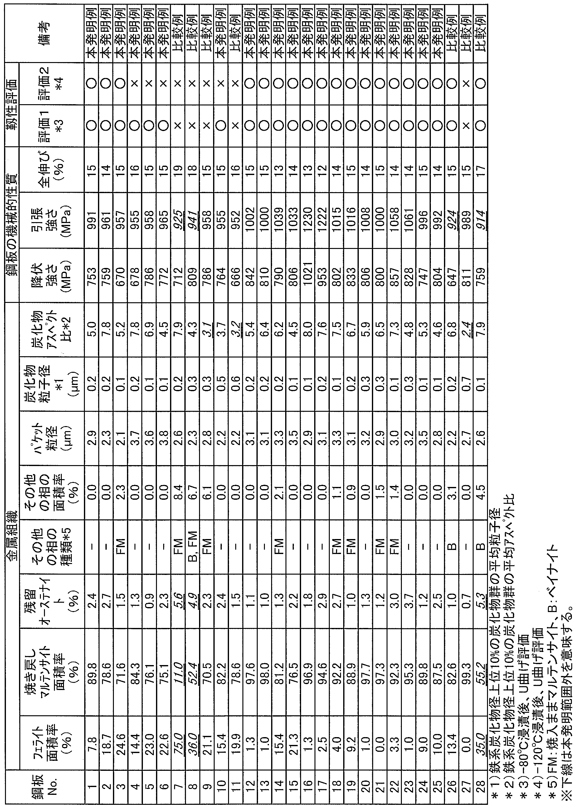
- Table 3 shows the average particle size.
- a packet is a group of variants having almost the same crystal habit plane (Reference 2: Goro Miyamoto, Samurai Kinoshita, Satoshi Kuchiba, Yasutada Furuhara, Sakai Metals Society of Japan, vol. 79, p. 339 (2015). .).
- the particle size of the iron-based carbide in the tempered martensite is determined by image analysis after determining the contour of the carbide using image analysis software (Image-Pro Plus ver.
- the equivalent circle diameter was determined.
- a histogram of individual equivalent circular diameters was created, and the average particle diameter and average aspect ratio were determined for the top 10% carbide groups with the largest particle diameters.
- the aspect ratio was obtained from (major axis length) / (minor axis length).
- an image scanning microscope image taken by the electron beam backscattering diffraction method (EBSD method) with the same number of photographing and magnification as the area ratio measurement conditions was used.
- EBSD method electron beam backscattering diffraction method
Landscapes
- Chemical & Material Sciences (AREA)
- Engineering & Computer Science (AREA)
- Mechanical Engineering (AREA)
- Materials Engineering (AREA)
- Metallurgy (AREA)
- Organic Chemistry (AREA)
- Physics & Mathematics (AREA)
- Thermal Sciences (AREA)
- Chemical Kinetics & Catalysis (AREA)
- Crystallography & Structural Chemistry (AREA)
- Oil, Petroleum & Natural Gas (AREA)
- Heat Treatment Of Sheet Steel (AREA)
Abstract
Description
本発明の薄鋼板は、特定の成分組成と、特定の金属組織とを有する。以下、成分組成、金属組織の順で説明する。
Cは、本発明鋼の主たる金属組織である焼き戻しマルテンサイトの硬度に関係し、鋼板の強度を上昇させるために有効な元素である。引張強さ:950MPa以上を得るには、少なくともC含有量を0.07%以上とする必要がある。一方、C含有量が0.20%を上回ると、残留オーステナイトが生成し、靱性が低下する。そのため、C含有量の範囲を0.07%以上0.20%以下とした。下限について好ましいC含有量は0.09%以上である。より好ましくは0.10%以上、さらに好ましくは0.12%以上である。上限について好ましいC含有量は0.19%以下である。より好ましくは0.17%以下、さらに好ましくは0.15%以下である。最も好ましくは0.14%以下である。
Siは、鉄系炭化物の粗大化を抑制するのに効果がある元素である。鉄系炭化物の粗大化を抑制することで靱性を良好なものとすることができる。この効果を得るには、少なくともSi含有量を0.01%以上にする必要がある。一方、Si含有量が2.0%を上回ると、化成処理性やめっき性への悪影響が顕在化し、自動車用部材として適用が困難となる。以上から、Si含有量範囲を0.01%以上2.0%以下とした。下限について好ましいSi含有量は0.05%以上である。より好ましくは0.10%以上、さらに好ましくは0.20%以上である。上限について好ましいSi含有量は1.65%以下である。より好ましくは1.60%以下、さらに好ましくは1.55%以下である。
Mnはフェライトからオーステナイトへの変態点を低下させ、本発明鋼の主たる金属組織である焼き戻しマルテンサイト生成を促す元素である。Mnによる所望の効果を得るためには、Mn含有量を1.8%以上にする必要がある。一方、Mn含有量が3.5%を上回ると、残留オーステナイトが過度に生成されるため、靱性が悪化する。そのため、Mn含有量は1.8%以上3.5%以下とした。下限について好ましいMn含有量は1.9%以上である。より好ましくは2.1%以上、さらに好ましくは2.3%以上である。上限について好ましいMn含有量は3.0%以下である。より好ましくは2.9%以下、さらに好ましくは2.8%以下である。
Pは、低温脆性を発生させる元素である。したがって、靱性の観点から、P含有量は極力低減することが好ましく、本発明では、P含有量は0.05%まで許容できる。好ましくは0.03%以下である。さらに好ましくは0.02%以下である。P含有量を極力低減する方が望ましいが、製造上、0.002%は不可避的に混入する場合がある。
Sは、鋼中で粗大な硫化物を形成し、これが熱間圧延時に伸展し楔状の介在物となることで、靱性に悪影響をもたらす。そのため、S含有量は極力低減することが好ましい。本発明では、S含有量は0.005%まで許容できるため、S含有量の上限を0.005%とした。好ましくは、0.003%以下である。さらに好ましくは0.002%以下である。S含有量は極力低減する方が望ましいが、製造上、0.0002%までは不可避的に混入する場合がある。
AlはSiと同様、鉄系炭化物の粗大化を抑制し、靱性改善に効果のある元素である。一方、2.0%を上回ると、粗大な酸化物生成により靱性に悪影響をもたらす。以上から、Al含有量は0.01%以上2.0%以下とした。下限について好ましいAl含有量は0.03%以上である。より好ましくは0.04%以上、さらに好ましくは0.05%以上である。上限について好ましいAl含有量は1.60%以下である。より好ましくは1.40%以下、さらに好ましくは1.20%以下である。また、所望の平均アスペクト比を得る観点から、SiとAlは合計で0.7%以上含有させる必要がある。好ましくは上記合計が0.8%以上である。より好ましくは上記合計が1.0%以上、さらに好ましくは1.2%以上である。また、上限について、上記合計は2.0%以下が好ましく、より好ましくは1.8%以下、さらに好ましくは1.6%以下である。
Nは、常温時効性を悪化させ曲げ加工時に予期せぬ割れを発生させる。そのため、N含有量は出来る限り低減することが望ましいが、本発明では0.0060%まで許容できる。好ましくは0.0050%以下である。さらに好ましくは0.0040%以下である。N含有量は極力低減する方が望ましいが、製造上、0.0005%は不可避的に混入する場合がある。
V、TiおよびNbは、Cと結合し微細な炭化物を形成することで鋼板の高強度化に寄与する元素である。一方、過度に含有させると粗大な炭化物として析出するため、靱性を悪化させる。以上の観点から、V:0.001%以上1%以下、Ti:0.001%以上0.3%以下、Nb:0.001%以上0.3%以下とした。下限について好ましいV含有量は0.005%以上である。より好ましくは0.050%以上である。さらに好ましくは0.100%以上である。上限について好ましいV含有量は0.6%以下である。より好ましくは0.5%以下、さらに好ましくは0.4%以下である。下限について好ましいTi含有量は0.005%以上である。より好ましくは0.010%以上、さらに好ましくは0.020%以上である。上限について好ましいTi含有量は0.1%以下である。より好ましくは0.08%以下、さらに好ましくは0.06%以下である。下限について好ましいNb含有量は0.005%以上である。より好ましくは0.010%以上、さらに好ましくは0.020%以上である。上限について好ましいNb含有量は0.1%以下である。より好ましくは0.08%以下、さらに好ましくは0.04%以下である。
Cr、MoおよびNiは鋼板の高強度化に寄与する元素である。一方、これらの元素を過度に添加すると、変態点が大きく変化することで所望の金属組織が得られなくなり、靱性が悪化する。Bは焼鈍後のマルテンサイト変態以外のフェライト変態やベイナイト変態進行を遅延させ、所望の金属組織を安定的に得るために効果のある元素である。Sbは表層に偏析することで脱炭を抑制し、表層組織の変質を防ぐ効果のある元素である。BやSbは過度に添加しても効果は飽和するため、添加元素の浪費につながる。以上の観点から、Cr:0.001%以上1.0%以下、Mo:0.001%以上1.0%以下、Ni:0.001%以上1.0%以下、B:0.0001%以上0.0050%以下、Sb:0.001%以上0.050%以下とした。下限について好ましいCr含有量は0.010%以上である。より好ましくは0.030%以上である。さらに好ましくは0.100%以上である。上限について好ましいCr含有量は0.8%以下である。より好ましくは0.7%以下、さらに好ましくは0.6%以下である。下限について好ましいMo含有量は0.010%以上である。より好ましくは0.030%以上、さらに好ましくは0.100%以上である。上限について好ましいMo含有量は0.6%以下である。より好ましくは0.5%以下、さらに好ましくは0.4%以下である。下限について好ましいNi含有量は0.010%以上である。より好ましくは0.020%以上、さらに好ましくは0.030%以上である。上限について好ましいNi含有量は0.5%以下である。より好ましくは0.3%以下、さらに好ましくは0.1%以下である。下限について好ましいB含有量は0.0003%以上である。より好ましくは0.0006%以上、さらに好ましくは0.0009%以上である。上限について好ましいB含有量は0.0030%以下である。より好ましくは0.0025%以下、さらに好ましくは0.0020%以下である。下限について好ましいSb含有量は0.005%以上である。より好ましくは0.006%以上、さらに好ましくは0.007%以上である。上限について好ましいSb含有量は0.030%以下である。より好ましくは0.020%以下、さらに好ましくは0.010%以下である。
REM、MgおよびCaは、鋼中の硫化物を球状化させることで靱性を向上させる元素である。一方、過度に添加しても効果は飽和するため、添加元素の浪費につながる。以上の観点から、REM、Mg、Caのいずれか1種または2種以上を合計で0.0001%以上0.1%以下とした。下限について好ましい合計含有量は0.0005%以上である。より好ましくは0.0010%以上である。上限について好ましい合計含有量は0.02%以下である。より好ましくは0.0050%以下である。
フェライトの生成によりMs点が減少することで焼き戻されていないマルテンサイト(焼入れままマルテンサイト)や残留オーステナイトが増加し、靱性に悪影響をもたらす。本発明鋼においてフェライト面積率30%までは許容できるため、上限を30%とした。好ましくは、25%以下である。より好ましくは22%以下、さらに好ましくは17%以下である。また、フェライト面積率は0%でもよいが、1%以上含むことも多い。また、3%以上含む場合もある。
焼き戻されたマルテンサイト(焼き戻しマルテンサイト)はラス構造を有するミクロ組織内部に鉄系の炭化物が析出した組織である。焼き戻しマルテンサイトは焼き戻されていないマルテンサイトよりも強度および靱性のバランスに優れる。そのため、本発明では、主たる金属組織として焼き戻しマルテンサイトを選択した。引張強さ950MPa以上を得るには、焼き戻しマルテンサイトは70%以上とする必要がある。好ましくは、75%以上である。より好ましくは80%以上、さらに好ましくは85%以上である。また、焼き戻しマルテンサイト面積率が100%でもよい。焼き戻しマルテンサイトは98%以下であることが多い。
粗大な炭化物は靱性に悪影響をもたらす。生成した鉄系炭化物の個々の粒子径を測定し、粒子径が上位10%の炭化物のアスペクト比(平均アスペクト比)が靱性に対し影響が大きい。この鉄系炭化物のアスペクト比が3.5以上であれば、所望の特性が得られる。好ましい上記アスペクト比は4.0以上である。より好ましくは4.5以上である。アスペクト比の上限は特に限定されないが、10.0以下や9.0以下であることが多い。また、上位10%の平均炭化物径は0.4μm以下とすることが好ましく、0.3μm以下がより好ましい。上記平均炭化物径の下限は特に限定されないが、0.05μm以上や0.1μm以上になることが多い。
残留オーステナイトは曲げ加工後の靱性を著しく低下させるため、可能な限り低減する必要がある。本発明鋼において残留オーステナイトは4.5%までは許容できる。好ましくは、3.8%以下である。より好ましくは4.0%以下、さらに好ましくは3.5%以下である。下限は0%まで含まれるが、実際には0.2%は生成することが多い。
Ms点(℃)=561-474×[C]/(1-Vf/100)-33×[Mn]-17×[Ni]-17×[Cr]-21×[Mo]・・・・・・・・・・・・・・・・・・・・・・・・・・・・・・・(1)
なお、(1)式中の元素記号は、各元素の含有量(質量%)を意味する。
次に、本発明の高強度めっき鋼板の製造方法について説明する。本発明の薄鋼板の製造方法は、鋼素材を、1150℃以上1350℃以下で加熱し、粗圧延と仕上げ圧延からなる熱間圧延を施すにあたり、820℃以上で仕上げ圧延終了後、350℃以上680℃以下で巻き取り(熱間圧延工程)、冷間圧延を施し(冷間圧延工程)、820℃以上で焼鈍した後、冷却開始温度からMs点までの平均冷却速度が20℃/s以上で冷却し、300℃から冷却停止温度である220℃以下までを平均冷却速度が12℃/s以下で冷却した後、加熱し、250℃以上440℃以下で30秒以上滞留させる(焼鈍工程)。
本発明においては、粗圧延に先立ち鋼素材を加熱して、鋼素材の金属組織を実質的に均質なオーステナイト相とする必要がある。また、粗大な介在物の生成を抑制するためには加熱温度の制御が重要となる。加熱温度が1150℃を下回ると所望の仕上げ完了圧延温度を得ることができない。一方、加熱温度が1350℃を上回ると、スケールロスが増大し、加熱炉の炉体への損傷が大きくなる。そのため、鋼素材の加熱温度は1150℃以上1350℃以下とした。望ましくは1180℃以上1320℃以下である。なお、上記加熱後の粗圧延の粗圧延条件については特に限定されない。
仕上げ圧延温度が820℃を下回ると、圧延中にオーステナイトからフェライトへの変態が開始してしまい、鋼板の局所的な強度が変動するため、次工程の冷間圧延の板厚精度が悪化する。そのため、仕上げ圧延温度は820℃以上とした。好ましくは840℃以上である。仕上げ圧延温度の上限は特に限定されないが、通常、1060℃以下である。
巻取温度が350℃を下回ると熱延板の形状が悪化し、冷間圧延後の板厚精度が悪化する。巻取温度が680℃を上回ると、熱延板表面に酸洗で除去しきれない酸化皮膜が生成し、冷延後の表面外観を損ねる。以上から、巻取温度の範囲を350℃以上680℃以下とした。好ましい下限は380℃以上である。好ましい上限は650℃以下である。
(1)式から、フェライトが焼鈍時に多量に残存した状態であると、Ms点が低下し所望の鋼板組織(金属組織)が得られなくなる。フェライトからオーステナイトへの変態を進行させる観点から、820℃以上で焼鈍する必要がある。好ましくは、830℃以上である。上限は特に設けないが、実質900℃以下である。また、焼戻しマルテンサイトのパケットサイズを小さくする観点から、加熱中転位の回復を抑制させながらフェライトからオーステナイトへ変態させることが望ましい。そのため、回復の影響が顕著となる400℃から700℃までの平均加熱速度は50℃/s以上とすることが望ましい。400℃から700℃までの平均加熱速度の上限は、特に限定されないが、通常、100℃/s以下である。また、オーステナイトの粒成長を抑制し上記パケットを微細化させつつ、フェライトからオーステナイトへ変態を促進させる観点から、700℃から最高到達温度までの平均加熱温度は、7℃/s以上とし、最高到達温度は焼鈍温度+10℃以上とし、最高到達温度以降は、20℃/s以上での冷却までの平均冷却速度が0.05℃/s以上で冷却することが好ましい。また、700℃から最高到達温度までの平均加熱温度は、通常、20℃/s以下である。また、最高到達温度は、通常、焼鈍温度+15℃以下である。また、20℃/s以上での冷却までの平均冷却速度は、通常、2.0℃/s以下である。ここで、焼鈍温度とは、焼鈍終了直後での温度とする。温度計の位置は、焼鈍炉出口から3m以内に温度計があることが好ましい。また、冷間圧延後の加熱条件である、加熱開始からの平均加熱速度等は特に限定されず、適宜設定すればよい。
オーステナイトからマルテンサイト変態させ、次工程以降で所望の焼き戻しマルテンサイトを生成させる必要があるため、本工程での冷却ではフェライト変態やベイナイト変態を抑制する必要がある。このため、冷却開始温度からMs点までの平均冷却速度は20℃/s以上で冷却する必要がある。好ましくは30℃/s以上である。また、上記平均冷却速度は、通常、300℃/s以下である。ここで冷却開始温度とは焼鈍の終了直後の温度である。また、本冷却において、冷却停止温度はMs点以下であればよく、通常140℃以上280℃以下である。
300℃から140℃までの温度域は鉄系炭化物がマルテンサイト中に顕著に析出する温度域である。本冷却で析出した鉄系炭化物は本発明で求めるアスペクト比の大きいものであるため、低温靱性を上昇させるために重要な工程となる。所望の組織を得るには、300℃から冷却停止までの平均冷却速度が12℃/s以下で冷却させる必要があり、好ましくは9℃/s以下である。また、上記平均冷却速度は、通常、1℃/s以上である。
上記冷却では、マルテンサイト変態をほぼ完了させ、残留オーステナイトをさせないようにするには、冷却停止温度は220℃以下とする必要がある。好ましくは200℃以下である。下限温度は特に設けないが、生産設備の制約上、120℃程度が下限である。
上記冷却後、加熱し、250℃以上440℃以下で30秒以上滞留させる。炭化物のアスペクト比を制御する等して、靱性を向上させる効果がある。所望の鋼板組織を得るには、250℃以上440℃以下で30秒以上滞留させる必要がある。好ましい滞留時間は250秒以下である。より好ましくは、330℃以上430℃以下で45秒以上200秒以下である。

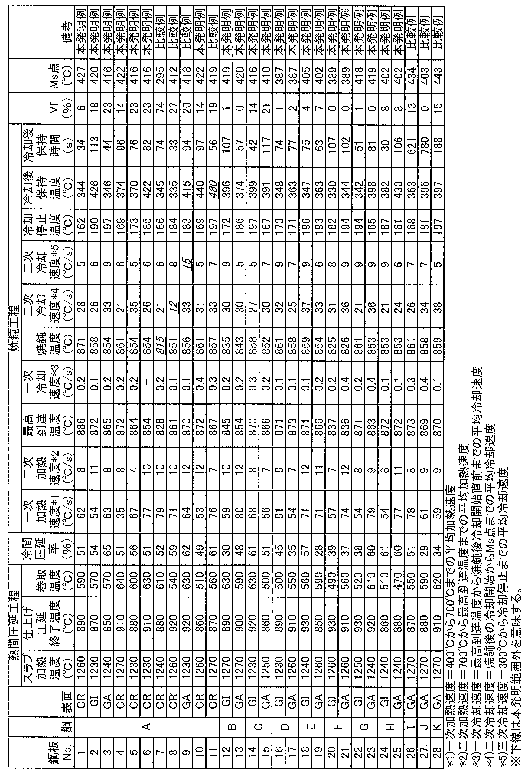
各相の面積率は以下の手法により評価した。鋼板から、圧延方向に平行な断面が観察面となるよう切り出し、板厚中心部を1%ナイタールで腐食現出し、走査電子顕微鏡で2000倍に拡大して鋼板表面から板厚方向に1/4t(tは厚み)位置を10視野分撮影した。フェライト相は粒内に腐食痕やセメンタイトが観察されない形態を有する組織であり、焼き戻しマルテンサイトは粒内に配向性を有する多数の微細なセメンタイトおよび腐食痕が認められる組織である。フェライト相、焼き戻しマルテンサイトとこれら以外の焼入ままマルテンサイト、ベイナイトといった組織の面積率を求め、結果を表3に示した。
得られた鋼板から圧延方向に対して垂直方向にJIS5号引張試験片を作製し、JIS Z 2241(2011)の規定に準拠した引張試験を5回行い、平均の降伏強さ(YS)、引張強さ(TS)、全伸び(El)を求めた。引張試験のクロスヘッドスピードは10mm/minとした。表3において、引張強さ:950MPa以上を本発明鋼で求める鋼板の機械的性質とした。
靭性の評価には、幅100mm、長さ35mmの端面研削加工した試験片を用い、(ポンチ半径)/(板厚)が3.0のV曲げ試験を行った。ストローク速度は50mm/minとし、最大荷重80kN、最大荷重保持時間を5秒とした。目視により曲げ稜線の欠陥有無を調査した。目視観察で割れが認められたものは不合格として「×」とした。なお、この曲げ試験の時点で割れが認められたのは、No.27であった。この曲げ試験後サンプルを用いて、-120℃もしくは-80℃の不凍液に5分浸漬し、ポンチ半径1.0mmでただちにU曲げ試験を行った。ポンチがサンプルに接触してから5mm押し込んだ時点で割れ(目視観察で判断)が生じなかったものは、本発明で求める靱性を持つ鋼板として「○」、脆性破壊した鋼板を不合格として「×」とし、結果を表3に示した。
Claims (10)
- 質量%で、
C:0.07%以上0.20%以下、
Si:0.01%以上2.0%以下、
Mn:1.8%以上3.5%以下、
P:0.05%以下、
S:0.005%以下、
Al:0.01%以上2.0%以下、
N:0.0060%以下、
Si+Al:0.7%以上、残部がFeおよび不可避的不純物からなる成分組成と、
フェライト面積率が30%以下(0%を含む)、焼き戻されたマルテンサイト面積率が70%以上(100%含む)、残留オーステナイト面積率が4.5%以下(0%を含む)であり、焼き戻されたマルテンサイト粒内に析出した鉄系炭化物の粒子径が大きい方から10%の鉄系炭化物の平均アスペクト比が3.5以上である金属組織とを有する薄鋼板。 - 前記成分組成は、さらに、質量%で、
V:0.001%以上1%以下、
Ti:0.001%以上0.3%以下、
Nb:0.001%以上0.3%以下の1種または2種以上を含有する請求項1に記載の薄鋼板。 - 前記成分組成は、さらに、質量%で、
Cr:0.001%以上1.0%以下、
Mo:0.001%以上1.0%以下、
Ni:0.001%以上1.0%以下、
B:0.0001%以上0.0050%以下、
Sb:0.001%以上0.050%以下の1種または2種以上を含有する請求項1または2に記載の薄鋼板。 - 前記成分組成は、さらに、質量%で、REM、Mg、Caのいずれか1種または2種以上を合計で0.0001%以上0.1%以下含有する請求項1~3のいずれかに記載の薄鋼板。
- 表面にめっき層を備える請求項1~4のいずれかに記載の薄鋼板。
- 前記めっき層の組成がFe:20.0%以下、Al:0.001%以上3.5%以下、Pb、Sb、Si、Sn、Mg、Mn、Ni、Cr、Co、Ca、Cu、Li、Ti、Be、Bi、REMから選択する1種または2種以上を合計:0%以上3.5%以下を含有し、残部がZn及び不可避不純物からなる請求項5に記載の薄鋼板。
- 前記めっき層が合金化溶融めっき層である請求項5または6に記載の薄鋼板。
- 請求項1から4のいずれかに記載の成分組成を有する鋼素材を、1150℃以上1350℃以下で加熱し、粗圧延と仕上げ圧延からなる熱間圧延を施すにあたり、820℃以上で仕上げ圧延終了後、350℃以上680℃以下で巻き取り、冷間圧延を施し、820℃以上で焼鈍した後、冷却開始温度からMs点までの平均冷却速度が20℃/s以上で冷却し、300℃から冷却停止温度である220℃以下までを平均冷却速度が12℃/s以下で冷却した後、加熱し、250℃以上440℃以下で30秒以上滞留させる薄鋼板の製造方法。
- 前記滞留後、めっき処理を施す請求項8に記載の薄鋼板の製造方法。
- 前記めっき処理は、前記滞留後の鋼板をめっき浴に浸漬させ、必要に応じて500℃以上600℃以下の合金化処理を施す処理である請求項9に記載の薄鋼板の製造方法。
Priority Applications (6)
| Application Number | Priority Date | Filing Date | Title |
|---|---|---|---|
| US16/324,970 US11220722B2 (en) | 2016-08-30 | 2017-08-29 | Steel sheet and method for manufacturing the same |
| EP17846458.2A EP3473741B1 (en) | 2016-08-30 | 2017-08-29 | Thin steel sheet and process for producing same |
| MX2019001828A MX2019001828A (es) | 2016-08-30 | 2017-08-29 | Lamina de acero y metodo para la fabricacion de la misma. |
| CN201780049491.0A CN109563592B (zh) | 2016-08-30 | 2017-08-29 | 薄钢板及其制造方法 |
| JP2017564150A JP6354919B1 (ja) | 2016-08-30 | 2017-08-29 | 薄鋼板およびその製造方法 |
| KR1020197004070A KR102186204B1 (ko) | 2016-08-30 | 2017-08-29 | 박강판 및 그의 제조 방법 |
Applications Claiming Priority (2)
| Application Number | Priority Date | Filing Date | Title |
|---|---|---|---|
| JP2016-168116 | 2016-08-30 | ||
| JP2016168116 | 2016-08-30 |
Publications (1)
| Publication Number | Publication Date |
|---|---|
| WO2018043453A1 true WO2018043453A1 (ja) | 2018-03-08 |
Family
ID=61305241
Family Applications (1)
| Application Number | Title | Priority Date | Filing Date |
|---|---|---|---|
| PCT/JP2017/030846 Ceased WO2018043453A1 (ja) | 2016-08-30 | 2017-08-29 | 薄鋼板およびその製造方法 |
Country Status (7)
| Country | Link |
|---|---|
| US (1) | US11220722B2 (ja) |
| EP (1) | EP3473741B1 (ja) |
| JP (1) | JP6354919B1 (ja) |
| KR (1) | KR102186204B1 (ja) |
| CN (1) | CN109563592B (ja) |
| MX (1) | MX2019001828A (ja) |
| WO (1) | WO2018043453A1 (ja) |
Cited By (8)
| Publication number | Priority date | Publication date | Assignee | Title |
|---|---|---|---|---|
| JP2020122213A (ja) * | 2019-01-29 | 2020-08-13 | Jfeスチール株式会社 | 高強度溶融亜鉛めっき鋼板およびその製造方法 |
| KR20210105419A (ko) * | 2019-01-29 | 2021-08-26 | 제이에프이 스틸 가부시키가이샤 | 고강도 용융 아연 도금 강판 및 그의 제조 방법 |
| WO2022019209A1 (ja) | 2020-07-20 | 2022-01-27 | 日本製鉄株式会社 | 鋼板及びその製造方法 |
| WO2022149502A1 (ja) | 2021-01-07 | 2022-07-14 | 日本製鉄株式会社 | 鋼板及びその製造方法 |
| JP2022532625A (ja) * | 2019-05-15 | 2022-07-15 | アルセロールミタル | 冷間圧延マルテンサイト鋼及びそのマルテンサイト鋼の方法 |
| US11427878B2 (en) * | 2019-10-12 | 2022-08-30 | Northeastern University | Ultrahigh-strength ultrahigh-toughness and low-density dual-phase lamellar steel plate and preparation method therefor |
| WO2023162573A1 (ja) | 2022-02-25 | 2023-08-31 | 日本製鉄株式会社 | 亜鉛めっき鋼板およびその製造方法 |
| JP2024500721A (ja) * | 2020-12-18 | 2024-01-10 | ポスコ カンパニー リミテッド | めっき密着性及び溶接性に優れた高強度溶融亜鉛めっき鋼板及びその製造方法 |
Families Citing this family (9)
| Publication number | Priority date | Publication date | Assignee | Title |
|---|---|---|---|---|
| KR102538733B1 (ko) * | 2018-12-18 | 2023-05-31 | 아르셀러미탈 | 내지연 파괴성이 높은 프레스 경화된 부분 및 그 제조 방법 |
| CA3163376C (en) * | 2019-12-13 | 2024-02-27 | Arcelormittal | Heat treated cold rolled steel sheet and a method of manufacturing thereof |
| CN115698365B (zh) * | 2020-07-20 | 2024-03-26 | 安赛乐米塔尔公司 | 经热处理的冷轧钢板及其制造方法 |
| KR102463731B1 (ko) * | 2020-11-25 | 2022-11-07 | 현대제철 주식회사 | 용융아연도금용 도금욕 및 이를 이용하여 형성한 용융아연도금 강판, 및 그 제조방법 |
| KR102366284B1 (ko) * | 2020-12-28 | 2022-02-23 | 현대제철 주식회사 | 핫 스탬핑 부품 및 그 제조방법 |
| KR102798279B1 (ko) * | 2022-09-16 | 2025-04-23 | 현대제철 주식회사 | 초고강도 냉연 강판 및 그 제조방법 |
| CN115627424B (zh) * | 2022-11-07 | 2023-08-18 | 鞍钢股份有限公司 | 一种1.5GPa级高塑性冷轧DH钢及其制备方法 |
| JP2026502075A (ja) | 2022-12-09 | 2026-01-21 | アルセロールミタル | 冷間圧延被覆鋼板及びその製造方法 |
| CN120330437B (zh) * | 2025-06-20 | 2025-08-22 | 太原科技大学 | 一种耐磨马氏体不锈钢及其制备方法 |
Citations (6)
| Publication number | Priority date | Publication date | Assignee | Title |
|---|---|---|---|---|
| JP2010132945A (ja) * | 2008-12-03 | 2010-06-17 | Nippon Steel Corp | 耐遅れ破壊特性および溶接性に優れる高強度厚鋼板およびその製造方法 |
| JP2012031466A (ja) * | 2010-07-30 | 2012-02-16 | Jfe Steel Corp | 高強度鋼板およびその製造方法 |
| WO2014077294A1 (ja) * | 2012-11-14 | 2014-05-22 | Jfeスチール株式会社 | 自動車用衝突エネルギー吸収部材およびその製造方法 |
| WO2014185405A1 (ja) * | 2013-05-14 | 2014-11-20 | 新日鐵住金株式会社 | 熱延鋼板およびその製造方法 |
| WO2016103534A1 (ja) * | 2014-12-22 | 2016-06-30 | Jfeスチール株式会社 | 高強度溶融亜鉛めっき鋼板およびその製造方法 |
| WO2016132680A1 (ja) * | 2015-02-17 | 2016-08-25 | Jfeスチール株式会社 | 高強度冷延薄鋼板およびその製造方法 |
Family Cites Families (16)
| Publication number | Priority date | Publication date | Assignee | Title |
|---|---|---|---|---|
| JPS5858199B2 (ja) | 1981-05-02 | 1983-12-23 | 株式会社 福山織機製作所 | 畳縫着機用畳床裁断装置 |
| CA2433626C (en) * | 2000-12-29 | 2009-12-08 | Nippon Steel Corporation | High strength hot-dip galvanized or galvannealed steel sheet having improved plating adhesion and press formability and process for producing the same |
| EP2465962B1 (en) | 2006-07-14 | 2013-12-04 | Kabushiki Kaisha Kobe Seiko Sho | High-strength steel sheets and processes for production of the same |
| WO2009066734A1 (ja) | 2007-11-22 | 2009-05-28 | Kabushiki Kaisha Kobe Seiko Sho | 高強度冷延鋼板 |
| JP5365216B2 (ja) * | 2008-01-31 | 2013-12-11 | Jfeスチール株式会社 | 高強度鋼板とその製造方法 |
| JP5365217B2 (ja) * | 2008-01-31 | 2013-12-11 | Jfeスチール株式会社 | 高強度鋼板およびその製造方法 |
| KR101230803B1 (ko) | 2008-03-07 | 2013-02-06 | 가부시키가이샤 고베 세이코쇼 | 냉간 압연 강판 |
| WO2010109702A1 (ja) | 2009-03-27 | 2010-09-30 | 株式会社神戸製鋼所 | 冷延鋼板 |
| JP5418047B2 (ja) * | 2008-09-10 | 2014-02-19 | Jfeスチール株式会社 | 高強度鋼板およびその製造方法 |
| CN103842545A (zh) * | 2011-09-28 | 2014-06-04 | 杰富意钢铁株式会社 | 高强度钢板及其制造方法 |
| JP5728108B2 (ja) | 2013-09-27 | 2015-06-03 | 株式会社神戸製鋼所 | 加工性および低温靭性に優れた高強度鋼板、並びにその製造方法 |
| JP5728115B1 (ja) | 2013-09-27 | 2015-06-03 | 株式会社神戸製鋼所 | 延性および低温靭性に優れた高強度鋼板、並びにその製造方法 |
| EP3054025B1 (en) | 2013-12-18 | 2018-02-21 | JFE Steel Corporation | High-strength galvanized steel sheet and method for manufacturing the same |
| JP6354268B2 (ja) | 2014-04-02 | 2018-07-11 | 新日鐵住金株式会社 | 打抜き穴広げ性と低温靭性に優れた引張最大強度980MPa以上の高強度熱延鋼板及びその製造方法 |
| JP5958666B1 (ja) * | 2014-12-22 | 2016-08-02 | Jfeスチール株式会社 | 高強度溶融亜鉛めっき鋼板およびその製造方法 |
| EP3279353B1 (en) * | 2015-04-01 | 2019-03-27 | JFE Steel Corporation | Hot-rolled steel sheet and method for producing same |
-
2017
- 2017-08-29 WO PCT/JP2017/030846 patent/WO2018043453A1/ja not_active Ceased
- 2017-08-29 MX MX2019001828A patent/MX2019001828A/es unknown
- 2017-08-29 EP EP17846458.2A patent/EP3473741B1/en active Active
- 2017-08-29 KR KR1020197004070A patent/KR102186204B1/ko active Active
- 2017-08-29 CN CN201780049491.0A patent/CN109563592B/zh active Active
- 2017-08-29 US US16/324,970 patent/US11220722B2/en active Active
- 2017-08-29 JP JP2017564150A patent/JP6354919B1/ja active Active
Patent Citations (6)
| Publication number | Priority date | Publication date | Assignee | Title |
|---|---|---|---|---|
| JP2010132945A (ja) * | 2008-12-03 | 2010-06-17 | Nippon Steel Corp | 耐遅れ破壊特性および溶接性に優れる高強度厚鋼板およびその製造方法 |
| JP2012031466A (ja) * | 2010-07-30 | 2012-02-16 | Jfe Steel Corp | 高強度鋼板およびその製造方法 |
| WO2014077294A1 (ja) * | 2012-11-14 | 2014-05-22 | Jfeスチール株式会社 | 自動車用衝突エネルギー吸収部材およびその製造方法 |
| WO2014185405A1 (ja) * | 2013-05-14 | 2014-11-20 | 新日鐵住金株式会社 | 熱延鋼板およびその製造方法 |
| WO2016103534A1 (ja) * | 2014-12-22 | 2016-06-30 | Jfeスチール株式会社 | 高強度溶融亜鉛めっき鋼板およびその製造方法 |
| WO2016132680A1 (ja) * | 2015-02-17 | 2016-08-25 | Jfeスチール株式会社 | 高強度冷延薄鋼板およびその製造方法 |
Cited By (20)
| Publication number | Priority date | Publication date | Assignee | Title |
|---|---|---|---|---|
| KR102500089B1 (ko) * | 2019-01-29 | 2023-02-14 | 제이에프이 스틸 가부시키가이샤 | 고강도 용융 아연 도금 강판 및 그의 제조 방법 |
| KR20210105419A (ko) * | 2019-01-29 | 2021-08-26 | 제이에프이 스틸 가부시키가이샤 | 고강도 용융 아연 도금 강판 및 그의 제조 방법 |
| EP3901293A4 (en) * | 2019-01-29 | 2022-01-05 | JFE Steel Corporation | HIGH STRENGTH HOT-GALVANIZED STEEL SHEET AND MANUFACTURING PROCESS FOR IT |
| US11643701B2 (en) | 2019-01-29 | 2023-05-09 | Jfe Steel Corporation | High-strength hot-dip galvanized steel sheet and manufacturing method therefor |
| JP7056631B2 (ja) | 2019-01-29 | 2022-04-19 | Jfeスチール株式会社 | 高強度溶融亜鉛めっき鋼板およびその製造方法 |
| JP2020122213A (ja) * | 2019-01-29 | 2020-08-13 | Jfeスチール株式会社 | 高強度溶融亜鉛めっき鋼板およびその製造方法 |
| JP2022532625A (ja) * | 2019-05-15 | 2022-07-15 | アルセロールミタル | 冷間圧延マルテンサイト鋼及びそのマルテンサイト鋼の方法 |
| JP7827756B2 (ja) | 2019-05-15 | 2026-03-10 | アルセロールミタル | 冷間圧延マルテンサイト鋼及びそのマルテンサイト鋼の方法 |
| JP2024045307A (ja) * | 2019-05-15 | 2024-04-02 | アルセロールミタル | 冷間圧延マルテンサイト鋼及びそのマルテンサイト鋼の方法 |
| US11427878B2 (en) * | 2019-10-12 | 2022-08-30 | Northeastern University | Ultrahigh-strength ultrahigh-toughness and low-density dual-phase lamellar steel plate and preparation method therefor |
| KR20230012028A (ko) | 2020-07-20 | 2023-01-25 | 닛폰세이테츠 가부시키가이샤 | 강판 및 그 제조 방법 |
| US12305258B2 (en) | 2020-07-20 | 2025-05-20 | Nippon Steel Corporation | Steel sheet and manufacturing method thereof |
| WO2022019209A1 (ja) | 2020-07-20 | 2022-01-27 | 日本製鉄株式会社 | 鋼板及びその製造方法 |
| JP7684402B2 (ja) | 2020-12-18 | 2025-05-27 | ポスコ カンパニー リミテッド | めっき密着性及び溶接性に優れた高強度溶融亜鉛めっき鋼板及びその製造方法 |
| JP2024500721A (ja) * | 2020-12-18 | 2024-01-10 | ポスコ カンパニー リミテッド | めっき密着性及び溶接性に優れた高強度溶融亜鉛めっき鋼板及びその製造方法 |
| WO2022149502A1 (ja) | 2021-01-07 | 2022-07-14 | 日本製鉄株式会社 | 鋼板及びその製造方法 |
| US12173380B2 (en) | 2021-01-07 | 2024-12-24 | Nippon Steel Corporation | Steel sheet and method for producing same |
| KR20230086778A (ko) | 2021-01-07 | 2023-06-15 | 닛폰세이테츠 가부시키가이샤 | 강판 및 그 제조 방법 |
| KR20240144265A (ko) | 2022-02-25 | 2024-10-02 | 닛폰세이테츠 가부시키가이샤 | 아연 도금 강판 및 그 제조 방법 |
| WO2023162573A1 (ja) | 2022-02-25 | 2023-08-31 | 日本製鉄株式会社 | 亜鉛めっき鋼板およびその製造方法 |
Also Published As
| Publication number | Publication date |
|---|---|
| KR20190028750A (ko) | 2019-03-19 |
| US11220722B2 (en) | 2022-01-11 |
| KR102186204B1 (ko) | 2020-12-03 |
| EP3473741B1 (en) | 2020-05-13 |
| EP3473741A4 (en) | 2019-05-15 |
| CN109563592A (zh) | 2019-04-02 |
| CN109563592B (zh) | 2021-02-19 |
| MX2019001828A (es) | 2019-06-06 |
| EP3473741A1 (en) | 2019-04-24 |
| US20190185954A1 (en) | 2019-06-20 |
| JPWO2018043453A1 (ja) | 2018-08-30 |
| JP6354919B1 (ja) | 2018-07-11 |
Similar Documents
| Publication | Publication Date | Title |
|---|---|---|
| JP6354919B1 (ja) | 薄鋼板およびその製造方法 | |
| CN111511945B (zh) | 高强度冷轧钢板及其制造方法 | |
| KR102002737B1 (ko) | 고강도 강판용 소재, 고강도 강판용 열연재, 고강도 강판용 열연 소둔재, 고강도 강판, 고강도 용융 도금 강판 및 고강도 전기 도금 강판과, 이들의 제조 방법 | |
| US8657969B2 (en) | High-strength galvanized steel sheet with excellent formability and method for manufacturing the same | |
| JP6296214B1 (ja) | 薄鋼板およびその製造方法 | |
| WO2016129214A1 (ja) | 高強度溶融亜鉛めっき鋼板及びその製造方法 | |
| JP6274360B2 (ja) | 高強度亜鉛めっき鋼板、高強度部材及び高強度亜鉛めっき鋼板の製造方法 | |
| CN104114729B (zh) | 冷轧钢板、镀敷钢板和它们的制造方法 | |
| WO2016067623A1 (ja) | 高強度鋼板、高強度溶融亜鉛めっき鋼板、高強度溶融アルミニウムめっき鋼板および高強度電気亜鉛めっき鋼板、ならびに、それらの製造方法 | |
| JP6384623B2 (ja) | 高強度鋼板およびその製造方法 | |
| WO2018030503A1 (ja) | 薄鋼板およびその製造方法 | |
| CN115151673B (zh) | 钢板、构件和它们的制造方法 | |
| CN115151672A (zh) | 钢板、构件和它们的制造方法 | |
| US11365459B2 (en) | High strength cold rolled steel sheet and method of producing same | |
| JP2016188395A (ja) | 溶接性と加工性に優れた高強度冷延鋼板とその製造方法 | |
| CN108713066B (zh) | 高强度钢板及其制造方法 | |
| CN115210398B (zh) | 钢板、构件和它们的制造方法 | |
| US20190106759A1 (en) | Steel sheet, coated steel sheet, method for producing hot-rolled steel sheet, method for producing full hard cold-rolled steel sheet, method for producing steel sheet, and method for producing coated steel sheet | |
| WO2016157257A1 (ja) | 高強度鋼板およびその製造方法 | |
| JP5434984B2 (ja) | 引張強度440MPa以上の加工性に優れた高強度溶融亜鉛めっき鋼板およびその製造方法 | |
| CN114585759A (zh) | 高强度钢板和碰撞吸收构件以及高强度钢板的制造方法 | |
| KR101968434B1 (ko) | 고강도 도금 강판 및 그 제조 방법 | |
| CN114585758B (zh) | 高强度钢板和碰撞吸收构件以及高强度钢板的制造方法 |
Legal Events
| Date | Code | Title | Description |
|---|---|---|---|
| WWE | Wipo information: entry into national phase |
Ref document number: 2017564150 Country of ref document: JP |
|
| 121 | Ep: the epo has been informed by wipo that ep was designated in this application |
Ref document number: 17846458 Country of ref document: EP Kind code of ref document: A1 |
|
| ENP | Entry into the national phase |
Ref document number: 2017846458 Country of ref document: EP Effective date: 20190115 |
|
| ENP | Entry into the national phase |
Ref document number: 20197004070 Country of ref document: KR Kind code of ref document: A |
|
| NENP | Non-entry into the national phase |
Ref country code: DE |