WO2018047342A1 - モータ制御装置及び電動パワーステアリング制御装置 - Google Patents
モータ制御装置及び電動パワーステアリング制御装置 Download PDFInfo
- Publication number
- WO2018047342A1 WO2018047342A1 PCT/JP2016/076813 JP2016076813W WO2018047342A1 WO 2018047342 A1 WO2018047342 A1 WO 2018047342A1 JP 2016076813 W JP2016076813 W JP 2016076813W WO 2018047342 A1 WO2018047342 A1 WO 2018047342A1
- Authority
- WO
- WIPO (PCT)
- Prior art keywords
- motor
- control device
- shield plate
- motor case
- disposed
- Prior art date
- Legal status (The legal status is an assumption and is not a legal conclusion. Google has not performed a legal analysis and makes no representation as to the accuracy of the status listed.)
- Ceased
Links
Images



Classifications
-
- H—ELECTRICITY
- H02—GENERATION; CONVERSION OR DISTRIBUTION OF ELECTRIC POWER
- H02K—DYNAMO-ELECTRIC MACHINES
- H02K11/00—Structural association of dynamo-electric machines with electric components or with devices for shielding, monitoring or protection
- H02K11/30—Structural association with control circuits or drive circuits
- H02K11/33—Drive circuits, e.g. power electronics
-
- H—ELECTRICITY
- H02—GENERATION; CONVERSION OR DISTRIBUTION OF ELECTRIC POWER
- H02K—DYNAMO-ELECTRIC MACHINES
- H02K11/00—Structural association of dynamo-electric machines with electric components or with devices for shielding, monitoring or protection
- H02K11/01—Structural association of dynamo-electric machines with electric components or with devices for shielding, monitoring or protection for shielding from electromagnetic fields, i.e. structural association with shields
- H02K11/014—Shields associated with stationary parts, e.g. stator cores
- H02K11/0141—Shields associated with casings, enclosures or brackets
-
- H—ELECTRICITY
- H02—GENERATION; CONVERSION OR DISTRIBUTION OF ELECTRIC POWER
- H02K—DYNAMO-ELECTRIC MACHINES
- H02K11/00—Structural association of dynamo-electric machines with electric components or with devices for shielding, monitoring or protection
- H02K11/30—Structural association with control circuits or drive circuits
-
- H—ELECTRICITY
- H02—GENERATION; CONVERSION OR DISTRIBUTION OF ELECTRIC POWER
- H02K—DYNAMO-ELECTRIC MACHINES
- H02K5/00—Casings; Enclosures; Supports
- H02K5/04—Casings or enclosures characterised by the shape, form or construction thereof
- H02K5/10—Casings or enclosures characterised by the shape, form or construction thereof with arrangements for protection from ingress, e.g. water or fingers
-
- H—ELECTRICITY
- H02—GENERATION; CONVERSION OR DISTRIBUTION OF ELECTRIC POWER
- H02K—DYNAMO-ELECTRIC MACHINES
- H02K9/00—Arrangements for cooling or ventilating
- H02K9/22—Arrangements for cooling or ventilating by solid heat conducting material embedded in, or arranged in contact with, the stator or rotor, e.g. heat bridges
- H02K9/227—Heat sinks
Definitions
- the present invention relates to a motor control device and an electric power steering control device, and more particularly to a noise control of a control unit in a motor control device and an electric power steering control device in which a motor and a control unit are integrated.
- the motor has a stator winding
- the control unit has an inverter circuit for controlling the current flowing through the winding
- the control unit is disposed on the output shaft of the motor
- a control unit is disposed on the side opposite to the output side of the motor output shaft, and a plurality of connectors and components of the power supply circuit section are mounted on a connector case that covers the control unit. It is. Accordingly, the power supply circuit portion, which is a relatively large component, is arranged separately from the control unit without being arranged in the control unit, thereby reducing the size of the electronic control device.
- Each component (capacitor, coil) of the power circuit section is connected to a power conductive bar extending from the power connector, and is effective for noise emission to the outside of the electronic control device by the power circuit section. .
- control board in the control unit performs high-current PWM control of the inverter circuit, noise is emitted to the outside, and such noise emission still has to be improved.
- the present invention has been made to solve the above-described problems, and an object of the present invention is to provide a motor control device and an electric power steering control device in which noise emission from the control unit is suppressed.
- a motor case with a built-in motor a housing for mounting a power connector and covering an upper portion of the motor case, the motor case and the housing,
- a motor control device having a shield plate is provided.
- the present invention provides an electric power steering control device that includes the motor control device and generates a steering assist torque by the motor.
- the control unit in the motor control device in which the motor and the control unit are integrated, includes a filter unit connected to the power connector and a control board on which circuit components for supplying current to the motor are mounted. Since the shield plate grounded to the motor case is provided in between, there is an effect that the shield plate can suppress emission of noise generated from the circuit components of the control board to the outside.
- FIG. 1 is an overall electric circuit diagram in a first embodiment common to a motor control device and an electric power steering control device according to the present invention.
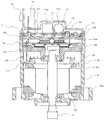
- FIG. 1 is a cross-sectional view showing an overall mechanical configuration in a first embodiment common to a motor control device and an electric power steering control device according to the present invention. It is a top view of the filter part periphery in Embodiment 1 common to the motor control apparatus and electric power steering control apparatus which concern on this invention. It is sectional drawing which showed the whole machine structure in Embodiment 2 and 3 common to the motor control apparatus and electric power steering control apparatus which concern on this invention.
- Embodiment 1 FIG. 1 showing an electric system common to the motor control device and the electric power steering control device according to Embodiment 1 of the present invention
- the control unit 1 mainly includes an inverter circuit 3 for supplying current to the motor 2 and a CPU 10.
- the motor 1 is used for an electric power steering operation, for example.
- a power source + B (battery power line) and GND (ground line) are connected to the filter unit 17 from a battery 6 mounted on the vehicle, and power is turned on by the ignition switch 7 via the power circuit 13 of the control circuit unit 4.
- sensors 8 including a torque sensor (not shown) for detecting a steering torque mounted in the vicinity of the steering wheel, a speed sensor for detecting the traveling speed of the vehicle, and the like are provided.
- the power source from the power source circuit 13 via the filter unit 17 and the power relay switching element 5 becomes a current source of the inverter circuit 3.
- the filter unit 17 includes a common mode coil 17b, a normal mode coil 17d, and capacitors 17a, 17c, 17e1, and 17e2. Depending on the noise generated by the device, either of the coils 17b and 17d may be used. Only one of them may be used, and the number of capacitors can be deleted.
- Information from the sensors 8 is transmitted to the CPU 10 via the input circuit 12 of the control circuit unit 4.
- the CPU 10 calculates and outputs a control amount corresponding to the current for rotating the motor 2 from the information.
- the output signal of the CPU 10 is transmitted to the drive circuit 11 and the inverter circuit 3 that constitute the output circuit.
- the drive circuit 11 receives a command signal from the CPU 10 and outputs a drive signal for driving each switching element of the inverter circuit 3.
- the drive circuit 11 is arranged in the control circuit unit 4 because only a small current flows, but may be arranged in the inverter circuit 3.
- the inverter circuit 3 mainly includes upper and lower arm switching elements 31U, 31V, 31W (hereinafter, may be collectively referred to as reference numeral 31) and 32U for the three-phase windings (U, V, W) of the motor 2. , 32V, 32W (hereinafter sometimes collectively referred to as reference numeral 32) and motor relay switching elements 34U, 34V, 34W (hereinafter collectively referred to as reference numeral 34) for connecting / disconnecting the wiring with the motor winding.
- Current detection shunt resistors 33U, 33V, 33W hereinafter sometimes collectively referred to as reference numeral 33
- noise suppression capacitors 30U, 30V, 30W hereinafter, generally referred to as reference numeral 30. There are some cases.)
- Each phase winding has the same circuit configuration, and current can be supplied to each phase winding independently.
- the potential difference between both ends of the shunt resistor 33 and the winding terminal voltage of the motor 2 are also fed back to the input circuit 12. These pieces of information are also input to the CPU 10, and by calculating a difference from the detected value corresponding to the calculated current value and performing feedback control, a desired motor current is supplied to assist the steering force.
- the drive circuit 11 also outputs a drive signal for the switching element 5 for power relay that operates as a relay for connecting / disconnecting the battery + B line and the power line of the inverter circuit 3.
- the current supply to itself can be cut off.
- the motor relay switching element 34 is also disposed in the inverter circuit 3 and can block each phase. Since the switching element 5 for power relay also flows with a large current and generates heat, it may be included in the inverter circuit 3.
- the CPU 10 has an abnormality detection function for detecting an abnormality in the drive circuit 11, the inverter circuit 3, the motor winding, and the like.
- an abnormality for example, only a predetermined phase is detected according to the abnormality.
- the switching elements 31 and 32 or the motor relay switching element 34 of the phase are turned off. Further, in order to cut off the entire current, the power relay switching element 5 can be turned off so as to cut off the power supply itself.
- the motor 2 is a brushless motor in which three-phase windings are star-connected. Since it is a brushless motor, a rotation sensor 9 for detecting the rotational position of the rotor is mounted. The rotation information is also fed back to the input circuit 12. Instead of a brushless motor with a three-phase star connection, a delta connection or a two-pole two-pair brushed motor may be used. Moreover, the winding specification can adopt distributed winding or concentrated winding as in the conventional apparatus.
- a filter unit 17 is inserted so that so-called switching noise due to PWM control of the control unit 1, particularly the inverter circuit 3, is not transmitted from the apparatus to the outside.
- the coil 17b is for common mode noise and is called a common mode coil
- the coil 17d is for normal mode noise and is called a normal mode coil.
- the capacitors 17a and 17c are called across-the-line capacitors or X capacitors, and the capacitors 17e1 and 17e2 are called line bypass capacitors or Y capacitors. These filter elements suppress conduction noise and radiation noise, and are called EMI (Electromagnetic Interference) filters.
- a midpoint 17f between the capacitors of the Y capacitor 17e is a body ground, and is electrically connected to the vehicle body via a part of the apparatus and grounded.
- FIG. 2 The structure of FIG. 2 in which the motor 2 and the control unit 1 common to the motor control device and the electric power steering control device having the above electric circuit are integrated will be described below.
- the motor 2 is arranged on the lower side of FIG. 2, the control unit 1 is arranged on the upper side, and both are integrated on the same axis of the motor output shaft 21.
- the motor 2 is housed in a motor case 25 as in the conventional device, and a rotor 23 in which a plurality of permanent magnets are arranged around the output shaft 21 and a winding 24 is wound around the rotor 23 with a gap.
- the stator 22 is arranged.
- the winding 24 is wound around each of the three phases, and an end of each phase is provided with an annular connection ring 27 in the vicinity of the winding for connection, and the end of the three-phase winding is extended.
- Three of the winding end portions 26 extend to the control unit 1.
- a frame 28 is provided at the boundary between the control unit 1 and the motor 2, and a hole is formed at the center thereof through which the motor output shaft 21 and the winding end portion 26 can pass while holding the bearing.
- the control unit 1 incorporates a control board 4a on which the inverter circuit 3, the control circuit unit 4, and the power relay switching element 5 shown in FIG. 1 are mounted.
- the upper part of the control unit 1 is covered with a housing 40, and a filter chamber 41 having a convex cross section is formed in which the filter portion 17 composed of the coils 17b and 17d is accommodated in the approximate center of the housing 40.
- a power connector 42 is disposed in the vicinity of the filter chamber 41 and on the outermost part of the housing 40.
- the power connector 42, the housing 40, and the upper portion of the filter chamber 41 are integrally formed of a resin material.
- the control board 4a is mounted with circuit components for supplying current to the motor 2 such as the control circuit unit 4 and the inverter circuit 3 in FIG.
- the power modules 35a and 35b (hereinafter referred to as reference numeral 35 shown in FIG. 1) in which the CPU 10 is mounted on the upper surface and the switching elements 31, 32, 34 (see FIG. 1) and the like are mounted on the lower surface may be collectively referred to. .) Is arranged.
- the power module 35 incorporates an inverter circuit for one phase of the winding 24 and is arranged for three phases (only two of 35a and 35b are shown in FIG. 2).
- the power modules 35 a and 35 b that supply current to the winding 24 of the motor 2 generate heat by being controlled, and are in contact with the frame 28 so that heat can be transferred. Therefore, the frame 28 also serves as a heat sink.
- the winding end 26 is connected to a wiring pattern or a terminal (both not shown) of the control board 4a.
- the filter unit 17 built in the filter chamber 41 is composed of the components shown in FIG. 1, but only the coils 17b and 17d, which are large components, are shown in FIG.
- the filter portion 17 and the power supply conductive lines (+ B and GND lines) extending from the terminal 44 of the power supply connector 42 are integrally held by an insulating resin member 43. Further, the terminals of the coils 17b and 17d and the capacitors 17a, 17c, 17e1 and 17e2 are connected to the power supply conductive lines.
- the control board 4a including main components such as the power modules 35a and 35b of the control unit 1, particularly the inverter circuit 3, is housed in the motor case 25.
- the motor case 25 is made of metal, particularly aluminum. Further, the motor case 25 is provided with an attachment portion 25a for attachment to the vehicle body. An electrical body ground is formed by fixing the attachment portion 25a and the vehicle body with bolts or the like.
- the housing 40 is preferably made of resin in order to have the power connector 42 and the like, but a measure for suppressing noise emission from the control board 4a is necessary in this region. Therefore, the metal shield plate 50 is disposed between the control board 4 a and the lower surface of the housing 40.
- the shield plate 50 has a substantially circular shape, and its periphery abuts against the motor case 25. As a result, the shield plate 50 is electrically connected, and the shield plate 50 is body-grounded. Become a shape. For this reason, the degree of suppression of noise emission is improved.
- a part of the lower surface of the shield plate 50 is in contact with, for example, the CPU 10 mounted on the control board 4a as shown in FIG.
- This contact structure also improves the heat dissipation of the CPU 10. Heat in this case is transmitted from the upper surface of the CPU 10 to the outside through the shield plate 50 from the motor case 25.
- the outer periphery of the control unit 1 is surrounded by the metal motor case 25, and the shield plate 50 is disposed between the housing 40 and the noise emission can be suppressed. Further, the shield plate 50 is electrically connected to the motor case 25, and has a structure that improves heat dissipation by contacting the shield plate 50 with a control circuit component.
- Embodiment 2 will be described with reference to FIG. Parts equivalent to those in the first embodiment are denoted by the same reference numerals.
- 3 shows the housing 40 omitted so that the upper surface of the shield plate 50 can be seen.
- the resin member 43 has a role of fixing the resin member 43 on the upper surface of the shield plate 50, and has four holes 50a for screw tightening as shown. Further, in the portion facing the connecting portion between the filter portion 17 and the conductive wire in the resin member 43, the recesses 50e and 50f are provided so as not to directly contact each other. Furthermore, a hole through which a plurality of terminal ends of the terminal 44 of the power supply connector 42 passes is also formed. That is, the holes 50 b and 50 c are terminal through holes of a connector for the sensors 8.
- the hole 50 d is a hole through which a conductive wire for power supply that extends from the terminal 44 of the power supply connector 42 and passes through the filter unit 17.
- the shield plate 50 has a plurality of holes. However, compared to the shield plate 50 having no holes, it is difficult to design a small hole with no difference in noise emission suppression surfaces. Absent.
- an outer peripheral wall 51 made of, for example, resin or rubber is provided near the outer periphery of the shield plate 50.
- the outer peripheral edge of the housing 40 can be inserted into the outer peripheral wall 51 and used for fixing the housing 40.
- a waterproof rubber packing 52 (see FIG. 4) is disposed on the outer peripheral wall 51 and the inner wall of the motor case 25, or waterproofing is ensured with the outer peripheral edge of the housing by applying a sealant. Is also possible.
- the outer periphery of the control unit 1 is surrounded by the metal motor case 25, and the shield plate 50 is disposed between the housing 40 and the noise emission can be suppressed. Further, there is an effect that the shield plate 50 can be easily used for electrical connection with the motor case 25, fixing of the resin member 43, and ensuring the waterproofness of the control unit 1.
- Embodiment 3 will be described with reference to FIG.
- symbol is attached
- the difference between the third embodiment and the second embodiment shown in FIG. 2 is a case for the motor case and the control unit 1. That is, the motor case 225 incorporating the motor 2 is made of, for example, an iron-based material, and the rotor 23, the motor output shaft 21, the stator 22 and the like are similarly held therein.
- the attachment part 225a with the vehicle body is configured separately from the motor case 225, and both are fixed by a plurality of bolts. Therefore, mechanical and electrical connection with the vehicle body can be ensured by contacting the motor case 225.
- the control unit 1 is accommodated in a case-like frame 228 forming the outer layer, and the upper part is covered with a lid-like housing 400. That is, the frame 228 has an upper concave portion and a lower concave portion which are internal spaces, and has a structure in which most of the various electronic components of the control unit 1 are built in the upper concave portion.
- the lower concave portion of the frame 228 is in contact with the upper outer wall of the motor case 225 and is mechanically and electrically connected to the motor 2.
- the motor output shaft 21 penetrates through the frame 228 in the center, and the winding end 26 of the motor 2 penetrates through the periphery. Further, the power modules 35 a and 35 b are in contact with the upper surface of the upper concave portion of the frame 228. Further, although not shown, a part of the frame 228 has a recess, and a plurality of capacitors 30 shown in the circuit of FIG. 1 are separately accommodated in the recess.
- control board 4a is disposed on the upper part of the recess of the frame 228, the shield plate 500 is disposed on the upper part thereof, and further, an attachment part with the housing 400 is provided around.
- a part of the shield plate 500 is brought into contact with an electronic component of the control board 4a, for example, the CPU 10, thereby improving heat dissipation of the electronic component.
- the periphery of the shield plate 500 is electrically and mechanically connected and fixed by contacting the inner periphery of the frame 228.
- the housing 400 accommodates a coil 17b and the like which are a part of the filter unit 17 shown in FIG. 1, and has a power connector 42 at the upper part.
- the electrical connection between the power supply connector 42 and the filter unit 17 is performed by the resin member 43 and the substrate 45 containing the conductive wires.
- the legs of the coil 17b and the terminals of the power connector 42 are connected to conductive wires fixed by a resin member 43.
- the capacitors 17a, 17c, 17e1 and 17e2 shown in FIG. Has been.
- several terminals are each extended to the power supply system terminal for control board 4a and power module 35a, 35b.
- the shield plate 500 is provided with a recess, and further, holes for a plurality of terminals. In particular, since the holes are formed as small holes in a part of the shield plate 500, it does not affect the performance of the shield.
- the frame 228 has a concave portion on the lower side in addition to the concave portion on the upper side, and the inner peripheral portion of the upper concave portion is in close contact with the housing 400 and the shield plate 500, respectively.
- the inner periphery of the motor is in close contact with the motor case 225.
- waterproofness can be ensured by inserting a waterproof structure, for example, packing 52a, in part at the contact portion between the frame 228 and the motor case 225.
- a waterproof structure for example, packing 52a
- a sealant 52b for example, to the contact portion between the frame 228 and the housing 400 in a waterproof structure.
- the shielding performance can be secured similarly.
- the frame 228 is configured and has a plurality of roles of a role of the case of the control unit 1 and a role of a heat sink for heat radiation of the power modules 35a and 35b, and is made of, for example, aluminum.
- the heat sink for heat dissipation, the holding of the substrate 45, and the lid of the control circuit unit composed of the control substrate 4a and the power modules 35a and 35b are also made of aluminum. If so, the frame 228 and the thermal expansion / contraction rate by heat are the same, so the adhesion between them is good.
- the filter unit and the control circuit unit are separated by the shielding plate 500, and the shielding plate 500 is grounded to the vehicle body via the frame 228 and the motor case 225. Therefore, the shielding property is good as in FIG.
Landscapes
- Engineering & Computer Science (AREA)
- Power Engineering (AREA)
- Microelectronics & Electronic Packaging (AREA)
- Physics & Mathematics (AREA)
- Electromagnetism (AREA)
- Power Steering Mechanism (AREA)
- Motor Or Generator Frames (AREA)
- Control Of Electric Motors In General (AREA)
Abstract
モータ(2)を内蔵したモータケース(25,225)と、電源用コネクタ(42)を載置するとともにモータケースの上部を覆うように設けられたハウジング(40,400)と、モータケースとハウジングとで形成された空間において、モータの出力軸上の出力側とは反対側に配置された制御ユニット(1)とを備えるモータ制御装置及び電動パワーステアリング制御装置。制御ユニットは、制御ユニットの上部に配置され電源用コネクタに接続されたフィルタ部(17)と、このフィルタ部の下部に配置されモータに電流を供給するための回路部品(4,35a,35b)を搭載した制御基板(4a)と、フィルタ部と制御基板との間に配置されモータケースに接地されたシールド板(50,500)とを有する。
Description
本発明は、モータ制御装置及び電動パワーステアリング制御装置に関し、特にモータと制御ユニットが一体化されたモータ制御装置及び電動パワーステアリング制御装置における制御ユニットのノイズ対策に関するものである。
従来の電動ステアリング装置においては、モータにステータ巻線を有し、制御ユニットにはその巻線に流す電流を制御するインバータ回路を有し、さらにモータの出力軸上に制御ユニットを配置し、かつ出力軸の出力側と反対側に一体化したモータ制御装置及び電動パワーステアリング制御装置(特許文献1)がある。
特許文献1に開示された電子制御装置では、モータの出力軸の出力側と反対側に制御ユニットを配置し、制御ユニットを覆うコネクタケースに複数のコネクタ及び電源回路部の各部品を搭載したものである。従って、比較的大型部品である電源回路部は、制御ユニット内に配置することなく、制御ユニットから分離配置して電子制御装置の小型化を図っている。電源回路部の各部品(コンデンサ、コイル)は電源用コネクタから伸びた電源用導電バーに接続されたものであり、電源回路部による電子制御装置外部へのノイズ放出に対しては効果があった。
しかしながら、制御ユニット内の制御基板では大電流をインバータ回路をPWM制御することからノイズの外部への放出があり、このようなノイズ放出には依然として改善すべき点があった。
本発明は、上記の課題を解決するためになされたもので、制御ユニット内からのノイズ放出の抑制を図ったモータ制御装置及び電動パワーステアリング制御装置を提供することを目的とする。
上記の目的を達成する為、本発明では、モータを内蔵したモータケースと、電源用コネクタを載置するとともに前記モータケースの上部を覆うように設けられたハウジングと、前記モータケースと前記ハウジングとで形成された空間において、前記モータの出力軸上の出力側とは反対側に配置された制御ユニットとを備え、前記制御ユニットは、前記制御ユニットの上部に配置され前記電源用コネクタに接続されたフィルタ部と、前記フィルタ部の下部に配置され前記モータに電流を供給するための回路部品を搭載した制御基板と、前記フィルタ部と前記制御基板との間に配置され前記モータケースに接地されたシールド板とを有するモータ制御装置が提供される。
また、上記の目的を達成する為、本発明では、上記のモータ制御装置を備え、前記のモータで操舵補助トルクを発生する電動パワーステアリング制御装置が提供される。
本発明では、モータと制御ユニットとを一体化したモータ制御装置において、制御ユニットは、電源用コネクタに接続されたフィルタ部と、モータに電流を供給するための回路部品を搭載した制御基板との間にモータケースに接地されたシールド板を設けたので、制御基板の回路部品から発生するノイズの外部への放出をシールド板によって抑制できる効果が有る。
以下、本発明に係るモータ制御装置及び電動パワーステアリング制御装置に共通な各実施の形態を上記の添付図に基づいて詳細に説明する。
実施の形態1.
本発明の実施の形態1によるモータ制御装置及び電動パワーステアリング制御装置に共通な電気系統を示す図1において、制御ユニット1は、主として、モータ2へ電流を供給するインバータ回路3と、CPU10を搭載した制御回路部4と、電源リレー用スイッチング素子5と、インバータ回路3によるノイズを抑制するためのフィルタ部17とで構成されている。モータ1は、例えば、電動パワーステアリング操作のために使用される。
本発明の実施の形態1によるモータ制御装置及び電動パワーステアリング制御装置に共通な電気系統を示す図1において、制御ユニット1は、主として、モータ2へ電流を供給するインバータ回路3と、CPU10を搭載した制御回路部4と、電源リレー用スイッチング素子5と、インバータ回路3によるノイズを抑制するためのフィルタ部17とで構成されている。モータ1は、例えば、電動パワーステアリング操作のために使用される。
フィルタ部17には、車両に搭載されたバッテリ6から電源+B(バッテリ電源ライン)及びGND(グランドライン)が接続され、イグニッションスイッチ7により制御回路部4の電源回路13を介して電源が投入される。さらに、例えばハンドルの近傍に搭載された操舵トルクを検出する、図示しないトルクセンサ、車両の走行速度を検出する速度センサ等を含むセンサ類8が設けられている。電源回路13からフィルタ部17及び電源リレー用スイッチング素子5を経由した電源は、インバータ回路3の電流源となる。なお、フィルタ部17は、コモンモードコイル17b、ノーマルモードコイル17d、及びコンデンサ17a、17c、17e1、17e2で構成されているが、装置が発生するノイズによっては、両コイル17b、17dのうちのいずれか一方のみでもよく、さらにコンデンサの数も削除可能である。
センサ類8からの情報は、制御回路部4の入力回路12を介してCPU10に伝達される。CPU10は、それらの情報からモータ2を回転させるための電流に相当する制御量を演算して出力する。CPU10の出力信号は、出力回路を構成する駆動回路11及びインバータ回路3へ伝達される。この出力回路の内、駆動回路11はCPU10の指令信号を受け、インバータ回路3の各スイッチング素子を駆動する駆動信号を出力する。なお、駆動回路11は小電流しか流れていないため、制御回路部4内に配置されているが、インバータ回路3内に配置してもよい。
インバータ回路3は、主として、モータ2の3相の巻線(U、V、W)のための上下アーム用スイッチング素子31U,31V,31W(以下、符号31で総称することがある。)及び32U,32V,32W(以下、符号32で総称することがある。)と、モータ巻線との配線を接続・遮断するモータリレー用スイッチング素子34U,34V,34W(以下、符号34で総称することがある。)と、電流検出用のシャント抵抗33U,33V,33W(以下、符号33で総称することがある。)と、さらにはノイズ抑制用コンデンサ30U,30V,30W(以下、符号30で総称することがある。)とで構成されている。各相の巻線に対して同一の回路構成を有しており、各相巻線に独立に電流が供給できる。
また、図示していないが、シャント抵抗33の両端間の電位差、及びモータ2の巻線端子電圧等も入力回路12にフィードバックされている。これらの情報もCPU10に入力され、算出した電流値に対応する検出値との差異を演算してフィードバック制御を行うことで、所望のモータ電流を供給し、操舵力をアシストしている。
さらに、駆動回路11からは、バッテリ+Bラインとインバータ回路3の電源線とを接続・遮断するリレーとして作動する電源リレー用スイッチング素子5の駆動信号も出力されており、このスイッチング素子5によりモータ2自体への電流供給を遮断することができる。モータリレー用スイッチング素子34もインバータ回路3に配設され、各相をそれぞれ遮断することができる。なお、電源リレー用スイッチング素子5も大電流が流れ発熱を伴うので、インバータ回路3に包含させてもよい。
CPU10は、センサ類8の他、駆動回路11、インバータ回路3、モータ巻線等の異常を検出する異常検出機能を有し、異常を検出した場合、その異常に応じて、例えば所定の相のみの電流供給を遮断するために、当該相のスイッチング素子31、32、又はモータリレー用スイッチング素子34をオフする。さらに全電流を遮断するために、電源自体を元から遮断するように電源リレー用スイッチング素子5をオフすることも可能である。
モータ2は、3相巻線がスター結線されているブラシレスモータである。ブラシレスモータであるために、ロータの回転位置を検出するための回転センサ9が搭載されている。その回転情報も入力回路12にフィードバックされている。なお、3相スター結線のブラシレスモータでなく、デルタ結線であってもよく、また2極2対のブラシ付きモータであってもよい。また、巻線仕様は従来装置と同様に、分布巻き又は集中巻きも採用できる。
次に、フィルタ部17の周辺について説明する。制御ユニット1の特にインバータ回路3のPWM制御によるいわゆるスイッチングノイズが、本装置から外部に伝わらないようにフィルタ部17が挿入されている。コイル17bは、コモンモードノイズ用でコモンモードコイルと呼ばれ、コイル17dはノーマルモードノイズ用でノーマルモードコイルと呼ばれている。
また、コンデンサ17a、17cは、アクロスザラインコンデンサ又はXコンデンサと呼ばれるもので、コンデンサ類17e1、17e2は、ラインバイパスコンデンサ又はYコンデンサと呼ばれるものである。これのフィルタ素子により伝導ノイズ及び放射ノイズを抑制しており、EMI(Electromagnetic Interference)フィルタと呼ばれている。なお、Yコンデンサ17eのコンデンサ間の中点17fは、ボディーグランドであり、電気的には本装置の一部を介して車体に接続されて接地されているものである。
以上のような電気回路を有するモータ制御装置及び電動パワーステアリング制御装置に共通なモータ2と制御ユニット1とを一体化した図2の構造を以下に説明する。
図2の下側にモータ2が配置され、上側に制御ユニット1が配置され、両者はモータ出力軸21の同軸上に一体化されている。モータ2は、従来装置と同様にモータケース25に内蔵され、出力軸21の周囲に永久磁石が複数極対配置されたロータ23、及びこのロータ23に間隙を有して巻線24が巻装されたステータ22が配置されている。巻線24は3相それぞれに巻装されており、各相の端部は、接続のために環状の接続リング27が巻線上直近に配置され、3相の巻線端部は延出された巻線端部26の3本が制御ユニット1へ伸びている。また、制御ユニット1とモータ2との境界にはフレーム28が設けられており、この中央には軸受を保持してモータ出力軸21及び巻線端部26が貫通できる穴が開いている。
図2の下側にモータ2が配置され、上側に制御ユニット1が配置され、両者はモータ出力軸21の同軸上に一体化されている。モータ2は、従来装置と同様にモータケース25に内蔵され、出力軸21の周囲に永久磁石が複数極対配置されたロータ23、及びこのロータ23に間隙を有して巻線24が巻装されたステータ22が配置されている。巻線24は3相それぞれに巻装されており、各相の端部は、接続のために環状の接続リング27が巻線上直近に配置され、3相の巻線端部は延出された巻線端部26の3本が制御ユニット1へ伸びている。また、制御ユニット1とモータ2との境界にはフレーム28が設けられており、この中央には軸受を保持してモータ出力軸21及び巻線端部26が貫通できる穴が開いている。
制御ユニット1は、図1のインバータ回路3、制御回路部4、及び電源リレー用スイッチング素子5を搭載した制御基板4aを内蔵している。この制御ユニット1の上部はハウジング40で覆われ、このハウジング40の略中央にコイル17b、17dで構成されるフィルタ部17を収容した、断面が凸状のフィルタ室41を形成している。さらに、フィルタ室41の近傍でハウジング40の最外部には電源用コネクタ42が配置されている。この電源用コネクタ42とハウジング40とフィルタ室41の上部とは樹脂材料で一体成型されている。
制御基板4aは、図1の制御回路部4及びインバータ回路3等のモータ2へ電流を供給するための回路部品を搭載している。すなわち、その上面にはCPU10が、下面にはスイッチング素子31,32,34(図1参照。)等が搭載されたパワーモジュール35a、35b(以下、図1に示す符号35で総称することがある。)が配置されている。パワーモジュール35は、例えば、巻線24の1相分のインバータ回路を内蔵しており、3相用に3個(図2では35a、35bの2個のみ図示。)配置されている。モータ2の巻線24へ電流を供給するパワーモジュール35a、35bは、制御を受けることにより発熱を伴うため、フレーム28へ伝熱可能なように当接されている。そのため、フレーム28はヒートシンクの役目も果たしている。なお、巻線端部26は制御基板4aの配線パターン又はターミナル(共に図示せず。)に接続されている。
フィルタ室41に内蔵されたフィルタ部17は、図1に示した各部品から構成されているが、図2では大型部品であるコイル17b、17dのみが示されている。このフィルタ部17と、電源用コネクタ42のターミナル44から伸びた電源用導電線(+B、GNDライン)とが、絶縁性の樹脂部材43によって一体に保持されている。さらに、これらの電源用導電線にはコイル17b、17d、コンデンサ17a、17c、17e1、17e2のそれぞれの端子が接続されている。
制御ユニット1の、特にインバータ回路3のパワーモジュール35a、35b等の主要部品を含む制御基板4aは、モータケース25の内部に収容されている。電界ノイズの放出を抑制するため、モータケース25は、金属製、特にアルミニウム製のものを使用する。さらにモータケース25には、車体に取り付けるための取付け部25aが設けられている。この取付け部25aと車体をボルト等で固定することにより、電気的なボディアースが形成されることになる。
一方、ハウジング40は、電源用コネクタ42等を有するために樹脂製が好ましいが、この領域に、制御基板4aからのノイズ放出抑制のための対策が必要である。そこで、金属製のシールド板50を、制御基板4aとハウジング40の下面との間に配置している。
このシールド板50は、図3に示すように、ほぼ円形を成し、その周囲はモータケース25に当接し、その結果、電気的に接続されることになり、シールド板50はボディアースされた形になる。そのため、ノイズ放出の抑制度は向上する。
また、シールド板50の下面の一部は、図2に示すように、制御基板4aに搭載された、例えばCPU10に当接している。この当接構造により、CPU10の放熱性も向上させている。この場合の熱は、CPU10の上面からシールド板50を介してモータケース25より外部へ伝わる。
以上のように、制御ユニット1の外周部は金属製のモータケース25で囲繞し、ハウジング40との間にはシールド板50を配置することにより、ノイズ放出を抑制することができる。さらに、このシールド板50がモータケース25と電気的に接続されるとともに、制御回路部品に当接させることにより放熱性をも向上させる構造となっている。
実施の形態2.
次に、実施の形態2について、図3を用いて説明する。実施の形態1と同等な部位には同一符号を付している。なお、図3は、ハウジング40を省略し、シールド板50の上面が見えるように示したものである。
次に、実施の形態2について、図3を用いて説明する。実施の形態1と同等な部位には同一符号を付している。なお、図3は、ハウジング40を省略し、シールド板50の上面が見えるように示したものである。
シールド板50の上面に、樹脂部材43を固定する役目も有し、図示のようにネジ締め用の穴50aが4カ所開いている。また、フィルタ部17と樹脂部材43内の導電線との接続部に対向する部分には、凹部50e、50fを設けて直接当たらないように間隙を設けている。さらに、電源用コネクタ42のターミナル44の複数のターミナル端部が貫通する穴も開けられている。すなわち、穴50b、50cは、センサ類8のためのコネクタのターミナル貫通孔である。穴50dは、電源用コネクタ42のターミナル44から延出されフィルタ部17を通る電源用の導電線を通すための孔である。
このように、シールド板50には複数の穴が開いているが、穴の無いシールド板50と比較して、ノイズ放出抑制面では、互いに差異が無い程度の小穴とすることは設計上困難ではない。
さらにまた、シールド板50の外周近傍には、例えば樹脂製又はゴム製の外周壁51が設けられている。この外周壁51に、ハウジング40の外周縁部を挿入し、ハウジング40の固定に利用することができる。また、この外周壁51とモータケース25の内壁に防水用のゴム製パッキン52(図4参照。)を配置、又はシール剤塗布を行うことにより、ハウジング外周縁部との防水性を確保することも可能となる。
以上のように制御ユニット1の外周部は、金属製のモータケース25で囲繞し、ハウジング40との間にはシールド板50を配置することにより、ノイズ放出を抑制することができる。さらにこのシールド板50のモータケース25との電気的接続、樹脂部材43の固定、及び制御ユニット1の防水性確保に簡単に利用できる構造とすることもできる効果がある。
実施の形態3.
次に実施の形態3について、図4を用いて説明する。なお、図2と同等な部位には同一符号を付している。
本実施の形態3と、図2に示す実施の形態2との差異は、モータケース及び制御ユニット1のためのケースである。すなわち、モータ2を内蔵しているモータケース225は、例えば鉄系材料で構成され、その内部には同様にロータ23、モータ出力軸21、ステータ22等が保持されている。車体との取付け部225aは、モータケース225と別体で構成され、両者は複数のボルトで固定されている。従って、車体との機械的及び電気的接続は、モータケース225と当接すれば確保できる。
次に実施の形態3について、図4を用いて説明する。なお、図2と同等な部位には同一符号を付している。
本実施の形態3と、図2に示す実施の形態2との差異は、モータケース及び制御ユニット1のためのケースである。すなわち、モータ2を内蔵しているモータケース225は、例えば鉄系材料で構成され、その内部には同様にロータ23、モータ出力軸21、ステータ22等が保持されている。車体との取付け部225aは、モータケース225と別体で構成され、両者は複数のボルトで固定されている。従って、車体との機械的及び電気的接続は、モータケース225と当接すれば確保できる。
次に、制御ユニット1は、その外層を成すケース状のフレーム228に収容され、上部が蓋状のハウジング400で覆われている。すなわち、フレーム228は、内部空間である上側凹部と下側凹部とを有し、上側凹部には制御ユニット1の各種電子部品の大半を内蔵する構造となっている。このフレーム228の下側凹部は、モータケース225の上部外壁と当接し、以てモータ2と機械的及び電気的に接続されている。
このフレーム228には、中央にモータ出力軸21が貫通しており、さらに周辺部にはモータ2の巻線端部26が貫通している。また、フレーム228の上側凹部の上面にはパワーモジュール35a、35bが当接している。さらに、図示されていないが、フレーム228の一部には凹部があり、この凹部には図1の回路に示した複数のコンデンサ30が別々に収容されている。
さらに、フレーム228の凹部の上部には制御基板4aが配置され、その上部にはシールド板500が配置され、さらに、ハウジング400との取付部を周囲に備えている。シールド板500は、その一部が制御基板4aの電子部品、例えばCPU10と当接することにより電子部品の放熱性を向上させている。シールド板500の周囲は、フレーム228の内周と当接することにより電気的及び機械的に両者は接続・固定されている。
ハウジング400には、図1に示したフィルタ部17の一部であるコイル17b他が収容され、上部部には電源用コネクタ42を有している。電源用コネクタ42とフィルタ部17との電気的接続は、導電線を内蔵した樹脂部材43及び基板45により行われる。
コイル17bの脚部及び電源用コネクタ42のターミナルは、樹脂部材43で固定された導電線に接続され、図1に示すコンデンサ17a、17c、17e1、17e2と導電線は基板45の配線パターンにより接続されている。そして、基板45の端部からは、制御基板4a及びパワーモジュール35a,35b用の電源系端子へそれぞれ複数の端子が延出されている。樹脂部材43から伸びた導電線の端部のために、シールド板500は凹部、さらには複数の端子のための穴が開けられている。特に穴は、シールド板500の極一部にまとまって小穴が開けられているので、シールドの性能に対して影響を及ぶすほどではない。
フレーム228は、上記のように上側の凹部に加えて下側にも凹部があり、上側の凹部の内周部は、ハウジング400、さらにはシールド板500とそれぞれ密着しており、下側の凹部の内周部は、モータケース225と密着している。
図4に示すように、フレーム228とモータケース225との当接部に一部に防水構造、例えばパッキン52aを挿入することにより防水性を確保できる。同様にフレーム228とハウジング400との当接部にも防水構造に、例えばシール剤52bを塗布することで防水性、固着性の確保が簡単である。なお、フレーム228の一部に車両との取付け部を有し、この取付け部により車両と固定する構造の場合であっても、同様にシールド性は確保できることは言うまでもない。
以上のようにフレーム228は構成されており、制御ユニット1のケースの役目と、パワーモジュール35a、35bの放熱用ヒートシンクの役目との複数の役目を担っており、例えばアルミニウム製でできている。
一方、シールド板500も同様に、シールド以外に放熱用ヒートシンク、基板45の保持、さらには制御基板4a、及びパワーモジュール35a、35bで構成される制御回路部の蓋の役目を成し、アルミニウム製であれば、フレーム228と熱による膨張収縮率が同じであるので、両者の密着性は良い。シールド性についてはシールド板500によりフィルタ部と制御回路部と分離され、シールド板500はフレーム228、モータケース225を介して車体に接地されているので、図2と同様にシールド性もよい。
Claims (10)
- モータを内蔵したモータケースと、
電源用コネクタを載置するとともに前記モータケースの上部を覆うように設けられたハウジングと、
前記モータケースと前記ハウジングとで形成された空間において、前記モータの出力軸上の出力側とは反対側に配置された制御ユニットとを備え、
前記制御ユニットは、前記制御ユニットの上部に配置され前記電源用コネクタに接続されたフィルタ部と、前記フィルタ部の下部に配置され前記モータに電流を供給するための回路部品を搭載した制御基板と、前記フィルタ部と前記制御基板との間に配置され前記モータケースに接地されたシールド板とを有する
モータ制御装置。 - 前記モータケースは、金属製であり、前記モータケースを車体に機械的に固定するとともに電気的にも接続する取付け部を有する
請求項1記載のモータ制御装置。 - 前記シールド板の外周部は、前記モータケースの内周壁部に当接している
請求項1又は2に記載のモータ制御装置。 - 前記ハウジングと前記モータケースとの間にフレームを配置し、前記フレームには上側凹部と下側凹部とが設けられ、前記上側凹部内に前記制御ユニットが収容されるとともに前記シールド板は、前記上側凹部の上部の内周に当接しており、前記下側凹部が前記モータケースと当接している
請求項1に記載のモータ制御装置。 - 前記シールド板には、前記フィルタ部を通った電源用導電線及び信号用導電線の通し穴と、前記フィルタ部を構成する部品の一部を、間隙を持って前記シールド板に対向配置させるための凹部が設けられている
請求項1又は4に記載のモータ制御装置。 - 前記シールド板の外周には外周壁が円周状に設けられており、この外周壁と前記モータケースの壁部との間に隙間が設けられ、この隙間には防水用部材が配置され、この防水用部材に前記ハウジングの外周縁部が挿入されるようになっている
請求項1に記載のモータ制御装置。 - 前記シールド板の外周には外周壁が円周状に設けられており、この外周壁と前記フレームの壁部との間に隙間を設け、この隙間には防水用部材が配置され、この防水用部材に前記ハウジングの外周縁部が挿入されるようになっている
請求項4に記載のモータ制御装置。 - 前記シールド板の前記モータケースの側の面は、前記制御基板上の部品と当接して放熱させる構造を有する
請求項1又は4に記載のモータ制御装置。 - 前記シールド板の前記ハウジング側の面には、前記フィルタ部又は前記フィルタ部に接続される導電線を構成する部品の固定部を有する
請求項1又は4に記載のモータ制御装置。 - 請求項1から9のいずれか一項に記載のモータ制御装置を備え、
前記モータで操舵補助トルクを発生する
電動パワーステアリング制御装置。
Priority Applications (5)
| Application Number | Priority Date | Filing Date | Title |
|---|---|---|---|
| EP16915760.9A EP3512078B1 (en) | 2016-09-12 | 2016-09-12 | Motor control device and electric power steering control device |
| PCT/JP2016/076813 WO2018047342A1 (ja) | 2016-09-12 | 2016-09-12 | モータ制御装置及び電動パワーステアリング制御装置 |
| US16/325,217 US11831209B2 (en) | 2016-09-12 | 2016-09-12 | Motor control device including a shield plate, and electric power steering control device |
| JP2018537986A JP6633213B2 (ja) | 2016-09-12 | 2016-09-12 | モータ制御装置及び電動パワーステアリング制御装置 |
| CN201680089022.7A CN109690921A (zh) | 2016-09-12 | 2016-09-12 | 电动机控制装置及电动助力转向控制装置 |
Applications Claiming Priority (1)
| Application Number | Priority Date | Filing Date | Title |
|---|---|---|---|
| PCT/JP2016/076813 WO2018047342A1 (ja) | 2016-09-12 | 2016-09-12 | モータ制御装置及び電動パワーステアリング制御装置 |
Publications (1)
| Publication Number | Publication Date |
|---|---|
| WO2018047342A1 true WO2018047342A1 (ja) | 2018-03-15 |
Family
ID=61562382
Family Applications (1)
| Application Number | Title | Priority Date | Filing Date |
|---|---|---|---|
| PCT/JP2016/076813 Ceased WO2018047342A1 (ja) | 2016-09-12 | 2016-09-12 | モータ制御装置及び電動パワーステアリング制御装置 |
Country Status (5)
| Country | Link |
|---|---|
| US (1) | US11831209B2 (ja) |
| EP (1) | EP3512078B1 (ja) |
| JP (1) | JP6633213B2 (ja) |
| CN (1) | CN109690921A (ja) |
| WO (1) | WO2018047342A1 (ja) |
Cited By (12)
| Publication number | Priority date | Publication date | Assignee | Title |
|---|---|---|---|---|
| JP6591125B1 (ja) * | 2018-08-03 | 2019-10-16 | 三菱電機株式会社 | 電動機ユニット |
| WO2020026464A1 (ja) * | 2018-08-03 | 2020-02-06 | 三菱電機株式会社 | 電動機ユニット |
| JP2020165423A (ja) * | 2019-03-28 | 2020-10-08 | 株式会社豊田自動織機 | 電動圧縮機 |
| CN111749895A (zh) * | 2019-03-28 | 2020-10-09 | 株式会社丰田自动织机 | 电动压缩机 |
| WO2021192202A1 (ja) | 2020-03-27 | 2021-09-30 | 三菱電機株式会社 | 回転電機装置および電動パワーステアリング装置 |
| JPWO2021192203A1 (ja) * | 2020-03-27 | 2021-09-30 | ||
| WO2021210117A1 (ja) * | 2020-04-16 | 2021-10-21 | 三菱電機株式会社 | 回転電機 |
| US20210408866A1 (en) * | 2018-11-29 | 2021-12-30 | Mitsubishi Electric Corporation | Electric driving device |
| JPWO2022172977A1 (ja) * | 2021-02-10 | 2022-08-18 | ||
| WO2022172976A1 (ja) * | 2021-02-10 | 2022-08-18 | 日本精工株式会社 | 電動駆動装置及び電動パワーステアリング装置 |
| JP7136399B1 (ja) * | 2021-02-10 | 2022-09-13 | 日本精工株式会社 | 電動駆動装置、電動パワーステアリング装置及び電子制御装置の製造方法 |
| WO2024218882A1 (ja) | 2023-04-19 | 2024-10-24 | 三菱電機株式会社 | 回転電機装置および電動パワーステアリング装置 |
Families Citing this family (15)
| Publication number | Priority date | Publication date | Assignee | Title |
|---|---|---|---|---|
| US10793182B2 (en) * | 2015-02-18 | 2020-10-06 | Mitsubishi Electric Corporation | Integrated electric power steering apparatus |
| US11165311B2 (en) * | 2017-05-17 | 2021-11-02 | Nidec Corporation | Motor and electric power steering device |
| US10477686B2 (en) * | 2017-07-26 | 2019-11-12 | Canon Kabushiki Kaisha | Printed circuit board |
| CN114208001A (zh) * | 2019-09-24 | 2022-03-18 | 日立安斯泰莫株式会社 | 电子控制装置 |
| DE102020205151A1 (de) * | 2020-04-23 | 2021-10-28 | Robert Bosch Gesellschaft mit beschränkter Haftung | Antriebsvorrichtung für ein Fahrzeug und Fahrzeug |
| JP7357802B2 (ja) * | 2020-08-17 | 2023-10-06 | 三菱電機株式会社 | 回転電機装置および電動パワーステアリング装置 |
| DE102020214597A1 (de) * | 2020-11-19 | 2022-05-19 | Brose Fahrzeugteile SE & Co. Kommanditgesellschaft, Würzburg | Elektromotor eines Kraftfahrzeugs |
| US12356561B2 (en) * | 2020-12-10 | 2025-07-08 | Lg Innotek Co., Ltd. | Electronic control device |
| FR3117689B1 (fr) * | 2020-12-16 | 2026-03-06 | Valeo Systemes De Controle Moteur | Ensemble électronique comportant une connexion étanche |
| CN112653311A (zh) * | 2020-12-23 | 2021-04-13 | 广州广电计量检测股份有限公司 | 一种有刷电机 |
| DE102021107317A1 (de) | 2021-03-24 | 2022-09-29 | Nidec Motors & Actuators (Germany) Gmbh | Motoranordnung mit abgedichtetem Gehäusedeckel |
| DE102021107318A1 (de) | 2021-03-24 | 2022-09-29 | Nidec Motors & Actuators (Germany) Gmbh | Motoranordnung mit Nut-Zungen-Deckel-Dichtung |
| US12324093B2 (en) * | 2021-06-04 | 2025-06-03 | Steering Solutions Ip Holding Corporation | Single circuit board assembly with logic and power components |
| US12308730B2 (en) * | 2021-08-13 | 2025-05-20 | Ghsp, Inc. | Electrical motor using a heat spreader and cartridge control assembly |
| US20230389183A1 (en) * | 2022-05-26 | 2023-11-30 | Steering Solutions Ip Holding Corporation | Non-symmetric single circuit board assembly with polytronics dielectric material |
Citations (8)
| Publication number | Priority date | Publication date | Assignee | Title |
|---|---|---|---|---|
| JP2002136055A (ja) * | 2000-10-19 | 2002-05-10 | Honda Motor Co Ltd | レゾルバの取付構造 |
| JP2008228380A (ja) * | 2007-03-09 | 2008-09-25 | Matsushita Electric Ind Co Ltd | ブラシレスモータ |
| JP2011200022A (ja) * | 2010-03-19 | 2011-10-06 | Mitsubishi Electric Corp | 電動式駆動装置およびそれを搭載した電動式パワーステアリング装置 |
| JP2014027773A (ja) * | 2012-07-26 | 2014-02-06 | Mitsuba Corp | ドライバ装置、及びモータ装置 |
| WO2015049791A1 (ja) | 2013-10-04 | 2015-04-09 | 三菱電機株式会社 | 電子制御装置およびその製造方法、電動パワーステアリング制御装置 |
| JP2015144507A (ja) * | 2014-01-31 | 2015-08-06 | 株式会社デンソー | 駆動装置 |
| WO2015122069A1 (ja) * | 2014-02-14 | 2015-08-20 | 三菱電機株式会社 | 制御装置付き回転電機、電動パワーステアリング装置および制御装置付き回転電機の製造方法 |
| JP2016136829A (ja) * | 2015-01-14 | 2016-07-28 | 株式会社ジェイテクト | モータユニット |
Family Cites Families (14)
| Publication number | Priority date | Publication date | Assignee | Title |
|---|---|---|---|---|
| KR920005988B1 (ko) * | 1988-08-31 | 1992-07-25 | 가부시기가이샤 히다찌세이사꾸쇼 | 인버터장치 |
| DE10045728B4 (de) * | 1999-09-17 | 2015-08-20 | Denso Corporation | Gehäuse für ein elektronisches Steuergerät und Anordnung aus einem solchen Gehäuse und einer elektronischen Schaltungseinheit |
| JP4892527B2 (ja) * | 2008-08-29 | 2012-03-07 | 日立オートモティブシステムズ株式会社 | 電子制御装置 |
| JP5327646B2 (ja) * | 2009-06-24 | 2013-10-30 | 株式会社デンソー | 電子回路内蔵型モータ |
| JP5008742B2 (ja) * | 2010-03-31 | 2012-08-22 | 三菱電機株式会社 | 電動式駆動装置 |
| JP5474877B2 (ja) | 2011-06-17 | 2014-04-16 | 日立オートモティブシステムズ株式会社 | 電子制御装置 |
| JP5853820B2 (ja) * | 2012-03-29 | 2016-02-09 | 株式会社デンソー | 駆動装置 |
| US9444311B2 (en) * | 2012-08-28 | 2016-09-13 | Mitsubishi Electric Corporation | Electric driving device and method for manufacturing electric driving device |
| JP6155480B2 (ja) * | 2012-11-16 | 2017-07-05 | 新電元工業株式会社 | 電子回路ユニット |
| JP6457256B2 (ja) * | 2013-12-19 | 2019-01-23 | 日本電産エレシス株式会社 | 電動パワーステアリング用のモータ駆動装置 |
| EP2905888A1 (de) * | 2014-02-05 | 2015-08-12 | Grundfos Holding A/S | Stromrichter |
| EP3109979B1 (en) * | 2014-02-19 | 2019-06-19 | Mitsubishi Electric Corporation | Motor drive device |
| JP6507887B2 (ja) * | 2015-07-01 | 2019-05-08 | 株式会社デンソー | 駆動装置 |
| JP6639962B2 (ja) * | 2016-03-09 | 2020-02-05 | 日立オートモティブシステムズ株式会社 | 電動駆動装置及び電動パワーステアリング装置 |
-
2016
- 2016-09-12 CN CN201680089022.7A patent/CN109690921A/zh active Pending
- 2016-09-12 JP JP2018537986A patent/JP6633213B2/ja active Active
- 2016-09-12 EP EP16915760.9A patent/EP3512078B1/en active Active
- 2016-09-12 WO PCT/JP2016/076813 patent/WO2018047342A1/ja not_active Ceased
- 2016-09-12 US US16/325,217 patent/US11831209B2/en active Active
Patent Citations (8)
| Publication number | Priority date | Publication date | Assignee | Title |
|---|---|---|---|---|
| JP2002136055A (ja) * | 2000-10-19 | 2002-05-10 | Honda Motor Co Ltd | レゾルバの取付構造 |
| JP2008228380A (ja) * | 2007-03-09 | 2008-09-25 | Matsushita Electric Ind Co Ltd | ブラシレスモータ |
| JP2011200022A (ja) * | 2010-03-19 | 2011-10-06 | Mitsubishi Electric Corp | 電動式駆動装置およびそれを搭載した電動式パワーステアリング装置 |
| JP2014027773A (ja) * | 2012-07-26 | 2014-02-06 | Mitsuba Corp | ドライバ装置、及びモータ装置 |
| WO2015049791A1 (ja) | 2013-10-04 | 2015-04-09 | 三菱電機株式会社 | 電子制御装置およびその製造方法、電動パワーステアリング制御装置 |
| JP2015144507A (ja) * | 2014-01-31 | 2015-08-06 | 株式会社デンソー | 駆動装置 |
| WO2015122069A1 (ja) * | 2014-02-14 | 2015-08-20 | 三菱電機株式会社 | 制御装置付き回転電機、電動パワーステアリング装置および制御装置付き回転電機の製造方法 |
| JP2016136829A (ja) * | 2015-01-14 | 2016-07-28 | 株式会社ジェイテクト | モータユニット |
Non-Patent Citations (1)
| Title |
|---|
| See also references of EP3512078A4 |
Cited By (31)
| Publication number | Priority date | Publication date | Assignee | Title |
|---|---|---|---|---|
| WO2020026464A1 (ja) * | 2018-08-03 | 2020-02-06 | 三菱電機株式会社 | 電動機ユニット |
| JP6591125B1 (ja) * | 2018-08-03 | 2019-10-16 | 三菱電機株式会社 | 電動機ユニット |
| US20210408866A1 (en) * | 2018-11-29 | 2021-12-30 | Mitsubishi Electric Corporation | Electric driving device |
| JP7413753B2 (ja) | 2019-03-28 | 2024-01-16 | 株式会社豊田自動織機 | 電動圧縮機 |
| US11646624B2 (en) * | 2019-03-28 | 2023-05-09 | Kabushiki Kaisha Toyota Jidoshokki | Electric compressor |
| CN111749895A (zh) * | 2019-03-28 | 2020-10-09 | 株式会社丰田自动织机 | 电动压缩机 |
| JP2020165423A (ja) * | 2019-03-28 | 2020-10-08 | 株式会社豊田自動織機 | 電動圧縮機 |
| WO2021192202A1 (ja) | 2020-03-27 | 2021-09-30 | 三菱電機株式会社 | 回転電機装置および電動パワーステアリング装置 |
| JPWO2021192202A1 (ja) * | 2020-03-27 | 2021-09-30 | ||
| JPWO2021192203A1 (ja) * | 2020-03-27 | 2021-09-30 | ||
| WO2021192203A1 (ja) * | 2020-03-27 | 2021-09-30 | 三菱電機株式会社 | 回転電機装置および電動パワーステアリング装置 |
| US12576906B2 (en) | 2020-03-27 | 2026-03-17 | Mitsubishi Electric Corporation | Electric rotating machine apparatus and electric power steering apparatus |
| JP7361885B2 (ja) | 2020-03-27 | 2023-10-16 | 三菱電機株式会社 | 回転電機装置および電動パワーステアリング装置 |
| JP7321361B2 (ja) | 2020-03-27 | 2023-08-04 | 三菱電機株式会社 | 回転電機装置および電動パワーステアリング装置 |
| JP7361891B2 (ja) | 2020-04-16 | 2023-10-16 | 三菱電機株式会社 | 回転電機 |
| JPWO2021210117A1 (ja) * | 2020-04-16 | 2021-10-21 | ||
| CN115428310A (zh) * | 2020-04-16 | 2022-12-02 | 三菱电机株式会社 | 旋转电机 |
| WO2021210117A1 (ja) * | 2020-04-16 | 2021-10-21 | 三菱電機株式会社 | 回転電機 |
| US12074507B2 (en) | 2020-04-16 | 2024-08-27 | Mitsubishi Electric Corporation | Rotary electric machine |
| JP7283638B2 (ja) | 2021-02-10 | 2023-05-30 | 日本精工株式会社 | 電動駆動装置及び電動パワーステアリング装置 |
| JPWO2022172976A1 (ja) * | 2021-02-10 | 2022-08-18 | ||
| WO2022172976A1 (ja) * | 2021-02-10 | 2022-08-18 | 日本精工株式会社 | 電動駆動装置及び電動パワーステアリング装置 |
| JPWO2022172977A1 (ja) * | 2021-02-10 | 2022-08-18 | ||
| JP7136399B1 (ja) * | 2021-02-10 | 2022-09-13 | 日本精工株式会社 | 電動駆動装置、電動パワーステアリング装置及び電子制御装置の製造方法 |
| US11909274B2 (en) | 2021-02-10 | 2024-02-20 | Nsk Ltd. | Electric driving device, electric power steering device, and method for manufacturing electronic control unit |
| WO2022172977A1 (ja) * | 2021-02-10 | 2022-08-18 | 日本精工株式会社 | 電動駆動装置及び電動パワーステアリング装置 |
| US12142972B2 (en) | 2021-02-10 | 2024-11-12 | Nsk Ltd. | Electric driving device and electric power steering device |
| US12512731B2 (en) | 2021-02-10 | 2025-12-30 | Nsk Ltd. | Electric driving device and electric power steering device |
| JP7264315B2 (ja) | 2021-02-10 | 2023-04-25 | 日本精工株式会社 | 電動駆動装置及び電動パワーステアリング装置 |
| WO2024218882A1 (ja) | 2023-04-19 | 2024-10-24 | 三菱電機株式会社 | 回転電機装置および電動パワーステアリング装置 |
| EP4701054A1 (en) | 2023-04-19 | 2026-02-25 | Mitsubishi Electric Mobility Corporation | Rotary electric machine device and electric power steering device |
Also Published As
| Publication number | Publication date |
|---|---|
| JPWO2018047342A1 (ja) | 2018-12-27 |
| EP3512078B1 (en) | 2024-09-04 |
| EP3512078A1 (en) | 2019-07-17 |
| US11831209B2 (en) | 2023-11-28 |
| US20190207488A1 (en) | 2019-07-04 |
| JP6633213B2 (ja) | 2020-01-22 |
| EP3512078A4 (en) | 2019-08-21 |
| CN109690921A (zh) | 2019-04-26 |
Similar Documents
| Publication | Publication Date | Title |
|---|---|---|
| JP6633213B2 (ja) | モータ制御装置及び電動パワーステアリング制御装置 | |
| JP5951067B1 (ja) | 電動パワーステアリング装置 | |
| CN109070933B (zh) | 电动助力转向装置 | |
| JP6459492B2 (ja) | 駆動装置、および、これを用いた電動パワーステアリング装置 | |
| US9392732B2 (en) | Electronic control unit and rotating electric machine | |
| JP6610225B2 (ja) | 駆動装置 | |
| JP2011239542A (ja) | 車両用制御装置一体型回転電機 | |
| JP6862570B2 (ja) | 電動パワーステアリング装置 | |
| JP6937897B2 (ja) | 電動パワーステアリング装置 | |
| JPWO2017158679A1 (ja) | 電動パワーステアリング装置 | |
| JP6983338B2 (ja) | 電動駆動装置 | |
| US20190393753A1 (en) | Drive device | |
| JP6922435B2 (ja) | 電動駆動装置、及び電動パワーステアリング装置 | |
| JP5523044B2 (ja) | 駆動制御装置、およびモータユニット | |
| JP2011083063A (ja) | 駆動制御装置、およびモータユニット | |
| JP6870711B2 (ja) | 駆動装置、および、これを用いた電動パワーステアリング装置 | |
| JP7321361B2 (ja) | 回転電機装置および電動パワーステアリング装置 | |
| JP7357802B2 (ja) | 回転電機装置および電動パワーステアリング装置 | |
| JP2011083062A (ja) | モータユニット | |
| JP7666177B2 (ja) | 駆動装置 | |
| WO2024218882A1 (ja) | 回転電機装置および電動パワーステアリング装置 | |
| WO2023209787A1 (ja) | 電動パワーステアリング装置 | |
| KR20180122176A (ko) | 모터 |
Legal Events
| Date | Code | Title | Description |
|---|---|---|---|
| WWE | Wipo information: entry into national phase |
Ref document number: 2018537986 Country of ref document: JP |
|
| 121 | Ep: the epo has been informed by wipo that ep was designated in this application |
Ref document number: 16915760 Country of ref document: EP Kind code of ref document: A1 |
|
| NENP | Non-entry into the national phase |
Ref country code: DE |
|
| WWE | Wipo information: entry into national phase |
Ref document number: 2016915760 Country of ref document: EP |