WO2018047641A1 - 円すいころ軸受 - Google Patents
円すいころ軸受 Download PDFInfo
- Publication number
- WO2018047641A1 WO2018047641A1 PCT/JP2017/030619 JP2017030619W WO2018047641A1 WO 2018047641 A1 WO2018047641 A1 WO 2018047641A1 JP 2017030619 W JP2017030619 W JP 2017030619W WO 2018047641 A1 WO2018047641 A1 WO 2018047641A1
- Authority
- WO
- WIPO (PCT)
- Prior art keywords
- crowning
- tapered roller
- inner ring
- raceway surface
- roller bearing
- Prior art date
- Legal status (The legal status is an assumption and is not a legal conclusion. Google has not performed a legal analysis and makes no representation as to the accuracy of the status listed.)
- Ceased
Links
Images



Classifications
-
- F—MECHANICAL ENGINEERING; LIGHTING; HEATING; WEAPONS; BLASTING
- F16—ENGINEERING ELEMENTS AND UNITS; GENERAL MEASURES FOR PRODUCING AND MAINTAINING EFFECTIVE FUNCTIONING OF MACHINES OR INSTALLATIONS; THERMAL INSULATION IN GENERAL
- F16C—SHAFTS; FLEXIBLE SHAFTS; ELEMENTS OR CRANKSHAFT MECHANISMS; ROTARY BODIES OTHER THAN GEARING ELEMENTS; BEARINGS
- F16C33/00—Parts of bearings; Special methods for making bearings or parts thereof
- F16C33/30—Parts of ball or roller bearings
- F16C33/58—Raceways; Race rings
- F16C33/583—Details of specific parts of races
- F16C33/585—Details of specific parts of races of raceways, e.g. ribs to guide the rollers
-
- F—MECHANICAL ENGINEERING; LIGHTING; HEATING; WEAPONS; BLASTING
- F16—ENGINEERING ELEMENTS AND UNITS; GENERAL MEASURES FOR PRODUCING AND MAINTAINING EFFECTIVE FUNCTIONING OF MACHINES OR INSTALLATIONS; THERMAL INSULATION IN GENERAL
- F16C—SHAFTS; FLEXIBLE SHAFTS; ELEMENTS OR CRANKSHAFT MECHANISMS; ROTARY BODIES OTHER THAN GEARING ELEMENTS; BEARINGS
- F16C19/00—Bearings with rolling contact, for exclusively rotary movement
- F16C19/22—Bearings with rolling contact, for exclusively rotary movement with bearing rollers essentially of the same size in one or more circular rows, e.g. needle bearings
- F16C19/34—Bearings with rolling contact, for exclusively rotary movement with bearing rollers essentially of the same size in one or more circular rows, e.g. needle bearings for both radial and axial load
- F16C19/36—Bearings with rolling contact, for exclusively rotary movement with bearing rollers essentially of the same size in one or more circular rows, e.g. needle bearings for both radial and axial load with a single row of rollers
-
- F—MECHANICAL ENGINEERING; LIGHTING; HEATING; WEAPONS; BLASTING
- F16—ENGINEERING ELEMENTS AND UNITS; GENERAL MEASURES FOR PRODUCING AND MAINTAINING EFFECTIVE FUNCTIONING OF MACHINES OR INSTALLATIONS; THERMAL INSULATION IN GENERAL
- F16C—SHAFTS; FLEXIBLE SHAFTS; ELEMENTS OR CRANKSHAFT MECHANISMS; ROTARY BODIES OTHER THAN GEARING ELEMENTS; BEARINGS
- F16C19/00—Bearings with rolling contact, for exclusively rotary movement
- F16C19/22—Bearings with rolling contact, for exclusively rotary movement with bearing rollers essentially of the same size in one or more circular rows, e.g. needle bearings
- F16C19/34—Bearings with rolling contact, for exclusively rotary movement with bearing rollers essentially of the same size in one or more circular rows, e.g. needle bearings for both radial and axial load
- F16C19/36—Bearings with rolling contact, for exclusively rotary movement with bearing rollers essentially of the same size in one or more circular rows, e.g. needle bearings for both radial and axial load with a single row of rollers
- F16C19/364—Bearings with rolling contact, for exclusively rotary movement with bearing rollers essentially of the same size in one or more circular rows, e.g. needle bearings for both radial and axial load with a single row of rollers with tapered rollers, i.e. rollers having essentially the shape of a truncated cone
-
- F—MECHANICAL ENGINEERING; LIGHTING; HEATING; WEAPONS; BLASTING
- F16—ENGINEERING ELEMENTS AND UNITS; GENERAL MEASURES FOR PRODUCING AND MAINTAINING EFFECTIVE FUNCTIONING OF MACHINES OR INSTALLATIONS; THERMAL INSULATION IN GENERAL
- F16C—SHAFTS; FLEXIBLE SHAFTS; ELEMENTS OR CRANKSHAFT MECHANISMS; ROTARY BODIES OTHER THAN GEARING ELEMENTS; BEARINGS
- F16C19/00—Bearings with rolling contact, for exclusively rotary movement
- F16C19/22—Bearings with rolling contact, for exclusively rotary movement with bearing rollers essentially of the same size in one or more circular rows, e.g. needle bearings
- F16C19/34—Bearings with rolling contact, for exclusively rotary movement with bearing rollers essentially of the same size in one or more circular rows, e.g. needle bearings for both radial and axial load
- F16C19/38—Bearings with rolling contact, for exclusively rotary movement with bearing rollers essentially of the same size in one or more circular rows, e.g. needle bearings for both radial and axial load with two or more rows of rollers
-
- F—MECHANICAL ENGINEERING; LIGHTING; HEATING; WEAPONS; BLASTING
- F16—ENGINEERING ELEMENTS AND UNITS; GENERAL MEASURES FOR PRODUCING AND MAINTAINING EFFECTIVE FUNCTIONING OF MACHINES OR INSTALLATIONS; THERMAL INSULATION IN GENERAL
- F16C—SHAFTS; FLEXIBLE SHAFTS; ELEMENTS OR CRANKSHAFT MECHANISMS; ROTARY BODIES OTHER THAN GEARING ELEMENTS; BEARINGS
- F16C19/00—Bearings with rolling contact, for exclusively rotary movement
- F16C19/22—Bearings with rolling contact, for exclusively rotary movement with bearing rollers essentially of the same size in one or more circular rows, e.g. needle bearings
- F16C19/34—Bearings with rolling contact, for exclusively rotary movement with bearing rollers essentially of the same size in one or more circular rows, e.g. needle bearings for both radial and axial load
- F16C19/38—Bearings with rolling contact, for exclusively rotary movement with bearing rollers essentially of the same size in one or more circular rows, e.g. needle bearings for both radial and axial load with two or more rows of rollers
- F16C19/383—Bearings with rolling contact, for exclusively rotary movement with bearing rollers essentially of the same size in one or more circular rows, e.g. needle bearings for both radial and axial load with two or more rows of rollers with tapered rollers, i.e. rollers having essentially the shape of a truncated cone
-
- F—MECHANICAL ENGINEERING; LIGHTING; HEATING; WEAPONS; BLASTING
- F16—ENGINEERING ELEMENTS AND UNITS; GENERAL MEASURES FOR PRODUCING AND MAINTAINING EFFECTIVE FUNCTIONING OF MACHINES OR INSTALLATIONS; THERMAL INSULATION IN GENERAL
- F16C—SHAFTS; FLEXIBLE SHAFTS; ELEMENTS OR CRANKSHAFT MECHANISMS; ROTARY BODIES OTHER THAN GEARING ELEMENTS; BEARINGS
- F16C33/00—Parts of bearings; Special methods for making bearings or parts thereof
- F16C33/30—Parts of ball or roller bearings
- F16C33/34—Rollers; Needles
- F16C33/36—Rollers; Needles with bearing-surfaces other than cylindrical, e.g. tapered; with grooves in the bearing surfaces
-
- F—MECHANICAL ENGINEERING; LIGHTING; HEATING; WEAPONS; BLASTING
- F16—ENGINEERING ELEMENTS AND UNITS; GENERAL MEASURES FOR PRODUCING AND MAINTAINING EFFECTIVE FUNCTIONING OF MACHINES OR INSTALLATIONS; THERMAL INSULATION IN GENERAL
- F16C—SHAFTS; FLEXIBLE SHAFTS; ELEMENTS OR CRANKSHAFT MECHANISMS; ROTARY BODIES OTHER THAN GEARING ELEMENTS; BEARINGS
- F16C33/00—Parts of bearings; Special methods for making bearings or parts thereof
- F16C33/30—Parts of ball or roller bearings
- F16C33/34—Rollers; Needles
- F16C33/36—Rollers; Needles with bearing-surfaces other than cylindrical, e.g. tapered; with grooves in the bearing surfaces
- F16C33/366—Tapered rollers, i.e. rollers generally shaped as truncated cones
-
- F—MECHANICAL ENGINEERING; LIGHTING; HEATING; WEAPONS; BLASTING
- F16—ENGINEERING ELEMENTS AND UNITS; GENERAL MEASURES FOR PRODUCING AND MAINTAINING EFFECTIVE FUNCTIONING OF MACHINES OR INSTALLATIONS; THERMAL INSULATION IN GENERAL
- F16C—SHAFTS; FLEXIBLE SHAFTS; ELEMENTS OR CRANKSHAFT MECHANISMS; ROTARY BODIES OTHER THAN GEARING ELEMENTS; BEARINGS
- F16C33/00—Parts of bearings; Special methods for making bearings or parts thereof
- F16C33/30—Parts of ball or roller bearings
- F16C33/58—Raceways; Race rings
-
- F—MECHANICAL ENGINEERING; LIGHTING; HEATING; WEAPONS; BLASTING
- F16—ENGINEERING ELEMENTS AND UNITS; GENERAL MEASURES FOR PRODUCING AND MAINTAINING EFFECTIVE FUNCTIONING OF MACHINES OR INSTALLATIONS; THERMAL INSULATION IN GENERAL
- F16C—SHAFTS; FLEXIBLE SHAFTS; ELEMENTS OR CRANKSHAFT MECHANISMS; ROTARY BODIES OTHER THAN GEARING ELEMENTS; BEARINGS
- F16C2240/00—Specified values or numerical ranges of parameters; Relations between them
- F16C2240/40—Linear dimensions, e.g. length, radius, thickness, gap
- F16C2240/50—Crowning, e.g. crowning height or crowning radius
-
- F—MECHANICAL ENGINEERING; LIGHTING; HEATING; WEAPONS; BLASTING
- F16—ENGINEERING ELEMENTS AND UNITS; GENERAL MEASURES FOR PRODUCING AND MAINTAINING EFFECTIVE FUNCTIONING OF MACHINES OR INSTALLATIONS; THERMAL INSULATION IN GENERAL
- F16C—SHAFTS; FLEXIBLE SHAFTS; ELEMENTS OR CRANKSHAFT MECHANISMS; ROTARY BODIES OTHER THAN GEARING ELEMENTS; BEARINGS
- F16C2326/00—Articles relating to transporting
- F16C2326/01—Parts of vehicles in general
Definitions
- the present invention relates to a tapered roller bearing.
- Tapered roller bearings used in automotive and industrial machinery applications are designed to ensure that the contact surface pressure generated on the raceway surface of the tapered roller bearing (including the rolling surface of the roller) is appropriate in order to cope with large loads and misalignment. It is necessary to keep it small.
- various methods have been tried so far, such as a method of imparting crowning to each of the inner ring, outer ring, and rollers, and a method of imparting large crowning or logarithmic crowning only to the rollers.
- Patent Document 1 discloses three designs in the Johns-Gohar equation as a method for optimizing the contact surface pressure and extending the bearing life by minimizing the stress generated in the raceway surface. We propose logarithmic crowning type and roller bearings with parameters.
- Patent Document 2 As a crowning shape for optimizing the surface pressure, there is Patent Document 2 that defines a range of crowning drop amounts at two points in the direction of the generatrix of the roller from the center of the rolling element or the raceway regardless of the crowning shape.
- Patent Document 3 proposes to provide logarithmic crowning to the rollers and to provide logarithmic crowning to either the inner ring or the outer ring.
- the inner and outer ring crowning is concentrated on the rollers as rolling elements, and a single rounded crowning or logarithm with a large drop amount on the rolling surface of the rollers. It is preferable to provide crowning. Accordingly, it has been found that the inner and outer rings preferably have a single rounded crowning shape with a small drop amount or a straight raceway surface without a crowning shape.
- an object of the present invention is to provide a tapered roller bearing that realizes reduction of contact surface pressure and long life at low cost.
- the present inventor has given a logarithmic crowning to the rolling surface of the tapered roller, and sets the axial width of the straight portion at the central portion in the busbar direction.
- the present invention is based on the idea of a combination of crowning that can maximize cost control and long life by paying attention to both of the processing cost of setting the crowning shape that does not increase the cost of the raceway surface of the bearing ring. It came to.
- the present invention is incorporated between an inner ring having a conical raceway surface on the outer periphery, an outer ring having a conical raceway surface on the inner periphery, and the both raceway surfaces.
- a central curve provided at a central portion in the generatrix direction of at least the inner ring raceway surface of the inner ring and the outer ring Are formed on both sides of the central curve in the generatrix direction, and a composite curve cut crowning formed of an end curve having a smaller radius of curvature than the central curve is formed, and on the rolling surface of the tapered roller, the generatrix A straight portion provided at the center of the direction and logarithmic crowning portions on both sides of the straight portion in the generatrix direction.
- the effective raceway width of the raceway surface of the inner ring is LG, and the circle When the LW1 a width of the straight portion of the rolling surface of the roller, characterized in that it is a 0.7 ⁇ LW1 / LG ⁇ 0.95.
- the contact surface pressure of the tapered roller bearing can be suppressed, and a long life can be realized at a low cost.
- the range is 0.003 ⁇ (Dr + Dc) /Dw ⁇ 0.03.
- the edge surface pressure can be set to an appropriate value, the workability is good, and the manufacturing cost can be reduced.
- the tapered roller bearing of the present invention is particularly suitable for transmissions and differentials.
- the contact surface pressure of the tapered roller bearing can be suppressed, and a long life can be realized at a low cost.
- FIG. 5 is a schematic diagram showing the shape of the raceway surface of the inner ring in FIG. 4 in the generatrix direction. It is a longitudinal cross-sectional view which shows the transmission for motor vehicles in which the tapered roller bearing of FIG. 1 is used. It is a longitudinal cross-sectional view which shows the differential for motor vehicles in which the tapered roller bearing of FIG. 1 is used.
- FIG. 1 is a longitudinal sectional view showing an upper half from the center line of the tapered roller bearing of the present embodiment.
- the tapered roller bearing 1 includes an inner ring 12, an outer ring 13, a tapered roller 14 incorporated between the inner ring 12 and the outer ring 13, and a cage 15 that holds the tapered roller 14.
- the inner ring 12 has a conical raceway surface 12a formed on the outer periphery, a small collar portion 12b provided on the small diameter side, and a large collar portion 12c provided on the large diameter side.
- the outer ring 13 has a conical raceway surface 13a formed on the inner periphery.
- a plurality of tapered rollers 14 are incorporated between the raceway surface 12 a of the inner ring 12 and the raceway surface 13 a of the outer ring 13. Each tapered roller 14 is accommodated in a pocket 15a of the cage 15 and is held at equal intervals in the circumferential direction.
- a grinding relief portion 12f is formed at a corner portion where the raceway surface 12a of the inner ring 12 and the large collar surface 12e of the large collar portion 12c intersect, and grinding is performed at a corner portion where the raceway surface 12a and the small collar surface 12d of the small collar portion 12b intersect.
- An escape portion 12g is formed. Since the raceway surface 12a of the inner ring 12 is provided with grinding relief portions 12f and 12g, the effective raceway surface width LG (see FIG. 4) of the raceway surface 12a is the effective rolling surface width of the rolling surface 16 of the tapered roller 14. It is smaller than LW (see FIG. 2).
- a conical rolling surface 16 is formed on the outer periphery of the tapered roller 14, a small end surface 14a is formed on the small diameter side, and a large end surface 14b is formed on the large diameter side.
- the large end surface 14 b is received by the large collar surface 12 e of the inner ring 12.
- the rolling surface 16 of the tapered roller 14 includes a straight portion 16 a at the central portion in the busbar direction and crowning portions 16 b and 16 c at both ends.
- the drop amounts of the crowning portions 16b and 16c shown in FIG. 2 are exaggerated. Details of the crowning portions 16b and 16c will be described later. As shown in FIG.
- the retainer 15 includes a plurality of column portions 15d that connect the small diameter side annular portion 15b, the large diameter side annular portion 15c, and the small diameter side annular portion 15b and the large diameter side annular portion 15c in the axial direction. It consists of.
- FIGS. 2 is an enlarged front view of the tapered roller of FIG. 1
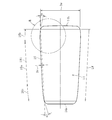
- FIG. 3 is an enlarged view of a portion B of FIG. 2
- FIG. 4 is an enlarged longitudinal sectional view of the inner ring of FIG. 1
- FIG. 4 is a schematic view showing the shape of the raceway surface of the inner ring in FIG. 4 in the generatrix direction, in which the radial dimension (vertical direction in the figure) is displayed at a magnification of about 500 to 1000 times the dimension in the generatrix direction.
- the characteristic configuration of the tapered roller bearing of the present embodiment is that a bearing functional surface that provides logarithmic crowning to the rolling surface of the tapered roller and sets the axial width of the straight portion at the center thereof, and the raceway of the raceway ring Paying attention to both the processing cost aspect of setting the crowning shape that does not raise the cost also, it was obtained by the idea of the combination of crowning that can maximize cost control and long life, logarithmic crowning is It is applied only to the tapered rollers, and at least the raceway surface of the inner ring and the outer ring is subjected to conventional cut crowning.
- the rolling surface 16 of the tapered roller 14 is composed of a straight portion 16a at the central portion in the generatrix direction and logarithmic crowning portions (hereinafter also simply referred to as crowning portions) 16b and 16c at both ends.
- the effective rolling surface width of the tapered roller 14 is LW
- the width of the straight portion 16a is LW1.
- the diameter on the large diameter side of the tapered roller 14 is the roller diameter Dw.
- a tangent angle ⁇ is formed at the ends of the crowning portions 16b and 16c.
- the logarithmic crowning applied to the tapered rollers 14 will be described.
- the buses of the crowning units 16b and 16c are obtained based on a logarithmic curve of logarithmic crowning represented by the following equation.
- the logarithmic crowning equation the one described in Japanese Patent No. 5037094 of the present applicant is cited.
- Design parameters K 1 , K 2, and z m in the above logarithmic crowning equation are designed.
- a mathematical optimization method for logarithmic crowning is described.
- An optimal logarithmic crowning design can be achieved by appropriately selecting K 1 and z m in a functional expression representing logarithmic crowning after defining the design parameter K 2 .
- Crowning is generally designed to reduce the maximum surface pressure or stress at the contact.
- K 1 and z m are selected so as to minimize the maximum value of the equivalent stress of Mises.
- K 1 and z m can be selected using an appropriate mathematical optimization method.
- Various algorithms for mathematical optimization methods have been proposed.
- One of the direct search methods is that optimization can be performed without using the derivative of the function. Useful when functions and variables cannot be directly represented by mathematical expressions.
- K 1 and z m are obtained by using Rosenblock method which is one of direct search methods.
- the shape of the crowning portions 16b and 16c of the tapered roller 14 in the present embodiment is a logarithmic curve crowning obtained by the above formula.
- the present invention is not limited to the above mathematical formula, and a logarithmic curve may be obtained using another logarithmic crowning formula.
- Crowning portions 16b and 16c of the tapered roller 14 shown in FIG. 2 are formed with a crowning shape that approximates the logarithmic curve of the logarithmic crowning calculated by the above formula. Details of the logarithmic crowning portion 16b formed on the large end face 14b side of the tapered roller 14 will be described with reference to FIG. 3 is exaggerated more than the tapered roller 14 shown in FIG. 2 so that the drop amount of the crowning 16b portion can be easily understood.
- the crowning portion 16b has a complex arc shape in which three arcs having large radii of curvature R1, R2, and R3 are smoothly connected to the straight portion 16a.
- the drop amount of the crowning portion 16b is approximated to a logarithmic curve by defining a first gate drop amount Dr1, an intermediate second gate drop amount Dr2, and a maximum third gate drop amount Dr3. It becomes the crowning shape.
- the drop amount Dr3 is Dr in the present specification and claims. Further, it corresponds to z m in the above-described Equation 1. Thereby, the edge surface pressure can be avoided and the surface pressure distribution in the axial direction can be made uniform.
- the drop amount differs depending on the size and model number, but is about 50 ⁇ m at the maximum. Since the crowning portion 16c formed on the small end surface 14a is the same as the crowning portion 16b, description thereof is omitted.
- the straight portion of the rolling surface of the tapered roller in the present specification and claims is used in the sense of including a linear shape and a substantially linear shape having a crowning with a drop amount of about several ⁇ m.
- the raceway surface 12a of the inner ring 12 is formed with a crowning center portion 12r1 formed of a center curve C1 having a large curvature radius R4 at the center portion in the generatrix direction, and the crowning center portion 12r1 has a width LG1.
- the radius of curvature R4 of the central curve C1 of the crowning center portion 12r1 is extremely large, which causes a drop amount of about 5 ⁇ m at both ends of the crowning center portion 12r1.
- Cut crowning portions 12r2 and 12r3 are formed on both sides of the crowning center portion 12r1 in the generatrix direction.
- the curvature radius R5 of the end curve C2 forming the cut crowning portion 12r2 and the curvature radius R6 of the end curve C3 forming the cut crowning portion 12r3 are both smaller than the curvature radius R4 of the central curve C1.
- the crowning central portion 12r1 and the cut crowning portions 12r2 and 12r3 are connected with smooth curves, respectively.
- the cut crowning portion 12r2 has a width LG2, the drop amount of the cut crowning portion 12r2 is Dc1, the cut crowning portion 12r3 has a width LG3, and the drop amount of the cut crowning portion 12r3 is Dc2.
- the drop amounts Dc1 and Dc2 are set to values necessary to prevent edge load from occurring under a high load or a high misalignment environment, for example, about 15 to 20 ⁇ m.
- the cut crown drop amount Dc in the claims is a generic term for the drop amounts Dc1 and Dc2.
- the cut crowning portions 12r2 and 12r3 formed on both sides of the crowning center portion 12r1 in the generatrix direction, the widths LG2 and LG3, the end curves C2 and C3, the curvature radii R5 and R6, and the drop amounts Dc1 and Dc2
- the present invention is not limited to this, and the cut crowning portions 12r2, 12r3, the widths LG2, LG3, the end curves C2, C3, the radius of curvature R5, R6 and the drop amounts Dc1, Dc2 are part or all of them. Sometimes they are the same.
- the effective raceway surface width of the raceway surface 12a is LG.
- the effective track surface width LG is also the sum of the width LG1 of the crowning center portion 12r1 and the width LG2 of the cut crowning portions 12r2 on both sides.
- the straight portion and the logarithmic crowning portion are formed on the rolling surface 16 of the tapered roller 14 described above, and the crowning central portion and the cut crowning portion are provided on the raceway surface 12 a of the inner ring 12.
- the drop amount Dr (Dr3) at the logarithmic crowning end, the tangent angle ⁇ , the workability, and the degree of change in the contact surface pressure value Table 1 shows the results of the verification.
- the ratio LW1 / LG of the roller straight portion width LW1 to the effective raceway surface width LG of the inner ring is 0.7 or more. It is desirable.
- the drop amount of the logarithmic crowning portion of the tapered roller is set in a range where super finishing can be performed, and the shortage of the drop amount is compensated by the conventional cut crowning of the inner ring or the outer ring. Therefore, even if the ratio LW1 / LG is 0.9 or more, it can be processed without problems. However, when the ratio LW1 / LG was 0.95, it was confirmed that the tangent angle ⁇ at the roller end portion was too large and the machining was difficult.
- the superfinishing of the tapered rollers is performed, for example, by supporting the tapered rollers on the guide screw surfaces formed on the pair of feed drums, and feeding them through the feed drums while rotating the tapered rollers.
- the roller outer peripheral surface is superfinished with a grindstone.
- the posture of the tapered roller is changed. For this reason, the screw bottom angle of the guide screw surface of the feed drum is changed.
- the contact angle ⁇ at the end of the tapered roller becomes too large, processing becomes difficult.
- Table 2 shows the verification results when the raceway surface of the inner ring is straight and logarithmic crowning is applied only to the tapered rollers.
- the clearance S between the small end surface 14a and the small collar surface 12d of the tapered roller 14 shown in FIG. 1 is set to 0.4 mm or less, it is possible to obtain an effect of suppressing the skew, and the familiar rotation when the tapered roller bearing 1 is assembled. As a result, the ease of assembly is improved.
- the clearance S is, for example, 0.4 mm or less in the size of a tapered roller bearing used in an automobile transmission, but in the case of a large size tapered roller bearing, the clearance S may be 0.5 mm or more. .
- the ratio (Dr + Dc) / Dw of the total drop amount Dr + Dc of the roller and inner ring crowning to the roller diameter Dw shown in FIGS. 2 and 4 is in the range of 0.003 ⁇ (Dr + Dc) /Dw ⁇ 0.03.
- the edge surface pressure can be set to an appropriate value, the workability is good, and the manufacturing cost can be reduced.
- (Dr + Dc) / Dw is smaller than 0.003, the edge surface pressure becomes larger, and when (Dr + Dc) / Dw is larger than 0.03, the drop amount Dr becomes too large, which makes manufacturing difficult.
- the drop amount of the logarithmic crowning portion of the tapered roller is set in a range where super finishing can be performed, and the shortage of the drop amount is caused by the inner ring or the outer ring.
- FIG. 6 is a longitudinal sectional view of an essential part of the automobile transmission
- FIG. 7 is a longitudinal sectional view of the automobile differential.
- a transmission 30 shown in FIG. 6 is an example of a synchronous mesh transmission.
- the input shaft 32 through a bearing 1 1 tapered rollers in the transmission case 31 is rotatably supported on the input shaft 32 coaxially, the spindle 33 is disposed.
- the input shaft 32 and the main shaft 33, the tapered roller bearing 1 2 pilot portions, and is rotatably supported. Although illustration is omitted, other portions of the main shaft 33 are also supported by tapered roller bearings.
- Input shaft 32 and the main shaft 33 and countershaft 34 disposed in parallel at predetermined intervals is supported by tapered roller bearing 1 3 and the other tapered roller bearings (not shown).
- An input shaft gear 35 is integrally provided on the input shaft 32, and always meshes with the countershaft gear 36 of the countershaft 34.
- Mainshaft gear to the main shaft 33 via a tapered roller bearing 1 4 idler portion being (hereinafter, simply referred to as gear) 43 is rotatably mounted.
- the main shaft gear 43 is always meshed with the gear 37 of the sub shaft 34.
- Tapered roller bearing according to the present embodiment refers to the other tapered roller bearing is omitted bearing 1 1 to 1 4 and illustrated tapered rollers above.
- the synchro mechanism 39 is moved in the axial direction (left-right direction in FIG. 6) by the operation of a selector (not shown) to perform a speed change operation.
- FIG. 5 is a longitudinal sectional view of a general automobile differential.
- a drive pinion shaft 101 is accommodated on the input side of the differential case 100 and is rotatably supported by a pair of tapered roller bearings 1 5 and 1 6 .
- a propeller shaft 102 is connected to one end of the drive pinion shaft 101, and a drive pinion gear (reduction small gear) 104 that meshes with a link gear (reduction large gear) 103 is integrally provided at the other end.
- the link gear 103 is connected to a differential gear case 105, and the differential gear case 105 is rotatably supported with respect to the differential case 100 by a pair of tapered roller bearings 1 7 and 18 .
- a pair of pinion gears 106 and a pair of side gears 107 that mesh with the pinion gears 106 are disposed inside the differential gear case 105.
- the pinion gear 106 is attached to the pinion shaft 108, and the side gear 107 is attached to the differential gear case 105.
- the left and right drive shafts (not shown) are connected to the inner diameter portion of the side gear 107 (such as serration connection).
- the tapered roller bearings of this embodiment are the tapered roller bearings 1 5 to 1 8 described above.
- the drive torque of the propeller shaft 102 is transmitted through a path of drive pinion gear 104 ⁇ link gear 103 ⁇ differential gear case 105 ⁇ pinion gear 106 ⁇ side gear 107 ⁇ drive shaft.
Landscapes
- Engineering & Computer Science (AREA)
- General Engineering & Computer Science (AREA)
- Mechanical Engineering (AREA)
- Rolling Contact Bearings (AREA)
Abstract
外周に円錐状の軌道面(12a)を有する内輪(12)と、内周に円錐状の軌道面(13a)を有する外輪(13)と、両軌道面(12a)、(13a)間に組込まれた複数の円すいころ(14)と、この円すいころ(14)を収容する保持器(15)とからなる円すいころ軸受(1)において、内輪(12)および外輪(13)のうち少なくとも内輪(12)の軌道面(12a)には、その母線方向の中央部に設けられた中央曲線(C1)と、この中央曲線(C1)の母線方向の両側に設けられ、中央曲線(C1)よりも曲率半径の小さい端部曲線(C2)とからなる複合曲線のカットクラウニングが形成され、円すいころ(14)の転動面(16)には、その母線方向の中央部に設けられたストレート部(16a)と、このストレート部(16a)の母線方向の両側に対数クラウニング部(16b)、(16c)が形成されており、内輪(12)の軌道面(12a)の有効軌道面幅をLGとし、円すいころ(14)の転動面(16)のストレート部(16a)の幅をLW1としたとき、0.7≦LW1/LG<0.95であることを特徴とする。
Description
本発明は、円すいころ軸受に関する。
自動車用途や産業機械用途に使用される円すいころ軸受は、大きな荷重やミスアライメントに対処するために、円すいころ軸受の軌道面(ころの転動面を含む)に発生する接触面圧を適正な大きさに抑える必要がある。円すいころ軸受の軌道面の接触面圧(エッジ面圧)を適正な範囲にするには、クラウニングの付与が必要である。具体的には、内輪、外輪およびころの各々にクラウニングを付与する手法や、ころにのみ大きなクラウニングあるいは対数クラウニングを付与する手法など、これまでに様々な手法が試みられている。
このような手法の中で、接触面圧を最も適正化し、軌道面内部に発生する応力の最小化により軸受寿命の延長が図れる手法として、特許文献1は、Johns-Goharの式に3つの設計パラメータを導入して整理した対数クラウニング式およびころ軸受を提案している。
また、面圧を適正化するクラウニング形状には、クラウニング形状を問わず転動体又は軌道輪の中心からのころの母線方向の2点のクラウニングドロップ量の範囲を規定した特許文献2がある。その他、特許文献3は、ころに対数クラウニングを付与すると共に、内輪、外輪のどちらか一方にも対数クラウニングを付与することを提案している。
クラウニングを付与する場合は、内外輪の加工コストを低減するために、内外輪のクラウニングは、転動体としてのころに集約し、ころの転動面にドロップ量の大きな単一アールのクラウニングあるいは対数クラウニングを付与することが好ましい。従い、内外輪にはドロップ量の小さな単一アールのクラウニング形状やクラウニング形状のないストレート形状の軌道面とすることが好ましいことが判明した。
ところが、荷重を受けた際の弾性変形状態において、単一アールのクラウニングは軸方向の中央部の接触長さが短くなってしまうことから、中央部の面圧が高くなり、早期に剥離が生じて軸受寿命が低下するという問題が判明した。
また、対数クラウニングの場合においても端部でのドロップ量が大きくなるため、研削加工上、クラウニング領域においてはある程度の軸方向幅が必要となることから、結果として、中央部の軸方向幅が短くなり、中央部の面圧が高くなって、わずかに軸受寿命が低下するという問題に至った。これに着目したのが本発明である。
本発明は、上記の問題に鑑み、接触面圧の抑制、長寿命化を低コストで実現する円すいころ軸受を提供することを目的とする。
本発明者は、上記の目的を達成するために種々検討した結果、円すいころの転動面に対数クラウニングを付与し、その母線方向中央部のストレート部の軸方向幅を設定するという軸受機能面と、軌道輪の軌道面もコスト上昇を生じないクラウニング形状を設定するという加工コスト面の両方に着目し、コスト抑制と長寿命化を最大限に発揮できるクラウニングの組合せについての着想により、本発明に至った。
前述の目的を達成するための技術的手段として、本発明は、外周に円錐状の軌道面を有する内輪と、内周に円錐状の軌道面を有する外輪と、前記両軌道面間に組込まれた複数の円すいころと、この円すいころを収容する保持器とからなる円すいころ軸受において、前記内輪および外輪のうち少なくとも前記内輪の軌道面には、その母線方向の中央部に設けられた中央曲線と、この中央曲線の母線方向の両側に設けられ、前記中央曲線よりも曲率半径の小さい端部曲線とからなる複合曲線のカットクラウニングが形成され、前記円すいころの転動面には、その母線方向の中央部に設けられたストレート部と、このストレート部の母線方向の両側に対数クラウニング部が形成されており、前記内輪の軌道面の有効軌道面幅をLGとし、前記円すいころの転動面の前記ストレート部の幅をLW1としたとき、0.7≦LW1/LG<0.95であることを特徴とする。
上記の構成により、円すいころ軸受の接触面圧を抑制し、長寿命化を低コストで実現することができる。
上記の対数クラウニング部のドロップ量をDr、円すいころの直径をDw、内輪の軌道面のカットクラウニングのドロップ量をDcとしたとき、0.003≦(Dr+Dc)/Dw≦0.03の範囲にあることが好ましい。これにより、エッジ面圧を適正な値にすることができ、かつ、加工性もよく、製造コストを低減することができる。
本発明の円すいころ軸受は、特に、トランスミッション用、デファレンシャル用として好適である。
本発明によれば、円すいころ軸受の接触面圧を抑制し、長寿命化を低コストで実現することができる。
本発明の一実施形態に係る円すいころ軸受を図1~図5に基づいて説明する。図1は、本実施形態の円すいころ軸受の中心線から上側半分を示す縦断面図である。
図1に示すように、円すいころ軸受1は、内輪12、外輪13、内輪12と外輪13との間に組込まれた円すいころ14、円すいころ14を保持する保持器15からなる。内輪12は外周に円錐状の軌道面12aが形成され、小径側に小つば部12bが設けられ、大径側に大つば部12cが設けられている。外輪13は内周に円錐状の軌道面13aが形成されている。内輪12の軌道面12aと外輪13の軌道面13aとの間に複数の円すいころ14が組み込まれている。各円すいころ14は、保持器15のポケット15aに収容され、円周方向等間隔に保持されている。
内輪12の軌道面12aと大つば部12cの大つば面12eとが交わる隅部に研削逃げ部12fが形成され、軌道面12aと小つば部12bの小つば面12dとが交わる隅部に研削逃げ部12gが形成されている。内輪12の軌道面12aには研削逃げ部12f、12gが設けられているので、軌道面12aの有効軌道面幅LG(図4参照)は円すいころ14の転動面16の有効転動面幅LW(図2参照)より小さい。
図1に示すように、円すいころ14の外周には、円錐状の転動面16が形成され、小径側に小端面14a、大径側に大端面14bが形成され、円すいころ14は、その大端面14bが内輪12の大つば面12eで受けられる。円すいころ14の転動面16は、図2に示すように、母線方向の中央部分のストレート部16aと両端部のクラウニング部16b、16cとからなる。図2に示すクラウニング部16b、16cのドロップ量は誇張して表示している。クラウニング部16b、16cの詳細は後述する。図1に示すように、保持器15は、小径側環状部15bと、大径側環状部15cと、小径側環状部15bと大径側環状部15cとを軸方向に繋ぐ複数の柱部15dとからなる。
本実施形態の円すいころ軸受の概要は以上のとおりである。次に、本実施形態の円すいころ軸受の特徴的な構成を図2~図5に基づいて説明する。図2は、図1の円すいころを拡大した正面図で、図3は、図2のB部を拡大した図で、図4は、図1の内輪を拡大した縦断面図で、図5は、図4の内輪の軌道面の母線方向の形状を示す模式図で、母線方向寸法に対して半径方向寸法(図の上下方向)を500~1000倍程度の倍率で表示したものである。
本実施形態の円すいころ軸受の特徴的な構成は、円すいころの転動面に対数クラウニングを付与し、その中央部のストレート部の軸方向幅を設定するという軸受機能面と、軌道輪の軌道面もコスト上昇を生じないクラウニング形状を設定するという加工コスト面の両方に着目し、コスト抑制と長寿命化を最大限に発揮できるクラウニングの組合せについての着想により得られたもので、対数クラウニングは円すいころにのみ施され、内輪および外輪のうち少なくとも内輪の軌道面には、従来のカットクラウニングが施されたものである。
図2に示すように、円すいころ14の転動面16は、母線方向の中央部分のストレート部16aと両端部の対数クラウニング部(以下、単にクラウニング部ともいう)16b、16cとからなる。円すいころ14の有効転動面幅はLWで、ストレート部16aの幅はLW1である。円すいころ14の大径側の直径がころ径Dwである。クラウニング部16b、16cの端部には接線角度αが形成されている。
ここで、円すいころ14に施された対数クラウニングに関して説明する。クラウニング部16b、16cの母線は、一例として、次式で表される対数クラウニングの対数曲線に基づいて求められる。この対数クラウニング式は、本出願人の特許第5037094号公報に記載されたものを引用した。

上記の対数クラウニング式中の設計パラメータK1、K2およびzmが設計の対象となる。対数クラウニングの数理的最適化手法について説明する。設計パラメータK2を定めた上で、対数クラウニングを表す関数式中のK1、zmを適切に選択することによって、最適な対数クラウニング設計することができる。クラウニングは一般的に接触部の面圧もしくは応力の最大値を低下させるように設計する。ここでは、転動疲労寿命は、Misesの降伏条件に従って発生すると考え、Misesの相当応力の最大値を最小にするようにK1、zmを選択する。K1、zmは適当な数理的最適化手法を用いて選択することが可能である。数理的最適化手法のアルゴリズムには種々のものが提案されているが、その一つである直接探索法は、関数の微係数を使用せずに最適化を実行することが可能であり、目的関数と変数が数式によって直接的に表現できない場合に有用である。ここでは、直接探索法の一つであるRosenbrock法を用いてK1、zmを求める。
本実施形態における円すいころ14のクラウニング部16b、16cの形状は、上記の数式によって求められた対数曲線クラウニングとした。ただし、上記の数式に限られるものではなく、他の対数クラウニング式を用いて対数曲線を求めてもよい。
図2に示す円すいころ14のクラウニング部16b、16cには上記の数式で求められた対数クラウニングの対数曲線に近似する形状のクラウニングが形成されている。円すいころ14の大端面14b側に形成された対数クラウニング部16bの詳細を図3に基づいて説明する。図3はクラウニング16b部のドロップ量を理解しやすいように図2に示す円すいころ14よりも更に誇張して表示している。クラウニング部16bは、ストレート部16aに大きな曲率半径R1、R2、R3をもつ3つの円弧が滑らかに接続され複合的な円弧形状で構成されている。そして、クラウニング部16bのドロップ量として、第1のゲートのドロップ量Dr1、中間の第2のゲートのドロップ量Dr2、最大の第3のゲートのドロップ量Dr3を規定することにより、対数曲線に近似したクラウニング形状となる。ドロップ量Dr3が、本明細書および請求の範囲におけるDrである。また、前述した数式1中のzmに相当する。これにより、エッジ面圧を回避し軸方向の面圧分布を均一化できる。ドロップ量は、サイズや型番によって異なるが、最大でも50μm程度である。小端面14aに形成されたクラウニング部16cは、クラウニング部16bと同様であるので、説明を省略する。本明細書および請求の範囲における円すいころの転動面のストレート部は、直線状の他、ドロップ量が数μm程度のクラウニングのある概略直線状のものを含む意味で用いる。
次に、内輪12および外輪13のうち少なくとも内輪12の軌道面12aに施されたカットクラウニングについて図4および図5に基づいて説明する。内輪12の軌道面12aは、その母線方向の中央部に曲率半径R4の大きい中央曲線C1からなるクラウニング中央部12r1が形成され、このクラウニング中央部12r1は幅LG1を有する。クラウニング中央部12r1の中央曲線C1の曲率半径R4は、クラウニング中央部12r1の両端で5μm程度のドロップ量が生じる極めて大きなものである。
クラウニング中央部12r1の母線方向の両側にカットクラウニング部12r2、12r3が形成されている。カットクラウニング部12r2を形成する端部曲線C2の曲率半径R5およびカットクラウニング部12r3を形成する端部曲線C3の曲率半径R6は、いずれも中央曲線C1の曲率半径R4より小さい。クラウニング中央部12r1とカットクラウニング部12r2、12r3との間は、それぞれ滑らかな曲線で接続されている。カットクラウニング部12r2は幅LG2を有し、カットクラウニング部12r2のドロップ量はDc1であり、カットクラウニング部12r3は幅LG3を有し、カットクラウニング部12r3のドロップ量はDc2である。このドロップ量Dc1、Dc2は、例えば、高荷重下、あるいは、高いミスアライメント環境下でのエッジロードの発生を防止するに必要な値に設定され、15~20μm程度である。請求の範囲におけるカットクラウニングのドロップ量Dcは、上記のドロップ量Dc1とDc2を総称したものである。
本実施形態では、クラウニング中央部12r1の母線方向の両側に形成されるカットクラウニング部12r2、12r3、その幅LG2、LG3、端部曲線C2、C3、曲率半径R5、R6およびドロップ量Dc1、Dc2が互いに異なるものを例示したが、これに限られず、カットクラウニング部12r2、12r3、その幅LG2、LG3、端部曲線C2、C3、曲率半径R5、R6およびドロップ量Dc1、Dc2の一部あるいは全部が互いに同じ場合もある。
図4に示すように、内輪12の軌道面12aには研削逃げ部12f、12gが設けられているので、軌道面12aの有効軌道面幅はLGとなる。有効軌道面幅LGは、クラウニング中央部12r1の幅LG1と両側のカットクラウニング部12r2の幅LG2とを加算したものでもある。
以上では、内輪12の軌道面12aのクラウニング中央部12r1および両側のカットクラウニング部12r2を説明したが、外輪13の軌道面13aにカットクラウニングを施す場合には、内輪12のクラウニングと同様であるので、説明は省略する。
次に、前述した円すいころ14の転動面16にストレート部と対数クラウニング部を形成すると共に、内輪12の軌道面12aに、クラウニング中央部とカットクラウニング部を施した場合について、円すいころ14のストレート部の幅LW1と内輪12の有効軌道面幅LGの比を異ならせて、対数クラウニング端部でのドロップ量Dr(Dr3)と、その接線角度α、加工性および接触面圧値の変化度合についての検証結果を表1に示す。

表1に示す検証においては、円すいころのストレート部の幅LW1と輪の有効軌道面幅LGとの比較とし、比LW1/LGを異ならせて評価した。この理由は、内輪の軌道面にカットクラウニングが施されているので、内輪の有効軌道面幅LGとの比の方がより即応した検証結果が得られるとの考えによる。内輪の有効軌道面幅LGと後述する段落0038の表2に示す円すいころの有効転動面幅LWとの比LW/LGは1.1~1.2程度である。比LW/LGが1.1~1.2程度であるため、表1のLW1/LG=0.6は表2のLW1/LW=0.5とほぼ同義であり、LW1/LG=0.6の場合はクラウニングを円すいころに集約するのが加工上望ましいことから、カットクラウニングは不要とした。
表1に示すように、中央部の接触面圧を効果的に下げるためには、内輪の有効軌道面幅LGに対するころのストレート部の幅LW1の比LW1/LGは、0.7以上とすることが望ましい。本実施形態の円すいころ軸受1では、円すいころの対数クラウニング部のドロップ量を超仕上げ加工が可能な範囲に設定した上で、ドロップ量の不足分は、内輪ないしは外輪の従来のカットクラウニングで補うことにより、比LW1/LGが0.9以上でも問題なく加工できる。ただし、比LW1/LGが0.95になると、ころ端部での接線角度αが大きくなり過ぎて加工が困難であることが確認できた。
ここで、円すいころ端部の接触角度αが大きくなり過ぎると超仕上げ加工が困難になる理由を説明する。図示は省略するが、円すいころの超仕上げ加工は、例えば、一対のフィードドラムに形成された案内ねじ面に円すいころを支持し、円すいころを回転させながらフィードドラム間を通し送りされ、その際、ころ外周面が砥石により超仕上げ加工される。円すいころのストレート部と対数クラウニング部を超仕上げ加工するために円すいころの姿勢を変化させる。このためにフィードドラムの案内ねじ面のねじ底角度を変化させているが、円すいころ端部の接触角度αが大きくなり過ぎると加工が困難になる。
以上の検証結果より、比LW1/LGを0.7≦LW1/LG<0.95の範囲とすることにより、接触面圧の低減およびエッジロードの発生を抑えることができ、かつ、加工性もよく、製造コストを低減することができる。
これに対して、開発過程の知見として、内輪の軌道面はストレート形状で、円すいころのみに対数クラウニングを施した場合の検証結果を表2に示す。

表2に示すように、円すいころにのみ対数クラウニングを施した場合は、ころの有効転動面幅LWに対するストレート部の幅LW1の比LW1/LWが0.9以上になると、ころ端部での接線角度αが大きくなり過ぎて、加工が困難である。また、比LW1/LWが0.45では、中央部の接触面圧が増加することから実用不可となった。
図1に示す円すいころ14の小端面14aと小つば面12dとのすきまSを0.4mm以下に設定したので、スキューの抑制効果が得られると共に、円すいころ軸受1の組込時の馴染み回転を減らし組付け性も良好となる。上記のすきまSは、例えば、自動車用トランスミッションに使用される円すいころ軸受のサイズでは0.4mm以下であるが、大きなサイズの円すいころ軸受の場合は、すきまSは0.5mm以上のものもある。
図2および図4に示すころ径Dwに対するころと内輪のクラウニングの合計ドロップ量Dr+Dcの比(Dr+Dc)/Dwは、0.003≦(Dr+Dc)/Dw≦0.03の範囲とすることにより、エッジ面圧を適正な値にすることができ、かつ、加工性もよく、製造コストを低減することができる。(Dr+Dc)/Dwが0.003より小さいとエッジ面圧が大きくなり、(Dr+Dc)/Dwが0.03より大きいとドロップ量Drが大きくなり過ぎて製造困難となる。
以上説明したように、本実施形態の円すいころ軸受1は、円すいころの対数クラウニング部のドロップ量を超仕上げ加工が可能な範囲に設定した上で、ドロップ量の不足分は、内輪ないしは外輪の従来のカットクラウニングで補うことにより、ストレート部を長く確保し、接触面圧の低減およびエッジロードの発生を抑えることができ、かつ、加工性もよく、製造コストを低減することができるという顕著な効果を有する。
最後に、本実施形態の円すいころ軸受1の好適な用途として、自動車用トランスミッションおよび自動車用デファレンシャルの概要を図6および図7に基づいて説明する。図6は自動車用トランスミッションの要部の縦断面図で、図7は自動車用デファレンシャルの縦断面図である。
図6に示すトランスミッション30は同期噛合式変速機の一例である。ミッションケース31に円すいころ軸受11を介して入力軸32が回転自在に支持され、入力軸32と同軸上に、主軸33が配置されている。入力軸32と主軸33は、パイロット部の円すいころ軸受12により、相対回転可能に支持されている。図示は省略するが、主軸33の他の部位も円すいころ軸受によって支持されている。入力軸32および主軸33と所定間隔で平行配置された副軸34は、円すいころ軸受13と他の円すいころ軸受(図示省略)によって支持されている。入力軸32には入力軸歯車35が一体に設けられ、副軸34の副軸歯車36に常時噛合っている。
主軸33にはアイドラ部の円すいころ軸受14を介して主軸歯車(以下、単に歯車ともいう)43が回転自在に装着されている。主軸歯車43は、副軸34の歯車37に常時噛合っている。本実施形態に係る円すいころ軸受は、上記の円すいころ軸受11~14および図示を省略した他の円すいころ軸受を指す。シンクロ機構39は、セレクタ(図示省略)の作動によって軸方向(図6の左右方向)移動し変速操作が行われる。
次に、デファレンシャルを図7に基づいて説明する。図5は一般的な自動車のデファレンシャルの縦断面図である。デファレンシャルケース100の入力側にドライブピニオン軸101が収容され、一対の円すいころ軸受15、16により回転自在に支持される。ドライブピニオン軸101の一端部にはプロペラシャフト102が連結され、他端部にはリンクギヤ(減速大歯車)103とかみ合うドライブピニオンギヤ(減速小歯車)104が一体に設けられている。
リンクギヤ103は差動歯車ケース105に連結され、差動歯車ケース105は一対の円すいころ軸受17、18によりデファレンシャルケース100に対して回転自在に支持される。差動歯車ケース105の内部に、一対のピニオンギヤ106と、これとかみ合う一対のサイドギヤ107とがそれぞれ配設される。ピニオンギヤ106はピニオン軸108に装着され、サイドギヤ107は差動歯車ケース105に装着されている。サイドギヤ107の内径部に左右のドライブシャフト(図示省略)が連結(セレーション連結等)される。本実施形態の円すいころ軸受は、上記の円すいころ軸受15~18である。プロペラシャフト102の駆動トルクは、ドライブピニオンギヤ104→リンクギヤ103→差動歯車ケース105→ピニオンギヤ106→サイドギヤ107→ドライブシャフトという経路で伝達される。
本発明は前述した実施形態に何ら限定されるものではなく、本発明の要旨を逸脱しない範囲内において、さらに種々の形態で実施し得ることは勿論のことであり、本発明の範囲は、請求の範囲によって示され、さらに請求の範囲に記載の均等の意味、および範囲内のすべての変更を含む。
1 円すいころ軸受
12 内輪
12a 軌道面
12b 小つば部
12c 大つば部
12d 小つば面
12e 大つば面
12f 研削逃げ部
12g 研削逃げ部
12r1 クラウニング中央部
12r2 カットクラウニング部
13 外輪
13a 軌道面
14 円すいころ
14a 小端面
14b 大端面
15 保持器
16 転動面
16a ストレート部
16b 対数クラウニング部
16c 対数クラウニング部
C1 中央曲線
C2 端部曲線
Dc カットクラウニング部ドロップ量
Dr 対数クラウニング端部ドロップ量
Dw ころ径
LG 有効軌道面幅
LG1 クラウニング中央部幅
LG2 カットクラウニング部幅
LW 有効転動面幅
LW1 ストレート部幅
S すきま
12 内輪
12a 軌道面
12b 小つば部
12c 大つば部
12d 小つば面
12e 大つば面
12f 研削逃げ部
12g 研削逃げ部
12r1 クラウニング中央部
12r2 カットクラウニング部
13 外輪
13a 軌道面
14 円すいころ
14a 小端面
14b 大端面
15 保持器
16 転動面
16a ストレート部
16b 対数クラウニング部
16c 対数クラウニング部
C1 中央曲線
C2 端部曲線
Dc カットクラウニング部ドロップ量
Dr 対数クラウニング端部ドロップ量
Dw ころ径
LG 有効軌道面幅
LG1 クラウニング中央部幅
LG2 カットクラウニング部幅
LW 有効転動面幅
LW1 ストレート部幅
S すきま
Claims (3)
- 外周に円錐状の軌道面を有する内輪と、内周に円錐状の軌道面を有する外輪と、前記両軌道面間に組込まれた複数の円すいころと、この円すいころを収容する保持器とからなる円すいころ軸受において、
前記内輪および外輪のうち少なくとも前記内輪の軌道面には、その母線方向の中央部に設けられた中央曲線と、この中央曲線の母線方向の両側に設けられ、前記中央曲線よりも曲率半径の小さい端部曲線とからなる複合曲線のカットクラウニングが形成され、
前記円すいころの転動面には、その母線方向の中央部に設けられたストレート部と、このストレート部の母線方向の両側に対数クラウニング部が形成されており、
前記内輪の軌道面の有効軌道面幅をLGとし、前記円すいころの転動面の前記ストレート部の幅をLW1としたとき、0.7≦LW1/LG<0.95であることを特徴とする円すいころ軸受。 - 前記対数クラウニング部のドロップ量をDr、前記円すいころの直径をDw、前記内輪の軌道面のカットクラウニングのドロップ量をDcとしたとき、0.003≦(Dr+Dc)/Dw≦0.03の範囲にあることを特徴とする請求項1に記載の円すいころ軸受。
- 前記円すいころ軸受の用途がトランスミッション又はデファレンシャルであることを特徴とする請求項1又は請求項2に記載の円すいころ軸受。
Priority Applications (3)
| Application Number | Priority Date | Filing Date | Title |
|---|---|---|---|
| CN201780054455.3A CN109661522B (zh) | 2016-09-06 | 2017-08-25 | 圆锥滚子轴承 |
| US16/329,261 US10731703B2 (en) | 2016-09-06 | 2017-08-25 | Tapered roller bearing |
| EP17848582.7A EP3511586B1 (en) | 2016-09-06 | 2017-08-25 | Tapered roller bearing |
Applications Claiming Priority (2)
| Application Number | Priority Date | Filing Date | Title |
|---|---|---|---|
| JP2016-173630 | 2016-09-06 | ||
| JP2016173630A JP6838899B2 (ja) | 2016-09-06 | 2016-09-06 | 円すいころ軸受 |
Publications (1)
| Publication Number | Publication Date |
|---|---|
| WO2018047641A1 true WO2018047641A1 (ja) | 2018-03-15 |
Family
ID=61562587
Family Applications (1)
| Application Number | Title | Priority Date | Filing Date |
|---|---|---|---|
| PCT/JP2017/030619 Ceased WO2018047641A1 (ja) | 2016-09-06 | 2017-08-25 | 円すいころ軸受 |
Country Status (5)
| Country | Link |
|---|---|
| US (1) | US10731703B2 (ja) |
| EP (1) | EP3511586B1 (ja) |
| JP (1) | JP6838899B2 (ja) |
| CN (1) | CN109661522B (ja) |
| WO (1) | WO2018047641A1 (ja) |
Cited By (1)
| Publication number | Priority date | Publication date | Assignee | Title |
|---|---|---|---|---|
| WO2021153793A1 (ja) * | 2020-01-30 | 2021-08-05 | 日本精工株式会社 | ころ軸受 |
Families Citing this family (4)
| Publication number | Priority date | Publication date | Assignee | Title |
|---|---|---|---|---|
| CN111188832A (zh) * | 2020-03-12 | 2020-05-22 | 洛阳Lyc轴承有限公司 | 一种能效型圆锥滚子轴承 |
| CN111946736B (zh) * | 2020-08-14 | 2022-05-27 | 中车大连机车研究所有限公司 | 一种圆锥滚子轴承 |
| DE102020130456A1 (de) * | 2020-11-18 | 2022-05-19 | Aktiebolaget Skf | Kegelrollenlager |
| CN113530981B (zh) * | 2021-08-06 | 2023-09-12 | 中车大连机车研究所有限公司 | 一种城市轨道交通轴箱用双列圆锥滚子轴承 |
Citations (6)
| Publication number | Priority date | Publication date | Assignee | Title |
|---|---|---|---|---|
| JPS5037094B1 (ja) | 1971-02-17 | 1975-11-29 | ||
| JP2001065574A (ja) * | 1999-08-31 | 2001-03-16 | Nsk Ltd | ころ軸受 |
| JP2005155763A (ja) * | 2003-11-25 | 2005-06-16 | Ntn Corp | ころ軸受 |
| JP2007051715A (ja) * | 2005-08-18 | 2007-03-01 | Jtekt Corp | 円錐ころ軸受、円錐ころ軸受装置及びこれを用いた車両用ピニオン軸支持装置 |
| JP2010106974A (ja) | 2008-10-30 | 2010-05-13 | Nsk Ltd | 円すいころ軸受 |
| JP2014052069A (ja) * | 2012-08-06 | 2014-03-20 | Nsk Ltd | 円筒ころ軸受 |
Family Cites Families (16)
| Publication number | Priority date | Publication date | Assignee | Title |
|---|---|---|---|---|
| FR2615575B1 (fr) * | 1987-05-22 | 1994-01-14 | Glaenzer Spicer | Roulement a rouleaux coniques entrecroises, et application a un moyeu pour automobile |
| US5752775A (en) * | 1994-08-31 | 1998-05-19 | Ntn Corporation | Roller bearing |
| US6328477B1 (en) * | 1998-11-27 | 2001-12-11 | Ntn Corporation | Tapered roller bearings and gear shaft support devices |
| JP3757308B2 (ja) * | 1999-03-10 | 2006-03-22 | 株式会社ジェイテクト | 円錐ころ軸受およびその製造方法 |
| US6547443B2 (en) * | 2000-10-17 | 2003-04-15 | Ntn Corporation | Tapered roller bearing |
| US6502996B2 (en) * | 2001-05-11 | 2003-01-07 | The Timken Company | Bearing with low wear and low power loss characteristics |
| CN100422586C (zh) * | 2004-02-19 | 2008-10-01 | 株式会社捷太格特 | 圆锥滚子轴承 |
| JP2007051714A (ja) * | 2005-08-18 | 2007-03-01 | Jtekt Corp | 円錐ころ軸受、及びこれを用いた車両用ピニオン軸支持装置 |
| JP2007051716A (ja) * | 2005-08-18 | 2007-03-01 | Jtekt Corp | 円錐ころ軸受、及びこれを用いた車両用ピニオン軸支持装置 |
| JP2007170418A (ja) * | 2005-12-19 | 2007-07-05 | Ntn Corp | 円すいころ軸受 |
| JP2008014473A (ja) * | 2006-07-10 | 2008-01-24 | Ntn Corp | 車輪用軸受装置 |
| DE102006052043A1 (de) * | 2006-11-04 | 2008-05-08 | Ab Skf | Laufbahnelement und Kegelrollenlagerung mit dem Laufbahnelement |
| JP5037094B2 (ja) | 2006-11-15 | 2012-09-26 | Ntn株式会社 | ころ軸受 |
| CN101158371A (zh) * | 2007-11-07 | 2008-04-09 | 张荣发 | 实现圆锥滚子轴承低摩擦的方法及其结构 |
| JP5334665B2 (ja) * | 2009-04-24 | 2013-11-06 | Ntn株式会社 | 円すいころ軸受およびその設計方法 |
| CN202209352U (zh) * | 2011-08-05 | 2012-05-02 | 福建省永安轴承有限责任公司 | 结构优化的长寿命圆锥滚子轴承 |
-
2016
- 2016-09-06 JP JP2016173630A patent/JP6838899B2/ja not_active Expired - Fee Related
-
2017
- 2017-08-25 CN CN201780054455.3A patent/CN109661522B/zh not_active Expired - Fee Related
- 2017-08-25 WO PCT/JP2017/030619 patent/WO2018047641A1/ja not_active Ceased
- 2017-08-25 US US16/329,261 patent/US10731703B2/en not_active Expired - Fee Related
- 2017-08-25 EP EP17848582.7A patent/EP3511586B1/en not_active Not-in-force
Patent Citations (7)
| Publication number | Priority date | Publication date | Assignee | Title |
|---|---|---|---|---|
| JPS5037094B1 (ja) | 1971-02-17 | 1975-11-29 | ||
| JP2001065574A (ja) * | 1999-08-31 | 2001-03-16 | Nsk Ltd | ころ軸受 |
| JP3731401B2 (ja) | 1999-08-31 | 2006-01-05 | 日本精工株式会社 | ころ軸受 |
| JP2005155763A (ja) * | 2003-11-25 | 2005-06-16 | Ntn Corp | ころ軸受 |
| JP2007051715A (ja) * | 2005-08-18 | 2007-03-01 | Jtekt Corp | 円錐ころ軸受、円錐ころ軸受装置及びこれを用いた車両用ピニオン軸支持装置 |
| JP2010106974A (ja) | 2008-10-30 | 2010-05-13 | Nsk Ltd | 円すいころ軸受 |
| JP2014052069A (ja) * | 2012-08-06 | 2014-03-20 | Nsk Ltd | 円筒ころ軸受 |
Non-Patent Citations (1)
| Title |
|---|
| See also references of EP3511586A4 |
Cited By (3)
| Publication number | Priority date | Publication date | Assignee | Title |
|---|---|---|---|---|
| WO2021153793A1 (ja) * | 2020-01-30 | 2021-08-05 | 日本精工株式会社 | ころ軸受 |
| JP7468550B2 (ja) | 2020-01-30 | 2024-04-16 | 日本精工株式会社 | ころ軸受 |
| US12110925B2 (en) | 2020-01-30 | 2024-10-08 | Nsk Ltd. | Roller bearing |
Also Published As
| Publication number | Publication date |
|---|---|
| US20190219098A1 (en) | 2019-07-18 |
| CN109661522A (zh) | 2019-04-19 |
| US10731703B2 (en) | 2020-08-04 |
| EP3511586A1 (en) | 2019-07-17 |
| EP3511586A4 (en) | 2020-06-24 |
| CN109661522B (zh) | 2021-08-13 |
| JP2018040400A (ja) | 2018-03-15 |
| EP3511586B1 (en) | 2022-01-12 |
| JP6838899B2 (ja) | 2021-03-03 |
Similar Documents
| Publication | Publication Date | Title |
|---|---|---|
| WO2018047641A1 (ja) | 円すいころ軸受 | |
| WO2010122955A1 (ja) | 円すいころ軸受およびその設計方法 | |
| JP2018136027A (ja) | 円すいころ軸受 | |
| WO2011062257A1 (ja) | タンデムアンギュラ型玉軸受 | |
| WO2018020951A1 (ja) | 自動車用円すいころ軸受 | |
| JP6739968B2 (ja) | 円すいころ軸受 | |
| JP7089369B2 (ja) | 保持器付きころおよび遊星歯車支持構造 | |
| US11261942B2 (en) | Speed reducer capable of changing speed | |
| JP6108321B2 (ja) | ベルト式無段変速機 | |
| JP7394939B2 (ja) | 円すいころ軸受 | |
| JP2008106869A (ja) | 玉軸受 | |
| JP2019168084A (ja) | 円筒ころ軸受用保持器および円筒ころ軸受 | |
| EP1485638B1 (en) | Gear unit | |
| JP2018204730A (ja) | はすば歯車装置 | |
| JP7706382B2 (ja) | 遊星歯車装置 | |
| EP3940252B1 (en) | Rolling bearing | |
| JP6351645B2 (ja) | 回転軸構造 | |
| JP6897559B2 (ja) | 車両用動力伝達装置 | |
| JP2007139019A (ja) | 円すいころ軸受 | |
| CN104797852A (zh) | 变速器 | |
| JP2016070346A (ja) | 円筒ころ軸受 | |
| JPH11173335A (ja) | 複列転がり軸受装置 |
Legal Events
| Date | Code | Title | Description |
|---|---|---|---|
| 121 | Ep: the epo has been informed by wipo that ep was designated in this application |
Ref document number: 17848582 Country of ref document: EP Kind code of ref document: A1 |
|
| NENP | Non-entry into the national phase |
Ref country code: DE |
|
| ENP | Entry into the national phase |
Ref document number: 2017848582 Country of ref document: EP Effective date: 20190408 |