WO2018047835A1 - 歯列矯正用インプラント装置 - Google Patents
歯列矯正用インプラント装置 Download PDFInfo
- Publication number
- WO2018047835A1 WO2018047835A1 PCT/JP2017/032006 JP2017032006W WO2018047835A1 WO 2018047835 A1 WO2018047835 A1 WO 2018047835A1 JP 2017032006 W JP2017032006 W JP 2017032006W WO 2018047835 A1 WO2018047835 A1 WO 2018047835A1
- Authority
- WO
- WIPO (PCT)
- Prior art keywords
- pair
- fixing
- bridge member
- extension arm
- wire
- Prior art date
- Legal status (The legal status is an assumption and is not a legal conclusion. Google has not performed a legal analysis and makes no representation as to the accuracy of the status listed.)
- Ceased
Links
Images


Classifications
-
- A—HUMAN NECESSITIES
- A61—MEDICAL OR VETERINARY SCIENCE; HYGIENE
- A61C—DENTISTRY; APPARATUS OR METHODS FOR ORAL OR DENTAL HYGIENE
- A61C8/00—Means to be fixed to the jaw-bone for consolidating natural teeth or for fixing dental prostheses thereon; Dental implants; Implanting tools
- A61C8/0093—Features of implants not otherwise provided for
- A61C8/0096—Implants for use in orthodontic treatment
-
- A—HUMAN NECESSITIES
- A61—MEDICAL OR VETERINARY SCIENCE; HYGIENE
- A61C—DENTISTRY; APPARATUS OR METHODS FOR ORAL OR DENTAL HYGIENE
- A61C7/00—Orthodontics, i.e. obtaining or maintaining the desired position of teeth, e.g. by straightening, evening, regulating, separating, or by correcting malocclusions
-
- A—HUMAN NECESSITIES
- A61—MEDICAL OR VETERINARY SCIENCE; HYGIENE
- A61C—DENTISTRY; APPARATUS OR METHODS FOR ORAL OR DENTAL HYGIENE
- A61C7/00—Orthodontics, i.e. obtaining or maintaining the desired position of teeth, e.g. by straightening, evening, regulating, separating, or by correcting malocclusions
- A61C7/10—Devices having means to apply outwardly directed force, e.g. expanders
-
- A—HUMAN NECESSITIES
- A61—MEDICAL OR VETERINARY SCIENCE; HYGIENE
- A61C—DENTISTRY; APPARATUS OR METHODS FOR ORAL OR DENTAL HYGIENE
- A61C7/00—Orthodontics, i.e. obtaining or maintaining the desired position of teeth, e.g. by straightening, evening, regulating, separating, or by correcting malocclusions
- A61C7/12—Brackets; Arch wires; Combinations thereof; Accessories therefor
-
- A—HUMAN NECESSITIES
- A61—MEDICAL OR VETERINARY SCIENCE; HYGIENE
- A61C—DENTISTRY; APPARATUS OR METHODS FOR ORAL OR DENTAL HYGIENE
- A61C7/00—Orthodontics, i.e. obtaining or maintaining the desired position of teeth, e.g. by straightening, evening, regulating, separating, or by correcting malocclusions
- A61C7/12—Brackets; Arch wires; Combinations thereof; Accessories therefor
- A61C7/20—Arch wires
Definitions
- the present invention relates to an orthodontic implant device for moving teeth while being fixed in the oral cavity.
- the implantation position is often limited due to the proximity of the root of adjacent teeth, the extension of the maxillary sinus between the roots, and the narrow width of the attached gingiva. Even if it can be embedded in the alveolar bone between narrow roots, its presence may limit the movement of the teeth. Furthermore, if the bone quality is poor, the dropout rate increases, and there are many problems such as damage to the root during implantation, the dropout of the implant anchor, and the implantation of the implant anchor head in the gingiva that occurs during implantation into the free gingival region.
- the applicant of the present application includes a pair of anchor members fixed in the oral cavity, a bridge member formed to extend between the pair of anchor members, and fixed to the pair of anchor members, and the bridge.
- An orthodontic appliance provided with a prismatic receiving portion that is disposed on the member and into which a square wire can be inserted, and a connecting member into which a part of the extension arm is inserted and connected to the prismatic receiving portion.
- An implant device was developed (see Patent Document 1). According to this orthodontic implant device, the extension arm can be stably fixed in the oral cavity without rotating by inserting the insertion portion made of the square wire of the extension arm into the prismatic receiving portion. .
- an insertion part made of a square wire was joined to an arm part made of a wire that moves the tooth while being fixed to the tooth, such as brazing. Even if the arm portion is made of an alloy, there is a problem that elasticity is lost due to heating during brazing. Moreover, since the insertion part joined to an arm part is very small, especially when a dentist creates an arm part according to the treatment content etc., there was also a problem that brazing was troublesome and time-consuming.
- the present invention has been made on the basis of such problems, and provides an orthodontic implant device that can be easily produced and can expand the range of material selection that constitutes an extension arm. With the goal.
- An orthodontic implant device is an orthodontic implant that is fixed in the oral cavity and connected to an extension arm made of a wire for moving the teeth.
- a pair of anchor members having a shaft formed with a head groove formed on one end of the shaft, and a head groove having a side surface and a bottom surface perpendicular to each other.
- a bridge member disposed so as to connect the pair of anchor members, a fixing portion for fixing the extension arm, and a wire-like protrusion for arranging the fixing portion on the bridge member.
- the bridge member is provided with a connection portion provided with an insertion hole for inserting the protrusion, and a pair of square wires that are provided in the connection portion and are fitted in the head grooves of the pair of anchor members.
- Another orthodontic implant device comprises a wire, an extension arm that is fixed to a tooth and moves the tooth, a shaft that is fixed in the oral cavity and has a thread formed thereon, A pair of anchor members each having a head portion formed at one end portion, and having a head groove having a vertical relationship between a side surface and a bottom surface, and the pair of anchor members.
- a bridge member a mounting member having a fixing part for fixing the extension arm, and a wire-shaped protrusion for mounting the fixing part on the bridge member, Has a connecting portion provided with an insertion hole for inserting the protrusion, and a pair of square wire-like portions disposed in the connecting portion and fitted to the head grooves of the pair of anchor members, and the fixing portion is The vertical relationship between the side and bottom It has a fixing groove that is intended to fix by caulking fitted part of the extension arm.
- the orthodontic implant device includes a disposing member having a fixing portion for fixing the extension arm and a wire-like protrusion for disposing the fixing portion on the bridge member,
- the fixing part is formed with a fixing groove whose side and bottom are perpendicular to each other and fixed by fitting and crimping part of the extension arm. Therefore, the range of material selection can be expanded. Moreover, even if the size of the member is small, it can be easily fixed, and labor can be reduced.
- the arrangement member can be prevented from rotating and wobbling, and can be stably arranged. can do.
- the protrusions of the arrangement member are inserted into the insertion holes of the bridge member, and, for example, the arrangement members are connected by ligation wires through the ligation wires between the respective fixation portions.
- the bridge member can be easily fixed. Therefore, it is not necessary to provide a special hook for hooking the ligature wire, and the configuration can be simplified.
- FIG. 1 It is a figure showing the structure of the orthodontic implant apparatus which concerns on one embodiment of this invention. It is a figure showing the structure of the anchor member shown in FIG. It is a figure showing the state which has arrange
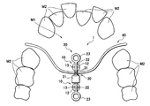
- FIG. 1 shows a configuration of an orthodontic implant device 1 according to an embodiment of the present invention.
- the orthodontic implant device 1 includes a pair of anchor members 10 fixed to the oral cavity, specifically, the palate M1, and a bridge member 20 disposed so as to connect the pair of anchor members 10. And a disposing member 30 disposed on the bridge member 20.
- the orthodontic implant device 1 may also include an extension arm 40 made of a wire and fixed to the tooth M2 to move the tooth M2.
- FIG. 2 shows the structure of the anchor member 10.
- FIG. 2A illustrates a configuration viewed from the side
- FIG. 2B illustrates a configuration viewed from above.
- the pair of anchor members 10 is made of, for example, a titanium alloy, and includes a shaft 11 on which a screw thread is formed, and a head portion 12 formed on one end portion of the shaft 11.
- a straight head groove 13 is formed on the opposite side of the head 12 from the shaft 11.
- the head groove 13 is used to insert and rotate a tool such as a driver when the anchor member 10 is embedded in the palate M1, and the bridge member 20 is disposed after the anchor member 10 is embedded in the palate M1. It is used to do.
- the head groove 13 is preferably formed over the entire upper surface from the peripheral edge of the head 12 to the peripheral edge facing through the central portion. This is because the bridge member 20 is provided.
- the head groove 13 has, for example, a pair of side surfaces 13A and a bottom surface 13B therebetween, and is configured so that the pair of side surfaces 13A and the bottom surface 13B have a vertical relationship, that is, a relationship that intersects at right angles. It is preferable.
- the cross-sectional shape in a plane perpendicular to the extending direction of the head groove 13 is preferably configured to be a rectangle.
- the rectangle includes a square.
- the head groove 13 may be, for example, one strip, but it is preferable that two strips are formed so as to be orthogonal to each other at the center of the head 12. This is because it is easy to adjust the head grooves 13 of the pair of anchor members 10 so as to be positioned on the same straight line in order to dispose the bridge member 20.
- FIG. 3 shows a state in which the bridge member 20 is disposed on the anchor member 10.
- 3A illustrates a cross-sectional configuration viewed from the side
- FIG. 3B illustrates a configuration viewed from above.
- the anchor member 10 is preferably provided with a through-hole 15 for passing the ligature wire 14 on the head 12 side of the shaft 11.
- the bridge member 20 can be easily fixed by ligating the anchor member 10 and the bridge member 20 with the ligature wire 14 passed through the through hole 15. It is.
- the through hole 15 is provided, for example, so as to penetrate the shaft 11 in the width direction. Note that the ligature wire 14 is omitted in FIG.
- FIG. 4 shows the structure of the bridge member 20.
- 4A shows a configuration viewed from above
- FIG. 4B shows a cross-sectional configuration along the line II shown in FIG. 4A
- FIG. 4C shows FIG. 4D represents a cross-sectional configuration taken along line II-II shown in FIG. 4D
- the bridge member 20 is made of, for example, titanium, a titanium alloy, or stainless steel.
- the bridge member 20 is connected to the connection member 21 and the heads of the pair of anchor members 10. It has a pair of square wire-like portions 22 that fit into the groove 13.
- the connection part 21 is configured in a rectangular parallelepiped shape, for example.
- the rectangular parallelepiped includes a cube.
- connection portion 21 is provided with, for example, an insertion hole 21A for inserting a later-described protrusion 32 of the arrangement member 30.
- the insertion holes 21A are preferably provided at a plurality of locations by changing the extending direction.
- the insertion holes 21A are preferably provided extending in the extending direction of the pair of square wire-like portions 22 and in the vertical direction thereof. This is because the connection direction of the disposing member 30 can be changed according to the treatment content.
- the square wire-like portion 22 is configured in a square wire shape that fits the head groove 13, for example. This is because by fitting in the head groove 13, the wobbling can be suppressed and the head groove 13 can be stably arranged. Moreover, it is preferable that the square wire-like part 22 is fixed to the anchor member 10 by, for example, a ligature wire 14 passed through the through hole 15 and further fixed to the anchor member 10 by a bonding agent (not shown) as reinforcement.
- a bonding agent for example, a plastic such as a photo-curing resin is preferably exemplified.
- an annular portion 23 formed in a ring shape is preferably provided at an end portion of each square wire-shaped portion 22 opposite to the connection portion 21.
- the annular portion 23 is an advantageous structure for fixing an orthodontic device such as an elastic or a ligature wire, and is intended to reduce harmfulness in the oral cavity.
- the annular portion 23 may not be a complete ring shape, and the ring may be partially cut.
- FIG. 5 shows the configuration of the arrangement member 30.
- 5A shows a configuration viewed from above
- FIG. 5B shows a configuration viewed from the side
- FIG. 5C shows a state in which the extension arm 40 is fixed to the arrangement member 30.
- the disposing member 30 is made of, for example, stainless steel, and includes a fixing portion 31 for fixing the extension arm 40, and a wire-like protrusion 32 for disposing the fixing portion 31 on the bridge member 20. have.
- the arrangement member 30 may be provided with a hook portion for hooking a ligature wire when ligating.
- the fixing portion 31 has a fixing groove 31A, and can be fixed by fitting and caulking a part of the extension arm 40 to the fixing groove 31A.
- the fixing groove 31A has, for example, a pair of side surfaces 31B and a bottom surface 31C therebetween, and is configured so that the pair of side surfaces 31B and the bottom surface 31C have a vertical relationship, that is, a relationship that intersects at right angles. Is preferred. This is because at least a part of the extension arm 40 is constituted by a square wire, and the square wire portion is fitted in the fixing groove 31A, thereby suppressing wobble and stably fixing. It is preferable that a locking portion 31D is provided on the upper side of the pair of side surfaces 31B so as to protrude inward. This is because the extension arm 40 can be fixed more stably.
- the number of the protrusions 32 may be one, but it is preferable that a plurality of protrusions 32 are provided at intervals, for example, it is preferable that two protrusions 32 are provided in parallel at intervals. This is because the arrangement member 30 can be prevented from rotating and wobbling due to the deflection of the protrusion 32, and can be stably arranged.
- the connection portion 21 of the bridge member 20 is provided with a plurality of insertion holes 21 ⁇ / b> A at intervals corresponding to the protrusions 32.
- the insertion holes 21A are provided at a plurality of locations by changing the extension direction, it is preferable to provide a plurality of insertion holes 21A corresponding to the protrusions 32 in each extension direction.
- the protrusions 32 may be round wire or square wire, but it is more preferable that the protrusions 32 be square wire. This is because the insertion hole 21 ⁇ / b> A of the bridge member 20 can be arranged more stably by making it a prismatic shape that fits the protrusion 32.
- the protrusions 32 have a square wire shape, and the insertion hole 21 ⁇ / b> A of the bridge member 20 has a prismatic shape that fits the protrusions 32. This is to prevent the arrangement member 30 from rotating.
- FIG. 6 shows the configuration of the extension arm 40.
- the extension arm 40 may be made of, for example, stainless steel, but may be made of a superelastic alloy such as a nickel titanium alloy, and can be appropriately selected according to the content of treatment. This is because it can be fixed by being fitted into the fixing groove 31 and caulked, so that there is no heating step such as brazing and a material that is weak against heat can be used.
- the extension arm 40 is preferably composed of, for example, a square wire, but the portion that fits into the fixing groove 31 may be composed of a square wire, and the tip may be a round wire.
- the extension arm 40 may have any shape, and is determined according to the treatment content.
- the extension arm 40 may be created by a dentist or the like according to the treatment content.
- the orthodontic implant device 1 is used as follows, for example. First, as shown in FIG. 7, for example, a pair of anchor members 10 is embedded in the palate M1 of a patient who performs orthodontics. Specifically, for example, a tool such as a driver is inserted into the head groove 13 and the anchor member 10 is rotated to be embedded. At that time, it is preferable to finally adjust the head grooves 13 of the pair of anchor members 10 so as to be positioned on the same straight line. In addition, even if the head groove
- the bridge member 20 is prepared and fixed to the pair of anchor members 10. Specifically, for example, the pair of square wire-like portions 22 of the bridge member 20 are fitted in the head grooves 13 of the pair of anchor members 10 and fixed by the ligature wires 14. When the head grooves 13 of the pair of anchor members 10 are deviated from the same straight line, the pair of square wire portions 22 of the bridge member 20 can be bent and fitted to the head grooves 13.
- an extension arm 40 is prepared, and fixed by fitting into the fixing groove 31 ⁇ / b> A of the arrangement member 30 and crimping.
- the protruding portion 32 of the arrangement member 30 is inserted into the insertion hole 21 ⁇ / b> A of the bridge member 20 and fixed with a ligature wire (not shown).
- the extension arm 40 is fixed to the tooth M2 to be moved. Thereby, orthodontics is performed.
- the extension arm 40 is replaced. That is, the arrangement member 30 to which the extension arm 40 is fixed is extracted from the bridge member 20, and the new extension arm 40 is fixed to the arrangement member 30 and inserted into the bridge member 20.
- the disposing member having the fixing portion 31 for fixing the extension arm 40 and the wire-shaped protrusion 32 for disposing the fixing portion 31 on the bridge member 20.
- 30 and the fixing portion 31 is formed with a fixing groove 31A in which the side surface 31B and the bottom surface 31C are perpendicular to each other, and a part of the extension arm 40 is fitted and caulked to be fixed.
- the arm 40 can be made of a superelastic alloy which is weak against heat, and the range of material selection can be expanded. Moreover, even if the size of the member is small, it can be easily fixed, and labor can be reduced.
- the arrangement member 30 can be prevented from rotating and wobbling. , Can be disposed stably.
- FIG. 10 shows the configuration of the arrangement member 30 according to the first modification of the present invention.
- 10A shows a configuration viewed from above
- FIG. 10B shows a configuration viewed from the side
- FIG. 10C shows a state in which the extension arm 40 is fixed to the arrangement member 30.
- the arrangement member 30 is provided with a plurality of, for example, two fixing portions 31 at intervals. Others are the same as in the embodiment described above. If comprised in this way, the protrusion part 32 of the arrangement
- FIG. 11 shows the configuration of the bridge member 20 according to the second modification of the present invention.
- 11A shows a configuration viewed from above
- FIG. 11B shows a cross-sectional configuration along the line III-III shown in FIG. 11A
- FIG. 11C viewed from the side. Represents the configuration.
- the bridge member 20 is provided with a curved portion 24 that is curved to protrude toward the opposite side of the connecting portion 21 instead of the annular portion 23 at the end of the rectangular wire-shaped portion 22.
- the curved portion 24 is, for example, wider than the square wire-like portion 22, is provided to protrude on both sides, and is preferably formed in a bowl shape. Even if comprised in this way, like the annular part 23, while being able to fix correction
- the bending portion 24 may be provided with a hole 24A for fixing a correction device such as elastic or ligature wire.
- FIG. 11 shows the case where the curved portion 24 is provided at the end of one square wire-like portion 22 and the annular portion 23 is provided at the end of the other square wire-like portion 22.
- the rear part is circular so as not to hinder, and both may be curved parts 24 depending on the case.
- the bridge member 20 may be provided with, for example, a locking portion 21B that protrudes from the connecting portion 21 and fixes a correction device such as an elastic or a ligature.
- a correction device such as an elastic or a ligature.
- two locking portions 21 ⁇ / b> B are provided on both sides in the extending direction of the pair of square wire-shaped portions 22.
- Other configurations are the same as those of the above-described embodiment.
- the present invention has been described above with reference to the embodiment. However, the present invention is not limited to the above embodiment, and various modifications can be made.
- each component has been specifically described. However, not all the components may be provided, and other components may be provided. Each component may have other configurations.
- the portion for fixing the anchor member 10 is not limited to the palate M1, and can be fixed to a portion where the attached gingiva is present in the oral cavity and does not hinder the movement of the tooth, for example, the edentulous jaw alveolar crest It is.
Landscapes
- Health & Medical Sciences (AREA)
- Oral & Maxillofacial Surgery (AREA)
- Dentistry (AREA)
- Epidemiology (AREA)
- Life Sciences & Earth Sciences (AREA)
- Animal Behavior & Ethology (AREA)
- General Health & Medical Sciences (AREA)
- Public Health (AREA)
- Veterinary Medicine (AREA)
- Orthopedic Medicine & Surgery (AREA)
- Dental Tools And Instruments Or Auxiliary Dental Instruments (AREA)
Abstract
【課題】容易に作成することができ、かつ、エクステンションアームを構成する材料選択の幅を広げることができる歯列矯正用インプラント装置を提供する。 【解決手段】口蓋M1に固定される一対のアンカー部材10と、一対のアンカー部材10の間を結ぶように配設されるブリッジ部材20と、ブリッジ部材20に配設される配設部材30と、歯M2を移動させるエクステンションアーム40とを備える。配設部材30は、エクステンションアーム40を固定するための固定部31と、この固定部31をブリッジ部材20に配設するためのワイヤ状の突起部とを有している。
Description
本発明は、口腔内に固定して歯を移動させるための歯列矯正用インプラント装置に関する。
矯正治療において固定源の確保は治療を成功に導く為の重要な要素であり、従来これを強化するために顎内固定や顎外固定など様々な装置が用いられてきた。しかしそれらの装置はその効果が患者の協力度に依存する欠点があった。そこで近年、骨を固定源(インプラントアンカー)として歯を移動させる方法が考案され、マルチブラケットシステムの一部に組み込まれる装置として急速に普及した。インプラントアンカーとしては、スクリュー型のものが安価で簡便であり、埋め込み時の外科的侵襲が非常に小さいことから広く使用されている。しかし、スクリュー型のインプラントアンカーは、埋め込み位置に制限があり、また、脱落してしまう場合があるという問題があった。特に、上顎の頬側は、隣接歯の歯根の近接、上顎洞の歯根間への張り出し、付着歯肉幅が狭いなどの理由から埋め込み位置が制限されることが多い。また、狭い歯根間の歯槽骨に埋込できたとしても、その存在が歯の移動を制限してしまう場合がある。更に、骨質が悪いと脱落率が増加してしまい、埋め込み時の歯根損傷とそれに伴うインプラントアンカーの脱落や、遊離歯肉部位への埋め込み時におこるインプラントアンカー頭部の歯肉への埋没など問題が多い。
そこで、近年では、スクリュー型のインプラントアンカーを骨質がよく、歯の移動に制限のない口蓋に埋め込んだ歯列矯正用インプラント装置が提案されている。例えば、本願出願人は、口腔内に固定される一対のアンカー部材と、この一対のアンカー部材の間を結ぶように伸長して形成され、一対のアンカー部材に固定されるブリッジ部材と、このブリッジ部材に配設され、角ワイヤを挿入可能な角柱状受部が設けられており、この角柱状受部にエクステンションアームの一部が挿入されて接続される接続部材とを備えた歯列矯正用インプラント装置を開発した(特許文献1参照)。この歯列矯正用インプラント装置によれば、角柱状受部に、エクステンションアームの角ワイヤよりなる挿入部を挿入することにより、回転することなく安定してエクステンションアームを口腔内に固定することができる。
しかしながら、従来は、例えば、歯に対して固定して歯を移動させるワイヤよりなるアーム部に、角ワイヤよりなる挿入部をろう着などで接合していたので、ニッケル・チタン合金等の超弾性合金によりアーム部を構成しようとしても、ろう着時の加熱により弾性が失われてしまうという問題があった。また、アーム部に接合する挿入部は非常に小さいので、特に、歯科医師が治療内容に応じてアーム部を作成する場合等、ろう着は面倒であり、手間がかかるという問題もあった。
本発明は、このような問題に基づきなされたものであり、容易に作成することができ、かつ、エクステンションアームを構成する材料選択の幅を広げることができる歯列矯正用インプラント装置を提供することを目的とする。
本発明の歯列矯正用インプラント装置は、口腔内に固定し、歯を移動させるためのワイヤよりなるエクステンションアームを接続して歯列矯正を行うものであって、口腔内に固定され、ねじ山が形成された軸と、この軸の一端部に形成された頭部とを有し、この頭部に、側面と底面とが垂直の関係を有する頭部溝が形成された一対のアンカー部材と、この一対のアンカー部材の間を結ぶように配設されるブリッジ部材と、エクステンションアームを固定するための固定部と、この固定部をブリッジ部材に配設するためのワイヤ状の突起部とを有する配設部材とを備え、ブリッジ部材は、突起部を挿入する挿入孔が設けられた接続部と、この接続部に配設され、一対のアンカー部材の頭部溝にはめ合わせる一対の角ワイヤ状部とを有し、固定部は、側面と底面とが垂直の関係を有する固定溝を有し、エクステンションアームの一部を嵌め合わせてかしめることにより固定するものである。
本発明の他の歯列矯正用インプラント装置は、ワイヤよりなり、歯に対して固定して歯を移動させるエクステンションアームと、口腔内に固定され、ねじ山が形成された軸と、この軸の一端部に形成された頭部とを有し、この頭部に、側面と底面とが垂直の関係を有する頭部溝が形成された一対のアンカー部材と、この一対のアンカー部材の間を結ぶように配設されるブリッジ部材と、エクステンションアームを固定するための固定部と、この固定部をブリッジ部材に配設するためのワイヤ状の突起部とを有する配設部材とを備え、ブリッジ部材は、突起部を挿入する挿入孔が設けられた接続部と、この接続部に配設され、一対のアンカー部材の頭部溝にはめ合わせる一対の角ワイヤ状部とを有し、固定部は、側面と底面とが垂直の関係を有する固定溝を有し、エクステンションアームの一部を嵌め合わせてかしめることにより固定するものである。
本発明の歯列矯正用インプラント装置によれば、エクステンションアームを固定するための固定部と、この固定部をブリッジ部材に配設するためのワイヤ状の突起部とを有する配設部材を備え、固定部には側面と底面とが垂直の関係を有する固定溝を形成し、エクステンションアームの一部を嵌め合わせてかしめることにより固定するようにしたので、エクステンションアームを熱に弱い超弾性合金等により構成することもでき、材料選択の幅を広げることができる。また、部材の大きさが小さくても容易に固定することができ、手間を軽減することができる。
また、配設部材に突起部を複数設けると共に、ブリッジ部材の接続部に挿入孔を複数設けるようにすれば、配設部材が回転してぐらつくことを抑制することができ、安定して配設することができる。
更に、配設部材に固定部を複数設けるようにすれば、配設部材の突起部をブリッジ部材の挿入孔に挿入し、例えば、各固定部の間に結紮線を通して、結紮線により配設部材とブリッジ部材とを容易に固定することができる。よって、結紮線を引掛けるための引掛け部を特別に設ける必要がなく、構成を簡素化することができる。
以下、本発明の実施の形態について、図面を参照して詳細に説明する。
(一実施の形態)
図1は、本発明の一実施の形態に係る歯列矯正用インプラント装置1の構成を表すものである。この歯列矯正用インプラント装置1は、口腔内、具体的には口蓋M1に固定される一対のアンカー部材10と、この一対のアンカー部材10の間を結ぶように配設されるブリッジ部材20と、このブリッジ部材20に配設される配設部材30とを備えている。この歯列矯正用インプラント装置1は、また、ワイヤよりなり、歯M2に対して固定して、歯M2を移動させるエクステンションアーム40を備えていてもよい。
図1は、本発明の一実施の形態に係る歯列矯正用インプラント装置1の構成を表すものである。この歯列矯正用インプラント装置1は、口腔内、具体的には口蓋M1に固定される一対のアンカー部材10と、この一対のアンカー部材10の間を結ぶように配設されるブリッジ部材20と、このブリッジ部材20に配設される配設部材30とを備えている。この歯列矯正用インプラント装置1は、また、ワイヤよりなり、歯M2に対して固定して、歯M2を移動させるエクステンションアーム40を備えていてもよい。
図2は、アンカー部材10の構成を表すものである。図2(A)は横から見た構成を表し、図2(B)は上から見た構成を表している。一対のアンカー部材10は、例えば、チタニウム合金により構成されており、ねじ山が形成された軸11と、この軸11の一端部に形成された頭部12とを有している。頭部12の軸11と反対側には、直線状の頭部溝13が形成されている。頭部溝13は、アンカー部材10を口蓋M1に埋め込む際に、ドライバなどの道具を挿入して回転させるために用いられると共に、アンカー部材10を口蓋M1に埋め込んだ後に、ブリッジ部材20を配設するために用いられるものである。頭部溝13は、頭部12の周縁部から中央部を通り対向する周縁部まで上部全面にわたって形成されていることが好ましい。ブリッジ部材20を配設するためである。
頭部溝13は、例えば、一対の側面13Aとその間の底面13Bとを有しており、一対の側面13Aと底面13Bとが垂直の関係、すなわち直角に交わる関係を有するように構成されていることが好ましい。例えば、頭部溝13の伸長方向に対して垂直な面における断面形状は長方形となるように構成されていることが好ましい。なお、長方形には正方形を含む。頭部溝13は、例えば、1条であってもよいが、頭部12の中央部において直交するように2条形成されていることが好ましい。ブリッジ部材20を配設するために一対のアンカー部材10の頭部溝13が同一直線上に位置するように調節しやすいからである。
図3は、アンカー部材10にブリッジ部材20を配設した状態を表すものである。図3(A)は横から見た断面構成を表し、図3(B)は上から見た構成を表している。アンカー部材10には、軸11の頭部12の側に、結紮線14を通すための貫通孔15が設けられていることが好ましい。頭部溝13にブリッジ部材20を配設したのち、貫通孔15に通した結紮線14でアンカー部材10とブリッジ部材20とを結紮することにより、容易にブリッジ部材20を固定することができるからである。貫通孔15は、例えば、軸11を幅方向に貫通するように設けられている。なお、結紮線14は、図1においては省略している。
図4は、ブリッジ部材20の構成を表すものである。図4(A)は上から見た構成を表し、図4(B)は図4(A)に示したI-I線に沿った断面構成を表し、図4(C)は図4(A)に示したII-II線に沿った断面構成を表し、図4(D)は横から見た構成を表している。ブリッジ部材20は、例えば、チタン、チタン合金、又は、ステンレススチールにより構成されており、配設部材30を接続する接続部21と、この接続部21に配設され、一対のアンカー部材10の頭部溝13に嵌め合せる一対の角ワイヤ状部22とを有している。接続部21は、例えば、直方体状に構成されている。なお、直方体には立方体も含む。
接続部21には、例えば、配設部材30の後述する突起部32を挿入するための挿入孔21Aが設けられている。挿入孔21Aは、伸長方向を変えて複数箇所に設けることが好ましく、例えば、一対の角ワイヤ状部22の伸長方向と、その垂直方向にそれぞれ伸長して設けることが好ましい。治療内容に応じて、配設部材30の接続方向を変えることができるようにするためである。
角ワイヤ状部22は、例えば、頭部溝13に適合する角ワイヤ状に構成されている。頭部溝13に嵌め合せることにより、ぐらつきを抑制して安定して配設することができるからである。また、角ワイヤ状部22は、例えば、貫通孔15に通した結紮線14によりアンカー部材10に固定され、更に、補強として図示しない接合剤によりアンカー部材10に固定されることが好ましい。接合剤としては、例えば、光硬化樹脂などのプラスチックが好ましく挙げられる。各角ワイヤ状部22の接続部21と反対側の端部には、例えば、リング状に形成された環状部23が設けられていることが好ましい。環状部23は、エラスティックや結紮線などの矯正装置を固定するために有利な構造であると共に、口腔内での為害性を低くするためのものある。なお、環状部23は、完全なリング状でなくてもよく、一部において環が切断されていてもよい。
図5は、配設部材30の構成を表すものである。図5(A)は上から見た構成を表し、図5(B)は横から見た構成を表し、図5(C)は配設部材30にエクステンションアーム40を固定した状態を表している。配設部材30は、例えば、ステンレススチールにより構成されており、エクステンションアーム40を固定するための固定部31と、この固定部31をブリッジ部材20に配設するためのワイヤ状の突起部32とを有している。なお、配設部材30には、結紮する際に、結紮線を引掛ける引掛け部が設けられていてもよい。
固定部31は、固定溝31Aを有しており、固定溝31Aにエクステンションアーム40の一部を嵌め合わせてかしめることにより固定することができるようになっている。固定溝31Aは、例えば、一対の側面31Bとその間の底面31Cとを有しており、一対の側面31Bと底面31Cとが垂直の関係、すなわち直角に交わる関係を有するように構成されていることが好ましい。エクステンションアーム40の少なくとも一部を角ワイヤで構成し、この角ワイヤ部分を固定溝31Aに嵌め合せることにより、ぐらつきを抑制し、安定して固定することができるからである。一対の側面31Bの上側には、内側に突出して係止部31Dがそれぞれ設けられていることが好ましい。エクステンションアーム40をより安定して固定することができるからである。
突起部32は、1本でもよいが、間隔を開けて複数設けられることが好ましく、例えば、間隔を開けて平行に2本設けられることが好ましい。配設部材30が突起部32のたわみにより回転してぐらつくことを抑制することができ、安定して配設することができるからである。これに合わせて、ブリッジ部材20の接続部21には、突起部32に対応して、挿入孔21Aが間隔を開けて複数設けられていることが好ましい。また、例えば、伸長方向を変えて挿入孔21Aを複数箇所に設ける場合には、各伸長方向について、突起部32に対応して、挿入孔21Aを複数本ずつ設けることが好ましい。
突起部32を複数本設ける場合には、突起部32は丸ワイヤ状でも、角ワイヤ状でもよいが、角ワイヤ状とすればより好ましい。ブリッジ部材20の挿入孔21Aを突起部32に適合する角柱状とすることにより、より安定して配設することができるからである。なお、突起部32を1本とする場合には、突起部32は角ワイヤ状とし、ブリッジ部材20の挿入孔21Aを突起部32に適合する角柱状とすることが好ましい。配設部材30の回転を抑制するためである。
図6はエクステンションアーム40の構成を表すものである。エクステンションアーム40は、例えば、ステンレススチールにより構成してもよいが、ニッケルチタン合金などの超弾性合金により構成してもよく、治療内容に応じて適宜選択することができる。固定溝31に嵌め合わせてかしめることにより固定することができるので、ろう着などの加熱工程がなく、熱に弱い材料でも用いることができるからである。エクステンションアーム40は、例えば、角ワイヤにより構成することが好ましいが、固定溝31に嵌め合わせる部分を角ワイヤにより構成し、その先は丸ワイヤとなるようにしてもよい。エクステンションアーム40の形状はどのようなものでもよく、治療内容に応じて決定される。なお、エクステンションアーム40は、治療内容に応じて、歯科医師などが作成してもよい。
この歯列矯正用インプラント装置1は、例えば、次のようにして用いられる。まず、例えば、図7に示したように、歯列矯正を行う患者の口蓋M1に一対のアンカー部材10を埋め込む。具体的には、例えば、ドライバなどの道具を頭部溝13に挿入して、アンカー部材10を回転させることにより埋め込む。その際、最終的に、一対のアンカー部材10の頭部溝13が同一直線上に位置するように調節することが好ましい。なお、一対のアンカー部材10の頭部溝13が同一直線上からずれていても、後述する手順において対応することは可能である。
次いで、例えば、図8に示したように、ブリッジ部材20を用意し、一対のアンカー部材10に固定する。具体的には、例えば、一対のアンカー部材10の頭部溝13に、ブリッジ部材20の一対の角ワイヤ状部22を嵌め合わせ、結紮線14により固定する。なお、一対のアンカー部材10の頭部溝13が同一直線上からずれている場合には、ブリッジ部材20の一対の角ワイヤ状部22を屈曲させて頭部溝13に嵌め合わせることができる。
続いて、例えば、図9に示したように、エクステンションアーム40を用意し、配設部材30の固定溝31Aに嵌め合わせてかしめることにより固定する。次に、例えば、図1に示したように、配設部材30の突起部32をブリッジ部材20の挿入孔21Aに挿入し、図示しない結紮線で固定する。また、エクステンションアーム40は、移動させる歯M2に固定する。これにより、歯列矯正が行われる。
なお、治療の進行状況に応じて、エクステンションアーム40の形状を変更する必要がある場合には、エクステンションアーム40を交換する。すなわち、エクステンションアーム40が固定されている配設部材30をブリッジ部材20から抜き取り、新しいエクステンションアーム40を配設部材30に固定して、ブリッジ部材20に挿入する。
このように本実施の形態によれば、エクステンションアーム40を固定するための固定部31と、この固定部31をブリッジ部材20に配設するためのワイヤ状の突起部32とを有する配設部材30を備え、固定部31には側面31Bと底面31Cとが垂直の関係を有する固定溝31Aを形成し、エクステンションアーム40の一部を嵌め合わせてかしめることにより固定するようにしたので、エクステンションアーム40を熱に弱い超弾性合金等により構成することもでき、材料選択の幅を広げることができる。また、部材の大きさが小さくても容易に固定することができ、手間を軽減することができる。
また、配設部材30に突起部32を複数設けると共に、ブリッジ部材20の接続部21に挿入孔21Aを複数設けるようにすれば、配設部材30が回転してぐらつくことを抑制することができ、安定して配設することができる。
(変形例1)
図10は、本発明の変形例1に係る配設部材30の構成を表すものである。図10(A)は上から見た構成を表し、図10(B)は横から見た構成を表し、図10(C)は配設部材30にエクステンションアーム40を固定した状態を表している。この配設部材30は、固定部31が間隔を開けて複数、例えば2個設けられたものである。他は上述した一実施の形態と同様である。このように構成すれば、配設部材30の突起部32をブリッジ部材20の挿入孔21Aに挿入し、各固定部31の間に図示しない結紮線を通して、結紮線により配設部材30とブリッジ部材20とを容易に固定することができる。よって、結紮線を引掛けるための引掛け部を特別に設ける必要がなく、構成を簡素化することができる。
図10は、本発明の変形例1に係る配設部材30の構成を表すものである。図10(A)は上から見た構成を表し、図10(B)は横から見た構成を表し、図10(C)は配設部材30にエクステンションアーム40を固定した状態を表している。この配設部材30は、固定部31が間隔を開けて複数、例えば2個設けられたものである。他は上述した一実施の形態と同様である。このように構成すれば、配設部材30の突起部32をブリッジ部材20の挿入孔21Aに挿入し、各固定部31の間に図示しない結紮線を通して、結紮線により配設部材30とブリッジ部材20とを容易に固定することができる。よって、結紮線を引掛けるための引掛け部を特別に設ける必要がなく、構成を簡素化することができる。
(変形例2)
図11は、本発明の変形例2に係るブリッジ部材20の構成を表すものである。図11(A)は上から見た構成を表し、図11(B)は図11(A)に示したIII-III線に沿った断面構成を表し、図11(C)は横から見た構成を表している。
図11は、本発明の変形例2に係るブリッジ部材20の構成を表すものである。図11(A)は上から見た構成を表し、図11(B)は図11(A)に示したIII-III線に沿った断面構成を表し、図11(C)は横から見た構成を表している。
このブリッジ部材20は、角ワイヤ状部22の端部に、環状部23に変えて、接続部21と反対側に向かい突出するように湾曲された湾曲部24が設けられている。この湾曲部24は、例えば、角ワイヤ状部22よりも幅が広く、両側に突出して設けられており、錨状に形成されていることが好ましい。このように構成しても、環状部23と同様に、エラスティックや結紮線などの矯正装置を固定することができると共に、口腔内での為害性を低くすることができるので好ましい。湾曲部24には、エラスティックや結紮線などの矯正装置を固定するための孔24Aを設けるようにしてもよい。なお、図11では、一方の角ワイヤ状部22の端部に湾曲部24を設け、他方の角ワイヤ状部22の端部に環状部23を設ける場合について示したが、これは食物の流れを妨げぬよう後方部を円形としたもので、症例に応じて両方とも湾曲部24としてもよい。
また、このブリッジ部材20には、例えば、接続部21から突出して、エラスティックや結紮線などの矯正装置を固定する係止部21Bが設けられていてもよい。係止部21Bは、例えば、一対の角ワイヤ状部22の伸長方向の両側に2個ずつ設けられていることが好ましい。他の構成は上述した一実施の形態と同様である。
以上、実施の形態を挙げて本発明を説明したが、本発明は上記実施の形態に限定されるものではなく、種々変形可能である。例えば、上記実施の形態では、各構成要素について具体的に説明したが、全ての構成要素を備えていなくてもよく、また、他の構成要素を備えていてもよい。また、各構成要素は、他の構成を備えていてもよい。また、アンカー部材10を固定する部位も、口蓋M1に限定されるものではなく、口腔内において付着歯肉が存在し歯の移動に支障がない部位、例えば、無歯顎部歯槽頂にも固定可能である。
歯列矯正に用いることができる。
1…歯列矯正用インプラント装置、10…アンカー部材、11…軸、12…頭部、13…頭部溝、13A…側面、13B…底面、14…結紮線、15…貫通孔、20…ブリッジ部材、21…接続部、21A…挿入孔、21B…係止部、22…角ワイヤ状部、23…環状部、24…湾曲部、24A…孔、30…配設部材、31…固定部、31A…固定溝、31B…側面、31C…底面、31D…係止部、32…突起部、40…エクステンションアーム
Claims (6)
- 口腔内に固定し、歯を移動させるためのワイヤよりなるエクステンションアームを接続して歯列矯正を行う歯列矯正用インプラント装置であって、
口腔内に固定され、ねじ山が形成された軸と、この軸の一端部に形成された頭部とを有し、この頭部に、側面と底面とが垂直の関係を有する頭部溝が形成された一対のアンカー部材と、
この一対のアンカー部材の間を結ぶように配設されるブリッジ部材と、
前記エクステンションアームを固定するための固定部と、この固定部を前記ブリッジ部材に配設するためのワイヤ状の突起部とを有する配設部材とを備え、
前記ブリッジ部材は、前記突起部を挿入する挿入孔が設けられた接続部と、この接続部に配設され、前記一対のアンカー部材の頭部溝にはめ合わせる一対の角ワイヤ状部とを有し、
前記固定部は、一対の側面と底面とが垂直の関係を有する固定溝を有し、前記一対の側面の上側には内側に突出して係止部がそれぞれ設けられ、前記エクステンションアームの一部を嵌め合わせてかしめることにより固定する
ことを特徴とする歯列矯正用インプラント装置。 - 前記配設部材には、前記突起部が間隔を開けて複数設けられ、
前記ブリッジ部材の前記接続部には、前記突起部に対応して、前記挿入孔が間隔を開けて複数設けられた
ことを特徴とする請求項1記載の歯列矯正用インプラント装置。 - 前記配設部材には、前記固定部が間隔を開けて複数設けられた
ことを特徴とする請求項1記載の歯列矯正用インプラント装置。 - ワイヤよりなり、歯に対して固定して歯を移動させるエクステンションアームと、
口腔内に固定され、ねじ山が形成された軸と、この軸の一端部に形成された頭部とを有し、この頭部に、側面と底面とが垂直の関係を有する頭部溝が形成された一対のアンカー部材と、
この一対のアンカー部材の間を結ぶように配設されるブリッジ部材と、
前記エクステンションアームを固定するための固定部と、この固定部を前記ブリッジ部材に配設するためのワイヤ状の突起部とを有する配設部材とを備え、
前記ブリッジ部材は、前記突起部を挿入する挿入孔が設けられた接続部と、この接続部に配設され、前記一対のアンカー部材の頭部溝にはめ合わせる一対の角ワイヤ状部とを有し、
前記固定部は、一対の側面と底面とが垂直の関係を有する固定溝を有し、前記一対の側面の上側には内側に突出して係止部がそれぞれ設けられ、前記エクステンションアームの一部を嵌め合わせてかしめることにより固定する
ことを特徴とする歯列矯正用インプラント装置。 - 前記配設部材には、前記突起部が間隔を開けて複数設けられ、
前記ブリッジ部材の前記接続部には、前記突起部に対応して、前記挿入孔が間隔を開けて複数設けられた
ことを特徴とする請求項4記載の歯列矯正用インプラント装置。 - 前記配設部材には、前記固定部が間隔を開けて複数設けられた
ことを特徴とする請求項4記載の歯列矯正用インプラント装置。
Priority Applications (3)
| Application Number | Priority Date | Filing Date | Title |
|---|---|---|---|
| EP17848775.7A EP3510966B1 (en) | 2016-09-10 | 2017-09-05 | Orthodontic implant device |
| KR1020187027499A KR101913233B1 (ko) | 2016-09-10 | 2017-09-05 | 치열교정용 임플란트장치 |
| US16/211,423 US10993789B2 (en) | 2016-09-10 | 2018-12-06 | Orthodontic implant device |
Applications Claiming Priority (2)
| Application Number | Priority Date | Filing Date | Title |
|---|---|---|---|
| JP2016177178A JP6185130B1 (ja) | 2016-09-10 | 2016-09-10 | 歯列矯正用インプラント装置 |
| JP2016-177178 | 2016-09-10 |
Related Child Applications (1)
| Application Number | Title | Priority Date | Filing Date |
|---|---|---|---|
| US16/211,423 Continuation US10993789B2 (en) | 2016-09-10 | 2018-12-06 | Orthodontic implant device |
Publications (1)
| Publication Number | Publication Date |
|---|---|
| WO2018047835A1 true WO2018047835A1 (ja) | 2018-03-15 |
Family
ID=59678185
Family Applications (1)
| Application Number | Title | Priority Date | Filing Date |
|---|---|---|---|
| PCT/JP2017/032006 Ceased WO2018047835A1 (ja) | 2016-09-10 | 2017-09-05 | 歯列矯正用インプラント装置 |
Country Status (5)
| Country | Link |
|---|---|
| US (1) | US10993789B2 (ja) |
| EP (1) | EP3510966B1 (ja) |
| JP (1) | JP6185130B1 (ja) |
| KR (1) | KR101913233B1 (ja) |
| WO (1) | WO2018047835A1 (ja) |
Families Citing this family (1)
| Publication number | Priority date | Publication date | Assignee | Title |
|---|---|---|---|---|
| JP2020146224A (ja) * | 2019-03-13 | 2020-09-17 | 学校法人日本大学 | 歯列矯正器具 |
Citations (5)
| Publication number | Priority date | Publication date | Assignee | Title |
|---|---|---|---|---|
| JPH11278002A (ja) * | 1998-03-31 | 1999-10-12 | Chuo Motor Wheel Co Ltd | 自動車用ホイールカバー |
| JP2002169126A (ja) * | 2000-11-30 | 2002-06-14 | Mitamura Noriaki | 眼鏡テンプルの連結構造 |
| JP2003311355A (ja) * | 2002-04-16 | 2003-11-05 | Olympus Optical Co Ltd | 金属ワイヤーの製造法 |
| JP2015083153A (ja) * | 2007-06-28 | 2015-04-30 | オルムコ コーポレイション | 自己結紮式歯科矯正用ブラケットおよび該ブラケットの設置装置 |
| JP2016036474A (ja) | 2014-08-07 | 2016-03-22 | 医療法人クリエイティングスマイルズ | 歯科矯正用インプラント装置 |
Family Cites Families (21)
| Publication number | Priority date | Publication date | Assignee | Title |
|---|---|---|---|---|
| JPS5577418A (en) * | 1978-12-06 | 1980-06-11 | Oishi Kikai Seisakusho:Kk | Method and device for controlling revolution orbit of endless band saw with diamond tip |
| US4639219A (en) * | 1982-02-22 | 1987-01-27 | American Orthodontics Corporation | Surgical ball hooks |
| US5967772A (en) * | 1998-12-09 | 1999-10-19 | Gray; James B. | Orthodontic anchor system |
| US6435870B1 (en) * | 2000-09-28 | 2002-08-20 | Kevin C. Walde | Orthodontic distalizing appliance |
| JP3486814B2 (ja) * | 2001-10-12 | 2004-01-13 | 三郎 山本 | 歯列矯正用ワイヤ部材およびワイヤ切断工具 |
| US7677887B2 (en) * | 2004-07-02 | 2010-03-16 | Nicholson James A | Shape memory self-ligating orthodontic brackets |
| WO2007128969A2 (en) * | 2006-04-25 | 2007-11-15 | D B Orthodontics Ltd | Orthodontic implant device |
| EP2083741A2 (en) * | 2006-10-10 | 2009-08-05 | Ormco Corporation | Orthodontic implant cap and orthodontic treatment assembly including same |
| JP4680209B2 (ja) | 2007-01-26 | 2011-05-11 | 康寛 斉宮 | 歯列矯正用のインプラント構造 |
| JP4058105B1 (ja) * | 2007-10-10 | 2008-03-05 | 寧 三谷 | 顎顔面用矯正器具 |
| DE202008007527U1 (de) * | 2008-06-05 | 2008-08-14 | Promedia A. Ahnfeldt Gmbh | Vorrichtung zur kieferorthopädischen Korrekturbehandlung, insbesondere zur Behebung der Fehlstellung von Backenzähnen |
| US20100015565A1 (en) * | 2008-06-13 | 2010-01-21 | Roberto J. Carrillo Gonzalez | Orthodontic Devices |
| IT1392605B1 (it) * | 2008-12-31 | 2012-03-09 | Hdc S R L | Dispositivo di fissaggio per apparecchi ortodontici |
| US20100190128A1 (en) * | 2009-01-23 | 2010-07-29 | Wool Arthur L | Orthodontic arch wire and method for using the same |
| US8113826B2 (en) * | 2009-04-09 | 2012-02-14 | Williams Michael O | Biased palatal bone expander |
| ITVI20090191A1 (it) * | 2009-07-27 | 2011-01-28 | Hdc S R L | Dispositivo ortodontico con un sistema di fissaggio auto-legante per apparecchi ortodontici con una parte filiforme |
| US20120202164A1 (en) * | 2011-02-09 | 2012-08-09 | Geo-Protector Technology Co., Ltd. | Orthodontic Maxillary Micro Implant |
| JP6257045B2 (ja) * | 2012-12-07 | 2018-01-17 | 国立大学法人 鹿児島大学 | スクリューの結合力維持具及び結合力維持具付きスクリュー |
| ITTV20120059U1 (it) * | 2012-12-19 | 2014-06-20 | Daniele Cantarella | Connettore per archi o fili ortodontici. |
| DE102015221550A1 (de) * | 2014-11-05 | 2016-05-12 | Visottica Industrie S.P.A. | Schnelle gaumennaht-erweiterungsapparatur und verfahren zu ihrer herstellung |
| EP3267926A1 (en) * | 2015-03-13 | 2018-01-17 | 3M Innovative Properties Company | Orthodontic appliance including arch member |
-
2016
- 2016-09-10 JP JP2016177178A patent/JP6185130B1/ja active Active
-
2017
- 2017-09-05 EP EP17848775.7A patent/EP3510966B1/en active Active
- 2017-09-05 KR KR1020187027499A patent/KR101913233B1/ko active Active
- 2017-09-05 WO PCT/JP2017/032006 patent/WO2018047835A1/ja not_active Ceased
-
2018
- 2018-12-06 US US16/211,423 patent/US10993789B2/en active Active
Patent Citations (5)
| Publication number | Priority date | Publication date | Assignee | Title |
|---|---|---|---|---|
| JPH11278002A (ja) * | 1998-03-31 | 1999-10-12 | Chuo Motor Wheel Co Ltd | 自動車用ホイールカバー |
| JP2002169126A (ja) * | 2000-11-30 | 2002-06-14 | Mitamura Noriaki | 眼鏡テンプルの連結構造 |
| JP2003311355A (ja) * | 2002-04-16 | 2003-11-05 | Olympus Optical Co Ltd | 金属ワイヤーの製造法 |
| JP2015083153A (ja) * | 2007-06-28 | 2015-04-30 | オルムコ コーポレイション | 自己結紮式歯科矯正用ブラケットおよび該ブラケットの設置装置 |
| JP2016036474A (ja) | 2014-08-07 | 2016-03-22 | 医療法人クリエイティングスマイルズ | 歯科矯正用インプラント装置 |
Non-Patent Citations (1)
| Title |
|---|
| See also references of EP3510966A4 * |
Also Published As
| Publication number | Publication date |
|---|---|
| JP2018038767A (ja) | 2018-03-15 |
| US10993789B2 (en) | 2021-05-04 |
| US20190105132A1 (en) | 2019-04-11 |
| JP6185130B1 (ja) | 2017-08-23 |
| KR101913233B1 (ko) | 2018-10-30 |
| KR20180110172A (ko) | 2018-10-08 |
| EP3510966A1 (en) | 2019-07-17 |
| EP3510966A4 (en) | 2020-08-05 |
| EP3510966B1 (en) | 2021-09-01 |
Similar Documents
| Publication | Publication Date | Title |
|---|---|---|
| JP7828306B2 (ja) | 非滑り歯列弓形態を伴う歯列矯正器具 | |
| EP3445273B1 (en) | Orthodontic appliance with non-sliding, tied archwire | |
| JP5884230B2 (ja) | 結合力維持具付きスクリュー | |
| US8235714B2 (en) | Convertible buccal tube orthodontic bracket | |
| JP5719365B2 (ja) | 口腔内歯列矯正装置 | |
| JP2005185705A (ja) | 歯科矯正用支持体 | |
| JP2006320726A (ja) | 改良型矯正用ブラケット | |
| JP2009072625A (ja) | 舌側ブラケット | |
| JP4554859B2 (ja) | ばねループリテーナ及びその製造方法 | |
| JP6185130B1 (ja) | 歯列矯正用インプラント装置 | |
| KR101551381B1 (ko) | 치과 교정술 또는 악안면 수술용 고정원 | |
| KR20150134632A (ko) | 치열 교정용 브라켓 | |
| KR101851106B1 (ko) | 설측용 치열 교정장치 | |
| US20130302744A1 (en) | Orthodontic separator | |
| JP2004081565A (ja) | 把持型歯科矯正固定装置 | |
| JP5728610B1 (ja) | 歯科矯正用インプラント装置 | |
| KR20160088032A (ko) | 구개고정용장치 | |
| JP2013141582A (ja) | 歯列矯正用インプラント | |
| KR102080210B1 (ko) | 치열교정용 브라켓 조립체 | |
| JP6664937B2 (ja) | ドーム型結合力維持具を備えたアンカースクリュー装置 | |
| JPS61220643A (ja) | 歯列矯正用ブラケツト | |
| KR102297927B1 (ko) | 치열교정용 브라켓 조립체 | |
| JP2020146224A (ja) | 歯列矯正器具 | |
| KR101919411B1 (ko) | 치아교정기 및 치아교정 어셈블리 | |
| KR200210731Y1 (ko) | 치아 교정용 임플란트 |
Legal Events
| Date | Code | Title | Description |
|---|---|---|---|
| ENP | Entry into the national phase |
Ref document number: 20187027499 Country of ref document: KR Kind code of ref document: A |
|
| 121 | Ep: the epo has been informed by wipo that ep was designated in this application |
Ref document number: 17848775 Country of ref document: EP Kind code of ref document: A1 |
|
| NENP | Non-entry into the national phase |
Ref country code: DE |
|
| ENP | Entry into the national phase |
Ref document number: 2017848775 Country of ref document: EP Effective date: 20190410 |