WO2018051994A1 - 個体管理システム - Google Patents
個体管理システム Download PDFInfo
- Publication number
- WO2018051994A1 WO2018051994A1 PCT/JP2017/032945 JP2017032945W WO2018051994A1 WO 2018051994 A1 WO2018051994 A1 WO 2018051994A1 JP 2017032945 W JP2017032945 W JP 2017032945W WO 2018051994 A1 WO2018051994 A1 WO 2018051994A1
- Authority
- WO
- WIPO (PCT)
- Prior art keywords
- management system
- tag
- individual management
- storage container
- egg
- Prior art date
- Legal status (The legal status is an assumption and is not a legal conclusion. Google has not performed a legal analysis and makes no representation as to the accuracy of the status listed.)
- Ceased
Links
Images


Classifications
-
- G—PHYSICS
- G06—COMPUTING OR CALCULATING; COUNTING
- G06K—GRAPHICAL DATA READING; PRESENTATION OF DATA; RECORD CARRIERS; HANDLING RECORD CARRIERS
- G06K19/00—Record carriers for use with machines and with at least a part designed to carry digital markings
- G06K19/06—Record carriers for use with machines and with at least a part designed to carry digital markings characterised by the kind of the digital marking, e.g. shape, nature, code
- G06K19/067—Record carriers with conductive marks, printed circuits or semiconductor circuit elements, e.g. credit or identity cards also with resonating or responding marks without active components
- G06K19/07—Record carriers with conductive marks, printed circuits or semiconductor circuit elements, e.g. credit or identity cards also with resonating or responding marks without active components with integrated circuit chips
- G06K19/077—Constructional details, e.g. mounting of circuits in the carrier
- G06K19/07749—Constructional details, e.g. mounting of circuits in the carrier the record carrier being capable of non-contact communication, e.g. constructional details of the antenna of a non-contact smart card
- G06K19/07758—Constructional details, e.g. mounting of circuits in the carrier the record carrier being capable of non-contact communication, e.g. constructional details of the antenna of a non-contact smart card arrangements for adhering the record carrier to further objects or living beings, functioning as an identification tag
-
- A—HUMAN NECESSITIES
- A01—AGRICULTURE; FORESTRY; ANIMAL HUSBANDRY; HUNTING; TRAPPING; FISHING
- A01N—PRESERVATION OF BODIES OF HUMANS OR ANIMALS OR PLANTS OR PARTS THEREOF; BIOCIDES, e.g. AS DISINFECTANTS, AS PESTICIDES OR AS HERBICIDES; PEST REPELLANTS OR ATTRACTANTS; PLANT GROWTH REGULATORS
- A01N1/00—Preservation of bodies of humans or animals, or parts thereof
- A01N1/10—Preservation of living parts
- A01N1/14—Mechanical aspects of preservation; Apparatus or containers therefor
- A01N1/142—Apparatus
- A01N1/144—Apparatus for temperature control, e.g. refrigerators or freeze-drying apparatus
-
- A—HUMAN NECESSITIES
- A01—AGRICULTURE; FORESTRY; ANIMAL HUSBANDRY; HUNTING; TRAPPING; FISHING
- A01N—PRESERVATION OF BODIES OF HUMANS OR ANIMALS OR PLANTS OR PARTS THEREOF; BIOCIDES, e.g. AS DISINFECTANTS, AS PESTICIDES OR AS HERBICIDES; PEST REPELLANTS OR ATTRACTANTS; PLANT GROWTH REGULATORS
- A01N1/00—Preservation of bodies of humans or animals, or parts thereof
- A01N1/10—Preservation of living parts
- A01N1/14—Mechanical aspects of preservation; Apparatus or containers therefor
- A01N1/146—Non-refrigerated containers specially adapted for transporting or storing living parts whilst preserving
- A01N1/147—Carriers for immersion in cryogenic fluid for slow freezing or vitrification
-
- A—HUMAN NECESSITIES
- A61—MEDICAL OR VETERINARY SCIENCE; HYGIENE
- A61B—DIAGNOSIS; SURGERY; IDENTIFICATION
- A61B17/00—Surgical instruments, devices or methods
- A61B17/42—Gynaecological or obstetrical instruments or methods
- A61B17/425—Gynaecological or obstetrical instruments or methods for reproduction or fertilisation
- A61B17/43—Gynaecological or obstetrical instruments or methods for reproduction or fertilisation for artificial insemination
-
- A—HUMAN NECESSITIES
- A61—MEDICAL OR VETERINARY SCIENCE; HYGIENE
- A61D—VETERINARY INSTRUMENTS, IMPLEMENTS, TOOLS, OR METHODS
- A61D19/00—Instruments or methods for reproduction or fertilisation
- A61D19/02—Instruments or methods for reproduction or fertilisation for artificial insemination
-
- A—HUMAN NECESSITIES
- A61—MEDICAL OR VETERINARY SCIENCE; HYGIENE
- A61D—VETERINARY INSTRUMENTS, IMPLEMENTS, TOOLS, OR METHODS
- A61D19/00—Instruments or methods for reproduction or fertilisation
- A61D19/02—Instruments or methods for reproduction or fertilisation for artificial insemination
- A61D19/022—Containers for animal semen, e.g. pouches or vials ; Methods or apparatus for treating or handling animal semen containers, e.g. filling or closing
- A61D19/024—Tube-like containers, e.g. straws
-
- A—HUMAN NECESSITIES
- A61—MEDICAL OR VETERINARY SCIENCE; HYGIENE
- A61J—CONTAINERS SPECIALLY ADAPTED FOR MEDICAL OR PHARMACEUTICAL PURPOSES; DEVICES OR METHODS SPECIALLY ADAPTED FOR BRINGING PHARMACEUTICAL PRODUCTS INTO PARTICULAR PHYSICAL OR ADMINISTERING FORMS; DEVICES FOR ADMINISTERING FOOD OR MEDICINES ORALLY; BABY COMFORTERS; DEVICES FOR RECEIVING SPITTLE
- A61J3/00—Devices or methods specially adapted for bringing pharmaceutical products into particular physical or administering forms
-
- C—CHEMISTRY; METALLURGY
- C12—BIOCHEMISTRY; BEER; SPIRITS; WINE; VINEGAR; MICROBIOLOGY; ENZYMOLOGY; MUTATION OR GENETIC ENGINEERING
- C12M—APPARATUS FOR ENZYMOLOGY OR MICROBIOLOGY; APPARATUS FOR CULTURING MICROORGANISMS FOR PRODUCING BIOMASS, FOR GROWING CELLS OR FOR OBTAINING FERMENTATION OR METABOLIC PRODUCTS, i.e. BIOREACTORS OR FERMENTERS
- C12M1/00—Apparatus for enzymology or microbiology
- C12M1/24—Apparatus for enzymology or microbiology tube or bottle type
-
- C—CHEMISTRY; METALLURGY
- C12—BIOCHEMISTRY; BEER; SPIRITS; WINE; VINEGAR; MICROBIOLOGY; ENZYMOLOGY; MUTATION OR GENETIC ENGINEERING
- C12M—APPARATUS FOR ENZYMOLOGY OR MICROBIOLOGY; APPARATUS FOR CULTURING MICROORGANISMS FOR PRODUCING BIOMASS, FOR GROWING CELLS OR FOR OBTAINING FERMENTATION OR METABOLIC PRODUCTS, i.e. BIOREACTORS OR FERMENTERS
- C12M23/00—Constructional details, e.g. recesses, hinges
- C12M23/02—Form or structure of the vessel
- C12M23/06—Tubular
-
- C—CHEMISTRY; METALLURGY
- C12—BIOCHEMISTRY; BEER; SPIRITS; WINE; VINEGAR; MICROBIOLOGY; ENZYMOLOGY; MUTATION OR GENETIC ENGINEERING
- C12M—APPARATUS FOR ENZYMOLOGY OR MICROBIOLOGY; APPARATUS FOR CULTURING MICROORGANISMS FOR PRODUCING BIOMASS, FOR GROWING CELLS OR FOR OBTAINING FERMENTATION OR METABOLIC PRODUCTS, i.e. BIOREACTORS OR FERMENTERS
- C12M41/00—Means for regulation, monitoring, measurement or control, e.g. flow regulation
- C12M41/48—Automatic or computerized control
-
- G—PHYSICS
- G06—COMPUTING OR CALCULATING; COUNTING
- G06K—GRAPHICAL DATA READING; PRESENTATION OF DATA; RECORD CARRIERS; HANDLING RECORD CARRIERS
- G06K17/00—Methods or arrangements for effecting co-operative working between equipments covered by two or more of main groups G06K1/00 - G06K15/00, e.g. automatic card files incorporating conveying and reading operations
-
- G—PHYSICS
- G06—COMPUTING OR CALCULATING; COUNTING
- G06K—GRAPHICAL DATA READING; PRESENTATION OF DATA; RECORD CARRIERS; HANDLING RECORD CARRIERS
- G06K19/00—Record carriers for use with machines and with at least a part designed to carry digital markings
- G06K19/06—Record carriers for use with machines and with at least a part designed to carry digital markings characterised by the kind of the digital marking, e.g. shape, nature, code
- G06K19/067—Record carriers with conductive marks, printed circuits or semiconductor circuit elements, e.g. credit or identity cards also with resonating or responding marks without active components
- G06K19/07—Record carriers with conductive marks, printed circuits or semiconductor circuit elements, e.g. credit or identity cards also with resonating or responding marks without active components with integrated circuit chips
- G06K19/077—Constructional details, e.g. mounting of circuits in the carrier
- G06K19/07749—Constructional details, e.g. mounting of circuits in the carrier the record carrier being capable of non-contact communication, e.g. constructional details of the antenna of a non-contact smart card
-
- G—PHYSICS
- G06—COMPUTING OR CALCULATING; COUNTING
- G06K—GRAPHICAL DATA READING; PRESENTATION OF DATA; RECORD CARRIERS; HANDLING RECORD CARRIERS
- G06K7/00—Methods or arrangements for sensing record carriers, e.g. for reading patterns
-
- G—PHYSICS
- G06—COMPUTING OR CALCULATING; COUNTING
- G06K—GRAPHICAL DATA READING; PRESENTATION OF DATA; RECORD CARRIERS; HANDLING RECORD CARRIERS
- G06K7/00—Methods or arrangements for sensing record carriers, e.g. for reading patterns
- G06K7/0004—Hybrid readers
-
- G—PHYSICS
- G06—COMPUTING OR CALCULATING; COUNTING
- G06K—GRAPHICAL DATA READING; PRESENTATION OF DATA; RECORD CARRIERS; HANDLING RECORD CARRIERS
- G06K7/00—Methods or arrangements for sensing record carriers, e.g. for reading patterns
- G06K7/10—Methods or arrangements for sensing record carriers, e.g. for reading patterns by electromagnetic radiation, e.g. optical sensing; by corpuscular radiation
- G06K7/10009—Methods or arrangements for sensing record carriers, e.g. for reading patterns by electromagnetic radiation, e.g. optical sensing; by corpuscular radiation sensing by radiation using wavelengths larger than 0.1 mm, e.g. radio-waves or microwaves
- G06K7/10366—Methods or arrangements for sensing record carriers, e.g. for reading patterns by electromagnetic radiation, e.g. optical sensing; by corpuscular radiation sensing by radiation using wavelengths larger than 0.1 mm, e.g. radio-waves or microwaves the interrogation device being adapted for miscellaneous applications
- G06K7/10376—Methods or arrangements for sensing record carriers, e.g. for reading patterns by electromagnetic radiation, e.g. optical sensing; by corpuscular radiation sensing by radiation using wavelengths larger than 0.1 mm, e.g. radio-waves or microwaves the interrogation device being adapted for miscellaneous applications the interrogation device being adapted for being moveable
-
- G—PHYSICS
- G06—COMPUTING OR CALCULATING; COUNTING
- G06Q—INFORMATION AND COMMUNICATION TECHNOLOGY [ICT] SPECIALLY ADAPTED FOR ADMINISTRATIVE, COMMERCIAL, FINANCIAL, MANAGERIAL OR SUPERVISORY PURPOSES; SYSTEMS OR METHODS SPECIALLY ADAPTED FOR ADMINISTRATIVE, COMMERCIAL, FINANCIAL, MANAGERIAL OR SUPERVISORY PURPOSES, NOT OTHERWISE PROVIDED FOR
- G06Q10/00—Administration; Management
- G06Q10/08—Logistics, e.g. warehousing, loading or distribution; Inventory or stock management
- G06Q10/087—Inventory or stock management, e.g. order filling, procurement or balancing against orders
-
- G—PHYSICS
- G16—INFORMATION AND COMMUNICATION TECHNOLOGY [ICT] SPECIALLY ADAPTED FOR SPECIFIC APPLICATION FIELDS
- G16H—HEALTHCARE INFORMATICS, i.e. INFORMATION AND COMMUNICATION TECHNOLOGY [ICT] SPECIALLY ADAPTED FOR THE HANDLING OR PROCESSING OF MEDICAL OR HEALTHCARE DATA
- G16H10/00—ICT specially adapted for the handling or processing of patient-related medical or healthcare data
- G16H10/40—ICT specially adapted for the handling or processing of patient-related medical or healthcare data for data related to laboratory analysis, e.g. patient specimen analysis
-
- G—PHYSICS
- G16—INFORMATION AND COMMUNICATION TECHNOLOGY [ICT] SPECIALLY ADAPTED FOR SPECIFIC APPLICATION FIELDS
- G16H—HEALTHCARE INFORMATICS, i.e. INFORMATION AND COMMUNICATION TECHNOLOGY [ICT] SPECIALLY ADAPTED FOR THE HANDLING OR PROCESSING OF MEDICAL OR HEALTHCARE DATA
- G16H40/00—ICT specially adapted for the management or administration of healthcare resources or facilities; ICT specially adapted for the management or operation of medical equipment or devices
- G16H40/60—ICT specially adapted for the management or administration of healthcare resources or facilities; ICT specially adapted for the management or operation of medical equipment or devices for the operation of medical equipment or devices
- G16H40/63—ICT specially adapted for the management or administration of healthcare resources or facilities; ICT specially adapted for the management or operation of medical equipment or devices for the operation of medical equipment or devices for local operation
-
- H—ELECTRICITY
- H04—ELECTRIC COMMUNICATION TECHNIQUE
- H04N—PICTORIAL COMMUNICATION, e.g. TELEVISION
- H04N21/00—Selective content distribution, e.g. interactive television or video on demand [VOD]
- H04N21/20—Servers specifically adapted for the distribution of content, e.g. VOD servers; Operations thereof
- H04N21/21—Server components or server architectures
-
- H—ELECTRICITY
- H04—ELECTRIC COMMUNICATION TECHNIQUE
- H04N—PICTORIAL COMMUNICATION, e.g. TELEVISION
- H04N21/00—Selective content distribution, e.g. interactive television or video on demand [VOD]
- H04N21/40—Client devices specifically adapted for the reception of or interaction with content, e.g. set-top-box [STB]; Operations thereof
- H04N21/41—Structure of client; Structure of client peripherals
- H04N21/418—External card to be used in combination with the client device, e.g. for conditional access
- H04N21/4182—External card to be used in combination with the client device, e.g. for conditional access for identification purposes, e.g. storing user identification data, preferences, personal settings or data
-
- A—HUMAN NECESSITIES
- A61—MEDICAL OR VETERINARY SCIENCE; HYGIENE
- A61J—CONTAINERS SPECIALLY ADAPTED FOR MEDICAL OR PHARMACEUTICAL PURPOSES; DEVICES OR METHODS SPECIALLY ADAPTED FOR BRINGING PHARMACEUTICAL PRODUCTS INTO PARTICULAR PHYSICAL OR ADMINISTERING FORMS; DEVICES FOR ADMINISTERING FOOD OR MEDICINES ORALLY; BABY COMFORTERS; DEVICES FOR RECEIVING SPITTLE
- A61J2200/00—General characteristics or adaptations
- A61J2200/40—Heating or cooling means; Combinations thereof
- A61J2200/44—Cooling means
-
- B—PERFORMING OPERATIONS; TRANSPORTING
- B65—CONVEYING; PACKING; STORING; HANDLING THIN OR FILAMENTARY MATERIAL
- B65H—HANDLING THIN OR FILAMENTARY MATERIAL, e.g. SHEETS, WEBS, CABLES
- B65H2553/00—Sensing or detecting means
- B65H2553/40—Sensing or detecting means using optical, e.g. photographic, elements
- B65H2553/43—Bar code reader
-
- B—PERFORMING OPERATIONS; TRANSPORTING
- B65—CONVEYING; PACKING; STORING; HANDLING THIN OR FILAMENTARY MATERIAL
- B65H—HANDLING THIN OR FILAMENTARY MATERIAL, e.g. SHEETS, WEBS, CABLES
- B65H2557/00—Means for control not provided for in groups B65H2551/00 - B65H2555/00
- B65H2557/10—Means for control not provided for in groups B65H2551/00 - B65H2555/00 for signal transmission
- B65H2557/12—Network
-
- G—PHYSICS
- G06—COMPUTING OR CALCULATING; COUNTING
- G06K—GRAPHICAL DATA READING; PRESENTATION OF DATA; RECORD CARRIERS; HANDLING RECORD CARRIERS
- G06K7/00—Methods or arrangements for sensing record carriers, e.g. for reading patterns
- G06K7/10—Methods or arrangements for sensing record carriers, e.g. for reading patterns by electromagnetic radiation, e.g. optical sensing; by corpuscular radiation
- G06K7/10009—Methods or arrangements for sensing record carriers, e.g. for reading patterns by electromagnetic radiation, e.g. optical sensing; by corpuscular radiation sensing by radiation using wavelengths larger than 0.1 mm, e.g. radio-waves or microwaves
- G06K7/10316—Methods or arrangements for sensing record carriers, e.g. for reading patterns by electromagnetic radiation, e.g. optical sensing; by corpuscular radiation sensing by radiation using wavelengths larger than 0.1 mm, e.g. radio-waves or microwaves using at least one antenna particularly designed for interrogating the wireless record carriers
- G06K7/10346—Methods or arrangements for sensing record carriers, e.g. for reading patterns by electromagnetic radiation, e.g. optical sensing; by corpuscular radiation sensing by radiation using wavelengths larger than 0.1 mm, e.g. radio-waves or microwaves using at least one antenna particularly designed for interrogating the wireless record carriers the antenna being of the far field type, e.g. HF types or dipoles
-
- G—PHYSICS
- G16—INFORMATION AND COMMUNICATION TECHNOLOGY [ICT] SPECIALLY ADAPTED FOR SPECIFIC APPLICATION FIELDS
- G16H—HEALTHCARE INFORMATICS, i.e. INFORMATION AND COMMUNICATION TECHNOLOGY [ICT] SPECIALLY ADAPTED FOR THE HANDLING OR PROCESSING OF MEDICAL OR HEALTHCARE DATA
- G16H10/00—ICT specially adapted for the handling or processing of patient-related medical or healthcare data
- G16H10/60—ICT specially adapted for the handling or processing of patient-related medical or healthcare data for patient-specific data, e.g. for electronic patient records
Definitions
- the present invention relates to an individual management system suitable for individual management of germ cells such as sperm, ova and fertilized eggs of patients and the like to be cryopreserved, and germ cells of animal sperm, ova and fertilized eggs.
- infertility treatments such as in vitro fertilization and microinsemination have been widely performed.
- the number of in vitro fertilizations has increased sharply since around 2002, with the actual result in 2013 expected to be approximately 370,000 and more than 700,000 in 2020.
- the proportion of children born by in vitro fertilization in 2012 is about 1 in 27.
- the number of eggs handled in one treatment cycle is about 5 to 20, but female eggs and male sperm are collected and processed, fertilized, cultured, stored and transplanted. At that time, eggs, sperm of each patient must be correctly identified and processed, fertilized, cultured, stored, and transplanted. Of course, no mistakes are allowed.
- cryopreserving fertilized eggs has advanced, and in addition to obtaining the same pregnancy rate as fresh embryos, the benefits of being able to flexibly set the time of transplantation to the uterus have been recognized.
- the rate of in vitro fertilization has increased significantly.
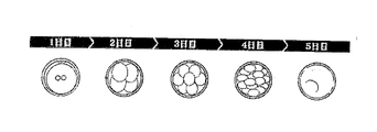
- the state in which the ovum has been fertilized is called a fertilized egg.
- This fertilized egg becomes a 4-cell embryo after 2 days from the division, and the division further proceeds and is transferred to the uterus. And, preserving these embryos ready for transplantation is becoming the mainstream of current infertility treatment.
- sperm is injected into a sperm storage container such as a specimen tube or a straw, and the egg or fertilized egg is a cryotop having a seat part (registered trademark of Kitasato Supply Co., Ltd.) or a cryo part having a loop part. It is held in an egg storage container such as a loop. Then, hold a plurality of sperm storage containers and egg storage containers in the cane, hold a plurality of canes holding the sperm storage containers etc. in the canister, and store and store the plurality of canisters in a cryopreservation tank. (See Patent Document 1 or 2).
- the cryopreservation tank is filled with liquid nitrogen, and the object is cryopreserved at an extremely low temperature of ⁇ 196 ° C. in a liquid phase or gas phase atmosphere.
- information data such as specimen number, patient name, collection date and time is manually written on one end of a sperm storage container, egg storage container, cane, etc.
- the embryo cultivator who handles the fertilized egg, etc. should confirm the written location or label of the container or instrument visually. I was doing.
- a label printed with a barcode is affixed to a sperm storage container, an egg storage container, a cane, etc., and an embryo culturer reads the barcode with a barcode reader, so that any patient's sperm, ovum, fertilized egg It was also done to identify.
- a plurality of sperm storage containers, egg storage containers, canes and the like are stored in a canister, and the plurality of canisters are stored in a cryopreservation tank filled with liquid nitrogen and stored in an environment of -196 ° C.
- frost or the like adheres to the container, instrument, or label, and the specimen number of the container, instrument, or label cannot be confirmed unless it is stripped or melted. It took a long time for the embryo cultivator to check, which reduced work efficiency and caused errors due to human error.
- an embryo incubator has previously performed operations such as egg, sperm collection, processing, fertilization, culture, cryopreservation, thawing, and transplantation, it is recorded on a recording sheet or a personal computer recording screen.
- operations such as egg, sperm collection, processing, fertilization, culture, cryopreservation, thawing, and transplantation
- the status of the treatment is not clearly shown in a timely manner to the patient to be treated, the patient has no way of knowing the progress of the treatment except at the timing of the examination.
- the present invention has been made to solve such a problem, and prevents the occurrence of a situation in which the sperm, ovum, fertilized egg, etc. to be treated are mistaken, and greatly improves the work efficiency of the embryo cultivator. Improve traceability (history traceability) that improves the performance, suppresses the decrease in fertilization rate and implantation rate, and records all work in the treatment including the work object, work content, worker, and work date and time. Furthermore, an object of the present invention is to provide an individual management system suitable for individual management of germ cells such as sperm, ovum, and fertilized egg that can be cryopreserved so that the patient can easily know the progress of treatment. .
- an object of the present invention is also to provide an individual management system suitable for individual management of germ cells such as animal sperm, ovum and fertilized egg.
- an individual management system of the present invention includes a server installed at an appropriate place in a facility, a plurality of personal computers, an identification code reader used at an appropriate place in the facility, an identification code, It is composed of an IC tag reader, an apparatus, an instrument, an instrument, and a container used for cryopreserving an object as appropriate, and at least an identification code attached to the apparatus, the instrument, the instrument, the container, and an attached IC tag. It is characterized by that.
- a label printer is installed at an appropriate place in the facility, and apparatuses, devices, instruments, and containers that are installed or used in the facility are connected by a network in the facility.
- the in-facility network is connected to a cloud server via the Internet so that a person using the facility can access the cloud server by a portable information terminal device.
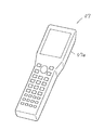
- the portable information terminal device is, for example, a mobile phone, a smartphone, or a tablet computer. According to this, a person using the facility can access the cloud server at an appropriate time and place.
- the facility is a facility for performing infertility treatment, particularly in vitro fertilization treatment. Alternatively, it may be a facility that stores and manages germ cells of animals.
- the apparatus / apparatus, instrument, and container for appropriately cryopreserving an object in liquid nitrogen include at least a cryopreservation tank, a canister, a cane, and an egg storage container.
- the cane is characterized in that an IC tag for cane can be freely attached to the grip portion.
- the cane IC tag preferably has a latch structure, and when the cane is inserted into the grip portion of the cane, the latch portion is bitten and cannot be easily detached from the cane grip portion.
- the cane IC tag may have a colored surface, or may have an ID printed on the surface or a label with an ID printed thereon.
- the egg storage container is characterized in that an IC tag for an egg storage container in which an inlet is stored in a coated pipe is attached to the upper end of the bowl-shaped portion.
- the inner diameter of the intermediate portion of the coated pipe is preferably smaller than the circumscribed circle diameter of the bowl-shaped portion of the egg storage container.
- the inlet is preferably formed with a hole or a groove in the axial direction.
- the inlet stores individual identification information of a fertilized egg and information related to the fertilized egg, or an ID associated with the information. Furthermore, it is preferable to store the container type code and the color code.
- the egg tag for the egg storage container may have a colored surface or a colored inlet. It is preferable that the egg storage container has an ID printed on its surface or a label on which an ID is printed. Moreover, it is preferable that the said IC tag for egg storage containers is what attached ID the label which printed ID on the surface, or printed ID.
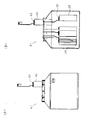
- the canister is characterized in that an IC tag for canister is suspended from its hooking portion.
- the device, apparatus, instrument, and container further include a sperm storage container.
- the sperm storage container is a sample tube, and the sample tube has a sample tube IC tag attached to a leg portion of the main body thereof.
- the sperm storage container is a sperm storage straw, and the sperm storage straw has a sperm storage straw IC tag mounted in a thin-walled pipe.
- the identification code / IC tag reader can be provided with an extension antenna via a connection cable so as to be convenient for reading the IC tag.
- the extension antenna may be composed of a holding member that holds the IC tag, an antenna element that is fitted to the holding member, and a connection cable that can be connected to the identification code / IC tag reader.
- the antenna element may have a cylindrical curved surface shape.
- the extension antenna may be composed of an antenna element wound with a coil and a connection cable that can be connected to the identification code / IC tag reader.
- the embryo cultivator reads the ID or information by the identification code / IC tag reader, not by visual observation.
- the situation which mixes up the sperm or ovum to be treated by mistake etc. does not occur.
- the sperm storage container, egg storage container, cane, etc. it takes almost no time for the sperm storage container, egg storage container, cane, etc. to be taken out of the cryopreservation tank and the embryo cultivator confirms the ID of the target object. After all, fertilization rate and implantation rate can be greatly improved. Further, since the IC tag to be used can operate even in an environment of ⁇ 196 ° C., data can be read while the object is inserted into the cryopreservation tank.
- the same effect can be exhibited even when animal sperm, ovum, fertilized egg and the like are cryopreserved.
- FIG. 1 It is a schematic block diagram of the individual management system of this invention. It is a network diagram of the individual management system of the present invention.
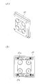
- (A) of a dish is a perspective view
- (B) is a top view. It is explanatory drawing which shows the culture
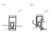
- (A) is a front view
- (B) is a sectional view showing a state in which sperm, eggs, fertilized eggs, etc. are cryopreserved in a cryopreservation tank filled with liquid nitrogen.
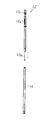
- It is a front view of a canister. It is a front view of a cane and an egg storage container. It is a perspective view of one Embodiment of an egg storage container.
- FIG. 1 It is a perspective view of an egg storage container and a protective sleeve.
- A of the inlet mounting part in the IC tag for egg storage containers is a front view
- B is sectional drawing. It is a front view which shows the state which printed ID on the bowl-shaped part of the egg storage container. It is a perspective view which shows the state which stuck the label which printed ID on the bowl-shaped part of the egg storage container. It is a front view which shows the state which printed ID on the covering pipe of the IC tag for egg storage containers. It is a front view which shows the state which stuck the label which printed ID on the coating pipe of the IC tag for egg storage containers. It is a front view of other embodiment of an egg storage container.
- molds the thin pipe which comprises the IC tag shown in FIG. 15 is the front view of the isolate
- (B) is a longitudinal cross-sectional view of the connected state. It is explanatory drawing which shows the method of shape
- FIG. 27 It is a perspective view which shows the state which affixed the label which printed ID on the surface part of the IC tag for cane. It is sectional drawing of a sample container. It is a perspective view which shows the state which hold
- FIG. 27A It is a schematic block diagram of the extension antenna attached to the identification code / IC tag reader shown in FIG. 27A is a front view and FIG. 28B is a perspective view of another embodiment of the extension antenna attached to the identification code / IC tag reader shown in FIG. 27A is a front view and FIG. 28B is a perspective view of another embodiment of the extension antenna attached to the identification code / IC tag reader shown in FIG.
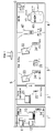
- the individual management system of the present invention includes a server 11, a printer 12, a personal computer 13 installed in the office 1, an identification code reader 14 used in the office 1, and an examination room 2.
- a personal computer 21 installed in the inside, an identification code reader 22 used in the examination room 2, a label printer 31 installed in the inspection / processing room 3, a tablet computer 33 used in the inspection / processing room 3,
- An identification code reader 34 a cryopreservation tank 41 disposed in the storage room 4, a canister 42, a cane 43, an egg storage container 44, etc., equipment, instruments, containers, etc. stored in the cryopreservation tank 41;
- an identification code / IC tag reader 47 used in the storage chamber 4.
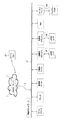
- the system can be operated by connecting to the cloud server 71 installed in the cloud provider 7 via the Internet 6.
- a patient undergoing in vitro fertilization can browse predetermined information from the cloud server 71 by a portable information terminal device 81 such as a mobile phone, a smartphone, or a tablet computer used by the patient under predetermined conditions. ing.
- the clerk inputs the patient number (ID), patient name, etc. to the personal computer 13, displays the patient information on the display, and performs a predetermined operation to collect the eggs.
- An instruction is created, and the egg collection instruction is printed by the printer 12.
- the egg collection instruction sheet is printed with a patient number (ID), a patient name, an instruction sheet number, and the like, and a two-dimensional code associated with the information.
- the person in charge arranges the containers used for the treatment in advance, and at the same time, the label printer 31 prints the patient number (ID) and the patient name on the label.
- a two-dimensional code having information on patient number (ID), patient name, instruction number, and container number (ID) is printed.
- This label is a label for adhering to a container, is printed in advance for the number of containers to be used, and is adhered to the container.
- a label to be attached to a wristband wound around the patient's wrist is also printed and attached to an appropriate portion of the wristband. On the day of egg collection, the wristband is attached to the patient after confirming the identity.
- a nurse or the like reads the instruction sheet, the label of the egg-collecting container that has been previously labeled, and the two-dimensional code of the patient's wristband with the identification code reader 22, and confirms that there is no mistake. .
- a doctor or the like collects a follicle from a patient and inserts the follicle into the egg collection container confirmed as described above. Immediately thereafter, the nurse or the like hands over the egg-collecting container into which the follicle is inserted and the instruction manual to the embryo culture technician.
- the embryo cultivator takes out the follicle from the received egg collection container and confirms the number of eggs.
- the instruction code and the two-dimensional code printed on the label affixed to the egg collection container are read by the identification code reader 34 to confirm the patient and the egg collection container, and then the number of eggs is determined by the tablet computer 33. Enter and record.
- the identification code reader 34 to confirm the patient and the egg collection container
- the number of eggs is determined by the tablet computer 33. Enter and record.
- the tablet computer 33 When moving the eggs whose number has been confirmed to another container, read the two-dimensional code of the original container and the two-dimensional code of the destination container, and input the number of eggs to be moved to the tablet computer 33. Record moving work.
- the doctors can check the number and state of the eggs. Can be confirmed.
- the embryo cultivator performs various processes on the ovum in the examination / processing chamber 3, puts the processed ovum in a storage container, and stores it in the incubator. Also in these operations, the storage location of the egg can be recorded and managed by reading the two-dimensional code of the storage container.
- IVF in vitro fertilization
- ICSI microinsemination
- the fertilized egg is cultured in the culture medium in the dish 32 in the incubator as shown in FIG. 3, the cell division into 4 or 8 after 2 to 3 days, as shown in FIG. become an embryo. If the culture is further continued, it will develop into a blastocyst in which the presence of the inner cell mass is observed after 5 to 6 days. After fertilization, the egg ID and the two-dimensional code of the container are linked to each individual unit to manage the individual fertilized eggs.
- the embryo cultivator reads the two-dimensional code printed on the label 32 a attached to the dish 32 by the identification code reader 34, specifies the target fertilized egg, and uses the tablet computer 33 to identify the fertilized egg. Record the culture status of.
- information related to the culture state of the fertilized egg is transferred and stored in the server 11 via the in-facility network 5. Therefore, by accessing the server 11, the information can be browsed from the personal computer 21 installed in the examination room 2 and the personal computer 13 installed in the office 1.
- blastocyst transplantation is performed in which the blastocyst in which the presence of the inner cell mass is observed after 5 to 6 days of culture is returned to the mother body.
- doctors and the like read the two-dimensional code printed on the label 32 a attached to the dish 32 by the identification code reader 22 and specify the target fertilized egg, and then transfer the transplant information to the personal computer 21. Enter.
- transplant information of the fertilized egg is transferred to the server 11 from the personal computer 21 installed in the examination room 2 via the in-facility network 5 and stored.
- the fertilized egg in a state in which transplantation can be performed is cryopreserved.
- the number of eggs that can be in vitro fertilized multiple times by one egg collection is collected.
- the maternal state has returned to its original state.
- cryopreservation tank 41 As shown in FIG. 5 to FIG. 8, the cryopreservation tank 41, the canister 42, the cane 43, the specimen tube 44, the egg storage container 45, and the protective sleeve 46 are used in the cryopreservation. Etc.
- the cryopreservation tank 41 includes a main body, an outer lid, and an inner lid, and the cryopreservation tank 41 is filled with liquid nitrogen LN at ⁇ 196 ° C.
- liquid nitrogen LN liquid nitrogen
- about 6 to 12 canisters 42 are radially suspended and held in the cryopreservation tank 41, and about 10 to 20 canes 43 are held in one canister 42.
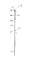
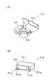
- the canister 42 includes a cylindrical portion 42a, a bowl-shaped portion 42b, a latching portion 42c, and a canister IC tag 42d.
- a plurality of canes 43 can be inserted into the cylindrical portion 42 a, and the latching portion 42 c can be hooked on the inner lid of the cryopreservation tank 41 and held in the cryopreservation tank 41.
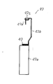
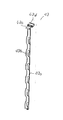
- the cane 43 includes a bowl-shaped portion 43 a, a holding portion 43 b, a gripping portion 43 c, and a cane IC tag 43 d.
- a specimen tube 44 that can store a plurality of egg storage containers 45 can be fitted and held in the holding portion 43b, and the egg storage container 45 can be held in the liquid nitrogen LN.
- the can IC tag 43d has an insertion structure as shown in FIG. 20A. As shown in FIG. 22A, the tag case 431 and the fitting hole 431a of the tag case 431 are provided. The flex IC tag 432 is attached to the tag case 431, and the label 433 is wound around the tag case 431.
- the tag case 431 has an insertion groove 431b, and engaging claws 431c and 431c are formed on both sides of the insertion groove 431b. And what is called a latch structure is comprised by the insertion groove part 431b and the engaging claw parts 431c and 431c.
- the cane IC tag 43d can be attached to the grip 43c as shown in FIG. it can.
- the grip portion 43c of the cane 43 is inserted into the insertion groove 431b of the cane IC tag 43d, the engaging claw portions 431c and 431c bite, and the cane IC tag 43d easily falls off from the grip portion 43c. There is nothing.
- the exterior material of the IC tag 43d is colored in a predetermined manner so that the cane 43 can be identified.
- color classification in addition to color classification by a single color, color classification may be performed using a plurality of colors. Further, a color pattern may be formed and identified.
- the ID is directly printed on the surface of the exterior material of the IC tag 43d for cane, or as shown in FIG. In this manner, a label printed with an ID may be attached to the surface of the exterior material so as to be identified.
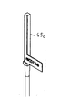
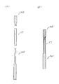
- the egg storage container 45 for storing an egg or a fertilized egg is composed of a square columnar bowl-shaped portion 45a and a synthetic resin holding plate 45b.
- a fertilized egg is placed on the tip of the holding plate 45b together with a small amount of storage solution, and after rapid freezing in liquid nitrogen, the egg storage container 45 is housed in a protective sleeve 46 as shown in FIG.
- This preservation method is called vitrification method, and it is cryopreserved without damaging the cells by vitrifying the whole preservation solution (a phenomenon that does not form ice crystals and becomes an amorphous glassy solid). Therefore, it has become the mainstream method for cryopreservation of fertilized eggs.
- An egg storage container IC tag 45c is attached to the upper end of the bowl-shaped portion 45a of the egg storage container 45 as shown in FIG.
- the egg tag 45c for an egg storage container is configured such that a cylindrical inlet 51 having a minute diameter is accommodated in a synthetic resin-coated pipe 52. Then, by filling the coated pipe 52 with resin or filler, the egg storage container IC tag 45c is fixed and attached to the upper end of the bowl-shaped portion 45a.
- the egg storage container 45 When the egg storage container 45 is inserted into the cryopreservation tank 41 and kept in a liquid nitrogen LN environment at -196 ° C, it is removed from the cryopreservation tank 41 and placed in a room temperature environment at 20 ° C. egg liquid nitrogen LN penetrated into the gap between the upper portion and egg storage container for IC tag 45c of rod-shaped portion 45a of the storage container 45 is vaporized, and nitrogen gas N 2 rapidly inflate the volume. As a result, an excessive pressure is applied to the egg storage container IC tag 45c, and the egg storage container IC tag 45c may jump out of the bowl-shaped portion 45a.
- a hole A or a groove B is formed in the inlet 51 of the egg storage container IC tag 45c in the axial direction. Therefore, even if the liquid nitrogen LN is vaporized and the volume is rapidly expanded to become the nitrogen gas N 2 , the nitrogen gas N 2 is discharged through the hole A or the groove B, so that the bowl-shaped portion There is no possibility that the egg storage container IC tag 45c jumps out of 45a.
- a hole C for venting gas may be formed on the peripheral side surface of the coated pipe 52 of the IC tag 45c for egg storage container, or an elongated slit may be formed in the axial direction. Even with such a configuration, the same operations and effects as described above can be achieved.
- the bowl-shaped portion 45a is colored in a predetermined manner so that the egg storage container 45 can be identified. Furthermore, if the covering pipe 52 or the inlet 51 of the IC tag 45c for egg storage container is given a predetermined color, a large number of objects can be visually identified by a combination with the coloring of the hook-like portion 45a.
- the ID is directly printed on the surface of the bowl-shaped portion 45a of the egg storage container 45, or the label printed with the ID is pasted on the surface of the bowl-shaped portion 45a as shown in FIG. Then, it may be identified. Also, as shown in FIG. 13, an ID is directly printed on the surface of the coated pipe 52 of the egg storage container IC tag 45c, or a label printed with an ID is printed on the surface of the coated pipe 52 as shown in FIG. You may make it stick and identify. According to this, even when the IC tag 45c breaks down and the ID cannot be read, or even when the IC tag 45c is detached, the object stored in the storage container can be read by visually reading the printed ID. It becomes possible to restore information on objects.
- another embodiment of the egg storage container IC tag 65 includes a synthetic resin thin pipe 66, an inlet 51 provided in the thin pipe 66, a fixing member 52 for fixing the inlet 51 from both sides, 52.
- the inner diameters of the opening 66a and the closing part 66c of the thin-walled pipe 66 are substantially the same as the circumscribed diameter of the bowl-shaped part 62 of the egg storage container 61, and the inner diameter of the intermediate part 66b is the bowl-shaped part. It is slightly smaller than 62 circumscribed circle diameter.
- the egg storage container IC tag 65 Since the egg storage container IC tag 65 has such a configuration, it is easy to insert the IC tag 65 into the bowl-shaped part 62 of the egg storage container 61, and further, by pushing into the bowl-shaped part 62, the intermediate The portion 66b can fasten the hook-shaped portion 62, and the IC tag 65 can be firmly fixed to the hook-shaped portion 2.
- Such a thin-walled pipe 66 can be formed using a forming jig 201 shown in FIG.
- a material having heat shrinkability is selected.
- the forming jig 201 is composed of a jig main body 202 and a jig head body 203, and a fitting hole portion of the jig head body 203 is formed in the tip protrusion 202 a of the jig main body 202. 203a is inserted and fitted.
- the outer diameter of the intermediate collar 202b of the jig body 202 is made slightly smaller than the outer diameter of the collar 62 of the egg storage container 61, and the outer diameter of the proximal collar 202c is made to be the flange 62 of the egg storage container 61. Is substantially the same as the outer diameter. Further, the outer diameter of the tip flange 203 b of the jig head 203 is substantially the same as the outer diameter of the flange 62 of the egg storage container 61.
- the material pipe 67 whose outer diameter before molding is substantially the same as the outer diameter of the bowl-shaped part 62 of the egg storage container 61 is extended to the proximal end collar part 202c of the jig body 202.
- the tip flange 203b of the jig head body 203 is inserted from one end opening of the material pipe 67, and the fitting hole 203a is fitted to the tip protrusion 202a. .
- the intermediate portion 67a of the material pipe 67 contracts and is shaped so as to follow the shape of the forming jig 201 as shown in FIG. .
- the jig body 202 and the jig head body 203 are separated, as shown in FIG.
- a thin pipe 66 having a small diameter at the intermediate portion 66b can be formed.
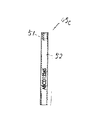
- specimen tubes, sperm storage straws, and the like are known as sperm storage containers used for cryopreserving sperm.
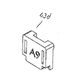
- the conventional sample tube 71 includes a tube main body 72 and a cap 73 that is screwed to the tube main body 72.
- the sample tube 76 of the present invention is configured by mounting a sample tube IC tag 74 on a leg portion 72a of a tube main body 72.
- the IC tag 74 can be attached to the cap 73.
- the plurality of sample tubes 76, 76,... With the sample tube IC tag 74 attached thereto are fitted into the cane 43 and stored.
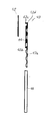
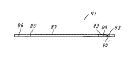
- a conventional sperm storage straw 81 includes a synthetic resin thin-walled pipe 82, cotton plugs 83, 83 loaded at one end of the thin-walled pipe 82, and the cotton plugs 83, 83. And a water absorbing body 84 loaded therebetween. Then, sperm is injected from the A end while sucking air from the B end of the thin-walled pipe 82, and the injection is stopped when the liquid level reaches the line 85. Thereafter, the other end portion of the thin pipe 82 is subjected to thermocompression bonding or ultrasonic pressure bonding, thereby forming a sealing portion 86 and sealing the thin pipe 82.
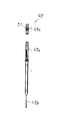
- the sperm storage straw 91 of the present invention includes an IC tag 92 contained in an outer cotton plug 83 which is a component of the sperm storage straw 81.
- the IC tag 92 is held so as not to inhibit air flow.
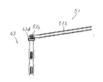
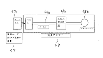
- the embryo cultivator carries an identification code / IC tag reader 47 as shown in FIG.
- the antenna unit 47a of the identification code / IC tag reader 47 is provided.
- a linking ID for retrieving information stored in the database is recorded.
- a label printed with a two-dimensional code is affixed to other containers used for work.
- the movement of the storage location of the egg egg ID
- the cane IC tag 43d attached to the cane 43 has a relatively large outer diameter, and therefore can be easily read by bringing the identification code / IC tag reader 47 close to the cane IC tag 43d. Since the egg storage container IC tag 45c attached to the container has a very small outer diameter, it may not be read even if the identification code / IC tag reader 47 is brought into contact therewith.
- the antenna part 47a of the identification code / IC tag reader 47 is arranged on the front side or the rear side of the identification code / IC tag reader 47, so that the IC tag 43d for cane matches the position of the antenna part 47a. It takes a long time to read.
- the extension antenna 48 can be attached to the identification code / IC tag reader 47.
- the extended antenna 48 includes a holding member 48a, an antenna element 48b, a connection cable 48c, and a clamping member 48d.
- the holding member 48a forms a fitting groove for fitting and holding the egg storage container IC tag 45c of the egg storage container 45 at the tip, and the tip of a holding tool such as tweezers 49 is fitted at the rear end.
- a holding tool such as tweezers 49
- an insertion hole for insertion is formed.
- the antenna element 48b is fitted inside the distal end portion of the holding member 48a, and a connection cable 48c is extended from one end portion thereof.
- the clamping member 48d has a fitting hole at the rear end thereof for fitting and inserting the tip of a holding tool such as tweezers 49.
- both ends of tweezers 49 are fitted into the fitting hole of the holding member 48a and the fitting hole of the holding member 48d, and the egg storage container 45 is stored in the fitting groove of the holding member 48a.
- the container IC tag 45c is fitted. If the tip of the tweezers 49 is closed and the egg storage container IC tag 45c is held between the holding member 48a and the holding member 48d, the antenna element 48b can receive electromagnetic energy from the IC tag 45c. The electromagnetic energy passes through the resonance / matching circuit 48e shown in FIG. 30 and then is transmitted to the antenna portion 47a of the identification code / IC tag reader 47 via the connection cable 48c. 47, the information data stored in the IC tag 45c can be read.
- an antenna element 101 curved in a thin cylindrical curved surface as shown in FIG. 31 may be employed.
- the antenna element 101 is obtained by adhering a coil winding to a thin cylindrical curved plate 102, and includes longitudinal elements 103 and 104 and lateral elements 105 and 106.
- magnetic fluxes 103A and 104A extend from the longitudinal elements 103 and 104, and magnetic flux 106A extends from the lateral element 106. Therefore, the inlet antenna located inside the antenna element 101 has magnetic fluxes from various directions. Will be crossed. Therefore, the reading performance does not deteriorate regardless of the direction of the antenna of the inlet of the IC tag 45c.
- the extension antenna 51 as shown in FIG. 29 may be attached to the identification code / IC tag reader 47.
- the extension antenna 51 is composed of an antenna element 51a and a connection cable 51b.
- the connection cable 51b is electromagnetically coupled to the antenna portion 47a of the identification code / IC tag reader 47 after passing through the resonance / matching circuit 48e shown in FIG.
- the tip of the extension antenna 51 can be placed in liquid nitrogen, so that the cane 43 held in the cryopreservation tank 41 can be used to hold the cane 43 from the liquid nitrogen.
- the IC tag 43d for cane can be read without taking it out.
- the information stored in the egg storage container IC tag 45c and the cane IC tag 43d read by the extension antennas 48 and 51 is installed in the office 1 via the in-facility network 5. It is transferred to the server 11 and stored.
- the clerk in charge, the doctor, the embryo cultivator, etc. can appropriately receive patient information and egg information. , Save information can be confirmed.
- the server 11 since the server 11 is connected to the in-facility network 5 and is also connected to the cloud server 71 via the Internet 6, the patient uses his / her own portable information terminal device 81, By accessing the cloud server 71, self-treatment information can be acquired.
- an SSL / TLS protocol such as HTTPS is preferably used to execute processing such as authentication for the cloud server 71, encryption of communication contents, and falsification detection.
- processing such as authentication for the cloud server 71, encryption of communication contents, and falsification detection.
- a general encryption process should be performed and measures should be taken so that information is not leaked to others.
- the individual management system of the present invention is equipped with an IC tag storing ID, specimen number, patient name, collection date and time in a sperm storage container, an egg storage container, a cane, etc. Since the embryo cultivator reads the information using an identification code / IC tag reader, the specimen number is wrongly set due to human error or memory mistake. There will be no mistakes.
- the information can be read by the identification code / IC tag reader even if the surface is covered with frost, etc.
- the ID, specimen number, and the like can be confirmed without removing the symbol, and the work efficiency of the embryo cultivator can be greatly improved.
- the work of carefully attaching the label to a narrow attaching portion is unnecessary.
- an embryo culturer when an embryo culturer performs operations such as egg, sperm collection, processing, fertilization, culture, storage, and transplantation, information is input to a recording screen of a personal computer. Therefore, the patient can appropriately check the information using a mobile phone or the like, which leads to an increase in treatment reliability.
- the individual management system of the present invention has been described for a case where it is applied to a facility that performs in vitro fertilization.
- the present invention is not limited to human beings, and cryopreservation and in vitro fertilization of sperm and eggs related to animals such as cows and horses. This can also be applied to cases where
Landscapes
- Engineering & Computer Science (AREA)
- Health & Medical Sciences (AREA)
- Life Sciences & Earth Sciences (AREA)
- General Health & Medical Sciences (AREA)
- Chemical & Material Sciences (AREA)
- Wood Science & Technology (AREA)
- Zoology (AREA)
- Physics & Mathematics (AREA)
- Bioinformatics & Cheminformatics (AREA)
- Organic Chemistry (AREA)
- Theoretical Computer Science (AREA)
- General Physics & Mathematics (AREA)
- Biomedical Technology (AREA)
- Veterinary Medicine (AREA)
- Public Health (AREA)
- Biotechnology (AREA)
- Computer Hardware Design (AREA)
- General Engineering & Computer Science (AREA)
- Biochemistry (AREA)
- Microbiology (AREA)
- Genetics & Genomics (AREA)
- Sustainable Development (AREA)
- Animal Behavior & Ethology (AREA)
- Business, Economics & Management (AREA)
- Dentistry (AREA)
- Environmental Sciences (AREA)
- Analytical Chemistry (AREA)
- Microelectronics & Electronic Packaging (AREA)
- Computer Vision & Pattern Recognition (AREA)
- Artificial Intelligence (AREA)
- Reproductive Health (AREA)
- Medical Informatics (AREA)
- Toxicology (AREA)
- Medicinal Chemistry (AREA)
- Clinical Laboratory Science (AREA)
- Surgery (AREA)
- Pharmacology & Pharmacy (AREA)
- Epidemiology (AREA)
- Electromagnetism (AREA)
- Primary Health Care (AREA)
Abstract
Description
卵子が受精した状態を受精卵と呼ぶが、この受精卵は、分割して2日後には4細胞期胚となり、さらに分割が進み、子宮に移植されることになる。
そして、これら移植の準備が整った状態の胚を凍結保存しておくのが、現在の不妊治療
の主流となりつつある。
そして、精子保存容器、卵子保存容器をケーンに複数個保持し、それら精子保存容器等を保持した複数のケーンをキャニスタに保持させ、それら複数のキャニスタを凍結保存用タンク内に収納して保存している(特許文献1又は2を参照)。
ここで、凍結保存用タンク内には液体窒素を充填し、液相又は気相の雰囲気において対象物を-196℃の極低温下で凍結保存している。
よって、本発明は、動物の精子、卵子、受精卵等の生殖細胞を個体管理するのに好適な個体管理システムを提供することをも目的とする。
ここで、前記施設内の適宜場所にラベルプリンタを設置し、前記施設内に設置又は使用
する装置、機器、器具、容器は、施設内ネットワークで接続したことを特徴とする。
携帯情報端末装置は、例えば、携帯用電話機、スマートフォン又はタブレットコンピュータであって、これによれば、適宜時間及び場所において、前記施設を利用する者は、前記クラウドサーバにアクセスすることができる。
そして、適宜対象物を液体窒素内で凍結保存する前記装置・機器、器具、容器は、少なくとも、凍結保存用タンクと、キャニスタと、ケーンと、卵子保存容器と、を含むことを特徴する。
前記ケーン用ICタグは、ラッチ構造を有し、前記ケーンの把持部に差し込むと、そのラッチ部が噛み込み、ケーンの把持部から容易に外れないものであることが好ましい。
ここで、被覆パイプは、その中間部の内径を前記卵子保存容器の杆状部の外接円直径よりも小としてあるのが好ましい。
又、インレットには、軸方向に孔部又は溝部を形成してあるのが好ましい。
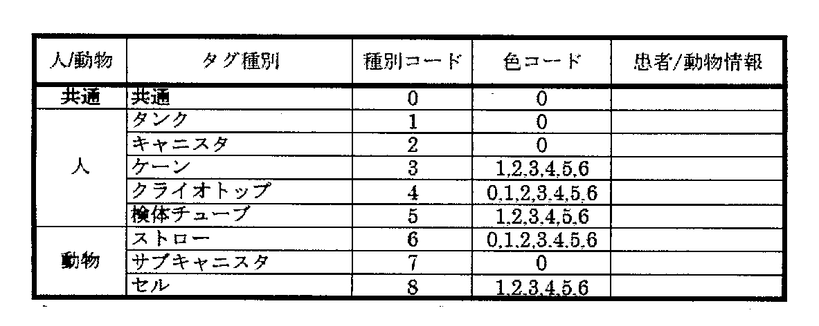
さらに、容器の種別コード及び色コードを記憶させるのが好ましい。
前記卵子保存容器は、その表面にIDを印字、又は、IDを印刷したラベルを貼着したものであることが好ましい。
又、前記卵子保存容器用ICタグは、その表面にIDを印字、又は、IDを印刷したラベルを貼着したものであることが好ましい。
前記延長アンテナは、ICタグを保持する保持部材と、この保持部材に嵌着したアンテナエレメントと、識別コード・ICタグ読取装置に接続できる接続ケーブルと、から構成されるものであってもよい。
ここで、アンテナエレメントは、円柱曲面形状を呈するものであってもよい。
又、使用するICタグは、-196℃の環境下においても動作可能であるので、対象物を凍結保存用タンクに挿入した状態のままで、データを読み取ることもできる。
さらに、インターネット6を介してクラウドプロバイダ7に設置されたクラウドサーバ71に接続して、システムを運用できるようになっている。
この場合、体外受精を受ける患者は、所定の条件下で、自身が使用する携帯用電話機、スマートフォン、タブレットコンピュータ等の携帯情報端末装置81によって、クラウドサーバ71から所定の情報を閲覧できるようになっている。
そこで、ICタグを装着する装置、機器、器具、容器の種別、ICタグの表面等に着色する色彩等の属性を含む情報をICタグ内に記憶させておくようにする。このような属性情報を個体管理システムにおいて種々作業をする際に利用することによって、システムの効率と使い勝手を大幅に向上させることができる。
ICタグ内に記憶させる属性情報の具体例を表1及び2に示す。

個体管理システムが電子カルテシステムと連携している場合には、パーソナルコンピュータ13に患者番号(ID)を入力することによって、必要な患者情報を電子カルテシステムから受信することができる。
尚、採卵指示書には、患者番号(ID)、患者氏名、指示書番号等が印字されていると共に、これら情報に紐付けた2次元コードが印刷されている。
このラベルは、容器に貼着するためのラベルであって、使用する容器の数だけ事前に印刷し、容器に貼着する。
又、患者の手首に巻き付けるリストバンドに貼着するラベルをも印刷し、リストバンドの適宜個所に貼着する。そして、採卵を行う当日は、本人であることを確認の上、患者にリストバンドを装着させる。
そして、指示書、採卵容器に貼着されたラベルに印刷された2次元コードを識別コード読取装置34によって読み取って、患者と採卵容器とを確認した上で、タブレットコンピュータ33によって、卵子の個数を入力し、記録する。
尚、個数を確認した卵子を別の容器に移動する場合には、元の容器の2次元コードと移動先の容器の2次元コードとを読み、タブレットコンピュータ33に移動する卵子の個数を入力し、移動作業を記録する。
これらの情報は、施設内ネットワーク5を介して、事務室1内に設置したサーバ11に送信され、サーバ11内に記憶される。
これらの作業においても、保存容器の2次元コードを読み取ることによって、卵子の保存場所等の記録及び管理を行うことができる。
又、卵子の卵細胞質内にマイクロピペットによって精子を注入して受精させる顕微授精(ICSI)を実施する場合もある。
尚、受精後は、卵子IDと容器の2次元コードを個体単位で紐付け、受精卵の個体管理を行う。
従って、サーバ11にアクセスすることによって、診察室2に設置されたパーソナルコンピュータ21、事務室1に設置されたパーソナルコンピュータ13からその情報を閲覧することができる。
採卵による母体の負担を軽減するため、1回の採卵で複数回の体外受精を行えるだけの個数の卵子を採取するようにする。そして、胚移植複数回分の受精卵を凍結保存しておくことによって、排卵促進剤の影響等で採卵した周期の子宮環境が移植に適さない時に移植せず、母体の状態が元に戻った次周期以降に移植することによって、着床率を高め、妊娠率を高めるようにする。
凍結保存用タンク41内には6~12個程度のキャニスタ42が放射状に吊下、保持され、1個のキャニスタ42内には10~20個程度のケーン43が保持される。
円筒部42a内には複数個のケーン43を挿入でき、掛止部42cを凍結保存用タンク41の内蓋に掛止して、凍結保存用タンク41内に保持できるようになっている。
保持部43bには、複数本の卵子保存容器45を収納できる検体チューブ44を嵌着、保持できるようになっており、卵子保存容器45を液体窒素LN内に保持できるようになっている。
そして、挿入溝部431b及び係合爪部431c,431cによって、いわゆるラッチ構造を構成してある。
ここで、ケーン43の把持部43cをケーン用ICタグ43dの挿入溝部431bに一旦差し込むと、係合爪部431c,431cが噛み込むので、把持部43cからケーン用ICタグ43dが容易に脱落することはない。
尚、限られた色数しかなく、色が重複する場合を考慮して、図21に示すように、ケーン用ICタグ43dの外装材の表面にIDを直接印刷し、又は、図22に示すように、外装材の表面にIDを印刷したラベルを貼着して、識別するようにしてもよい。
保持板45bの先端部に少量の保存液と共に受精卵を載置させ、液体窒素中で急速凍結した後、図9に示すように、卵子保存容器45を保護用スリーブ46に収容する。
この保存方法は、ガラス化法と呼ばれており、保存液ごとガラス化(氷晶形成せず、無結晶のガラス状の固体となる現象)させることにより、細胞を傷付けることなく凍結保存することが可能なため、受精卵の凍結保存方法の主流となっている。
卵子保存容器用ICタグ45cは、図10に示すように、合成樹脂製の被覆パイプ52内に微小径である円筒状のインレット51を収納し、構成してある。
そして、被覆パイプ52内に樹脂又は充填剤を充填することによって、卵子保存容器用ICタグ45cを杆状部45aの上端部に固定、装着してある。
これによって、卵子保存容器用ICタグ45cに過大な圧力が負荷され、杆状部45aから卵子保存容器用ICタグ45cが飛び出す虞がある。
よって、液体窒素LNが気化し、急激に体積を膨張させて窒素ガスN2となっても、窒素ガスN2は、この孔部A又は溝部Bを通過して放出されるから、杆状部45aから卵子保存容器用ICタグ45cが飛び出す虞はない。
このような構成によっても、上記と同様の作用、効果を奏することができる。
さらに、卵子保存容器用ICタグ45cの被覆パイプ52又はインレット51に所定の着色をしておけば、杆状部45aの着色との組み合わせによって、多数の対象物を目視により識別することができる。
又、図13に示すように、卵子保存容器用ICタグ45cの被覆パイプ52の表面にIDを直接印刷し、又は、図14に示すように、被覆パイプ52の表面にIDを印刷したラベルを貼着して、識別するようにしてもよい。
これによれば、ICタグ45cが故障してIDが読めない場合や、ICタグ45cが外れてしまった場合でも、前記の印字されたIDを目視で読むことによって、保存容器に保存された対象物の情報を復元することが可能になる。
そして、図15に示すように、薄肉パイプ66の開口部66a及び閉鎖部66cの内径を卵子保存容器61の杆状部62の外接円直径と略同一とし、中間部66bの内径を杆状部62の外接円直径より若干小としてある。
成形治具201は、図16に示すように、治具本体202と治具頭体203とから構成されており、治具本体202の先端突部202aに治具頭体203の嵌合穴部203aを差し込み、嵌合するようになっている。
又、治具頭体203の先端杆部203bの外径を卵子保存容器61の杆状部62の外径と略同一としてある。
中間部66bが小径の薄肉パイプ66を成形することができる。
尚、キャップ73にICタグ74を装着することもできる。
そして、薄肉パイプ82のB端から空気を吸引しながらA端から精子を注入し、液面が85のラインに到達した時に注入を停止する。
その後、薄肉パイプ82の他端部を熱圧着又は超音波圧着することによって、封止部86を形成して、薄肉パイプ82を密閉する。
ICタグ92を包含させたことにより、通気を阻害しないようにICタグ92を保持している。
そして、受精卵の凍結保存を開始する際、保存状態を確認する際、融解作業を行う際、凍結保存を終了(廃棄)する際等において、識別コード・ICタグ読取装置47のアンテナ部47aをケーン43、卵子保存容器45に装着したケーン用ICタグ43d、卵子保存容器用ICタグ45cに近接させて、ケーン用ICタグ43d、卵子保存容器用ICタグ45c内に記憶させたID、患者情報、保存情報を読み取る。
ケーン用ICタグ43d、卵子保存容器用ICタグ45cには、データベースに格納した情報を取り出すための紐付けIDを記録しておく。又は、患者情報、卵子に関する情報、保存情報を記録しておいてもよい。
又、作業に使用するその他の容器には、2次元コードを印刷したラベルが貼られており、
収納されている卵子を移動する際に、それぞれの容器の2次元コードを読み取ることで、
卵子(卵子ID)の保存場所の移動を管理している。
又、識別コード・ICタグ読取装置47のアンテナ部47aは、識別コード・ICタグ読取装置47の前面側又は背面側に配置されているため、アンテナ部47aの位置にケーン用ICタグ43dを合致させるようにして読み取る必要があり、読み取り作業に時間がかかる。
延長アンテナ48は、図28に示すように、保持部材48aと、アンテナエレメント48bと、接続ケーブル48cと、挟持部材48dと、から構成してある。
アンテナエレメント48bは、保持部材48aの先端部の内側に嵌着してあり、その一端部から接続ケーブル48cを延出してある。
挟持部材48dは、その後端部にピンセット49等の保持用具の先端部を嵌合、挿入する嵌入孔を形成してある。
そして、ピンセット49の先端部を閉鎖させ、保持部材48aと挟持部材48dとによって卵子保存容器用ICタグ45cを挟持すれば、アンテナエレメント48bはICタグ45cから電磁エネルギを受信することができる。
その電磁エネルギは、図30に示す共振・整合回路48eを通った後、接続ケーブル48cを介して識別コード・ICタグ読取装置47のアンテナ部47aに伝送されるから、識別コード・ICタグ読取装置47によって、ICタグ45cに格納した情報データを読み取ることができる。
アンテナエレメント101は、薄肉円筒曲面板102にコイルの巻線を貼着したものであって、縦方向エレメント103,104及び横方向エレメント105,106を構成してある。
よって、ICタグ45cのインレットのアンテナの向きがどの方向であろうとも、読み取り性能が低下することはない。
よって、基板積層型のインレット111に対しても、十分な読み取り性能を確保することができる。
延長アンテナ51は、図29に示すように、アンテナエレメント51aと、接続ケーブル51bと、から構成してある。
ここで、接続ケーブル51bは、図30に示す共振・整合回路48eを通った後、識別コード・ICタグ読取装置47のアンテナ部47aに電磁的に結合される。
事務室に設置されたパーソナルコンピュータ13、診察室2に設置されたパーソナルコンピュータ21によって、サーバ11から情報を受け取ることによって、担当事務員、医師、胚培養士等は、適宜、患者情報、卵子情報、保存情報を確認することができる。
そこで、患者は、クラウドサーバ71にアクセスする権限の付与を個体管理システムの管理者に申請し、管理者は、厳格な審査を行った上で、当該患者にアクセスする権限を付与するべきである。又、患者がアクセスできる情報の種類について制限する必要もある。そして、当該患者に固有の識別番号、パスワードを入力しなければ、アクセスできないようにするべきである。
データ通信には、HTTPS等のSSL/TLSプロトコルを採用して、クラウドサーバ71に対する認証、通信内容の暗号化、改鼠検出等の処理を実行するのが好ましい。通信本文の内容についても、一般的な暗号化処理を実行し、情報が他者に漏れないような手段を講じるべきである。
又、バーコードを印刷したラベルを容器に貼り付けて管理を行う場合にも、狭い貼り付け個所に注意深くラベルを貼るという作業は不要になる。
11 サーバ
13 パーソナルコンピュータ
14 識別コード読取装置
2 診察室(処置室)
21 パーソナルコンピュータ
22 識別コード読取装置
3 検査・処理室
31 ラベルプリンタ
33 タブレットコンピュータ
34 識別コード読取装置
4 保管室
41 凍結保存用タンク
43 ケーン
43c 掛止部
43d ICタグ
45 卵子保存容器
45a 杆状部
45c ICタグ
47 識別コード・ICタグ読取装置
48 延長アンテナ
48a 保持部材
48b アンテナエレメント
48c 接続ケーブル
48d 挟持部材
51 延長アンテナ
51a アンテナエレメント
51b 接続ケーブル
5 施設内ネットワーク
6 インターネット
71 クラウドサーバ
81 携帯情報端末装置
Claims (30)
- 施設内の適宜場所に設置したサーバと、複数のパーソナルコンピュータと、施設内の適宜場所で使用する識別コード読取装置と、識別コード・ICタグ読取装置と、適宜対象物を凍結保存するために使用する装置、機器、器具、容器と、少なくとも前記装置、機器、器具、容器に付着した識別コード及び装着したICタグと、から構成されることを特徴とする個体管理システム。
- 前記施設内の適宜場所にラベルプリンタを設置したことを特徴とする請求項1に記載の個体管理システム。
- 前記施設内に設置又は使用する装置、機器、器具、容器を施設内ネットワークで接続したことを特徴とする請求項1又は2に記載の個体管理システム。
- さらに、前記施設内ネットワークを、インターネットを介してクラウドサーバに接続したことを特徴とする請求項3に記載の個体管理システム。
- 前記施設を利用する者は、携帯情報端末装置によって前記クラウドサーバにアクセスできることを特徴とする請求項4に記載の個体管理システム。
- 前記携帯情報端末装置は、携帯用電話機、スマートフォン又はタブレットコンピュータであることを特徴とする請求項5に記載の個体管理システム。
- 前記施設は、体外受精を実施する施設であることを特徴とする請求項1乃至6の何れか1に記載の個体管理システム。
- 前記施設は、動物の生殖細胞の保存と管理を行う施設であることを特徴とする請求項1乃至6の何れか1に記載の個体管理システム。
- 適宜対象物を液体窒素内で凍結保存する前記装置、機器、器具、容器は、少なくとも、凍結保存用タンクと、キャニスタと、ケーンと、卵子保存容器と、を含むことを特徴する請求項1乃至8の何れか1に記載の個体管理システム。
- 前記ケーンは、その把持部にケーン用ICタグを装着自在としたものであることを特徴とする請求項9に記載の個体管理システム。
- 前記ケーン用ICタグは、ラッチ構造を有し、前記ケーンの把持部に差し込むと、そのラッチ部が噛み込み、ケーンの把持部から容易に外れないものであることを特徴とする請求項10に記載の個体管理システム。
- 前記ケーン用ICタグは、その表面を着色したものであることを特徴とする請求項10又は11に記載の個体管理システム。
- 前記ケーン用ICタグは、その表面にIDを印字、又は、IDを印刷したラベルを貼着したものであることを特徴とする請求項10乃至12の何れか1に記載の個体管理システム。
- 前記卵子保存容器は、その杆状部の上端部に、被覆パイプ内にインレットを収納した卵子保存容器用ICタグを装着したものであることを特徴とする請求項9に記載の個体管理システム。
- 前記被覆パイプは、その中間部の内径を前記卵子保存容器の杆状部の外接円直径よりも小としたことを特徴とする請求項14に記載の個体管理システム。
- 前記インレットには、軸方向に孔部又は溝部を形成してあることを特徴とする請求項14又は15に記載の個体管理システム。
- 前記インレットには、受精卵の個体識別情報及び受精卵に関する情報を記憶させることを特徴とする請求項14乃至16の何れか1に記載の個体管理システム。
- 前記インレットには、容器の種別コード及び色コードを記憶させることを特徴とする請求項14乃至17の何れか1に記載の個体管理システム。
- 前記卵子保存容器用ICタグは、その表面を着色したものであることを特徴とする請求項14乃至18の何れか1に記載の個体管理システム。
- 前記卵子保存容器用ICタグは、そのインレットを着色したものであることを特徴とする請求項14乃至19の何れか1に記載の個体管理システム。
- 前記卵子保存容器は、その表面にIDを印字、又は、IDを印刷したラベルを貼着したものであることを特徴とする請求項14乃至20の何れか1に記載の個体管理システム。
- 前記卵子保存容器用ICタグは、その表面にIDを印字、又は、IDを印刷したラベルを貼着したものであることを特徴とする請求項14乃至21の何れか1に記載の個体管理システム。
- 前記キャニスタは、その掛止部にキャニスタ用ICタグを吊下したものであることを特徴とする請求項9に記載の個体管理システム。
- 前記装置、機器、器具、容器は、さらに、精子保存容器を含むことを特徴する請求項9に記載の個体管理システム。
- 前記精子保存容器は、検体チューブであって、前記検体チューブは、その本体の脚部に検体チューブ用ICタグを装着したものであることを特徴とする請求項24に記載の個体管理システム。
- 前記精子保存容器は、精子保存用ストローであって、前記精子保存用ストローは、その薄肉パイプ内に精子保存用ストロー用ICタグを装着したものであることを特徴とする請求項24に記載の個体管理システム。
- 前記識別コード・ICタグ読取装置は、延長アンテナを付設できることを特徴とする請求項1乃至26の何れか1に記載の個体管理システム。
- 前記延長アンテナは、ICタグを保持する保持部材と、この保持部材に嵌着したアンテナエレメントと、前記識別コード・ICタグ読取装置に接続できる接続ケーブルと、から構成されることを特徴とする請求項27に記載の個体管理システム。
- 前記アンテナエレメントは、円柱曲面形状を呈するものであることを特徴とする請求項28に記載の個体管理システム。
- 前記延長アンテナは、コイルを巻回したアンテナエレメントと、前記識別コード・ICタグ読取装置に接続できる接続ケーブルと、から構成されることを特徴とする請求項27に記載の個体管理システム。
Priority Applications (6)
| Application Number | Priority Date | Filing Date | Title |
|---|---|---|---|
| AU2017327143A AU2017327143A1 (en) | 2016-09-13 | 2017-09-12 | Individual management system |
| CA3036772A CA3036772A1 (en) | 2016-09-13 | 2017-09-12 | Individual management system |
| CN201780069897.5A CN109952578A (zh) | 2016-09-13 | 2017-09-12 | 个体管理系统 |
| US16/332,715 US20200196595A1 (en) | 2016-09-13 | 2017-09-12 | Individual management system |
| EP17850895.8A EP3522076B1 (en) | 2016-09-13 | 2017-09-12 | Individual management system |
| KR1020197007275A KR20190053852A (ko) | 2016-09-13 | 2017-09-12 | 개체 관리 시스템 |
Applications Claiming Priority (2)
| Application Number | Priority Date | Filing Date | Title |
|---|---|---|---|
| JP2016179050A JP6954729B2 (ja) | 2016-09-13 | 2016-09-13 | 個体管理システム |
| JP2016-179050 | 2016-09-13 |
Publications (1)
| Publication Number | Publication Date |
|---|---|
| WO2018051994A1 true WO2018051994A1 (ja) | 2018-03-22 |
Family
ID=61619477
Family Applications (1)
| Application Number | Title | Priority Date | Filing Date |
|---|---|---|---|
| PCT/JP2017/032945 Ceased WO2018051994A1 (ja) | 2016-09-13 | 2017-09-12 | 個体管理システム |
Country Status (9)
| Country | Link |
|---|---|
| US (1) | US20200196595A1 (ja) |
| EP (1) | EP3522076B1 (ja) |
| JP (1) | JP6954729B2 (ja) |
| KR (1) | KR20190053852A (ja) |
| CN (1) | CN109952578A (ja) |
| AU (1) | AU2017327143A1 (ja) |
| CA (1) | CA3036772A1 (ja) |
| TW (1) | TWI756263B (ja) |
| WO (1) | WO2018051994A1 (ja) |
Cited By (3)
| Publication number | Priority date | Publication date | Assignee | Title |
|---|---|---|---|---|
| JP2021174399A (ja) * | 2020-04-28 | 2021-11-01 | 凸版印刷株式会社 | 管理システム、管理装置および管理方法 |
| JP2023510909A (ja) * | 2020-01-17 | 2023-03-15 | イングラン, エルエルシー | シリアル化人工授精ストロー並びに認証システム及び方法 |
| WO2025206104A1 (ja) * | 2024-03-27 | 2025-10-02 | 株式会社メデタ | 生殖医療支援サーバおよび支援方法 |
Families Citing this family (4)
| Publication number | Priority date | Publication date | Assignee | Title |
|---|---|---|---|---|
| JP6732874B2 (ja) * | 2018-12-28 | 2020-07-29 | 憲隆 福永 | 胚画像配信システムおよびその方法 |
| JP7148571B2 (ja) * | 2020-07-08 | 2022-10-05 | 憲隆 福永 | 胚画像配信システムおよびその方法 |
| KR102605018B1 (ko) * | 2021-08-25 | 2023-11-24 | 주식회사 페쿠스 | 가축 사양관리 시스템의 정액스트로 인식장치 |
| KR102579483B1 (ko) * | 2021-12-16 | 2023-09-19 | 서울대학교병원 | 검체 관리 시스템 |
Citations (6)
| Publication number | Priority date | Publication date | Assignee | Title |
|---|---|---|---|---|
| JP2006004299A (ja) * | 2004-06-18 | 2006-01-05 | Hitachi Medical Corp | 情報処理システム及び方法 |
| JP2007066011A (ja) * | 2005-08-31 | 2007-03-15 | Nippon Sheet Glass Co Ltd | 電子タグおよびこの電子タグを用いた電子タグ付き細径管 |
| WO2007077996A1 (ja) * | 2006-01-05 | 2007-07-12 | Hitachi Chemical Co., Ltd. | 個体識別が可能な管状容器 |
| JP2014212724A (ja) * | 2013-04-25 | 2014-11-17 | 実行データサイエンス株式会社 | 収容容器及びサンプル管理方法 |
| JP2015109507A (ja) * | 2013-12-03 | 2015-06-11 | 株式会社Iro | バルブ開閉用のソケット嵌合部、バルブ、バルブ開閉器、バルブ情報読取装置 |
| JP2015222539A (ja) * | 2014-05-23 | 2015-12-10 | 大日本印刷株式会社 | 細胞保管システム、細胞保管方法、及びプログラム |
Family Cites Families (12)
| Publication number | Priority date | Publication date | Assignee | Title |
|---|---|---|---|---|
| WO2006052803A2 (en) * | 2004-11-04 | 2006-05-18 | Precision Dynamics Corporation | Combined barcode scanner and radio frequency identification reader with field interpretation array |
| EP1812605A4 (en) * | 2004-11-05 | 2012-04-25 | Life Technologies Corp | COMPOSITIONS AND METHODS FOR USING HIGH FREQUENCY IDENTIFIERS FOR LIFE SCIENCES |
| TW200713080A (en) * | 2005-09-07 | 2007-04-01 | Zheng-Yang Li | Diagram representing method and structure for the examination result of human body system |
| US8872627B2 (en) * | 2010-02-12 | 2014-10-28 | Biotillion, Llc | Tracking biological and other samples using RFID tags |
| GB201304369D0 (en) * | 2013-03-08 | 2013-04-24 | Cryogatt Systems Ltd | Rfid caps and lids |
| EP2779020B1 (en) * | 2013-03-14 | 2015-10-28 | Intermec IP Corp. | Synthetic aperture RFID handheld with tag location capability |
| JP6243194B2 (ja) | 2013-11-05 | 2017-12-06 | 大陽日酸株式会社 | 凍結保存装置 |
| US10493457B2 (en) * | 2014-03-28 | 2019-12-03 | Brooks Automation, Inc. | Sample storage and retrieval system |
| JP2016067807A (ja) | 2014-10-01 | 2016-05-09 | 株式会社AnimoScience | ストロー管、並びに精液又は受精卵の凍結保存方法 |
| US20160353730A1 (en) * | 2015-06-02 | 2016-12-08 | Tokitae Llc | Containers for liquid nitrogen storage of semen straws |
| CN105160152A (zh) * | 2015-07-31 | 2015-12-16 | 广州优阳信息技术有限公司 | 一种人工授精、体外受精与胚胎移植的安全操作方法 |
| CN105761041A (zh) * | 2016-02-23 | 2016-07-13 | 苏州银橡智能科技有限公司 | 一种化学品智能管理方法及其管理系统 |
-
2016
- 2016-09-13 JP JP2016179050A patent/JP6954729B2/ja active Active
-
2017
- 2017-09-12 TW TW106131192A patent/TWI756263B/zh active
- 2017-09-12 WO PCT/JP2017/032945 patent/WO2018051994A1/ja not_active Ceased
- 2017-09-12 AU AU2017327143A patent/AU2017327143A1/en not_active Abandoned
- 2017-09-12 EP EP17850895.8A patent/EP3522076B1/en active Active
- 2017-09-12 CN CN201780069897.5A patent/CN109952578A/zh active Pending
- 2017-09-12 US US16/332,715 patent/US20200196595A1/en not_active Abandoned
- 2017-09-12 CA CA3036772A patent/CA3036772A1/en not_active Abandoned
- 2017-09-12 KR KR1020197007275A patent/KR20190053852A/ko not_active Withdrawn
Patent Citations (6)
| Publication number | Priority date | Publication date | Assignee | Title |
|---|---|---|---|---|
| JP2006004299A (ja) * | 2004-06-18 | 2006-01-05 | Hitachi Medical Corp | 情報処理システム及び方法 |
| JP2007066011A (ja) * | 2005-08-31 | 2007-03-15 | Nippon Sheet Glass Co Ltd | 電子タグおよびこの電子タグを用いた電子タグ付き細径管 |
| WO2007077996A1 (ja) * | 2006-01-05 | 2007-07-12 | Hitachi Chemical Co., Ltd. | 個体識別が可能な管状容器 |
| JP2014212724A (ja) * | 2013-04-25 | 2014-11-17 | 実行データサイエンス株式会社 | 収容容器及びサンプル管理方法 |
| JP2015109507A (ja) * | 2013-12-03 | 2015-06-11 | 株式会社Iro | バルブ開閉用のソケット嵌合部、バルブ、バルブ開閉器、バルブ情報読取装置 |
| JP2015222539A (ja) * | 2014-05-23 | 2015-12-10 | 大日本印刷株式会社 | 細胞保管システム、細胞保管方法、及びプログラム |
Non-Patent Citations (1)
| Title |
|---|
| See also references of EP3522076A4 * |
Cited By (5)
| Publication number | Priority date | Publication date | Assignee | Title |
|---|---|---|---|---|
| JP2023510909A (ja) * | 2020-01-17 | 2023-03-15 | イングラン, エルエルシー | シリアル化人工授精ストロー並びに認証システム及び方法 |
| JP7474856B2 (ja) | 2020-01-17 | 2024-04-25 | イングラン, エルエルシー | シリアル化人工授精ストロー並びに認証システム及び方法 |
| JP2021174399A (ja) * | 2020-04-28 | 2021-11-01 | 凸版印刷株式会社 | 管理システム、管理装置および管理方法 |
| JP7547771B2 (ja) | 2020-04-28 | 2024-09-10 | Toppanホールディングス株式会社 | 管理システム、管理装置および管理方法 |
| WO2025206104A1 (ja) * | 2024-03-27 | 2025-10-02 | 株式会社メデタ | 生殖医療支援サーバおよび支援方法 |
Also Published As
| Publication number | Publication date |
|---|---|
| TWI756263B (zh) | 2022-03-01 |
| CN109952578A (zh) | 2019-06-28 |
| EP3522076B1 (en) | 2023-08-02 |
| KR20190053852A (ko) | 2019-05-20 |
| CA3036772A1 (en) | 2018-03-22 |
| JP2018042693A (ja) | 2018-03-22 |
| TW201825056A (zh) | 2018-07-16 |
| EP3522076A1 (en) | 2019-08-07 |
| JP6954729B2 (ja) | 2021-10-27 |
| US20200196595A1 (en) | 2020-06-25 |
| AU2017327143A1 (en) | 2019-05-02 |
| EP3522076A4 (en) | 2020-08-12 |
Similar Documents
| Publication | Publication Date | Title |
|---|---|---|
| WO2018051994A1 (ja) | 個体管理システム | |
| JP6954728B2 (ja) | 凍結保存容器 | |
| Arav et al. | A new, simple, automatic vitrification device: preliminary results with murine and bovine oocytes and embryos | |
| US20180368394A1 (en) | Semen/gamete and embryo storage receptacles with rfid data identification | |
| CN114927178A (zh) | 患者和生物样本识别和追踪的方法和系统 | |
| US12354716B2 (en) | Handling and tracking of biological specimens for cryogenic storage | |
| Seidel et al. | Embryo transfer in dairy cattle | |
| Roy et al. | Chapter 20 gavi-automated vitrification instrument | |
| Tsang et al. | Cryopreservation of mammalian embryos: Advancement of putting life on hold | |
| US20170121736A9 (en) | Apparatus and method for processing microscopic single cell biological specimens with a single microtool | |
| CN204443898U (zh) | 新型胚胎玻璃化冷冻装载麦管 | |
| Guan et al. | Conservation of mouse models through embryo freezing | |
| Kohut et al. | A tissue perfusion harvest model for optimal multisystem comparisons of pathobiology | |
| Golubeva et al. | Collection and preparation of rodent embryonic samples for transcriptome study | |
| JP2023088806A (ja) | 凍結保存用具 | |
| JP2025067723A (ja) | 凍結保存容器および凍結保存システム | |
| Ivani | Setting Up a Cryopreservation Lab and Selecting Media, Disposables, and Systems for Vitrification | |
| Gosden | Techniques for slow cryopreservation of embryos | |
| Bedaiwy et al. | Appendix C: Ovarian Tissue Cryopreservation | |
| JP2007312745A (ja) | マイクロマニピュレーション方法 |
Legal Events
| Date | Code | Title | Description |
|---|---|---|---|
| 121 | Ep: the epo has been informed by wipo that ep was designated in this application |
Ref document number: 17850895 Country of ref document: EP Kind code of ref document: A1 |
|
| ENP | Entry into the national phase |
Ref document number: 20197007275 Country of ref document: KR Kind code of ref document: A |
|
| ENP | Entry into the national phase |
Ref document number: 3036772 Country of ref document: CA |
|
| NENP | Non-entry into the national phase |
Ref country code: DE |
|
| ENP | Entry into the national phase |
Ref document number: 2017850895 Country of ref document: EP Effective date: 20190415 |
|
| ENP | Entry into the national phase |
Ref document number: 2017327143 Country of ref document: AU Date of ref document: 20170912 Kind code of ref document: A |
|
| WWG | Wipo information: grant in national office |
Ref document number: 11201902224V Country of ref document: SG |
|
| WWP | Wipo information: published in national office |
Ref document number: 11201902224V Country of ref document: SG |