WO2018055905A1 - 撮像装置 - Google Patents
撮像装置 Download PDFInfo
- Publication number
- WO2018055905A1 WO2018055905A1 PCT/JP2017/027362 JP2017027362W WO2018055905A1 WO 2018055905 A1 WO2018055905 A1 WO 2018055905A1 JP 2017027362 W JP2017027362 W JP 2017027362W WO 2018055905 A1 WO2018055905 A1 WO 2018055905A1
- Authority
- WO
- WIPO (PCT)
- Prior art keywords
- supported
- imaging unit
- imaging
- bracket
- optical axis
- Prior art date
- Legal status (The legal status is an assumption and is not a legal conclusion. Google has not performed a legal analysis and makes no representation as to the accuracy of the status listed.)
- Ceased
Links
Images









Classifications
-
- B—PERFORMING OPERATIONS; TRANSPORTING
- B60—VEHICLES IN GENERAL
- B60R—VEHICLES, VEHICLE FITTINGS, OR VEHICLE PARTS, NOT OTHERWISE PROVIDED FOR
- B60R11/00—Arrangements for holding or mounting articles, not otherwise provided for
- B60R11/04—Mounting of cameras operative during drive; Arrangement of controls thereof relative to the vehicle
-
- G—PHYSICS
- G03—PHOTOGRAPHY; CINEMATOGRAPHY; ANALOGOUS TECHNIQUES USING WAVES OTHER THAN OPTICAL WAVES; ELECTROGRAPHY; HOLOGRAPHY
- G03B—APPARATUS OR ARRANGEMENTS FOR TAKING PHOTOGRAPHS OR FOR PROJECTING OR VIEWING THEM; APPARATUS OR ARRANGEMENTS EMPLOYING ANALOGOUS TECHNIQUES USING WAVES OTHER THAN OPTICAL WAVES; ACCESSORIES THEREFOR
- G03B17/00—Details of cameras or camera bodies; Accessories therefor
- G03B17/02—Bodies
-
- G—PHYSICS
- G03—PHOTOGRAPHY; CINEMATOGRAPHY; ANALOGOUS TECHNIQUES USING WAVES OTHER THAN OPTICAL WAVES; ELECTROGRAPHY; HOLOGRAPHY
- G03B—APPARATUS OR ARRANGEMENTS FOR TAKING PHOTOGRAPHS OR FOR PROJECTING OR VIEWING THEM; APPARATUS OR ARRANGEMENTS EMPLOYING ANALOGOUS TECHNIQUES USING WAVES OTHER THAN OPTICAL WAVES; ACCESSORIES THEREFOR
- G03B17/00—Details of cameras or camera bodies; Accessories therefor
- G03B17/56—Accessories
-
- G—PHYSICS
- G03—PHOTOGRAPHY; CINEMATOGRAPHY; ANALOGOUS TECHNIQUES USING WAVES OTHER THAN OPTICAL WAVES; ELECTROGRAPHY; HOLOGRAPHY
- G03B—APPARATUS OR ARRANGEMENTS FOR TAKING PHOTOGRAPHS OR FOR PROJECTING OR VIEWING THEM; APPARATUS OR ARRANGEMENTS EMPLOYING ANALOGOUS TECHNIQUES USING WAVES OTHER THAN OPTICAL WAVES; ACCESSORIES THEREFOR
- G03B17/00—Details of cameras or camera bodies; Accessories therefor
- G03B17/56—Accessories
- G03B17/561—Support related camera accessories
-
- G—PHYSICS
- G03—PHOTOGRAPHY; CINEMATOGRAPHY; ANALOGOUS TECHNIQUES USING WAVES OTHER THAN OPTICAL WAVES; ELECTROGRAPHY; HOLOGRAPHY
- G03B—APPARATUS OR ARRANGEMENTS FOR TAKING PHOTOGRAPHS OR FOR PROJECTING OR VIEWING THEM; APPARATUS OR ARRANGEMENTS EMPLOYING ANALOGOUS TECHNIQUES USING WAVES OTHER THAN OPTICAL WAVES; ACCESSORIES THEREFOR
- G03B19/00—Cameras
- G03B19/02—Still-picture cameras
- G03B19/04—Roll-film cameras
- G03B19/07—Roll-film cameras having more than one objective
-
- H—ELECTRICITY
- H04—ELECTRIC COMMUNICATION TECHNIQUE
- H04N—PICTORIAL COMMUNICATION, e.g. TELEVISION
- H04N23/00—Cameras or camera modules comprising electronic image sensors; Control thereof
-
- H—ELECTRICITY
- H04—ELECTRIC COMMUNICATION TECHNIQUE
- H04N—PICTORIAL COMMUNICATION, e.g. TELEVISION
- H04N23/00—Cameras or camera modules comprising electronic image sensors; Control thereof
- H04N23/50—Constructional details
- H04N23/51—Housings
-
- B—PERFORMING OPERATIONS; TRANSPORTING
- B60—VEHICLES IN GENERAL
- B60R—VEHICLES, VEHICLE FITTINGS, OR VEHICLE PARTS, NOT OTHERWISE PROVIDED FOR
- B60R11/00—Arrangements for holding or mounting articles, not otherwise provided for
- B60R2011/0001—Arrangements for holding or mounting articles, not otherwise provided for characterised by position
- B60R2011/0003—Arrangements for holding or mounting articles, not otherwise provided for characterised by position inside the vehicle
- B60R2011/0026—Windows, e.g. windscreen
-
- G—PHYSICS
- G03—PHOTOGRAPHY; CINEMATOGRAPHY; ANALOGOUS TECHNIQUES USING WAVES OTHER THAN OPTICAL WAVES; ELECTROGRAPHY; HOLOGRAPHY
- G03B—APPARATUS OR ARRANGEMENTS FOR TAKING PHOTOGRAPHS OR FOR PROJECTING OR VIEWING THEM; APPARATUS OR ARRANGEMENTS EMPLOYING ANALOGOUS TECHNIQUES USING WAVES OTHER THAN OPTICAL WAVES; ACCESSORIES THEREFOR
- G03B35/00—Stereoscopic photography
- G03B35/08—Stereoscopic photography by simultaneous recording
Definitions
- the present invention relates to an imaging apparatus.
- Patent Document 1 an invention related to an in-vehicle camera mounting structure for mounting an in-vehicle camera on an inner surface of a vehicle windshield is known (for example, see Patent Document 1 below).
- the invention described in Patent Document 1 allows easy, efficient, and inexpensive maintenance related to pressing force and / or replacement of an in-vehicle camera without requiring replacement of a bracket and a windshield on which the bracket is fixed. It is an object to provide a mounting structure for an in-vehicle camera that can be used (see the same document, abstract, etc.).
- This conventional in-vehicle camera mounting structure includes a first bracket and a second bracket that is attached to the first bracket and holds the in-vehicle camera.
- the first bracket has a support portion and a first check engagement portion.
- the second bracket has a pressing portion and a second check engagement portion.
- the pressing portion elastically presses the pressed portion of the in-vehicle camera against the support portion and clamps the pressed portion between the support portion and the pressing portion.
- the second check engagement portion engages with the first check engagement portion to prevent the second bracket from displacing, and the reaction force of the pressure is changed from the second bracket to the first bracket.
- the pair of first pressed parts are spaced apart from each other in the vicinity of the front end of the in-vehicle camera.
- the pair of left and right second pressed parts are spaced rearward from the corresponding first pressed parts (claim 6 of Patent Document 1, paragraph 0048 of the detailed description of the invention, and (See FIG. 4 etc.)
- the in-vehicle camera is caused by a positional error between the pressed part of the in-vehicle camera and the support part of the first bracket, for example.
- Prone to instability For example, if there is a difference in the amount of thermal expansion between the bracket and the housing of the in-vehicle camera due to differences in materials and temperatures, for example, stress is applied to the in-vehicle camera and the housing is distorted, adversely affecting the performance of the in-vehicle camera. There is a risk of giving.
- the present invention has been made in view of the above problems, and can stably support the imaging unit by the bracket, and has an adverse effect on the imaging unit due to the difference in thermal expansion between the bracket and the imaging unit.
- An object of the present invention is to provide an imaging device that can be reduced.
- an imaging apparatus of the present invention is an imaging apparatus including an imaging unit that can be attached to a bracket, and the imaging unit includes a plurality of supported parts supported by the bracket,
- the support part is one end part in the optical axis direction of the image pickup part and both end parts in the width direction of the image pickup part intersecting the optical axis direction and the other end part in the optical axis direction of the image pickup part.
- the plurality of supported parts of the imaging unit supported by the bracket are one end in the optical axis direction of the imaging unit, both ends in the width direction of the imaging unit, and the optical axis of the imaging unit. It is arrange
- the plurality of supported parts of the imaging unit are arranged at or near the apex of an isosceles triangle having a base substantially parallel to the width direction of the imaging unit and a height along the optical axis direction of the imaging unit. Is done.
- the imaging unit can be stably supported by the brackets at the plurality of supported parts. it can.
- each supported portion of the imaging unit supported by the bracket includes a supported point supported by the bracket and a load point that receives an urging force acting from the bracket toward the supported point. And having.
- the portion where the bracket and the imaging unit are in contact can be reduced, the stress when the imaging unit is attached to the bracket is relieved, or the stress caused by the difference in thermal expansion between the bracket and the imaging unit is reduced. It is possible to reduce the adverse effect on the imaging unit.
- FIG. 1 is a side view of an imaging apparatus according to Embodiment 1 of the present invention.
- the perspective view from the upper part of the imaging part of the imaging device shown in FIG. FIG. 3 is a top view of the imaging unit shown in FIG. 2.
- the side view of the imaging part shown in FIG. FIG. 2 is a perspective view from below of a bracket of the imaging apparatus shown in FIG. 1.
- the perspective view from the upper part of the bracket of the imaging device shown in FIG. The expanded sectional view which follows the VII-VII line of the 2nd support structure part of the bracket shown in FIG.
- the side view of the imaging device which concerns on Embodiment 2 of this invention.
- the perspective view from the upper part of the imaging part of the imaging device shown in FIG. FIG. 10 is a perspective view from below of a bracket of the imaging device shown in FIG. 9.
- the enlarged view of the 1st support structure part of the bracket shown in FIG. The side view of the imaging device which concerns on Embodiment 3 of this invention.
- the perspective view from the upper part of the imaging part of the imaging device shown in FIG. FIG. 14 is a perspective view from below of a bracket of the imaging device shown in FIG. 13.
- the perspective view from the upper part of the imaging part of the imaging device which concerns on Embodiment 4 of this invention.
- the perspective view from the lower part of the bracket which can attach the imaging part shown in FIG.
- FIG. 1 is a side view of an imaging apparatus 1 according to Embodiment 1 of the present invention.
- the imaging device 1 of the present embodiment is an in-vehicle imaging device 1 mounted on a vehicle such as an automobile.
- the imaging device 1 is attached to, for example, an upper part of a windshield WS of the vehicle, and is used to photograph the front of the vehicle through the windshield WS and obtain the distance and speed of the photographed object.
- Each drawing including FIG. 1 shows an orthogonal coordinate system in which the roll axis of the vehicle is the x axis, the pitch axis is the y axis, and the yaw axis is the z axis.
- the imaging device 1 includes an imaging unit 10 that can be attached to the bracket 20. Further, the imaging apparatus 1 may include a bracket 20 that can be mounted by sliding the imaging unit 10 in a predetermined mounting direction DF.
- the bracket 20 includes, for example, a plate-shaped main body portion 21 at a predetermined position on the upper portion of the windshield WS along the roll axis (x axis) and the yaw axis (z axis) of the vehicle along the inner surface of the windshield WS. It is inclined and is fixed to the inner surface of the windshield WS with an adhesive or the like.
- the mounting direction DF of the imaging unit 10 with respect to the bracket 20 is a direction that substantially follows the inclination of the main body 21 of the bracket 20 and the windshield WS, and is inclined with respect to the roll axis (x axis) and the yaw axis (z axis) of the vehicle.
- the x-axis direction minus side and the z-axis direction plus side that is, the rear side of the vehicle and the upper side in the vertical direction are set to the front
- the x-axis direction plus side and the z-axis direction minus side that is, the vehicle.
- the front side and the lower side in the vertical direction are the rear side.
- the support direction DS of the imaging unit 10 by the bracket 20 is a direction that intersects the mounting direction DF of the imaging unit 10 and is generally parallel to the yaw axis (z axis) of the vehicle. Further, the support direction DS of the imaging unit 10 is a direction along the vertical direction in a vehicle traveling on a flat road surface with no inclination, for example.
- the inclination angle with respect to the roll axis (x axis) of the vehicle is smaller than the inclination angle with respect to the yaw axis (z axis) of the vehicle.
- the inclination angle of the mounting direction DF with respect to the optical axis OA of the imaging unit 10 substantially parallel to the roll axis (x-axis) is the bracket with respect to the optical axis OA. It is preferable that the inclination angle of the 20 main body portions 21 is larger.
- the attachment direction DF of the imaging part 10 with respect to the bracket 20 can be made into the direction along the ceiling part of a vehicle, for example.
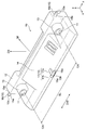
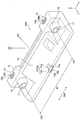
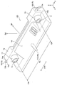
- FIG. 2 is a perspective view from above of the imaging unit 10 shown in FIG.
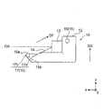
- FIG. 3 is a top view of the imaging unit 10 shown in FIG.
- FIG. 4 is a side view of the imaging unit 10 shown in FIG.
- the imaging unit 10 is a stereo camera including a pair of cameras 11 arranged in the width direction (y-axis direction) of the imaging unit 10.
- the imaging unit 10 is not limited to a stereo camera, and may be a monocular camera.
- the imaging unit 10 includes a pair of cameras 11 and a housing 12 that holds the pair of cameras 11.
- the imaging unit 10 is positioned with high accuracy so that parallel optical axes OA of the pair of cameras 11 are along the roll axis (x-axis) that is the front-rear direction of the vehicle, and the windshield WS through the bracket 20.
- the optical axis OA direction of the imaging unit 10 is a direction that intersects the mounting direction DF and the support direction DS of the imaging unit 10.
- each camera 11 includes, for example, a lens, a lens barrel, an imaging device, an imaging substrate, and the like, and is supported and fixed to the housing 12.
- the housing 12 accommodates and holds a pair of cameras 11 that are precisely positioned so that the optical axes OA are parallel to each other, and, for example, signal processing connected to an imaging circuit on an imaging board of each camera 11
- the circuit board etc. which have a circuit are accommodated.
- the housing 12 is made of, for example, a metal such as stainless steel, and has a base length BL that is a distance between the optical axes OA of the pair of cameras 11 in the width direction DW perpendicular to the optical axis OA of the pair of cameras 11. Are formed in a shape extending in one direction and having a maximum dimension in a direction parallel to the direction.
- the casing 12 defines the outer shape of the imaging unit 10, and the width direction DW that is the longitudinal direction of the casing 12 is the width direction DW of the imaging unit 10.
- the housing 12 holds a pair of cameras 11 in camera holding portions 13 provided at both ends in the width direction DW. Thereby, the base line length BL of the pair of cameras 11 of the imaging unit 10 is secured.
- the casing 12 has a height of a front portion of the vehicle, that is, a dimension in the z-axis direction of a portion on the plus side of the x-axis in accordance with the inclination of the windshield WS. Is smaller than the height in the z-axis direction of the portion on the minus side of the x-axis. That is, in the imaging unit 10, the height of the rear end portion in the attachment direction DF is lower than the height of the front end portion in the attachment direction DF. Further, the housing 12 has an inclined surface 14 between the pair of camera holding units 13 along the mounting direction DF of the imaging unit 10.
- the imaging unit 10 includes a plurality of supported portions 15 that are provided at different positions of the housing 12 and are supported by the bracket 20.
- the plurality of supported portions 15 are, for example, one end portion in the optical axis OA direction of the imaging unit 10 and both end portions in the width direction DW of the imaging unit 10 intersecting the optical axis OA direction, and the optical axis of the imaging unit 10.
- the other end in the OA direction is provided at the center of the width direction DW.
- the plurality of supported portions 15 of the imaging unit 10 include a pair of first supported portions 16 provided at the rear end portions in the optical axis OA direction of the imaging unit 10 and the light of the imaging unit 10. And a second supported portion 17 provided at a front end portion in the axis OA direction.
- the front in the optical axis OA direction of the imaging unit 10 is a direction facing the front in the traveling direction of the vehicle in the optical axis OA direction.
- the rear of the imaging unit 10 in the direction of the optical axis OA is a direction facing the rear of the traveling direction of the vehicle in the direction of the optical axis OA.
- the imaging unit 10 has a pair of first supported portions 16 at the front end portion in the optical axis OA direction, and one second supported portion 17 at the rear end portion in the optical axis OA direction. You may have.
- the imaging unit 10 may have a plurality of supported portions 15 at one end in the optical axis OA direction and at both ends in the width direction DW, and the width at the other end in the optical axis OA direction. You may have the some to-be-supported part 15 in the center part of the direction DW.
- each supported portion 15 includes a supported point 15a supported by the bracket 20 and a load point 15b that receives an urging force F acting from the bracket 20 toward the supported point 15a.
- the supported portion 15 can be a columnar shape extending in the axial direction along the width direction DW of the imaging unit 10.
- the axial direction of the columnar portion of each supported portion 15 is generally parallel to the width direction DW of the imaging unit 10, that is, the pitch axis (y-axis) of the vehicle.
- the first supported portions 16 provided at the front end in the mounting direction DF, that is, the rear end in the optical axis OA direction and at both ends in the width direction DW of the imaging unit 10, are the width of the imaging unit 10. Projecting from both side surfaces of the housing 12 toward the outside of the housing 12 in the direction DW. In the illustrated example, the pair of cameras 11 of the imaging unit 10 is disposed at both ends in the width direction W of the imaging unit 10 adjacent to the pair of first supported portions 16.
- the pair of first supported parts 16 can be provided symmetrically with respect to a center line parallel to the optical axis OA of the imaging part 10.
- the camera 11 is disposed adjacent to the first supported portion 16 means that the first supported portion 16 is provided in the vicinity of the camera 11, for example, in the vicinity of the camera holding portion 13 of the housing 12.
- the vicinity of the camera 11 means that the distance from the camera 11 is within a predetermined distance range, and is, for example, 1/2 or less of the baseline length BL, more preferably 1/3 or less, and still more preferably.
- the distance range is 1/4 or less.
- the distance between the first supported portion 16 and the camera 11 is, for example, 1/5 or less of the baseline length BL.
- the first supported portion 16 includes a supported point 15 a supported by the bracket 20 and a load point that receives an urging force F acting from the bracket 20 toward the supported point 15 a. 15b.
- the first supported portion 16 can have, for example, two supported points 15 a arranged in the optical axis OA direction and the mounting direction DF of the imaging unit 10.
- the supported point 15 a of the first supported portion 16 is located at the lower end portion of the first supported portion 16 in the support direction DS of the imaging unit 10.
- the load point 15 b of the first supported portion 16 is located at the upper end portion of the first supported portion 16 in the support direction DS of the imaging unit 10. Further, the load point 15 b of the first supported portion 16 is provided between the two supported points 15 a in the mounting direction DF of the imaging unit 10.
- the cross-sectional shape of the columnar first supported portion 16 is, for example, circular or elliptical.
- a shape having a cylindrical curved surface such as a shape or an oval shape is preferable. That is, the first supported portion 16 preferably has, for example, a cylindrical shape, an elliptical column shape, or a long cylindrical shape.
- the second supported portion 17 is provided at the rear end portion in the mounting direction DF in the imaging portion 10, that is, the front end portion in the optical axis OA direction and the central portion in the width direction DW.
- the center part in the width direction DW of the imaging unit 10 can be defined as, for example, the center in the width direction DW of the imaging unit 10 and the part closer to the center than both ends in the width direction DW of the imaging unit 10. .
- the second supported portion 17 can have, for example, a first portion 17a and a second portion 17b.
- the first portion 17a protrudes forward in the optical axis OA direction from the center of the imaging unit 10 in the width direction DW.
- the second portion 17 b extends from the front end portion of the first portion 17 a in the optical axis OA direction of the imaging unit 10 to both sides in the width direction DW of the imaging unit 10.
- the second portion 17b of the second supported portion 17 is an axis along the direction perpendicular to the mounting direction DF and the supporting direction DS of the imaging unit 10, similarly to the first supported portion 16. It is provided in a column shape extending in the direction. Moreover, it is preferable that the shape of the 2nd part 17b of the 2nd to-be-supported part 17 is a column shape, an elliptical column shape, and a long column shape, for example.
- the first portion 17a of the second supported portion 17 is connected to the central portion in the axial direction of the columnar second portion 17b and extends in a direction perpendicular to the axial direction of the second portion 17b. Thereby, as shown in FIG. 3, the 2nd to-be-supported part 17 is formed in the general T shape by the top view.
- the second supported portion 17 has a pair of supported points 15a at the lower end of the second portion 17b in the support direction DS of the imaging unit 10 and at both ends of the imaging unit 10 in the width direction DW.
- the second supported portion 17 has one load point 15b at the upper end portion in the support direction DS of the imaging unit 10 in the second portion 17b and in the center portion of the imaging unit 10 in the width direction DW. .
- the second supported portion 17 can have a pair of supported points 15a and one load point 15b between the pair of supported points 15a in the width direction DW of the imaging unit 10, for example.
- the configuration of the second supported portion 17 is not limited to the illustrated configuration.
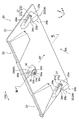
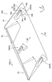
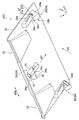
- FIG. 5 is a perspective view from below of the bracket 20 of the imaging apparatus 1 shown in FIG. 6 is a perspective view from above of the bracket 20 shown in FIG.
- the bracket 20 is an integrally molded product formed by integrally molding a resin material, for example.
- the bracket 20 includes, for example, a main body 21 on a flat plate, a pair of openings 22 that are opened in the main body 21 and expose the pair of cameras 11 of the imaging unit 10, and a pair of recesses provided on the upper surface of the main body 21.
- the light-shielding unit 23 includes a plurality of support structure units 24 that protrude from the lower surface of the main body unit 21 and support the plurality of supported units 15 of the imaging unit 10.
- the main body 21 is bonded and fixed, for example, to an upper part inside the windshield WS of the vehicle via an adhesive.
- a slight gap is formed between the front end of the main body 21 in the direction of the optical axis OA of the imaging unit 10, that is, the rear end of the main body 21 in the mounting direction DF of the imaging unit 10 and the windshield WS. Yes.
- condensation on the imaging device 1 is prevented.
- the pair of openings 22 are opened at positions corresponding to the pair of cameras 11 of the imaging unit 10 attached to the bracket 20 as shown in FIG. 1, and are surrounded by a light shielding unit 23 as shown in FIG.
- the pair of openings 22 expose the pair of cameras 11 of the imaging unit 10 toward the windshield WS so that the imaging unit 10 can photograph the front of the vehicle through the windshield WS.
- the light-shielding part 23 sinks the upper surface of the main body part 21 downward, and forwards the opening 22 toward the front of the vehicle in the direction of the optical axis OA of the imaging part 10. It is the concave part provided radially toward. As shown in FIG. 5, a portion corresponding to the light shielding portion 23 on the lower surface of the main body portion 21 protrudes downward.
- the bottom surface 23 a and the side surface 23 b of the light-shielding portion 23 surround the lower side and the side of the opening portion 22, and light is separated from the camera 11 so as not to block the field of view of the camera 11 of the imaging unit 10. It is provided in a radial pattern that is inclined away from the axis OA.
- the light shielding unit 23 shields, for example, reflected light from the interior of the vehicle and reduces the influence of the reflected light on the camera 11.
- the bracket 20 has three support structure portions 24 corresponding to the three supported portions 15 of the imaging unit 10. Note that the number of support structure portions 24 of the bracket 20 is not limited to three, and may be two or four or more, for example, corresponding to the number of supported portions 15 of the imaging unit 10.
- the plurality of support structures 24 of the bracket 20 include at least one first support structure 25. Can do. That is, all of the plurality of support structure portions 24 of the bracket 20 may be the first support structure portion 25, or three or more first support structures corresponding to the supported portion 15 of the imaging unit 10. A portion 25 may be included.
- the plurality of support structure portions 24 of the bracket 20 include at least one second support structure portion 26. Can do. That is, all of the plurality of support structure portions 24 of the bracket 20 may be the second support structure portion 26, or two or more second support structures corresponding to the supported portion 15 of the imaging unit 10. A portion 26 may be included.
- the three support structures 24 of the bracket 20 include a pair of first support structures 25 that support the pair of first supported parts 16 of the imaging unit 10 and one first of the imaging unit 10. It consists of one second support structure portion 26 that supports two supported portions 17.
- Each support structure 24 includes a biasing portion 24a that applies a biasing force F to the load point 15b of the supported portion 15, and a support portion 24b that applies a resistance against the biasing force F to the supported point 15a of the supported portion 15. And have.
- the urging unit 24a extends along the optical axis OA direction of the imaging unit 10, and more precisely, extends substantially parallel to the mounting direction DF of the imaging unit 10.
- along the direction of the optical axis OA means, for example, that the angle with respect to the optical axis OA is less than 45 °, more preferably 30 ° or less.
- one end in the optical axis OA direction of the imaging unit 10, that is, the rear end in the mounting direction DF of the imaging unit 10 is a fixed end, and the other end in the optical axis OA direction of the imaging unit 10. That is, the front end in the mounting direction DF of the imaging unit 10 is a free end.
- the distance between the free end of the urging portion 24a and the support portion 24b is such that the imaging unit 10 is supported by the bracket 20 shown in FIG. 5 rather than the state where the imaging unit 10 is supported by the bracket 20 shown in FIG. Narrow in no state.
- the urging unit 24 a is provided in a plate spring shape that is elastically deformed by receiving a force in the vertical direction that is the support direction DS of the imaging unit 10.
- the urging unit 24a urges the supported portion 15 toward the support portion 24b in a state where the imaging unit 10 is supported by the bracket 20.
- the support portion 24b faces the urging portion 24a in the mounting direction DF, which is a direction that intersects the optical axis OA direction of the imaging unit 10 and the width direction DW of the imaging unit 10, for example.
- the support unit 24b supports the supported unit 15 of the imaging unit 10 from a support direction DS that intersects the mounting direction DF of the imaging unit 10 and the optical axis OA direction.
- each support structure portion 24 has a receiving port 24c between the urging portion 24a and the support portion 24b.
- the receiving port 24c opens toward the rear of the mounting direction DF of the imaging unit 10 and receives the supported portion 15 of the imaging unit 10 in the mounting direction DF.
- the first support structure portion 25 includes the urging portion 24a, the support portion 24b, and the receiving port 24c.
- the pair of first support structures 25 can be provided symmetrically with respect to the center line of the bracket 20 in the width direction DW of the imaging unit 10 from the viewpoint of suppressing the twist of the housing 12 of the imaging unit 10.
- the urging portion 24 a of the first support structure portion 25 extends from the rear to the front of the receiving port 24 c in the mounting direction DF of the imaging unit 10.
- the support portion 24 b of the first support structure portion 25 has an engagement recess 27.
- the engaging recess 27 is provided in a concave shape in the support direction DS of the imaging unit 10 and engages the supported portion 15 of the imaging unit 10.
- the support direction DS of the imaging unit 10 in the first support structure unit 25 is the vertical direction along the vertical direction.
- the engaging recess 27 supports the two supported points 15 a of the first supported part 16 of the imaging unit 10 from below, and the urging part 24 a is applied to the load point 15 b of the first supported part 16 from above.
- the urging force F is applied.
- the support portion 24b of the first support structure portion 25 is located on the front side of the urging portion 24a in the mounting direction DF of the imaging unit 10 and on the urging portion 24a in the support direction DS of the imaging unit 10. It has a claw-like engaging portion 25a extending downward from above.
- the engaging portion 25a includes an engaging concave portion 27 provided at a lower end portion in the support direction DS of the imaging unit 10, a guide surface 25b extending from the lower side of the receiving port 24c to the receiving port 24c in the supporting direction DS of the imaging unit 10, have.
- the engagement recess 27 provided in the support portion 24b of the first support structure portion 25 is provided at the rear end portion of the mounting direction DF of the imaging unit 10 in the support direction DS (z It has the inclined surface 27a which inclines to the back of the attachment direction DF with respect to (axial direction). Further, the engaging recess 27 has an inclined surface 27b at the front end in the mounting direction DF of the imaging unit 10 that is inclined forward in the mounting direction DF of the imaging unit 10 with respect to the support direction DS of the imaging unit 10. . Due to these inclined surfaces 27a and 27b, the engaging recess 27 has a generally V-shaped shape in a side view shown in FIG.
- FIG. 7 is an enlarged sectional view taken along the line VII-VII of the second support structure portion 26 of the bracket 20 shown in FIG. FIG. 7 shows a state where the second supported structure 17 holds the second supported portion 17 of the imaging unit 10.
- the second support structure portion 26 of the bracket 20 includes the biasing portion 24a, the support portion 24b, and the receiving port 24c as described above.
- the urging portion 24a of the second support structure portion 26 extends from the rear to the front of the receiving port 24c in the mounting direction DF of the imaging unit 10.
- the second support structure portion 26 of the bracket 20 faces the width direction DW (y-axis direction) of the imaging portion 10 as shown in FIG. It has a pair of guide walls 30 extending in the up-and-down direction that is the support direction DS.
- the support portion 24 b of the second support structure portion 26 protrudes from the opposite surfaces of the pair of guide walls 30 at the lower end portion of the guide wall 30 so as to face each other in the width direction DW of the imaging unit 10.
- the pair of guide walls 30 of the second support structure section 26 are surfaces facing each other in the width direction DW of the imaging section 10, respectively, and a first guide surface 30a and a second guide, respectively. It has a surface 30b and an inlet 30c.
- the first guide surface 30a extends vertically from below the receiving port 24c that receives the second supported portion 17 of the imaging unit 10 to the receiving port 24c.
- the second guide surface 30b extends vertically with respect to the first guide surface 30a so as to face the rear side in the mounting direction DF of the imaging unit 10.
- the introduction port 30c opens downward between the first guide surface 30a and the second guide surface 30b, and receives the second supported portion 17 of the imaging unit 10 upward.
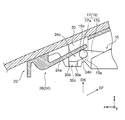
- FIG. 8 is a side view for explaining the procedure for attaching the imaging unit 10 to the bracket 20 in the imaging apparatus 1 of the present embodiment shown in FIG.
- the imaging device 1 of the present embodiment includes the imaging unit 10 that can be attached to the bracket 20 as described above.
- the imaging unit 10 includes a supported portion 15 that is supported by the bracket 20.
- the plurality of supported portions 15 include one end portion in the optical axis OA direction of the imaging unit 10 and both end portions in the width direction DW of the imaging unit 10 intersecting the optical axis OA direction, and the optical axis of the imaging unit 10.
- the other end in the OA direction is provided at the center in the width direction DW.
- the supported portion 15 includes a supported point 15a supported by the bracket 20 and a load point 15b that receives an urging force F acting from the bracket 20 toward the supported point 15a.
- the imaging device 1 having such a configuration can attach the imaging unit 10 to the bracket 20 fixed to the upper part of the windshield WS of the vehicle, for example, by the following procedure. First, the positions of the plurality of supported parts 15 of the imaging unit 10 and the plurality of support structure parts 24 of the bracket 20 are aligned. Then, when the imaging unit 10 is slid in the mounting direction DF, the plurality of supported parts 15 of the imaging unit 10 are arranged between the biasing part 24a and the support part 24b in the plurality of support structure parts 24 of the bracket 20. It is received in the receiving port 24c.
- the plurality of supported portions 15 of the imaging unit 10 After receiving the plurality of supported portions 15 of the imaging unit 10 into the receiving ports 24c of the plurality of support structure portions 24 of the bracket 20, when the imaging unit 10 is further slid in the mounting direction DF, the plurality of supported portions of the imaging unit 10 are supported.
- the part 15 moves to the front in the mounting direction DF from the receiving ports 24 c of the plurality of support structure parts 24 of the bracket 20.
- the plurality of supported portions 15 of the imaging unit 10 are arranged between the urging portions 24 a and the support portions 24 b of the plurality of support structure portions 24 of the bracket 20, and the urging portions 24 a support the imaging unit 10. Elastically deforms upward in the direction DS.
- the imaging unit 10 is attached to the bracket 20.
- the plurality of supported portions 15 of the imaging unit 10 supported by the bracket 20 are one end in the optical axis OA direction of the imaging unit 10 and the imaging unit 10.
- the both ends of the width direction DW and the other end of the image pickup unit 10 in the optical axis OA direction and the center of the image pickup unit 10 in the width direction DW are arranged.
- the plurality of supported portions 15 of the imaging unit 10 have heights in a direction substantially parallel to the bottom side generally parallel to the width direction DW of the imaging unit 10 and the mounting direction DF along the optical axis OA direction of the imaging unit 10. It is arranged at or near the vertex of the isosceles triangle.
- the imaging unit 10 can be supported by the bracket 20 in a three-point support or a state close thereto. Therefore, according to the imaging device 1 of the present embodiment, the imaging unit 10 is more stable than in the case where four or more pressed parts separated from the front, rear, left, and right of the in-vehicle camera are supported by the bracket as in the prior art. Can be supported.
- the supported portion 15 provided at one end portion in the optical axis OA direction of the imaging unit 10 and at both ends in the width direction DW of the imaging unit 10 is supported by the bracket 20, so that the roll of the imaging unit 10 is supported. Rolling that is rotation around the axis (x axis) can be suppressed. Further, by supporting the supported portion 15 at one end of the imaging unit 10 in the optical axis OA direction and the other end by the bracket 20, pitching that is rotation around the pitch axis (y-axis) of the imaging unit 10. Can be suppressed.
- the urging force F from the bracket 20 is applied by the load points 15b of the supported portions 15 provided at one end of the imaging unit 10 in the optical axis OA direction and at both ends of the imaging unit 10 in the width direction DW.
- yawing which is rotation around the yaw axis (z axis) of the imaging unit 10 can be suppressed. Therefore, according to the imaging device 1 of the present embodiment, by supporting the supported portion 15 of the imaging unit 10 by the bracket 20, the imaging unit 10 can be stabilized and positioned with high accuracy.
- each supported portion 15 of the imaging unit 10 supported by the bracket 20 is supported at a supported point 15a supported by the bracket 20, and from the bracket 20 toward the supported point 15a. And a load point 15b for receiving an urging force F acting in this manner. More specifically, the supported portion 15 of the imaging unit 10 is supported from below the support direction DS of the imaging unit 10 by the bracket 20 at the supported point 15a, and the support direction of the imaging unit 10 by the bracket 20 at the load point 15b. The biasing force F is only applied from above DS.
- the portion where the bracket 20 and the imaging unit 10 are in contact with each other can be reduced as much as possible.
- the supported portion 15 of the imaging unit 10 allows relative displacement between the bracket 20 and the support structure 24 in the mounting direction DF and the width direction DW that intersect the support direction DS of the imaging unit 10. Can do. Therefore, when the imaging unit 10 is attached to the bracket 20, stress acting on the housing 12 can be relaxed. Moreover, the relative displacement resulting from the difference in thermal expansion between the bracket 20 and the imaging unit 10 is allowed, the stress acting on the housing 12 is relaxed, and the deformation of the housing 12 is suppressed. it can. Thereby, the bad influence with respect to the imaging part 10 can be reduced.
- the plurality of supported portions 15 of the imaging unit 10 are a pair of first supported portions 16 provided at the rear end in the optical axis OA direction of the imaging unit 10. And a second supported portion 17 provided at a front end portion of the imaging unit 10 in the optical axis OA direction.
- a pair of 1st to-be-supported parts 16 are supported by the bracket 20, and rolling and pitching can be more effectively suppressed at the rear end in the optical axis OA direction of the imaging unit 10 in which the camera 11 is disposed.
- An adverse effect on the imaging unit 10 can be further reduced.
- the second supported portion 17 of the imaging unit 10 is between the pair of supported points 15a and the pair of supported points 15a in the width direction DW of the imaging unit 10.
- the bracket 20 supports the two supported points 15a of the second supported portion 17 arranged in the width direction DW of the imaging unit 10 and is provided at the center of the imaging unit 10 in the width direction DW.
- the two supported portions 17 can be supported more stably.
- the width direction DW of the imaging unit 10 is substantially parallel to the pitch axis (y axis) and substantially perpendicular to the roll axis (x axis). Therefore, the bracket 20 supports the two supported points 15a of the second supported part 17 aligned in the width direction DW of the imaging unit 10 so that the front end portion of the imaging unit 10 in the optical axis OA direction is supported. Rolling can be more effectively suppressed and the imaging unit 10 can be supported more stably.
- the second supported portion 17 of the imaging unit 10 is a first that protrudes forward from the center in the width direction DW of the imaging unit 10 in the optical axis OA direction of the imaging unit 10.
- a portion 17a and a second portion 17b extending from the front end of the first portion 17a in the optical axis OA direction to both sides in the width direction DW are provided.
- a pair of supported points 15a is provided at the lower end portion in the support direction DS of the imaging unit 10 and at both ends in the width direction DW of the imaging unit 10. it can.
- one load point 15 b can be provided at the upper end portion in the support direction DS of the imaging unit 10 and at the center portion in the width direction DW of the imaging unit 10.
- the first supported portion 16 of the imaging unit 10 has two supported points 15 a arranged in the direction of the optical axis OA of the imaging unit 10.
- the imaging unit 10 includes a pair of cameras 11 arranged in the width direction DW.
- the pair of cameras 11 are disposed at both ends of the imaging unit 10 in the width direction DW adjacent to the pair of first supported portions 16 of the imaging unit 10.
- the vicinity of the pair of cameras 11 of the imaging unit is supported by the bracket 20, the positional deviation of the pair of cameras 11 can be prevented, and the optical axes OA of the pair of cameras 11 can be precisely aligned. Therefore, the measurement accuracy such as the distance of the subject by the imaging unit 10 can be improved.
- the imaging device 1 of the present embodiment can include the bracket 20 to which the imaging unit 10 can be attached.
- the bracket 20 has a plurality of support structure portions 24 that support the plurality of supported portions 15 of the imaging unit 10.
- the support structure 24 is configured to apply a biasing force F to the load point 15b of the supported portion 15 of the imaging unit 10 and to a supported point 15a of the supported portion 15 of the imaging unit 10 against the biasing force F.
- the urging unit 24a extends along the optical axis OA direction of the imaging unit 10, one end in the optical axis OA direction is a fixed end, and the other end in the optical axis OA direction is a free end. Yes.
- the support unit 24 b faces the urging unit 24 a in the support direction DS of the imaging unit 10 that intersects the optical axis OA direction of the imaging unit 10 and the width direction DW of the imaging unit 10.
- the imaging apparatus 1 has a plurality of supported parts 15 from the support direction DS of the imaging part 10 by the urging parts 24 a and the support parts 24 b of the plurality of support structure parts 24 of the bracket 20. Can be pinched.
- the supported point 15a of the supported part 15 of the imaging unit 10 is supported by the support part 24b of the bracket 20, and the loaded point 15b of the supported part 15 of the imaging unit 10 is supported by the biasing part 24a of the bracket 20.
- the urging force F can be applied toward the support point 15a.
- the support portion 24 b of the first support structure portion 25 of the bracket 20 has an engagement recess 27 that engages the first supported portion 16 of the imaging portion 10. Yes.
- the engaging recess 27 is provided in a concave shape downward in the vertical direction, which is the support direction DS of the imaging unit 10 that intersects the mounting direction DF of the imaging unit 10.
- the first supported portion 16 of the imaging unit 10 intersects the mounting recess DF provided in the support portion 24b of the first support structure portion 25 of the bracket 20 in the mounting direction DF of the imaging unit 10. Engaging downward in the support direction DS, the movement of the imaging unit 10 in the mounting direction DF is restricted. Further, the first supported portion 16 of the imaging unit 10 is supported from both sides of the support direction DS between the engagement recess 27 and the biasing portion 24a facing the support direction DS in the first support structure portion 25. Is done. Thereby, even when vibration or impact is applied to the imaging unit 10, the first supported structure 16 of the imaging unit 10 is more stably and more reliably supported by the first support structure unit 25 of the bracket 20. Can do.
- the support direction DS of the imaging unit 10 by the bracket 20 is the vertical direction along the vertical direction.
- the engagement recessed part 27 supports the 1st to-be-supported part 16 of the imaging part 10 from the downward direction, and the urging
- the supported portion 16 is supported from above. Accordingly, the first supported structure portion 25 of the bracket 20 can stably and reliably support the first supported portion 16 of the imaging unit 10 from both sides in the vertical direction.
- the engagement recess 27 provided in the support portion 24b of the first support structure portion 25 of the bracket 20 is located at the rear end portion in the mounting direction DF of the imaging portion 10 at the imaging portion.
- 10 has an inclined surface 27a that is inclined rearward in the mounting direction DF of the imaging unit 10 with respect to the support direction DS.
- the engagement recess 27 provided in the support portion 24b of the first support structure portion 25 of the bracket 20 is located at the front end portion in the mounting direction DF of the imaging portion 10 at the imaging portion 10. It has the inclined surface 27b which inclines ahead of the attachment direction DF of the imaging part 10 with respect to this support direction DS. Thereby, among the pair of supported points 15a of the first supported portion 16 of the imaging unit 10, the supported point 15a on the front side in the mounting direction DF of the imaging unit 10 can be supported by the inclined surface 27b. .
- the second support structure portion 26 of the bracket 20 has a pair of guide walls 30 that extend vertically in the width direction DW of the imaging portion 10.
- the support portion 24 b of the second support structure portion 26 is provided on each of the pair of guide walls 30, and the urging portion 24 a is disposed between the pair of guide walls 30.
- the pair of supported points 15a of the second supported part 17 of the imaging unit 10 can be supported by the pair of support parts 24b of the second support structure part 26 of the bracket 20. Further, a single load point 15b between the pair of supported points 15a of the second supported part 17 in the width direction DW of the imaging unit 10 is provided between the pair of support parts 24b of the second support structure part 26.
- the urging force F can be applied by the urging portion 24a.
- the supported portion 15 of the imaging unit 10 has a columnar shape extending in the axial direction along the direction perpendicular to the attachment direction DF and the support direction DS. Accordingly, the supported portion 15 of the imaging unit 10 can be stably and reliably supported by the support structure portion 24 of the bracket 20 from the support direction DS that intersects the axial direction.
- the imaging unit 10 can be stably supported by the bracket 20, and is caused by the difference in the amount of thermal expansion between the bracket 20 and the imaging unit 10. It is possible to reduce the adverse effect on the imaging unit 10 to be performed.
- Embodiment 2 of the imaging device of the present invention will be described with reference to FIGS. 9 to 12.
- FIG. 9 is a side view of the image pickup apparatus 1A according to the second embodiment of the present invention.
- FIG. 10 is a perspective view from above of the imaging unit 10A of the imaging apparatus 1A shown in FIG.
- FIG. 11 is a perspective view from below of the bracket 20A of the imaging apparatus 1A shown in FIG.
- the configuration of the second supported portion 17A of the imaging unit 10A and the second support structure 26 at the front end of the bracket 20A in the optical axis OA direction of the imaging unit 10A is different from the imaging device 1 of the first embodiment. Since the other configuration of the imaging apparatus 1A of the present embodiment is the same as that of the imaging apparatus 1 of the first embodiment described above, the same parts are denoted by the same reference numerals and description thereof is omitted.
- the imaging unit 10 ⁇ / b> A of the imaging apparatus 1 ⁇ / b> A of the present embodiment has a second supported portion 17 ⁇ / b> A at the center in the width direction DW at the front end in the optical axis OA direction.
- the second supported portion 17A includes a pair of first portions 17a that protrude forward from the center in the width direction DW of the imaging unit 10A in the optical axis OA direction of the imaging unit 10A, and an optical axis OA that extends in the width direction DW.
- the second supported portion 17A includes a pair of first portions 17a projecting rearward in the attachment direction DF from the center portion in the width direction DW of the imaging portion 10A, and the attachment direction DF of the pair of first portions 17a. And a columnar second portion 17b extending in the axial direction along the direction perpendicular to the attachment direction DF and the support direction DS.
- the pair of first portions 17a extends substantially in parallel with the optical axis OA direction of the imaging unit 10A and the roll axis (x axis) of the vehicle, and the second portion 17b extends from the imaging unit 10A. It extends in an axial direction generally perpendicular to the optical axis OA direction and substantially parallel to the vehicle pitch axis (y-axis).
- the second supported portion 17A is generally U in the top view when both axial ends of the second portion 17b are connected to the rear end portions of the pair of first portions 17a in the mounting direction DF of the imaging unit 10A. It is formed in a letter shape and is formed in an annular shape having an opening between the housing 12 of the imaging unit 10A.
- the plurality of support structure portions 24 of the bracket 20 ⁇ / b> A of the imaging apparatus 1 ⁇ / b> A includes three first support structure portions 25.
- the bracket 20A has a pair of first support structures 25 at both ends in the width direction DW of the imaging unit 10A at the rear end in the optical axis OA direction of the imaging unit 10A, and the optical axis OA of the imaging unit 10A.
- One first support structure 25 is provided at the center of the imaging unit 10A in the width direction DW at the front end in the direction.
- FIG. 12 is an enlarged view of the first support structure 25 provided at the front end of the imaging unit 10A of the bracket 20A shown in FIG. 11 in the optical axis OA direction.
- FIG. 12 shows a state in which the second supported portion 17A of the imaging unit 10A is supported by the first support structure 25 as shown in FIG.
- the part 25 is supported in the same manner as the first supported part 16 of the imaging unit 10A.
- the imaging device 1A of the present embodiment not only can the same effect as the imaging device 1 of the first embodiment described above be obtained, but also the end on the front side of the bracket 20A in the optical axis OA direction of the imaging unit 10A.
- the second supported portion 17A of the imaging unit 10A can be more stably and reliably supported by the first support structure portion 25 provided in the portion.
- Embodiment 3 of the imaging device of the present invention will be described with reference to FIGS. 13 to 15.
- FIG. 13 is a side view of the imaging apparatus 1B according to Embodiment 3 of the present invention.
- FIG. 14 is a perspective view from above of the imaging unit 10B of the imaging apparatus 1B shown in FIG.
- FIG. 15 is a perspective view from below of the bracket 20B of the imaging apparatus 1B shown in FIG.
- the imaging device 1B of the present embodiment is different from the imaging device 1 of the first embodiment described above in the configuration of the first supported portion 16B of the imaging unit 10B. Since the other configuration of the imaging apparatus 1B of the present embodiment is the same as that of the imaging apparatus 1 of the first embodiment, the same parts are denoted by the same reference numerals and description thereof is omitted.
- the imaging unit 10B of the imaging device 1B of the present embodiment includes a pair of brackets 20B at both ends in the width direction DW at the rear end of the housing 12 in the optical axis OA direction. It has a pair of recessed part 18 which accommodates the lower end part of the 1st support structure part 25 of this.
- the imaging unit 10 ⁇ / b> B has a pair of first supported portions 16 ⁇ / b> B that cross the pair of recesses 18 on the upper end surface of the housing 12 in the support direction DS.
- the first supported portion 16B of the imaging unit 10B is provided in a columnar shape with the width direction DW of the imaging unit 10B as the axial direction, and both end portions in the axial direction are fixed to the housing 12. As shown in FIG. 13, the first supported portion 16B has a semi-cylindrical shape having a plane supported by the urging portion 24a of the first support structure portion 25 of the bracket 20B.
- the pair of first support structures 25 of the bracket 20B is smaller than the pair of first support structures 25 provided on the bracket 20 of the imaging device 1 of Embodiment 1 shown in FIG. It is easy to accommodate in the recess 18 of the housing 12 of the imaging unit 10B.
- the imaging device 1B of the present embodiment not only the same effect as the imaging device 1 of the first embodiment described above is obtained, but also the pair of first supported portions 16B of the imaging unit 10B has the width of the imaging unit 10B. Without projecting in the direction DW, the pair of first support structure portions 25 of the bracket 20B can be disposed on the inner side than both ends of the imaging unit 10B in the width direction DW. Therefore, the imaging device 1B can be reduced in size and weight.
- Embodiment 4 of the imaging device of the present invention will be described with reference to FIGS. 16 to 18.
- FIG. 16 is a perspective view from above of the imaging unit 10C of the imaging apparatus 1C according to the fourth embodiment of the present invention.
- FIG. 17 is a perspective view from below of the bracket 20C to which the imaging unit 10C shown in FIG. 16 can be attached.
- 18 is an enlarged perspective view showing a state in which the second supported portion 17C of the imaging unit 10C shown in FIG. 16 is supported by the bracket 20C shown in FIG.
- the imaging apparatus 1C according to the present embodiment has a configuration of the second supported portion 17C of the imaging unit 10C and a second end portion on the front side of the bracket 20C in the optical axis OA direction (x-axis direction) of the imaging unit 10C.
- the third embodiment is different from the imaging device 1 according to the first embodiment in that a third support structure 28 is provided instead of the support structure 26. Since the other configuration of the imaging apparatus 1C of the present embodiment is the same as that of the imaging apparatus 1 of the first embodiment, the same parts are denoted by the same reference numerals and description thereof is omitted.
- the imaging unit 10 ⁇ / b> C of the imaging apparatus 1 ⁇ / b> C of the present embodiment has a second end at the center in the width direction DW at the front end in the optical axis OA direction (x-axis direction). It has a supported portion 17C.
- the second supported portion 17C has a conical shape with a spherical tip at the tip that protrudes forward in the optical axis OA direction from the housing 12 of the imaging unit 10C.
- the bracket 20 ⁇ / b> C of the imaging device 1 ⁇ / b> C has a front end portion in the optical axis OA direction (x-axis direction) at the center portion in the width direction DW.
- a third support structure 28 is provided as the support structure 24 that supports the second supported part 17C. Similar to the second support structure portion 26 of the imaging device 1 of the first embodiment, the third support structure portion 28 includes an urging portion 24a, a support portion 24b, and a receiving port 24c. However, in the third support structure 28, the urging portion 24a has a rear end in the optical axis OA direction as a fixed end and a front end in the optical axis OA direction as a free end.
- the support portion 24b includes a pair of side wall portions 31 extending downward from the main body portion 21 of the bracket 20C and disposed on both sides of the biasing portion 24a, and the pair of side wall portions 31. It is formed in a gate shape having a bottom wall portion 32 connecting the lower ends of the two.
- the receiving port 24c opens forward and rearward in the optical axis OA direction, and connects the second supported portion 17C of the imaging unit 10C from the rear to the front in the optical axis OA direction. accept.
- the imaging device 1C of the present embodiment not only can the same effect as the imaging device 1 of the first embodiment described above be obtained, but also the configuration of the second supported portion 17C of the imaging unit 10C is simplified. Manufacturing can be facilitated.
- at least one of the pair of first support structure portions 15 of the bracket 20C has the side surface in the width direction DW of the housing 12 of the imaging portion 10C facing the other first support structure portion 15. You may have the 2nd biasing part 24d biased. Accordingly, the imaging unit 10C can be more stably supported by the bracket 20C.
Landscapes
- Engineering & Computer Science (AREA)
- Physics & Mathematics (AREA)
- General Physics & Mathematics (AREA)
- Multimedia (AREA)
- Signal Processing (AREA)
- Mechanical Engineering (AREA)
- Fittings On The Vehicle Exterior For Carrying Loads, And Devices For Holding Or Mounting Articles (AREA)
- Studio Devices (AREA)
- Cameras In General (AREA)
- Stereoscopic And Panoramic Photography (AREA)
- Accessories Of Cameras (AREA)
Abstract
本発明は、ブラケットによって撮像部を安定して支持することができ、ブラケットと撮像部との間の熱膨張量の差に起因する撮像部に対する悪影響を低減することができる撮像装置を提供する。本発明は、ブラケットに取り付け可能な撮像部10を備える撮像装置1。撮像部10は、ブラケットに支持される複数の被支持部15を備える。被支持部15は、撮像部10の光軸OA方向における一方の端部でかつ光軸OA方向に交差する撮像部10の幅方向DWにおける両端部と、撮像部10の光軸OA方向における他方の端部で幅方向DWの中央部と、に設けられる。被支持部15は、ブラケットによって支持される被支持点15aと、ブラケットから被支持点15aへ向けて作用する付勢力を受ける荷重点15bと、を有する。
Description
本発明は、撮像装置に関する。
従来から、車載カメラを車両のフロントガラスの内面に取り付けるための車載カメラの取付け構造に係る発明が知られている(たとえば下記特許文献1を参照)。特許文献1に記載された発明は、ブラケットおよびこのブラケットが固定されたフロントガラスの交換を要することなく、押圧力に関する保守および/または車載カメラの交換を容易にかつ能率よくかつ低廉に行うことができる車載カメラの取付け構造を提供することを課題としている(同文献、要約等を参照)。
この従来の車載カメラの取付け構造は、第1のブラケットと、これに取付けられて車載カメラを保持する第2のブラケットとを有している。第1のブラケットは、支持部および第1の逆止係合部を有している。第2のブラケットは、押圧部および第2の逆止係合部を有している。押圧部は、支持部に対し車載カメラの被押圧部を弾性的に押圧して被押圧部を支持部との間に挟止する。第2の逆止係合部は、第1の逆止係合部に係合して第2のブラケットが変位することを阻止するとともに、押圧の反力を第2のブラケットから第1のブラケットへ伝達する。
前記従来の車載カメラの取付け構造では、車載カメラの前端に近接して一対の第1の被押圧部が左右に隔置されている。また、左右一対の第2の被押圧部は、対応する第1の被押圧部から後方に隔置されている(前記特許文献1の請求項6、発明の詳細な説明の第0048段落、および図4等を参照)。
このように、前後左右に離隔した四つ以上の被押圧部において車載カメラが支持されると、たとえば車載カメラの被押圧部と第1のブラケットの支持部との位置誤差等により、車載カメラが不安定になりやすい。また、たとえばブラケットと車載カメラの筐体との間で、たとえば素材や温度の相違によって熱膨張量に差が生じると、車載カメラに応力が作用して筐体が歪み、車載カメラの性能に悪影響を与えるおそれがある。
本発明は、前記課題に鑑みてなされたものであり、ブラケットによって撮像部を安定して支持することができ、ブラケットと撮像部との間の熱膨張量の差に起因する撮像部に対する悪影響を低減することができる撮像装置を提供することを目的とする。
前記目的を達成すべく、本発明の撮像装置は、ブラケットに取り付け可能な撮像部を備える撮像装置であって、前記撮像部は、前記ブラケットに支持される複数の被支持部を備え、前記被支持部は、前記撮像部の光軸方向における一方の端部でかつ前記光軸方向に交差する前記撮像部の幅方向における両端部と、前記撮像部の前記光軸方向における他方の端部で前記幅方向の中央部と、に設けられ、前記ブラケットによって支持される被支持点と、前記ブラケットから前記被支持点へ向けて作用する付勢力を受ける荷重点と、を有する。
本発明の撮像装置は、ブラケットによって支持される撮像部の複数の被支持部が、撮像部の光軸方向の一方の端部でかつ撮像部の幅方向の両端部と、撮像部の光軸方向の他方の端部でかつ撮像部の幅方向の中央部に配置される。これにより、撮像部の複数の被支持部は、撮像部の幅方向におおむね平行な底辺と撮像部の光軸方向に沿う方向の高さを有する二等辺三角形の頂点の位置またはその近傍に配置される。したがって、従来のように車載カメラの前後左右に離隔した四つ以上の被押圧部をブラケットによって支持する場合と比較して、撮像部を複数の被支持部においてブラケットによって安定して支持することができる。
さらに、本発明の撮像装置において、ブラケットによって支持される撮像部の各々の被支持部は、ブラケットによって支持される被支持点と、ブラケットから被支持点へ向けて作用する付勢力を受ける荷重点と、を有する。これにより、ブラケットと撮像部とが接する部分を減少させることができ、撮像部をブラケットに取付けるときの応力を緩和し、またはブラケットと撮像部との間の熱膨張量の差に起因する応力を緩和して、撮像部に対する悪影響を低減することができる。
以下、図面を参照して本発明の撮像装置の実施形態を説明する。
[実施形態1]
図1は、本発明の実施形態1に係る撮像装置1の側面図である。本実施形態の撮像装置1は、たとえば自動車等の車両に搭載される車載用の撮像装置1である。撮像装置1は、たとえば車両のフロントガラスWSの上部に取付けられ、フロントガラスWSを介して車両の前方を撮影し、撮影された対象物の距離や速度を求めるために用いられる。図1を含め、各図面に車両のロール軸をx軸、ピッチ軸をy軸、ヨー軸をz軸とする直交座標系を示す。
図1は、本発明の実施形態1に係る撮像装置1の側面図である。本実施形態の撮像装置1は、たとえば自動車等の車両に搭載される車載用の撮像装置1である。撮像装置1は、たとえば車両のフロントガラスWSの上部に取付けられ、フロントガラスWSを介して車両の前方を撮影し、撮影された対象物の距離や速度を求めるために用いられる。図1を含め、各図面に車両のロール軸をx軸、ピッチ軸をy軸、ヨー軸をz軸とする直交座標系を示す。
撮像装置1は、ブラケット20に取り付け可能な撮像部10を備えている。また、撮像装置1は、この撮像部10を所定の取付け方向DFにスライドさせて取付け可能なブラケット20を備えてもよい。ブラケット20は、たとえば、平板状の本体部21が、フロントガラスWSの上部の所定の位置に、フロントガラスWSの内表面に沿って車両のロール軸(x軸)およびヨー軸(z軸)に対して傾斜して配置され、接着剤等によってフロントガラスWSの内表面に固定される。
ブラケット20に対する撮像部10の取付け方向DFは、ブラケット20の本体部21およびフロントガラスWSの傾斜におおむね沿う方向であり、車両のロール軸(x軸)およびヨー軸(z軸)に対して傾斜する方向である。なお、撮像部10の取付け方向DFにおいて、x軸方向マイナス側かつz軸方向プラス側すなわち車両の後方側かつ鉛直方向の上方側を前方とし、x軸方向プラス側かつz軸方向マイナス側すなわち車両の前方側かつ鉛直方向の下方側を後方とする。
ブラケット20による撮像部10の支持方向DSは、撮像部10の取付け方向DFに交差する方向であり、車両のヨー軸(z軸)におおむね平行な方向である。また、撮像部10の支持方向DSは、たとえば傾斜のない平坦な路面を走行する車両における鉛直方向に沿う方向である。撮像部10の取付け方向DFは、たとえば、車両のロール軸(x軸)に対する傾斜角度が、車両のヨー軸(z軸)に対する傾斜角度よりも小さくなっている。
なお、ブラケット20に対する撮像部10の取付けおよび取外しを容易にする観点から、ロール軸(x軸)におおむね平行な撮像部10の光軸OAに対する取付け方向DFの傾斜角度は、光軸OAに対するブラケット20の本体部21の傾斜角度よりも大きいことが好ましい。また、ブラケット20を車両の天井部に取付ける場合には、ブラケット20に対する撮像部10の取付け方向DFは、たとえば、車両の天井部に沿う方向とすることができる。
図2は、図1に示す撮像部10の上方からの斜視図である。図3は、図2に示す撮像部10の上面図である。図4は、図2に示す撮像部10の側面図である。図示の例において、撮像部10は、撮像部10の幅方向(y軸方向)に並んだ一対のカメラ11を備えるステレオカメラである。なお、撮像部10は、ステレオカメラに限定されず、単眼カメラであってもよい。
撮像部10は、一対のカメラ11と、この一対のカメラ11を保持する筐体12とを備えている。撮像部10は、たとえば、一対のカメラ11の互いに平行な光軸OAが、車両の前後方向であるロール軸(x軸)に沿うように高精度に位置決めされ、ブラケット20を介してフロントガラスWSに固定される。すなわち、撮像部10の光軸OA方向は、撮像部10の取付け方向DFおよび支持方向DSに交差する方向である。図示を省略するが、各カメラ11は、たとえば、レンズ、鏡筒、撮像素子、撮像基板等を備え、筐体12に支持されて固定されている。
筐体12は、光軸OAが互いに平行になるように精密に位置決めされた一対のカメラ11を収容して保持するとともに、たとえば、各カメラ11の撮像基板上の撮像回路に接続された信号処理回路を有する回路基板等を収容している。
筐体12は、たとえば、ステンレス鋼等の金属を素材とし、一対のカメラ11の光軸OAに垂直に交差する幅方向DW、すなわち一対のカメラ11の光軸OA間の距離である基線長BLに平行な方向において最大寸法を有する、一方向に延びる形状に形成されている。筐体12は、撮像部10の外形を画定しており、筐体12の長手方向である幅方向DWは、撮像部10の幅方向DWである。筐体12は、幅方向DWの両端部に設けられたカメラ保持部13に一対のカメラ11を保持している。これにより、撮像部10の一対のカメラ11の基線長BLが確保されている。
筐体12は、図1に示すように、フロントガラスWSの傾斜に合わせて、車両の前方側の部分の高さ、すなわちx軸プラス側の部分のz軸方向の寸法が、車両の後方側の部分の高さ、すなわちx軸マイナス側の部分のz軸方向の寸法よりも、小さくなっている。すなわち、撮像部10は、取付け方向DFにおける後端部の高さが、取付け方向DFにおける前端部の高さよりも低くなっている。また、筐体12は、一対のカメラ保持部13の間に、撮像部10の取付け方向DFに沿う傾斜面14を有している。
撮像部10は、筐体12の異なる位置に設けられてブラケット20に支持される複数の被支持部15を有している。複数の被支持部15は、たとえば、撮像部10の光軸OA方向における一方の端部でかつ光軸OA方向に交差する撮像部10の幅方向DWにおける両端部と、撮像部10の光軸OA方向における他方の端部で幅方向DWの中央部と、に設けられている。
図示の例において、撮像部10の複数の被支持部15は、撮像部10の光軸OA方向における後方の端部に設けられた一対の第1の被支持部16と、撮像部10の光軸OA方向における前方の端部に設けられた一つの第2の被支持部17と、を有している。ここで、撮像部10の光軸OA方向の前方とは、光軸OA方向において車両の進行方向の前方を向く方向である。また、撮像部10の光軸OA方向の後方とは、光軸OA方向において車両の進行方向の後方を向く方向である。
なお、撮像部10の複数の被支持部15の配置は、図示の例に限定されない。たとえば、撮像部10は、光軸OA方向における前方の端部に一対の第1の被支持部16を有し、光軸OA方向における後方の端部に一つの第2の被支持部17を有してもよい。また、撮像部10は、光軸OA方向における一方の端部でかつ幅方向DWにおける両端部にそれぞれ複数の被支持部15を有してもよく、光軸OA方向における他方の端部で幅方向DWの中央部に複数の被支持部15を有してもよい。
詳細については後述するが、各々の被支持部15は、ブラケット20によって支持される被支持点15aと、ブラケット20から被支持点15aへ向けて作用する付勢力Fを受ける荷重点15bと、を有している。また、被支持部15は、少なくとも一部が、撮像部10の幅方向DWに沿う軸方向に延びる柱状であることができる。図示の例において、各被支持部15の柱状の部分の軸方向は、撮像部10の幅方向DW、すなわち車両のピッチ軸(y軸)におおむね平行である。
撮像部10において、取付け方向DFの前端部すなわち光軸OA方向の後端部でかつ撮像部10の幅方向DWの両端部に設けられた第1の被支持部16は、撮像部10の幅方向DWにおいて筐体12の両側面から筐体12の外方へ向けて突出している。図示の例において、撮像部10の一対のカメラ11は、一対の第1の被支持部16に隣接して撮像部10の幅方向Wの両端部に配置されている。一対の第1の被支持部16は、撮像部10の光軸OAに平行な中心線に対して対称に設けることができる。
ここで、カメラ11が第1の被支持部16に隣接して配置されるとは、第1の被支持部16がカメラ11の近傍、たとえば筐体12のカメラ保持部13の近傍に設けられることを意味する。ここで、カメラ11の近傍とは、カメラ11からの距離が所定の距離の範囲内であることを意味し、たとえば基線長BLの1/2以下、より好ましくは1/3以下、さらに好ましくは1/4以下の距離の範囲である。なお、図示の例において、第1の被支持部16とカメラ11との距離は、たとえば基線長BLの1/5以下である。
第1の被支持部16は、図1から図4に示すように、ブラケット20によって支持される被支持点15aと、ブラケット20から被支持点15aへ向けて作用する付勢力Fを受ける荷重点15bとを有している。
第1の被支持部16は、たとえば、撮像部10の光軸OA方向および取付け方向DFに並んだ二つの被支持点15aを有することができる。第1の被支持部16の被支持点15aは、撮像部10の支持方向DSにおいて第1の被支持部16の下端部に位置している。
第1の被支持部16の荷重点15bは、撮像部10の支持方向DSにおいて第1の被支持部16の上端部に位置している。また、第1の被支持部16の荷重点15bは、撮像部10の取付け方向DFにおいて、二つの被支持点15aの間に設けられている。
第1の被支持部16の荷重点15bは、撮像部10の支持方向DSにおいて第1の被支持部16の上端部に位置している。また、第1の被支持部16の荷重点15bは、撮像部10の取付け方向DFにおいて、二つの被支持点15aの間に設けられている。
撮像部10をブラケット20によって安定的かつ確実に支持および固定するとともに、撮像部10の取付けおよび取外しを容易にする観点から、柱状の第1の被支持部16の断面形状は、たとえば円形、楕円形、長円形等、円筒状の曲面を有する形状であることが好ましい。すなわち、第1の被支持部16は、たとえば円柱状、楕円柱状、長円柱状の形状を有することが好ましい。
第2の被支持部17は、前述のように、撮像部10における取付け方向DFの後端部すなわち光軸OA方向の前端部でかつ幅方向DWの中央部に設けられている。ここで、撮像部10の幅方向DWの中央部とは、たとえば撮像部10の幅方向DWにおける中央、および、撮像部10の幅方向DWにおける両端よりも中央に近い部分と定義することができる。
第2の被支持部17は、たとえば、第1部分17aと第2部分17bとを有することができる。第1部分17aは、撮像部10の幅方向DWの中央部から光軸OA方向における前方へ突出している。第2部分17bは、撮像部10の光軸OA方向における第1部分17aの前方の端部から撮像部10の幅方向DWの両側に延びている。
また、図示の例において、第2の被支持部17の第2部分17bは、第1の被支持部16と同様に、撮像部10の取付け方向DFおよび支持方向DSに垂直な方向に沿う軸方向に延びる柱状に設けられている。また、第2の被支持部17の第2部分17bの形状は、たとえば円柱状、楕円柱状、長円柱状であることが好ましい。
第2の被支持部17の第1部分17aは、柱状の第2部分17bの軸方向の中央部に接続され、第2部分17bの軸方向に垂直な方向に延びている。これにより、第2の被支持部17は、図3に示すように、上面視でおおむねT字状に形成されている。
第2の被支持部17は、第2部分17bにおける撮像部10の支持方向DSの下端部でかつ撮像部10の幅方向DWの両端部に、一対の被支持点15aを有している。また、第2の被支持部17は、第2部分17bにおける撮像部10の支持方向DSの上端部でかつ撮像部10の幅方向DWの中央部に、一つの荷重点15bを有している。
すなわち、第2の被支持部17は、たとえば撮像部10の幅方向DWにおいて、一対の被支持点15aとこの一対の被支持点15aの間の一つの荷重点15bとを有することができる。なお、第2の被支持部17の構成は、図示の構成に限定されない。
図5は、図1に示す撮像装置1のブラケット20の下方からの斜視図である。図6は、図5に示すブラケット20の上方からの斜視図である。
ブラケット20は、たとえば、樹脂材料を一体成形することによって成形された一体成形品である。ブラケット20は、たとえば、平板上の本体部21と、本体部21に開口され撮像部10の一対のカメラ11を露出させる一対の開口部22と、本体部21の上面に凹設された一対の遮光部23と、本体部21の下面に突設されて撮像部10の複数の被支持部15を支持する複数の支持構造部24とを有している。
本体部21は、図1に示すように、たとえば車両のフロントガラスWSの内側の上部に、接着剤を介して接合されて固定される。撮像部10の光軸OA方向における本体部21の前端部、すなわち撮像部10の取付け方向DFにおける本体部21の後端部と、フロントガラスWSとの間には、わずかな隙間が形成されている。この隙間を介して空気が流れることで、撮像装置1に対する結露が防止される。
一対の開口部22は、図1に示すようにブラケット20に取付けられた撮像部10の一対のカメラ11に対応する位置に開口され、図6に示すように遮光部23によって囲まれている。一対の開口部22は、撮像部10の一対のカメラ11をフロントガラスWSに向けて露出させ、撮像部10によるフロントガラスWSを介した車両の前方の撮影を可能にしている。
遮光部23は、図6に示すように、本体部21の上面側から見て、本体部21の上面を下方へ陥没させ、開口部22から撮像部10の光軸OA方向に車両の前方へ向けて放射状に設けられた凹状の部分である。図5に示すように、本体部21の下面の遮光部23に対応する部分は、下方側へ突出している。
図6に示すように、遮光部23の底面23aおよび側面23bは、開口部22の下方と側方を囲み、撮像部10のカメラ11の視野を遮らないように、カメラ11から離れるにしたがって光軸OAから離れるように傾斜する放射状に設けられている。遮光部23は、たとえば車両の室内からの反射光を遮蔽し、カメラ11に対する反射光の影響を低減する。
複数の支持構造部24は、図1および図5に示すように、本体部21の下面に突設され、撮像部10の複数の被支持部15を支持する。図示の例において、ブラケット20は、撮像部10の三つの被支持部15に対応する三つの支持構造部24を有している。なお、ブラケット20の支持構造部24の数は、三つに限定されず、撮像部10の被支持部15の数に対応して、たとえば二つまたは四つ以上であってもよい。
また、詳細については後述するが、ブラケット20によって撮像部10を安定して確実に支持する観点から、ブラケット20の複数の支持構造部24は、少なくとも一つの第1の支持構造部25を含むことができる。すなわち、ブラケット20の複数の支持構造部24は、すべてが第1の支持構造部25であってもよいし、撮像部10の被支持部15に対応して三つ以上の第1の支持構造部25を含んでもよい。
同様に、詳細については後述するが、ブラケット20からの撮像部10の取外しを容易にする観点から、ブラケット20の複数の支持構造部24は、少なくとも一つの第2の支持構造部26を含むことができる。すなわち、ブラケット20の複数の支持構造部24は、すべてが第2の支持構造部26であってもよいし、撮像部10の被支持部15に対応して二つ以上の第2の支持構造部26を含んでもよい。
図示の例において、ブラケット20の三つの支持構造部24は、撮像部10の一対の第1の被支持部16を支持する一対の第1の支持構造部25と、撮像部10の一つの第2の被支持部17を支持する一つの第2の支持構造部26とからなっている。各々の支持構造部24は、被支持部15の荷重点15bに付勢力Fを作用させる付勢部24aと、被支持部15の被支持点15aに付勢力Fに対する抗力を作用させる支持部24bと、を有している。
付勢部24aは、撮像部10の光軸OA方向に沿って延び、より正確には、撮像部10の取付け方向DFにおおむね平行に延びている。ここで、光軸OA方向に沿うとは、たとえば光軸OAに対する角度が45°未満、より好ましくは30°以下であることを意味する。付勢部24aは、撮像部10の光軸OA方向おける一方の端部すなわち撮像部10の取付け方向DFにおける後端部が固定端とされ、撮像部10の光軸OA方向における他方の端部すなわち撮像部10の取付け方向DFにおける前端部が自由端とされている。
付勢部24aの自由端と支持部24bとの間の間隔は、図1に示すブラケット20に撮像部10が支持された状態よりも、図5に示すブラケット20に撮像部10が支持されていない状態において、狭くなっている。また、付勢部24aは、撮像部10の支持方向DSである上下方向の力を受けて弾性変形する板ばね状に設けられている。これにより、付勢部24aは、ブラケット20に撮像部10が支持された状態において、被支持部15を支持部24bへ向けて付勢している。
支持部24bは、たとえば撮像部10の光軸OA方向および撮像部10の幅方向DWに交差する方向である取付け方向DFにおいて、付勢部24aに対向している。支持部24bは、撮像部10の被支持部15を、撮像部10の取付け方向DFおよび光軸OA方向に交差する支持方向DSから支持する。
また、各々の支持構造部24は、付勢部24aと支持部24bとの間に受入口24cを有している。受入口24cは、撮像部10の取付け方向DFの後方へ向けて開口して、撮像部10の被支持部15を取付け方向DFに受け入れる。
第1の支持構造部25は、前述のように、付勢部24aと支持部24bと受入口24cとを有している。一対の第1の支持構造部25は、撮像部10の筐体12のねじれを抑制する観点から、撮像部10の幅方向DWにおけるブラケット20の中心線に対して対称に設けることができる。第1の支持構造部25の付勢部24aは、撮像部10の取付け方向DFにおいて、受入口24cの後方から前方まで延びている。第1の支持構造部25の支持部24bは、係合凹部27を有している。係合凹部27は、撮像部10の支持方向DSに凹状に設けられ、撮像部10の被支持部15を係合させる。
図1および図5に示す例では、第1の支持構造部25における撮像部10の支持方向DSは、鉛直方向に沿う上下方向である。係合凹部27は、撮像部10の第1の被支持部16の二つの被支持点15aを下方から支持し、付勢部24aは、第1の被支持部16の荷重点15bに上方から付勢力Fを作用させている。
なお、図示の例において、第1の支持構造部25の支持部24bは、撮像部10の取付け方向DFにおいて付勢部24aの前方側で、撮像部10の支持方向DSにおいて付勢部24aの上方から下方へ延びる鉤爪状の係合部25aを有している。係合部25aは、撮像部10の支持方向DSにおける下端部に設けられた係合凹部27と、撮像部10の支持方向DSにおいて受入口24cの下方から受入口24cまで延びるガイド面25bと、を有している。
また、図示の例では、第1の支持構造部25の支持部24bに設けられた係合凹部27は、撮像部10の取付け方向DFの後端部に、撮像部10の支持方向DS(z軸方向)に対して取付け方向DFの後方へ傾斜する傾斜面27aを有している。さらに、係合凹部27は、撮像部10の取付け方向DFの前端部に、撮像部10の支持方向DSに対して撮像部10の取付け方向DFの前方へ傾斜する傾斜面27bを有している。これらの傾斜面27a,27bによって、係合凹部27は、図1に示す側面視でおおむねV字状の形状を有している。
図7は、図5に示すブラケット20の第2の支持構造部26のVII-VII線に沿う拡大断面図である。なお、図7は、第2の支持構造部26に撮像部10の第2の被支持部17が保持された状態を示している。
本実施形態の撮像装置1において、ブラケット20の第2の支持構造部26は、前述のように、付勢部24aと支持部24bと受入口24cとを有している。第2の支持構造部26の付勢部24aは、撮像部10の取付け方向DFにおいて、受入口24cの後方から前方まで延びている。
なお、本実施形態の撮像装置1において、ブラケット20の第2の支持構造部26は、図5に示すように、撮像部10の幅方向DW(y軸方向)に対向し、撮像部10の支持方向DSである上下に延びる一対のガイド壁30を有している。第2の支持構造部26の支持部24bは、このガイド壁30の下端部において、一対のガイド壁30の互いに対向する面から、撮像部10の幅方向DWにおいて互いに向かい合うように突出している。
第2の支持構造部26の一対のガイド壁30は、撮像部10の幅方向DWに互いに対向する面に、図7に示すように、それぞれ、第1のガイド面30aと、第2のガイド面30bと、導入口30cとを有している。第1のガイド面30aは、撮像部10の第2の被支持部17を受け入れる受入口24cの下方から、受入口24cまで上下に延びている。第2のガイド面30bは、第1のガイド面30aに対し、撮像部10の取付け方向DFにおける後方側に対向して上下に延びている。導入口30cは、第1のガイド面30aと第2のガイド面30bとの間で下方に開口し、撮像部10の第2の被支持部17を上方へ受け入れる。
以下、本実施形態の撮像装置1の作用について説明する。図8は、図1に示す本実施形態の撮像装置1において撮像部10をブラケット20に取り付ける手順を説明する側面図である。
本実施形態の撮像装置1は、前述のように、ブラケット20に取り付け可能な撮像部10を備えている。この撮像部10は、ブラケット20に支持される被支持部15を備えている。また、複数の被支持部15は、撮像部10の光軸OA方向における一方の端部でかつ光軸OA方向に交差する撮像部10の幅方向DWにおける両端部と、撮像部10の光軸OA方向における他方の端部で幅方向DWの中央部とに設けられている。さらに、被支持部15は、ブラケット20によって支持される被支持点15aと、ブラケット20から被支持点15aへ向けて作用する付勢力Fを受ける荷重点15bとを有している。
このような構成を有する撮像装置1は、たとえば以下の手順によって、車両のフロントガラスWSの上部に固定されたブラケット20に撮像部10を取付けることができる。まず、撮像部10の複数の被支持部15とブラケット20の複数の支持構造部24との位置を合わせる。そして、撮像部10をその取付け方向DFへスライドさせると、撮像部10の複数の被支持部15が、ブラケット20の複数の支持構造部24において、付勢部24aと支持部24bとの間の受入口24cに受け入れられる。
撮像部10の複数の被支持部15をブラケット20の複数の支持構造部24の受入口24cに受け入れた後、撮像部10をさらに取付け方向DFへスライドさせると、撮像部10の複数の被支持部15が、ブラケット20の複数の支持構造部24の受入口24cよりも取付け方向DFの前方に移動する。これにより、ブラケット20の複数の支持構造部24の付勢部24aと支持部24bとの間に、撮像部10の複数の被支持部15が配置され、付勢部24aが撮像部10の支持方向DSの上方に弾性変形する。
その結果、ブラケット20の複数の支持構造部24の付勢部24aから撮像部10の複数の被支持部15の荷重点15bに対して撮像部10の支持方向DSの下方の被支持点15aへ向けて付勢力Fが作用する。また、ブラケット20の複数の支持構造部24の支持部24bから撮像部10の複数の被支持部15の被支持点15aに付勢力Fに対向する抗力が作用する。以上により、撮像部10がブラケット20へ取付けられる。
このように、本実施形態の撮像装置1は、ブラケット20によって支持される撮像部10の複数の被支持部15が、撮像部10の光軸OA方向の一方の端部でかつ撮像部10の幅方向DWの両端部と、撮像部10の光軸OA方向の他方の端部でかつ撮像部10の幅方向DWの中央部に配置される。これにより、撮像部10の複数の被支持部15は、撮像部10の幅方向DWにおおむね平行な底辺と撮像部10の光軸OA方向に沿う取付け方向DFにおおむね平行な方向の高さを有する二等辺三角形の頂点の位置またはその近傍に配置される。
すなわち、撮像部10の複数の被支持部15をブラケット20によって支持することで、撮像部10をブラケット20によって三点支持またはそれに近い状態で支持することができる。したがって、本実施形態の撮像装置1によれば、従来のように車載カメラの前後左右に離隔した四つ以上の被押圧部をブラケットによって支持する場合と比較して、撮像部10を安定して支持することができる。
また、撮像部10の光軸OA方向の一方の端部でかつ撮像部10の幅方向DWの両端部に設けられた被支持部15を、ブラケット20によって支持することで、撮像部10のロール軸(x軸)周りの回転であるローリングを抑制することができる。さらに、撮像部10の光軸OA方向の一方の端部と他方の端部の被支持部15をブラケット20によって支持することで、撮像部10のピッチ軸(y軸)周りの回転であるピッチングを抑制することができる。
加えて、撮像部10の光軸OA方向の一方の端部でかつ撮像部10の幅方向DWの両端部に設けられた被支持部15の荷重点15bによって、ブラケット20からの付勢力Fを受けることで、撮像部10のヨー軸(z軸)周りの回転であるヨーイングを抑制することができる。したがって、本実施形態の撮像装置1によれば、撮像部10の被支持部15をブラケット20によって支持することで、撮像部10を安定させ、高精度に位置決めすることができる。
また、本実施形態の撮像装置1において、ブラケット20によって支持される撮像部10の各々の被支持部15は、ブラケット20によって支持される被支持点15aと、ブラケット20から被支持点15aへ向けて作用する付勢力Fを受ける荷重点15bと、を有している。より具体的には、撮像部10の被支持部15は、被支持点15aにおいてブラケット20により撮像部10の支持方向DSの下方から支持され、荷重点15bにおいてブラケット20により撮像部10の支持方向DSの上方から付勢力Fが加えられているだけである。
これにより、ブラケット20と撮像部10とが接する部分を極力減少させることができる。また、撮像部10の被支持部15は、撮像部10の支持方向DSと交差する取付け方向DFおよび幅方向DWにおいて、ブラケット20の支持構造部24との間の相対的な変位を許容することができる。したがって、撮像部10をブラケット20に取付けるときに、筐体12に作用する応力を緩和することができる。また、ブラケット20と撮像部10との間の熱膨張量の差に起因する相対的な変位を許容して、筐体12に作用する応力を緩和し、筐体12の変形を抑制することができる。これにより、撮像部10に対する悪影響を低減することができる。
また、本実施形態の撮像装置1において、撮像部10の複数の被支持部15は、撮像部10の光軸OA方向における後方の端部に設けられた一対の第1の被支持部16と、撮像部10の光軸OA方向における前方の端部に設けられた第2の被支持部17と、を有している。これにより、一対の第1の被支持部16をブラケット20によって支持し、カメラ11が配置される撮像部10の光軸OA方向における後方の端部においてローリングおよびピッチングをより効果的に抑制でき、撮像部10に対する悪影響をより低減することができる。
また、本実施形態の撮像装置1において、撮像部10の第2の被支持部17は、撮像部10の幅方向DWにおいて、一対の被支持点15aと、この一対の被支持点15aの間の一つの荷重点15bと、を有している。これにより、ブラケット20によって、撮像部10の幅方向DWに並んだ第2の被支持部17の二つの被支持点15aを支持し、撮像部10の幅方向DWの中央部に設けられた第2の被支持部17を、より安定して支持することができる。
また、本実施形態の撮像装置1において、撮像部10の幅方向DWは、ピッチ軸(y軸)におおむね平行であり、ロール軸(x軸)におおむね垂直である。そのため、ブラケット20によって、撮像部10の幅方向DWに並んだ第2の被支持部17の二つの被支持点15aを支持することで、撮像部10の光軸OA方向における前方の端部のローリングをより効果的に抑制し、撮像部10をより安定して支持することができる。
また、本実施形態の撮像装置1において、撮像部10の第2の被支持部17は、撮像部10の幅方向DWにおける中央部から撮像部10の光軸OA方向における前方へ突出する第1部分17aと、光軸OA方向における第1部分17aの前方の端部から幅方向DWの両側に延びる第2部分17bと、を有している。これにより、第2の被支持部17の第2部分17bにおいて、撮像部10の支持方向DSにおける下端部でかつ撮像部10の幅方向DWの両端部に一対の被支持点15aを設けることができる。また、第2の被支持部17の第2部分17bにおいて、撮像部10の支持方向DSにおける上端部でかつ撮像部10の幅方向DWの中央部に一つの荷重点15bを設けることができる。
また、本実施形態の撮像装置1において、撮像部10の第1の被支持部16は、撮像部10の光軸OA方向に並んだ二つの被支持点15aを有している。これにより、撮像部10の光軸OA方向の後端部でかつ撮像部10の幅方向DWの両端部において、撮像部10の光軸OA方向におおむね垂直なピッチ軸(y軸)周りの回転であるピッチングをより効果的に抑制することができる。したがって、撮像部10をより安定して支持することができる。
また、本実施形態の撮像装置1において、撮像部10は、幅方向DWに並んだ一対のカメラ11を備えている。そして、一対のカメラ11は、撮像部10の一対の第1の被支持部16に隣接して撮像部10の幅方向DWの両端部に配置されている。これにより、撮像部の一対のカメラ11の近傍をブラケット20によって支持し、一対のカメラ11の位置ずれを防止し、一対のカメラ11の光軸OAを精密に位置合わせすることができる。したがって、撮像部10による被写体の距離等の測定精度を向上させることができる。
また、本実施形態の撮像装置1は、前述のように、撮像部10を取付け可能なブラケット20を備えることができる。そして、ブラケット20は、撮像部10の複数の被支持部15を支持する複数の支持構造部24を有している。この支持構造部24は、撮像部10の被支持部15の荷重点15bに付勢力Fを作用させる付勢部24aと、撮像部10の被支持部15の被支持点15aに付勢力Fに対する抗力を作用させる支持部24bと、を有している。この付勢部24aは、撮像部10の光軸OA方向に沿って延び、光軸OA方向おける一方の端部が固定端とされ、光軸OA方向における他方の端部が自由端とされている。また、支持部24bは、撮像部10の光軸OA方向および撮像部10の幅方向DWに交差する撮像部10の支持方向DSにおいて付勢部24aに対向している。
このような構成により、本実施形態の撮像装置1は、ブラケット20の複数の支持構造部24の付勢部24aと支持部24bとによって、撮像部10の支持方向DSから複数の被支持部15を挟持することができる。そして、ブラケット20の支持部24bによって撮像部10の被支持部15の被支持点15aを支持し、ブラケット20の付勢部24aによって撮像部10の被支持部15の荷重点15bに対し、被支持点15aへ向けて付勢力Fを作用させることができる。
また、本実施形態の撮像装置1において、ブラケット20の第1の支持構造部25の支持部24bは、撮像部10の第1の被支持部16を係合させる係合凹部27を有している。この係合凹部27は、撮像部10の取付け方向DFに交差する撮像部10の支持方向DSである上下方向において、下方に向けて凹状に設けられている。
そのため、撮像部10の第1の被支持部16は、ブラケット20の第1の支持構造部25の支持部24bに設けられた係合凹部27に対し、撮像部10の取付け方向DFに交差する支持方向DSの下方へ係合し、撮像部10の取付け方向DFの前後の移動が規制される。また、撮像部10の第1の被支持部16は、第1の支持構造部25において、支持方向DSに対向する係合凹部27と付勢部24aとの間で支持方向DSの両側から支持される。これにより、撮像部10に振動や衝撃が作用した場合でも、ブラケット20の第1の支持構造部25によって、撮像部10の第1の被支持部16をより安定してより確実に支持することができる。
また、本実施形態の撮像装置1において、ブラケット20による撮像部10の支持方向DSは、鉛直方向に沿う上下方向である。そして、ブラケット20の第1の支持構造部25において、係合凹部27は、撮像部10の第1の被支持部16を下方から支持し、付勢部24aは、撮像部10の第1の被支持部16を上方から支持する。これにより、ブラケット20の第1の支持構造部25によって、上下方向の両側から撮像部10の第1の被支持部16を安定して確実に支持することができる。
また、本実施形態の撮像装置1において、ブラケット20の第1の支持構造部25の支持部24bに設けられた係合凹部27は、撮像部10の取付け方向DFにおける後端部に、撮像部10の支持方向DSに対して撮像部10の取付け方向DFの後方へ傾斜する傾斜面27aを有している。これにより、撮像部10の第1の被支持部16の一対の被支持点15aのうち、撮像部10の取付け方向DFの後方側の被支持点15aを、傾斜面27aによって支持することができる。
また、本実施形態の撮像装置1において、ブラケット20の第1の支持構造部25の支持部24bに設けられた係合凹部27は、撮像部10の取付け方向DFにおける前端部に、撮像部10の支持方向DSに対して撮像部10の取付け方向DFの前方へ傾斜する傾斜面27bを有している。これにより、撮像部10の第1の被支持部16の一対の被支持点15aのうち、撮像部10の取付け方向DFの前方側の被支持点15aを、傾斜面27bによって支持することができる。
また、本実施形態の撮像装置1において、ブラケット20の第2の支持構造部26は、撮像部10の幅方向DWに対向して上下に延びる一対のガイド壁30を有している。第2の支持構造部26の支持部24bは、一対のガイド壁30のそれぞれに設けられ、付勢部24aは、一対のガイド壁30の間に配置されている。
これにより、撮像部10の第2の被支持部17の一対の被支持点15aを、ブラケット20の第2の支持構造部26の一対の支持部24bによって支持することができる。また、撮像部10の幅方向DWにおける第2の被支持部17の一対の被支持点15aの間の一つの荷重点15bに、第2の支持構造部26の一対の支持部24bの間の付勢部24aによって付勢力Fを作用させることができる。
また、本実施形態の撮像装置1において、撮像部10の被支持部15は、取付け方向DFおよび支持方向DSに垂直な方向に沿う軸方向に延びる柱状である。これにより、撮像部10の被支持部15を軸方向に交差する支持方向DSからブラケット20の支持構造部24によって安定して確実に支持することができる。
以上説明したように、本実施形態の撮像装置1によれば、ブラケット20によって撮像部10を安定して支持することができ、ブラケット20と撮像部10との間の熱膨張量の差に起因する撮像部10に対する悪影響を低減することができる。
[実施形態2]
以下、本発明の撮像装置の実施形態2について、図9から図12を用いて説明する。
以下、本発明の撮像装置の実施形態2について、図9から図12を用いて説明する。
図9は、本発明の実施形態2に係る撮像装置1Aの側面図である。図10は、図9に示す撮像装置1Aの撮像部10Aの上方からの斜視図である。図11は、図9に示す撮像装置1Aのブラケット20Aの下方からの斜視図である。
本実施形態の撮像装置1Aは、撮像部10Aの第2の被支持部17Aの構成と、撮像部10Aの光軸OA方向におけるブラケット20Aの前方側の端部に第2の支持構造部26に代えて第1の支持構造部25を有する点が、前述の実施形態1の撮像装置1と異なっている。本実施形態の撮像装置1Aのその他の構成は、前述の実施形態1の撮像装置1の構成と同様であるため、同様の部分には同一の符号を付して説明を省略する。
図9および図10に示すように、本実施形態の撮像装置1Aの撮像部10Aは、光軸OA方向の前方側の端部で幅方向DWの中央部に、第2の被支持部17Aを有している。第2の被支持部17Aは、撮像部10Aの幅方向DWにおける中央部から撮像部10Aの光軸OA方向における前方へ突出する一対の第1部分17aと、幅方向DWに延びて光軸OA方向における一対の第1部分17aの前方の端部を連結する第2部分17bと、を有している。
換言すると、第2の被支持部17Aは、撮像部10Aの幅方向DWの中央部から取付け方向DFの後方へ突出する一対の第1部分17aと、この一対の第1部分17aの取付け方向DFの後端に設けられ、取付け方向DFおよび支持方向DSに垂直な方向に沿う軸方向に延びる柱状の第2部分17bとを有している。
第2の被支持部17Aにおいて、一対の第1部分17aは、撮像部10Aの光軸OA方向および車両のロール軸(x軸)におおむね平行に延び、第2部分17bは、撮像部10Aの光軸OA方向におおむね垂直で車両のピッチ軸(y軸)におおむね平行な軸方向に延びている。第2の被支持部17Aは、撮像部10Aの取付け方向DFにおける一対の第1部分17aの後端部に第2部分17bの軸方向の両端部が接続されることで、上面視でおおむねU字形に形成され、撮像部10Aの筐体12との間に開口を有する環状に形成されている。
図9および図11に示すように、本実施形態の撮像装置1Aのブラケット20Aの複数の支持構造部24は、三つの第1の支持構造部25からなっている。ブラケット20Aは、撮像部10Aの光軸OA方向の後方側の端部で撮像部10Aの幅方向DWの両端部に一対の第1の支持構造部25を有し、撮像部10Aの光軸OA方向の前方側の端部で撮像部10Aの幅方向DWの中央部に一つの第1の支持構造部25を有している。
図12は、図11に示すブラケット20Aの撮像部10Aの光軸OA方向の前方側の端部に設けられた第1の支持構造部25の拡大図である。なお、図12は、図9に示すように第1の支持構造部25によって撮像部10Aの第2の被支持部17Aが支持された状態を示している。本実施形態の撮像装置1Aによれば、撮像部10Aの第2の被支持部17Aが、撮像部10Aの光軸OA方向におけるブラケット20Aの前方側の端部に設けられた第1の支持構造部25によって、撮像部10Aの第1の被支持部16と同様に支持される。
したがって、本実施形態の撮像装置1Aによれば、前述の実施形態1の撮像装置1と同様の効果を得ることができるだけでなく、撮像部10Aの光軸OA方向におけるブラケット20Aの前方側の端部に設けられた第1の支持構造部25によって撮像部10Aの第2の被支持部17Aをより安定してより確実に支持することができる。
[実施形態3]
以下、本発明の撮像装置の実施形態3について、図13から図15を用いて説明する。
以下、本発明の撮像装置の実施形態3について、図13から図15を用いて説明する。
図13は、本発明の実施形態3に係る撮像装置1Bの側面図である。図14は、図13に示す撮像装置1Bの撮像部10Bの上方からの斜視図である。図15は、図13に示す撮像装置1Bのブラケット20Bの下方からの斜視図である。
本実施形態の撮像装置1Bは、撮像部10Bの第1の被支持部16Bの構成が、前述の実施形態1の撮像装置1と異なっている。本実施形態の撮像装置1Bのその他の構成は、前述の実施形態1の撮像装置1の構成と同様であるため、同様の部分には同一の符号を付して説明を省略する。
図13および図14に示すように、本実施形態の撮像装置1Bの撮像部10Bは、光軸OA方向における筐体12の後方側の端部で幅方向DWの両端部に、ブラケット20Bの一対の第1の支持構造部25の下端部を収容する一対の凹部18を有している。撮像部10Bは、支持方向DSにおける筐体12の上方側の端面に、一対の凹部18を横断する一対の第1の被支持部16Bを有している。
撮像部10Bの第1の被支持部16Bは、撮像部10Bの幅方向DWを軸方向とする柱状に設けられ、軸方向の両端部が筐体12に固定されている。第1の被支持部16Bは、図13に示すように、ブラケット20Bの第1の支持構造部25の付勢部24aによって支持される平面を有する半円柱状の形状を有している。ブラケット20Bの一対の第1の支持構造部25は、図5に示す実施形態1の撮像装置1のブラケット20に設けられた一対の第1の支持構造部25よりも小型化され、下端部を撮像部10Bの筐体12の凹部18に収容しやすくされている。
本実施形態の撮像装置1Bによれば、前述の実施形態1の撮像装置1と同様の効果が得られるだけでなく、撮像部10Bの一対の第1の被支持部16Bが撮像部10Bの幅方向DWに突出せず、ブラケット20Bの一対の第1の支持構造部25を撮像部10Bの幅方向DWの両端よりも内側に配置することができる。したがって、撮像装置1Bを小型化および軽量化することが可能になる。
[実施形態4]
以下、本発明の撮像装置の実施形態4について、図16から図18を用いて説明する。
以下、本発明の撮像装置の実施形態4について、図16から図18を用いて説明する。
図16は、本発明の実施形態4に係る撮像装置1Cの撮像部10Cの上方からの斜視図である。図17は、図16に示す撮像部10Cを取付け可能なブラケット20Cの下方からの斜視図である。図18は、図16に示す撮像部10Cの第2の被支持部17Cが図17に示すブラケット20Cに支持された状態を示す拡大斜視図である。
本実施形態の撮像装置1Cは、撮像部10Cの第2の被支持部17Cの構成と、撮像部10Cの光軸OA方向(x軸方向)におけるブラケット20Cの前方側の端部に第2の支持構造部26に代えて第3の支持構造部28を有する点が、前述の実施形態1の撮像装置1と異なっている。本実施形態の撮像装置1Cのその他の構成は、前述の実施形態1の撮像装置1の構成と同様であるため、同様の部分には同一の符号を付して説明を省略する。
図16および図18に示すように、本実施形態の撮像装置1Cの撮像部10Cは、光軸OA方向(x軸方向)の前方側の端部で幅方向DWの中央部に、第2の被支持部17Cを有している。第2の被支持部17Cは、撮像部10Cの筐体12から光軸OA方向の前方へ突出する先端部が球面状の円錐形状を有している。
図17および図18に示すように、本実施形態の撮像装置1Cのブラケット20Cは、光軸OA方向(x軸方向)の前方側の端部で幅方向DWの中央部に、撮像部10Cの第2の被支持部17Cを支持する支持構造部24として、第3の支持構造部28を有している。第3の支持構造部28は、前述の実施形態1の撮像装置1の第2の支持構造部26と同様に、付勢部24aと支持部24bと受入口24cとを有している。ただし、第3の支持構造部28において、付勢部24aは、光軸OA方向の後方の端部が固定端とされ、光軸OA方向の前方の端部が自由端とされている。
また、第3の支持構造部28において、支持部24bは、ブラケット20Cの本体部21から下方に延びて付勢部24aの両側に配置された一対の側壁部31と、この一対の側壁部31の下端部を連結する底壁部32を有する門型の形状に形成されている。また、第3の支持構造部28において、受入口24cは、光軸OA方向の前方と後方に開口し、光軸OA方向の後方から前方へ、撮像部10Cの第2の被支持部17Cを受け入れる。
本実施形態の撮像装置1Cによれば、撮像部10Cの第2の被支持部17Cが、撮像部10Cの光軸OA方向におけるブラケット20Cの前方側の端部に設けられた第3の支持構造部28によって支持される。このとき、撮像部10Cの第2の被支持部17Cの下方側の被支持点15aが、ブラケット20Cの第3の支持構造部28の支持部24bによって支持される。また、撮像部10Cの第2の被支持部17Cの上方側の荷重点15bがブラケット20Cの第3の支持構造部28の付勢部24aから被支持点15aへ向けて作用する付勢力を受ける。
したがって、本実施形態の撮像装置1Cによれば、前述の実施形態1の撮像装置1と同様の効果を得ることができるだけでなく、撮像部10Cの第2の被支持部17Cの構成を簡略化して製造を容易にすることができる。なお、本実施形態において、ブラケット20Cの一対の第1の支持構造部15の少なくとも一方は、撮像部10Cの筐体12の幅方向DWの側面を、他方の第1の支持構造部15へ向けて付勢する第2の付勢部24dを有してもよい。これにより、ブラケット20Cによって撮像部10Cをより安定して支持することができる。
以上、図面を用いて本発明の実施の形態を詳述してきたが、具体的な構成はこの実施形態に限定されるものではなく、本発明の要旨を逸脱しない範囲における設計変更等があっても、それらは本発明に含まれるものである。
1…撮像装置、1A…撮像装置、1B…撮像装置、1C…撮像装置、10…撮像部、10A…撮像部、10B…撮像部、10C…撮像部、15…被支持部、15a…被支持点、15b…荷重点、16…第1の被支持部、17…第2の被支持部、17A…第2の被支持部、17C…第2の被支持部、17a…第1部分、17b…第2部分、20…ブラケット、20A…ブラケット、20B…ブラケット、20C…ブラケット、24…支持構造部、24a…付勢部、24b…支持部、DW…幅方向、OA…光軸
Claims (8)
- ブラケットに取り付け可能な撮像部を備える撮像装置であって、
前記撮像部は、前記ブラケットに支持される複数の被支持部を備え、
前記被支持部は、前記撮像部の光軸方向における一方の端部でかつ前記光軸方向に交差する前記撮像部の幅方向における両端部と、前記撮像部の前記光軸方向における他方の端部で前記幅方向の中央部と、に設けられ、前記ブラケットによって支持される被支持点と、前記ブラケットから前記被支持点へ向けて作用する付勢力を受ける荷重点と、を有することを特徴とする撮像装置。 - 前記複数の被支持部は、前記撮像部の前記光軸方向における後方の端部に設けられた一対の第1の被支持部と、前記撮像部の前記光軸方向における前方の端部に設けられた第2の被支持部と、を有することを特徴とする請求項1に記載の撮像装置。
- 前記第2の被支持部は、前記撮像部の前記幅方向において一対の前記被支持点と、該一対の前記被支持点の間の一つの前記荷重点と、を有することを特徴とする請求項2に記載の撮像装置。
- 前記第2の被支持部は、前記撮像部の前記幅方向における中央部から前記撮像部の前記光軸方向における前方へ突出する第1部分と、前記光軸方向における前記第1部分の前方の端部から前記幅方向の両側に延びる第2部分と、を有することを特徴とする請求項3に記載の撮像装置。
- 前記第2の被支持部は、前記撮像部の前記幅方向における中央部から前記撮像部の前記光軸方向における前方へ突出する一対の第1部分と、前記幅方向に延びて前記光軸方向における前記一対の第1部分の前方の端部を連結する第2部分と、を有することを特徴とする請求項2に記載の撮像装置。
- 前記第1の被支持部は、前記撮像部の前記光軸方向に並んだ二つの前記被支持点を有することを特徴とする請求項2に記載の撮像装置。
- 前記撮像部は、前記幅方向に並んだ一対のカメラを備え、
前記一対のカメラは、前記一対の第1の被支持部に隣接して前記撮像部の前記幅方向の両端部に配置されることを特徴とする請求項2から請求項6のいずれか一項に記載の撮像装置。 - 前記撮像部を取付け可能なブラケットを備え、
前記ブラケットは、前記複数の被支持部を支持する複数の支持構造部を有し、
前記支持構造部は、前記被支持部の前記荷重点に前記付勢力を作用させる付勢部と、前記被支持部の前記被支持点に前記付勢力に対する抗力を作用させる支持部と、を有し、
前記付勢部は、前記撮像部の前記光軸方向に沿って延び、前記光軸方向おける一方の端部が固定端とされ、前記光軸方向における他方の端部が自由端とされ、
前記支持部は、前記撮像部の前記光軸方向および前記撮像部の前記幅方向に交差する方向において前記付勢部に対向することを特徴とする請求項1に記載の撮像装置。
Priority Applications (4)
| Application Number | Priority Date | Filing Date | Title |
|---|---|---|---|
| CN201780048757.XA CN109564375A (zh) | 2016-09-21 | 2017-07-28 | 摄像装置 |
| EP17852686.9A EP3518033B1 (en) | 2016-09-21 | 2017-07-28 | Imaging device |
| US16/325,370 US10870401B2 (en) | 2016-09-21 | 2017-07-28 | Imaging device |
| JP2018540667A JP6715335B2 (ja) | 2016-09-21 | 2017-07-28 | 撮像装置 |
Applications Claiming Priority (2)
| Application Number | Priority Date | Filing Date | Title |
|---|---|---|---|
| JP2016183630 | 2016-09-21 | ||
| JP2016-183630 | 2016-09-21 |
Publications (1)
| Publication Number | Publication Date |
|---|---|
| WO2018055905A1 true WO2018055905A1 (ja) | 2018-03-29 |
Family
ID=61690814
Family Applications (1)
| Application Number | Title | Priority Date | Filing Date |
|---|---|---|---|
| PCT/JP2017/027362 Ceased WO2018055905A1 (ja) | 2016-09-21 | 2017-07-28 | 撮像装置 |
Country Status (5)
| Country | Link |
|---|---|
| US (1) | US10870401B2 (ja) |
| EP (1) | EP3518033B1 (ja) |
| JP (1) | JP6715335B2 (ja) |
| CN (1) | CN109564375A (ja) |
| WO (1) | WO2018055905A1 (ja) |
Cited By (10)
| Publication number | Priority date | Publication date | Assignee | Title |
|---|---|---|---|---|
| JP2020001586A (ja) * | 2018-06-29 | 2020-01-09 | スズキ株式会社 | 車載カメラ |
| WO2020026801A1 (ja) * | 2018-07-31 | 2020-02-06 | ソニーセミコンダクタソリューションズ株式会社 | 車載カメラの保持方法、車載カメラ、ブラケット |
| WO2021038201A1 (en) | 2019-08-23 | 2021-03-04 | Pilkington Group Limited | Windscreen |
| JP2021037948A (ja) * | 2018-06-29 | 2021-03-11 | スズキ株式会社 | 車載カメラ |
| JP2021172155A (ja) * | 2020-04-21 | 2021-11-01 | スズキ株式会社 | 車載カメラの取付構造 |
| US11292399B2 (en) * | 2019-07-24 | 2022-04-05 | Pma/Tools Ag | Carrier arrangement for a sensor housing including a clip element and a counter-bearing |
| JP2022104638A (ja) * | 2017-11-10 | 2022-07-08 | 株式会社デンソー | カメラモジュール |
| JP2023542899A (ja) * | 2020-09-30 | 2023-10-12 | ツェットエフ、フリードリッヒスハーフェン、アクチエンゲゼルシャフト | 運転者支援システム用の取付装置 |
| US11831971B2 (en) | 2018-07-31 | 2023-11-28 | Sony Semiconductor Solutions Corporation | Onboard camera |
| US11938869B2 (en) | 2018-10-02 | 2024-03-26 | Pilkington Group Limited | Windscreen |
Families Citing this family (7)
| Publication number | Priority date | Publication date | Assignee | Title |
|---|---|---|---|---|
| EP3461689B1 (en) * | 2017-09-27 | 2020-12-16 | Continental Automotive GmbH | Camera device and method for mounting a camera device for a motor vehicle |
| US10556553B2 (en) * | 2018-05-15 | 2020-02-11 | Veoneer Us, Inc. | Vehicle camera mounting interfaces |
| US11592526B2 (en) | 2018-05-15 | 2023-02-28 | Uatc, Llc | Lidar sensor assembly including dovetail joint coupling features |
| US11433827B2 (en) * | 2019-06-07 | 2022-09-06 | Volvo Car Corporation | Bracket assembly for securing a safety equipment module to a windowpane of a vehicle |
| JP7278936B2 (ja) * | 2019-12-11 | 2023-05-22 | 株式会社ニフコ | ブラケット及び車載機器取付構造 |
| GB2610384B (en) * | 2021-09-01 | 2026-04-01 | Belron Int Ltd | Camera position review for vehicle driver assistance systems |
| EP4733138A1 (en) * | 2024-10-25 | 2026-04-29 | ZF Friedrichshafen AG | Mounting bracket for a driver assist system, mounting arrangement and vehicle driver assist system |
Citations (4)
| Publication number | Priority date | Publication date | Assignee | Title |
|---|---|---|---|---|
| JP2012166615A (ja) * | 2011-02-10 | 2012-09-06 | Denso Corp | 車載カメラ |
| JP2013207571A (ja) * | 2012-03-28 | 2013-10-07 | Denso Corp | 車載カメラ |
| JP2016014564A (ja) * | 2014-07-01 | 2016-01-28 | 株式会社リコー | 撮像ユニット |
| JP2016016830A (ja) | 2014-07-10 | 2016-02-01 | トヨタ自動車株式会社 | 車載カメラの取り付け構造 |
Family Cites Families (11)
| Publication number | Priority date | Publication date | Assignee | Title |
|---|---|---|---|---|
| JP2002341432A (ja) * | 2001-05-16 | 2002-11-27 | Murakami Corp | 撮像装置 |
| CN201201556Y (zh) * | 2008-03-20 | 2009-03-04 | 上海大众汽车有限公司 | 汽车电器设备的安置装置 |
| DE102012101781B4 (de) | 2012-03-02 | 2014-07-10 | Continental Automotive Gmbh | Halterahmen für Sensorvorrichtungen in Fahrzeugen |
| JP5853795B2 (ja) * | 2012-03-19 | 2016-02-09 | 株式会社デンソー | 車載カメラ |
| JP6148080B2 (ja) * | 2013-06-18 | 2017-06-14 | トヨタ自動車株式会社 | 車載カメラの固定構造 |
| DE102014012001B4 (de) * | 2014-08-12 | 2021-07-22 | Daimler Ag | Trägervorrichtung zum Befestigen an einer Scheibe eines Kraftwagens und Kraftwagen |
| US9302629B1 (en) * | 2014-10-29 | 2016-04-05 | Ford Global Technologies, Llc | Integrated tray table for a motor vehicle |
| JP6494750B2 (ja) * | 2015-05-22 | 2019-04-03 | 株式会社ニフコ | 車載用電子機器のカバー |
| CN204687999U (zh) * | 2015-06-05 | 2015-10-07 | 东风柳州汽车有限公司 | 用于前挡风玻璃的控制器安装装置 |
| US10232798B2 (en) * | 2016-01-29 | 2019-03-19 | Veoneer Us, Inc. | Apparatuses for mounting camera arrangements on motor vehicles |
| JP6392267B2 (ja) * | 2016-03-24 | 2018-09-19 | 本田技研工業株式会社 | センサブラケット |
-
2017
- 2017-07-28 EP EP17852686.9A patent/EP3518033B1/en active Active
- 2017-07-28 US US16/325,370 patent/US10870401B2/en active Active
- 2017-07-28 CN CN201780048757.XA patent/CN109564375A/zh active Pending
- 2017-07-28 WO PCT/JP2017/027362 patent/WO2018055905A1/ja not_active Ceased
- 2017-07-28 JP JP2018540667A patent/JP6715335B2/ja active Active
Patent Citations (4)
| Publication number | Priority date | Publication date | Assignee | Title |
|---|---|---|---|---|
| JP2012166615A (ja) * | 2011-02-10 | 2012-09-06 | Denso Corp | 車載カメラ |
| JP2013207571A (ja) * | 2012-03-28 | 2013-10-07 | Denso Corp | 車載カメラ |
| JP2016014564A (ja) * | 2014-07-01 | 2016-01-28 | 株式会社リコー | 撮像ユニット |
| JP2016016830A (ja) | 2014-07-10 | 2016-02-01 | トヨタ自動車株式会社 | 車載カメラの取り付け構造 |
Non-Patent Citations (1)
| Title |
|---|
| See also references of EP3518033A4 |
Cited By (19)
| Publication number | Priority date | Publication date | Assignee | Title |
|---|---|---|---|---|
| JP7302697B2 (ja) | 2017-11-10 | 2023-07-04 | 株式会社デンソー | カメラモジュール |
| JP2022104638A (ja) * | 2017-11-10 | 2022-07-08 | 株式会社デンソー | カメラモジュール |
| JP7081338B2 (ja) | 2018-06-29 | 2022-06-07 | スズキ株式会社 | 車載カメラ |
| JP2021037948A (ja) * | 2018-06-29 | 2021-03-11 | スズキ株式会社 | 車載カメラ |
| JP2020001586A (ja) * | 2018-06-29 | 2020-01-09 | スズキ株式会社 | 車載カメラ |
| JPWO2020026801A1 (ja) * | 2018-07-31 | 2021-08-05 | ソニーセミコンダクタソリューションズ株式会社 | 車載カメラの保持方法、車載カメラ、ブラケット |
| US11831971B2 (en) | 2018-07-31 | 2023-11-28 | Sony Semiconductor Solutions Corporation | Onboard camera |
| US11945375B2 (en) | 2018-07-31 | 2024-04-02 | Sony Semiconductor Solutions Corporation | Onboard camera holding method, onboard camera, bracket |
| JP7200249B2 (ja) | 2018-07-31 | 2023-01-06 | ソニーセミコンダクタソリューションズ株式会社 | 車載カメラの保持方法、車載カメラ、ブラケット |
| WO2020026801A1 (ja) * | 2018-07-31 | 2020-02-06 | ソニーセミコンダクタソリューションズ株式会社 | 車載カメラの保持方法、車載カメラ、ブラケット |
| US11938869B2 (en) | 2018-10-02 | 2024-03-26 | Pilkington Group Limited | Windscreen |
| US11292399B2 (en) * | 2019-07-24 | 2022-04-05 | Pma/Tools Ag | Carrier arrangement for a sensor housing including a clip element and a counter-bearing |
| US20220363203A1 (en) * | 2019-08-23 | 2022-11-17 | Pilkington Group Limited | Windscreen |
| WO2021038201A1 (en) | 2019-08-23 | 2021-03-04 | Pilkington Group Limited | Windscreen |
| US11987185B2 (en) | 2019-08-23 | 2024-05-21 | Pilkington Group Limited | Windscreen |
| JP7452221B2 (ja) | 2020-04-21 | 2024-03-19 | スズキ株式会社 | 車載カメラの取付構造 |
| JP2021172155A (ja) * | 2020-04-21 | 2021-11-01 | スズキ株式会社 | 車載カメラの取付構造 |
| JP2023542899A (ja) * | 2020-09-30 | 2023-10-12 | ツェットエフ、フリードリッヒスハーフェン、アクチエンゲゼルシャフト | 運転者支援システム用の取付装置 |
| JP7808096B2 (ja) | 2020-09-30 | 2026-01-28 | ツェットエフ、フリードリッヒスハーフェン、アクチエンゲゼルシャフト | 運転者支援システム用の取付装置 |
Also Published As
| Publication number | Publication date |
|---|---|
| JP6715335B2 (ja) | 2020-07-01 |
| JPWO2018055905A1 (ja) | 2019-06-27 |
| US20190193649A1 (en) | 2019-06-27 |
| EP3518033B1 (en) | 2021-04-14 |
| EP3518033A4 (en) | 2020-04-22 |
| CN109564375A (zh) | 2019-04-02 |
| EP3518033A1 (en) | 2019-07-31 |
| US10870401B2 (en) | 2020-12-22 |
Similar Documents
| Publication | Publication Date | Title |
|---|---|---|
| JP6715335B2 (ja) | 撮像装置 | |
| JP6683818B2 (ja) | 撮像装置 | |
| CN108602468B (zh) | 用于在机动车辆上安装照相机装置的设备 | |
| KR100917514B1 (ko) | 스테레오 카메라 | |
| JP6621716B2 (ja) | ステレオカメラ | |
| US20190098184A1 (en) | Camera Module | |
| CN107153316B (zh) | 相机装置和相机模块 | |
| JP5793122B2 (ja) | 車載画像処理装置 | |
| US11067875B2 (en) | Stereo camera device | |
| JP2008286527A (ja) | 複眼測距装置 | |
| JP2009068906A (ja) | 距離測定装置 | |
| EP3614204B1 (en) | Imaging device | |
| JP7084328B2 (ja) | カメラ装置 | |
| JP2013127598A (ja) | ステレオカメラ | |
| JP6459988B2 (ja) | 車載センサ取付構造 | |
| JP2022040811A (ja) | 撮像装置 | |
| JP7822478B2 (ja) | ステレオカメラ | |
| US8165464B2 (en) | Image pickup apparatus with AF sensor unit | |
| EP3816576B1 (en) | Stereo camera device | |
| WO2022113454A1 (ja) | 情報取得装置取付けユニット |
Legal Events
| Date | Code | Title | Description |
|---|---|---|---|
| 121 | Ep: the epo has been informed by wipo that ep was designated in this application |
Ref document number: 17852686 Country of ref document: EP Kind code of ref document: A1 |
|
| ENP | Entry into the national phase |
Ref document number: 2018540667 Country of ref document: JP Kind code of ref document: A |
|
| NENP | Non-entry into the national phase |
Ref country code: DE |
|
| ENP | Entry into the national phase |
Ref document number: 2017852686 Country of ref document: EP Effective date: 20190423 |