WO2018056011A1 - スペーサおよび組電池 - Google Patents
スペーサおよび組電池 Download PDFInfo
- Publication number
- WO2018056011A1 WO2018056011A1 PCT/JP2017/031234 JP2017031234W WO2018056011A1 WO 2018056011 A1 WO2018056011 A1 WO 2018056011A1 JP 2017031234 W JP2017031234 W JP 2017031234W WO 2018056011 A1 WO2018056011 A1 WO 2018056011A1
- Authority
- WO
- WIPO (PCT)
- Prior art keywords
- spacer
- electrode tab
- bus bar
- recess
- cell
- Prior art date
- Legal status (The legal status is an assumption and is not a legal conclusion. Google has not performed a legal analysis and makes no representation as to the accuracy of the status listed.)
- Ceased
Links
Images



Classifications
-
- H—ELECTRICITY
- H01—ELECTRIC ELEMENTS
- H01M—PROCESSES OR MEANS, e.g. BATTERIES, FOR THE DIRECT CONVERSION OF CHEMICAL ENERGY INTO ELECTRICAL ENERGY
- H01M10/00—Secondary cells; Manufacture thereof
- H01M10/42—Methods or arrangements for servicing or maintenance of secondary cells or secondary half-cells
- H01M10/48—Accumulators combined with arrangements for measuring, testing or indicating the condition of cells, e.g. the level or density of the electrolyte
- H01M10/482—Accumulators combined with arrangements for measuring, testing or indicating the condition of cells, e.g. the level or density of the electrolyte for several batteries or cells simultaneously or sequentially
-
- H—ELECTRICITY
- H01—ELECTRIC ELEMENTS
- H01M—PROCESSES OR MEANS, e.g. BATTERIES, FOR THE DIRECT CONVERSION OF CHEMICAL ENERGY INTO ELECTRICAL ENERGY
- H01M50/00—Constructional details or processes of manufacture of the non-active parts of electrochemical cells other than fuel cells, e.g. hybrid cells
- H01M50/20—Mountings; Secondary casings or frames; Racks, modules or packs; Suspension devices; Shock absorbers; Transport or carrying devices; Holders
-
- H—ELECTRICITY
- H01—ELECTRIC ELEMENTS
- H01M—PROCESSES OR MEANS, e.g. BATTERIES, FOR THE DIRECT CONVERSION OF CHEMICAL ENERGY INTO ELECTRICAL ENERGY
- H01M50/00—Constructional details or processes of manufacture of the non-active parts of electrochemical cells other than fuel cells, e.g. hybrid cells
- H01M50/10—Primary casings; Jackets or wrappings
- H01M50/102—Primary casings; Jackets or wrappings characterised by their shape or physical structure
- H01M50/105—Pouches or flexible bags
-
- H—ELECTRICITY
- H01—ELECTRIC ELEMENTS
- H01M—PROCESSES OR MEANS, e.g. BATTERIES, FOR THE DIRECT CONVERSION OF CHEMICAL ENERGY INTO ELECTRICAL ENERGY
- H01M50/00—Constructional details or processes of manufacture of the non-active parts of electrochemical cells other than fuel cells, e.g. hybrid cells
- H01M50/10—Primary casings; Jackets or wrappings
- H01M50/172—Arrangements of electric connectors penetrating the casing
- H01M50/174—Arrangements of electric connectors penetrating the casing adapted for the shape of the cells
- H01M50/178—Arrangements of electric connectors penetrating the casing adapted for the shape of the cells for pouch or flexible bag cells
-
- H—ELECTRICITY
- H01—ELECTRIC ELEMENTS
- H01M—PROCESSES OR MEANS, e.g. BATTERIES, FOR THE DIRECT CONVERSION OF CHEMICAL ENERGY INTO ELECTRICAL ENERGY
- H01M50/00—Constructional details or processes of manufacture of the non-active parts of electrochemical cells other than fuel cells, e.g. hybrid cells
- H01M50/20—Mountings; Secondary casings or frames; Racks, modules or packs; Suspension devices; Shock absorbers; Transport or carrying devices; Holders
- H01M50/204—Racks, modules or packs for multiple batteries or multiple cells
- H01M50/207—Racks, modules or packs for multiple batteries or multiple cells characterised by their shape
- H01M50/211—Racks, modules or packs for multiple batteries or multiple cells characterised by their shape adapted for pouch cells
-
- H—ELECTRICITY
- H01—ELECTRIC ELEMENTS
- H01M—PROCESSES OR MEANS, e.g. BATTERIES, FOR THE DIRECT CONVERSION OF CHEMICAL ENERGY INTO ELECTRICAL ENERGY
- H01M50/00—Constructional details or processes of manufacture of the non-active parts of electrochemical cells other than fuel cells, e.g. hybrid cells
- H01M50/20—Mountings; Secondary casings or frames; Racks, modules or packs; Suspension devices; Shock absorbers; Transport or carrying devices; Holders
- H01M50/289—Mountings; Secondary casings or frames; Racks, modules or packs; Suspension devices; Shock absorbers; Transport or carrying devices; Holders characterised by spacing elements or positioning means within frames, racks or packs
- H01M50/291—Mountings; Secondary casings or frames; Racks, modules or packs; Suspension devices; Shock absorbers; Transport or carrying devices; Holders characterised by spacing elements or positioning means within frames, racks or packs characterised by their shape
-
- H—ELECTRICITY
- H01—ELECTRIC ELEMENTS
- H01M—PROCESSES OR MEANS, e.g. BATTERIES, FOR THE DIRECT CONVERSION OF CHEMICAL ENERGY INTO ELECTRICAL ENERGY
- H01M50/00—Constructional details or processes of manufacture of the non-active parts of electrochemical cells other than fuel cells, e.g. hybrid cells
- H01M50/50—Current conducting connections for cells or batteries
-
- H—ELECTRICITY
- H01—ELECTRIC ELEMENTS
- H01M—PROCESSES OR MEANS, e.g. BATTERIES, FOR THE DIRECT CONVERSION OF CHEMICAL ENERGY INTO ELECTRICAL ENERGY
- H01M50/00—Constructional details or processes of manufacture of the non-active parts of electrochemical cells other than fuel cells, e.g. hybrid cells
- H01M50/50—Current conducting connections for cells or batteries
- H01M50/543—Terminals
- H01M50/547—Terminals characterised by the disposition of the terminals on the cells
- H01M50/55—Terminals characterised by the disposition of the terminals on the cells on the same side of the cell
-
- H—ELECTRICITY
- H01—ELECTRIC ELEMENTS
- H01M—PROCESSES OR MEANS, e.g. BATTERIES, FOR THE DIRECT CONVERSION OF CHEMICAL ENERGY INTO ELECTRICAL ENERGY
- H01M50/00—Constructional details or processes of manufacture of the non-active parts of electrochemical cells other than fuel cells, e.g. hybrid cells
- H01M50/50—Current conducting connections for cells or batteries
- H01M50/543—Terminals
- H01M50/552—Terminals characterised by their shape
- H01M50/553—Terminals adapted for prismatic, pouch or rectangular cells
-
- H—ELECTRICITY
- H01—ELECTRIC ELEMENTS
- H01M—PROCESSES OR MEANS, e.g. BATTERIES, FOR THE DIRECT CONVERSION OF CHEMICAL ENERGY INTO ELECTRICAL ENERGY
- H01M50/00—Constructional details or processes of manufacture of the non-active parts of electrochemical cells other than fuel cells, e.g. hybrid cells
- H01M50/50—Current conducting connections for cells or batteries
- H01M50/572—Means for preventing undesired use or discharge
- H01M50/584—Means for preventing undesired use or discharge for preventing incorrect connections inside or outside the batteries
- H01M50/588—Means for preventing undesired use or discharge for preventing incorrect connections inside or outside the batteries outside the batteries, e.g. incorrect connections of terminals or busbars
-
- H—ELECTRICITY
- H01—ELECTRIC ELEMENTS
- H01M—PROCESSES OR MEANS, e.g. BATTERIES, FOR THE DIRECT CONVERSION OF CHEMICAL ENERGY INTO ELECTRICAL ENERGY
- H01M50/00—Constructional details or processes of manufacture of the non-active parts of electrochemical cells other than fuel cells, e.g. hybrid cells
- H01M50/50—Current conducting connections for cells or batteries
- H01M50/572—Means for preventing undesired use or discharge
- H01M50/584—Means for preventing undesired use or discharge for preventing incorrect connections inside or outside the batteries
- H01M50/59—Means for preventing undesired use or discharge for preventing incorrect connections inside or outside the batteries characterised by the protection means
- H01M50/593—Spacers; Insulating plates
-
- H—ELECTRICITY
- H01—ELECTRIC ELEMENTS
- H01M—PROCESSES OR MEANS, e.g. BATTERIES, FOR THE DIRECT CONVERSION OF CHEMICAL ENERGY INTO ELECTRICAL ENERGY
- H01M2220/00—Batteries for particular applications
- H01M2220/20—Batteries in motive systems, e.g. vehicle, ship, plane
-
- H—ELECTRICITY
- H01—ELECTRIC ELEMENTS
- H01M—PROCESSES OR MEANS, e.g. BATTERIES, FOR THE DIRECT CONVERSION OF CHEMICAL ENERGY INTO ELECTRICAL ENERGY
- H01M50/00—Constructional details or processes of manufacture of the non-active parts of electrochemical cells other than fuel cells, e.g. hybrid cells
- H01M50/50—Current conducting connections for cells or batteries
- H01M50/502—Interconnectors for connecting terminals of adjacent batteries; Interconnectors for connecting cells outside a battery casing
- H01M50/503—Interconnectors for connecting terminals of adjacent batteries; Interconnectors for connecting cells outside a battery casing characterised by the shape of the interconnectors
-
- H—ELECTRICITY
- H01—ELECTRIC ELEMENTS
- H01M—PROCESSES OR MEANS, e.g. BATTERIES, FOR THE DIRECT CONVERSION OF CHEMICAL ENERGY INTO ELECTRICAL ENERGY
- H01M50/00—Constructional details or processes of manufacture of the non-active parts of electrochemical cells other than fuel cells, e.g. hybrid cells
- H01M50/50—Current conducting connections for cells or batteries
- H01M50/502—Interconnectors for connecting terminals of adjacent batteries; Interconnectors for connecting cells outside a battery casing
- H01M50/509—Interconnectors for connecting terminals of adjacent batteries; Interconnectors for connecting cells outside a battery casing characterised by the type of connection, e.g. mixed connections
-
- Y—GENERAL TAGGING OF NEW TECHNOLOGICAL DEVELOPMENTS; GENERAL TAGGING OF CROSS-SECTIONAL TECHNOLOGIES SPANNING OVER SEVERAL SECTIONS OF THE IPC; TECHNICAL SUBJECTS COVERED BY FORMER USPC CROSS-REFERENCE ART COLLECTIONS [XRACs] AND DIGESTS
- Y02—TECHNOLOGIES OR APPLICATIONS FOR MITIGATION OR ADAPTATION AGAINST CLIMATE CHANGE
- Y02E—REDUCTION OF GREENHOUSE GAS [GHG] EMISSIONS, RELATED TO ENERGY GENERATION, TRANSMISSION OR DISTRIBUTION
- Y02E60/00—Enabling technologies; Technologies with a potential or indirect contribution to GHG emissions mitigation
- Y02E60/10—Energy storage using batteries
Definitions
- the present invention relates to a spacer and an assembled battery.
- An assembled battery that is mounted on a vehicle such as an electric vehicle and used as a power source for driving a vehicle motor.
- An assembled battery (battery module as one form) is configured by stacking unit cells (flat batteries) using a spacer (insulating plate) (see Patent Document 1).
- water droplets or a water film generated by condensation may accumulate in the gap between the unit cell and the spacer.
- Water droplets and water films cause electrical leakage due to electrical short-circuiting between members constituting the assembled battery.
- An object of the present invention is to provide a spacer and an assembled battery that can suppress leakage caused by condensation.
- the spacer for achieving the above object is used for a unit cell including a battery body including a power generation element and formed flat and an electrode tab derived from the battery body.
- the spacer has a protrusion, a recess, and an opening.
- the protrusion is formed in a convex shape and is inserted into a hole or notch provided in the electrode tab to guide the electrode tab.
- the concave portion is formed in a concave shape and is separated from the electrode tab around the base of the protrusion. The opening allows a part of the recess to communicate with the side surface.
- the assembled battery for achieving the above object has a single cell, a spacer, and a bus bar.
- the unit cell includes a battery body including a power generation element and formed flat, and an electrode tab led out from the battery body.
- the spacer includes a protrusion formed in a convex shape for guiding the electrode tab by being inserted into a hole or notch provided in the electrode tab, and a concave shape so as to be separated from the electrode tab around the base of the protrusion. And an opening that allows a part of the recess to communicate with the side surface.
- the bus bar electrically connects the electrode tabs of the different unit cells.
- FIG. 3B is an end view showing FIG. 3A from the side. It is a perspective view which shows the state which removed the bus bar holder and the bus bar from the laminated body shown in FIG.
- FIG. 4 is a state in which the first cell sub-assembly (three sets of cells connected in parallel) shown in FIG. 4 is disassembled for each cell, and the first spacer and the second spacer are removed from one (the uppermost) cell.
- FIG. 8 is a perspective view which shows a part of unit cell and a part of 1st spacer. It is a side view which shows the single battery and 1st spacer of FIG.
- FIG. 8 is a perspective view showing a first spacer of FIG. 7.
- FIG. 8 is a top view showing the first spacer of FIG. 7.
- FIG. 8 is a side view schematically showing a base end portion of an electrode tab added to the first spacer of FIG. 7.
- FIG. 8 is a side view showing the first spacer of FIG. 7.
- the direction of the assembled battery 100 is shown using arrows represented by X, Y, and Z.
- the direction of the arrow represented by X indicates the longitudinal direction of the battery pack 100.
- the direction of the arrow represented by Y indicates the short direction of the battery pack 100.
- the direction of the arrow represented by Z indicates the stacking direction of the assembled battery 100.
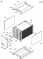
- FIG. 1 is a perspective view showing an assembled battery 100 according to the embodiment.
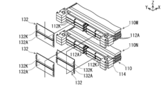
- FIG. 2 shows the assembled battery 100 shown in FIG. 1 with the pressure unit 120 (the upper pressure plate 121, the lower pressure plate 122, and the left and right side plates 123) removed, and a part of the bus bar unit 130 (the protective cover 135 and the anode). It is a perspective view which shows the state which removed the side terminal 133 and the cathode side terminal 134).
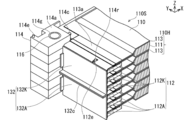
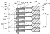
- FIG. 3A is a perspective view showing a main part in a state where the bus bar 132 is joined to the electrode tab 112 of the stacked unit cell 110 in cross section.
- FIG. 3B is an end view showing FIG. 3A from the side.
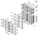
- FIG. 4 is a perspective view showing a state in which the bus bar holder 131 and the bus bar 132 are removed from the laminate 110S shown in FIG.
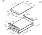
- FIG. 5 is a perspective view showing a state where the first cell sub-assembly 110M and the second cell sub-assembly 110N shown in FIG. 6 disassembles the first cell sub-assembly 110M (three sets of unit cells 110 connected in parallel) shown in FIG. 4 for each unit cell 110, and the first spacer 110 from one (top) unit cell 110 of the first cell sub-assembly 110M.
- It is a perspective view which shows the state which removed 114 and the 2nd spacer 115.
- FIG. 7 is a perspective view showing a part of the unit cell 110 and a part of the first spacer 114.
- FIG. 8 is a side view showing the unit cell 110 and the first spacer 114 of FIG.
- FIG. 9 is a perspective view showing the first spacer 114 of FIG.
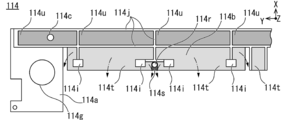
- FIG. 10 is a top view showing the first spacer 114 of FIG.
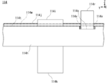
- FIG. 11 is a side view schematically showing the base end portion 112c of the electrode tab 112 added to the first spacer 114 of FIG.
- FIG. 12 is a side view showing the first spacer 114 of FIG.
- the spacer (first spacer 114) is generally derived from the battery body 110 ⁇ / b> H that includes the power generation element 111 and is formed flat, and the battery body 110 ⁇ / b> H.
- the unit cell 110 provided with the electrode tabs 112 (the anode side electrode tab 112A and the cathode side electrode tab 112K).
- the first spacer 114 has a protrusion (boss 114r), a recess (first recess 114s), and an opening (first opening 114v).
- the boss 114r is formed in a convex shape and is inserted into a hole 112e or a notch provided in the electrode tab 112 to guide the electrode tab 112.
- the first recess 114s is formed in a concave shape and is separated from the electrode tab 112 around the base of the boss 114r.
- the first opening 114v allows a part of the first recess 114s to communicate with the side surface.
- the assembled battery 100 includes a single cell 110, a spacer (first spacer 114), and a bus bar 132, as outlined.
- the unit cell 110 includes a battery body 110H that includes the power generation element 111 and is formed flat, and electrode tabs 112 (an anode side electrode tab 112A and a cathode side electrode tab 112K) that are led out from the battery body 110H.
- the first spacer 114 is inserted into a hole 112e or a notch provided in the electrode tab 112 to form a protruding portion (boss 114r) that guides the electrode tab 112, and the electrode tab 112 around the base of the boss 114r.
- first recess 114s formed in a concave shape so as to be separated from the center, and an opening (first opening 114v) that allows a part of the first recess 114s to communicate with the side surface.
- the bus bar 132 electrically connects the electrode tabs 112 of different unit cells 110.
- a plurality of assembled batteries 100 are mounted on a vehicle such as an electric vehicle and used as a power source for driving a vehicle motor.
- the assembled battery 100 is configured such that a stacked body 110 ⁇ / b> S formed by stacking a plurality of single cells 110 is electrically connected by a bus bar unit 130 in a state where the stacked body 110 ⁇ / b> S is pressurized by the pressure unit 120.
- each configuration of the assembled battery 100 including the spacers (the first spacer 114 and the second spacer 115) will be described.
- the stacked body 110 ⁇ / b> S includes a first cell sub-assembly 110 ⁇ / b> M composed of three unit cells 110 electrically connected in parallel and a second cell sub-assembly 110 ⁇ / b> N composed of three unit cells 110 electrically connected in parallel. Alternately connected in series.
- the first cell sub-assembly 110 ⁇ / b> M includes three unit cells 110 positioned in the first stage (lowermost stage), the third stage, the fifth stage, and the seventh stage (uppermost stage) in the assembled battery 100. It corresponds to.
- the second cell sub-assembly 110 ⁇ / b> N corresponds to the three unit cells 110 located in the second, fourth, and sixth stages in the assembled battery 100.
- the first cell sub-assembly 110M and the second cell sub-assembly 110N have the same configuration. However, the first cell sub-assembly 110M and the second cell sub-assembly 110N have three anode-side electrode tabs 112A and three cathode-side electrode tabs 112K by replacing the top and bottom of the three unit cells 110 as shown in FIGS. Are arranged alternately along the Z direction.
- the single battery 110 corresponds to, for example, a lithium ion secondary battery.
- a plurality of unit cells 110 are connected in series in order to satisfy the specification of the drive voltage of the vehicle motor.
- a plurality of single cells 110 are connected in parallel in order to secure the capacity of the battery and extend the travel distance of the vehicle.
- the unit cell 110 includes a battery body 110 ⁇ / b> H that is flat and includes a power generation element 111 that performs charging and discharging, an electrode tab 112 that faces the power generation element 111 to the outside, and the power generation element 111.
- the laminate film 113 to be stopped is included.
- the power generation element 111 supplies electric power by discharging electric power to a vehicle motor or the like after charging electric power from an outdoor charging stand or the like.
- the power generation element 111 is configured by stacking a plurality of sets of anodes and cathodes separated by a separator.
- the electrode tab 112 faces the power generation element 111 to the outside.
- the electrode tab 112 includes an anode side electrode tab 112A and a cathode side electrode tab 112K.
- the proximal end side of the anode side electrode tab 112A is joined to all the anodes included in one power generation element 111.
- the anode-side electrode tab 112A is formed from a thin plate and is made of aluminum in accordance with the characteristics of the anode.
- the base end side of the cathode side electrode tab 112K is joined to all the cathodes included in one power generation element 111.
- the cathode-side electrode tab 112K is formed from a thin plate and is made of copper in accordance with the characteristics of the cathode.
- the electrode tab 112 is formed in an L shape as shown in FIGS. 3B, 7 and 8.
- the base end portion 112c of the electrode tab 112 is supported by the contact portions (the first contact portion 114i and the second contact portion 114j) of the first spacer 114.
- the tip 112d of the electrode tab 112 is refracted along the lower side in the Z direction, and faces the side surface (contact surface 114h) of the first spacer 114.
- the shape of the tip 112d of the electrode tab 112 is not limited to the L shape.
- the electrode tab 112 may be formed in a U shape by further extending the distal end portion 112d and folding the extended portion toward the power generation element 111 side.
- the base end portion 112c of the electrode tab 112 may be formed in a wave shape or a curved shape.
- the tip 112 d of the electrode tab 112 is in surface contact with the bus bar 132.
- the electrode tab 112 includes a hole 112e in the central portion 112f along the width direction.
- the hole 112e is formed in a long shape from the base end portion 112c to the tip end portion 112d of the electrode tab 112.
- the hole 112e of the electrode tab 112 allows the boss 114r of the first spacer 114 to be inserted.
- the laminate film 113 is a pair, and seals the battery body 110H by sandwiching it from the top and bottom along the Z direction.
- the pair of laminate films 113 lead out the anode-side electrode tab 112A and the cathode-side electrode tab 112K from the gap between the one end portions 113a along the Y direction toward the outside.
- the laminate film 113 includes a sheet-like metal layer 113M and a sheet-like insulating layer 113N that covers and insulates the metal layer 113M from both sides.
- the unit cell 110 is supported by a pair of spacers (first spacer 114 and second spacer 115) as shown in FIG. Laminated.
- the unit cells 110 are arranged at regular intervals along the Z direction.
- the first spacer 114 supports the unit cell 110 on the side provided with the electrode tab 112.
- the second spacer 115 supports the unit cell 110 on the side not provided with the electrode tab 112 so as to face the first spacer 114 in the X direction of the unit cell 110.
- the first spacer 114 is formed of a long plate shape having irregularities and is made of reinforced plastics having insulating properties.
- the first spacer 114 is provided so as to face the one end 113 a side of the pair of laminate films 113.
- the first spacer 114 supports one end of the unit cell 110 by the contact portions (the first contact portion 114i and the second contact portion 114j).
- the first spacer 114 includes a pair of support surfaces 114b along the Y direction.
- the first spacer 114 includes a contact surface 114h on a side surface adjacent to the support surface 114b and extending along the Z direction. As shown in FIG. 3B, the contact surface 114h is in contact with the tip 112d of the electrode tab 112 and positions the tip 112d along the X direction.
- the first spacer 114 has a convex first contact portion 114i that protrudes in a rectangular shape upward from the flat support surface 114b along the Z direction.
- a plurality are provided along the Y direction.
- the first contact portion 114i supports the base end portion 112c of the electrode tab 112 of the unit cell 110 from below.
- a total of four first contact portions 114i are provided, two at the center of the support surface 114b and two at the center of the support surface 114b, and one at each end of the support surface 114b.
- the first contact portion 114i supports the central portion 112f, the one end portion 112g, and the other end portion 112h along the width direction of the electrode tab 112.
- the first spacer 114 includes a convex boss 114r at the center of each support surface 114b.
- the boss 114r is inserted into the hole 112e opened in the central portion 112f of the electrode tab 112 to restrict the position of the electrode tab 112.
- the boss 114r is caulked and fixed to a portion around the hole 112e of the electrode tab 112 as indicated by a dotted line in FIG.
- the boss 114r is caulked by heating and pressing the boss 114r to deform it into a hemisphere.
- the first spacer 114 includes a first recess 114s in which a support surface 114b positioned around the base end of the boss 114r is recessed in an annular shape around the boss 114r. Yes. A part of the first recess 114s faces the contact surface 114h. The first recess 114 s faces the electrode tab 112 of the unit cell 110, but is separated from the electrode tab 112.
- the first spacer 114 is provided with a convex second abutting portion 114j protruding in an annular shape from the respective support surfaces 114b upward in the Z direction.
- the second contact portion 114j partially supports the one end portion 113a of the laminate film 113 of the unit cell 110.
- the second contact portions 114j are lower in height than the first contact portions 114i.
- An end portion of the annular second contact portion 114j is connected to each first contact portion 114i.
- the first spacer 114 includes a second recess 114t in a portion partitioned by the annular second contact portion 114j.
- the second recess 114t is formed in a concave shape having the support surface 114b as a bottom surface and the second contact portion 114j as a side surface. A part of the second recess 114t faces the contact surface 114h.
- the second recess 114t faces the one end 113a of the laminate film 113 and the electrode tab 112 of the unit cell 110, but is separated from them.
- the first spacer 114 is provided with a third recess 114u in a portion partitioned on four sides by an annular second contact portion 114j.
- the third recess 114u is formed in a concave shape with the support surface 114b as a bottom surface and the second contact portion 114j as a side surface.
- the third recess 114u faces the one end 113a of the laminate film 113 and the electrode tab 112 of the unit cell 110, but is separated from them.
- the gap from the recess (the first recess 114s and the second recess 114t) to the side surface (contact surface 114h) of the first spacer 114 functions as a drainage channel.
- the assembled battery 100 does not decrease the insulation resistance even when water droplets or a water film is generated due to condensation, and prevents the constituent members from being electrically short-circuited or short-circuited.
- the depth of the recesses (the first recess 114s and the second recess 114t) is appropriately determined based on the amount of water generated by condensation and the surface tension of the water.
- an insulating member is provided between the first spacer 114 and the single battery 110 and the configuration in which the insulating member is forcibly insulated is adopted, the assembled battery 100 is increased in size and the manufacturing cost is increased.
- the first spacer 114 includes a pair of connecting pins 114c projecting upward at both ends along the Y direction of the support surface 114b.
- the pair of connecting pins 114c has a columnar shape, and the unit cell 110 is positioned by being inserted into connecting holes 113c opened at both ends along the Y direction of the one end 113a of the laminate film 113.
- the plurality of first spacers 114 are in contact with the upper surface 114a of one first spacer 114 and the lower surface 114d of another first spacer 114. As shown in FIG. 3B, the plurality of first spacers 114 are positioned so as to open to cylindrical positioning pins 114e protruding from the upper surface 114a of one first spacer 114 and lower surfaces 114d of the other first spacers 114. By positioning the holes 114f, they are positioned with respect to each other.
- the first spacer 114 is a rectangular parallelepiped pressing portion 114k that protrudes downward in the Z direction so as to face the first contact portion 114i along the Z direction. It has. As shown in FIG. 3B, the pressing portion 114k of the other first spacer 114 positioned relatively upward and the first contact portion 114i of the first spacer 114 positioned relatively lower The electrode tab 112 supported by the first spacer 114 is sandwiched and fixed.
- the first spacer 114 has locating holes 114g at both ends along the Y direction. Locating hole 114g inserts a bolt that connects the plurality of assembled batteries 100 while positioning them in the Z direction.
- the second spacer 115 does not need to support the electrode tab 112, the first spacer 114 is simplified.
- the second spacer 115 has a contact portion (second contact portion) that supports the other end portion 113 b of the laminate film 113 and the other end portion of the unit cell 110, as with the first spacer 114.
- 113b facing recesses (second recess and third recess), positioning pins 114e for positioning the second spacers, connecting pins 115c for positioning the single cells 110, and positioning of the plurality of assembled batteries 100
- a locate hole 115g for inserting a bolt to be connected is provided.
- the hollow spacer 116 is a so-called collar.
- the hollow spacer 116 is formed in a cylindrical shape and is made of a metal having sufficient strength.
- the hollow spacer 116 is inserted into the locate hole 114g of the first spacer 114 and the locate hole 115g of the second spacer 115, respectively.
- the hollow spacer 116 reinforces the first spacer 114 and the second spacer 115 by inserting a bolt that connects the plurality of assembled batteries 100 while positioning them.
- the configuration of the pressure unit 120 will be described in detail.
- the pressurizing unit 120 includes an upper pressurizing plate 121 and a lower pressurizing plate 122 that pressurize the power generation element 111 of each unit cell 110 of the stacked body 110S from above and below, and an upper pressurizing plate 121 and a lower part that pressurize the stacked body 110S.
- a pair of side plates 123 for fixing the pressure plate 122 is included.
- the upper pressure plate 121 and the lower pressure plate 122 sandwich and hold the plurality of unit cells 110 constituting the stacked body 110 ⁇ / b> S from above and below, and generate the power generation element of each unit cell 110.
- 111 is pressurized.
- the upper pressure plate 121 is formed in a plate shape having unevenness and is made of a metal having sufficient rigidity.
- the upper pressure plate 121 is provided on a horizontal plane.
- the upper pressure plate 121 includes a pressure surface 121 a that pressurizes the power generation element 111 downward.
- the pressing surface 121a is formed flat and protrudes downward from the central portion of the upper pressing plate 121.
- the upper pressure plate 121 includes a locating hole 121b into which a bolt for connecting the assembled batteries 100 is inserted.
- the locate hole 121b is formed of a through hole and opens at the four corners of the upper pressure plate 121.
- the lower pressure plate 122 has the same shape as the upper pressure plate 121 and is provided so as to reverse the top and bottom of the upper pressure plate 121. Similar to the upper pressure plate 121, the lower pressure plate 122 is a locating hole into which a pressure surface 122 a that pressurizes the power generation element 111 upward and bolts that connect the battery packs 100 while positioning them in the Z direction are inserted. 122b.
- the pair of side plates 123 fixes the upper pressure plate 121 and the lower pressure plate 122 in a state where the stacked body 110S is pressurized. That is, the pair of side plates 123 maintains a constant distance between the upper pressure plate 121 and the lower pressure plate 122. Further, the pair of side plates 123 covers and protects the side surfaces of the stacked unit cells 110 along the X direction.
- the side plate 123 is formed in a flat plate shape and is made of metal.
- the pair of side plates 123 are provided upright so as to face both side surfaces along the X direction of the stacked unit cells 110.
- the pair of side plates 123 are welded to the upper pressure plate 121 and the lower pressure plate 122.
- bus bar unit 130 The configuration of the bus bar unit 130 will be described in detail.
- the bus bar unit 130 includes a bus bar holder 131 that integrally holds a plurality of bus bars 132, a bus bar 132 that electrically connects the electrode tabs 112 of the unit cells 110 arranged vertically, and a plurality of the unit cells 110 that are electrically connected.
- An anode side terminal 133 that causes the anode-side termination to face the external input / output terminal, a cathode-side terminal 134 that faces the cathode-side termination of the plurality of electrically connected unit cells 110 to the external input / output terminal, and a bus bar
- a protective cover 135 for protecting 132 and the like is included.
- the bus bar holder 131 integrally holds a plurality of bus bars 132.
- the bus bar holder 131 integrally holds a plurality of bus bars 132 in a matrix so as to face the electrode tabs 112 of each unit cell 110 of the stacked body 110S.
- the bus bar holder 131 is made of an insulating resin and has a frame shape.
- the bus bar holder 131 is a pair of support columns that stand up along the Z direction so as to be positioned on both sides in the longitudinal direction of the first spacer 114 that supports the electrode tab 112 of the unit cell 110. Each part 131a is provided.
- the pair of support columns 131 a are fitted to the side surfaces of the first spacer 114.
- the pair of support columns 131a are L-shaped when viewed along the Z direction, and are formed in a plate shape extending along the Z direction.
- the bus bar holder 131 is provided with a pair of auxiliary support columns 131b that stand up along the Z direction so as to be positioned near the center of the first spacer 114 in the longitudinal direction.
- the pair of auxiliary struts 131b are formed in a plate shape extending along the Z direction.
- the bus bar holder 131 includes insulating portions 131 c that protrude between the bus bars 132 adjacent in the Z direction.
- the insulating part 131c is formed in a plate shape extending along the Y direction.
- Each insulating part 131c is provided horizontally between the auxiliary support part 131b and the auxiliary support part 131b.
- the insulating part 131c prevents discharge by insulating between the bus bars 132 adjacent in the Z direction.
- the bus bar holder 131 may be formed by joining the supporting column 131a, the auxiliary supporting column 131b, and the insulating portion 131c formed independently of each other, or the supporting column 131a, the auxiliary supporting column 131b, and the insulating portion 131c are integrally formed. You may form and comprise.
- the bus bar 132 electrically connects the electrode tabs 112 of the unit cells 110 arranged vertically.
- the bus bar 132 electrically connects the anode side electrode tab 112 ⁇ / b> A of one unit cell 110 and the cathode side electrode tab 112 ⁇ / b> K of another unit cell 110.
- the bus bar 132 electrically connects, for example, three anode-side electrode tabs 112A arranged above and below the first cell sub-assembly 110M and three cathode-side electrode tabs 112K arranged above and below the second cell sub-assembly 110N. Connect to.
- the bus bar 132 connects three anode side electrode tabs 112A of the first cell sub-assembly 110M in parallel and connects three cathode side electrode tabs 112K of the second cell sub-assembly 110N in parallel. . Further, the bus bar 132 connects three anode side electrode tabs 112A of the first cell sub-assembly 110M and three cathode side electrode tabs 112K of the second cell sub-assembly 110N in series. The bus bar 132 is laser-welded to the anode side electrode tab 112A of one unit cell 110 and the cathode side electrode tab 112K of another unit cell 110.
- the bus bar 132 is configured by joining an anode side bus bar 132A and a cathode side bus bar 132K.
- the anode-side bus bar 132A and the cathode-side bus bar 132K have the same shape, and are formed in an L shape.
- the bus bar 132 is integrated by a joining portion 132 c formed by joining one end of the anode-side bus bar 132 ⁇ / b> A that is refracted and one end of the cathode-side bus bar 132 ⁇ / b> K that is refracted. As shown in FIG.
- the anode side bus bar 132 ⁇ / b> A and the cathode side bus bar 132 ⁇ / b> K constituting the bus bar 132 include side portions 132 d that join the bus bar holder 131 at both ends along the Y direction.
- the anode-side bus bar 132A is made of aluminum, like the anode-side electrode tab 112A of the unit cell 110.
- the cathode-side bus bar 132K is made of copper, like the cathode-side electrode tab 112K of the unit cell 110.
- the anode-side bus bar 132A and the cathode-side bus bar 132K made of different metals are joined to each other by ultrasonic joining to form a joined portion 132c.
- the bus bar 132 located at the upper right in the drawing of FIG. 4 corresponds to the end of the anode side of 21 unit cells 110 (3 parallel 7 series), and from only the anode side bus bar 132A. It is composed.
- the anode-side bus bar 132A is laser-bonded to the anode-side electrode tab 112A of the uppermost three unit cells 110 among the stacked unit cells 110.
- the bus bar 132 located at the lower left in the drawing of FIG. 4 corresponds to the terminal end on the cathode side of the twenty-one unit cells 110 (three parallel seven series), and from only the cathode side bus bar 132K. It is composed.
- the cathode-side bus bar 132K is laser-bonded to the cathode-side electrode tab 112K of the lowermost three unit cells 110 among the stacked unit cells 110.
- the anode side terminal 133 has the anode-side terminations of a plurality of electrically connected unit cells 110 facing an external input / output terminal. As shown in FIG. 2, the anode-side terminal 133 is joined to the anode-side bus bar 132A located at the upper right in the figure among the bus bars 132 arranged in a matrix.
- the anode side terminal 133 is formed in a plate shape in which both ends are refracted, and is made of a metal having conductivity.
- the cathode side terminal 134 has the terminal on the cathode side of a plurality of electrically connected unit cells 110 facing an external input / output terminal. As shown in FIG. 2, the cathode side terminal 134 is joined to the cathode side bus bar 132K located in the lower left of the figure among the bus bars 132 arranged in a matrix. The cathode side terminal 134 has the same shape as the anode side terminal 133 and is inverted upside down.
- the protective cover 135 protects the bus bar 132 and the like. That is, the protective cover 135 integrally covers the plurality of bus bars 132 to prevent each bus bar 132 from coming into contact with other members and the like to cause an electrical short circuit. As shown in FIG. 2, the protective cover 135 is made of plastics having an insulating property by refracting one end 135b and the other end 135c of the side surface 135a standing along the Z direction in the X direction like a claw. .
- the protective cover 135 covers the respective bus bars 132 by the side surfaces 135a, and fixes the bus bar holder 131 by sandwiching the bus bar holder 131 from above and below by the one end 135b and the other end 135c.
- the protective cover 135 has a rectangular opening and a first opening 135d that faces the anode side terminal 133 to the outside, and a second opening 135e that has a rectangular hole and faces the cathode side terminal 134 to the outside. In preparation.
- the first spacer 114 is used for the unit cell 110 including the battery main body 110H including the power generation element 111 and formed flat and the electrode tab 112 led out from the battery main body 110H.
- the first spacer 114 includes a boss 114r, a first recess 114s, and a first opening 114v.
- the boss 114r is formed in a convex shape and is inserted into a hole 112e or a notch provided in the electrode tab 112 to guide the electrode tab 112.
- the first recess 114s is formed in a concave shape and is separated from the electrode tab 112 around the base of the boss 114r.
- the first opening 114v allows a part of the first recess 114s to communicate with the side surface.
- the assembled battery 100 includes a single battery 110, a spacer (first spacer 114), and a bus bar 132.
- the unit cell 110 includes a battery body 110H that includes the power generation element 111 and is formed flat, and electrode tabs 112 (an anode side electrode tab 112A and a cathode side electrode tab 112K) that are led out from the battery body 110H.
- the first spacer 114 is inserted into a hole 112e or a notch provided in the electrode tab 112 to form a protruding portion (boss 114r) that guides the electrode tab 112, and the electrode tab 112 around the base of the boss 114r.
- first recess 114s formed in a concave shape so as to be separated from the center, and an opening (first opening 114v) that allows a part of the first recess 114s to communicate with the side surface.
- the bus bar 132 electrically connects the electrode tabs 112 of different unit cells 110.
- the assembled battery 100 including the first spacer 114 and the first spacer 114 can discharge water droplets and water film generated by condensation from the first recess 114s to the outside through the first opening 114v. .
- the water droplets and the water film are discharged to the outside as a liquid or are vaporized and discharged to the outside through the first opening 114v. Therefore, the assembled battery 100 including the first spacer 114 and the first spacer 114 can suppress leakage due to condensation.
- the first spacer 114 is formed such that the first recess 114s is dug deeper than the periphery of the base of the boss 114r, but it is not necessary to be greatly recessed. Therefore, the first spacer 114 can be easily manufactured without impairing the moldability (particularly, the change in the external dimension during cooling during processing is extremely small).
- the assembled battery 100 causes the upper surface 114a of one first spacer 114 and the lower surface 114d of the other first spacer 114 to come into contact with each other so that the plurality of first spacers 114 are densely arranged. It can be constructed by laminating.
- water droplets and a water film accumulated in the first spacer 114 are attached to, for example, a metal hollow spacer 116 inserted into the first spacer 114 locating hole 114g to form a water column, and are connected vertically.
- the assembled battery 100 can prevent the insulation resistance from decreasing.
- the assembled battery 100 can suppress the electric leakage through the highly conductive hollow spacer 116 or the like, for example.
- the first spacer 114 further has contact portions (a first contact portion 114i and a second contact portion 114j) that protrude in the same direction as the boss 114r and contact the unit cell 110.
- the height around the first contact portion 114i and the second contact portion 114j is higher than that of the first contact portion 114i and the second contact portion 114j.
- An opening (second opening 114W) can be formed from the second recess 114t having a relatively low height toward the side surface (contact surface 114h). That is, water droplets and water films generated by condensation can be discharged to the outside from the second recess 114t through the second opening 114W facing the side surface (contact surface 114h). Therefore, the first spacer 114 can further suppress leakage due to condensation.
- the first spacer 114 is formed so as to dig the second recess 114t below the first contact portion 114i and the second contact portion 114j.
- the first spacer 114 does not need to expand its outer shape itself in the horizontal direction or the vertical direction.
- the first spacer 114 allows the second recess 114t to pass water without providing an extra space (a surplus space for securing a creepage distance or a spatial distance) that may be disadvantageous for improving the volume density.
- an extra space a surplus space for securing a creepage distance or a spatial distance
- the first spacer 114 is formed such that the second recess 114t is dug deeper than the first contact portion 114i and the second contact portion 114j. There is no need. Therefore, the first spacer 114 can be easily manufactured without impairing the moldability (particularly, the change in the external dimension during cooling during processing is extremely small).
- the first contact portion 114i is in contact with one end 112g, the central portion 112f, and the other end 112h along the width direction of the electrode tab 112.
- the boss 114 r when the boss 114 r is swaged and fixed to, for example, the hole 112 e provided in the central portion 112 f of the electrode tab 112, the swaged portion is distorted and the electrode tab 112 is deformed. It is possible to prevent the both ends (the one end 112g and the other end 112h) from being deformed so as to be lifted from the first spacer 114.
- the distortion of the electrode tab 112 due to caulking is The distortion of the electrode tab 112 can be retained at the central portion 112f without propagating to both ends (one end portion 112g and the other end portion 112h) of the electrode tab 112 via the first contact portion 114i of the one spacer 114. .
- the electrode tab 112 is processed by laser irradiation, it is possible to prevent the laser from being appropriately irradiated (so-called laser blanking) due to the displacement of the electrode tab 112.
- the first spacer 114 removes water droplets or water film generated by condensation from the gap between the first contact portions 114i (the gap located between the center portion 112f and the one end portion 112g of the electrode tab 112, and the electrode tab 112). It can be discharged to the outside through a gap between the central portion 112f and the other end portion 112h. Therefore, according to the first spacer 114, the distortion of the electrode tab 112 due to the caulking of the boss 114r is locally suppressed, the entire electrode tab 112 is prevented from being deformed, and the first spacer 114 and the electrode tab 112 are strengthened. The leakage due to dew condensation can be suppressed while being held in contact.
- At least a part of the second contact portion 114j of the first spacer 114 is formed in an annular shape.
- the first spacer 114 water droplets and a water film generated due to condensation are stored in the third recess 114u surrounded by the annular second contact portion 114j as shown in FIG.
- the gas can be vaporized from the gap between the unit cell 110 and the first spacer 114 and discharged to the outside. That is, the third recess 114u surrounded by the second contact portion 114j functions as a pocket for temporarily storing water. Therefore, according to the first spacer 114, leakage due to condensation can be suppressed.
- the side surface that faces a part of the recesses is a side surface along the direction Y (short direction) of the unit cell 110 ( It is good also as a side surface along the direction X (longitudinal direction) of the cell 110, without being limited to the contact surface 114h).
- 100 battery packs 110 cell, 110M first cell sub-assembly, 110N second cell sub-assembly, 110S laminate, 110H battery body, 111 power generation elements, 112 electrode tabs, 112A anode side electrode tab, 112K cathode side electrode tab, 112c proximal end, 112d tip, 112e hole, 112f center, 112g one end, 112h the other end, 113 Laminate film, 114 first spacer, 114a top surface, 114b support surface, 114c connecting pin, 114d lower surface, 114e Positioning pin, 114f positioning hole, 114g locate hole, 114h contact surface, 114i first contact portion (contact portion), 114j 2nd contact part (contact part), 114k pressing part, 114r boss (projection), 114s first recess (recess), 114t second recess (recess), 114u third recess (recess), 114v first opening (opening), 114W second
Landscapes
- Chemical & Material Sciences (AREA)
- Chemical Kinetics & Catalysis (AREA)
- Electrochemistry (AREA)
- General Chemical & Material Sciences (AREA)
- Engineering & Computer Science (AREA)
- Manufacturing & Machinery (AREA)
- Battery Mounting, Suspending (AREA)
- Connection Of Batteries Or Terminals (AREA)
Abstract
【課題】結露に起因した漏電を抑制することができるスペーサを提供する。 【解決手段】スペーサ(第1スペーサ114)は、発電要素111を含み扁平に形成した電池本体110Hと、電池本体から導出した電極タブ112(アノード側電極タブ112Aおよびカソード側電極タブ112K)と、を備えた単電池110に用いる。第1スペーサは、突起部(ボス114r)と、窪部(第1窪部114s)と、開口部(第1開口部114v)と、を有する。ボスは、凸状に形成し、電極タブに備えられた孔112eまたは切欠に挿入して電極タブをガイドする。第1窪部は、凹状に形成し、ボスの根元の周囲において電極タブから離間する。第1開口部は、第1窪部の一部を側面の側に連通させる。
Description
本発明は、スペーサおよび組電池に関する。
従来から、例えば、電気自動車のような車両に搭載され、車両用モータを駆動させる電源として使用される組電池がある。組電池(一つの形態として電池モジュール)は、スペーサ(絶縁プレート)を用いて単電池(扁平型電池)を積層して構成している(特許文献1を参照。)。
組電池において、例えば単電池とスペーサとの隙間に、結露によって発生した水滴や水膜が溜る虞がある。水滴や水膜は、組電池を構成する部材同士が電気的に短絡して漏電する原因となる。
本発明の目的は、結露に起因した漏電を抑制することができるスペーサおよび組電池を提供することにある。
上記目的を達成するためのスペーサは、発電要素を含み扁平に形成した電池本体と、前記電池本体から導出した電極タブと、を備えた単電池に用いる。スペーサは、突起部と、窪部と、開口部と、を有する。前記突起部は、凸状に形成し、前記電極タブに備えられた孔または切欠に挿入して前記電極タブをガイドする。前記窪部は、凹状に形成し、前記突起部の根元の周囲において前記電極タブから離間する。前記開口部は、前記窪部の一部を側面の側に連通させる。
上記目的を達成するための組電池は、単電池と、スペーサと、バスバと、を有する。前記単電池は、発電要素を含み扁平に形成した電池本体と、前記電池本体から導出した電極タブと、を備えた。前記スペーサは、前記電極タブに備えられた孔または切欠に挿入して前記電極タブをガイドする凸状に形成した突起部と、前記突起部の根元の周囲において前記電極タブから離間するように凹状に形成した窪部と、前記窪部の一部を側面の側に連通させる開口部と、を備えた。前記バスバは、異なる前記単電池の前記電極タブ同士を電気的に接続する。
以下、添付した図面を参照しながら、本発明の実施形態を説明する。図面において、同一の部材には同一の符号を付し、重複する説明を省略する。図面において、各部材の大きさや比率は、実施形態の理解を容易にするために誇張し、実際の大きさや比率とは異なる場合がある。
各図において、X、Y、およびZで表す矢印を用いて、組電池100の方位を示している。Xによって表す矢印の方向は、組電池100の長手方向を示している。Yによって表す矢印の方向は、組電池100の短手方向を示している。Zによって表す矢印の方向は、組電池100の積層方向を示している。
図1は、実施形態に係る組電池100を示す斜視図である。図2は、図1に示す組電池100から、加圧ユニット120(上部加圧板121と下部加圧板122と左右の側板123)を取り外し、かつ、バスバユニット130の一部(保護カバー135とアノード側ターミナル133とカソード側ターミナル134)を取り外した状態を示す斜視図である。図3Aは、積層した単電池110の電極タブ112にバスバ132を接合した状態の要部を断面によって示す斜視図である。図3Bは、図3Aを側方から示す端面図である。図4は、図2に示す積層体110Sから、バスバホルダ131とバスバ132を取り外した状態を示す斜視図である。図5は、図4に示す第1セルサブアッシ110Mと第2セルサブアッシ110Nをバスバ132によって電気的に接続する状態を示す斜視図である。図6は、図4に示す第1セルサブアッシ110M(並列接続する3組の単電池110)を単電池110毎に分解し、かつ、そのうちの1つ(最上部)の単電池110から第1スペーサ114と第2スペーサ115を取り外した状態を示す斜視図である。図7は、単電池110の一部と第1スペーサ114の一部を示す斜視図である。図8は、図7の単電池110と第1スペーサ114を示す側面図である。図9は、図7の第1スペーサ114を示す斜視図である。図10は、図7の第1スペーサ114を示す上面図である。図11は、図7の第1スペーサ114に電極タブ112の基端部112cを模式的に付加して示す側面図である。図12は、図7の第1スペーサ114を示す側面図である。
図3B、図7、および図12を参照して、実施形態に係るスペーサ(第1スペーサ114)は、概説すれば、発電要素111を含み扁平に形成した電池本体110Hと、電池本体110Hから導出した電極タブ112(アノード側電極タブ112Aおよびカソード側電極タブ112K)と、を備えた単電池110に用いる。第1スペーサ114は、突起部(ボス114r)と、窪部(第1窪部114s)と、開口部(第1開口部114v)と、を有する。ボス114rは、凸状に形成し、電極タブ112に備えられた孔112eまたは切欠に挿入して電極タブ112をガイドする。第1窪部114sは、凹状に形成し、ボス114rの根元の周囲において電極タブ112から離間する。第1開口部114vは、第1窪部114sの一部を側面の側に連通させる。
図3B、図7、および図12を参照して、実施形態に係る組電池100は、概説すれば、単電池110と、スペーサ(第1スペーサ114)と、バスバ132と、を有する。単電池110は、発電要素111を含み扁平に形成した電池本体110Hと、電池本体110Hから導出した電極タブ112(アノード側電極タブ112Aおよびカソード側電極タブ112K)と、を備えた。第1スペーサ114は、電極タブ112に備えられた孔112eまたは切欠に挿入して電極タブ112をガイドする凸状に形成した突起部(ボス114r)と、ボス114rの根元の周囲において電極タブ112から離間するように凹状に形成した窪部(第1窪部114s)と、第1窪部114sの一部を側面の側に連通させる開口部(第1開口部114v)と、を備えた。バスバ132は、異なる単電池110の電極タブ112同士を電気的に接続する。
組電池100は、電気自動車のような車両に複数搭載され、車両用モータを駆動させる電源として使用される。組電池100は、複数の単電池110を積層してなる積層体110Sを、加圧ユニット120によって加圧した状態において、バスバユニット130によって電気的に接続して構成している。以下、スペーサ(第1スペーサ114および第2スペーサ115)を含む組電池100の各構成を説明する。
積層体110Sの構成を詳述する。
積層体110Sは、図4に示すように、電気的に並列接続した3つの単電池110からなる第1セルサブアッシ110Mと、電気的に並列接続した3つの単電池110からなる第2セルサブアッシ110Nを、交互に直列接続して構成している。
第1セルサブアッシ110Mは、図4に示すように、組電池100において、1段目(最下段)、3段目、5段目、および7段目(最上段)に位置する3つの単電池110に相当する。第2セルサブアッシ110Nは、図4に示すように、組電池100において、2段目、4段目、および6段目に位置する3つの単電池110に相当する。
第1セルサブアッシ110Mと第2セルサブアッシ110Nは、同様の構成からなる。但し、第1セルサブアッシ110Mと第2セルサブアッシ110Nは、図4および図5に示すように、3つの単電池110の天地を入れ替えることによって、3つのアノード側電極タブ112Aと3つのカソード側電極タブ112KがZ方向に沿って交互に位置するように配置している。
第1セルサブアッシ110Mは、図4および図5に示すように、全てのアノード側電極タブ112Aが図中右側に位置し、全てのカソード側電極タブ112Kが図中左側に位置している。
第2セルサブアッシ110Nは、図4および図5に示すように、全てのアノード側電極タブ112Aが図中左側に位置し、全てのカソード側電極タブ112Kが図中右側に位置している。3つの単電池110毎に、その天地を単純に入れ替えただけでは、電極タブ112の先端部112dの向きがZ方向の上下にばらついてしまう。このため、全ての単電池110の電極タブ112の先端部112dの向きが揃うように、各々の先端部112dを下方に屈折させている。
単電池110は、例えばリチウムイオン二次電池に相当する。単電池110は、車両用モータの駆動電圧の仕様を満たすために直列に複数接続する。単電池110は、電池の容量を確保して車両の走行距離を伸ばすために並列に複数接続する。
単電池110は、図3Aおよび図3Bに示すように、充放電を行う発電要素111を含み扁平に形成した電池本体110H、発電要素111を外部に臨ませる電極タブ112、および発電要素111を封止するラミネートフィルム113を含んでいる。
発電要素111は、屋外の充電スタンド等から電力を充電した上で、車両用モータ等に対して放電して駆動電力を供給するものである。発電要素111は、セパレータによって分離されたアノードとカソードを複数組積層して構成している。
電極タブ112は、図3A~図8に示すように、発電要素111を外部に臨ませるものである。電極タブ112は、アノード側電極タブ112Aおよびカソード側電極タブ112Kから構成している。アノード側電極タブ112Aの基端側は、1つの発電要素111に含まれる全てのアノードに接合している。アノード側電極タブ112Aは、薄板状から形成し、アノードの特性に合わせてアルミニウムからなる。カソード側電極タブ112Kの基端側は、1つの発電要素111に含まれる全てのカソードに接合している。カソード側電極タブ112Kは、薄板状から形成し、カソードの特性に合わせて銅からなる。
電極タブ112は、図3B、図7および図8に示すように、L字状に形成している。電極タブ112の基端部112cは、第1スペーサ114の当接部(第1当接部114iおよび第2当接部114j)によって支持されている。電極タブ112の先端部112dは、Z方向の下方に沿って屈折し、第1スペーサ114の側面(当接面114h)に対面している。
電極タブ112の先端部112dの形状は、L字形状に限定されない。例えば、電極タブ112は、先端部112dをさらに延在させ、その延在部分を発電要素111側に折り返すようにして、U字形状に形成してもよい。また、電極タブ112の基端部112cは、波状に形成したり湾曲形状に形成したりしてもよい。電極タブ112の先端部112dは、バスバ132と面接触する。
電極タブ112は、図7および図8に示すように、幅方向に沿った中央部112fに、孔112eを備えている。孔112eは、電極タブ112の基端部112cから先端部112dにかけて、長尺状に形成している。電極タブ112の孔112eは、第1スペーサ114のボス114rを挿入させる。
ラミネートフィルム113は、図3Aおよび図3Bに示すように、一対からなり、電池本体110HをZ方向に沿った上下から挟み込んで封止するものである。一対のラミネートフィルム113は、Y方向に沿った一端部113aの隙間から外部に向かって、アノード側電極タブ112Aおよびカソード側電極タブ112Kを導出させている。ラミネートフィルム113は、図8に示すように、シート状の金属層113Mと、金属層113Mを両面から被覆して絶縁するシート状の絶縁層113Nを含んでいる。
単電池110は、図6に示すように一対のスペーサ(第1スペーサ114および第2スペーサ115)によって支持された状態において、図3(A)、図3(B)および図4に示すように積層される。
一対のスペーサ(第1スペーサ114および第2スペーサ115)は、図2、図3Aおよび図3Bに示すように、単電池110をZ方向に沿って一定の間隔で配置している。第1スペーサ114は、電極タブ112を備えた側の単電池110を支持する。第2スペーサ115は、第1スペーサ114と単電池110のX方向において対向するように、電極タブ112を備えていない側の単電池110を支持する。
第1スペーサ114は、図6に示すように、凹凸を備えた長尺な板形状から形成し、絶縁性を備えた強化プラスチックスからなる。第1スペーサ114は、一対のラミネートフィルム113の一端部113aの側に対向するように設けている。第1スペーサ114は、図7および図8に示すように、当接部(第1当接部114iおよび第2当接部114j)によって、単電池110の一端を支持している。
第1スペーサ114は、Y方向に沿って一対の支持面114bを備えている。第1スペーサ114は、支持面114bと隣接しZ方向に沿った側面に、当接面114hを備えている。当接面114hは、図3Bに示すように、電極タブ112の先端部112dに接して、先端部112dをX方向に沿って位置決めしている。
第1スペーサ114は、図7~図9に示すように、平坦な支持面114bからZ方向に沿った上方に向かって長方形状に突出した凸状の第1当接部114iを、支持面114bのY方向に沿って複数備えている。第1当接部114iは、単電池110の電極タブ112の基端部112cを下方から支持する。第1当接部114iは、支持面114bの中央に互いに離間させて2つ、および支持面114bの両端に1つずつ、合計4つ備えている。第1当接部114iは、電極タブ112の幅方向に沿った中央部112f、一端部112g、および他端部112hを支持する。
第1スペーサ114は、図7~図9に示すように、各々の支持面114bの中央に凸状のボス114rを備えている。ボス114rは、電極タブ112の中央部112fに開口した孔112eに挿入して、電極タブ112の位置を規制する。ボス114rは、図8に点線で示すように、電極タブ112の孔112eの周囲の部分に加締めて固定する。ボス114rの加締めは、ボス114rを加熱しつつ押圧して半球状に変形させることによって行う。
第1スペーサ114は、図7および図9に示すように、ボス114rの基端部の周囲に位置する支持面114bを、ボス114rを中心として環状に凹ませた第1窪部114sを備えている。第1窪部114sの一部は、当接面114hに臨んでいる。第1窪部114sは、単電池110の電極タブ112に対向するものの、その電極タブ112から離間している。
第1スペーサ114は、図7~図9に示すように、各々の支持面114bからZ方向に沿った上方に向かって環状に突出した凸状の第2当接部114jを備えている。第2当接部114jは、単電池110のラミネートフィルム113の一端部113aを部分的に支持する。第2当接部114jは、各々の第1当接部114iよりも高さが低い。環状の第2当接部114jの端部は、各々の第1当接部114iとつながっている。
第1スペーサ114は、図7~図9に示すように、環状の第2当接部114jによって仕切られた部分に、第2窪部114tを備えている。第2窪部114tは、支持面114bを底面とし、第2当接部114jを側面とした凹状に形成している。第2窪部114tの一部は、当接面114hに臨んでいる。第2窪部114tは、単電池110のラミネートフィルム113の一端部113aや電極タブ112に対向するものの、それらから離間している。
第1スペーサ114は、図7に示すように、環状の第2当接部114jによって4方を仕切られた部分に、第3窪部114uを備えている。第3窪部114uは、支持面114bを底面とし、第2当接部114jを側面とした凹状に形成している。第3窪部114uは、単電池110のラミネートフィルム113の一端部113aや電極タブ112に対向するものの、それらから離間している。
第1スペーサ114と単電池110との間において、第1スペーサ114の窪部(第1窪部114sおよび第2窪部114t)から側面(当接面114h)にいたる隙間は、排水路として機能する。この結果、組電池100は、結露によって水滴や水膜が発生しても絶縁抵抗が低下することがなく、構成部材同士が電気的に短絡したり漏電したりすることを防止する。窪部(第1窪部114sおよび第2窪部114t)の深さは、結露によって発生する水の量や、水の表面張力に基づき適宜決定する。なお、第1スペーサ114と単電池110の間に絶縁部材を設けて、強制的に絶縁する構成を採用した場合、組電池100が大型化し、かつ、製造原価が増大することになる。
第1スペーサ114は、図6および図7に示すように、支持面114bのY方向に沿った両端に、それぞれ上方に向かって突出した一対の連結ピン114cを備えている。一対の連結ピン114cは、円柱形状からなり、ラミネートフィルム113の一端部113aのY方向に沿った両端に開口した連結孔113cに挿入することによって、単電池110を位置決めしている。
複数の第1スペーサ114は、図3Bに示すように、一の第1スペーサ114の上面114aと、他の第1スペーサ114の下面114dが当接している。複数の第1スペーサ114は、図3Bに示すように、一の第1スペーサ114の上面114aから突出した円柱形状の位置決ピン114eと、他の第1スペーサ114の下面114dに開口した位置決穴114fを嵌合させることによって、互いに位置決めしている。
第1スペーサ114は、図7~図9に示すように、第1当接部114iとZ方向に沿って対向するように、Z方向の下方に向かって突出した長方体形状の押圧部114kを備えている。図3Bに示すように、相対的に上方に位置する他の第1スペーサ114の押圧部114kと、相対的に下方に位置する一の第1スペーサ114の第1当接部114iによって、一の第1スペーサ114に支持された電極タブ112を挟み込んで固定する。
第1スペーサ114は、図6および図7に示すように、Y方向に沿った両端に、ロケート孔114gを両端に備えている。ロケート孔114gは、複数の組電池100同士をZ方向に沿って位置決めしつつ連結するボルトを挿入する。
第2スペーサ115は、電極タブ112を支持する必要がないことから、第1スペーサ114を簡略化して構成している。第2スペーサ115は、図6に示すように、第1スペーサ114と同様に、ラミネートフィルム113の他端部113bを支持する当接部(第2当接部)、単電池110の他端部113bの側に対向する窪部(第2窪部および第3窪部)、第2スペーサ同士を位置決めする位置決ピン114e、単電池110を位置決めする連結ピン115c、複数の組電池100同士を位置決めしつつ連結するボルトを挿入するロケート孔115g等を備えている。
中空スペーサ116は、いわゆるカラーである。中空スペーサ116は、円筒形状に形成し、十分な強度を備えた金属からなる。中空スペーサ116は、第1スペーサ114のロケート孔114gと第2スペーサ115のロケート孔115gにそれぞれ挿入している。中空スペーサ116は、複数の組電池100同士を位置決めしつつ連結するボルトを外挿通させ、第1スペーサ114および第2スペーサ115を補強する。
加圧ユニット120の構成を詳述する。
加圧ユニット120は、積層体110Sの各々の単電池110の発電要素111を上下から加圧する上部加圧板121と下部加圧板122、および積層体110Sを加圧した状態の上部加圧板121および下部加圧板122を固定する一対の側板123を含んでいる。
上部加圧板121は、図1および図2に示すように、下部加圧板122と共に、積層体110Sを構成する複数の単電池110を上下から挟み込んで保持しつつ、各々の単電池110の発電要素111を加圧するものである。上部加圧板121は、凹凸を備えた板状に形成し、十分な剛性を備えた金属からなる。上部加圧板121は、水平面上に設けている。上部加圧板121は、図2に示すように、発電要素111を下方に向かって加圧する加圧面121aを備えている。加圧面121aは、平坦に形成され、上部加圧板121の中央の部分から下方に向かって突出している。上部加圧板121は、組電池100同士を連結するボルトを挿入するロケート孔121bを備えている。ロケート孔121bは、貫通孔からなり、上部加圧板121の四隅に開口している。
下部加圧板122は、図2に示すように、上部加圧板121と同一の形状からなり、上部加圧板121の天地を逆転させるように設けている。下部加圧板122は、上部加圧板121と同様に、発電要素111を上方に向かって加圧する加圧面122a、および組電池100同士をZ方向に沿って位置決めしつつ連結するボルトを挿入するロケート孔122bを備えている。
一対の側板123は、図1および図2に示すように、積層体110Sを加圧した状態の上部加圧板121および下部加圧板122を固定するものである。すなわち、一対の側板123は、上部加圧板121および下部加圧板122の間隔を一定に維持する。また、一対の側板123は、積層した単電池110のX方向に沿った側面を被覆して保護する。側板123は、平板状に形成し、金属からなる。一対の側板123は、積層した単電池110のX方向に沿った両側面に対向するように、起立して設けている。一対の側板123は、上部加圧板121および下部加圧板122に対して溶接している。
バスバユニット130の構成を詳述する。
バスバユニット130は、複数のバスバ132を一体的に保持するバスバホルダ131、上下に並んだ単電池110の電極タブ112を電気的に接続するバスバ132、電気的に接続された複数の単電池110のアノード側の終端を外部の入出力端子に臨ませるアノード側ターミナル133、電気的に接続された複数の単電池110のカソード側の終端を外部の入出力端子に臨ませるカソード側ターミナル134、およびバスバ132等を保護する保護カバー135を含んでいる。
バスバホルダ131は、図2および図4に示すように、複数のバスバ132を一体的に保持するものである。バスバホルダ131は、複数のバスバ132を、積層体110Sの各々の単電池110の電極タブ112に対面するように、マトリクス状に一体的に保持している。バスバホルダ131は、絶縁性を備えた樹脂からなり、枠状に形成している。
バスバホルダ131は、図4に示すように、単電池110の電極タブ112を支持している方の第1スペーサ114の長手方向の両側に位置するように、Z方向に沿って起立した一対の支柱部131aをそれぞれ備えている。一対の支柱部131aは、第1スペーサ114の側面に嵌合する。一対の支柱部131aは、Z方向に沿って視認した場合にL字状であって、Z方向に沿って延在した板状に形成している。バスバホルダ131は、第1スペーサ114の長手方向の中央付近に位置するように、Z方向に沿って起立した一対の補助支柱部131bを離間させて備えている。一対の補助支柱部131bは、Z方向に沿って延在した板状に形成している。
バスバホルダ131は、図4に示すように、Z方向に沿って隣り合うバスバ132の間にそれぞれ突出する絶縁部131cを備えている。絶縁部131cは、Y方向に沿って延在した板状に形成している。各々の絶縁部131cは、補助支柱部131bと補助支柱部131bの間に水平に備えている。絶縁部131cは、Z方向に沿って隣り合うバスバ132の間を絶縁することによって放電を防止する。
バスバホルダ131は、それぞれ独立して形成した支柱部131aと補助支柱部131bおよび絶縁部131cを互いに接合して構成してもよいし、支柱部131aと補助支柱部131bおよび絶縁部131cを一体的に成形して構成してもよい。
バスバ132は、図3A、図3B、図4および図5に示すように、上下に並んだ単電池110の電極タブ112を電気的に接続するものである。バスバ132は、一の単電池110のアノード側電極タブ112Aと、他の単電池110のカソード側電極タブ112Kを電気的に接続する。バスバ132は、図5に示すように、例えば、第1セルサブアッシ110Mの上下に3つ並んだアノード側電極タブ112Aと、第2セルサブアッシ110Nの上下に3つ並んだカソード側電極タブ112Kを電気的に接続する。
すなわち、バスバ132は、図5に示すように、例えば、第1セルサブアッシ110Mの3つのアノード側電極タブ112Aを並列接続し、かつ、第2セルサブアッシ110Nの3つのカソード側電極タブ112Kを並列接続する。さらに、バスバ132は、第1セルサブアッシ110Mの3つのアノード側電極タブ112Aと、第2セルサブアッシ110Nの3つのカソード側電極タブ112Kを直列接続する。バスバ132は、一の単電池110のアノード側電極タブ112Aと、他の単電池110のカソード側電極タブ112Kに対してレーザ溶接している。
バスバ132は、図3Aおよび図4に示すように、アノード側バスバ132Aとカソード側バスバ132Kを接合して構成している。アノード側バスバ132Aとカソード側バスバ132Kは、同一の形状からなり、それぞれL字状に形成している。バスバ132は、図3Aおよび図4に示すように、アノード側バスバ132Aの屈折した一端と、カソード側バスバ132Kの屈折した一端を接合してなる接合部132cによって、一体化している。バスバ132を構成するアノード側バスバ132Aおよびカソード側バスバ132Kは、図4に示すように、Y方向に沿った両端にバスバホルダ131と接合する側部132dを備えている。
アノード側バスバ132Aは、単電池110のアノード側電極タブ112Aと同様に、アルミニウムからなる。カソード側バスバ132Kは、単電池110のカソード側電極タブ112Kと同様に、銅からなる。異なる金属からなるアノード側バスバ132Aとカソード側バスバ132Kは、超音波接合によって互いに接合し、接合部132cを形成している。
マトリクス状に配設したバスバ132のうち、図4の図中右上に位置するバスバ132は、21つの単電池110(3並列7直列)のアノード側の終端に相当し、アノード側バスバ132Aのみから構成している。このアノード側バスバ132Aは、積層した単電池110のうち最上部の3つの単電池110のアノード側電極タブ112Aに対してレーザ接合している。
マトリクス状に配設したバスバ132のうち、図4の図中左下に位置するバスバ132は、21つの単電池110(3並列7直列)のカソード側の終端に相当し、カソード側バスバ132Kのみから構成している。このカソード側バスバ132Kは、積層した単電池110のうち最下部の3つの単電池110のカソード側電極タブ112Kに対してレーザ接合している。
アノード側ターミナル133は、図1および図2に示すように、電気的に接続された複数の単電池110のアノード側の終端を外部の入出力端子に臨ませるものである。アノード側ターミナル133は、図2に示すように、マトリクス状に配設したバスバ132のうち、図中右上に位置するアノード側バスバ132Aに接合する。アノード側ターミナル133は、両端を屈折させた板状に形成し、導電性を備えた金属からなる。
カソード側ターミナル134は、図1および図2に示すように、電気的に接続された複数の単電池110のカソード側の終端を外部の入出力端子に臨ませるものである。カソード側ターミナル134は、図2に示すように、マトリクス状に配設したバスバ132のうち、図中左下に位置するカソード側バスバ132Kに接合する。カソード側ターミナル134は、アノード側ターミナル133と形状からなり、天地を反転させている。
保護カバー135は、図1および図2に示すように、バスバ132等を保護するものである。すなわち、保護カバー135は、複数のバスバ132を一体的に被覆することによって、各々のバスバ132が他の部材等と接触して電気的な短絡が発生することを防止する。保護カバー135は、図2に示すように、Z方向に沿って起立した側面135aの一端135bと他端135cを爪のようにX方向に向かって屈折し、絶縁性を備えたプラスチックスからなる。
保護カバー135は、側面135aによって各々のバスバ132を被覆しつつ、一端135bと他端135cによってバスバホルダ131を上下から挟み込んで固定している。保護カバー135は、矩形状の孔からなりアノード側ターミナル133を外部に臨ませる第1開口135dと、矩形状の孔からなりカソード側ターミナル134を外部に臨ませる第2開口135eを、それぞれ側面135aに備えている。
以上説明した実施形態の作用効果を説明する。
第1スペーサ114は、発電要素111を含み扁平に形成した電池本体110Hと、電池本体110Hから導出した電極タブ112と、を備えた単電池110に用いる。第1スペーサ114は、ボス114rと、第1窪部114sと、第1開口部114vと、を有する。ボス114rは、凸状に形成し、電極タブ112に備えられた孔112eまたは切欠に挿入して電極タブ112をガイドする。第1窪部114sは、凹状に形成し、ボス114rの根元の周囲において電極タブ112から離間する。第1開口部114vは、第1窪部114sの一部を側面の側に連通させる。
組電池100は、単電池110と、スペーサ(第1スペーサ114)と、バスバ132と、を有する。単電池110は、発電要素111を含み扁平に形成した電池本体110Hと、電池本体110Hから導出した電極タブ112(アノード側電極タブ112Aおよびカソード側電極タブ112K)と、を備えた。第1スペーサ114は、電極タブ112に備えられた孔112eまたは切欠に挿入して電極タブ112をガイドする凸状に形成した突起部(ボス114r)と、ボス114rの根元の周囲において電極タブ112から離間するように凹状に形成した窪部(第1窪部114s)と、第1窪部114sの一部を側面の側に連通させる開口部(第1開口部114v)と、を備えた。バスバ132は、異なる単電池110の電極タブ112同士を電気的に接続する。
かかる第1スペーサ114によれば、図12に示すように、第1窪部114sの一部を、第1開口部114vによって側面(当接面114h)に臨ませている。すなわち、第1スペーサ114および第1スペーサ114を備えた組電池100は、結露によって発生した水滴や水膜を、第1窪部114sから第1開口部114vを介して外部に排出することができる。水滴や水膜は、第1開口部114vを介して、液体のまま外部に排出されたり、気化して外部に排出されたりする。したがって、第1スペーサ114および第1スペーサ114を備えた組電池100は、結露に起因した漏電を抑制することができる。
ここで、第1スペーサ114は、図9に示すように、第1窪部114sを、ボス114rの根元の周囲よりも掘り下げるようにして形成しているが、大きく窪ませる必要はない。したがって、第1スペーサ114は、成形性(特に加工時の冷却時における外形寸法の変化が極めて小さい)を損なうことなく、容易に製造することができる。
さらに、組電池100は、図3Bに示すように、一の第1スペーサ114の上面114aと、他の第1スペーサ114の下面114dを当接させるようにして、複数の第1スペーサ114を密に積層して構成することができる。特に、組電池100は、第1スペーサ114に溜った水滴や水膜が、例えば、第1スペーサ114ロケート孔114gに挿入されている金属製の中空スペーサ116に付着して水柱となり、上下に連なる中空スペーサ116を介して、組電池100を配置した車両内のグラウンドまで伝わることを防止できる。したがって、組電池100は、絶縁抵抗が低下することを防止できる。このように、組電池100は、例えば、導電性が高い中空スペーサ116等を介した漏電を抑制することができる。
第1スペーサ114は、ボス114rと同一の方向に突出し、単電池110に当接する当接部(第1当接部114iおよび第2当接部114j)を、さらに有することが好ましい。
かかる第1スペーサ114によれば、図12に示すように、第1当接部114iおよび第2当接部114jの周囲において、第1当接部114iおよび第2当接部114jよりも高さが相対的に低い第2窪部114tから、側面(当接面114h)に向かって開口部(第2開口部114W)を構成することができる。すなわち、結露によって発生した水滴や水膜を、第2窪部114tから、側面(当接面114h)に臨む第2開口部114Wを介して、外部に排出することができる。したがって、第1スペーサ114は、結露に起因した漏電をさらに抑制することができる。
また、第1スペーサ114は、図9に示すように、第2窪部114tを、第1当接部114iおよび第2当接部114jよりも掘り下げるようにして形成している。第1スペーサ114は、その外形形状自体を、水平方向にも上下方向にも拡大させる必要はない。このように、第1スペーサ114は、第2窪部114tによって、体積密度向上に対して不利となり得る余計な空間(沿面距離や空間距離を確保するための余剰スペース)を設けることなく、水を外部に排出して、結露に起因した水滴や水膜による導通路の発生を抑制することができる。
また、第1スペーサ114は、図9に示すように、第2窪部114tを、第1当接部114iおよび第2当接部114jよりも掘り下げるようにして形成しているが、大きく窪ませる必要はない。したがって、第1スペーサ114は、成形性(特に加工時の冷却時における外形寸法の変化が極めて小さい)を損なうことなく、容易に製造することができる。
第1当接部114iは、電極タブ112の幅方向に沿う一端部112g、中央部112f、および他端部112hに当接することが好ましい。
かかる第1スペーサ114によれば、ボス114rを電極タブ112の例えば中央部112fに備えた孔112eの部分に加締めて固定したときに、その加締められた部分が歪んで、電極タブ112の両端(一端部112gおよび他端部112h)が第1スペーサ114から浮き上がるように変形することを防止できる。すなわち、第1当接部114iが電極タブ112の中央部112f、一端部112g、および他端部112hを部分的に支持していることから、加締めに起因する電極タブ112の歪みが、第1スペーサ114の第1当接部114iを介して、電極タブ112の両端(一端部112gおよび他端部112h)に伝搬することがなく、電極タブ112の歪みを中央部112fに留めることができる。このようなことから、電極タブ112をレーザの照射によって加工する際に、電極タブ112の位置ずれに起因してレーザが適切に照射できない(いわゆるレーザの空打ち)ことも防止できる。さらに、第1スペーサ114は、結露によって発生した水滴や水膜を、第1当接部114iの隙間(電極タブ112の中央部112fと一端部112gの間に位置する隙間、および電極タブ112の中央部112fと他端部112hの間に位置する隙間)から外部に排出することができる。したがって、第1スペーサ114によれば、ボス114rの加締めによる電極タブ112の歪みを局所的に抑え、電極タブ112全体が変形することを防止すると共に、第1スペーサ114と電極タブ112を強固に保持しつつ、結露に起因した漏電を抑制することができる。
第1スペーサ114の第2当接部114jは、少なくとも一部を環状に形成することが好ましい。
かかる第1スペーサ114によれば、結露によって発生した水滴や水膜を、図7に示すように、環状に形成された第2当接部114jによって囲われた第3窪部114uに貯水しつつ、単電池110と第1スペーサ114の隙間から気化させて外部に排出することができる。すなわち、第2当接部114jによって囲われた第3窪部114uは、水を一時的に貯めるポケットとして機能する。したがって、第1スペーサ114によれば、結露に起因した漏電を抑制することができる。
そのほか、本発明は、特許請求の範囲に記載された構成に基づき様々な改変が可能であり、それらについても本発明の範疇である。
スペーサ(例えば第1スペーサ114)において、窪部(第1窪部114sおよび第2窪部114t)の一部を臨ませる側面は、単電池110の方向Y(短手方向)に沿った側面(当接面114h)に限定されることなく、単電池110の方向X(長手方向)に沿った側面としてもよい。
本出願は、2016年9月26日に出願された日本特許出願番号2016-187481号に基づいており、その開示内容は、参照され、全体として、組み入れられている。
100 組電池、
110 単電池、
110M 第1セルサブアッシ、
110N 第2セルサブアッシ、
110S 積層体、
110H 電池本体、
111 発電要素、
112 電極タブ、
112A アノード側電極タブ、
112K カソード側電極タブ、
112c 基端部、
112d 先端部、
112e 孔、
112f 中央部、
112g 一端部、
112h 他端部、
113 ラミネートフィルム、
114 第1スペーサ、
114a 上面、
114b 支持面、
114c 連結ピン、
114d 下面、
114e 位置決ピン、
114f 位置決穴、
114g ロケート孔、
114h 当接面、
114i 第1当接部(当接部)、
114j 第2当接部(当接部)、
114k 押圧部、
114r ボス(突起部)、
114s 第1窪部(窪部)、
114t 第2窪部(窪部)、
114u 第3窪部(窪部)、
114v 第1開口部(開口部)、
114W 第2開口部(開口部)、
115 第2スペーサ、
116 中空スペーサ、
120 加圧ユニット、
121 上部加圧板、
122 下部加圧板、
123 側板、
130 バスバユニット、
131 バスバホルダ、
132 バスバ、
132A アノード側バスバ、
132K カソード側バスバ、
133 アノード側ターミナル、
134 カソード側ターミナル、
135 保護カバー、
X 単電池110の長手方向、
Y 単電池110の短手方向、
Z 単電池110の積層方向。
110 単電池、
110M 第1セルサブアッシ、
110N 第2セルサブアッシ、
110S 積層体、
110H 電池本体、
111 発電要素、
112 電極タブ、
112A アノード側電極タブ、
112K カソード側電極タブ、
112c 基端部、
112d 先端部、
112e 孔、
112f 中央部、
112g 一端部、
112h 他端部、
113 ラミネートフィルム、
114 第1スペーサ、
114a 上面、
114b 支持面、
114c 連結ピン、
114d 下面、
114e 位置決ピン、
114f 位置決穴、
114g ロケート孔、
114h 当接面、
114i 第1当接部(当接部)、
114j 第2当接部(当接部)、
114k 押圧部、
114r ボス(突起部)、
114s 第1窪部(窪部)、
114t 第2窪部(窪部)、
114u 第3窪部(窪部)、
114v 第1開口部(開口部)、
114W 第2開口部(開口部)、
115 第2スペーサ、
116 中空スペーサ、
120 加圧ユニット、
121 上部加圧板、
122 下部加圧板、
123 側板、
130 バスバユニット、
131 バスバホルダ、
132 バスバ、
132A アノード側バスバ、
132K カソード側バスバ、
133 アノード側ターミナル、
134 カソード側ターミナル、
135 保護カバー、
X 単電池110の長手方向、
Y 単電池110の短手方向、
Z 単電池110の積層方向。
Claims (5)
- 発電要素を含み扁平に形成した電池本体と、前記電池本体から導出した電極タブと、を備えた単電池に用いるスペーサであって、
前記電極タブに備えられた孔または切欠に挿入して前記電極タブをガイドする凸状に形成した突起部と、
前記突起部の根元の周囲において前記電極タブから離間するように凹状に形成した窪部と、
前記窪部の一部を側面の側に連通させる開口部と、を有するスペーサ。 - 前記突起部と同一の方向に突出し、前記単電池に当接する当接部を、さらに有する請求項1に記載のスペーサ。
- 前記当接部は、前記電極タブの幅方向に沿う一端部、中央部、および他端部に当接する、請求項2に記載のスペーサ。
- 前記当接部は、少なくとも一部を環状に形成した、請求項2または3に記載のスペーサ。
- 発電要素を含み扁平に形成した電池本体と、前記電池本体から導出した電極タブと、を備えた単電池と、
前記電極タブに備えられた孔または切欠に挿入して前記電極タブをガイドする凸状に形成した突起部と、前記突起部の根元の周囲において前記電極タブから離間するように凹状に形成した窪部と、前記窪部の一部を側面の側に連通させる開口部と、を備えたスペーサと、
異なる前記単電池の前記電極タブ同士を電気的に接続するバスバと、を有する組電池。
Priority Applications (5)
| Application Number | Priority Date | Filing Date | Title |
|---|---|---|---|
| US16/336,125 US11145940B2 (en) | 2016-09-26 | 2017-08-30 | Spacer and battery pack |
| MYPI2019001619A MY183096A (en) | 2016-09-26 | 2017-08-30 | Spacer and battery pack |
| KR1020197007307A KR102088604B1 (ko) | 2016-09-26 | 2017-08-30 | 스페이서 및 조전지 |
| CN201780059083.3A CN109844986B (zh) | 2016-09-26 | 2017-08-30 | 间隔件和组电池 |
| EP17852790.9A EP3518310B1 (en) | 2016-09-26 | 2017-08-30 | Spacer and battery pack |
Applications Claiming Priority (2)
| Application Number | Priority Date | Filing Date | Title |
|---|---|---|---|
| JP2016187481A JP6782136B2 (ja) | 2016-09-26 | 2016-09-26 | スペーサおよび組電池 |
| JP2016-187481 | 2016-09-26 |
Publications (1)
| Publication Number | Publication Date |
|---|---|
| WO2018056011A1 true WO2018056011A1 (ja) | 2018-03-29 |
Family
ID=61690945
Family Applications (1)
| Application Number | Title | Priority Date | Filing Date |
|---|---|---|---|
| PCT/JP2017/031234 Ceased WO2018056011A1 (ja) | 2016-09-26 | 2017-08-30 | スペーサおよび組電池 |
Country Status (7)
| Country | Link |
|---|---|
| US (1) | US11145940B2 (ja) |
| EP (1) | EP3518310B1 (ja) |
| JP (1) | JP6782136B2 (ja) |
| KR (1) | KR102088604B1 (ja) |
| CN (1) | CN109844986B (ja) |
| MY (1) | MY183096A (ja) |
| WO (1) | WO2018056011A1 (ja) |
Families Citing this family (5)
| Publication number | Priority date | Publication date | Assignee | Title |
|---|---|---|---|---|
| JP6612207B2 (ja) * | 2016-12-19 | 2019-11-27 | 矢崎総業株式会社 | 導体モジュール |
| KR20190126608A (ko) * | 2018-05-02 | 2019-11-12 | 에스케이이노베이션 주식회사 | 배터리 모듈 |
| CN210136894U (zh) | 2019-08-13 | 2020-03-10 | 宁德时代新能源科技股份有限公司 | 二次电池 |
| KR102718387B1 (ko) * | 2021-01-11 | 2024-10-15 | 주식회사 엘지에너지솔루션 | 화재 발생 및 폭발을 방지할 수 있는 구조를 갖는 배터리 모듈, 그리고 이를 포함하는 배터리 팩 및 자동차 |
| WO2022205047A1 (zh) * | 2021-03-31 | 2022-10-06 | 东莞新能安科技有限公司 | 电池组及用电装置 |
Citations (4)
| Publication number | Priority date | Publication date | Assignee | Title |
|---|---|---|---|---|
| JP2007503690A (ja) * | 2003-12-16 | 2007-02-22 | エルジー・ケム・リミテッド | リード部材及びそれを備えた二次電池モジュール |
| JP2007172893A (ja) * | 2005-12-19 | 2007-07-05 | Nissan Motor Co Ltd | 電池モジュール |
| JP2012123980A (ja) * | 2010-12-07 | 2012-06-28 | Auto Network Gijutsu Kenkyusho:Kk | 電池モジュール及びプレート組立体 |
| WO2015133308A1 (ja) * | 2014-03-04 | 2015-09-11 | 株式会社オートネットワーク技術研究所 | 接続部材および蓄電モジュール |
Family Cites Families (9)
| Publication number | Priority date | Publication date | Assignee | Title |
|---|---|---|---|---|
| WO2009061451A1 (en) * | 2007-11-07 | 2009-05-14 | Enerdel, Inc. | Battery assembly with temperature control device |
| JP4775436B2 (ja) | 2008-02-29 | 2011-09-21 | 日産自動車株式会社 | 電池モジュールおよび電池モジュールの製造方法 |
| JP5773412B2 (ja) * | 2011-03-31 | 2015-09-02 | Necエナジーデバイス株式会社 | 電池パックおよび電動自転車 |
| KR101255542B1 (ko) * | 2011-05-12 | 2013-04-16 | 삼성에스디아이 주식회사 | 전지 팩 |
| US20140272495A1 (en) * | 2013-03-14 | 2014-09-18 | Enerdel, Inc. | Battery system with cooled electrical connectors |
| KR101864918B1 (ko) * | 2014-12-03 | 2018-07-04 | 주식회사 엘지화학 | 배터리 모듈 및 배터리 모듈 제조방법 |
| KR102379560B1 (ko) * | 2015-02-25 | 2022-03-28 | 삼성에스디아이 주식회사 | 배터리 팩 |
| KR102379562B1 (ko) * | 2015-02-25 | 2022-03-28 | 삼성에스디아이 주식회사 | 배터리 팩 |
| JP6633643B2 (ja) * | 2015-10-22 | 2020-01-22 | 株式会社エンビジョンAescジャパン | 組電池および組電池の製造方法 |
-
2016
- 2016-09-26 JP JP2016187481A patent/JP6782136B2/ja active Active
-
2017
- 2017-08-30 US US16/336,125 patent/US11145940B2/en active Active
- 2017-08-30 CN CN201780059083.3A patent/CN109844986B/zh active Active
- 2017-08-30 MY MYPI2019001619A patent/MY183096A/en unknown
- 2017-08-30 EP EP17852790.9A patent/EP3518310B1/en active Active
- 2017-08-30 KR KR1020197007307A patent/KR102088604B1/ko active Active
- 2017-08-30 WO PCT/JP2017/031234 patent/WO2018056011A1/ja not_active Ceased
Patent Citations (4)
| Publication number | Priority date | Publication date | Assignee | Title |
|---|---|---|---|---|
| JP2007503690A (ja) * | 2003-12-16 | 2007-02-22 | エルジー・ケム・リミテッド | リード部材及びそれを備えた二次電池モジュール |
| JP2007172893A (ja) * | 2005-12-19 | 2007-07-05 | Nissan Motor Co Ltd | 電池モジュール |
| JP2012123980A (ja) * | 2010-12-07 | 2012-06-28 | Auto Network Gijutsu Kenkyusho:Kk | 電池モジュール及びプレート組立体 |
| WO2015133308A1 (ja) * | 2014-03-04 | 2015-09-11 | 株式会社オートネットワーク技術研究所 | 接続部材および蓄電モジュール |
Non-Patent Citations (1)
| Title |
|---|
| See also references of EP3518310A4 * |
Also Published As
| Publication number | Publication date |
|---|---|
| JP2018055832A (ja) | 2018-04-05 |
| CN109844986A (zh) | 2019-06-04 |
| KR102088604B1 (ko) | 2020-03-12 |
| KR20190032606A (ko) | 2019-03-27 |
| CN109844986B (zh) | 2020-06-30 |
| MY183096A (en) | 2021-02-13 |
| US11145940B2 (en) | 2021-10-12 |
| EP3518310B1 (en) | 2021-06-09 |
| EP3518310A1 (en) | 2019-07-31 |
| US20190214624A1 (en) | 2019-07-11 |
| JP6782136B2 (ja) | 2020-11-11 |
| EP3518310A4 (en) | 2019-09-18 |
Similar Documents
| Publication | Publication Date | Title |
|---|---|---|
| KR102272804B1 (ko) | 조전지 | |
| WO2018056011A1 (ja) | スペーサおよび組電池 | |
| KR102124735B1 (ko) | 스페이서, 조전지 및 조전지의 제조 방법 | |
| US10763461B2 (en) | Secondary battery | |
| JP2018110082A (ja) | 保持部材および組電池パック | |
| JP6737577B2 (ja) | 組電池 | |
| KR102228325B1 (ko) | 단전지와 스페이서의 조립체 | |
| JP2018055820A (ja) | 単電池、および単電池とスペーサとの組立体 | |
| JP6861004B2 (ja) | 単電池とスペーサとの組立体 | |
| KR101549171B1 (ko) | 전극 접속구조가 개선된 이차전지 어셈블리 및 이를 위한 이차전지와 그 제조방법 | |
| WO2026034041A1 (ja) | 電源装置 | |
| JP2017084466A (ja) | 組電池 |
Legal Events
| Date | Code | Title | Description |
|---|---|---|---|
| 121 | Ep: the epo has been informed by wipo that ep was designated in this application |
Ref document number: 17852790 Country of ref document: EP Kind code of ref document: A1 |
|
| ENP | Entry into the national phase |
Ref document number: 20197007307 Country of ref document: KR Kind code of ref document: A |
|
| NENP | Non-entry into the national phase |
Ref country code: DE |
|
| WWE | Wipo information: entry into national phase |
Ref document number: 2017852790 Country of ref document: EP |