WO2018060973A1 - Microfluidic device - Google Patents
Microfluidic device Download PDFInfo
- Publication number
- WO2018060973A1 WO2018060973A1 PCT/IB2017/056047 IB2017056047W WO2018060973A1 WO 2018060973 A1 WO2018060973 A1 WO 2018060973A1 IB 2017056047 W IB2017056047 W IB 2017056047W WO 2018060973 A1 WO2018060973 A1 WO 2018060973A1
- Authority
- WO
- WIPO (PCT)
- Prior art keywords
- reservoirs
- cartridge
- buffer
- reagent
- channel
- Prior art date
- Legal status (The legal status is an assumption and is not a legal conclusion. Google has not performed a legal analysis and makes no representation as to the accuracy of the status listed.)
- Ceased
Links
Classifications
-
- G—PHYSICS
- G01—MEASURING; TESTING
- G01N—INVESTIGATING OR ANALYSING MATERIALS BY DETERMINING THEIR CHEMICAL OR PHYSICAL PROPERTIES
- G01N33/00—Investigating or analysing materials by specific methods not covered by groups G01N1/00 - G01N31/00
- G01N33/48—Biological material, e.g. blood, urine; Haemocytometers
- G01N33/50—Chemical analysis of biological material, e.g. blood, urine; Testing involving biospecific ligand binding methods; Immunological testing
- G01N33/53—Immunoassay; Biospecific binding assay; Materials therefor
- G01N33/543—Immunoassay; Biospecific binding assay; Materials therefor with an insoluble carrier for immobilising immunochemicals
- G01N33/54366—Apparatus specially adapted for solid-phase testing
-
- B—PERFORMING OPERATIONS; TRANSPORTING
- B01—PHYSICAL OR CHEMICAL PROCESSES OR APPARATUS IN GENERAL
- B01J—CHEMICAL OR PHYSICAL PROCESSES, e.g. CATALYSIS OR COLLOID CHEMISTRY; THEIR RELEVANT APPARATUS
- B01J19/00—Chemical, physical or physico-chemical processes in general; Their relevant apparatus
- B01J19/0046—Sequential or parallel reactions, e.g. for the synthesis of polypeptides or polynucleotides; Apparatus and devices for combinatorial chemistry or for making molecular arrays
-
- B—PERFORMING OPERATIONS; TRANSPORTING
- B01—PHYSICAL OR CHEMICAL PROCESSES OR APPARATUS IN GENERAL
- B01L—CHEMICAL OR PHYSICAL LABORATORY APPARATUS FOR GENERAL USE
- B01L3/00—Containers or dishes for laboratory use, e.g. laboratory glassware; Droppers
- B01L3/50—Containers for the purpose of retaining a material to be analysed, e.g. test tubes
- B01L3/502—Containers for the purpose of retaining a material to be analysed, e.g. test tubes with fluid transport, e.g. in multi-compartment structures
- B01L3/5027—Containers for the purpose of retaining a material to be analysed, e.g. test tubes with fluid transport, e.g. in multi-compartment structures by integrated microfluidic structures, i.e. dimensions of channels and chambers are such that surface tension forces are important, e.g. lab-on-a-chip
- B01L3/502707—Containers for the purpose of retaining a material to be analysed, e.g. test tubes with fluid transport, e.g. in multi-compartment structures by integrated microfluidic structures, i.e. dimensions of channels and chambers are such that surface tension forces are important, e.g. lab-on-a-chip characterised by the manufacture of the container or its components
-
- B—PERFORMING OPERATIONS; TRANSPORTING
- B01—PHYSICAL OR CHEMICAL PROCESSES OR APPARATUS IN GENERAL
- B01L—CHEMICAL OR PHYSICAL LABORATORY APPARATUS FOR GENERAL USE
- B01L3/00—Containers or dishes for laboratory use, e.g. laboratory glassware; Droppers
- B01L3/50—Containers for the purpose of retaining a material to be analysed, e.g. test tubes
- B01L3/502—Containers for the purpose of retaining a material to be analysed, e.g. test tubes with fluid transport, e.g. in multi-compartment structures
- B01L3/5027—Containers for the purpose of retaining a material to be analysed, e.g. test tubes with fluid transport, e.g. in multi-compartment structures by integrated microfluidic structures, i.e. dimensions of channels and chambers are such that surface tension forces are important, e.g. lab-on-a-chip
- B01L3/502715—Containers for the purpose of retaining a material to be analysed, e.g. test tubes with fluid transport, e.g. in multi-compartment structures by integrated microfluidic structures, i.e. dimensions of channels and chambers are such that surface tension forces are important, e.g. lab-on-a-chip characterised by interfacing components, e.g. fluidic, electrical, optical or mechanical interfaces
-
- C—CHEMISTRY; METALLURGY
- C40—COMBINATORIAL TECHNOLOGY
- C40B—COMBINATORIAL CHEMISTRY; LIBRARIES, e.g. CHEMICAL LIBRARIES
- C40B30/00—Methods of screening libraries
- C40B30/04—Methods of screening libraries by measuring the ability to specifically bind a target molecule, e.g. antibody-antigen binding, receptor-ligand binding
-
- G—PHYSICS
- G01—MEASURING; TESTING
- G01N—INVESTIGATING OR ANALYSING MATERIALS BY DETERMINING THEIR CHEMICAL OR PHYSICAL PROPERTIES
- G01N33/00—Investigating or analysing materials by specific methods not covered by groups G01N1/00 - G01N31/00
- G01N33/48—Biological material, e.g. blood, urine; Haemocytometers
-
- G—PHYSICS
- G01—MEASURING; TESTING
- G01N—INVESTIGATING OR ANALYSING MATERIALS BY DETERMINING THEIR CHEMICAL OR PHYSICAL PROPERTIES
- G01N33/00—Investigating or analysing materials by specific methods not covered by groups G01N1/00 - G01N31/00
- G01N33/48—Biological material, e.g. blood, urine; Haemocytometers
- G01N33/50—Chemical analysis of biological material, e.g. blood, urine; Testing involving biospecific ligand binding methods; Immunological testing
- G01N33/53—Immunoassay; Biospecific binding assay; Materials therefor
- G01N33/543—Immunoassay; Biospecific binding assay; Materials therefor with an insoluble carrier for immobilising immunochemicals
- G01N33/54366—Apparatus specially adapted for solid-phase testing
- G01N33/54386—Analytical elements
-
- B—PERFORMING OPERATIONS; TRANSPORTING
- B01—PHYSICAL OR CHEMICAL PROCESSES OR APPARATUS IN GENERAL
- B01L—CHEMICAL OR PHYSICAL LABORATORY APPARATUS FOR GENERAL USE
- B01L2200/00—Solutions for specific problems relating to chemical or physical laboratory apparatus
- B01L2200/02—Adapting objects or devices to another
- B01L2200/028—Modular arrangements
-
- B—PERFORMING OPERATIONS; TRANSPORTING
- B01—PHYSICAL OR CHEMICAL PROCESSES OR APPARATUS IN GENERAL
- B01L—CHEMICAL OR PHYSICAL LABORATORY APPARATUS FOR GENERAL USE
- B01L2200/00—Solutions for specific problems relating to chemical or physical laboratory apparatus
- B01L2200/06—Fluid handling related problems
- B01L2200/0631—Purification arrangements, e.g. solid phase extraction [SPE]
-
- B—PERFORMING OPERATIONS; TRANSPORTING
- B01—PHYSICAL OR CHEMICAL PROCESSES OR APPARATUS IN GENERAL
- B01L—CHEMICAL OR PHYSICAL LABORATORY APPARATUS FOR GENERAL USE
- B01L2200/00—Solutions for specific problems relating to chemical or physical laboratory apparatus
- B01L2200/06—Fluid handling related problems
- B01L2200/0684—Venting, avoiding backpressure, avoid gas bubbles
-
- B—PERFORMING OPERATIONS; TRANSPORTING
- B01—PHYSICAL OR CHEMICAL PROCESSES OR APPARATUS IN GENERAL
- B01L—CHEMICAL OR PHYSICAL LABORATORY APPARATUS FOR GENERAL USE
- B01L2200/00—Solutions for specific problems relating to chemical or physical laboratory apparatus
- B01L2200/10—Integrating sample preparation and analysis in single entity, e.g. lab-on-a-chip concept
-
- B—PERFORMING OPERATIONS; TRANSPORTING
- B01—PHYSICAL OR CHEMICAL PROCESSES OR APPARATUS IN GENERAL
- B01L—CHEMICAL OR PHYSICAL LABORATORY APPARATUS FOR GENERAL USE
- B01L2300/00—Additional constructional details
- B01L2300/06—Auxiliary integrated devices, integrated components
- B01L2300/0627—Sensor or part of a sensor is integrated
- B01L2300/0636—Integrated biosensor, microarrays
-
- B—PERFORMING OPERATIONS; TRANSPORTING
- B01—PHYSICAL OR CHEMICAL PROCESSES OR APPARATUS IN GENERAL
- B01L—CHEMICAL OR PHYSICAL LABORATORY APPARATUS FOR GENERAL USE
- B01L2300/00—Additional constructional details
- B01L2300/08—Geometry, shape and general structure
- B01L2300/0809—Geometry, shape and general structure rectangular shaped
- B01L2300/0816—Cards, e.g. flat sample carriers usually with flow in two horizontal directions
-
- B—PERFORMING OPERATIONS; TRANSPORTING
- B01—PHYSICAL OR CHEMICAL PROCESSES OR APPARATUS IN GENERAL
- B01L—CHEMICAL OR PHYSICAL LABORATORY APPARATUS FOR GENERAL USE
- B01L2300/00—Additional constructional details
- B01L2300/08—Geometry, shape and general structure
- B01L2300/0861—Configuration of multiple channels and/or chambers in a single devices
-
- C—CHEMISTRY; METALLURGY
- C40—COMBINATORIAL TECHNOLOGY
- C40B—COMBINATORIAL CHEMISTRY; LIBRARIES, e.g. CHEMICAL LIBRARIES
- C40B60/00—Apparatus specially adapted for use in combinatorial chemistry or with libraries
- C40B60/12—Apparatus specially adapted for use in combinatorial chemistry or with libraries for screening libraries
Definitions
- the present invention relates to a microfluidic device. More specifically, the present invention relates to a protein microarray-integrated microfluidic system for detecting target molecules.
- ELISA has been a frequently used format, based on coating an antibody onto the solid phase of a sorbent 96-well plate, and limiting the ELISA assay to a single analyte. A large percentage of diagnostic testing is still conducted on manual or semi-automated ELISA titer plates. ELISA is extremely labor intensive and users would welcome a streamlined alternative technology. Currently, aside from cost considerations, ordering test results for two or more assays to obtain test results for multiple markers, even when requested from the same testing laboratory, tends to incur additional delays. Ordering two assays at the same time could mean sending more samples and often to different laboratories.
- Multiplexing is a paradigm shift which allows more economic savings using tests that produce more diagnostic information. Multiplexing assays also improves the diagnostic power of disease markers. Often, single markers have clinical sensitivity and/or specificity limitations.
- microarray assays have better accuracy and sensitivity, especially in low-analyte samples.
- Microarray assays are also associated with faster kinetics as diffusion constraints are minimized. Thus, this technology platform is much more efficient in throughput and evaluation of biomarker panels than traditional approaches.
- LOC label-on-a-chip
- biochips These LOC microfluidic system miniaturize the assay in comparison with conventional lab systems.
- LOC label-on-a-chip
- There are several advantages to integrating immunoassays into a LOC including but not limited to, less sample/reagent consumption, enhanced sensitivity, reduced risk of contamination, less unit cost, lower power consumption and higher reliability and functionality (Dong and Uede, 2017; Lin et al., 2010).
- a typical immunoassay performed in the lab take a large amount of time mostly due to long incubation time attributed to inefficient mass transport of the reagents to move from the solution to the surface where the immunoreaction occurs.
- Liquid transport during microfluidic immunoassays can assist mass transport of reagents and increase the efficiency of immunoreactions.
- the reagents used in immunoassays can be quite costly. Integration of immunoassays into microfluidics can greatly reduce the consumption of reagents due to miniaturization.
- the present invention provides, in part, a microfluidic apparatus for detecting multiple target molecules in parallel from a small volume of sample.
- the target molecules include polypeptides, antibodies, small molecules, metabolites, heavy metals etc.
- the microfluidic apparatus may be a protein microarray-integ rated microfluidic device for, for example, detection of an array of target molecules.
- the invention provides an apparatus including a microfluidic cartridge including a protein microarray and a receptacle for receiving a fluid sample, where the fluid sample is configured to be in fluid communication with the protein microarray.
- the microfluidic cartridge may be in pneumatic connection with an instrument to, for example, control the motion of fluids.
- the instrument may be capable of detecting signals from the protein microarray.
- the invention provides an apparatus including a microfluidic cartridge including a wet cartridge, a dry cartridge, and a protein microarray, where the wet cartridge includes a plurality of reagent reservoirs; a plurality of buffer reservoirs; a plurality of waste reservoirs; and the dry cartridge includes an aperture for detecting the protein microarray, the aperture defining an array chamber in conjunction with the protein microarray, and a plurality of microfluidic channels, the microfluidic channels including: a plurality of reagent channels; a plurality of buffer channels; a plurality of channels connecting the array chamber to the buffer reservoirs, reagent reservoirs and waste reservoirs; where the channels are configured to allow for smooth flow of fluids and minimization of cross- contamination; and where the dry cartridge is in alignment with the wet cartridge and in fluid communication with the wet cartridge and the protein microarray.
- the invention provides a microfluidic cartridge including a wet cartridge, a dry cartridge, and a protein microarray, where the wet cartridge may include:
- reagent reservoirs housing, for example, assay-specific reagents
- a plurality of buffer reservoirs where the number of buffer reservoirs may be the same as or different from the number of reagent reservoirs;
- the dry cartridge may include an aperture for detecting signals from the protein microarray, the aperture defining an array chamber when in alignment with the wet cartridge, and a plurality of microfluidic channels disposed around a main junction, the microfluidic channels including:
- each reagent channel corresponds to one of the reagent reservoirs of the wet cartridge
- each buffer channel corresponds to one of the buffer reservoirs of the wet cartridge
- each buffer channel ix) a channel leading from the main junction to each buffer channel; x) a channel connecting each buffer channel with each reagent channel, to form buffer channel/reagent channel pairs;
- xiii) a channel connecting the main junction to the second waste reservoir; where the channels are configured to allow for smooth flow of fluids and minimization of cross-contamination;
- xiv a plurality of vents corresponding to each of the buffer reservoirs, reagent reservoirs and waste reservoirs of the wet cartridge; and xv) a plurality of fluid-impermeable, gas-permeable barriers corresponding to each of the vents as well as the channels connecting each pair of the reagent/buffer channels from the reservoirs to the main channel;
- dry cartridge may be in alignment with the wet cartridge and in fluid communication with the wet cartridge and the protein microarray, and the vents interface with the manifold of an instrument.
- the invention provides a microfluidic cartridge comprising a wet cartridge, a dry cartridge, and a protein microarray, where the wet cartridge includes:
- the dry cartridge includes an aperture for detecting the protein microarray, the aperture defining an array chamber in conjunction with the protein microarray, and a plurality of microfluidic channels disposed around a main junction, the microfluidic channels including:
- each reagent channel corresponds to one of the reagent reservoirs of the wet cartridge
- each buffer channel corresponds to one of the buffer reservoirs of the wet cartridge and where each buffer channel connects to each corresponding reagent channel, to form buffer channel/reagent channel pairs;
- the dry cartridge is in alignment with the wet cartridge and capable of fluid communication with the wet cartridge and the protein microarray, and the vents are capable of interfacing with the manifold of an instrument.
- the invention provides a microfluidic cartridge comprising a wet cartridge, a dry cartridge, and a protein microarray, where the wet cartridge includes:
- the dry cartridge includes an aperture for detecting the protein microarray, the aperture defining an array chamber in conjunction with the protein microarray, and a plurality of microfluidic channels, the microfluidic channels including:
- each reagent channel corresponds to one of the reagent reservoirs of the wet cartridge
- each buffer channel corresponds to one of the buffer reservoirs of the wet cartridge, and wherein each buffer channel connects to each corresponding reagent channel, to form buffer channel/reagent channel pairs, and wherein each buffer channel connects to a main channel;
- the invention provides a wet cartridge including:
- wet cartridge is capable of alignment with a dry cartridge and a protein microarray.
- the invention provides a dry cartridge including an aperture for detecting a protein microarray, the aperture defining an array chamber in conjunction with the protein microarray, and a plurality of microfluidic channels disposed around a main junction, the microfluidic channels including:
- each reagent channel corresponds to one of the reagent reservoirs of the wet cartridge
- each buffer channel corresponds to one of the buffer reservoirs of the wet cartridge and where each buffer channel connects to each corresponding reagent channel, to form buffer channel/reagent channel pairs;
- the dry cartridge is capable of alignment with a wet cartridge and the protein microarray
- the vents are capable of interfacing with the manifold of an instrument.
- the invention provides a dry cartridge including an aperture for detecting a protein microarray, the aperture defining an array chamber in conjunction with the protein microarray, and a plurality of microfluidic channels, the microfluidic channels including:
- each reagent channel corresponds to one of the reagent reservoirs of the wet cartridge
- each buffer channel corresponds to one of the buffer reservoirs of the wet cartridge, and where each buffer channel connects to each corresponding reagent channel, to form buffer channel/reagent channel pairs, and where each buffer channel connects to a main channel;
- the dry cartridge is capable of alignment with a wet cartridge and the protein microarray
- the vents are capable of interfacing with the manifold of an instrument.
- the protein microarray may be an antibody microarray, a protein or peptide microarray.
- the fluid sample may be a biological sample or any liquid sample containing the target molecules to be detected.
- the instrument may include pump, valves and optical sensor and integrated microcontrollers for controlling the above components.
- the readout from the optical sensor may be interpreted using quantification software.
- the software may control the opening or closing of particular valves and the flow rate following a pre-set script. It may also control the optical sensor for image capturing and image analysis such as signal quantification and background subtraction.
- the buffer reservoirs, reagent reservoirs and waste reservoirs may be configured to allow for pre-determined volumes.
- the wet cartridge may include a laminate bottom comprising precut holes under the buffer reservoirs, reagent reservoirs and waste reservoirs for loading the reservoir.
- the wet cartridge may be reusable if needed.
- the dry cartridge may be disposable.
- the assembled microfluidic cartridge including the protein microarray may be disposable.
- FIGURE 1 shows cross-reactivity screening results between capture and detection antibodies from ELISA without antigens. All the detection antibodies were biotinylated. Signals were detected using streptavidin-HRP (SA-HRP) and the numbers shown in the table embedded were optical density readings (O.D.);
- FIGURE 2 shows cross-reactivity screening results between antigens and detection antibodies from ELISA. After incubation of the antigen corresponding to the capture antibody in the well, all the detection antibodies were individually applied to distinct wells for detecting cross-reactivity between each antigen and the other 3 detection antibodies;
- FIGURES 3A-L show the setup and results for testing various capture antibody concentrations and their response in a microarray format, where the slide was scanned with a Genepix microarray scanner; A-C: four spots were spotted, from top-left, clockwise: BSA-Biotin: 13.2 ⁇ g/mL, CA15-3 cAb 1 .25 ⁇ g/mL, CA15-3 cAb 125 ⁇ g/mL, CA15- 3 cAb 12.5 ⁇ g/mL; A: probed with CA15-3 Antigen at 3000 U/mL and CA15-3 dAb at 1 ⁇ g/mL; B: probed with CA15-3 antigen at 300 U/mL and CA15-3 dAb at 1 ⁇ g/mL; C: probed with CA15-3 at 30 U/mL and CA15-3 dAb at 1 ⁇ g/mL; D-F: four spots were spotted, from top-left, clockwise: BSA-Biotin: 13.2 ⁇ g
- FIGURE 4 shows the microarray layout and results illustrating the effect of varying a CA15-3 capture antibody concentration on signals
- Signals were developed with TMB-MX and scanned with a Genepix microarray scanner; Spotted on slide with isolator;
- Top row (from left to right): BSA-biotin (8nM), CA15-3 cAb at 500 ⁇ g/mL, CA15-3 cAb at 200 ⁇ g/mL;
- Middle row from left to right: CA15-3 cAb at 80 ⁇ g/mL, CA15-3 at 32 ⁇ g/mL, CA15- 3 antigen at 750 U/mL;
- Bottom row from left to right: CA15-3 antigen at 375 U/mL, CA15-3 antigen at 187.5 U/mL and CA15-3 antigen at 93.75 U/mL; Probed with CA15-3 antigen at 30 U/mL and CA15-3 dAb at 1 ⁇ g/mL.
- FIGURES 5A-B show immobilized antigen titration of ErbB2 (A) and corresponding antigen titration curve from a microarray assay (B); A: spotted on a slide with isolator; Top row (from left to right): ErbB2 cAb at 500 ⁇ g/mL, ErbB2 cAb at 250 ⁇ g/mL, ErbB2 cAb at 125 ⁇ g/mL, ErbB2 cAb at 62.5 ⁇ g/mL; Second row (from left to right): same as top row; Third row (from left to right): ErbB2 antigen at 2812.5 ng/mL, ErbB2 antigen at 1875 ng/mL, ErbB2 antigen at 1406.25 ng/mL, ErbB2 antigen at 937.5 ng/mL; Bottom row (from left to right): ErbB2 antigen at 703.13 ng/mL, ErbB2 antigen at 7
- FIGURES 6A-D show the results for microarray slides printed using a robotic microarray printer with capture antibodies in replicates of six probed with single detection antibodies;
- the bright corner spots are BSA-biotin for orientation;
- the first row is ErbB2 cAb at 500 ⁇ g/mL;
- the second row is CYFRA 21 -1 cAb at 500 ⁇ g/mL;
- the third row is CA15-3 cAb at 500 ⁇ g/mL;
- the fourth row is CEA cAbl at 2000 ⁇ g/mL;
- the fifth row is CEA cAb2 at 2000 ⁇ g/mL;
- C probed with CEA dAb at 20 ⁇ g/mL;
- D probed with CYFRA 21 -1 dAb 10 ⁇ g/mL.
- FIGURE 7 shows the cross-reactivity between capture and detection antibodies on microarray slide hand spotted with custom silicone isolator; Top row (from left to right) BSA-biotin at 8 nM, CA15-3 cAb at 25 ⁇ g/mL, ErbB2 cAb at 250 ⁇ g/mL; Middle row (from left to right) CYFRA 21 -1 cAb at 50 ⁇ g/mL, CEA cAb at 500 ⁇ g/mL, CA15-3 antigen at 1500 U/mL; Bottom row (from left to right) ErbB2 antigen at 7.5 ⁇ g/mL, CYFRA 21 -1 antigen at 100 ng/mL, CEA at 15 ⁇ g/mL; It was then probed with a dAb mix of CA15-3 dAb at 2 ⁇ g/mL, CEA dAb at 20 ⁇ g/mL, ErbB2 dAb at 8 ⁇ g/mL, CYFRA 21 -1
- FIGURE 8 shows a microarray experiment to examine potential contaminants in a new CA15-3 antigen (Fitzgerald: 30C-CP9064U), where the microarray was probed with SA-HRP and EnzMet silver developer and signals developed were scanned with a Genepix microarray scanner; A microarray slide was spotted with custom silicone isolate; Top row (from left to right) BSA-biotin 8nM, CA15-3 cAb at 25 ⁇ g/mL, CA15-3 antigen at 1500 U/mL; Middle row (from left to right) CYFRA 21 -1 cAb at 50 ⁇ g/mL, CEA cAb at 650 ⁇ g/mL, ErbB2 cAb at 250 ⁇ g/mL; Bottom row (from left to right) CYFRA 21 -1 antigen at 100 ng/mL, CEA antigen at 15 ⁇ g/mL, ErbB2 antigen at 7.5 ⁇ g/mL; Probed with new CA15-3
- FIGURES 9A-D show the results from microarray experiments examining cross-reactivity between antigen and detection antibodies;
- Panel A-B printed with custom silicone isolator; Top row (from left to right) BSA-biotin 8 nM, CA15-3 cAb at 25 ⁇ g/mL, ErbB2 cAb at 250 ⁇ g/mL; Middle row (from left to right) CYFRA 21 -1 cAb at 50 ⁇ g/mL, CEA cAb at 500 ⁇ g/mL, CA15-3 antigen at 1500 U/mL; Bottom row (from left to right) ErbB2 antigen at 7.5 ⁇ g/mL, CYFRA 21 -1 antigen at 100 ng/mL, CEA antigen at 15 ⁇ g/mL; Panel C-D: printed with custom silicone isolator; Top row (from left to right) BSA-biotin 4nM, CA15- 3 cAb at 50 ⁇ g/mL, CA15-3 antigen
- FIGURES 10 A-D show the results from microarray experiments examining cross-reactivity between antigens and capture antibodies
- Panel A-C spotted with custom silicone isolator; Top row (left to right) BSA-biotin 8nM, CA15-3 cAb at 25 ⁇ g/mL, ErbB2 cAb at 250 ⁇ g/mL; Middle row (left to right) CYFRA 21 -1 cAb at 50 ⁇ g/mL, CEA cAb at 500 ⁇ g/mL, CA15-3 antigen at 1500 U/mL; Bottom row (left to right) ErbB2 antigen at 7.5 ⁇ g/mL, CYFRA 21 -1 antigen at 100 ng/mL, CEA antigen at 15 ⁇ g/mL; Panel D: spotted with custom silicon isolator; Top row (left to right) BSA-biotin 10nM, CA15-3 cAb at 25 ⁇ g/mL, ErbB2 at 200 ⁇ g/
- FIGURES 11A-N show signal amplification with either premixing dAb and streptavidin-horseradish peroxidase (SA-HRP)or with SA-HRP/biotin-HRP; Panels A-G shows the results of a sandwich antibody microarray assay probed with various
- FIGURES 12A-B show different incubation times for SA-HRP and biotin-HRP premix; for both panels, slides were spotted with a custom silicone isolator; Top row (left to right) BSA-biotin 4 nM, CA15-3 cAb at 50 CA15-3 antigen at 1500 U/mL; Middle row (left to right) CYFRA 21 -1 cAb at 200 at 975 ⁇ g ⁇ g/mL, ErbB2 cAb at 395
- FIGURES 13A-C show slides printed with dilutions of SA-HRP and probed with TMB-MX; slides were spotted with the custom silicone isolator; Top row (left to right) SA-HRP at 0.5 ⁇ g/mL, SA-HRP at 1 ⁇ g/mL, SA-HRP at 2 ⁇ g/mL; Middle row (left to right) SA-HRP at 4 ⁇ g/mL, buffer, SA-HRP at 0.5 ⁇ g/mL; Bottom row (left to right) SA-HRP at 1 ⁇ g/mL, SA-HRP at 2 ⁇ g/mL, SA-HRP at 4 ⁇ g/mL; Panel A shows the image of the slide after TMB-MX (Moss Substrates) development scanned with a Genepix microarray scanner; Panel B shows the optical image of the slide after TMB-MX development imaged with the instrument; Panel C is a graphical representation of the dose-dependency of the TMB-MX (
- FIGURES 14A-D shows microarray slides testing different TMB-MX incubation times; Signals were imaged with the instrument; Slides were printed with a custom silicone isolator; Top row (left to right) CA15-3 cAb at 20 ⁇ g/mL, CA15-3 cAb at 80 ⁇ g/mL, CA15-3 antigen at 750 U/mL; Middle row (left to right) CYFRA 21 -1 cAb at 100 ⁇ g/mL, CYFRA 21 -1 cAb at 400 ⁇ g/mL, CYFRA 21 -1 antigen at 125 ng/mL; Bottom row (left to right) ErbB2 cAb at 125 ⁇ g/mL, ErbB2 cAb at 500 ⁇ g/mL, ErbB2 antigen at 1875 ng/mL; Panel A shows the signal after 2 minutes TMB-MX incubation; Panel B shows the signal after 4 minute TMB-MX incubation; Panel C
- FIGURES 15A-B show the spotting layout as well as the images for the two silver stained spots testing different print buffers; CA15-3 cAb at 25 ⁇ g/mL were spotted with custom silicone isolator A is spotted in 1XPBS and B is spotted in 1 XPBS + 20% glycerol; imaged with the BioRad ChemDocTM MP System;
- FIGURES 16A-B show the effect of printing buffers on the signal intensity of the CEA capture antibody Genepix microarray scan of silver developed microarray slide; Slides were spotted on custom silicone isolator; A: Antibodies and antigens printed with 1X PBS, 5% glycerol and 0.02% sarcosyl.
- FIGURES 17A-B show the results of probing buffers of different ionic strengths. Capture antibodies were spotted onto slides with custom silicone isolator; Top row (left to right) CA15-3 cAb at 50 ⁇ g/mL, CA15-3 cAb at 25 ⁇ g/mL; Bottom row (left to right) ErbB2 cAb 500 ⁇ g/mL, ErbB2 cAb at 250 ⁇ g/mL; Results were obtained by silver development and imaged with the BioRad ChemDocTM MP System. Panel A illustrates the results when a probing buffer of 1 XPBST + 5% BSA was used. Panel B illustrates the result when using a probing buffer of lower ionic strength, 0.25XPBST + 5% BSA;
- FIGURES 18A-L show different incubation times for antigen and detection antibody mix. Slides were printed with a microarray printer in replicates of six first row ErbB2 cAb at 500 ⁇ g/mL, second row CA15-3 cAb at 500 ⁇ g/mL; Microarray scanner images of silver developed capture antibody spots; Panels A-F Probed with antigen mix of CA15-3 antigen at 30 U/mL and ErbB2 antigen at 15 ng/mL and dAb mix at 15 minutes; A: antigen mix probed for 15 minutes, dAb mix: CA15-3 dAb at 1 ⁇ g/mL, ErbB2 dAb at 2 ⁇ g/mL B: antigen mix probed for 30 minutes, dAb mix: CA15-3 dAb at 1 ⁇ g/mL, ErbB2 dAb at 2 ⁇ g/mL B: antigen mix probed for 30 minutes, dAb mix: CA15-3 dAb at 1 ⁇ g/mL, Er
- FIGURE19 shows a microarray scan of a TMB-MX developed well scanned with the Arraylt colorimetric scanner; The slide was printed with the Omnigrid Microarray printer, spots were printed in triplicate in a 12x12 grid; Row 1 (left to right): BSA-biotin 30 nM, CA15-3 cAb at 40 ⁇ g/mL, CA15-3 cAb at 30 ⁇ g/mL, CA15-3 cAb at 20 ⁇ g/mL; Row 2 (left to right): CA15-3 antigen at 1600 U/mL, CA15-3 antigen at 800 U/mL, CA15-3 antigen at 400 U/mL, CA15-3 antigen at 200 U/mL; Row 3 (left to right): CYFRA 21 -1 cAb at 600 ⁇ g/mL, CYFRA 21 -1 antigen at 0.25 ⁇ g/mL, CYFRA 21 -1 antigen at 0.2 ⁇ g/mL, CYFRA 21
- FIGURE 20 is a graphical illustration of an averaged CEA antigen curve for antigens printed on microarray slides
- FIGURE 21 illustrates a standard curve for antigen response for CEA on capture antibody spots normalized with the averaged antigen curve
- FIGURE 22 is a Brand-Altman plot comparing a microarray assay performed as described herein and a commercially-available ELISA kit (Fujierbio Inc);
- FIGURE 23 shows the results of a slide probed and imaged with the cartridge and instrument; The slide was printed with the Omnigrid Microarray printer, spots were printed in triplicate in a 12x12 grid; Row 1 (left to right): BSA-biotin 30 nM, CA15-3 cAb at 40 Mg/mL, CA15-3 cAb at 30 Mg mL, CA15-3 cAb at 20 Mg mL; Row 2 (left to right): CA15-3 antigen at 1600 U/mL, CA15-3 antigen at 800 U/mL, CA15-3 antigen at 400 U/mL, CA15-3 antigen at 200 U/mL; Row 3 (left to right): CYFRA 21 -1 cAb at 600 Mg/mL, CYFRA 21 -1 antigen at 0.25 Mg/mL, CYFRA 21 -1 antigen at 0.2 Mg/mL, CYFRA 21 -1 antigen at 0.16 Mg/mL; Row 4 (left to right)
- FIGURES 24A-B show a schematic illustrating separate dry and wet cartridges and how they can interface with each other and an instrument manifold, according to one embodiment; Panel A shows the top view and Panel B shows a side view.
- FIGURES 25A-C are schematic illustrations of different embodiments of a dry cartridge
- FIGURE 26 is a schematic illustration of one embodiment of a wet cartridge
- FIGURE 27 is a schematic illustration of a side view of exemplary wet and dry cartridges, showing alignment of the two;
- FIGURE 28 is a schematic illustration of one embodiment of a pump, valves, reservoirs and fluid paths for an instrument and cartridge;
- FIGURE 29 is a schematic illustration of one embodiment of solenoid valves used in the instrument.
- FIGURE 30 is a schematic illustration of one embodiment of an instrument, cartridge and computer/software connection
- FIGURE 31 is an illustration of one embodiment of a benchtop instrument
- FIGURE 32 is an illustration of one embodiment of a syringe pump
- FIGURE 33 is an illustration of one embodiment of a manifold
- FIGURES 34A-B show the standard curves for CA15-3 at different detection antibody concentrations, 0.2 Mg/ML (A) and 0.4 Mg/ML (B), respectively;
- FIGURES 35A-B show the standard curves for myoglobin at two different detection antibody concentrations, 1 g/mL (A) and 4 Mg/mL(B), respectively; [00061 ]
- FIGURE 36 shows the cross-reactivity screening results between capture and detection antibodies from microarray without antigens.
- FIGURE 37 shows the cross-reactivity screening results between breast cancer panel antigens and detection antibodies on microarray. Signals were detected using images from the Arraylt colorimetric scanner and quantified with ImageJ; Row A: ErbB2 cAb at 400 ⁇ g/mL and ErbB2 antigen, Row B: CEA cAb at 800 ⁇ g/mL and CEA antigen, Row C: CA15-3 cAb at 160 ⁇ g/mL and CA15-3 antigen; Column 1 : CA15-3 dAb at 40 ng/mL, Column 2: CEA dAb at 25 ⁇ g/mL, Column 3: ErbB2 dAb at 4 ⁇ g/mL;
- FIGURE 38 shows the cross-reactivity screening results between breast cancer panel antigens and capture antibodies on microarray. Signals were detected using images from the Arraylt colorimetric scanner and quantified with ImageJ; Row A: ErbB2 cAb at 400 ⁇ g/mL, Row B: CEA cAb at 800 ⁇ g/mL, Row C: CA15-3 cAb at 160 ⁇ g/mL; Column 1 : CA15-3 antigen and CA15-3 dAb at 40 ng/mL, Column 2: CEA antigen and CEA dAb at 25 ⁇ g/mL, Column 3: ErbB2 antigen and ErbB2 dAb at 4 ⁇ g/mL;
- FIGURE 39 shows the signal of various SA-HRP/biotin-HRP conditions after the subtraction of background; 1 : Counts of BSA-biotin probed with 8 ug/mL SA-HRP and 4 ug/mL biotin-HRP, 2: Counts of BSA-biotin probed with 16 ug/mL SA-HRP and 8 ug/mL biotin-HRP, 3: Counts of BSA-biotin probed with 32 ug/mL SA-HRP and 16 ug/mL biotin- HRP, 4: Counts of BSA-biotin probed with 64 ug/mL SA-HRP and 32 ug/mL biotin-HRP;
- FIGURES 40A-C shows ErbB2 cAb printed, probed, and developed with TMB on three slide types; Slides imaged with Arraylt Colorimetric scanner; BSA-biotin 30nM were printed in duplicate in the four corners of the array; One row of ErbB2 cAb and antigen was printed in duplicate, ErbB2 cAb at max concentration, ERbB2 cAb at 1 ⁇ 2 maximum concentration, ErbB2 cAb at 1 ⁇ 4 maximum concentration, ErbB2 antigen at 4 ⁇ g/mL, ErbB2 antigen at 2 ⁇ g/mL, ErbB2 antigen 1 ⁇ g/mL; Panel A shows the results of an Aminosilane slide; Panel B shows the results of an Aldehyde slide; Panel C shows the results of an Epoxy slide;
- FIGURES 41 A-C shows improved spot morphology and reduction in CV when using printing buffer with 0.01 % sarcosyl and 0.25 mg/mL BSA
- Panel A shows resulting image after TMB development and imaging with the Arraylt Colorimetric scanner for samples printed in 1 X PBS in replicates of four; Top row: CA15-3 cAb at 30 ⁇ g/mL , Second row: CA15-3 antigen at 400 U/mL, Third row: CA15-3 antigen at 200 U/mL, Bottom row: CA15-3 antigen at 100 U/mL;
- Panel B shows resulting image after TMB development and imaging with the Arraylt Colorimetric scanner for samples printed in 1X PBS + 0.01 % sarcosyl + 0.25 mg/mL BSA in replicates of four; Top row: CA15-3 cAb at 20 ⁇ g/mL, Second row: CA15-3 antigen at 1600 U/mL, Third row: CA15-3 antigen at 800 U/mL, Fourth row: CA15-3
- FIGURE 42 shows the results of myoglobin capture antibody after probing with 22 ng/mL of myoglobin.
- 1 Resulting signal of short assay time (10 minutes) with 25 ug/mL myoglobin cAb and 1 ug/mL myoglobin dAb;
- 2 Resulting signal of long assay time (27 minutes) with 40 ug/mL myoglobin cAb and 50 ng/mL dAb;
- FIGURE 43 shows an image taken from an instrument prototype after running an automatic cardiac panel immunoassay using a cartridge; Corner spots are BSA-biotin spots; cAbs and antigens were printed in replicates of five; Row 1 : second half, Myoglobin cAb concentration 1 , Row 2: Myoglobin cAb concentration 2, Myoglobin cAb concentration 3, Row 3: Myoglobin antigen concentration 1 , Myoglobin antigen concentration 2, Row 4: CK- MB antigen concentration 1 , CK-MB antigen concentration 2, Row 5: CK-MB cAb concentration 1 , CK-MB cAb concentration 2, Row 6: CK-MB cAb concentration 3, NT- proBNP cAb concentration 1 , Row 7: NT-proBNP cAb concentration 2, NT-proBNP cAb concentration 3;
- FIGURES 44A-C are illustrations of an alternative embodiment of a wet cartridge
- Panel A is an illustration of the top of an alternative embodiment of a wet cartridge
- Panel B is an illustration of the bottom of an alternative embodiment of a wet cartridge
- Panel C is a schematic illustration of an alternative embodiment of a wet cartridge
- FIGURES 45A-C are illustrations of one embodiment of an instrument as described herein; Panel A illustrates the front view of the instrument; Panel B illustrates the rear view of the instrument; Panel C shows the disassembly of the body of the instrument; [00071 ] FIGURES 46A-B shows a schematic illustration of the manifold Panel A illustrates the rear view of the manifold Panel B illustrates the side view of the manifold;
- FIGURE 47 is a schematic illustration of one embodiment of a manifold laminate.
- the present disclosure provides, in part, a microfluidic apparatus for detecting multiple target polypeptides or other target molecules in parallel.
- the microfluidic apparatus may be a protein micro array- integrated microfluidic device for, for example, detection of an array of disease-related protein biomarkers.
- the microarray immunoassay described herein utilizes the same basic protocol as a conventional sandwich ELISA except that the assays are multiplexed and there is a marked reduction in the size of the assay, which reduces consumption of reagents and samples.
- Target molecules include, without limitation, biomarkers related to, or correlated with, human diseases, small molecules, drug metabolites, abused substances, pollutants in water or soil samples, food contaminants, and allergens in the environment.
- the target molecules are those for which specific detection and/or recognition molecules, such as antibodies, are publicly available.
- Biomarkers generally refer to a measurable indicator of a biological state or condition. Accordingly, a biomarker, as used herein, can refer to any detectable molecule found in, or obtained from, a biological sample that has been correlated with, and therefore can be used to determine the existence of, a pathogenic condition, disease or disorder; predisposition to a pathogenic condition, disease or disorder; response to a therapeutic intervention, etc.
- biomarkers include, without limitation, biomarkers for diseases or disorders, such as cancer, cardiovascular disease, diabetes, inflammatory diseases, or neurological conditions.
- carcinomas which are the predominant cancers and are cancers of epithelial cells or cells covering the external or internal surfaces of organs, glands, or other body structures (e.g., skin, uterus, lung, breast, prostate, stomach, bowel), and which tend to metastasize; sarcomas, which are derived from connective or supportive tissue (e.g., bone, cartilage, tendons, ligaments, fat, muscle); and hematologic tumors, which are derived from bone marrow and lymphatic tissue.
- connective or supportive tissue e.g., bone, cartilage, tendons, ligaments, fat, muscle
- hematologic tumors which are derived from bone marrow and lymphatic tissue.
- Carcinomas may be adenocarcinomas (which generally develop in organs or glands capable of secretion, such as breast, lung, colon, prostate or bladder) or may be squamous cell carcinomas (which originate in the squamous epithelium and generally develop in most areas of the body).
- Sarcomas may be osteosarcomas or osteogenic sarcomas (bone), chondrosarcomas (cartilage), leiomyosarcomas (smooth muscle), rhabdomyosarcomas (skeletal muscle), mesothelial sarcomas or mesotheliomas (membranous lining of body cavities),
- fibrosarcomas fibrous tissue
- angiosarcomas or hemangioendotheliomas blood vessels
- liposarcomas adipose tissue
- gliomas or astrocytomas neuroogenic connective tissue found in the brain
- myxosarcomas primary embryonic connective tissue
- mesenchymous or mixed mesodermal tumors mixed connective tissue types
- Hematologic tumors may be myelomas, which originate in the plasma cells of bone marrow; leukemias which may be "liquid cancers" and are cancers of the bone marrow and may be myelogenous or granulocytic leukemia (myeloid and granulocytic white blood cells), lymphatic, lymphocytic, or lymphoblastic leukemias (lymphoid and lymphocytic blood cells) or polycythemia vera or erythremia (various blood cell products, but with red cells predominating); or lymphomas, which may be solid tumors and which develop in the glands or nodes of the lymphatic system, and which may be Hodgkin or Non-Hodgkin lymphomas.
- mixed type cancers such as adenosquamous carcinomas, mixed mesodermal tumors,
- carcinosarcomas or teratocarcinomas also exist.
- Cancers may also be named based on the organ in which they originate i.e., the "primary site,” for example, cancer of the breast, brain, lung, liver, skin, prostate, testicle, bladder, colon and rectum, cervix, uterus, etc. This naming persists even if the cancer metastasizes to another part of the body that is different from the primary site. Cancers named based on primary site may be correlated with histological classifications. For example, lung cancers are generally small cell lung cancers or non-small cell lung cancers, which may be squamous cell carcinoma, adenocarcinoma, or large cell carcinoma; skin cancers are generally basal cell cancers, squamous cell cancers, or melanomas.
- lung cancers are generally small cell lung cancers or non-small cell lung cancers, which may be squamous cell carcinoma, adenocarcinoma, or large cell carcinoma
- skin cancers are generally basal cell cancers, squamous cell cancers
- Biomarkers for breast cancers include, without limitation, Carcinoma Antigen 15-3 (CA15-3), Carcinoembryonic Antigen (CEA), Cytokeratin Fragment 21 -1 (CYFRA 21 -1) and soluble human Epidermal Growth-Factor Receptor 2 (HER2/ErbB2).
- CA15-3 is a commonly used tumour marker (biomarker) for breast cancer. It is derived from the MUC1 gene; therefore, CA15-3 is also known as Mucin 1 (MUC1) (Grzywa et ai, 2014)). It is 1255 amino acids long and has a molecular weight of 122 kDa (Begum et ai, 2012).
- MUC1 Mucin 1
- CA 15-3 can be used for early detection of breast cancer recurrence and/or for evaluating the efficiency of a treatment for breast cancer by, for example, comparing the level of CA15-3 in blood before and after the treatment.
- Carcinoembryonic Antigen is a 180-kDa glycoprotein, which was first discovered and extracted by Gold and Freedman in 1965 from carcinoma of the colon (Gold and Freedman, 1965). Its normal function is for cell adhesion and inhibition of apoptosis. As a result, it is expressed in normal mucosal cells and over-expressed in adenocarcinoma (Beauchemin and Arabzadeh, 2013). It is present in the periphery of a tumour cell membrane where it is released into the body fluids. It is often overexpressed in breast, colorectal, and other epithelial cancer patients and released into the circulating blood stream (Goldenberg et ai, 1981 ).
- the level of CEA is generally low, for example between 0 to 2.5 ⁇ g/L (micrograms per litre) in healthy adults, and tends to be slightly higher in smokers, ranging between 0 to 5 ⁇ g/L (Alexander et ai, 1976). In cancer patients, for example breast cancer patients, the level of CEA can be above 10 ⁇ g/L (Romero et ai, 1996). In some embodiments, CEA can be used as a marker for diagnosis, prognosis, or monitoring the response to treatment of cancers, such as breast and colorectal cancers.
- Cytokeratin Fragment 21 -1 is a soluble fragment of cytokeratin 19, the acidic type 1 subunit of cytokeratin, with a molecular weight of 40 kDa (Jose et ai, 2013) and is released into the bloodstream during apoptosis (Oloomi et ai, 2013). Healthy individuals do not exhibit elevated levels of serum CYFRA 21 -1 .
- a cut-off value of >2.0 ng/ml for CYFRA 21 -1 can be used in detection assays (Nakata et ai, 2000).
- CYFRA 21 -1 Monoclonal antibodies with epitopes within helix 2B of the rod domain of CYFRA 21 -1 have been made (Jose et ai, 2013). In some embodiments, CYFRA 21 -1 can be used for detecting cancer recurrence and/or efficacy of a cancer treatment, such as a breast cancer treatment.
- HER2 Human epidermal growth-factor receptor 2
- RTKs receptor tyrosine kinases
- HER2 is a 185-kDa transmembrane protein composed of 3 domains: extracellular domain (ECD), transmembrane domain, and intracellular kinase domain (Shao ef a/., 2014).
- ECD extracellular domain
- the extracellular domain (ECD) can be cleaved from the breast cancer cell surface by matrix metalloproteases releasing the HER2- ECD into serum after cleavage (Arribase et al., (2010).
- a level of >15 ng/ml, of HER2 can be can be used in detection assays (Hyashi ef a/., 2012; Fornier et al., 2005).
- HER2 can be used as a marker for diagnosis, prognosis, or monitoring the response to treatment of cancers, such as breast cancers.
- CA19-9 is a sialylated Lewis blood-group antigen originally isolated from the culture medium of a colorectal cancer cell line. It is the most commonly used tumour marker for diagnosis of digestive tract cancers after CEA. Levels of CA19-9 are elevated (above 37 U/mL) in 80% of patients with advanced pancreatic cancer (Su et ai, 2015). The American Society for Clinical Oncology recommends the use of monitoring CA19-9 throughout treatment of pancreatic cancer, to determine disease progression. (Locker et ai, 2006).
- CA-125 also known as MUC-16, is another cancer antigen of the mucin family of glycoproteins. It is composed of three different domains, N-terminal, tandem repeat and C-terminal, and the extracellular region is released from cells through proteolytic cleavage. CA-125 is the most useful clinical biomarker for ovarian cancer. Rise of CA-125 levels (above 35 U/mL) correlates with the progression of ovarian cancer and is FDA- approved for the monitoring of ovarian cancer and detecting disease recurrence (Leung et al, 2014).
- CA72-4 also known as Tumor-Associated glycoprotein or TAG-72, is a biomarker for gastrointestinal cancers. Similar to the other cancer antigens, it is a mucin-like molecule of over 1000kDa. This biomarker is most useful for gastric cancer. High levels of CA72-4 (above 5 U/mL), indicates a prognosis of advanced gastric cancer or tumour recurrence (Mattar et al., 2002; Yang et al., 2014).
- Ferritin is a mainly cytosolic protein which plays a role in the storage of intracellular iron. When overexpressed it can be secreted into serum and can be found at elevated levels in a multitude of cancers. Elevated levels of ferritin can be an indicator of worse prognosis for patients with Hodgkin's Lymphoma, Hepatocellular carcinoma, non- small-cell lung cancer or pancreatic cancer (Hann et al., 1990; Melia et al., 1982; Maxim et al., 1986; Kalousova et al., 2012). However, the cutoff values for ferritin varies with cancer type (ranging from 92-400ng/ml_).
- Elevated levels of ferritin can also be an indication of breast cancer relapse and pancreatic cancer patients with higher levels of ferritin have a reduced chance of survival (Robertson et al., 1991 ; Kalousova et al., 2012).
- MMP-7 matrix metalloprotease-7
- MMP-7 matrix metalloprotease-7
- ovarian carcinomas renal carcinomas
- acute myeloid leukemia Yokohoma et ai, 2008
- Elevated levels of MMP-7 in serum can be useful in cancer prognostics.
- Ovarian cancer patients display serum MMP-7 levels above 7.4 ng/mL (Shafdan et ai, 2015).
- gastric cancer patients elevated levels of MMP-7 correlated with worse prognosis and reduced survival rate (Yeh et ai, 2010).
- Cardiovascular diseases are diseases of the circulatory system, including the heart and blood vessels.
- Cardiovascular diseases include, without limitation, coronary artery diseases (e.g., angina or myocardial infarction), congestive heart failure, stroke, hypertensive heart disease, rheumatic heart disease, cardiomyopathy, arrhythmia, tachycardia, stenosis, congenital heart disease, valvular heart disease, carditis, aortic aneurysms, peripheral artery disease, venus thrombosis, atherosclerosis, etc.
- Biomarkers for cardiovascular diseases include, without limitation, B-type natriuretic peptide, cardiac troponin, myoglobin and D-dimer.
- B-type natriuretic peptide or BNP is a cardiac marker that functions as a hormone to induce natriuresis, diuresis and vasodilation. It is initially expressed as the proBNP prohormone which is then cleaved and secreted as BNP and NT-proBNP (N- terminus proBNP). NT-proBNP has a longer half-life than BNP (2 hours vs. 20 minutes). Most healthy people have approximately 10 pg/mL of BNP. Average heart failure patients have BNP levels of 675 pg/mL, and levels of NT-proBNP of 4639 pg/mL.
- BNP and NT- proBNP are elevated in older patients, women and patients with renal failure. Conversely, BNP and NT-proBNP levels are reduced in obese people. An increase in either BNP or NT- proBNP levels correlate with an increase in disease severity and mortality.
- BNP or NT-proBNP levels can be used to predict an increase or decrease of cardiac disease risk, such as in patients with chronic heart failure, or for establishing and/or monitoring prognosis, disease severity or guided therapy. In some embodiments, a level of about 80 pg/mL of BNP can be used for detection assays.
- Cardiac troponin is a cardiac specific complex consisting of troponin T, troponin I and troponin C.
- Troponin T 37 kDa
- Troponin I 22 kDa
- Troponin I 100% cardiac specific and unlike Troponin T is not elevated with renal disease or skeletal injury.
- troponin levels can be used to predict, detect and/or determine risk of cardiovascular events (such as myocardial infarction (Ml) or myocardial injury), optimization of therapy, prognosis, disease severity, clinical outcomes and/or mortality. Decrease in troponin levels is associated with better prognosis.
- Myoglobin (17 kDa) is a heme-binding protein similar to hemoglobin except it is present in muscle tissue. Since it is in all muscle tissue it is not specific to cardiac muscle. It has been shown to be rapidly secreted from cardiac tissue 1 -4 hours after acute myocardial infarction. In some embodiments, myoglobin levels above 88 ng/mL can be used to predict and/or detect mortality, myocardial necrosis or myocardial infarction.
- D-dimer is a unique cardiac marker of fibrin degradation. It is formed through the sequential action of 3 enzymes: thrombin, factor XI Ma and plasmin. Commercial D-dimer assays detect an epitope that is present I the factor Xllla-crosslinked fragment D domain of fibrin but not in the fibrinogen degradation products or non-crosslinked fibrin (Adam et ai, 2009). In some embodiments, D-dimer measurements can be used clinically to exclude venous thromboembolism (VTE, which includes deep vein thrombosis (DVT) and pulmonary embolism (PE)) or for the diagnosis or monitoring of coagulation activation in disseminated intravascular coagulation (DIC).
- VTE venous thromboembolism
- DVT deep vein thrombosis
- PE pulmonary embolism
- D-dimer levels may be used to detect disease processes that initiate intravascular fibrin formation but not necessary thrombosis, such as, without limitation, activation of blood coagulation, aging, pregnancy, cancer or cancer-associated VTE (Ay et al, 2009).
- a level of about 500 ng/mL can be used in detection assays.
- Additional biomarkers may include but are not limited to: Calponin-h2, Fucosyltransferase IV (FUT 4), AGR3 (anterior gradient-3), AGR2 (anterior gradient-2), DJ- 1 , Thymidine Kinase 1 (TK1 ), Alpha-fetoprotein, PSA (Prostate-specific antigen), Chorionic- gonadotropin (hCG), Pro-GRP (pro gastrin-releasing peptide), NSE (Neuron-Specific Enolase), SCC-Ag (Squamous Cell Carcinoma Antigen)/TA-4, CA-242, CA-50, Pep l/ll (pepsinogen l/ll ratio), AFU (Alpha-L-fucosidase), ALP (alkaline phosphatase), HE-4 (Human epididymis protein 4/WFDC2), ⁇ 2 ⁇ (beta-2-microgloblin), VMA (Vanillylmandelic acid, 3- methoxy
- Biomarkers can also be used the diagnosis and monitoring of various other medical conditions. Inflammation is a hallmark of the innate immune response, involved in pathogenic infection and tissue damage. In addition, people can suffer from chronic inflammatory diseases such as rheumatoid arthritis, asthma and irritable bowel disorders. Inflammation biomarkers assess disease activity in inflammatory conditions and diagnose and manage infections.
- the hallmark inflammatory biomarker is C-Reactive Protein or CRP.
- CRP is of the pentraxin family of proteins (1 10-144 kda), that is secreted by hepatocytes when activated by cytokines (Algarra et al, 2013). CRP then circulates to the site of infection or tissue damage to help recruit complement proteins to the site of inflammation.
- CRP CRP Reactive protein kinase
- the median concentration of CRP is 0.8 ⁇ g/mL. Following an inflammatory stimulus, this increases to more than 500 ⁇ g/mL. Serum concentrations rise to above 5 ⁇ g/mL in the first 6 hours, peaking at 48 hours (Pepys and Hirschfield, 2003). CRP is also used a biomarker for risk of cardiac disease, since inflammation may be an indication of cardiovascular damage.
- Additional biomarkers of inflammation include the aforementioned ferritin and MMP-7.
- Serum ferritin is recognized as an acute phase reactant and marker of acute and chronic inflammation. It is found to be elevated in a wide range of inflammatory conditions. It is thought that the rise in ferritin, reflects an increase in iron stores where it is sequestered away from the uses of pathogens (Wang et ai, 2010).
- MMP-7 is also a biomarker of inflammation in addition to its use as marker for cancer. MMP-7 is upregulated by inflammatory cytokines as well as the presence of pathogenic bacteria (Burke, 2004). For ferritin and MMP-7 potential antibodies refer to sections [0073] and [0074].
- Neurodegenerative diseases such as Alzheimer's, Parkinson's and Prion disease are characterized by the formation of protein aggregates or plaques. Identifying specific biomarkers in plasma or cerebrospinal fluid (CSF) would provide physicians with a relatively non-intrusive way to diagnosis these diseases.
- Alzheimer's disease is a progressive neurodegenerative disease that impairs cognitive functioning affecting 20% of the population aged over 80 years (Nayak et ai, 2015). It is characterized by the formation of amyloid plaques composes of amyloid ⁇ peptide 42 and the protein, tau.
- Parkinson's disease is the most common neurodegenerative disease after Alzheimer's. It is characterized by severe motor impairment due to progressive
- Prion diseases also termed transmissible spongiform encephalopathies
- transmissible spongiform encephalopathies are a unique group of diseases that can affect both humans and animals.
- transmission is typically genetic, resulting in abnormal accumulation of the 33-35 kDa prion protein.
- the prion protein takes on a ⁇ -sheet conformation instead of its typical a-helical conformation, leading to protein accumulation and aggregation (Nayak et al., 2015).
- Current diagnostic methods fail to identify prion disease so it would be greatly beneficial to have a biomarker for this disease. A few biomarkers in the CSF have been identified in prion disease sufferers.
- CYFRA 21 -1 may be used to determine the recurrence and/or the efficacy of a cancer treatment, such as a breast cancer treatment along with other breast or other cancer biomarkers, such as CA15-3; troponin may be used with myoglobin or Creatine Kinase MB (CK-MB) for the early detection of myocardial infarction (Ml); troponin may be used with CRP or NT-proBNP for risk assessment in patients with clinical syndrome consistent with acute coronary syndrome (ACS); etc.
- CK-MB myoglobin or Creatine Kinase MB
- ACS acute coronary syndrome
- a "fluid sample” can be any fluid containing, or suspected of containing, a target molecule, such as a biological sample, an environmental sample, a forensic sample, etc.
- a "biological sample” can be any organ, tissue, cell, or cell extract isolated or obtained, directly or indirectly, from a subject.
- a biological sample can include, without limitation, cells or tissue (e.g., from a biopsy or autopsy) from bone, brain, breast, colon, muscle, nerve, ovary, prostate, retina, skin, skeletal muscle, intestine, testes, heart, liver, lung, kidney, stomach, pancreas, uterus, adrenal gland, tonsil, spleen, soft tissue, peripheral blood, whole blood, red cell concentrates, platelet concentrates, leukocyte concentrates, blood cell proteins, blood plasma, platelet-rich plasma, a plasma concentrate, a precipitate from any fractionation of the plasma, a supernatant from any fractionation of the plasma, blood plasma protein fractions, purified or partially purified blood proteins or other components, serum, semen, mammalian colostrum, milk, urine, stool, saliva, placental extracts, amniotic fluid, a cryo
- a sample may also include, without limitation, products produced in cell culture by normal or transformed cells (e.g., via recombinant DNA or monoclonal antibody technology).
- a sample may also include, without limitation, any organ, tissue, cell, or cell extract isolated from a non-mammalian subject, such as an insect or a worm.
- a sample may also include, without limitation, plants, bacteria, mold, spores, or viruses.
- a "sample” may also be a cell or cell line created under experimental conditions, that is not directly isolated from a subject.
- a sample can also be cell-free, artificially derived or synthesized.
- a sample may be from a cell or tissue known to be cancerous, suspected of being cancerous, or believed not be cancerous (e.g., normal or control).
- a sample as used herein is substantially purified e.g., free of cells and/or cell extracts.
- a sample may include a bodily fluid or extract which is substantially free of cells, such as blood plasma, serum or urine. It is to be understood that such samples may contain small amounts of cells, such as 5% or less, i.e., any value between 0% to 5%, for example, less than 1 %, 2%, 3%, 4% or 5%. Alternatively, samples may contain cells, such as whole blood.
- a "control" includes a sample obtained for use in determining base-line expression or activity. Accordingly, a control sample may be obtained by a number of means including from non-cancerous cells or tissue e.g., from cells surrounding a tumor or cancerous cells of a subject; from subjects not having a cancer; from subjects not suspected of being at risk for a cancer; or from cells or cell lines derived from such subjects.
- a control also includes a previously established standard. Accordingly, any test or assay conducted according to the invention may be compared with the established standard and it may not be necessary to obtain a control sample for comparison each time.
- the sample may be analyzed to detect the presence or amount of a target molecule of interest.
- Target molecules can be detected using suitable binding partners, or fragments thereof, that specifically bind the target molecules.
- biomarkers can be detected using suitable antibodies, or fragments thereof, that specifically bind the biomarkers.
- autoantibodies for example, can be detected using proteins or peptides. Any suitable detection method can be used, as described herein or known in the art.
- An antibody "specifically binds" a biomarker when it recognises the biomarker, but does not substantially recognise and bind other molecules in a sample.
- Such an antibody has, for example, an affinity for the biomarker which is at least 10, 100, 1000 or 10000 times greater than the affinity of the antibody for another reference molecule in a sample.
- an antibody or fragment thereof that can specifically bind a biomarker is presented in a microarray (an "antibody microarray”).
- antibody microarray is meant a plurality of antibodies, or fragments thereof, provided on a suitable substrate, such as a chemically functionalized or polymer-coated glass or a similar material, that are capable of binding a plurality of biomarkers.
- the antibodies may be attached to or deposited on the substrate using standard techniques, such as with a microarray spotting robot.
- the antibodies may be provided in a region of the substrate such that they can detect the biomarkers.
- the region can be any suitable size, depending on the number of antibodies used and the density of the printing as well as the size of area chemically functionalized or polymer-coated.
- the antibody microarray will include a plurality of antibodies that are capable of specifically binding a plurality of biomarkers.
- each distinct antibody may specifically bind a distinct biomarker.
- the antibody microarray may include a plurality of antibodies capable of specifically binding a particular biomarker. Accordingly, each antibody can be different from the other antibodies present in the microarray, such that they can specifically bind different biomarkers, or specifically bind different regions of the same biomarker.
- the antibody microarray can include a suitable number of antibodies, such as between about 2 to about 10,000 antibodies, or any value in between, such as about 100, 200, 300, 500, 1000, 1500, 2000, 3000, 4000, 5000, 6000, 7000, 8000, 9000 or 10000 antibodies. In some embodiments, greater numbers, such as 15000, 20000, 30000 or more, can be used, subject for example to the size of the microarray substrate, the size of the region detectable by the device, the resolution of the image afforded by the optical detection system, and the spot size of the antibodies.
- the number of antibodies that can be spotted on a substrate will depend on the size of the substrate, the density of the spots, cross-reactivity interactions, spot size, etc. For example, a larger number of antibodies can be spotted with an increase in the size of the region capable of detecting a biomarker, or an increase in spot density, or a decrease in spot size.
- the antibodies may be provided on the substrate as spots that can be about 50 microns to about 500 microns in diameter, or any value in between, such as 60 microns, 100 microns, 200 microns or 250 microns.
- the spots may be larger, subject for example to the size of the microarray substrate, the size of the region detectable by the biomarkers, and the density of the antibodies.
- the spots may of any shape, whether regular or irregular.
- the antibody spots are generally discrete from each other spatially. In general, the spots are separated at least 100 microns from each other, such as at least 100, 200 or 400 microns from each other.
- the spots can be arranged in any suitable fashion, whether ordered or random. In general, the spots are arranged in an ordered fashion, such that the separation of the spots is regular and pre-determined.
- the spots can be arranged in one, two or three dimensions. For example, the spots can be arranged in rows and columns, number from about 10 to about 1 ,000.
- a cartridge including microfluidic circuitry, a reaction chamber or "array chamber,” reservoirs for containing liquids, such as reagents, buffers, or sample may be provided.
- the microfluidic cartridge may include, without limitation, a plurality of reagent reservoirs and channels, a plurality of buffer reservoirs and channels, a plurality of waste reservoirs and channels, a plurality of vents, a plurality of ports, an aperture for detecting a protein microarray, as well as channels connecting the reservoirs, for example, a channel leading from a main junction or channel to a buffer channel, a channel connecting a buffer channel with a reagent channel, a channel connecting the array chamber to a waste reservoir, a channel connecting the array chamber to the main junction or channel, a channel connecting the main junction or channel to a waste reservoir, and/or a sample receptacle or well for receiving a fluid sample.
- the sample receptacle or well may be absent, and sample may be loaded into one of the reservoirs.
- some of the channels may be disposed around a main junction.
- some of the channels may be connected to a main channel.
- the channels may be configured to allow for smooth flow of fluids by, for example, reducing or preventing air bubbles, and minimization of cross-contamination by, for example, reducing or preventing reagent and/or buffer spillover.
- the microfluidic cartridge may include a plurality of liquid-impermeable, gas-permeable barriers, such as liquid-impermeable, gas-permeable membranes.
- the liquid-impermeable, gas-permeable barriers may be aqueous-liquid-impermeable.
- the liquid-impermeable, gas-permeable barriers may be high-surface-tension-liquid-impermeable.
- the microfluidic cartridge may include a receptacle for receiving the protein microarray.
- the microfluidic cartridge may include the protein microarray.
- the microfluidic cartridge may be in fluid communication with the protein microarray.
- the microfluidic cartridge may include a "wet” portion including reservoirs for containing fluids, such as reagents or buffers (the “wet cartridge”) and a “dry” portion including microfluidic circuitry and reaction chamber (the “dry cartridge”).
- the wet cartridge may be configured to be in alignment with the dry cartridge.
- the sample receptacle may be located in the wet cartridge or in the dry cartridge.
- the microfluidic cartridge may be in pneumatic connection with an instrument to, for example, control the motion of fluids.
- the instrument may be capable of detecting the protein microarray.
- the vents may interface with the manifold of the instrument.
- the wet cartridge may include a plurality of reagent reservoirs and channels, a plurality of buffer reservoirs and channels, a plurality of waste reservoirs, a plurality of vents, a plurality of ports, and optionally a sample receptacle or well for receiving a fluid sample.
- the number of buffer reservoirs may be the same as the number of reagent reservoirs.
- the wet cartridge may include two waste reservoirs, designated first and second waste reservoirs.
- the number of vents may correspond to each of the buffer reservoirs, reagent reservoirs and waste reservoirs.
- the number of ports may correspond to each of the buffer reservoirs, reagent reservoirs, waste reservoirs and sample receptacle or well, if present.
- the wet cartridge may include a plurality of reagent reservoirs, where the number of buffer reservoirs may be the same as the number of reagent reservoirs; a plurality of waste reservoirs; a plurality of vents corresponding to each of the buffer reservoirs, reagent reservoirs and waste reservoirs; optionally a sample receptacle or well for receiving a fluid sample; and a plurality of ports corresponding to each of the buffer reservoirs, reagent reservoirs, waste reservoirs and sample receptacle or well, if present.
- the wet cartridge may include:
- buffer reservoirs, reagent reservoirs and waste reservoirs are configured to allow for specified volumes
- a sample receptacle or well for receiving a fluid sample
- a laminate bottom which may contain precut holes under each reservoir for loading the reservoir.
- the wet cartridge components may have the following dimensions.
- a buffer reservoir, B1 and/or a reagent reservoir, R2 may be generally oblong in shape, although other shapes such as circles, ovals, rectangles and squares can also be contemplated.
- B1 and/or R2 may be about 3 mm to about 40 mm, such as about 9mm, long; about 2 mm to about 50 mm, such as about 3mm, wide and 2 mm to about 7 mm, such as about 7mm, deep with a volume of about 10 ⁇ to about 2000 ⁇ , such as about 160 ⁇ .
- B1 may be generally oblong in shape, although other shapes such as circles, ovals, rectangles and squares can also be contemplated.
- B1 may be about 2 mm to about 40 mm, such as about 9 mm, long; about 2 mm to about 50 m, such as about 7 mm, wide and 2 mm to about 7 mm, such as about 7 mm, deep with a volume of about 10 ⁇ to about 2000 ⁇ , such as about 200 ⁇ .
- R2 may be generally oblong in shape, although other shapes such as circles, ovals, rectangles and squares can also be contemplated.
- R2 may be about 2 mm to about 40 mm, such as about 9 mm, long; about 2 mm to about 50 mm, such as about 4 mm, wide and 2 mm to about 7 mm, such as about 7 mm, deep with a volume of about 10 ⁇ to about 2000 ⁇ , such as about 160 ⁇ .
- a reagent reservoir R3, may be generally oblong in shape, although other shapes such as circles, ovals, rectangles and squares can also be contemplated.
- R3 may be about 3 mm to about 40 mm long, or any value therebetween, such as about 9mm, long; about 2 mm to about 50 mm wide, or any value therebetween, such as about 4 mm, wide and 2 mm to about 7 mm deep, or any value therebetween, such as about 7mm, deep with a volume of about 10 ⁇ to about 2000 ⁇ , such as about 200 ⁇ .
- a buffer reservoir B4 may be generally bent in shape, at an angle of about 90 to about 179, such as 150 degrees to, for example, allow for specified volume and correct port alignment although other shapes such as circles, ovals, rectangles and squares can also be contemplated.
- B4 may be about 3 mm to about 40 mm long, or any value therebetween, such as about 13mm, long; about 2 mm to about 50 mm wide, or any value therebetween, such as about 8 mm, wide and 2 mm to about 7 mm deep, or any value therebetween, such as about 7 mm, deep with a volume of about 10 ⁇ to about 2000 ⁇ , such as about 420 ⁇ .
- a buffer reservoir B5 may be generally oblong in shape, with an additional region at one side to accommodate extra volume although other shapes such as circles, ovals, rectangles and squares can also be contemplated. In some embodiments, B5 may include an extra triangular region to the side, to accommodate extra volume. B5 may be about 3 mm to about 40 mm long, or any value therebetween, such as about 13mm, long; about 2 mm to about 50 mm wide, or any value therebetween, such as about 7mm or about 8 mm, wide and 2 mm to about 7 mm deep, or any value therebetween, such as about 7mm, deep with a volume of about 10 ⁇ to about 2000 ⁇ , such as about 420 ⁇ .
- a reagent reservoir R6 may be generally oblong in shape, although other shapes such as circles, ovals, rectangles and squares can also be contemplated.
- R6 may be about 3 mm to about 40 mm long, or any value therebetween, such as about 1 1 mm, long; about 2 mm to about 50 mm wide, or any value therebetween, such as about 3 mm, wide and 2 mm to about 7mm deep, or any value therebetween, such as about 7mm, deep with a volume of about 10 ⁇ to about 2000 ⁇ , such as about 226 ⁇ .
- a reagent reservoir R7 may be generally oblong in shape, with an additional region at one side to accommodate extra volume although other shapes such as circles, ovals, rectangles and squares can also be contemplated. In some embodiments, R7 may include a slight bulge in the base, to accommodate extra volume. R7 may be about 3 mm to about 40 mm long, or any value therebetween, such as about 1 1 mm, long; about 2 mm to about 50 mm wide, or any value therebetween, such as about 4 mm or about 5 mm, wide and 2mm to about 7 mm deep, or any value therebetween, such as about 7mm, deep with a volume of about 10 ⁇ to about 2000 ⁇ , such as about 260 ⁇ .
- a buffer reservoir B8 may be generally bent in shape, at an angle of about 90 to about 179 degrees, for example 150 degrees, to allow for interfacing with the dry cartridge, although other shapes such as circles, ovals, rectangles and squares can also be contemplated.
- B8 may include a shape configured to sculpt around a notch or pin at the end of the wet cartridge for interfacing with the dry cartridge.
- B8 may be about 3 mm to about 40 mm long, or any value therebetween, such as about 15mm or about16 mm, long; about 2 mm to about 50 mm wide, or any value therebetween, such as about 6 mm or aboutl 0 mm wide; and 2 mm to about 7 mm, or any value therebetween, such as about 7 mm, deep with a volume of about 10 ⁇ to about 2000 ⁇ , such as about 420 ⁇ .
- a waste reservoir W1 may be generally U-shaped, although other shapes such as circles, ovals, rectangles and squares can also be contemplated, with an additional area to allow pooling of entering fluid.
- W1 may have a square bulge, near the bottom of the reservoir closer to the right edge.
- W1 may have a volume of about 100 ⁇ to about 20000 ⁇ , or any value therebetween, such as about 3130 ⁇ or about 4000 ⁇ .
- fluid entering the entrance port may travel through the reservoir along the right edge of the cartridge, along the bottom edge of the cartridge and then up the left edge of the cartridge until it reaches the venting port 54. This may prevent the entering fluid from shooting to end of the reservoir and clogging the venting port.
- W1 may be expanded near the entrance to form an initial large reservoir region to for example, allow fluid to easily pool into the reservoir.
- a waste reservoir W2 may be generally U-shaped, although other shapes such as circles, ovals, rectangles and squares can also be contemplated, with a volume of about 100 ⁇ to about 20000 ⁇ , or any value therebetween, such as about 2100 ⁇ or about 2500 ⁇ . Without being bound to any particular theory, the shape of W2 may allow fluid entering the W2 reservoir to be as far as possible from the venting port, thus preventing inadvertent clogging of the venting port. In some embodiments, W2 may be expanded near the entrance to form an initial large reservoir region to, for example, decrease fluid resistance.
- either or both of W1 and/or W2 may narrow to connect to the W1 or W2
- Indentations may be added into W1 and W2 to reduce or prevent fluid from immediately reaching the narrow region of W1 or W2 which can cause resistance and stoppage of flow.
- the sample receptacle or well may be about 1 mm to about 20 mm long, or any value therebetween, such as about 1 .25 mm, 1 .5 mm or 3 mm long; about 1 mm to about 10 mm, or any value therebetween, such as about 1 .25 mm, 2 mm or 5 mm, wide; and 2 mm to about 7 mm deep, or any value therebetween, such as about 7 mm, deep, with a capacity of about 4 ⁇ to about 500 ⁇ , such as about 25 ⁇ _ of sample.
- the bottom of the wet cartridge may be made of any suitable material.
- the wet cartridge may have a laminate bottom.
- the laminate bottom may contain precut holes in alignment with and under the reservoirs to, for example, assist in reservoir loading.
- the wet cartridge may include reagent or buffer reservoir loading ports at the side of the wet cartridge. After loading, the side ports or precut holes may be sealed with, for example, transparent tape or any other suitable sealant.
- the wet cartridge may include a handle at the front of the cartridge. In alternative embodiments, the wet cartridge may include grips at the sides of the wet cartridge.
- the wet cartridge may include alignment features, such as semi-circle cut-outs, to assist in aligning the wet cartridge with the dry cartridge.
- the wet cartridge may be made of any suitable material with low protein binding properties, such as without limitation polymethyl methacrylate (PMMA), polystyrene (PS), polyethylene terephthalate (PET) and polyvinylchloride (PVC).
- PMMA polymethyl methacrylate
- PS polystyrene
- PET polyethylene terephthalate
- PVC polyvinylchloride
- the wet cartridge may be made of polycarbonate.
- the wet cartridge may be reusable. In alternate embodiments, the wet cartridge may be disposable.
- the dry cartridge may include an aperture for detecting the protein microarray, a plurality of microfluidic channels including a plurality of reagent channels, a plurality of buffer channels, as well as connecting channels, for example, a channel leading from a main junction or main channel to a buffer channel, a channel connecting a buffer channel with a reagent channel, a channel leading to a waste reservoir or the main junction or main channel, etc.; a plurality of vents, optionally, a plurality of liquid-impermeable, gas- permeable barriers corresponding to the vents, and optionally a sample receptacle for receiving a fluid sample.
- the channels may be disposed around a main junction or main channel.
- the dry cartridge may include an aperture for detecting the protein microarray, where the aperture defines an array chamber when in alignment with the wet cartridge, with a receptacle for receiving the protein microarray between the dry cartridge and wet cartridge defining the bottom of the array chamber, and a plurality of microfluidic channels disposed around a main junction or main channel, the microfluidic channels including a plurality of reagent channels, where each reagent channel corresponds to one of the reagent reservoirs of the wet cartridge; a plurality of buffer channels, where each buffer channel corresponds to one of the buffer reservoirs of the wet cartridge; a channel leading from the main junction to each buffer channel; a channel connecting each buffer channel with each reagent channel, to form buffer channel/reagent channel pairs; a channel connecting the array chamber to the first waste reservoir; a channel connecting the array chamber to the main junction; a channel connecting the main junction to the second waste reservoir; wherein the channels are configured to allow for smooth flow of fluids and minimization of
- the dry cartridge may include the receptacle for receiving the protein microarray.
- the dry cartridge may include the protein microarray.
- the aperture may define an array chamber, with the protein microarray defining the bottom of the array chamber.
- the aperture may define an array chamber, when in alignment with the wet cartridge, with a receptacle for receiving the protein microarray between the dry cartridge and wet cartridge defining the bottom of the array chamber.
- the liquid-impermeable, gas-permeable barriers may be superimposed upon the vents.
- the channels may be configured to allow for smooth flow of fluids and minimization of cross- contamination.
- the dry cartridge may include:
- a plurality of microfluidic channels disposed around a main junction, including:
- each reagent channel corresponds to one of the reagent reservoirs of the wet cartridge
- each buffer channel corresponds to one of the buffer reservoirs of the wet cartridge
- PreC a channel connecting the array chamber to the main junction
- the dry cartridge may include:
- a plurality of microfluidic channels disposed around a main channel, including: a plurality of reagent channels (designated "R#C” herein), such that each reagent channel corresponds to one of the reagent reservoirs of the wet cartridge;
- each buffer channel corresponds to one of the buffer reservoirs of the wet cartridge
- PTFE polytetrafluoroethylene
- CW2 a channel connecting the main junction to a waste reservoir
- Main C a channel connecting all buffer and reservoir channels to the main channel
- PreC a channel connecting the array chamber to the main channel
- PostC a channel connecting the array chamber to a waste reservoir
- channels are configured to allow for smooth flow of fluids and minimization of cross-contamination.
- the dry cartridge may include:
- a plurality of microfluidic channels disposed around a main channel, including: a plurality of reagent channels (designated "R#C” herein), such that each reagent channel corresponds to one of the reagent reservoirs of the wet cartridge;
- each buffer channel corresponds to one of the buffer reservoirs of the wet cartridge
- Main C a channel connecting all buffer and reservoir channels to the main channel
- PreC a channel connecting the array chamber to the main channel
- PostC a channel connecting the array chamber to the second waste reservoir
- channels are configured to allow for smooth flow of fluids and minimization of cross-contamination.
- the sealing membrane may reduce or eliminate bubbles and/or reduce or prevent cross-contamination of reagents or buffers.
- reagents or buffers may be prevented from entering the dry cartridge prematurely.
- the sealing membrane may be made of polypropylene.
- the sealing membrane may have a pore size of about 10 ⁇ and may be about 51 ⁇ thick.
- the sealing membrane may be located at the valve/dry cartridge interface termed the gas-permeable membrane (GPM) or fluid block membrane and may, at this location, protect the instrument from fluid entrance by restricting the fluid to within the cartridge.
- the sealing membrane may also, or alternatively, be located at the entrance to the buffer and reservoir channels (for example, B1 C or R2C) to, for example, reduce or prevent fluids from entering the dry cartridge prematurely and assist in the reduction or prevention of cross-contamination, for example, reagent cross-contamination.
- the pairing of the buffer and reagent channels allows for the flushing of the reagent channel with buffer after a reagent step, which may help reduce or prevent cross-contamination, for example, reagent cross-contamination.
- reagent/buffer channel pairs may join with a main channel rather than a main junction. Such a configuration may allow for fewer laminate layers in construction of the dry cartridge which, without being bound to any particular hypothesis, may reduce or prevent bubbles from becoming trapped in the junctions and reducing or preventing flow.
- a channel to a waste reservoir for example W2C, may reduce or prevent bubbles.
- reagents are first primed to the corresponding waste reservoir, for example, W2. This removes any bubbles and air that may be in the channel before the reagent enters.
- reagent channel for reservoir 2 may be connected with buffer channel for Reservoir 1 (B1 C); reagent channel for reservoir 3 (R3C) may be connected with buffer channel for reservoir 4 (B4C); reagent channel for reservoir 6 (R6C) may be connected with buffer channel for reservoir 5 (B5C) and reagent channel for reservoir 7 (R7C) may be connected with buffer channel for reservoir 8 (B8C) (e.g., Figure 25A).
- reagent/buffer channel pairs may be connected directly to the main junction or channel.
- the dry cartridge may include an aperture for detecting signals from an antibody microarray (designated "Array Chamber” herein). It is to be understood that the location and dimension of the aperture, and therefore Array Chamber may change, depending on the specific geometry of the channels and reservoirs.
- a sample receptacle may be introduced into the dry cartridge, to allow for sample loading into this reservoir. After sample loading, the sample receptacle may be sealed, for example with a transparent tape, to reduce or prevent leakage.
- the dry cartridge components may have the following dimensions.
- Buffer channels B1 C, B4C, B5C, and/or B8C may be about 3 mm to about 36 mm long, or any value therebetween, such as about 14 mm, 16mm, or 25 mm long, and about 0.5 mm to about 3 mm, or any value therebetween, such as about 2 mm, wide.
- Reagent channels R2C, R3C, R6C, and/or R7C may be about 3 mm to about 20 mm long, or any value therebetween, such as about 1 1 mm, long, and about 0.5 mm to about 3 mm, or any value therebetween, such as about 2 mm, wide.
- the width and depth of the buffer and/or reagent channels may allow a pocket of air to form between the reservoirs and the channels, providing sufficient capacitance in the channels such that reagents do not exit the reservoirs accidentally.
- C1/2 and/or C5/6 may be about 3 mm to about 35 mm, such as about 16 mm, long and about 0.5 mm to about 3 mm, such as about 1 mm, wide.
- C3/4 may be about 3 mm to about 35 mm, such as about 8 mm, long and about 0.5 mm to about 3 mm, such as about 1 mm, wide.
- C7/8 may be about 3 mm to about 50 mm, such as about 32 mm, long and about 0.5 mm to about 3 mm, such as about 1 mm, wide.
- PreC may be about 3 mm to about 44 mm long, or any value therebetween, such as about 17mm, 22mm or 30 mm long and about 0.5 mm to about 3 mm, such as about 1 mm, wide.
- PostC may be about 12 mm to about 300 mm long, or any value
- Main C may be about 20mm to about 80 mm long, or any value therebetween, such as about 53mm or 65mm, long and about 0.5mm to about 3 mm, or any value therebetween, such as about 1 mm, wide.
- a PTFE membrane when present, may be about 5 mm to about 27 mm, such as about 7mm, long and about 2.5 mm to about 6 mm, such as 4mm, wide.
- the array chamber may be about 4 mm 2 to about 500 mm 2 in area, or any value therebetween, such as about 100 mm 2 in area, and about 100 ⁇ to 300 ⁇ deep, or any value therebetween, such as 250 ⁇ deep.
- a “sealing membrane”, when present, may be about 5 mm to about 80 mm, such as about 3 mm, long and about 2.5 mm to about 7 mm, such as 3 mm, wide.
- the dry cartridge may be made of any suitable material with low protein- binding property, such as without limitation, polymethyl methacrylate (PMMA),
- the dry cartridge may be made of polyethylene terephthalate.
- the channels in the dry cartridge can be formed using laser, or any suitable means such as replica molding, infection molding or embossing.
- the dry cartridge may be disposable.
- the vents in the wet cartridge may be configured to align with the vents to the channels in the dry cartridge.
- the vents in the wet cartridge may be aligned to the vents and gas-permeable or fluid block membranes of the dry cartridge such that air is able to flow freely ( Figure 27).
- the vents in the wet cartridge may be aligned with the venting ports and gas-permeable or fluid block membranes of the dry cartridge such that the pressure generated by the pump in an instrument is able to pass through freely, without allowing liquids to pass through (Figure 27).
- the reservoir positions in the wet cartridge may be configured to align with the ports to the channels in the dry cartridge ( Figure 27).
- the dimensions of the dry cartridge are sufficient to accommodate the geometry of the microfluidic channels and aperture for detecting signals from a protein microarray, such as an antibody microarray.
- the dimensions of the wet cartridge may be determined by those of the dry cartridge.
- the dimensions of the assembled microfluidic cartridge may be about 8 cm x 5.5 cm x 1 cm.
- Fluids such as reagents and/or buffers
- reagents and/or buffers can be loaded through holes in a laminate bottom, which can be sealed after loading.
- reagents and/or buffers can be loaded and sealed into the appropriate reservoirs of the wet cartridge or microfluidic cartridge prior to use, and stored at for example 4°C.
- reagents and/or buffers can be loaded and sealed into the appropriate reservoirs of the wet cartridge or microfluidic cartridge immediately before use.
- reagents and/or buffers can be provided separately from the wet and/or dry cartridges or microfluidic cartridge.
- Sample can be loaded into the sample receptacle or well simultaneously or subsequently to the loading of reagents and buffers.
- the wet cartridge or microfluidic cartridge may include a system for purification of the fluid sample.
- a filter or membrane may be used for, for example, blood samples. It is to be understood that the degree of purification will depend on the type of fluid sample used and that partial purification may, in many cases, be sufficient.
- sample can be loaded into a blood filtration element. This may contain a plasma filtration filter to allow the filtering of plasma from whole blood and the removal of blood cells.
- a protein microarray such as an antibody microarray, slide can be attached to the dry cartridge such that the protein or antibody spots on the microarray are aligned within the aperture of the dry cartridge (the array chamber) and can be exposed to the fluids (such as sample, buffers, reagents) from the wet cartridge upon initiation of the analysis.
- the fluids such as sample, buffers, reagents
- the dry cartridge and the wet cartridge may be aligned, such that the proteins or antibodies in the protein or antibody microarray are accessible to the array chamber and the microfluidic channels, ports, and/or vents in the dry cartridge align with the
- notches or guides in the wet and/or dry cartridges may permit easy alignment.
- the wet and dry cartridges may be reversibly attached to form the assembled microfluidic cartridge, such that the wet cartridge may be re-used.
- the wet and dry cartridges may be provided separately.
- the wet and dry cartridges may be permanently attached to form the assembled microfluidic cartridge, which may be disposed of after use.
- the wet and dry cartridges may be provided together with the protein microarray.
- the protein microarray may be provided separately from the wet and/or dry cartridges or microfluidic cartridge.
- the microfluidic cartridge may be inserted into the cartridge receptacle of an instrument designed to hold the microfluidic cartridge.
- the instrument may include an alignment/ejection mechanism for the microfluidic cartridge.
- the instrument may include a clamping feature that can clamp into a corresponding feature in the microfluidic cartridge, such as a semi-circle feature, to assist in correct alignment of the cartridge.
- the microfluidic cartridge may be in pneumatic connection with an instrument to, for example, control the movement of fluids.
- the instrument may be capable of detecting the protein microarray using an optical sensor or other detection system (for example, a colorimetric system).
- the instrument may include a system for purification of the fluid sample.
- the instrument may include, without limitation, one or more of a pump, valve system, manifold, LED excitation source, detection system, CPU, Bluetooth connectivity, LCD touchscreen, rechargeable batteries, and circuit boards, HDMI adaptor, USB connector, Ethernet connection adaptor, serial ports, ventilation fan, power switch, and/or protective enclosure.
- vents in the dry cartridge may interface with the manifold of the instrument, which connects the valves to the reservoir ports.
- the pump, valves and detection system may be integrated with a printed circuit board capable of relaying the electrical input from the software to the various components.
- the pump may be used to generate pressure-driven flow of a fluid.
- a suitable pump may be capable of sequential fluid delivery of, for example, reagents, buffers and/or samples.
- the pump may be a vacuum pump. It is to be understood that any suitable pump may be used, as long as it is capable of operation as desired in the context of the instrument.
- the instrument may be designed such that the pump is capable of pushing from the reagent reservoirs such that fluid flows towards the waste reservoirs.
- An exemplary syringe pump is illustrated in Figure 32.
- the pump may be generally a U-shape turned on its side. The pump on the bottom may insert into the manifold of the instrument.
- An O-ring may fit around the end of the pump to seal the pump within the manifold, and sealing the air pressure used to drive flow.
- the upper part of the pump may have teeth.
- a ring with complementary teeth may connect the pump to the motor such that, as the motor moves, the pump will move in or out of the manifold.
- the pump may be operated by a motor (for example, Vex: RB-lnn-1 1).
- the cartridge reader may include a positive displacement air pump used to push or pull a specified volume of air.
- Air may be displaced, for example, by a ground stainless steel pin moving axially into the pump cavity.
- the pin may be sealed at the cavity entrance with a stationary radial seal.
- the pin may be moved directly by a stepper motor driven (e.g., Haydon Kerk LC1574W-05) linear actuator.
- Pump position may be measured optically with proximity sensors.
- the pump may be automatically calibrated to detect and correct for skipped steps and to account for variations in construction.
- the valves may allow automated control over connections between the pump, vent, and nozzles.
- Valves may mount to the manifold assembly using screws and a face seal.
- the manifold assembly may includes multiple valves, as well as empty sockets for additional valves.
- a pressure sensor may be included in the system to measure the pressure inside the pump. Air volume within the pressure sensor and sensor connection should be minimized to improve system response.
- the valve may be a solenoid valve (for example, Parker: X-7 05 L-F or Lee: LHDX0532300B). Valves may be placed above every reservoir including the waste reservoirs ( Figure 29), with an additional valve for venting, or allowing the pump to re-zero without connecting into the cartridge. Opening a solenoid valve, associated with a particular reservoir, results in the fluid in that reservoir moving from the reservoir towards a waste reservoir.
- a solenoid valve for example, Parker: X-7 05 L-F or Lee: LHDX0532300B.
- the instrument may be fitted with a manifold containing channels for the passage of air between the pump, the valves and the cartridge, such that air can travel from the pump through the manifold to the valves. If the valve is open, air can travel through the specific valve, back into the manifold and into the corresponding reservoir of the cartridge.
- Exemplary manifolds are illustrated in Figure 33 and Figure 47, which function to connect the air from the pump to the valves to the cartridge. Air exits the pump through port 88, travels to the valve entrance 85, and through the open valve. The air then exits the valve through port 86 re-enters the manifold and travels to the port where the manifold interfaces with the cartridge 87. During the re-zeroing of the pump, or travel to W1 (1) or W2 (2) air exits through the port to atmosphere 63.
- a Java application that allows image capture, scripting of the assay and signal quantification and uses a publicly available camera communication library, implements a publicly available controller protocol and uses standard Java graphical user interface libraries was written.
- - buffer may be pushed from a buffer reservoir through the main junction and then to the second waste reservoir (W2) to substantially reduce or purge the channels of air;
- - sample may be pushed from the sample well through, for example reagent reservoir R7, across the main junction and through the array chamber via PreC, and on to the first waste reservoir (W1), via PostC;
- - reagent may be pushed from a reagent reservoir across the main junction and through the array chamber (via PreC), and on to the first waste reservoir (W1), via PostC.
- An optical sensor may be used to acquire a readout of the sample assay results, and quantification software may be used to interpret the results of the readout.
- An optical sensor may be used to acquire a readout of the sample assay results, and quantification software may be used to interpret the results of the readout.
- the instrument includes a camera, such as an USB camera (for example, Leopard Imaging: Ll- OV7725) and lighting system such that the software is capable of obtaining an image of the spots.
- the software may then be able to compute an optical density based on the image taken by the camera.
- An array of LED lights may be placed below the field of the spots such that the illumination allows an image of the spots.
- the instrument imaging system may include a light source, including of 4 white LEDs which shine through a translucent acrylic diffuser and then through the back of the wet card.
- the wet cartridges may be made of translucent polycarbonate thereby increasing uniformity in illumination. Blinking of the LED may allow suitable software to compute gain and offset for the resulting image.
- the LED may illuminate the back of the slide with a time varying signal of a triangular shape. This modulation may occur at approximately 2.6 Hz.
- the modulation may be produced by a controller circuit that may also be used to control the valves and the pump motor.
- the controller circuit may produce a square-wave signal which is integrated and then used to modulate the current to the LEDs, resulting in a triangular, time-varying light output to reduce errors caused by stray light and variations in pixel gain and offset.
- the optical path length may be designed to be as short as possible, to reduce the size of the instrument.
- the optical system may allow the TAD system to image spots in the array chamber generated by the assay, to determine the type, compatibility, orientation and successful insertion of inserted microfluidic cartridges, and to image fluid flow in the microfluidic cartridge.
- the camera may perform several functions including, without limitation, imaging the spots generated by the assay with sufficient resolution to quantify optical density; taking as input the blank and spot image from the Instrument; locating the fiducial spots and output of a 2-dimensional array of spots based on the selected card type's configured dimensions of the spot array; imaging features on the microfluidic cartridge that allow the cartridge type, compatibility and orientation to be determined and allowing the TAD to determine successful insertion; imaging the microfluidic channels within the microfluidic cartridge to record fluid or air position; assisting in diagnostics or provide records of the test; and/or imaging a cartridge label for barcode scanning.
- An array of LEDs may illuminate the top surface of the microfluidic cartridge.
- the light input may be modulated by the control electronics and may be controlled by the software to support the camera functions, for example, as described above. These lights may be used for barcode scanning and potentially video recording during the assay for troubleshooting and diagnostics.
- the imaging LED may provide light to the base of the array chamber.
- Light input may be modulated by the control electronics and may be controlled by software as required for quantification of spots in the array chamber. For imaging spots in the array chamber, light from the LEDs should enter the bottom of the array chamber, pass through the viewing window, and enter the camera without reflecting off or diffusing through any other surface. Light from the imaging LED should not reflect off or diffuse through any elements of the TAD device then illuminate the array chamber from the top.
- a diffusing element may be included between the array imaging LEDs and the microfluidic cartridge assay chamber to evenly distribute light from the LED before it enters the assay chamber.
- a blank image may first be obtained, to allow the software to detect the spots by ignoring any background present before the spots are developed.
- a spots image may be obtained.
- two 640x480 pixel arrays are zeroed: one will accumulate the average black and white intensity of each individual pixel and the other will accumulate the intensity multiplied by the overall pixel average.
- the spatial pixel average may also be stored along with the time that the frame was captured. The spatial pixel average may be used as a proxy for the modulation signal in the following analysis. This is based on the assumption that the only source of 2.6 Hz periodicity is due to the modulation.
- the time record of average pixel intensity may be correlated with a range of frequencies of sine waves in order to identify the correct frequency, phase and amplitude of modulation.
- the result of this computation is a value proportional to the magnitude of the modulation.
- a least- squares linear regression may be computed on each pixel to determine the gain and offset of each pixel with respect to the extracted modulation signal. At this point, it may be assumed that the individual pixel gain represents a proportionality factor relating to the LED output. The pixel offset is not deemed useful and discarded.
- an image may be captured first right before the spots are developed and then afterwards. These are termed the "blank” image and the “spot” image.
- the final processed image may be created by computing the ratio of each pixel gain of the spot image with those of the blank image. This image may be further scaled by the ratio of the computed modulation magnitudes of the spot image to the blank image.
- Spots for quantification may be marked manually by the software user. Each spot contains a central spot region. The size of the spot can be changed by the user using the software. To quantify the spots, a new image may be computed where each pixel is equal to the ratio of each pixel of the spot and no-spot images. This removes variation due to back-lighting and inherent spatial card density, as well as pixel gain and offset. The average pixel value within the central spot circle is calculated.
- the pump, valves and optical camera may be integrated into the instrument. Within the instrument, these parts may be integrated with a printed circuit board which may relay the electrical input from the software to the various components.
- the instrument may house the microcontroller, pump, valves and optical system.
- the cartridge (wet and dry together) may be inserted into the instrument and through a spring mechanism interface with the manifold, which may connect the valves to the reservoir ports.
- Software may be loaded on a computer connected to the instrument.
- the TAD System may include a Reader that may control and quantify the results from the cartridge.
- This instrument may include a plastic and metal housing including without limitation, a touchscreen display, a main CPU PCB, a cartridge interface including a pump, numerous valves, a camera for quantification, various LED light sources and PCBs with an MCU, valve drivers, motor drivers and sensors to ensure the assay is performed correctly.
- the basic form of the reader may include a graphical touch screen display for the user interface with a drawer for cartridge insertion.
- the housing may use OTS antivibration feet.
- the TAD software may run on an ARM based CPU.
- the main software functionality, including all the GUI may be the result of the software application (app) written in Java.
- the app may rely on support by various other software libraries and packages which fall into the category of software of unknown provenance (SOUP).
- SOUP software of unknown provenance
- the TAD may include publicly available electrical subassemblies. User interaction with the application may be accomplished through a touchscreen. Data entry may be accomplished through on-screen keypads. In some embodiments, the addition of an external barcode scanner for patient ID entry may be included. [000214] The present invention will be further illustrated in the following examples.
- Sandwich immunoassay antibody pairs for each biomarker were initially selected based on manufacturer's recommendations. These included pairs for the four biomarkers: CA15-3, CEA, ErbB2 and CYFRA21 .1 . Antibody pairs were tested in a sandwich immunoassay to determine the quality of the pair (as described herein under Section 1 b).
- CEA Fitzgerald: 30-AC25P
- CYFRA21 .1 Cedarlane: CLPRO350 antigens
- coating buffer 0.2 M NaHC0 3 /Na 2 C0 3 pH 9.4
- 50 ⁇ of antigens in coating buffer at three concentrations 200 ng/mL, 20 ng/mL, 2 ng/mL
- the ELISA plate was blocked with 200 ⁇ of blocking buffer (1X PBST + 2% BSA) for 1 hour.
- the wells were then probed with 50 ⁇ of respective primary antibodies (1 ° antibodies, Table 1) for 1 hour followed by 50 ⁇ of secondary antibody (2° antibody) (anti-lgG from various species conjugated to HRP), or 50 ⁇ of SA-HRP was applied to the wells for 30 minutes. Subsequently, the wells were washed with 1XPBST for 6 times with 5 minutes for each wash. Signals were developed using 50 of TMB (VWR) for 30 minutes, and the reaction was then stopped with 50 ⁇ of 2 M Sulphuric Acid. Plates were scanned using a Versamax microplate reader (Molecular Devices) at 450 nm.
- CEA For CEA, three different antibodies were tested as capture antibodies (cAbs), 10-C10D, 10-C10E and 10-1 134 at various concentrations ranging from 1 ⁇ g/mL to 10 ⁇ g/mL.
- 50 ⁇ _ of antibodies diluted in coating buffer 0.2 M NaHC0 3 /Na 2 C0 3 pH 9.4 were coated onto the wells of a 96-well Maxisorp ELISA plate (ThermoFisher) individually. The plate was incubated for 2 hours at room temperature and then kept at 4°Covernight. On the following day, the ELISA plate was blocked with 200 ⁇ of blocking buffer (1X PBST + 2% BSA) for 1 hour.
- the wells were washed with 200 ⁇ of 1 X PBST three times and incubated with CEA antigen at 20 ng/mL, 2 ng/mL and 0 ng/mL for 1 hour followed by 3 times 1 XPBST wash. 50 of different biotinylated detection antibodies (Table 2) were added for 1 hour. Each capture antibody was tested with the other two antibodies as detection antibodies (dAbs). After 1XPBST washes, wells were probed with 50 of SA-HRP for 30 minutes and then washed with 1XPBST for 6 times with 5 minutes each. Signals were developed using 50 of TMB (VWR) for 30 minutes and the reaction was stopped by adding 50 ⁇ of 2 M Sulphuric Acid.
- Sandwich assay ELISA was performed as previously described.
- the capture antibody, MAB1 129 (R&D systems) was tested at 4 different concentrations: 8 ⁇ g/mL, 4 ⁇ g/mL, 2 ⁇ g/mL and 1 ⁇ g/mL.
- the detection antibody, BAF1 129 (R&D systems) was tested at 160 ng/mL, 80 ng/mL, 32 ng/mL and 16 ng/mL. Since the ErbB2 cut-off is 15 ng/mL, the ErbB2 antigen (R&D systems: 1 129-ER-050) was tested at 25 ng/mL, 5 ng/mL and 0 ng/mL. Each combination was performed in duplicate. The results and experimental setup are illustrated in Table 4. The signal- to- noise ratios were calculated and the highest signal- to- noise ratio was observed for 4 ⁇ g/ml cAb and 80 ng/ml dAb, respectively.
- a sandwich assay ELISA experiment was performed as previously described.
- the capture antibody, 10-CA153A (Fitzgerald) was tested at 4 different concentrations: 5 ⁇ g/mL, 2.5 ⁇ g/mL, 1 .25 ⁇ g/mL and 0.625 ⁇ g/mL.
- the detection antibody, 10- CA153B-B was tested at 200 ng/mL, 100 ng/mL, 50 ng/mL and 25 ng/mL. Since the CA15-3 cut-off is 30 U/mL, the CA15-3 antigen 30C-CP9064 (Fitzgerald) was tested at 100 U/mL, 10 U/mL and 0 U/mL. Each combination was performed in duplicate. The results and experimental setup are illustrated in Table 5. The signal-to-noise ratios were calculated and the optimal concentrations of cAb and dAb for CA15-3 was determined as 1 .25 ⁇ g/ml and 100 ng/ml, respectively.
- Biomarker CYFRA21.1
- a sandwich assay ELISA experiment was performed as previously described.
- the capture antibody, MAB3506 R&D Systems
- MAB3506 R&D Systems
- the detection antibody, AF3506-B was tested at 10 ⁇ g/mL and 5 ⁇ g/mL.
- the CYFRA21 .1 cut-off is 2 ng/mL
- the CYFRA21 .1 antigen was tested at 20 ng/mL, 2 ng/mL and 0 ng/mL. Each combination was performed in duplicate.
- a sandwich assay ELISA experiment was performed as previously described.
- the capture antibody, 10-C10D (Fitzgerald) was tested at 4 different concentrations: 20 ⁇ g/mL, 10 ⁇ g/mL, 5 ⁇ g/mL and 2.5 ⁇ g/mL.
- two detection antibodies were tested for CEA; 10-1 134B (Fitzgerald) and 10-1 134B (Fitzgerald). Both of these detection antibodies were tested at 4 different concentrations: 10 ⁇ g/mL, 5 ⁇ g/mL, 2.5 ⁇ g/mL and 1 .25 ⁇ g/mL.
- the CEA antigen (Fitzgerald: 30- AC25P) was tested at 20 ng/mL, 2 ng/mL and 0 ng/mL. Each combination was performed in duplicate. The results and experimental setup are illustrated in Table 7. The signal- to- noise ratios were calculated and the optimal concentrations of cAb and dAb for CEA were determined as 10 ⁇ g/ml and 1 .25 ⁇ g/ml, respectively. Both detection antibodies performed similarly well.
- ELISA experiments were performed as previously described. Instead of antigens, wells were incubated with blocking buffer (1X PBST + 2% BSA) for 1 hour.
- the biotinylated detection antibody for CA15-3, 10-CA153B-B displayed some cross-reactivity with 10-C10D, the capture antibody for CEA with an O.D reading of 0.20605 ( Figure 1).
- the biotinylated detection antibody for CYFRA21 .1 , AF3506B displayed cross-reactivity with all capture antibodies including its paired capture antibody, MAB3506.
- the biotinylated detection antibodies for CEA and ErbB2 (10-1 131 B and BAF1 129) did not display significant levels of cross-reactivity with any of the capture antibodies.
- CEA and CYFRA21 .1 capture antibodies were not non-specifically binding CA15-3 antigen but their cognate antigens present in the CA15-3 antigen solution. There was no interaction with MAB1 129, the ErbB2 capture antibody and the CA15-3 antigen. Similar experiments were performed for the remaining three biomarkers. For ErbB2, a dose-dependent response was only seen with the ErbB2 capture antibody, MAB1 129 (Table 8). Since CEA and CYFRA21 .1 were presence as contaminants in CA15-3, CA15-3 was omitted from the antigen mix for testing CEA and CYFRA21 .1 . Without CA15-3 in the antigen mix, the CEA and CYFRA21 .1 capture antibodies only recognized their respective antigens (Table 8).
- Antigen was probed at the cutoff level of 30U/ml_ for CA15-3 and incubation times were kept stable at 10 minutes (Table 9: right).
- the detection antibody, 10-CA153B-B was tested at 4 different concentrations: 100 ng/mL, 200 ng/mL, 400 ng/mL and 800 ng/mL and at varying incubation times from 5 minutes to 1 hour.
- concentrations of 100 ng/mL and 200 ng/mL the signal increased with incubation time as expected.
- 400 ng/mL and 800 ng/mL the signal became saturated after only 5 or 10 minutes of incubation time and further incubation time did not result in stronger signals. Therefore, a concentration of 100 ng/mL for detection antibody appeared sufficient for a reliable signal. Experiments similar to these were performed for the remaining biomarkers to refine antigen and detection antibody incubation times as well as detection antibody concentration.
- Each well was then probed with three 10-fold concentrations of each antigen: CA15-3 at 30 U/mL, 300 U/mL and 3000 U/mL; CEA at 5 ng/mL, 50 ng/mL and 500 ng/mL; CYFRA21 .1 at 2 ng/mL, 20 ng/mL and 200 ng/mL and ErbB2 at 15 ng/mL, 150 ng/mL and 1500 ng/mL.
- Each well was probed with its corresponding detection antibody: 10-CA153B-B at 1 ⁇ g/mL, 10-1 131 B at 10 ⁇ g/mL, AF3506B at 10 ⁇ g/mL and BAF1 129 at 4 ⁇ g/mL. All wells were probed with streptavidin (SA)-Alexa 546 (ThermoFisher) and scanned with the Genepix microarray scanner at 532 nm. For 10-CA153B-B, none of the capture antibody
- Detection antibody concentrations were determined empirically. Chemically- modified microarray slides were printed with dilutions of capture antibodies for CA15-3 and CEA with a microarray printer such as the Genemachines Omnigrid300. Dilutions of antigens for CA15-3 and CEA were also printed for data normalization purposes. Antibodies and antigens were diluted in 1XPBS + 0.01 % sarcosyl + 0.25 mg/mL BSA printing buffer. After slide printing and immobilization, slides were blocked with blocking buffer. 16 microarray grids were probed with varying amounts of CA15-3 and CEA antigens followed by dilutions of CA15-3 and CEA detection antibodies.
- detection antibody at 0.2 ⁇ g/mL generated a linear standard curve while the detection antibody at 0.4 ⁇ g/mL caused saturation of counts at higher antigen concentrations. Based on these studies, 0.2 ⁇ g/mL was selected as the detection antibody concentration for CA15-3. Similar experiments were also performed with CEA and resulted in the selection of 20 ⁇ g/mL as the detection antibody concentration.
- detection antibody was tested at 0.5 ⁇ g /ml_, 1 ⁇ g /ml_, 2 ⁇ g /ml_ and 4 ⁇ g /ml_.
- Standard curves for the myoglobin capture antibody at 100 ⁇ g /ml_ at both 1 ⁇ g /ml_ and 4 ⁇ g/mL detection antibody is shown in Figures 35A-B.
- detection antibody at 1 ⁇ g /ml_ generated a linear standard curve while the detection antibody at 4 ⁇ g /ml_ caused saturation of counts at higher antigen concentrations. Based on these studies, 1 ⁇ g /ml_ was selected as the detection antibody concentration for myoglobin.
- Biotin has a very small size (244 Da) and can be conjugated to antibodies and proteins without affecting their activity.
- the biotin molecule would bind tightly to SA-HRP through SA such that HRP would catalyze its colorimetric substrates to develop into a visible signal.
- the conjugation typically allows more than one biotin molecule to conjugate onto the antibody and thus amplifies the signal by increasing the number of HRP molecules able to bind to one antibody.
- N-hydroxysuccinimide (NHS) ester- activated biotins ThermoFisher.
- the NHS esters react with the primary amines on the antibodies as well as the side chain of lysine residues to form amide bonds.
- a 10 mM solution of NHS ester-activated biotin was prepared.
- 0.5 ⁇ _ of 10 mM NHS-ester-activated biotin was used.
- the detection antibody-biotin solution was incubated at room temperature on a rotator for 1 hour.
- the solution was placed in a 10,000 MW cut-off dialysis tube (ThermoFisher).
- the dialysis tubing with the solution was placed in cold 1X PBS and left in the 4°C overnight. This allowed for the removal of any unconjugated biotin while keeping the detection antibody in the dialysis tubing. This also allowed the exchange of the conjugation buffer for 1X PBS.
- solution was removed from the dialysis tube and the final concentration of the resulting detection antibody was quantified with Bradford method.
- antigen was spotted onto microarray slides.
- the slides were blocked with blocking buffer (1X PBST + 5% BSA), and probed with antigens and their corresponding detection antibodies.
- the wells were probed with antigen because the slides were also spotted with capture antibodies for another experiment.
- Wells were probed with SA-HRP and biotin-HRP premix (4 ⁇ g/mL and 2 ⁇ g/mL respectively) and developed with EnzMet silver developer. The results are illustrated in Figures 9A-D.
- a well spotted with all four antigens was probed with CA15-3B-B at 2 ⁇ g/mL. The only antigen signal developed was that of CA15-3 as expected.
- the CA15-3B-B detection antibody failed to cross-react with the other three biomarkers. All four antigen spots were also probed with the remaining three detection antibodies in three separate wells (AF3506B at 5 ⁇ g/mL, C1299-870-B at 20 ⁇ g/mL and BAF1 129 at 8 ⁇ g/mL). There failed to be any signal with an unrelated antigen. This confirmed no cross-reactive interactions between detection antibodies and non-cognate antigens.
- SA-HRP streptavidin-horseradish peroxidase
- Figures 11 H-M Wells were blocked and then probed with an antigen mix consisting of CA15-3 at 30 U/mL, CYFRA21 .1 at 2 ng/mL, ErbB2 at 15 ng/mL and CEA at 50 ng/mL. Wells were probed with a detection antibody mix consisting of CA15-3B-B at 1 ⁇ g/mL, C1299-870-B at 20 ⁇ g/mL, BAF1 129 at 8 ⁇ g/mL and AF3506B at 5 ⁇ g/mL. Detection mixes were either probed separately or premixed with SA-HRP before probing. Slides were developed using the EnzMet silver development protocol of 2 minutes/2 minutes/8 minutes.
- the reagents are also very sensitive to ions as any contact with ions could also lead to pre-mature unspecific silver deposition. Considering all the other reagents contain ions, this could potentially lead to a problem. As a result, we explored other colorimetric detection methods such as TMB-MX.
- TMB (3,3',5,5'-Tetramethylbenzidine) is a substrate for horseradish peroxidase (HRP) and is very commonly used in ELISA.
- HRP horseradish peroxidase
- TMB-MX a peroxidase substrate which produces an insoluble blue precipitate at the reaction site with little or no background
- TMB-MX Our initial test of TMB-MX involved a microarray on which SA-HRP was spotted onto a microarray slide in various concentrations (0.5 ⁇ g/mL, 1 ⁇ g/mL, 2 ⁇ g/mL and 4 ⁇ g/mL) in duplicate ( Figure 13A). After blocking and washing, the array was incubated with TMB-MX for 8 minutes followed by a rinse with distilled water to stop the reaction. The slide was scanned in a Genepix microarray scanner and the image was quantified. The TMB-MX produced a strong and dose-dependent signal (Figures 13B, 13C). This dose- dependency is illustrated graphically in Figure 13C; however, the signal appears to become saturated at 2 ⁇ g/mL SA-HRP.
- An antibody microarray requires antibody immobilization onto a surface. This can occur through adsorption or covalent immobilization.
- the function of these surfaces is not only to provide support onto which antibodies can be immobilized, but also should demonstrate maximal binding properties and maintain the antibodies native conformation and activity. It also needs to display minimal nonspecific binding to minimize background noise in the detection system.
- Immobilization through molecular adsorption occurs via intermolecular forces, mainly ionic bonds and hydrophobic and polar interactions. This results in an antibody layer that is heterogenous and randomly oriented, since each molecule can form any contacts in different orientations for minimizing repulsive interactions with the substrate and previously adsorbed proteins. Adsorption is thus limited by the geometric size of the immobilized proteins, high-density packing may sterically block active sites of the antibodies, interfering with their binding capacities.
- Antibodies and proteins can also be adsorbed onto slides coated with nitrocellulose or gel. Hydrogels are three-dimensional supports in which capture molecules diffuse into a porous structure. This leads to improved adsorption capacity but the antibodies are still randomly orientated and weakly attached. Moreover, problems relating to mass transport effects and high background signals from nonspecific interactions can interfere with assay accuracy and sensitivity (Nimse et al., 2014).
- antibodies or proteins are covalently bound to the immobilization support through accessible functional groups of exposed amino acids. This results in irreversible binding and produces high surface coverage. Chemical binding via side chains of amino acids is often random, since it is based upon residues typically present on the exterior of the protein. The attachment may occur simultaneously through many residues, enhancing heterogeneity in the population of immobilized proteins. Many different functional groups may be targeted including amines, thiols, carboxyls and hydroxyls. Amine groups can be covalent attached to supports through NHS, aldehyde or epoxy coated slides. The supports react with the NH2 groups forming a strong amide bond.
- lysine side-chains react but the reaction can also occur with N-termini.
- Thiol groups located in exterior exposed cysteines can react with maleimide coated slides. The maleimide double bond undergoes and addition reaction with thiol groups to form stable thioether bonds. However, this linkage is reversible by exposure to reducing reagents.
- Carboxyl groups located on exterior exposed glutamic and aspartic acids can reacted with amine-coated slides with the use of carbodiimide. Hydroxyls on serine and threonine side chains can react with epoxy coated slides, thus making epoxy coated slides able to react not only with amines but hydroxyls as well (Zhu and Snyder, 2003).
- FIGS 16A-B C1299-87W was printed in either 1X TAD printing buffer ( Figure 16A) or 1X PBS ( Figure 16B).
- C1299-87W was printed at a concentration of approximately 1000 ⁇ g/mL, probed with 200 ng/mL of CEA antigen (C3100-14), detected with 20 ⁇ g/mL of CEA biotinylated detection antibody (C1299-870-B), SA-HRP/biotin-HRP (4 ⁇ g/mL and 2 ⁇ g/mL respectively) and EnzMet silver detection (2 minutes/2 minutes/8 minutes).
- the C1299-87W spots are highlighted. Compared to the spot on the left (Figure 16A), spotting C1299-87W in 1 X PBS increased signal significantly ( Figure 16B).
- FIGS 41A-B CA15-3 capture antibodies and antigens were printed on epoxy-coated slides using either 1XPBS or 1XPBS + 0.01 % Sarcosyl + 0.25 mg/mL BSA as the print buffer. Slides were then probed with 30 U/mL CA15-3 antigen and CA15-3 detection antibodies. After signal development, slides were imaged with the Arraylt Colorimetric scanner. The addition of Sarcosyl and BSA improved signal intensity of both capture antibody and antigens (Figure 41 A). These print buffer additives also increase spot diameter and reduced variation among capture antibody and antigen replicate spots, respectively (Figure 41 B).
- Figure 41 C shows the average % Coefficient of Variation (CV) of cAb and antigen of the results shown in Panels A and B.
- CV Coefficient of Variation
- Robotic systems such as Arraylt SpotBot3 (Arrayit) and MicroGrid II
- Microarrayer BioRobotics have been successfully used for printing microarrays when a wide range of conditions were tested or when printing parameters have been finalized where high spot density and uniform morphology were required.
- arrays used for preliminary microarray experiments were spotted manually with custom made silicone isolators featuring 16 (8X2) wells of approximately 7 mm x 7 mm in dimension each. They can be adhered to the surface of array substrates by surface tension and thus be removed easily. Each well contains either 9 (3X3) or 16 (4X4) spots.
- the spot diameter for the 9-spot isolator is 1 mm while that of the 16-spot isolator is 0.75 mm.
- Omnigrid300 a robotic microarray printer capable of printing up to 300 slides at a time, was used to robotically print slides.
- the Omnigrid300 also allowed printing of either 8x2 arrays per slide for benchtop processing, or single field slides for use in the microfluidic cartridge. Slides were printed with the microarray quill pin, SMB3B (Telechem), resulting in spots with a diameter of approximately 150-400um. Slides were printed with the Omnigrid300 at approximately 50% humidity. After printing, slides remained in the printer overnight at 70% humidity, to allow for antibody/antigen immobilization. Slides were then dried the following day and followed by multiple rinses with 1XPBST. Slides were then blocked for 1 hour in blocking buffer.
- FIGS 17A-B Much higher signals were obtained for both CA15-3 and ErbB2 when the lower ionic strength buffer was used. Thus, we concluded that lowering ionic strength can assist antibody-antigen interactions and was therefore used in subsequent experiments.
- FIG. 19 An optimized microarray assay example well is illustrated in Figure 19. 144 capture antibodies and antigens were printed onto epoxy-coated slides using the Omnigrid 300 and left to immobilize overnight. The following day, slides were blocked for an hour in 1 X PBS + 5% BSA. The well was then probed for 30 minutes with an antigen mix containing 8 cancer biomarkers: CA15-3 (60 U/mL), CYFRA21 -1 (8 ng/mL), CEA (20 ng/mL), CA72-4 (40 U/mL), CA19-9 (148 U/mL), ErbB2 (60 ng/mL), Ferritin (200 ng/mL) and MMP7-4 (20 ng/mL).
- 8 cancer biomarkers CA15-3 (60 U/mL), CYFRA21 -1 (8 ng/mL), CEA (20 ng/mL), CA72-4 (40 U/mL), CA19-9 (148 U/mL), ErbB2 (60 ng/mL), Ferritin
- antigens were also printed to normalize differences in detection antibody amounts. Antigens were printed in at least three different concentrations to generate an antigen standard curve. In experiments in which multiple wells were probed, the averages of each antigen spot were used to generate the averaged standard curve ( Figure 20). These normalized small variations in detection antibody concentrations and resulting signals and could be used in turn to normalize capture antibody signals.
- Variation can occur between two wells even when probed with the same concentration of antigen.
- the level of variation can be quantified with the coefficient of variation (CV).
- CV coefficient of variation
- the standard deviation of the signal of replicates for a capture antibody is divided by the average of the signal of replicates for a capture antibody and multiplied by 100, giving a % CV.
- a coefficient of variation below 20% is deemed an acceptable level of variation.
- Intra-variation is the average %CV for multiple wells probed with the same concentration on the same slide.
- Inter- variation is the average %CV for multiple wells probed with the same concentration on different slides on potentially different days. The intra-variation was calculated for all biomarkers.
- the intra-variations for CA15-3 and CA19-9 are illustrated in Table 12. The intra-variations for CA15-3 and CA19-9 are both below 20% within the realm of acceptable variation.
- Time is of the essence in the diagnosis of a heart attack. Any delay in treatment decreases the patient's chance of a good outcome. As a result, we wished to decrease the total assay time especially for the cardiovascular biomarker panel. Initially, the total assay time for the cardiovascular panel was 27 minutes: 10 minutes antigen incubation, 10 minutes detection antibody incubation, 5 minutes SA-HRP/biotin-HRP incubation and 2 minutes TMB incubation. We reduced the total assay time to 10 minutes: 4 minutes sample incubation, 2 minutes detection antibody incubation, 2 minutes SA-HRP/biotin-HRP incubation and 2 minutes TMB incubation. Even with reduced total assay time, we could maintain high levels of signal and sensitivity.
- FIG. 42 illustrates the averaged signal for capture antibodies when probed with 22 ng/mL of myoglobin and the different detection antibody concentrations. Even though the assay is substantially shorter than the longer assay, the shorter assay displays higher signal with the altered conditions. Thus, we concluded that a 10-minute assay time would be sufficient for detection of the cardiovascular biomarkers tested.
- reagents loaded into the wet cartridge include: 1 X PBS, distilled water and TMB-MX.
- the dry cartridge and wet cartridge were assembled and inserted into the instrument.
- a script was run to perform the assay automatically as well as take the final image which is shown in Figure 23.
- the assay was able to develop results for CA15-3 capture antibody spots and antigen spots. There were additional cross-reactivity spots due to the high concentration of detection antibody used.
- Figure 24A shows a top plan view of a dry cartridge 15 and a wet cartridge 16 with a glass slide 11 interposed between the two cartridges.
- Figure 24B shows a side view stack up of a dry cartridge 15 and a wet cartridge 16.
- the dry cartridge contains the aperture defining the array chamber 12 as well as microfluidic channels 17 that carry the reagents and/or buffers from reservoirs in the wet cartridge through the array chamber 12 to the waste reservoirs, also in the wet cartridge, and instrument manifold port 14.
- a fluid block membrane 22 may be interposed between the channels and the instrument manifold port.
- An elastomer seal 20 may be adhered to the top of the dry cartridge, around the instrument manifold port, with a pressure sensitive adhesive 21.
- the glass microarray slide 11 containing the capture antibodies can be adhered to the dry cartridge with the pressure sensitive adhesive 21 , which may be also attached to the bottom of the dry cartridge to adhere it to the wet cartridge.
- the wet cartridge 16 contains reservoirs 18 (individual reservoirs 3 to 10 for the reagents and buffer, as well as waste reservoirs 1 and 2) for the used reagents after passing through the array chamber, as well as tab 13, for ease of handling.
- the dry cartridge 15 and wet cartridge 16 can be made from the same or different types of materials.
- a portion of the dry cartridge may be laser cut out of polyethylene terephthalate 23, with polycarbonate 19 portions, while the wet cartridge may be made out of polycarbonate 19.
- the separation of the dry cartridge 15 allows the insertion of the microarray glass slide immediately before assembly, as well as customization of the cartridge according to the specific biochemical assay and flexibility with respect to timing of the assay. Similarly, separation of the wet cartridge 16 allows simplicity and flexibility for reagent loading.
- each reagent channel was connected with a buffer channel to flush out any residual reagent remaining in the channel during use.
- a buffer channel to flush out any residual reagent remaining in the channel during use.
- xi) 32 vent for buffer reservoir 5 (B5V) xii) 33: vent for reagent reservoir 6 (R6V)
- xiii) 34 vent for reagent reservoir 7 (R7V)
- xxv) 47 channel from B1 C and R2C to main junction (C1/2) xxvi) 48: channel from B4C and R3C to main junction (C3/4) xxvii) 49: channel from B5C and R6C to main junction (C5/6) xxviii) 50: channel from B8C and R7C to main junction (C7/8) xxix) 51 : pre-array chamber channel (PreC)
- xxxi) 56 sample receptacle
- xxxiv) 107 notch for alignment with the wet cartridge
- B1 C, B4C, B5C, B8C 14 mm in length, 2 mm wide;
- R2C, R3C, R6C, R7C 1 1 mm in length, 2 mm wide;
- PreC 17 mm in length, 1 mm wide;
- PostC 122 mm in length, 1 -1 .5 mm wide;
- reagent channel R2C (37) for reservoir 2 is connected with buffer channel B1 C (36) for reservoir 1 ; reagent channel R3C (38) for reservoir 3 is connected with buffer channel B4C (39) for reservoir 4; reagent channel R6C (41 ) for reservoir 6 is connected with buffer channel B5C (40) for reservoir 5 and reagent channel R7C (42) for reservoir 7 is connected with buffer channel B8C (43) for reservoir 8 ( Figure 25A).
- W1 (27) which allows the fluid to fill the array chamber with the specified solution. This allows any interactions to be made between the reagent and the antibodies printed on the slide or in the case of buffer allows any unspecific interactions to be cleared from the array chamber and into W1 (27).
- FIG. 25B An alternative embodiment of the dry cartridge is illustrated in Figure 25B.
- the numbered elements are referred to herein as follows:
- iii) 25 port from the waste reservoir 2 (W2) to channel in dry cartridge (CW2); iv) 36: channel for buffer reservoir 1 (B1 C)
- xiii) 46 channel to waste reservoir 2 (CW2)
- xvi) 80 main channel (MainC)
- reagent will be pushed from a reagent reservoir 4,5,8 or 9 in the wet cartridge through its respective channel 37, 38, 41 or 42 to the main channel 80.
- the reagent will pass under the membrane 81 , 82, 83 or 84.
- the membrane exposes the reagent to air, allowing any air bubbles within the reagent to pass to the atmosphere.
- the reagent will be pushed first through CW2 (46) to the port of W2 (25). This allows entrance of waste reagent into W2 (2).
- the reagent passes through the channel it will pass under the membrane 81 , 82, 83 or 84.
- the membrane exposes the reagent to air, allowing any air bubbles within the reagent to pass to the atmosphere.
- the reagent will be pushed first through CW2 (46) to W2 (2). This will ensure all air has been removed from the reagent.
- the reagent will then be pushed through PreC (51 ) to the aperture (104) which when interfaced with the glass slide (11 ) creates the array chamber (12).
- the reagent will continue in PostC (52) to the port of W1 (45) and enter W1 (1 ). This will ensure all air has been removed from the reagent.
- the reagent will then be pushed through PreC (51) to the aperture (104) which when interfaced with the glass slide (11) creates the array chamber (12).
- the reagent will continue in PostC (52) to W1 (1). After reagent incubation in the array chamber, remaining reagent is flushed out with its paired buffer reagent. Buffer will be pushed from its buffer reservoir 3,6,7, or 10 through its respective channel 36, 39, 40, or 43. As the buffer passes through the channel it will pass under the membrane 81 , 82, 83 or 84. The membrane exposes the buffer to air, allowing any air bubbles within the buffer to pass to the atmosphere. Once in the main channel 80 the buffer will be pushed first through CW2 (46) to the port of W2 (25) and enter W2 (2). This will ensure all air has been removed from the buffer. The buffer will then be pushed through PreC (51) to the aperture (104), which when interfaced with the glass slide (11) creates the array chamber (12). The buffer will continue in PostC (52) to the port of W1 (45) and enter W1 (1).
- PreC PreC
- FIG. 25C An alternative embodiment of the dry cartridge is illustrated in Figure 25C.
- the numbered elements are referred to herein as follows:
- iii) 25 port from the waste reservoir 2 (W2) to CW2 channel in dry cartridge; iv) 26: vent for waste reservoir 1 (W1)
- xiv) 36 channel for buffer reservoir 1 (B1 C)
- xv)37 channel for reagent reservoir 2 (R2C)
- xxiv) 47 channel from B1 C and R2C to main junction (C1/2)
- xxv) 48 channel from B4C and R3C to main junction (C3/4)
- the dry cartridge components illustrated in Figure 25C may have the following dimensions:
- xix 43 channel for buffer reservoir 8 (B8C) 5 mm
- xxxi) 104 aperture 100 mm 2 .
- the sample will first be loaded through the sample port (56) into the reagent reservoir.
- Reagent will be pushed from a reagent reservoir 4,5,8 or 9 in the wet cartridge through its respective sealing membrane (66) into its respective channel 37, 38, 41 or 42.
- the reagent will pass into its respective buffer/reagent channel 47, 48, 49 or 50 to the main channel 80.
- the reagent Once in the main channel 80 the reagent will be pushed first through CW2 (46) to the port of W2 (25). This allows entrance of waste reagent into W2 (2). This will ensure all air has been removed from the reagent.
- the reagent will then be pushed through PreC (51 ) to the aperture (104) which when interfaced with the glass slide (11 ) creates the array chamber (12).
- the reagent will continue in PostC (52) to the port of W1 (45) and enter W1 (1 ). This will ensure all air has been removed from the reagent.
- the reagent will then be pushed through PreC (51) to the aperture (104) which when interfaced with the glass slide (11) creates the array chamber (12).
- the reagent will continue in PostC (52) to W1 (1). After reagent incubation in the array chamber, remaining reagent is flushed out with its paired buffer reagent.
- Buffer will be pushed from its buffer reservoir 3,6,7, or 10 through its respective sealing membrane (66) to its respective channel 36, 39, 40, or 43.
- the reagent will pass into its respective buffer/reagent channel 47, 48, 49 or 50 to the main channel 80.
- the buffer Once in the main channel 80 the buffer will be pushed first through CW2 (46) to the port of W2 (25) and enter W2 (2). This will ensure all air has been removed from the buffer.
- the buffer will then be pushed through PreC (51) to the aperture (104), which when interfaced with the glass slide (11) creates the array chamber (12).
- the buffer will continue in PostC (52) to the port of W1 (45) and enter W1 (1).
- xvi) 45 port from W1 to dry cartridge
- B8 (10): A reservoir of 420 ⁇ in volume. B8 is of a bent shape to sculpt around the notch at the end of the wet cartridge for interfacing with the dry cartridge. This reservoir covers an area of 15 mm in length, 10 mm wide and is 7 mm deep.
- R7 (9): A reservoir of 260 ⁇ in volume. R7 is of a generally oblong shape with a slight bulge in the base to allow extra volume. This reservoir covers an area of 1 1 mm in length, 4 mm wide and 7 mm deep. [000350] sample receptacle (44): 5 mm wide, 1 .5 mm in length and 7mm in depth. This holds approximately 25 ⁇ of sample.
- R6 (8) A reservoir of 226 ⁇ in volume. R6 is generally oblong in shape. This reservoir covers an area of 1 1 mm in length, 3 mm wide and 7 mm deep.
- B5 (7) A reservoir of 420 ⁇ in volume. This reservoir is generally oblong in shape with an extra triangular region to the side to accommodate extra volume. This reservoir covers an area of approximately 13 mm in length, 7 mm in wide and 7 mm deep.
- B4 (6) A reservoir of 420 ⁇ in volume. This reservoir is generally bent in shape to allow specified volume and have correct port alignment. This reservoir covers an area of approximately 13 mm in length, 8 mm in wide and 7 mm deep.
- R3 (5) A reservoir of 200 ⁇ in volume. This reservoir is generally oblong in shape. This reservoir covers an area of 9 mm length, 4 mm wide and 7 mm deep.
- R2 (4) A reservoir of 160 ⁇ in volume. This reservoir is generally oblong in shape. This reservoir covers an area of 9 mm in length, 3 mm wide and 7 mm deep.
- B1 (3) A reservoir of 160 ⁇ in volume. This reservoir is generally oblong in shape. This reservoir covers an area of 9 mm in length, 3 mm wide and 7 mm deep.
- W2 (2) A reservoir approximately 2100 ⁇ in volume. This reservoir has a U- shape. This design allows the fluid entering the W2 reservoir to be as far as possible from the venting port. This prevents any inadvertent clogging of the venting port.
- W1 A waste reservoir approximately 3129 ⁇ in volume. This reservoir has a U shape. Fluid entering the entrance port travels through the reservoir along the right edge of the cartridge, along the bottom edge of the cartridge (near the handle) and then up the left edge of the cartridge until it reaches the venting port. In addition, a square bulge was added near the bottom of the reservoir closer to the right edge. This was added to allow pooling of entering to fluid. This prevents the entering fluid from shooting to end of the reservoir and clogging the venting port.
- B8 10: A reservoir of 475 ⁇ in volume. B8 is of a bent shape to sculpt around the notch at the end of the wet cartridge for interfacing with the dry cartridge. This reservoir covers an area of about 19 mm in length, about 6mm width and about 9mm depth.
- R7 (9): A reservoir of 300 ⁇ in volume.
- R7 is of a generally oblong shape with a slight bulge in the base to allow extra volume. This reservoir covers an area of about 1 1 mm in length, about 4mm width and about 9 mm depth.
- R6 (8) A reservoir of 275 ⁇ in volume.
- R6 is generally oblong in shape. This reservoir covers an area of about 1 1 mm in length, about 3 mm width and about 9mm depth.
- B5 (7) A reservoir of 450 ⁇ in volume. This reservoir is generally oblong in shape with an extra triangular region to the side to accommodate extra volume. This reservoir covers an area of about 13 mm in length, about 6 mm width and about 9mm depth.
- B4 (6) A reservoir of 450 ⁇ in volume. This reservoir is generally bent in shape to allow specified volume and have correct port alignment. This reservoir covers an area of about 15 mm in length, about 4.5 mm width and about 9mm depth.
- R3 (5) A reservoir of 250 ⁇ in volume. This reservoir is generally oblong in shape. This reservoir covers an area of about 9mm in length, about 3mm width and about 9mm depth.
- R2 (4) A reservoir of 300 ⁇ in volume. This reservoir is generally oblong in shape. This reservoir covers an area of about 10 mm in length, about 4 mm width and about 9mm depth.
- B1 (3) A reservoir of 175 ⁇ in volume. This reservoir is generally oblong in shape. This reservoir covers an area of about 9 mm in length, about 3 mm width and about 9mm depth.
- W2 (2) A reservoir approximately 2000 ⁇ in volume. This reservoir has a U- shape. This design allows the fluid entering the W2 reservoir to be as far as possible from the venting port. This reduces or prevents any inadvertent clogging of the venting port.
- W1 A waste reservoir approximately 2000 ⁇ in volume. This reservoir has a U shape. Fluid entering the entrance port travels through the reservoir along the right edge of the cartridge, along the bottom edge of the cartridge (near the handle) and then up the left edge of the cartridge until it reaches the venting port. In addition, a square bulge was added near the bottom of the reservoir closer to the right edge. This was added to allow pooling of entering to fluid. This reduces or prevents the entering fluid from shooting to end of the reservoir and clogging the venting port.
- Bottom laminate The wet cartridges illustrated in Figures 26 and 48C have a laminate bottom.
- the laminate contains precut holes under the reservoirs, used for reservoir loading.
- Antibodies were printed onto a glass slide such that the printed spots were aligned with the array chamber.
- the location of the array chamber and the printed spots may change as long as they align with one another.
- the antibodies can be printed in spot sizes ranging from 50 ⁇ to 300 ⁇
- Pressure-driven flow is generated by a pump (68).
- the pump moves in a desired direction, by opening the valve above a selected reservoir from which fluid movement is desired, and by opening the waste reservoir to atmospheric air, such that the fluid in the selected reservoir is pushed towards atmospheric air, and allows sequential reagent delivery.
- Our instrument was designed such that the pump would push from the reagent reservoirs.
- a solenoid valve (65) at the reservoir of the reagent which we would want to move (ex. 3) the fluid would move from the reservoir towards either Waste 1 or Waste 2 ( Figure 28).
- the fluid trap (64) ensures that no liquid from the reservoir is able to enter the manifold or valves.
- the sealing membrane (66) prevents the liquid from leaving the reservoir prematurely into the array chamber or dry cartridge channels.
- the cartridge reader includes a positive displacement air pump used to push or pull a specified volume of air. Air is displaced by a ground stainless steel pin moving axially into the pump cavity. The pin is sealed at the cavity entrance with a stationary radial seal. The pin is moved directly by a stepper motor driven (Haydon Kerk LC1574W-05) linear actuator. Pump position is measured optically with proximity sensors. The pump can be automatically calibrated to detect and correct for skipped steps and to account for variations in construction. The valves allow automated control over pneumatic connections between the pump, vent, and nozzles. Valves mount to the manifold assembly using screws and a face seal. The manifold assembly includes eleven valves and will include empty sockets for two additional valves to facilitate future cartridge iterations. A pressure sensor is included in the system to measure the pressure inside the pump. Air volume within the pressure sensor and sensor connection should be minimized to improve system response.
- the instrument includes a camera, such as an USB camera (for example, Leopard Imaging: Ll- OV7725) and lighting system such that the software is capable of obtaining an image of the spots. The software may then be able to compute an optical density based on the image taken by the camera.
- An array of LED lights may be placed below the field of the spots such that the illumination allows an image of the spots (for example, Life-on Inc.).
- the instrument imaging system consists of a light source, consisting of 4 white LEDs which shine through a translucent acrylic diffuser and then through the back of the wet card.
- the wet cartridges are made of translucent polycarbonate thereby increasing uniformity in illumination.
- Blinking of the LED may allow suitable software to compute gain and offset for the resulting image.
- the LED illuminates the back of the slide with a time varying signal of a triangular shape. This modulation occurs at approximately 2.6 Hz.
- the modulation is produced by the controller circuit that is also used to control the valves and the pump motor.
- the controller circuit produces a square-wave signal which is integrated and then used to modulate the current to the LEDs, resulting in a triangular, time-varying light output.
- the optical path length may be designed to be as short as possible, to reduce the size of the instrument.
- the optical system allows the TAD system to image spots in the array chamber generated by the assay, to determine the type, compatibility, orientation and successful insertion of inserted microfluidic cartridges, and to image fluid flow in the microfluidic cartridge.
- the camera preforms several functions. It images the spots generated by the assay with sufficient resolution to quantify optical density. It will take as input the blank and spot image from the Instrument. It will also locate the fiducial spots and output a 2-dimensional array of spots based on the selected card type's configured dimensions of the spot array. It images features on the microfluidic cartridge that allow the cartridge type, compatibility and orientation to be determined and allows the TAD to determine successful insertion. It may image all microfluidic channels within the microfluidic cartridge to record fluid or air position and assist in diagnostics or provide records of the test. The camera is also able to image the cartridge label for barcode scanning.
- An array of LEDs illuminates the top surface of the microfluidic cartridge.
- the light input is modulated by the control electronics and can be controlled by the software to support the camera functions described above. These lights are used for barcode scanning and potentially video recording during the assay for troubleshooting and diagnostics.
- the imaging LED provides light to the base of the array chamber. Light input is modulated by the control electronics and can be controlled by software as required for quantification of spots in the array chamber. For imaging spots in the array chamber, light from the LEDs must enter the bottom of the array chamber, pass through the viewing window, and enter the camera without reflecting off or diffusing through any other surface. Light from the imaging LED must not reflect off or diffuse through any elements of the TAD device then illuminate the array chamber from the top.
- a diffusing element is included between the array imaging LEDs and the microfluidic cartridge assay chamber to evenly distribute light from the LED before it enters the assay chamber.
- a blank image may first be obtained, to allow the software to detect the spots by ignoring any background present before the spots are developed.
- a spots image may be obtained.
- two 640 x 480 pixel arrays are zeroed: one will accumulate the average black and white intensity of each individual pixel and the other will accumulate the intensity multiplied by the overall pixel average.
- the spatial pixel average is also stored along with the time that the frame was captured. The spatial pixel average is used as a proxy for the modulation signal in the following analysis. This is based on the assumption that the only source of 2.6 Hz periodicity must be due to the modulation.
- the time record of average pixel intensity is correlated with a range of frequencies of sine waves in order to identify the correct frequency, phase and amplitude of modulation.
- the result of this computation is a value proportional to the magnitude of the modulation.
- a least- squares linear regression is computed on each pixel to determine the gain and offset of each pixel with respect to the extracted modulation signal. At this point, it is assumed that the individual pixel gain represents a proportionality factor relating to the LED output. The pixel offset is not deemed useful and discarded.
- an image is captured first right before the spots are developed and then afterwards. These are termed the "blank” image and the “spot” image.
- the final processed image is created by computing the ratio of each pixel gain of the spot image with those of the blank image. This image is further scaled by the ratio of the computed modulation magnitudes of the spot image to the blank image.
- Spots for quantification may be marked manually by the software user. Each spot contains a central spot region. The size of the spot can be changed by the user using the software. To quantify the spots, a new image may be computed where each pixel is equal to the ratio of each pixel of the spot and no-spot images. This removes variation due to back-lighting and inherent spatial card density, as well as pixel gain and offset. The average pixel value within the central spot circle is calculated.
- the instrument was designed to contain a camera and lighting system such that the software would be able to take an image of the spots developed from the TMB-MX. The software would then be able to compute an optical density based on the image taken by the camera.
- the camera is a USB camera (Leopard Imaging: LI-OV7725).
- An array of LED lights is below the field of the spots and its illumination allows an image of the spots (Life-on Inc.).
- the LED light blinks which allows the software to compute gain and offset for the resulting image.
- the optical path length was designed to be as short as possible, to make the unit as compact as possible.
- the pump, valves and optical camera would all be integrated into the instrument. Within the instrument, these parts are integrated with a printed circuit board. This circuit board would relay all of the electrical input from the software to the various components.
- the instrument would house the microcontroller, pump, valves and optical system.
- the cartridge (wet and dry together) would be inserted into the instrument and through a spring mechanism interface with the manifold.
- the manifold is what connects the valves to the reservoir ports.
- the software currently loaded on a PC laptop connects to the instrument through two USB cables, one controlling the instrument and the other controlling the camera.
- a schematic illustrating how the instrument, cartridge and software come together is illustrated in Figure 30.
- the TAD System may include a Reader that controls and quantifies the results from the cartridge.
- This instrument consists of a plastic and metal housing containing a touchscreen display, a main CPU PCB, a cartridge interface including a pump, numerous valves, a camera for quantification, various LED light sources and PCBs with an MCU, valve drivers, motor drivers and sensors to ensure the assay is performed correctly.
- the basic form of the reader will consist of a graphical touch screen display for the user interface with a drawer for cartridge insertion .
- the housing may use OTS antivibration feet. It is assumed that the reader will be used on a sufficiently flat surface that there is no need for adjustment. The reader may indicate to the user if it is not sufficiently flat.
- the TAD software will run on an ARM based CPU.
- the main software functionality, including all the GUI may be the result of the software application (app) written in Java.
- the app will rely on support by various other software libraries and packages which fall into the category of software of unknown provenance (SOUP).
- the software that runs in the microcontroller in the TAD will be referred to as the TAD firmware. This is intended to imply that this software cannot be significantly reconfigured at runtime and that it will begin execution at power up.
- the Firmware of the TAD will run on a microcontroller in the cartridge interface. This firmware will be implemented using a real-time architecture consisting of two threads: a continuous, infinite main loop and a constant interval timer interrupt.
- the interrupt may be referred to as fast code and the main loop will be referred to as slow code.
- the MCU is expected to spend close to half of its time executing fast code and half on slow code.
- the TAD may consist of many custom and off-the-shelf electrical subassemblies.
- the main Ul for the TAD may be based on a 7" touchscreen LCD. This may be an OTS component with a parallel interface and I2C touchscreen controller based on the FT5x06 controller. All user interaction with the application will be accomplished through the touchscreen. Any data entry will be accomplished through on-screen keypads. In some embodiments, the addition of an external barcode scanner for patient ID entry may be included.
- the GUI may consist of a home screen to allow the user to initiate a wizard-style guided process for running assays and access to instrument setting, depending on user authorization level.
- the TAD may contain a NiMH battery for battery backup purposes.
- the CPU PCB houses all the GUI and communication of the TAD.
- the manifold PCB contains the driving components for the top LEDS, valves, and pump motor. It also contains the ADC for the pressure sensor.
- the cartridge interface PCV manages all the functionality of the cartridge interface. This board provides mounting for the illumination LEDs for up-lighting the array chamber. It also contains all input power conversion including battery charging and monitoring.
- the battery PCB mechanically mounts the batteries, the battery thermistor and the battery monitor circuit.
- the manifold assembly may include the cartridge interface PCB; the camera (109) and cartridge imaging LEDs described in the optical sensing system; the manifold ports (14), optical window, and alignment features described in the microfluidic cartridge interface; and the pump (68), valves (65), pressure sensor, and laminate stack (110).
- the pump (68), valves (65), and assembled cartridge (79) must all interface with the laminate stack (110) of the manifold.
- the camera (109) must be positioned to correctly image the results of the array chamber (12).
- Figures 33 and 47 show two exemplary detailed laminate stacks of the manifold, which function to connect the air from the pump to the valves to the cartridge.
- the cartridge interface contains the connectivity features that the instrument expects to correctly couple the cartridge. This interface is intended to provide sufficient flexibility in cartridge design and construction so that the cartridge design can be iterated independently of the instrument.
- the cartridge reader includes 10 nozzles, each 0.9mm high with a 3mm ID, 3.5mm OD, and a 60° chamfer.
- the 3mm ID is 0.9 mm deep to accept flex in the nozzle gasket, then it transitions to a 0.5mm diameter hole to minimize internal air volume.
- Nozzles are spaced 5.8mm apart. The reader includes space for adding two additional nozzles with minimal modification to support future cartridge iterations.
- Nozzles and cartridge alignment features are machined from a single aluminum billet and screwed to the manifold assembly.
- the nozzles interface with 10 ports on the microfluidic cartridge.
- the ports are spaced 5.8mm apart, centered on the cartridge midline, and 2.72mm from the front edge of the cartridge.
- Each nozzle/port pair provides an independent pneumatic connection between the cartridge reader and the microfluidic cartridge.
- a 0.03-inch-thick silicone elastomer gasket is bonded above the pneumatic ports.
- the gasket contains 1 .5mm holes aligned with each pneumatic port. When clamped, the gasket provides a seal between the pneumatic ports and the nozzles.
- the nozzle and nozzle gasket of the microfluidic cartridge interface are clamped together with a spring or actuator driven mechanism. Clamping will be accomplished with no input force from the user.
- the mechanism provides even clamping force to all nozzles with a total clamping force of 30 +/- 5N.
- the mechanism can maintain acceptable clamping force for cartridges that are 12mm to 17mm high. This will ensure that sufficient local pressure is applied between the cartridge's elastomer surface and the reader's nozzle to provide an adequate seal without applying too much pressure, which could distort the gasket and interfere with sealing.
- There will be alignment features on the cartridge reader at the sides of the nozzles that will engage with features on the sides of the top of the wet cartridge. These are used for precise cartridge alignment. They may consist of rectangular protrusions with chamfers on 3 edges of the end. The features will take up 1 -2mm of misalignment in the horizontal plane.
- the laminate stack provides microfluidic air channels to connect the vent/intake, the pump, the valves, and the nozzles.
- the stack can be easily removed and replaced to refurbish the instrument or to reconfigure the microfluidic connections.
- the stack interfaces with other components through circular channels that exit the top or bottom of the stack, and seals to other components with exposed islands of adhesive that provide 2-4mm of seal around each channels.
- the stack is aligned by features (pins, etc.) on the manifold assembly and it includes features so it can only be installed in the correct orientation.
- the system includes a path for potentially humid air to be moved through the microfluidic cartridge and safely rejected to the environment. This path doubles as an air intake for the pump.
- the vent port opening points down to prevent dust from collecting in the port.
- the vent is capped with a GPM to prevent dust from entering the air system.
- the vent discharges into the body of the cartridge reader. Small volumes of air must be allowed to flow freely into and out of the cartridge reader to prevent pressure/vac
- the cartridge can be placed into a drawer that extends from the cartridge reader (89) ( Figure 45A). It should be easy to hold the cartridge horizontally during insertion. It is desired that the drawer cannot be closed without properly inserting the cartridge (e.g. the cartridge collides with the reader).
- the drawer closing mechanism may be force-limited to prevent damage to the cartridge if the drawer is closed with the cartridge not properly inserted.
- the drawer design may minimize pinch points and may include force laminating to prevent injury to the user.
- the microfluidic cartridge When accepted by the cartridge reader, the microfluidic cartridge is held within a removable drip tray which may have the capacity to hold the entire volume of fluid held within the microfluidic cartridge.
- the moving drawer element may be the tray. The tray is removable for cleaning.
- the tray accepts cartridges that are up to 80 mm wide and up to 70 mm long and can replaced with a tray that accepts cartridges up to 95 mm wide and 85 mm long to allow for future cartridge iterations.
- the intent is to include space for two additional pneumatic ports.
- the tray may include finger clearance pockets to allow easy installation and removal of the microfluidic cartridge.
- the tray may include features such that the cartridge cannot be inserted upside down or in an incorrect orientation.
- An illustration of the final instrument is shown in Figures 45A-C, in which the internal elements including pump, CPU, motors and manifold assembly are surrounded by plastic housing (96) and metal components (94).
- the front of the instrument consists of a 7-inch LCD screen (90) and an ejectable tray (89) for housing the inserted cartridge.
- a heat-dissipating metal plate is located at the back of the instrument to help cool the instrument (95).
- Various USB and electrical connections are located on the front and rear of the instrument (91 , 93).
- the instrument is powered on by an ON button located at the rear of the instrument 92.
- the script in the software is used to command the instrument which reservoirs to push from and to.
- the script can be written in a text file and loaded into the instrument a user-friendly Java-based script was developed specifically for the use in our system. Some simple commands are used for re-zeroing the pressure in the cartridge (vent all) and the pump (vent in, vent out, vent mid). Another simple command for script control is "break” which simply pauses the script until the user wishes to continue. Finally, image control "grab blank” grabs a blank image used for background and "grab spots” grabs an image when the spots have finished developing. To control the fluidics of the machine, one command line contains all the information required to move the fluid to the desired location.
- Exemplary pump commands include “vent all” which opens and closes all valves to re-zero the pressure in the cartridge, “vent in” which moves the pump all the way out so it can push, “vent out” moves the pump all the way in so it can pull, “vent mid” moves the pump to halfway;
- exemplary fluid commands include “Draw” the pump pulls fluid towards the reagents reservoirs, “Push” the pump pushes fluid from the reagent reservoir;
- exemplary imaging commands include “Grab blank” which grabs a blank image, “Grab spots” which grabs spots image;
- exemplary other script commands include “Break” which pauses the script and instrument and "//” makes any text after it a comment and not a command.
- a pump command is that beginning of the script line, either "push” which pushes fluid from the reservoir to waste or "draw” which pushes fluid in the opposite direction. Following draw or push is the volume you would like pushed, for example 100 ⁇ _.
- the next part of the command is the reservoir which you would like fluid pushed from, for example "R1 " (one can choose from any of the buffer or reagent reservoirs). Following this, is the reservoir you would like the fluid pushed to, for example "W1 " (pick either W1 or W2).
- the last part of the command is the amount of time it the use would like the fluid to be pushed in, i.e. "100s). The amount of volume and the amount of time determines the flow rate i.e. how fast the fluid is moving.
- the script is stored in a plain text file with a .txt file extension. None of the file content are case sensitive.
- Each line of the script is assumed to contain a comment, a single command or both. If a line contains a command then the command name will begin at the first non-blank character of the line. Blank characters (spaces and tabs) at the beginning of a line will be ignored. Comments are text that is not processed by the script parser. These can be used to convey human-readable information to aid the human understanding of a script. Comments begin with //. Any text after the comment delimiter will be ignored by the script parser. If the first non-blank characters of a line are a comment delimiter then the whole line will be ignored.
- Parameters must occur in the order specified in the command definition unless unambiguously indicated with units. Parameters are separated from the command and each other with spaces. Many commands require the specification of one or more valves. Valid valve descriptors are: R1 , R2, R3, R4, R5, R6, R7, R8, W1 , W2, ALL, VENT, NONE. All numerical parameters can be specified in scientific notation e.g. 1 .4e-9 and are assumed to be positive unless specified with a negative sign. Numerical parameters can be followed by units for convenience such as: s, ⁇ , g/ml. If present, specified units will override the defined parameter order for that command unless there are also unitless parameters required. Time values are assumed to be in seconds.
- Volume values are assumed to be in micro-litres. Concentration values are assumed to be in grams per millilitre. Some commands require a name to be specified, for instance to indicate that the parameters refer to a specific protein. All references to that name must be typed the same. Names are written in the script beginning and ending with double quotes.
- the wet and dry cartridges are supplied separately although this is not necessary.
- the antibody printed slide is placed face down into the dry cartridge onto a layer of adhesive. The slide and are clamped together to ensure good sealing of the channels against the slide.
- Reagents may be loaded into the reservoirs through the precut holes in the bottom laminate.
- a piece of tape is placed over the top of the wet cartridge sealing these ports. Once reagents are loaded a piece of tape is placed over the precut holes of the laminate to seal the reservoirs.
- the reagents would be loaded during manufacturing and the sealing would occur through more appropriate mechanisms.
- Sample can be added to the sample port through the top of the wet cartridge at this time. Alternatively, a sample mechanism can be installed such that sample can be added after the entire cartridge is assembled.
- An adhesive cover is removed from the back of the dry cartridge exposing the adhesive.
- the dry cartridge and the wet cartridge are aligned using the poke yoke and notches.
- the dry cartridge is pressed down onto the wet cartridge.
- the dry and wet cartridge are sealed with a clamp.
- Cartridge/Instrument interface [000407] The assembled cartridge is slid into the cartridge entry port. Some force is applied to override the spring mechanism on the cartridge platform. Once the cartridge is completely inserted into the instrument, the release of pressure on the platform allows the venting ports of the cartridge to spring up and interface correctly with the manifold port.
- FIG. 31 An embodiment of a bench-top instrument ( Figure 31) is connected to a personal computer through two USB cables.
- the final product may have the software, instrument and imaging screen all integrated into one product.
- the software is loaded on a personal computer.
- a script containing the protocol of the assay is loaded into the app. The script can begin by going to the first line of the script and pressing play.
- An assembled microfluidic cartridge (79) is loaded into the front of the instrument. With the script, the clamping motor (72) is engaged and through the cartridge clamping CAM (76) the cartridge can be clamped to interface with the manifold (73).
- the instrument can automatically control (through the script) the opening of the valves (65) through the Valve PCB (74) in the instrument.
- the script activates the pump motor (75) moving the pump (68). This results in fluid moving from the specified reagent or buffer reservoir to the specified waste reservoir. Reagents are pushed sequentially across the array chamber until the entire assay is complete.
- the software can activate the LEDs through the lower PCBs (78) and the camera located in the camera shroud (77). This creates a blank image for the assay.
- the camera takes a spots image. The camera grabbing is also controlled through the script. The spots can be quantified by loading the specific setting file. The spots will be automatically quantified and a results file can be saved.
- the final product may illustrate the results in a user-friendly format and indicate whether the results indicate biomarker levels higher than cut-off.
- Serum CYFRA 21 -1 is one of the most reliable tumor markers for breast carcinoma. Cancer, 89(6), 1285-1290.
- Carbohydrate antigen 19-9 for differential diagnosis of pancreatic carcinoma and chronic pancreatitis World J. Gastroenterol. 21 (14): 4323-4333.
- CA72-4 combined with CEA, CA15 and CA19-9 improves the sensitivity for the early diagnosis of gastric cancer.
Landscapes
- Health & Medical Sciences (AREA)
- Chemical & Material Sciences (AREA)
- Life Sciences & Earth Sciences (AREA)
- Immunology (AREA)
- Hematology (AREA)
- Engineering & Computer Science (AREA)
- General Health & Medical Sciences (AREA)
- Analytical Chemistry (AREA)
- Chemical Kinetics & Catalysis (AREA)
- Molecular Biology (AREA)
- Organic Chemistry (AREA)
- Urology & Nephrology (AREA)
- Biomedical Technology (AREA)
- Medicinal Chemistry (AREA)
- Biochemistry (AREA)
- Dispersion Chemistry (AREA)
- Clinical Laboratory Science (AREA)
- General Physics & Mathematics (AREA)
- Physics & Mathematics (AREA)
- Pathology (AREA)
- Food Science & Technology (AREA)
- Microbiology (AREA)
- Cell Biology (AREA)
- Biotechnology (AREA)
- General Chemical & Material Sciences (AREA)
- Apparatus Associated With Microorganisms And Enzymes (AREA)
- Automatic Analysis And Handling Materials Therefor (AREA)
Abstract
Description


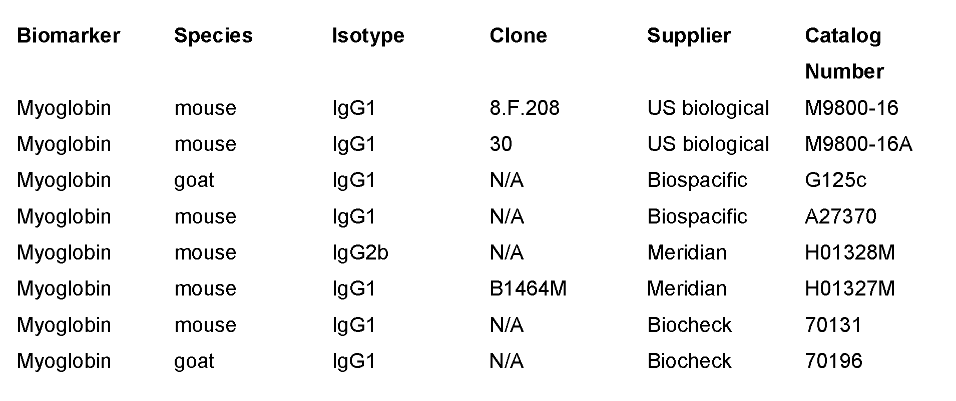


Claims
Priority Applications (8)
| Application Number | Priority Date | Filing Date | Title |
|---|---|---|---|
| AU2017335710A AU2017335710C1 (en) | 2016-09-30 | 2017-09-30 | Microfluidic device |
| US16/338,137 US11221332B2 (en) | 2016-09-30 | 2017-09-30 | Microfluidic device |
| CN201780060101.XA CN109790012B (en) | 2016-09-30 | 2017-09-30 | Microfluidic device |
| NZ751531A NZ751531A (en) | 2016-09-30 | 2017-09-30 | Microfluidic device |
| EP17855147.9A EP3519350A4 (en) | 2016-09-30 | 2017-09-30 | Microfluidic device |
| JP2019538743A JP7114602B2 (en) | 2016-09-30 | 2017-09-30 | microfluidic device |
| CA3038716A CA3038716C (en) | 2016-09-30 | 2017-09-30 | Microfluidic device |
| KR1020197012535A KR102479217B1 (en) | 2016-09-30 | 2017-09-30 | microfluidic device |
Applications Claiming Priority (2)
| Application Number | Priority Date | Filing Date | Title |
|---|---|---|---|
| US201662402087P | 2016-09-30 | 2016-09-30 | |
| US62/402,087 | 2016-09-30 |
Publications (1)
| Publication Number | Publication Date |
|---|---|
| WO2018060973A1 true WO2018060973A1 (en) | 2018-04-05 |
Family
ID=61759352
Family Applications (1)
| Application Number | Title | Priority Date | Filing Date |
|---|---|---|---|
| PCT/IB2017/056047 Ceased WO2018060973A1 (en) | 2016-09-30 | 2017-09-30 | Microfluidic device |
Country Status (10)
| Country | Link |
|---|---|
| US (1) | US11221332B2 (en) |
| EP (1) | EP3519350A4 (en) |
| JP (1) | JP7114602B2 (en) |
| KR (1) | KR102479217B1 (en) |
| CN (1) | CN109790012B (en) |
| AU (1) | AU2017335710C1 (en) |
| CA (1) | CA3038716C (en) |
| NZ (1) | NZ751531A (en) |
| SG (1) | SG10202103252VA (en) |
| WO (1) | WO2018060973A1 (en) |
Cited By (2)
| Publication number | Priority date | Publication date | Assignee | Title |
|---|---|---|---|---|
| WO2022256245A1 (en) * | 2021-06-04 | 2022-12-08 | Nutcracker Therapeutics, Inc. | Systems and methods to detect presence of fluids |
| NL2028528B1 (en) * | 2021-06-04 | 2022-12-15 | Nutcracker Therapeutics Inc | Systems and methods to detect presence of fluids |
Families Citing this family (2)
| Publication number | Priority date | Publication date | Assignee | Title |
|---|---|---|---|---|
| CA3196729A1 (en) * | 2020-11-11 | 2022-05-19 | Tural AKSEL | Affinity reagents having enhanced binding and detection characteristics |
| CN113387317B (en) * | 2021-05-27 | 2023-09-19 | 武汉理工大学 | A non-rotating axisymmetric bowl-shaped Janus micro-nano motor and its preparation method and application |
Citations (5)
| Publication number | Priority date | Publication date | Assignee | Title |
|---|---|---|---|---|
| WO2010040103A1 (en) * | 2008-10-03 | 2010-04-08 | Micronics, Inc. | Microfluidic apparatus and methods for performing blood typing and crossmatching |
| WO2010144683A2 (en) * | 2009-06-12 | 2010-12-16 | Micronics, Inc. | Compositions and methods for dehydrated storage of on-board reagents in microfluidic devices |
| WO2011094577A2 (en) * | 2010-01-29 | 2011-08-04 | Micronics, Inc. | Sample-to-answer microfluidic cartridge |
| CA2898477A1 (en) * | 2013-02-18 | 2014-08-21 | Theranos, Inc. | Systems and methods for multi-analysis |
| WO2015160863A1 (en) * | 2014-04-14 | 2015-10-22 | Sri International | Portable nucleic acid analysis systemand high-performance microfluidic electroactive polymer actuators |
Family Cites Families (12)
| Publication number | Priority date | Publication date | Assignee | Title |
|---|---|---|---|---|
| US7223363B2 (en) * | 2001-03-09 | 2007-05-29 | Biomicro Systems, Inc. | Method and system for microfluidic interfacing to arrays |
| JP2006308428A (en) * | 2005-04-28 | 2006-11-09 | Hitachi High-Technologies Corp | Nucleic acid analysis method, nucleic acid analyzer, and cartridge for nucleic acid analysis |
| US20080311585A1 (en) * | 2005-11-02 | 2008-12-18 | Affymetrix, Inc. | System and method for multiplex liquid handling |
| US7976795B2 (en) * | 2006-01-19 | 2011-07-12 | Rheonix, Inc. | Microfluidic systems |
| WO2007130549A1 (en) * | 2006-05-02 | 2007-11-15 | Govt.Of The Usa, As Represented By The Secretary, Dept. Of Health And Human Services | Monoclonal antibody microarray |
| JP4438860B2 (en) * | 2007-12-20 | 2010-03-24 | セイコーエプソン株式会社 | Biological material detection cartridge, biological material detection device, and biological material detection method |
| WO2010118427A1 (en) | 2009-04-10 | 2010-10-14 | Canon U.S. Life Sciences, Inc. | Fluid interface cartridge for a microfluidic chip |
| EP4459241A3 (en) * | 2009-12-07 | 2025-01-01 | Meso Scale Technologies, LLC. | Assay cartridge reader |
| US9731297B2 (en) * | 2011-01-06 | 2017-08-15 | Meso Scale Technologies, Llc. | Assay cartridges and methods of using the same |
| KR102090934B1 (en) * | 2012-01-09 | 2020-03-19 | 퍼킨엘머 헬스 사이언시즈, 아이엔씨. | Microfluidic reactor system |
| JP2016527494A (en) * | 2013-07-05 | 2016-09-08 | ユニバーシティ オブ ワシントン スルー イッツ センター フォー コマーシャライゼーション | Methods, compositions and systems for microfluidic assays |
| SG11201700087UA (en) | 2014-08-05 | 2017-02-27 | Sanwa Biotech Ltd | On-site diagnostic system and the method thereof |
-
2017
- 2017-09-30 SG SG10202103252VA patent/SG10202103252VA/en unknown
- 2017-09-30 CA CA3038716A patent/CA3038716C/en active Active
- 2017-09-30 AU AU2017335710A patent/AU2017335710C1/en active Active
- 2017-09-30 US US16/338,137 patent/US11221332B2/en active Active
- 2017-09-30 CN CN201780060101.XA patent/CN109790012B/en active Active
- 2017-09-30 JP JP2019538743A patent/JP7114602B2/en active Active
- 2017-09-30 NZ NZ751531A patent/NZ751531A/en unknown
- 2017-09-30 WO PCT/IB2017/056047 patent/WO2018060973A1/en not_active Ceased
- 2017-09-30 EP EP17855147.9A patent/EP3519350A4/en active Pending
- 2017-09-30 KR KR1020197012535A patent/KR102479217B1/en active Active
Patent Citations (5)
| Publication number | Priority date | Publication date | Assignee | Title |
|---|---|---|---|---|
| WO2010040103A1 (en) * | 2008-10-03 | 2010-04-08 | Micronics, Inc. | Microfluidic apparatus and methods for performing blood typing and crossmatching |
| WO2010144683A2 (en) * | 2009-06-12 | 2010-12-16 | Micronics, Inc. | Compositions and methods for dehydrated storage of on-board reagents in microfluidic devices |
| WO2011094577A2 (en) * | 2010-01-29 | 2011-08-04 | Micronics, Inc. | Sample-to-answer microfluidic cartridge |
| CA2898477A1 (en) * | 2013-02-18 | 2014-08-21 | Theranos, Inc. | Systems and methods for multi-analysis |
| WO2015160863A1 (en) * | 2014-04-14 | 2015-10-22 | Sri International | Portable nucleic acid analysis systemand high-performance microfluidic electroactive polymer actuators |
Non-Patent Citations (1)
| Title |
|---|
| See also references of EP3519350A4 * |
Cited By (2)
| Publication number | Priority date | Publication date | Assignee | Title |
|---|---|---|---|---|
| WO2022256245A1 (en) * | 2021-06-04 | 2022-12-08 | Nutcracker Therapeutics, Inc. | Systems and methods to detect presence of fluids |
| NL2028528B1 (en) * | 2021-06-04 | 2022-12-15 | Nutcracker Therapeutics Inc | Systems and methods to detect presence of fluids |
Also Published As
| Publication number | Publication date |
|---|---|
| EP3519350A1 (en) | 2019-08-07 |
| JP7114602B2 (en) | 2022-08-08 |
| CA3038716C (en) | 2024-05-21 |
| KR20190062503A (en) | 2019-06-05 |
| AU2017335710B2 (en) | 2021-12-09 |
| SG10202103252VA (en) | 2021-05-28 |
| CA3038716A1 (en) | 2018-04-05 |
| KR102479217B1 (en) | 2022-12-19 |
| AU2017335710A1 (en) | 2019-04-04 |
| AU2017335710C1 (en) | 2022-05-26 |
| US11221332B2 (en) | 2022-01-11 |
| US20190331676A1 (en) | 2019-10-31 |
| CN109790012A (en) | 2019-05-21 |
| JP2019530884A (en) | 2019-10-24 |
| EP3519350A4 (en) | 2020-05-27 |
| NZ751531A (en) | 2023-02-24 |
| CN109790012B (en) | 2023-08-11 |
Similar Documents
| Publication | Publication Date | Title |
|---|---|---|
| CA3038716C (en) | Microfluidic device | |
| JP2012127696A (en) | Analyzer and analyzing method | |
| WO2012075251A1 (en) | Sample metering device and assay device with integrated sample dilution | |
| JP7425138B2 (en) | Optical imaging system using side illumination for digital assays | |
| US8053201B2 (en) | Microfluidic control chip and method of detecting protein using the same | |
| CN106257998A (en) | For detecting the detection device of granule | |
| CN102472751B (en) | Automated lateral flow immunoassay cassette with improved flow properties | |
| Krishnamoorthy et al. | Electrokinetic label-free screening chip: a marriage of multiplexing and high throughput analysis using surface plasmon resonance imaging | |
| US9983128B2 (en) | Parallel optical examinations of a sample | |
| JP2011220768A (en) | Analyzer and analysis method | |
| CN116547537A (en) | SARS-CoV-2 antibody immunoassay | |
| KR101218178B1 (en) | Time Resolved Fluorescence Module and Immunoassay Method Using the Same | |
| RU2008130888A (en) | MAS-2VR AS A MARKER FOR DIAGNOSTICS OF STOMACH CANCER | |
| US20160169884A1 (en) | Device and method for biological analyses | |
| KR102352618B1 (en) | Test strip for immunoassay diagnosis using electric capacitance sensor | |
| CN110579589A (en) | Analytical kits for in vitro diagnostics containing blood | |
| Yoo et al. | Bead packing and release using flexible polydimethylsiloxane membrane for semi‐continuous biosensing | |
| KR20130114509A (en) | System for analyzing biological sample and method for analyzing biological sample using the system | |
| HK1174688A1 (en) | Systems and methods for determining the percentage of glycated hemoglobin |
Legal Events
| Date | Code | Title | Description |
|---|---|---|---|
| 121 | Ep: the epo has been informed by wipo that ep was designated in this application |
Ref document number: 17855147 Country of ref document: EP Kind code of ref document: A1 |
|
| ENP | Entry into the national phase |
Ref document number: 3038716 Country of ref document: CA |
|
| ENP | Entry into the national phase |
Ref document number: 2019538743 Country of ref document: JP Kind code of ref document: A |
|
| NENP | Non-entry into the national phase |
Ref country code: DE |
|
| ENP | Entry into the national phase |
Ref document number: 2017335710 Country of ref document: AU Date of ref document: 20170930 Kind code of ref document: A |
|
| ENP | Entry into the national phase |
Ref document number: 20197012535 Country of ref document: KR Kind code of ref document: A |
|
| ENP | Entry into the national phase |
Ref document number: 2017855147 Country of ref document: EP Effective date: 20190430 |