WO2018061392A1 - 内視鏡システム及びその作動方法 - Google Patents
内視鏡システム及びその作動方法 Download PDFInfo
- Publication number
- WO2018061392A1 WO2018061392A1 PCT/JP2017/024894 JP2017024894W WO2018061392A1 WO 2018061392 A1 WO2018061392 A1 WO 2018061392A1 JP 2017024894 W JP2017024894 W JP 2017024894W WO 2018061392 A1 WO2018061392 A1 WO 2018061392A1
- Authority
- WO
- WIPO (PCT)
- Prior art keywords
- light
- lens
- magnification
- image
- endoscope system
- Prior art date
- Legal status (The legal status is an assumption and is not a legal conclusion. Google has not performed a legal analysis and makes no representation as to the accuracy of the status listed.)
- Ceased
Links
Images







Classifications
-
- A—HUMAN NECESSITIES
- A61—MEDICAL OR VETERINARY SCIENCE; HYGIENE
- A61B—DIAGNOSIS; SURGERY; IDENTIFICATION
- A61B1/00—Instruments for performing medical examinations of the interior of cavities or tubes of the body by visual or photographical inspection, e.g. endoscopes; Illuminating arrangements therefor
- A61B1/00163—Optical arrangements
- A61B1/00188—Optical arrangements with focusing or zooming features
-
- A—HUMAN NECESSITIES
- A61—MEDICAL OR VETERINARY SCIENCE; HYGIENE
- A61B—DIAGNOSIS; SURGERY; IDENTIFICATION
- A61B1/00—Instruments for performing medical examinations of the interior of cavities or tubes of the body by visual or photographical inspection, e.g. endoscopes; Illuminating arrangements therefor
- A61B1/00002—Operational features of endoscopes
- A61B1/00004—Operational features of endoscopes characterised by electronic signal processing
- A61B1/00006—Operational features of endoscopes characterised by electronic signal processing of control signals
-
- A—HUMAN NECESSITIES
- A61—MEDICAL OR VETERINARY SCIENCE; HYGIENE
- A61B—DIAGNOSIS; SURGERY; IDENTIFICATION
- A61B1/00—Instruments for performing medical examinations of the interior of cavities or tubes of the body by visual or photographical inspection, e.g. endoscopes; Illuminating arrangements therefor
- A61B1/00002—Operational features of endoscopes
- A61B1/00004—Operational features of endoscopes characterised by electronic signal processing
- A61B1/00009—Operational features of endoscopes characterised by electronic signal processing of image signals during a use of endoscope
-
- A—HUMAN NECESSITIES
- A61—MEDICAL OR VETERINARY SCIENCE; HYGIENE
- A61B—DIAGNOSIS; SURGERY; IDENTIFICATION
- A61B1/00—Instruments for performing medical examinations of the interior of cavities or tubes of the body by visual or photographical inspection, e.g. endoscopes; Illuminating arrangements therefor
- A61B1/00002—Operational features of endoscopes
- A61B1/00043—Operational features of endoscopes provided with output arrangements
- A61B1/00045—Display arrangement
-
- A—HUMAN NECESSITIES
- A61—MEDICAL OR VETERINARY SCIENCE; HYGIENE
- A61B—DIAGNOSIS; SURGERY; IDENTIFICATION
- A61B1/00—Instruments for performing medical examinations of the interior of cavities or tubes of the body by visual or photographical inspection, e.g. endoscopes; Illuminating arrangements therefor
- A61B1/04—Instruments for performing medical examinations of the interior of cavities or tubes of the body by visual or photographical inspection, e.g. endoscopes; Illuminating arrangements therefor combined with photographic or television appliances
- A61B1/043—Instruments for performing medical examinations of the interior of cavities or tubes of the body by visual or photographical inspection, e.g. endoscopes; Illuminating arrangements therefor combined with photographic or television appliances for fluorescence imaging
-
- A—HUMAN NECESSITIES
- A61—MEDICAL OR VETERINARY SCIENCE; HYGIENE
- A61B—DIAGNOSIS; SURGERY; IDENTIFICATION
- A61B1/00—Instruments for performing medical examinations of the interior of cavities or tubes of the body by visual or photographical inspection, e.g. endoscopes; Illuminating arrangements therefor
- A61B1/06—Instruments for performing medical examinations of the interior of cavities or tubes of the body by visual or photographical inspection, e.g. endoscopes; Illuminating arrangements therefor with illuminating arrangements
- A61B1/0638—Instruments for performing medical examinations of the interior of cavities or tubes of the body by visual or photographical inspection, e.g. endoscopes; Illuminating arrangements therefor with illuminating arrangements providing two or more wavelengths
-
- G—PHYSICS
- G02—OPTICS
- G02B—OPTICAL ELEMENTS, SYSTEMS OR APPARATUS
- G02B23/00—Telescopes, e.g. binoculars; Periscopes; Instruments for viewing the inside of hollow bodies; Viewfinders; Optical aiming or sighting devices
- G02B23/24—Instruments or systems for viewing the inside of hollow bodies, e.g. fibrescopes
- G02B23/2407—Optical details
- G02B23/2461—Illumination
- G02B23/2469—Illumination using optical fibres
Definitions
- the present invention relates to an endoscope system that performs focusing on an observation target and an operation method thereof.
- an endoscope system including a light source device, an endoscope, and a processor device.
- the endoscope system irradiates illumination light emitted from a light source device onto an observation target via the endoscope, and a processor device based on an image signal obtained by imaging the observation target under illumination with the illumination light. An image to be observed is generated. By displaying this image on the monitor, the doctor can make a diagnosis while viewing the image on the monitor.
- a doctor When performing focusing using a zoom lens, a doctor operates the zoom operation unit to check whether the object to be observed on the monitor is in focus.
- the observation target is illuminated with a wide-band illumination light including long-wave light such as red light
- the observation target is focused on the monitor image because it reaches the deep part inside the tissue. It was difficult to check whether or not.
- the present invention provides an endoscope system capable of surely focusing even when illuminating an observation target with light including long wave light when performing focusing using a zoom lens, and an operating method thereof.
- the purpose is to provide.
- the endoscope system according to the present invention is longer than the short wave light from the first lens position of the moving lens that moves in the optical axis direction and the moving lens when the observation target illuminated by the short wave light is in focus.
- a lens driving unit that moves the moving lens to a second lens position of the moving lens that is focused on the observation target illuminated by the long wave light having the wavelength;
- the moving lens is a zoom lens for enlarging the observation target
- a first magnification when the zoom lens is at the first lens position and a second magnification when the zoom lens is at the second lens position A magnification conversion table that is stored in association with each other and a magnification conversion unit that converts the first magnification to the second magnification with reference to the magnification conversion table.
- the lens driving unit sets the zoom lens to the second magnification, It is preferable to move the lens to the second lens position.
- a position conversion table that stores a relationship between the first lens position and the second lens position; and a lens position calculation unit that obtains the second lens position from the first lens position with reference to the position conversion table. It is preferable.
- It has a light source capable of independently emitting light of a plurality of colors including violet light, blue light, or red light, short wave light is violet light or blue light, and long wave light is red among a plurality of colors of light. It is preferable to display a first image obtained by imaging an observation target that is light including light and illuminated with purple light or blue light on the display unit. Control for emitting short wave light is performed on the light source, and after moving the moving lens from the first lens position to the second lens position, control for switching from short wave light to long wave light is performed on the light source. It is preferable to have a light source control unit to perform. Control for emitting shortwave light is performed on the light source, and control for switching from shortwave light to longwave light is performed on the light source before moving the moving lens from the first lens position to the second lens position. It is preferable to have a light source control unit to perform.
- the short wave light has a first peak in the short wave band and has a spectrum having a tail on the long wave side of the short wave band, and the long wave light has a second peak on the longer wavelength side than the first peak. It is preferable to display a first image obtained by imaging an observation target illuminated with shortwave light on the display unit. It is preferable to have a light source capable of independently emitting light of a plurality of colors, and the short wave light or long wave light is multicolor light obtained by combining light of a plurality of colors.
- the short wave light or long wave light is preferably broadband light including one or a plurality of short wave narrow band light and fluorescence obtained by wavelength conversion of the short wave narrow band light by a wavelength conversion member.
- a light source that emits broadband light having a wavelength band including shortwave light and longwave light, and a first image having wavelength information corresponding to the shortwave light among images of a plurality of bands having information on an observation target illuminated with the broadband light It is preferable to have an image acquisition unit that acquires the image and a display unit that displays the first image.
- a light source that sequentially emits shortwave light and longwave light, an image acquisition unit that acquires a first image obtained by imaging an observation target illuminated by the shortwave light, and a display unit that displays the first image Is preferred. It is preferable to have an image acquisition unit that acquires a second image obtained by imaging an observation target illuminated by long wave light, and a display unit that displays the second image.
- the endoscope system according to the present invention is longer than the short wave light from the first lens position of the moving lens that moves in the optical axis direction and the moving lens when the observation target illuminated by the short wave light is in focus.
- a lens driving unit that moves the moving lens to the second lens position of the moving lens that is focused on the observation target illuminated by the long wave light of the wavelength, and the moving lens is a zoom lens that expands the observation target Referring to the magnification conversion table and the magnification conversion table for storing the first magnification when the zoom lens is at the first lens position and the second magnification when the zoom lens is at the second lens position in association with each other.
- a magnification conversion unit for converting from the first magnification to the second magnification, and the lens driving unit sets the zoom lens to the second magnification and moves the zoom lens to the second lens position.
- the present invention provides a first operation of a moving lens in a method of operating an endoscope system having a moving lens that moves in an optical axis direction when the lens driving unit is in focus on an observation target illuminated by short wave light. Moving the moving lens from the lens position to the second lens position of the moving lens that is focused on the observation object illuminated by the long wave light having a wavelength longer than that of the short wave light.
- FIG. 6 is a flowchart showing a series of flows for focusing using a zoom lens in the first embodiment. It is a block diagram which shows the function of the endoscope system of 2nd Embodiment. It is a graph which shows the spectrum of normal light of a 2nd embodiment. It is a graph which shows the spectrum of special light of a 2nd embodiment. 12 is a flowchart illustrating a series of flows for focusing using a zoom lens in the second embodiment. It is a block diagram which shows the function of the endoscope system of 3rd Embodiment. It is a top view of a rotation filter. It is a block diagram which shows the zoom control process part etc. in embodiment different from 1st Embodiment.
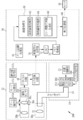
- the endoscope system 10 includes an endoscope 12, a light source device 14, a processor device 16, a monitor 18 (display unit), and a console 19.
- the endoscope 12 is optically connected to the light source device 14 and electrically connected to the processor device 16.
- the endoscope 12 has an insertion portion 12a to be inserted into the subject, an operation portion 12b provided at the proximal end portion of the insertion portion 12a, a bending portion 12c and a distal end portion 12d provided at the distal end side of the insertion portion 12a. is doing.
- the angle knob 13a of the operation portion 12b By operating the angle knob 13a of the operation portion 12b, the bending portion 12c is bent. By this bending operation, the distal end portion 12d is directed in a desired direction.
- the operation unit 12b includes a still image acquisition unit 13b used for a still image acquisition operation, a mode switching unit 13c used for an observation mode switching operation, and a zoom operation unit 13d used for a zoom magnification change operation.
- the still image acquisition unit 13b can perform a freeze operation for displaying the still image to be observed on the monitor 18 and a release operation for storing the still image in the storage.
- the endoscope system 10 has a normal mode and a special mode as observation modes.
- the observation mode is the normal mode
- the light source device 14 emits normal light obtained by combining light of a plurality of colors with the light amount ratio Lc for the normal mode, and images the observation target under illumination with the normal light. Based on the obtained image signal, a normal image is displayed on the monitor 18.
- the observation mode is the special mode
- the light source device 14 emits special light obtained by combining light of a plurality of colors with a special mode light amount ratio Ls, and images the observation target under illumination with the special light.
- a special image is displayed on the monitor 18 based on the image signal obtained in this way.
- the processor device 16 is electrically connected to the monitor 18 and the console 19.
- the monitor 18 outputs and displays an image to be observed, information attached to the image, and the like.
- the console 19 functions as a user interface that receives input operations such as designation of a region of interest (ROI: Region Of Interest) and function setting.
- ROI Region Of Interest
- the B-LED 20b emits blue light B having a wavelength band of 420 nm to 500 nm.
- the blue light B emitted from the B-LED 23 b at least a wavelength longer than the peak wavelength of 450 nm is cut by the wavelength cut filter 23.
- the blue light Bx after passing through the wavelength cut filter 23 has a wavelength range of 420 to 460 nm.
- the wavelength cut filter 23 may attenuate light in a wavelength region longer than 460 nm, instead of cutting light in a wavelength region longer than 460 nm.
- the G-LED 20c emits green light G having a wavelength band ranging from 480 nm to 600 nm.
- the R-LED 20d emits red light R with a wavelength band of 600 nm to 650 nm.
- the light emitted from each of the LEDs 20a to 20d may have the same or different center wavelength and peak wavelength.
- the light source control unit 22 adjusts the light emission timing, the light emission period, the light amount, and the spectral spectrum of the illumination light by independently controlling the lighting and extinction of the LEDs 20a to 20d and the light emission amount at the time of lighting. Control of turning on and off in the light source control unit 22 is different for each observation mode.
- the light source controller 22 turns on all the V-LEDs 20a, B-LEDs 20b, G-LEDs 20c, and R-LEDs 20d.
- the light quantity ratio Lc between the violet light V, the blue light B, the green light G, and the red light R is such that the emission amount of the blue light Bx is violet light V, green light G, and It is set to be larger than any light emission amount of the red light R.
- multicolor light for normal mode including violet light V, blue light Bx, green light G, and red light R is emitted from the light source device 14 as normal light. Since normal light has a certain intensity or more from the blue band to the red band, it is almost white.
- the light source control unit 22 turns on all of the V-LED 20a, the B-LED 20b, the G-LED 20c, and the R-LED 20d.
- the light quantity ratio Ls between the violet light V, the blue light B, the green light G, and the red light R is such that the emission amount of the violet light V is blue light Bx, green light G, and
- the red light R is set to be larger than any light emission amount, and the green light G and the red light R are set to be smaller than the purple light V and the blue light Bx.
- multicolor light for special mode including violet light V, blue light Bx, green light G, and red light R is emitted from the light source device 14 as special light.
- the special light is bluish light because the emission amount of the purple light V is large.
- special light When comparing the spectra of normal light and special light, special light has a light intensity peak such as a peak of purple light V in a short wave band such as a blue band (corresponding to the “first peak” of the present invention). And has a spectrum with a tail on the longer wavelength side than the short wave band, such as green light G and red light R.
- the normal light has a light intensity peak (corresponding to the “second peak” of the present invention) such as a blue light Bx peak in a short wave band such as a blue band, and the peak of the normal light is a special light.
- the light has a spectrum located on the longer wavelength side of the peak.
- the light source control unit 22 turns off the B-LED 20b, the G-LED 20c, and the R-LED 20d for a certain period of time, and the V-LED 20a Control to turn on only.
- the purple light V emitted from the V-LED 20a is used for focusing the observation target.
- the light source control unit 22 turns on all the V-LEDs 20a, B-LEDs 20b, G-LEDs 20c, and R-LEDs 20d again after a predetermined time and emits normal light or special light.
- the illumination light emitted from the light source 20 enters a light guide 24 inserted into the insertion portion 12a through an optical path coupling portion (not shown) formed by a mirror, a lens, or the like.
- the light guide 24 is built in the endoscope 12 and the universal cord, and propagates the illumination light to the distal end portion 12 d of the endoscope 12.
- the universal cord is a cord that connects the endoscope 12 to the light source device 14 and the processor device 16.
- a multimode fiber can be used as the light guide 24.
- a thin fiber cable having a core diameter of 105 ⁇ m, a cladding diameter of 125 ⁇ m, and a diameter including a protective layer serving as an outer cover of ⁇ 0.3 mm to ⁇ 0.5 mm can be used.
- the distal end portion 12d of the endoscope 12 is provided with an illumination optical system 30a and an imaging optical system 30b.
- the illumination optical system 30 a has an illumination lens 32. Through this illumination lens 32, the observation target is illuminated with illumination light propagated through the light guide 24.
- the imaging optical system 30 b includes an objective lens 34, a magnifying optical system 36, and an imaging sensor 38. Through the objective lens 34 and the magnifying optical system 36, various kinds of light such as reflected light, scattered light, and fluorescence from the observation object enter the image sensor 38. As a result, an image to be observed is formed on the image sensor 38.
- the imaging sensor 38 images the observation target illuminated with normal light, thereby outputting a Bc image signal from the B pixel, outputting a Gc image signal from the G pixel, and outputting an Rc image signal from the R pixel. Is output.
- the imaging sensor 38 images the observation target illuminated with the special light, thereby outputting a Bs image signal from the B pixel, outputting a Gs image signal from the G pixel, and outputting from the R pixel to Rs. Output image signal.
- the B pixel image signal is output from the B pixel by imaging the observation target illuminated by the violet light V.
- the Gp image signal is output from the G pixel
- the Rp image signal is output from the R pixel.
- the CDS / AGC circuit 40 performs correlated double sampling (CDS: Correlated Double Sampling) and automatic gain control (AGC: Automatic Gain Control) on the analog image signal received from the image sensor 38.
- the A / D (Analog-to-Digital) conversion circuit 42 converts the analog image signal that has passed through the CDS / AGC circuit 40 into a digital image signal.
- the A / D conversion circuit 42 inputs the digital image signal after A / D conversion to the processor device 16.
- the processor device 16 includes an image signal acquisition unit 50, a DSP (Digital Signal Processor) 52, a noise reduction unit 54, an image processing unit 58, a display control unit 60, and a zoom control processing unit 61.
- the hardware structure of each unit such as the image signal acquisition unit 50, the noise reduction unit 54, the image processing unit 58, the display control unit 60, and the zoom control processing unit 61 is the following various processors. .
- the circuit configuration is changed after the manufacture of CPU (Central Processing Unit) and FPGA (Field Programmable Gate Array), which are general-purpose processors that function as various processing units by executing software (programs).
- the image signal acquisition unit 50 acquires a digital image signal corresponding to the observation mode from the endoscope 12.
- Bc image signals, Gc image signals, and Rc image signals are acquired as normal images.
- Bs image signals, Gs image signals, and Rs image signals are acquired as special images.
- a Bp image signal, a Gp image signal, and an Rp image signal are acquired.
- Linear matrix processing enhances the color reproducibility of gain-corrected image signals.
- the gamma conversion process adjusts the brightness and saturation of the image signal subjected to the linear matrix process.
- the image signal subjected to the gamma conversion process is subjected to a demosaic process (also referred to as an isotropic process or a synchronization process), thereby generating a signal of an insufficient color in each pixel by interpolation.
- demosaic processing all the pixels have RGB signals.
- the noise reduction unit 54 performs noise reduction processing by, for example, a moving average method or a median filter method on the image signal subjected to demosaic processing or the like in the DSP 52 to reduce noise.
- Special image processing unit 64 operates when the special mode is set.
- the special image processing unit 64 performs color conversion processing, color enhancement processing, and structure enhancement processing on the received special image.
- the contents of the color conversion process, the color enhancement process, and the structure enhancement process are the same as those of the normal image processing unit 62.
- the special image is obtained based on the special mode illumination light in which the violet light V, which has a high absorption coefficient of hemoglobin in the blood vessel, has a larger light emission amount than the blue light Bx, green light G, and red light R of other colors. Since this is an image, the resolution of the blood vessel structure is higher than that of other structures.
- the special image is input to the display control unit 60 as it is when the special mode is set.
- the focus adjustment image generation unit 66 operates during zoom operation in the normal mode and the special mode.
- the focus adjustment image generation unit 66 generates a focus adjustment image for focusing on the observation target based on the Bp image signal.
- the generated focus adjustment image is input to the display control unit 60. Details of the focus adjustment image generation unit 66 will be described later.
- the display control unit 60 performs display control for displaying an image on the monitor 18 from the image processing unit 58.
- the display control unit 60 performs control to display a normal image on the monitor 18.
- the display control unit 60 performs control to display the special image on the monitor 18.
- the display control unit 60 performs control to display the focus adjustment image on the monitor 18 under a certain condition during zoom operation.
- the zoom control processing unit 61 controls the entire endoscope 12, the light source device 14, and the processor device 16 when the zoom operation unit 13d is operated.
- the zoom control processing unit 61 instructs the light source control unit 22 to emit only the violet light V (corresponding to “shortwave light” of the present invention).
- the purple light V is illuminated on the observation target.
- the imaging sensor 38 outputs a Bp image signal, a Gp image signal, and an Rp image signal by imaging the observation target illuminated by the purple light V.
- the focus adjustment image generation unit 66 generates a focus adjustment image (corresponding to the “first image” of the present invention) based on the Bp image signal among the image signals output from the image sensor 38.
- the generated focus adjustment image is displayed on the monitor 18 by the display control unit 60. While observing the focus adjustment image, the user operates the zoom operation unit 13d so that the observation target has a target size.
- the focus adjustment image Pa is generated from the Bp image signal obtained from the violet light V in the wavelength region where the absorption coefficient of the hemoglobin of the blood vessel is high, and therefore the edge of the blood vessel structure Vs or the like. The structure is displayed in high resolution.
- the focus adjustment image is a monochrome image
- the focus adjustment image may be displayed in parallel with the normal image acquired before the operation of the zoom operation unit 13d to facilitate focusing.
- the gradation balance is changed in a plurality of stages, for example, three stages, and a color focus adjustment image in which each stage image is assigned to each RGB channel is displayed on the monitor 18. You may make it do.
- the zoom operation unit 13d so that the edges in the focus adjustment image are clearly and clearly displayed. Then, when the edge is clearly displayed and the zoom lens 36a reaches the first lens position, the operation of the zoom operation unit 13d is stopped.
- the zoom operation unit 13d is not operated for a predetermined time or longer, it is considered that the object to be observed is in focus, and the magnification of the zoom lens 36a at this time is transmitted to the zoom control processing unit 61 as the first magnification. Is done.
- the zoom control processing unit 61 adjusts the first magnification of the zoom lens 36a when the observation target illuminated with the purple light V is in focus to the observation target illuminated with normal light or special light.
- a magnification conversion unit 70 for converting to 2 magnifications is provided.
- the magnification conversion unit 70 performs conversion from the first magnification to the second magnification using the magnification conversion table 72.
- the magnification conversion table 72 enlarges the observation target with the same magnification as the first magnification and focuses on the observation target illuminated with normal light. Is associated with the second magnification for normal light.
- Such a table is stored in a recording medium such as a hard disk (not shown) or an SSD (Solid State Drive).
- magnification conversion table 72 is used for special light for focusing on the observation target illuminated with special light while expanding the observation target with the same size as the first magnification and the first magnification.
- the second magnification is stored in association with the second magnification.
- the second magnification for normal light is different from the second magnification for special light because the ratio of long-wave light such as red light R is different between normal light and special light. This is because, due to the difference in the ratio of long wave light, the position where the observation target is focused when illuminated with normal light is different from the position where the observation target is focused.
- the magnification conversion table 72 may be provided for each part such as the esophagus, stomach, and large intestine. In this case, it is preferable to set the type of the site to be observed manually using a console or the like, or by automatic determination based on an image.
- the first magnification and the second magnification for normal light are associated with each other and stored in the magnification conversion table 72.
- a series of methods are performed by changing the magnification of the zoom lens 36a.
- a table for illuminating normal light is created, a table is created for special light in the same manner.
- the table may be created by simulation calculation based on modeling expressing a light scattering coefficient in a human tissue.
- the observation target is illuminated with the purple light V in order to generate the focus adjustment image.
- the observation target is illuminated with the blue light Bx. It may be.
- all the four colors of light of purple light V, blue light Bx, green light G, and red light R are illuminated, and normal light or special light that is different by the light amount ratio is emitted.
- multicolor light including at least long wave light such as red light R may be emitted.
- the first magnification and the second magnification for multicolor light are associated and stored in the magnification conversion table 72 in order to focus on the observation object illuminated with the multicolor light.
- the observation target is illuminated using a laser light source and a phosphor instead of the four-color LEDs 20a to 20d shown in the first embodiment.
- a laser light source and a phosphor instead of the four-color LEDs 20a to 20d shown in the first embodiment.
- a blue laser that emits blue laser light having a central wavelength of 445 ⁇ 10 nm, instead of the four color LEDs 20a to 20d, in the light source 20 of the light source device 14.
- a light source (denoted as “445LD”; LD represents “Laser Diode”) 104 and a blue-violet laser light source (denoted as “405LD”) 106 that emits a blue-violet laser beam having a center wavelength of 405 ⁇ 10 nm are provided. .
- Light emission from the semiconductor light emitting elements of these light sources 104 and 106 is individually controlled by the light source control unit 108, and the light quantity ratio between the emitted light of the blue laser light source 104 and the emitted light of the blue-violet laser light source 106 is freely changeable. It has become.
- the half-value width of the blue laser beam or the blue-violet laser beam is preferably about ⁇ 10 nm.
- a broad area type InGaN laser diode can be used, and an InGaNAs laser diode or a GaNAs laser diode can also be used.
- a light-emitting body such as a light-emitting diode may be used as the light source.
- both the blue-violet laser beam (corresponding to the “short-wave narrow-band light” of the present invention) and the blue laser beam are incident on the phosphor 110, so that the blue-violet laser beam as shown in FIG.
- the broadband light for the special mode which combines the laser light, the blue laser light, and the fluorescence excited and emitted from the phosphor 110 by the blue laser light, is illuminated as the special light on the observation target.
- a special image including a Bs image signal, a Gs image signal, and an Rs image signal is obtained.
- the phosphor 110 absorbs a part of the blue laser light and emits a plurality of types of phosphors that excite and emit green to yellow (for example, a phosphor such as YAG phosphor or BAM (BaMgAl 10 O 17 )). It is preferable to use what is comprised including. If a semiconductor light emitting element is used as an excitation light source for the phosphor 110 as in this configuration example, high intensity white light can be obtained with high luminous efficiency, and the intensity of white light can be easily adjusted, and the color of white light can be easily adjusted. Changes in temperature and chromaticity can be kept small.
- the magnification conversion unit 70 converts the first magnification of the zoom lens 36a to a second magnification for focusing on the observation target illuminated with normal light or special light.
- the lens driving unit 36b changes the magnification of the zoom lens 36a from the first magnification to the second magnification.
- the observation object is illuminated with normal light or special light, and the observation object illuminated with the normal light or special light is imaged. Thereby, a normal image or a special image in which the object to be observed is in focus is obtained.
- a normal image or a special image is displayed on the monitor 18.
- the observation target is illuminated using a white light source such as a xenon lamp and a rotation filter instead of the four-color LEDs 20a to 20d. Further, instead of the color imaging sensor 38, the observation target may be imaged by a monochrome imaging sensor. In the following, only portions different from the first embodiment will be described, and description of portions that are substantially the same as those of the first embodiment will be omitted.
- the white light source 202 is a xenon lamp, a white LED, or the like, and emits white light having a wavelength range from blue to red.
- the rotary filter 204 includes a normal mode filter 210 provided on the inner side closest to the rotation axis, and a special mode filter 212 provided on the outer side of the normal mode filter 210 (see FIG. 15).
- the filter switching unit 206 moves the rotary filter 204 in the radial direction. Specifically, the filter switching unit 206 inserts the normal mode filter 210 into the optical path of white light when the mode switching unit 13c sets the normal mode. The filter switching unit 206 inserts the special mode filter 212 into the optical path of white light when the special mode is set.
- the normal mode filter 210 is provided with a Bb filter 210a, a G filter 210b, and an R filter 210c along the circumferential direction.
- the Bb filter 210a transmits broadband blue light Bb having a wavelength range of 400 to 500 nm of white light.
- the G filter 210b transmits green light G out of white light.
- the R filter 210c transmits red light R out of white light.
- the broadband blue light Bb corresponding to the “short wave light” of the present invention
- the green light G, and the red light R (the “long light” of the present invention) as the normal light.
- the rotation filter 204 is similarly driven even when the zoom operation unit 13d is operated in the normal mode. The same applies to the special mode.
- the special mode filter 212 is provided with a Bn filter 212a and a Gn filter 212b along the circumferential direction.
- the Bn filter 212a transmits blue narrow band light Bn of 400 to 450 nm out of white light.
- the Gn filter 212b transmits green narrowband light Gn of 530 to 570 nm out of white light. Therefore, in the special mode, the rotating filter 204 rotates, and as the special light, blue narrow band light (corresponding to “short wave light” of the present invention) and green narrow band light (corresponding to “long wave light” of the present invention). Are irradiated sequentially toward the observation target.
- the observation target is imaged by the monochrome imaging sensor 208 every time the observation target is illuminated with broadband blue light Bb, green light G, and red light R.
- a Bc image signal is obtained when the broadband blue light Bb is illuminated
- a Gc image signal is obtained when the green light G is illuminated
- an Rc image signal is obtained when the red light R is illuminated.
- the observation target is imaged by the monochrome imaging sensor 208 every time the observation target is illuminated with the blue narrow band light Bn and the green narrow band light Gn.
- a Bn image signal is obtained when the blue narrow-band light Bn is illuminated
- a Gn image signal is obtained when the green narrow-band light Gn is irradiated.
- a series of flows for focusing on the observation target using the zoom lens are as follows. This is different from the first embodiment. Since a series of flows in the third embodiment is the same as that of the second embodiment, description thereof is omitted (see FIG. 13).
- the zoom lens for enlarging the observation target is used.
- the present invention can be implemented as long as it is a moving lens that moves in the optical axis direction.
- the zoom lens 36a is changed from the first magnification to the second magnification, so that the position of the zoom lens 36a is focused on the observation object illuminated by the purple light V.
- the zoom lens 36a is moved to the second lens position that is in focus with the observation object illuminated with normal light or special light.
- the position of the zoom lens 36a may be changed by other methods.
- the zoom control processing unit 61 includes a position conversion table 80 that stores in advance the relationship between the first lens position and the second lens position, and a lens position calculation unit 82, and zooms.
- a method for changing the position of the lens 36a will be described below.
- the lens position calculation unit 82 refers to the position conversion table 80 and obtains the second lens position that focuses on the observation target illuminated with normal light or special light from the first lens position.
- the lens driving unit 36b moves the position of the zoom lens 36a from the first lens position to the second lens position.
- the special mode when a normal image is displayed on the monitor 18 in the normal mode, when the zoom operation is performed, the special mode is temporarily switched to the special mode. May be displayed on the monitor 18 as a focus adjustment image.
- the special image displays an edge structure such as a blood vessel structure with high resolution. Therefore, the special image is also an image suitable for focusing the observation target.
- the normal mode is switched again and the normal image is displayed on the monitor 18.
Landscapes
- Health & Medical Sciences (AREA)
- Life Sciences & Earth Sciences (AREA)
- Surgery (AREA)
- Physics & Mathematics (AREA)
- Engineering & Computer Science (AREA)
- Optics & Photonics (AREA)
- Biomedical Technology (AREA)
- General Health & Medical Sciences (AREA)
- Pathology (AREA)
- Nuclear Medicine, Radiotherapy & Molecular Imaging (AREA)
- Biophysics (AREA)
- Heart & Thoracic Surgery (AREA)
- Medical Informatics (AREA)
- Molecular Biology (AREA)
- Animal Behavior & Ethology (AREA)
- Radiology & Medical Imaging (AREA)
- Public Health (AREA)
- Veterinary Medicine (AREA)
- Signal Processing (AREA)
- Astronomy & Astrophysics (AREA)
- General Physics & Mathematics (AREA)
- Endoscopes (AREA)
- Instruments For Viewing The Inside Of Hollow Bodies (AREA)
Abstract
長波光を含む光を観察対象に照明する場合であっても、確実にピント合わせをすることができる内視鏡システム及びその作動方法を提供する。移動レンズは、光軸方向に移動する。レンズ駆動部は、短波光で照明された観察対象にピントが合っている場合における移動レンズの第1のレンズ位置から、短波光よりも長波長の長波光で照明された観察対象にピントが合う移動レンズの第2のレンズ位置に、移動レンズを移動させる。
Description
本発明は、観察対象に対してピント合わせを行う内視鏡システム及びその作動方法に関する。
医療分野においては、光源装置、内視鏡、及びプロセッサ装置を備える内視鏡システムを用いた診断が広く行われている。内視鏡システムは、光源装置が発する照明光を、内視鏡を介して観察対象に照射し、その照明光により照明中の観察対象を撮像して得た画像信号に基づいて、プロセッサ装置が観察対象の画像を生成する。この画像をモニタに表示することにより、医師は、モニタ上の画像を見ながら診断を行うことができる。
医師による診断の際には、撮像センサが設けられた内視鏡の先端部を、体内への挿入方向に沿って移動させるとともに、また、状況に応じて、観察対象に近づけたり離したりすることがある。このように内視鏡の先端部が動くことにより、観察対象との距離が変化し、観察対象にピントが合わなくなって、画像が見にくくなることがある。また、ズームレンズにより観察対象を拡大した場合にも、観察対象にピントが合わなくなることがある。このような問題に対して、特許文献1では、内視鏡にオートフォーカス機能を加えることにより、観察対象に自動でピントが合うようにしている。
特許文献1のように、内視鏡にオートフォーカス機能を追加する場合には、内視鏡の先端部にフォーカスレンズとそれを駆動する駆動部を加える必要がある。そのため、オートフォーカス機能の追加は、内視鏡先端部のコンパクト化を妨げることになる。したがって、現在においては、ズームレンズを使って、また、先端部の位置を微調整することによって、観察対象にピントを合わせることが一般的である。
ズームレンズを用いてピント合わせを行う場合には、医師が、ズーム操作部を操作して、モニタ上の観察対象にピントが合っているかどうかを確認している。しかしながら、赤色光のような長波光を含む広い帯域の照明光により観察対象を照明した場合には、組織内部の深い部分にまで深達するため、モニタの画像上において、観察対象にピントが合っているかどうかを確認しにくいことがあった。
本発明は、ズームレンズを用いてピント合わせを行う場合において、長波光を含む光を観察対象に照明する場合であっても、確実にピント合わせをすることができる内視鏡システム及びその作動方法を提供することを目的とする。
本発明の内視鏡システムは、光軸方向に移動する移動レンズと、短波光により照明された観察対象にピントが合っている場合における移動レンズの第1のレンズ位置から、短波光よりも長波長の長波光により照明された観察対象にピントが合う移動レンズの第2のレンズ位置に、移動レンズを移動させるレンズ駆動部とを備える。
移動レンズが、観察対象を拡大するズームレンズである場合において、ズームレンズが第1のレンズ位置のある場合の第1倍率と、ズームレンズが第2のレンズ位置にある場合の第2倍率とを関連付けて記憶する倍率変換テーブルと、倍率変換テーブルを参照して、第1倍率から第2倍率に変換する倍率変換部とを有し、レンズ駆動部は、ズームレンズを第2倍率にして、第2のレンズ位置に移動させることが好ましい。第1のレンズ位置と第2のレンズ位置との関係を記憶する位置変換テーブルと、位置変換テーブルを参照して、第1のレンズ位置から第2のレンズ位置を求めるレンズ位置算出部とを有することが好ましい。
紫色光、青色光、又は赤色光を含む複数色の光を独立して発光可能な光源を有し、短波光は、紫色光又は青色光であり、長波光は、複数色の光のうち赤色光を含む光であり、紫色光又は青色光で照明された観察対象を撮像して得られる第1画像を表示部に表示することが好ましい。短波光を発光するための制御を、光源に対して行い、第1のレンズ位置から第2のレンズ位置に移動レンズを移動させた後に、短波光から長波光に切り替える制御を、光源に対して行う光源制御部を有することが好ましい。短波光を発光するための制御を、光源に対して行い、第1のレンズ位置から第2のレンズ位置に移動レンズを移動させる前に、短波光から長波光に切り替える制御を、光源に対して行う光源制御部を有することが好ましい。
短波光は、短波帯域に第1のピークを持ち、且つ短波帯域よりも長波側に裾を持つスペクトルを有する光であり、長波光は、第1のピークよりも長波長側に第2のピークを持つ光であり、短波光で照明された観察対象を撮像して得られる第1画像を表示部に表示することが好ましい。複数色の光を独立して発光可能な光源を有し、短波光又は長波光は、複数色の光を組み合わせて得られる多色光であることが好ましい。短波光又は長波光は、1又は複数の短波の狭帯域光と、短波の狭帯域光を波長変換部材により波長変換して得られる蛍光とを含む広帯域光であることが好ましい。
短波光及び長波光を含む波長帯域を有する広帯域光を発光する光源と、広帯域光で照明された観察対象の情報を有する複数帯域の画像のうち、短波光に対応する波長情報を有する第1画像を取得する画像取得部と、第1画像を表示する表示部とを有することが好ましい。短波光と長波光とを順次発光する光源と、短波光により照明された観察対象を撮像して得られる第1画像を取得する画像取得部と、第1画像を表示する表示部とを有することが好ましい。長波光により照明された観察対象を撮像して得られる第2画像を取得する画像取得部と、第2画像を表示する表示部を有することが好ましい。
本発明の内視鏡システムは、光軸方向に移動する移動レンズと、短波光により照明された観察対象にピントが合っている場合における移動レンズの第1のレンズ位置から、短波光よりも長波長の長波光により照明された観察対象にピントが合う移動レンズの第2のレンズ位置に移動レンズを移動させるレンズ駆動部とを備え、移動レンズが、観察対象を拡大するズームレンズである場合において、ズームレンズが第1のレンズ位置のある場合の第1倍率と、ズームレンズが第2のレンズ位置にある場合の第2倍率とを関連付けて記憶する倍率変換テーブルと、倍率変換テーブルを参照して、第1倍率から第2倍率に変換する倍率変換部とを有し、レンズ駆動部は、ズームレンズを第2倍率にして、第2のレンズ位置に移動させる。
本発明は、光軸方向に移動する移動レンズを有する内視鏡システムの作動方法において、レンズ駆動部が、短波光により照明された観察対象にピントが合っている場合における移動レンズの第1のレンズ位置から、短波光よりも長波長の長波光により照明された観察対象にピントが合う移動レンズの第2のレンズ位置に、移動レンズを移動させるステップとを有する。
本発明によれば、長波光を含む光を観察対象に照明する場合であっても、確実にピント合わせをすることができる。
[第1実施形態]
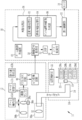
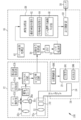
図1に示すように、内視鏡システム10は、内視鏡12と、光源装置14と、プロセッサ装置16と、モニタ18(表示部)と、コンソール19とを有する。内視鏡12は、光源装置14と光学的に接続し、かつ、プロセッサ装置16と電気的に接続する。内視鏡12は、被検体内に挿入する挿入部12aと、挿入部12aの基端部分に設けた操作部12bと、挿入部12aの先端側に設けた湾曲部12c及び先端部12dを有している。操作部12bのアングルノブ13aを操作することにより、湾曲部12cが湾曲動作する。この湾曲動作によって、先端部12dを所望の方向に向ける。
図1に示すように、内視鏡システム10は、内視鏡12と、光源装置14と、プロセッサ装置16と、モニタ18(表示部)と、コンソール19とを有する。内視鏡12は、光源装置14と光学的に接続し、かつ、プロセッサ装置16と電気的に接続する。内視鏡12は、被検体内に挿入する挿入部12aと、挿入部12aの基端部分に設けた操作部12bと、挿入部12aの先端側に設けた湾曲部12c及び先端部12dを有している。操作部12bのアングルノブ13aを操作することにより、湾曲部12cが湾曲動作する。この湾曲動作によって、先端部12dを所望の方向に向ける。
また、操作部12bには、アングルノブ13aの他、静止画像の取得操作に用いる静止画像取得部13b、観察モードの切り替え操作に用いるモード切替部13c、ズーム倍率の変更操作に用いるズーム操作部13dを設けている。静止画像取得部13bは、モニタ18に観察対象の静止画像を表示するフリーズ操作と、ストレージに静止画像を保存するレリーズ操作が可能である。
内視鏡システム10は、観察モードとして、通常モードと、特殊モードとを有している。観察モードが通常モードである場合、光源装置14は、複数色の光を通常モード用の光量比Lcで合波した通常光を発光するとともに、この通常光で照明中の観察対象を撮像して得られた画像信号に基づき、通常画像をモニタ18に表示する。また、光源装置14は、観察モードが特殊モードである場合、複数色の光を特殊モード用の光量比Lsで合波した特殊光を発光するとともに、この特殊光で照明中の観察対象を撮像して得られた画像信号に基づき、特殊画像をモニタ18に表示する。
プロセッサ装置16は、モニタ18及びコンソール19と電気的に接続する。モニタ18は、観察対象の画像や、画像に付帯する情報等を出力表示する。コンソール19は、関心領域(ROI : Region Of Interest)の指定等や機能設定等の入力操作を受け付けるユーザインタフェースとして機能する。
図2に示すように、光源装置14は、観察対象の照明に用いる照明光を発する光源20と、光源20を制御する光源制御部22とを備えている。光源20は、複数色のLED(Light Emitting Diode)等の半導体光源である。光源制御部22は、LED等のオン/オフや、LED等の駆動電流や駆動電圧の調整によって、照明光の発光量を制御する。また、光源制御部22は、光学フィルタの変更等によって、照明光の波長帯域を制御する。
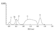
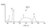
第1実施形態では、光源20は、V-LED(Violet Light Emitting Diode)20a、B-LED(Blue Light Emitting Diode)20b、G-LED(Green Light Emitting Diode)20c、及びR-LED(Red Light Emitting Diode)20dの4色のLEDと、波長カットフィルタ23とを有している。図3に示すように、V-LED20aは、波長帯域380nm~420nmの紫色光Vを発する。
B-LED20bは、波長帯域420nm~500nmの青色光Bを発する。B-LED23bから出射した青色光Bのうち少なくともピーク波長の450nmよりも長波長側は、波長カットフィルタ23によりカットされる。これにより、波長カットフィルタ23を透過した後の青色光Bxは、420~460nmの波長範囲になる。このように、460nmよりも長波長側の波長域の光をカットしているのは、この460nmよりも長波長側の波長域の光は、観察対象である血管の血管コントラストを低下させる要因であるためである。なお、波長カットフィルタ23は、460nmよりも長波長側の波長域の光をカットする代わりに、460nmよりも長波長側の波長域の光を減光させてもよい。
G-LED20cは、波長帯域が480nm~600nmに及ぶ緑色光Gを発する。R-LED20dは、波長帯域が600nm~650nmに及び赤色光Rを発する。なお、各LED20a~20dから発せられる光は、それぞれの中心波長とピーク波長とが同じであっても良いし、異なっていても良い。
光源制御部22は、各LED20a~20dの点灯や消灯、及び点灯時の発光量等を独立に制御することによって、照明光の発光タイミング、発光期間、光量、及び分光スペクトルの調節を行う。光源制御部22における点灯及び消灯の制御は、観察モードごとに異なっている。
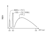
通常モードの場合、光源制御部22は、V-LED20a、B-LED20b、G-LED20c、及びR-LED20dを全て点灯させる。その際、図4に示すように、紫色光V、青色光B、緑色光G、及び赤色光R間の光量比Lcは、青色光Bxの発光量が、紫色光V、緑色光G、及び赤色光Rのいずれの発光量よりも大きくなるように、設定されている。これにより、通常モードでは、光源装置14から、紫色光V、青色光Bx、緑色光G、及び赤色光Rを含む通常モード用の多色光が、通常光として、が発せられる。通常光は、青色帯域から赤色帯域まで一定以上の強度を有しているため、ほぼ白色となっている。
特殊モードの場合についても、光源制御部22は、V-LED20a、B-LED20b、G-LED20c、及びR-LED20dを全て点灯させる。その際、図5に示すように、紫色光V、青色光B、緑色光G、及び赤色光R間の光量比Lsは、紫色光Vの発光量が、青色光Bx、緑色光G、及び赤色光Rのいずれの発光量よりも大きくなるように、また、緑色光G及び赤色光Rは紫色光V及び青色光Bxよりも小さくなるように、設定されている。これにより、特殊モードでは、光源装置14から、紫色光V、青色光Bx、緑色光G、及び赤色光Rを含む特殊モード用の多色光が、特殊光として発せられる。特殊光は、紫色光Vの発光量が大きいことから、青みを帯びた光となっている。
なお、通常光と特殊光のスペクトルをそれぞれ比較すると、特殊光は、青色帯域などの短波帯域に、紫色光Vのピークなど光強度のピーク(本発明の「第1のピーク」に対応する)を持ち、且つ緑色光Gや赤色光Rなど短波帯域よりも長波長側に裾を持つスペクトルを有する光となっている。一方、通常光は、青色帯域など短波帯域に、青色光Bxのピークなど光強度のピーク(本発明の「第2のピーク」に対応する)を有し、且つこの通常光のピークは特殊光のピークよりも長波長側にあるスペクトルを有する光となっている。
通常モード及び特殊モードのいずれにおいても、ズーム操作部13dを操作したときには、光源制御部22は、一定時間の間だけ、B-LED20b、G-LED20c、R-LED20dを消灯して、V-LED20aのみを点灯させる制御を行う。このV-LED20aから発せられる紫色光Vは、観察対象のピント合わせに用いられる。光源制御部22は、一定時間の経過後は、再び、全てのV-LED20a、B-LED20b、G-LED20c、R-LED20dを点灯して、通常光又は特殊光を発光する。
図2に示すように、光源20が発した照明光は、ミラーやレンズ等により形成される光路結合部(図示しない)を介して、挿入部12a内に挿通したライトガイド24に入射する。ライトガイド24は、内視鏡12及びユニバーサルコードに内蔵しており、照明光を内視鏡12の先端部12dまで伝搬する。ユニバーサルコードは、内視鏡12と光源装置14及びプロセッサ装置16とを接続するコードである。なお、ライトガイド24としては、マルチモードファイバを使用することができる。一例として、ライトガイド24には、コア径105μm、クラッド径125μm、外皮となる保護層を含めた径がφ0.3mm~φ0.5mmの細径なファイバケーブルを使用することができる。
内視鏡12の先端部12dには、照明光学系30aと撮像光学系30bとを設けている。照明光学系30aは、照明レンズ32を有している。この照明レンズ32を介して、ライトガイド24を伝搬した照明光によって観察対象を照明する。撮像光学系30bは、対物レンズ34と、拡大光学系36と、撮像センサ38とを有している。これら対物レンズ34及び拡大光学系36を介して、観察対象からの反射光、散乱光、及び蛍光等の各種の光が撮像センサ38に入射する。これにより、撮像センサ38に観察対象の像が結像する。
拡大光学系36は、観察対象を拡大するズームレンズ36aと、ズームレンズ36aを光軸方向CLに移動させるレンズ駆動部36bとを備えている。ズームレンズ36aは、レンズ駆動部36bによるズーム制御に従って、テレ端とワイド端の間で自在に移動させることにより、撮像センサ38に結像する観察対象を拡大又は縮小させる。また、ズームレンズ36aは、通常光又は特殊光により照明された観察対象に対するピント合わせにも用いられる。このズームレンズ36aを用いるピント合わせの詳細については、後述する。
撮像センサ38は、照明光が照射された観察対象を撮像するカラー撮像センサである。撮像センサ38の各画素には、R(赤色)カラーフィルタ、G(緑色)カラーフィルタ、B(青色)カラーフィルタのいずれかを設けている。撮像センサ38は、Bカラーフィルタが設けられているB画素により紫色から青色の光を受光し、Gカラーフィルタが設けられているG画素により緑色の光を受光し、Rカラーフィルタが設けられているR画素により赤色の光を受光する。そして、各色の画素から、RGB各色の画像信号を出力する。撮像センサ38は、出力した画像信号を、CDS/AGC回路40に送信する。
通常モードにおいては、撮像センサ38は、通常光が照明された観察対象を撮像することにより、B画素からBc画像信号を出力し、G画素からGc画像信号を出力し、R画素からRc画像信号を出力する。また、特殊モードにおいては、撮像センサ38は、特殊光が照明された観察対象を撮像することにより、B画素からBs画像信号を出力し、G画素からGs画像信号を出力し、R画素からRs画像信号を出力する。また、通常モード及び特殊モードにおいて、ズーム作動中に紫色光Vが観察対象に照明された場合には、紫色光Vにより照明された観察対象を撮像することにより、B画素からBp画像信号を出力し、G画素からGp画像信号を出力し、R画素からRp画像信号を出力する。
撮像センサ38としては、CCD(Charge Coupled Device)撮像センサやCMOS(Complementary Metal-Oxide Semiconductor)撮像センサ等を利用可能である。また、RGBの原色のカラーフィルタを設けた撮像センサ38の代わりに、C(シアン)、M(マゼンタ)、Y(イエロー)及びG(緑)の補色フィルタを備えた補色撮像センサを用いても良い。補色撮像センサを用いる場合には、CMYGの4色の画像信号を出力する。このため、補色-原色色変換によって、CMYGの4色の画像信号をRGBの3色の画像信号に変換することにより、撮像センサ38と同様のRGB各色の画像信号を得ることができる。また、撮像センサ38の代わりに、カラーフィルタを設けていないモノクロセンサを用いても良い。
CDS/AGC回路40は、撮像センサ38から受信したアナログの画像信号に、相関二重サンプリング(CDS:Correlated Double Sampling)や自動利得制御(AGC:Automatic Gain Control)を行う。A/D(Analog to Digital)変換回路42は、CDS/AGC回路40を経たアナログ画像信号を、デジタルの画像信号に変換する。A/D変換回路42は、A/D変換後のデジタル画像信号を、プロセッサ装置16に入力する。
プロセッサ装置16は、画像信号取得部50と、DSP(Digital Signal Processor)52と、ノイズ低減部54と、画像処理部58と、表示制御部60と、ズーム制御処理部61とを備えている。画像信号取得部50と、ノイズ低減部54と、画像処理部58と、表示制御部60と、ズーム制御処理部61といった各部のハードウェア的な構造は、次に示すような各種のプロセッサである。各種のプロセッサには、ソフトウエア(プログラム)を実行して各種の処理部として機能する汎用的なプロセッサであるCPU(Central Processing Unit)、FPGA (Field Programmable Gate Array) などの製造後に回路構成を変更可能なプロセッサであるプログラマブルロジックデバイス(Programmable Logic Device:PLD)、ASIC(Application Specific Integrated Circuit)などの特定の処理を実行させるために専用に設計された回路構成を有するプロセッサである専用電気回路などが含まれる。なお、内視鏡12や光源装置14の内部の各部についても同様である。
画像信号取得部50(本発明の「画像取得部」に相当する)は、内視鏡12から、観察モードに対応したデジタル画像信号を取得する。通常モードの場合には、通常画像として、Bc画像信号、Gc画像信号、Rc画像信号を取得する。特殊モードの場合には、特殊画像として、Bs画像信号、Gs画像信号、Rs画像信号を取得する。通常モード及び特殊モードにおいて、ズーム作動中に紫色光Vが観察対象に照明された場合には、Bp画像信号、Gp画像信号、Rp画像信号を取得する。
DSP52は、画像信号取得部50が取得した画像信号に対して、欠陥補正処理、オフセット処理、ゲイン補正処理、リニアマトリクス処理、ガンマ変換処理、及びデモザイク処理等の各種信号処理を施す。欠陥補正処理は、撮像センサ38の欠陥画素の信号を補正する。オフセット処理は、欠陥補正処理した画像信号から暗電流成分を除き、正確なゼロレベルを設定する。ゲイン補正処理は、オフセット処理した画像信号に特定のゲインを乗じることにより信号レベルを整える。
リニアマトリクス処理は、ゲイン補正処理した画像信号の色再現性を高める。ガンマ変換処理は、リニアマトリクス処理した画像信号の明るさや彩度を整える。ガンマ変換処理した画像信号には、デモザイク処理(等方化処理、又は同時化処理とも言う)を施すことによって、各画素において不足した色の信号を補間によって生成する。このデモザイク処理によって、全画素がRGB各色の信号を有するようになる。ノイズ低減部54は、DSP52においてデモザイク処理等を施した画像信号に対して、例えば、移動平均法やメディアンフィルタ法等によるノイズ低減処理を施し、ノイズを低減する。
画像処理部58は、通常画像生成部と62と、特殊画像処理部64と、ピント調整用画像生成部66とを備えている。通常画像処理部62は、通常モードに設定されている場合に作動し、受信した通常画像に対して、色変換処理、色彩強調処理、及び構造強調処理を行う。色変換処理では、RGB画像信号に対して3×3のマトリックス処理、階調変換処理、及び3次元LUT(Look Up Table)処理などにより色変換処理を行う。
色彩強調処理は、色変換処理済みの通常画像に対して行われる。構造強調処理は、観察対象の構造を強調する処理であり、色彩強調処理後の通常画像に対して行われる。上記のように、構造強調処理まで各種画像処理等を施した通常画像は、紫色光V、青色光Bx、緑色光G、赤色光Rがバランス良く発せられた通常モード用照明光に基づいて得られた画像であるため、自然な色合いの画像となっている。通常画像は、通常モードに設定されている場合はそのまま表示制御部60に入力される。
特殊画像処理部64は、特殊モードに設定されている場合に作動する。特殊画像処理部64では、受信した特殊画像に対して、色変換処理、色彩強調処理、及び構造強調処理を行う。色変換処理、色彩強調処理、及び構造強調処理の処理内容は、通常画像処理部62と同様である。特殊画像は、血管のヘモグロビンの吸収係数が高い紫色光Vが、他の色の青色光Bx、緑色光G、赤色光Rよりも大きい発光量となっている特殊モード用照明光に基づいて得られた画像であるため、血管構造の解像度が他の構造よりも高くなっている。特殊画像は、特殊モードに設定されている場合にはそのまま表示制御部60に入力される。
ピント調整用画像生成部66は、通常モード及び特殊モードにおいて、ズーム作動中に作動する。ピント調整用画像生成部66では、Bp画像信号に基づいて、観察対象にピントを合わせるためのピント調整用画像を生成する。生成したピント調整用画像は、表示制御部60に入力される。ピント調整用画像生成部66の詳細については、後述する。
表示制御部60は、画像処理部58から画像をモニタ18に表示するための表示制御を行う。通常モードに設定されている場合には、表示制御部60は、通常画像をモニタ18に表示する制御を行う。特殊モードに設定されている場合には、表示制御部60は、特殊画像をモニタ18に表示する制御を行う。また、通常モード及び特殊モードにおいて、ズーム作動中の一定条件下の元では、表示制御部60は、ピント調整用画像をモニタ18に表示する制御を行う。
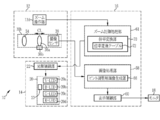
図6に示すように、ズーム制御処理部61は、ズーム操作部13dの操作がおこなわれた場合において、内視鏡12、光源装置14、プロセッサ装置16の全体を制御する。ズーム制御処理部61は、ズーム操作部13dが操作されると、光源制御部22に対して、紫色光V(本発明の「短波光」に対応する)のみを発光するように指示する。これにより、観察対象には、紫色光Vが照明される。撮像センサ38は、紫色光Vにより照明された観察対象を撮像することにより、Bp画像信号、Gp画像信号、及びRp画像信号を出力する。
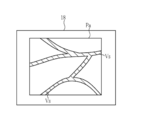
ピント調整用画像生成部66は、撮像センサ38から出力された画像信号のうちBp画像信号に基づいて、ピント調整用画像(本発明の「第1画像」に対応する)を生成する。生成されたピント調整用画像は、表示制御部60によって、モニタ18に表示される。ユーザーは、ピント調整用画像を観察しながら、観察対象を目標の大きさになるように、ズーム操作部13dを操作する。ここで、図7に示すように、ピント調整用画像Paは、血管のヘモグロビンの吸光係数が高い波長域の紫色光Vにより得られるBp画像信号から生成されているため、血管構造Vsなどのエッジ構造が高解像度で表示されている。なお、ピント調整用画像はモノクロの画像であるため、このピント調整用画像を、ズーム操作部13dの操作前に取得した通常画像と並列表示して、ピント合わせを行い易いようにしてもよい。また、モノクロのピント調整用画像に対して、階調バランスを複数の段階、例えば3段階で変え、それぞれの段階の画像をRGBの各chに割り当てたカラーのピント調整用画像をモニタ18に表示するようにしてもよい。
ピント調整用画像上では、観察対象にピントが合っていない場合には、血管構造などのエッジがぼけて表示される一方、観察対象にピントが合っている場合には、エッジが明確に表示される。したがって、ユーザーは、観察対象を目標の大きさに拡大した後は、ピント調整用画像におけるエッジがくっきり明確に表示されるように、ズーム操作部13dを操作する。そして、エッジがくっきり明確に表示されて、ズームレンズ36aが第1のレンズ位置になったときに、ズーム操作部13dの操作を停止する。ズーム操作部13dに対して一定時間以上操作がされない場合には、観察対象にピントが合ったものとみなし、この時点でのズームレンズ36aの倍率が、第1倍率としてズーム制御処理部61に送信される。
ズーム制御処理部61は、紫色光Vで照明された観察対象にピントが合ったときのズームレンズ36aの第1倍率を、通常光又は特殊光で照明された観察対象にピント合わせするための第2倍率に変換する倍率変換部70を有している。倍率変換部70は、倍率変換テーブル72を用いて、第1倍率から第2倍率への変換を行う。倍率変換テーブル72は、図8に示すように、第1倍率と、この第1倍率と同じような大きさで観察対象を拡大しつつ、且つ通常光により照明された観察対象にピント合わせするための通常光用の第2倍率とを関連付けている。係るテーブルは図示しないハードディスクやSSD(Solid State Drive)といった記録媒体に保存されている。合わせて、倍率変換テーブル72は、第1倍率とこの第1倍率と同じような大きさで観察対象を拡大しつつ、且つ特殊光で照明された観察対象にピント合わせするための特殊光用の第2倍率とを関連付けて記憶している。
なお、通常光用の第2倍率と特殊光用の第2倍率とが異なっているのは、通常光と特殊光とでは、赤色光Rのような長波光を含む割合が違っており、この長波光の割合の違いにより、通常光で照明した場合の観察対象にピントが合う位置と、観察対象とではピントが合う位置が異なるためである。また、倍率変換テーブル72は、食道、胃、大腸など部位毎に設けてもよい。この場合には、観察する部位の種類を、コンソール等を用いて手動で設定する、又は、画像による自動判定で設定することが好ましい。
また、倍率変換テーブル72は、例えば、人間の組織内における光散乱係数を模擬したファントムを用いて作成される。ファントムを用いる場合のテーブル作成方法としては、まず、紫色光Vをファントムに照明し、ズームレンズ36aを動かして、観察対象にピント合わせを行う。観察対象にピントが合ったときの倍率を、第1倍率とする。次に、通常光をファントムに照明して観察対象のピント合わせを行う。その際、第1倍率の前後で、ズームレンズ36aを動かして、ピント合わせを行う。ピントが合った時の倍率を通常光用の第2倍率とする。
これら第1倍率と通常光用の第2倍率とを関連付けて、倍率変換テーブル72に記憶する。一連の方法を、ズームレンズ36aの倍率を変えて行う。また、通常光を照明する場合のテーブルを作成したら、特殊光についても同様の方法でテーブルを作成する。なお、ファントムを用いてテーブルを作成する他、人間の組織内における光散乱係数を表現したモデリングに基づくシミュレーション計算により、テーブルを作成してもよい。
倍率変換部70は、設定されている観察モード及び倍率変換テーブル72を参照して、ズームレンズ36aの第1倍率に対応する第2倍率を選択する。例えば、図8に示す倍率変換テーブル72を用いる場合において、観察モードが通常モードに設定されており、第1倍率が10倍である場合には、第2倍率は、第1倍率を1.1倍した11倍となる。また、観察モードが通常モードに設定されており、第1倍率が10倍である場合には、第2倍率は、第1倍率を1.2倍した12倍となる。
ズーム制御処理部61は、ズームレンズ36aの倍率が、倍率変換部70において選択された第2倍率となるように、レンズ駆動部36bに対して指示を行う。これにより、ズームレンズ36aの倍率が、第1倍率から第2倍率に変更される。レンズ駆動部36bは公知のモーターにより構成される。これにより、ズームレンズ36aの位置が、第1のレンズ位置から第2のレンズ位置に移動する。また、ズーム制御処理部61は、光源制御部22に対して、観察モードに対応した照明光を発光するように指示する。この指示に従って、光源装置14から、通常モードの場合には通常光が観察対象に照明され、特殊モードの場合には特殊光が観察対象に照明される。そして、撮像センサ38により観察対象の撮像が行われることによって、観察モードに対応した画像(本発明の「第2画像」に対応する)が得られる。得られた画像はモニタ18に表示される。モニタ18に表示される画像は、観察対象がほぼ目標の大きさに拡大されており、且つ観察対象にピントが合っている画像となっている。
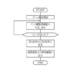
次に、ズームレンズを用いて、観察対象にピント合わせをする一連の流れについて、図9に示すフローチャートを用いて説明する。通常モード又は特殊モードに設定されている場合において、ズーム操作部13dが操作された場合には、光源制御部22は、V-LED20aを駆動して、紫色光Vを発光する。これにより、紫色光Vが観察対象に照明され、この紫色光Vにより照明された観察対象を撮像センサ38によって撮像して、Bp画像信号、Gp画像信号、Rp画像信号を得る。
ピント調整用画像生成部66は、Bp画像信号に基づいて、ピント調整用画像を生成する。ピント調整用画像はモニタ18に表示され、ユーザーはピント調整用画像を見て、観察対象にピントが合っているかどうかを確認する。その際、ユーザーは、観察対象にピントが合うように、ズーム操作部13dを操作してズームレンズ36aの位置を微調整する。そして、ユーザーが観察対象にピントが合ったと判断した場合には、ズーム操作部13dの操作を停止する。このときのズームレンズ36aの位置を第1のレンズ位置とする。このズーム操作部13dの操作を停止して一定時間経過した後、ズーム操作部13dの操作を停止した時のズームレンズ36aの第1倍率を、ズーム制御処理部61に送信する。
倍率変換部70は、ズームレンズ36aの第1倍率を、通常光又は特殊光により照明された観察対象にピント合わせするための第2倍率に変換する。ズーム制御処理部61は、ズームレンズ36aの倍率が、第1倍率から第2倍率に切り替えるように、レンズ駆動部36bに指示を行う。これにより、ズームレンズ36aの倍率が第2倍率に変更され、ズームレンズ36aの位置が第1のレンズ位置から第2のレンズ位置に移動する。また、ズーム制御処理部61は、V-LED20aの他、B-LED20b、G-LED20c、R-LED20dの全てを点灯して、通常光又は特殊光を発光するように、光源制御部22に対して指示を行う。これにより、観察対象には通常光又は特殊光が照明された、これら通常光又は特殊光で照明された観察対象を撮像することにより、通常画像又は特殊画像が得られる。通常画像又は特殊画像はモニタ18に表示される。
なお、上記実施形態では、ピント調整用画像を生成するために、紫色光Vにより観察対象を照明しているが、紫色光Vに代えて又は加えて、青色光Bxにより観察対象を照明するようにしてもよい。また、上記実施形態では、紫色光V、青色光Bx、緑色光G、赤色光Rの4色の光を全て照明し、光量比だけ異ならせた通常光又は特殊光を発光しているが、通常光又は特殊光に加えて、これら4色の光のうち、赤色光Rなどの長波光を少なくとも含む多色光を発光するようにしてもよい。この場合には、多色光により照明された観察対象にピントを合わせるために、倍率変換テーブル72に、第1倍率と、多色光用の第2倍率を関連付けて記憶しておく。
なお、上記実施形態では、ズームレンズ36aを第1のレンズ位置から第2のレンズ位置に切り替えた後に、観察対象に照明する光を、紫色光Vから通常光又は特殊光に切り替えるようにしているが、紫色光Vが照明された観察対象にピントが合った場合であれば、ズームレンズ36aを第1のレンズ位置から第2のレンズ位置に切り替える前に、観察対象に照明する光を、紫色光Vから通常光又は特殊光に切り替えるようにしてもよい。
[第2実施形態]
第2実施形態では、上記第1実施形態で示した4色のLED20a~20dの代わりに、レーザ光源と蛍光体を用いて観察対象の照明を行う。以下においては、第1実施形態と異なる部分のみ説明を行い、第1実施形態と略同様の部分については、説明を省略する。
第2実施形態では、上記第1実施形態で示した4色のLED20a~20dの代わりに、レーザ光源と蛍光体を用いて観察対象の照明を行う。以下においては、第1実施形態と異なる部分のみ説明を行い、第1実施形態と略同様の部分については、説明を省略する。
図10に示すように、第2実施形態の内視鏡システム100では、光源装置14の光源20において、4色のLED20a~20dの代わりに、中心波長445±10nmの青色レーザ光を発する青色レーザ光源(「445LD」と表記。LDは「Laser Diode」を表す)104と、中心波長405±10nmの青紫色レーザ光を発する青紫色レーザ光源(「405LD」と表記)106とが設けられている。これら各光源104、106の半導体発光素子からの発光は、光源制御部108により個別に制御されており、青色レーザ光源104の出射光と、青紫色レーザ光源106の出射光の光量比は変更自在になっている。
光源制御部108は、通常モードの場合には、青色レーザ光源104を点灯させる。これに対して、特殊モードの場合には、青色レーザ光源104と青紫色レーザ光源106の両方を点灯させるとともに、青色レーザ光の発光比率を青紫色レーザ光の発光比率よりも大きくなるように制御している。また、第2実施形態においては、通常モード又は特殊モードにおいて、ズーム操作部13dが操作された場合であっても、青色レーザ光源104及び青紫色レーザ光源106に対する光源制御は変更されない。
なお、青色レーザ光又は青紫色レーザ光の半値幅は±10nm程度にすることが好ましい。また、青色レーザ光源104及び青紫色レーザ光源106は、ブロードエリア型のInGaN系レーザダイオードが利用でき、また、InGaNAs系レーザダイオードやGaNAs系レーザダイオードを用いることもできる。また、上記光源として、発光ダイオードなどの発光体を用いた構成としてもよい。
照明光学系30aには、照明レンズ32の他に、ライトガイド24からの青色レーザ光又は青紫色レーザ光が入射する蛍光体110(波長変換部材)が設けられている。蛍光体110は、青色レーザ光によって励起され、蛍光を発する。また、青色レーザ光の一部は、蛍光体110を励起させることなく透過する。青紫色レーザ光は、蛍光体110を励起させることなく透過する。蛍光体110を出射した光は、照明レンズ32を介して、観察対象の体内を照明する。
ここで、通常モードにおいては、主として青色レーザ光が蛍光体110に入射するため、図11に示すような、青色レーザ光(本発明の「短波の狭帯域光」に対応する)、及び青色レーザ光により蛍光体110から励起発光する蛍光を合波した通常モード用の広帯域光が、通常光として、観察対象に照明される。この通常光で照明された観察対象を撮像センサ38により撮像することによって、Bc画像信号、Gc画像信号、Rc画像信号からなる通常画像が得られる。なお、第2実施形態では、本発明の「光源」は、青色レーザ光源104、青紫色レーザ光源106、及び蛍光体110を含む構成に対応する。
一方、特殊モードにおいては、青紫色レーザ光(本発明の「短波の狭帯域光」に対応する)と青色レーザ光の両方が蛍光体110に入射するため、図12に示すような、青紫色レーザ光、青色レーザ光、及び青色レーザ光により蛍光体110から励起発光する蛍光を合波した特殊モード用の広帯域光が、特殊光として、観察対象に照明される。この特殊光により照明された観察対象を撮像センサ38で撮像することによって、Bs画像信号、Gs画像信号、Rs画像信号からなる特殊画像が得られる。
なお、蛍光体110は、青色レーザ光の一部を吸収して、緑色~黄色に励起発光する複数種の蛍光体(例えばYAG系蛍光体、或いはBAM(BaMgAl10O17)などの蛍光体)を含んで構成されるものを使用することが好ましい。本構成例のように、半導体発光素子を蛍光体110の励起光源として用いれば、高い発光効率で高強度の白色光が得られ、白色光の強度を容易に調整できる上に、白色光の色温度、色度の変化を小さく抑えることができる。
なお、通常光と特殊光のスペクトルをそれぞれ比較すると、特殊光は、青色帯域などの短波帯域に、青紫色レーザ光のピークなどの光強度のピーク(本発明の「第1のピーク」に対応する)を持ち、且つ蛍光など短波帯域よりも長波長側に裾を持つスペクトルを有する光となっている。一方、通常光は、青色帯域など短波帯域に、青色レーザ光のピークなど光強度のピーク(本発明の「第2のピーク」に対応する)を有し、この通常光のピークは特殊光のピークよりも長波長側にあるスペクトルを有する光となっている。
第2実施形態では、ズーム操作部13dが操作された場合であっても光源制御の変更が無いことから、ズームレンズを用いて観察対象にピント合わせをする一連の流れが、第1実施形態と異なっている。この第2実施形態における一連の流れについて、図13に示すフローチャートを用いて説明する。通常モード又は特殊モードに設定されている場合において、ズーム操作部13dが操作された場合には、ピント調整用画像生成部66は、各モードで得られる画像信号のうち、短波光に対応する波長情報を有する画像信号に基づいて、ピント調整用画像を生成する。通常モードの場合であれば、Bc画像信号に基づいて、ピント調整用画像を生成し、特殊モードの場合であれば、Bs画像信号に基づいて、ピント調整用画像を生成する。
ピント調整用画像はモニタ18に表示され、ユーザーはピント調整用画像を見て、ズーム操作部13dの操作を行う。そして、ユーザーが観察対象にピントが合ったと判断した場合には、ズーム操作部13dの操作を停止する。このズーム操作部13dの操作を停止して一定時間経過した後、ズーム操作部13dの操作を停止した時のズームレンズ36aの第1倍率を、ズーム制御処理部61に送信する。
倍率変換部70は、ズームレンズ36aの第1倍率を、通常光又は特殊光により照明された観察対象にピント合わせするための第2倍率に変換する。レンズ駆動部36bは、ズームレンズ36aの倍率を、第1倍率から第2倍率に変更する。第2倍率への変更後に、通常光又は特殊光で観察対象を照明し、これら通常光又は特殊光により照明された観察対象を撮像する。これにより、観察対象にピントが合った通常画像又は特殊画像が得られる。通常画像又は特殊画像はモニタ18に表示される。
[第3実施形態]
第3実施形態では、4色のLED20a~20dの代わりに、キセノンランプ等の白色光源と回転フィルタを用いて観察対象の照明を行う。また、カラーの撮像センサ38に代えて、モノクロの撮像センサで観察対象の撮像を行っても良い。以下においては、第1実施形態と異なる部分のみ説明を行い、第1実施形態と略同様の部分については、説明を省略する。
第3実施形態では、4色のLED20a~20dの代わりに、キセノンランプ等の白色光源と回転フィルタを用いて観察対象の照明を行う。また、カラーの撮像センサ38に代えて、モノクロの撮像センサで観察対象の撮像を行っても良い。以下においては、第1実施形態と異なる部分のみ説明を行い、第1実施形態と略同様の部分については、説明を省略する。
図14に示す内視鏡システム200では、光源装置14において、内視鏡システム10の各LED20a~20dに代えて、白色光光源202と、回転フィルタ204と、フィルタ切替部206とが設けられている。また、撮像光学系30bには、カラーの撮像センサ38の代わりに、カラーフィルタが設けられていないモノクロの撮像センサ208が設けられている。なお、第3実施形態では、本発明の「光源」は、白色光光源202と回転フィルタ204とを含む構成に対応する。
白色光光源202はキセノンランプや白色LED等であり、波長域が青色から赤色に及ぶ白色光を発する。回転フィルタ204は、回転軸に近い一番近い内側に設けた通常モード用フィルタ210と、この通常モード用フィルタ210の外側に設けた特殊モード用フィルタ212とを備えている(図15参照)。
フィルタ切替部206は、回転フィルタ204を径方向に移動する。具体的には、フィルタ切替部206は、モード切替部13cにより通常モードにセットした場合に、通常モード用フィルタ210を白色光の光路に挿入する。フィルタ切替部206は、特殊モードにセットした場合に、特殊モード用フィルタ212を白色光の光路に挿入する。
図15に示すように、通常モード用フィルタ210には、周方向に沿って、Bbフィルタ210aと、Gフィルタ210bと、Rフィルタ210cとが設けられている。Bbフィルタ210aは、白色光のうち400~500nmの波長範囲を持つ広帯域の青色光Bbを透過する。Gフィルタ210bは、白色光のうち緑色光Gを透過する。Rフィルタ210cは、白色光のうち赤色光Rを透過する。したがって、通常モード時には、回転フィルタ204が回転することにより、通常光として、広帯域の青色光Bb(本発明の「短波光」に対応する)、緑色光G、赤色光R(本発明の「長波光」に対応する)が、観察対象に向けて、順次照射される。なお、第3実施形態では、通常モードにおいて、ズーム操作部13dが操作された場合であっても、回転フィルタ204は同様に駆動する。これは、特殊モードの場合も同様である。
特殊モード用フィルタ212には、周方向に沿って、Bnフィルタ212aと、Gnフィルタ212bとが設けられている。Bnフィルタ212aは、白色光のうち400~450nmの青色狭帯域光Bnを透過する。Gnフィルタ212bは、白色光のうち530~570nmの緑色狭帯域光Gnを透過する。したがって、特殊モード時には、回転フィルタ204が回転することにより、特殊光として、青色狭帯域光(本発明の「短波光」に対応する)、緑色狭帯域光(本発明の「長波光」に対応する)が、観察対象に向けて、順次照射される。
内視鏡システム200では、通常モード時には、広帯域の青色光Bb、緑色光G、赤色光Rで観察対象を照明する毎にモノクロの撮像センサ208で観察対象を撮像する。これにより、広帯域の青色光Bbの照明時にBc画像信号が得られ、緑色光Gの照明時にGc画像信号が得られ、赤色光Rの照明時にRc画像信号が得られる。これらBn画像信号、Gc画像信号とRc通常画像によって、通常画像が構成される。
特殊モード時には、青色狭帯域光Bn、緑色狭帯域光Gnで観察対象を照明する毎にモノクロの撮像センサ208で観察対象を撮像する。これにより、青色狭帯域光Bnの照明時にBn画像信号が得られ、緑色狭帯域光Gnの照射時にGn画像信号が得られる。これらBn画像信号とGn画像信号によって、特殊画像が構成される。
第3実施形態では、ズーム操作部13dが操作された場合であっても、観察対象に照明する光の切替は発生しないため、ズームレンズを用いて観察対象にピント合わせをする一連の流れが、第1実施形態と異なっている。この第3実施形態における一連の流れは、第2実施形態と同様であるため、説明を省略する(図13参照)。
なお、上記第1~第3実施形態では、観察対象を拡大するズームレンズを使用しているが、その他、光軸方向に移動する移動レンズであれば、本発明の実施は可能である。また、上記実施形態では、ズームレンズ36aの倍率を第1倍率から第2倍率に変えることによって、ズームレンズ36aの位置を、紫色光Vにより照明された観察対象にピントが合う第1のレンズ位置から、通常光又は特殊光で照明された観察対象にピントが合う第2のレンズ位置に移動させているが、その他の方法でズームレンズ36aの位置を変えてもよい。
例えば、図16に示すように、ズーム制御処理部61において、第1のレンズ位置と第2のレンズ位置の関係を予め記憶する位置変換テーブル80と、レンズ位置算出部82とを設けて、ズームレンズ36aの位置を変える方法を以下説明する。まず、上記実施形態と同様の方法で、紫色光Vにより照明された観察対象にピントを合わせて、このピントが合ったときのズームレンズ36aの第1のレンズ位置をレンズ位置算出部82に送信する。レンズ位置算出部82は、位置変換テーブル80を参照して、第1のレンズ位置から、通常光又は特殊光により照明された観察対象にピントが合う第2のレンズ位置を求める。第2のレンズ位置が求まると、レンズ駆動部36bは、ズームレンズ36aの位置を第1のレンズ位置から第2のレンズ位置に移動させる。
また、上記第1~第3実施形態において、通常モードにより通常画像をモニタ18に表示している場合においては、ズーム操作が行われたときに、一時的に、特殊モードに切り替えて、特殊画像をピント調整用画像としてモニタ18に表示するようにしてもよい。特殊画像は、血管構造などのエッジ構造が高解像度により表示される。したがって、特殊画像も、観察対象のピント合わせに適した画像となっている。なお、ピントが合ってズーム操作を停止した場合には、再び通常モードに切り替えて、通常画像をモニタ18に表示する。
10 内視鏡システム
12 内視鏡
12a 挿入部
12b 操作部
12c 湾曲部
12d 先端部
13a アングルノブ
13b 静止画像取得部
13c モード切替部
13d ズーム操作部
14 光源装置
16 プロセッサ装置
18 モニタ
19 コンソール
20 光源
20a V-LED
20b B-LED
20c G-LED
20d R-LED
22 光源制御部
23 波長カットフィルタ
24 ライトガイド
30a 照明光学系
30b 撮像光学系
32 照明レンズ
34 対物レンズ
36 拡大光学系
36a ズームレンズ
36b レンズ駆動部
38 撮像センサ
40 CDS/AGC回路
42 A/D変換回路
42 変換回路
50 画像信号取得部
52 DSP
54 ノイズ低減部
58 画像処理部
60 表示制御部
61 ズーム制御処理部
62 通常画像処理部
64 特殊画像処理部
66 ピント調整用画像生成部
70 倍率変換部
72 倍率変換テーブル
100 内視鏡システム
104 青色レーザ光源
106 青紫色レーザ光源
108 光源制御部
110 蛍光体
200 内視鏡システム
202 白色光光源
204 回転フィルタ
206 フィルタ切替部
208 撮像センサ
210 通常モード用フィルタ
210a Bbフィルタ
210b Gフィルタ
210c Rフィルタ
212 特殊モード用フィルタ
212a Bnフィルタ
212b Gnフィルタ
12 内視鏡
12a 挿入部
12b 操作部
12c 湾曲部
12d 先端部
13a アングルノブ
13b 静止画像取得部
13c モード切替部
13d ズーム操作部
14 光源装置
16 プロセッサ装置
18 モニタ
19 コンソール
20 光源
20a V-LED
20b B-LED
20c G-LED
20d R-LED
22 光源制御部
23 波長カットフィルタ
24 ライトガイド
30a 照明光学系
30b 撮像光学系
32 照明レンズ
34 対物レンズ
36 拡大光学系
36a ズームレンズ
36b レンズ駆動部
38 撮像センサ
40 CDS/AGC回路
42 A/D変換回路
42 変換回路
50 画像信号取得部
52 DSP
54 ノイズ低減部
58 画像処理部
60 表示制御部
61 ズーム制御処理部
62 通常画像処理部
64 特殊画像処理部
66 ピント調整用画像生成部
70 倍率変換部
72 倍率変換テーブル
100 内視鏡システム
104 青色レーザ光源
106 青紫色レーザ光源
108 光源制御部
110 蛍光体
200 内視鏡システム
202 白色光光源
204 回転フィルタ
206 フィルタ切替部
208 撮像センサ
210 通常モード用フィルタ
210a Bbフィルタ
210b Gフィルタ
210c Rフィルタ
212 特殊モード用フィルタ
212a Bnフィルタ
212b Gnフィルタ
Claims (14)
- 光軸方向に移動する移動レンズと、
短波光により照明された観察対象にピントが合っている場合における前記移動レンズの第1のレンズ位置から、前記短波光よりも長波長の長波光により照明された観察対象にピントが合う前記移動レンズの第2のレンズ位置に、前記移動レンズを移動させるレンズ駆動部とを備える内視鏡システム。 - 前記移動レンズが、観察対象を拡大するズームレンズである場合において、
前記ズームレンズが前記第1のレンズ位置のある場合の第1倍率と、前記ズームレンズが前記第2のレンズ位置にある場合の第2倍率とを関連付けて記憶する倍率変換テーブルと、
前記倍率変換テーブルを参照して、前記第1倍率から前記第2倍率に変換する倍率変換部とを有し、
前記レンズ駆動部は、前記ズームレンズを前記第2倍率にして、前記第2のレンズ位置に移動させる請求項1記載の内視鏡システム。 - 前記第1のレンズ位置と前記第2のレンズ位置との関係を記憶する位置変換テーブルと、
前記位置変換テーブルを参照して、前記第1のレンズ位置から前記第2のレンズ位置を求めるレンズ位置算出部とを有する請求項1記載の内視鏡システム。 - 紫色光、青色光、又は赤色光を含む複数色の光を独立して発光可能な光源を有し、
前記短波光は、前記紫色光又は前記青色光であり、
前記長波光は、前記複数色の光のうち前記赤色光を含む光であり、
前記紫色光又は前記青色光により照明された観察対象を撮像して得られる第1画像を表示部に表示する請求項1ないし3いずれか1項記載の内視鏡システム。 - 前記短波光を発光するための制御を、前記光源に対して行い、前記第1のレンズ位置から前記第2のレンズ位置に前記移動レンズを移動させた後に、前記短波光から前記長波光に切り替える制御を、前記光源に対して行う光源制御部を有する請求項4記載の内視鏡システム。
- 前記短波光を発光するための制御を、前記光源に対して行い、前記第1のレンズ位置から前記第2のレンズ位置に前記移動レンズを移動させる前に、前記短波光から前記長波光に切り替える制御を、前記光源に対して行う光源制御部を有する請求項4記載の内視鏡システム。
- 前記短波光は、短波帯域に第1のピークを持ち、且つ前記短波帯域よりも長波側に裾を持つスペクトルを有する光であり、
前記長波光は、前記第1のピークよりも長波長側に第2のピークを持つ光であり、
前記短波光により照明された観察対象を撮像して得られる第1画像を表示部に表示する請求項1ないし3いずれか1項記載の内視鏡システム。 - 複数色の光を独立して発光可能な光源を有し、
前記短波光又は前記長波光は、前記複数色の光を組み合わせて得られる多色光である請求項7記載の内視鏡システム。 - 前記短波光又は前記長波光は、1又は複数の短波の狭帯域光と、前記短波の狭帯域光を波長変換部材により波長変換して得られる蛍光とを含む広帯域光である請求項7記載の内視鏡システム。
- 前記短波光及び前記長波光を含む波長帯域を有する広帯域光を発光する光源と、
前記広帯域光により照明された観察対象の情報を有する複数帯域の画像のうち、前記短波光に対応する波長情報を有する第1画像を取得する画像取得部と、
前記第1画像を表示する表示部とを有する請求項1記載の内視鏡システム。 - 前記短波光と前記長波光とを順次発光する光源と、
前記短波光により照明された観察対象を撮像して得られる第1画像を取得する画像取得部と、
前記第1画像を表示する表示部とを有する請求項1記載の内視鏡システム。 - 前記長波光により照明された観察対象を撮像して得られる第2画像を取得する画像取得部と、
前記第2画像を表示する表示部を有する請求項1ないし11いずれか1項記載の内視鏡システム。 - 光軸方向に移動する移動レンズと、
短波光により照明された観察対象にピントが合っている場合における前記移動レンズの第1のレンズ位置から、前記短波光よりも長波長の長波光により照明された観察対象にピントが合う前記移動レンズの第2のレンズ位置に前記移動レンズを移動させるレンズ駆動部とを備え、
前記移動レンズが、観察対象を拡大するズームレンズである場合において、
前記ズームレンズが前記第1のレンズ位置のある場合の第1倍率と、前記ズームレンズが前記第2のレンズ位置にある場合の第2倍率とを関連付けて記憶する倍率変換テーブルと、
前記倍率変換テーブルを参照して、前記第1倍率から前記第2倍率に変換する倍率変換部とを有し、
前記レンズ駆動部は、前記ズームレンズを前記第2倍率にして、前記第2のレンズ位置に移動させる内視鏡システム。 - 光軸方向に移動する移動レンズを有する内視鏡システムの作動方法において、
レンズ駆動部が、短波光により照明された観察対象にピントが合っている場合における前記移動レンズの第1のレンズ位置から、前記短波光よりも長波長の長波光により照明された観察対象にピントが合う前記移動レンズの第2のレンズ位置に、前記移動レンズを移動させるステップとを有する内視鏡システムの作動方法。
Priority Applications (2)
| Application Number | Priority Date | Filing Date | Title |
|---|---|---|---|
| EP17855351.7A EP3520670B1 (en) | 2016-09-30 | 2017-07-07 | Endoscope system and method for operating same |
| US16/283,844 US11089949B2 (en) | 2016-09-30 | 2019-02-25 | Endoscope system and method of operating same |
Applications Claiming Priority (2)
| Application Number | Priority Date | Filing Date | Title |
|---|---|---|---|
| JP2016193133A JP6581952B2 (ja) | 2016-09-30 | 2016-09-30 | 内視鏡システム及びその作動方法 |
| JP2016-193133 | 2016-09-30 |
Related Child Applications (1)
| Application Number | Title | Priority Date | Filing Date |
|---|---|---|---|
| US16/283,844 Continuation US11089949B2 (en) | 2016-09-30 | 2019-02-25 | Endoscope system and method of operating same |
Publications (1)
| Publication Number | Publication Date |
|---|---|
| WO2018061392A1 true WO2018061392A1 (ja) | 2018-04-05 |
Family
ID=61763375
Family Applications (1)
| Application Number | Title | Priority Date | Filing Date |
|---|---|---|---|
| PCT/JP2017/024894 Ceased WO2018061392A1 (ja) | 2016-09-30 | 2017-07-07 | 内視鏡システム及びその作動方法 |
Country Status (4)
| Country | Link |
|---|---|
| US (1) | US11089949B2 (ja) |
| EP (1) | EP3520670B1 (ja) |
| JP (1) | JP6581952B2 (ja) |
| WO (1) | WO2018061392A1 (ja) |
Families Citing this family (9)
| Publication number | Priority date | Publication date | Assignee | Title |
|---|---|---|---|---|
| CN110325098A (zh) | 2016-11-28 | 2019-10-11 | 适内有限责任公司 | 具有可分离一次性轴的内窥镜 |
| WO2021009829A1 (ja) * | 2019-07-16 | 2021-01-21 | オリンパス株式会社 | 内視鏡用光源装置及び内視鏡装置 |
| USD1018844S1 (en) | 2020-01-09 | 2024-03-19 | Adaptivendo Llc | Endoscope handle |
| JP7452177B2 (ja) * | 2020-03-27 | 2024-03-19 | ソニーグループ株式会社 | 医療用観察システム、制御装置、制御方法、および撮像装置 |
| USD1051380S1 (en) | 2020-11-17 | 2024-11-12 | Adaptivendo Llc | Endoscope handle |
| USD1031035S1 (en) | 2021-04-29 | 2024-06-11 | Adaptivendo Llc | Endoscope handle |
| USD1070082S1 (en) | 2021-04-29 | 2025-04-08 | Adaptivendo Llc | Endoscope handle |
| USD1066659S1 (en) | 2021-09-24 | 2025-03-11 | Adaptivendo Llc | Endoscope handle |
| CN119632484A (zh) * | 2024-12-30 | 2025-03-18 | 深圳市星辰海医疗科技有限公司 | 一种内窥镜及其led照明装置 |
Citations (3)
| Publication number | Priority date | Publication date | Assignee | Title |
|---|---|---|---|---|
| JP2009022376A (ja) * | 2007-07-17 | 2009-02-05 | Hoya Corp | 電子内視鏡システム |
| JP2012110481A (ja) | 2010-11-24 | 2012-06-14 | Olympus Corp | 内視鏡装置、フォーカス制御方法及びプログラム |
| JP2014014716A (ja) * | 2013-10-17 | 2014-01-30 | Fujifilm Corp | 内視鏡装置 |
Family Cites Families (11)
| Publication number | Priority date | Publication date | Assignee | Title |
|---|---|---|---|---|
| JPS5846308A (ja) * | 1981-09-12 | 1983-03-17 | Fuji Photo Film Co Ltd | 固体撮像素子を移動する内視鏡用ズ−ムレンズ |
| US5662584A (en) * | 1994-10-07 | 1997-09-02 | Vista Medical Technologies, Inc. | Endoscope with position display for zoom lens unit and imaging device |
| EP1210907A1 (en) * | 2000-12-04 | 2002-06-05 | Fuji Photo Film Co., Ltd. | Fluorescent image obtaining apparatus |
| JP5606120B2 (ja) * | 2010-03-29 | 2014-10-15 | 富士フイルム株式会社 | 内視鏡装置 |
| JP5462084B2 (ja) * | 2010-06-21 | 2014-04-02 | オリンパス株式会社 | 画像処理装置及びプログラム |
| JP5603676B2 (ja) * | 2010-06-29 | 2014-10-08 | オリンパス株式会社 | 画像処理装置及びプログラム |
| JP5639522B2 (ja) * | 2011-03-31 | 2014-12-10 | 富士フイルム株式会社 | 電子内視鏡システム |
| JP5953187B2 (ja) * | 2011-10-11 | 2016-07-20 | オリンパス株式会社 | 合焦制御装置、内視鏡システム及び合焦制御方法 |
| JP6389140B2 (ja) * | 2015-04-03 | 2018-09-12 | 富士フイルム株式会社 | 内視鏡システム、プロセッサ装置、及び、内視鏡システムの作動方法 |
| CN107847107B (zh) * | 2015-07-15 | 2021-09-24 | 索尼公司 | 医疗用观察装置与医疗用观察方法 |
| JPWO2017221336A1 (ja) * | 2016-06-21 | 2019-04-11 | オリンパス株式会社 | 内視鏡システム、画像処理装置、画像処理方法およびプログラム |
-
2016
- 2016-09-30 JP JP2016193133A patent/JP6581952B2/ja active Active
-
2017
- 2017-07-07 EP EP17855351.7A patent/EP3520670B1/en active Active
- 2017-07-07 WO PCT/JP2017/024894 patent/WO2018061392A1/ja not_active Ceased
-
2019
- 2019-02-25 US US16/283,844 patent/US11089949B2/en active Active
Patent Citations (3)
| Publication number | Priority date | Publication date | Assignee | Title |
|---|---|---|---|---|
| JP2009022376A (ja) * | 2007-07-17 | 2009-02-05 | Hoya Corp | 電子内視鏡システム |
| JP2012110481A (ja) | 2010-11-24 | 2012-06-14 | Olympus Corp | 内視鏡装置、フォーカス制御方法及びプログラム |
| JP2014014716A (ja) * | 2013-10-17 | 2014-01-30 | Fujifilm Corp | 内視鏡装置 |
Non-Patent Citations (1)
| Title |
|---|
| See also references of EP3520670A4 |
Also Published As
| Publication number | Publication date |
|---|---|
| US20190183319A1 (en) | 2019-06-20 |
| EP3520670A4 (en) | 2019-09-11 |
| JP2018051143A (ja) | 2018-04-05 |
| JP6581952B2 (ja) | 2019-09-25 |
| EP3520670B1 (en) | 2021-06-23 |
| US11089949B2 (en) | 2021-08-17 |
| EP3520670A1 (en) | 2019-08-07 |
Similar Documents
| Publication | Publication Date | Title |
|---|---|---|
| JP6581952B2 (ja) | 内視鏡システム及びその作動方法 | |
| CN109068945B (zh) | 图像处理装置、图像处理装置的工作方法及记录介质 | |
| JP5460506B2 (ja) | 内視鏡装置の作動方法及び内視鏡装置 | |
| JP6243364B2 (ja) | 内視鏡用のプロセッサ装置、及び作動方法、並びに制御プログラム | |
| JP5460507B2 (ja) | 内視鏡装置の作動方法及び内視鏡装置 | |
| WO2018180631A1 (ja) | 医療用画像処理装置及び内視鏡システム並びに医療用画像処理装置の作動方法 | |
| JP7203477B2 (ja) | 内視鏡システム及びその作動方法 | |
| JP6690003B2 (ja) | 内視鏡システム及びその作動方法 | |
| US10003774B2 (en) | Image processing device and method for operating endoscope system | |
| WO2018061620A1 (ja) | プロセッサ装置及び内視鏡システム並びにプロセッサ装置の作動方法 | |
| JP6616071B2 (ja) | 内視鏡用のプロセッサ装置、内視鏡用のプロセッサ装置の作動方法、内視鏡用の制御プログラム | |
| JP5677555B2 (ja) | 内視鏡装置 | |
| JP6243311B2 (ja) | 内視鏡用のプロセッサ装置、内視鏡用のプロセッサ装置の作動方法、内視鏡用の制御プログラム | |
| JP2020192007A (ja) | 情報処理装置及びその作動方法並びに内視鏡システム及びその作動方法 | |
| WO2019163471A1 (ja) | 内視鏡システム | |
| JP7628871B2 (ja) | 医用画像処理装置及びその作動方法 | |
| JP2016067373A (ja) | 内視鏡用光源装置及び内視鏡システム | |
| JP2016144624A (ja) | 内視鏡光源装置、内視鏡システム、及び内視鏡光源装置の作動方法 | |
| WO2019159817A1 (ja) | 内視鏡システム及びその作動方法 | |
| JP6740481B2 (ja) | 光源装置、内視鏡システム、及び光源装置の作動方法 | |
| JP2016120026A (ja) | 内視鏡システム及びその作動方法 |
Legal Events
| Date | Code | Title | Description |
|---|---|---|---|
| 121 | Ep: the epo has been informed by wipo that ep was designated in this application |
Ref document number: 17855351 Country of ref document: EP Kind code of ref document: A1 |
|
| NENP | Non-entry into the national phase |
Ref country code: DE |
|
| ENP | Entry into the national phase |
Ref document number: 2017855351 Country of ref document: EP Effective date: 20190430 |