WO2018061902A1 - レンズ、レンズブランク及びアイウェア - Google Patents
レンズ、レンズブランク及びアイウェア Download PDFInfo
- Publication number
- WO2018061902A1 WO2018061902A1 PCT/JP2017/033821 JP2017033821W WO2018061902A1 WO 2018061902 A1 WO2018061902 A1 WO 2018061902A1 JP 2017033821 W JP2017033821 W JP 2017033821W WO 2018061902 A1 WO2018061902 A1 WO 2018061902A1
- Authority
- WO
- WIPO (PCT)
- Prior art keywords
- lens
- outer peripheral
- fresnel lens
- fresnel
- peripheral end
- Prior art date
- Legal status (The legal status is an assumption and is not a legal conclusion. Google has not performed a legal analysis and makes no representation as to the accuracy of the status listed.)
- Ceased
Links
Images


Classifications
-
- G—PHYSICS
- G02—OPTICS
- G02B—OPTICAL ELEMENTS, SYSTEMS OR APPARATUS
- G02B3/00—Simple or compound lenses
- G02B3/12—Fluid-filled or evacuated lenses
- G02B3/14—Fluid-filled or evacuated lenses of variable focal length
-
- G—PHYSICS
- G02—OPTICS
- G02C—SPECTACLES; SUNGLASSES OR GOGGLES INSOFAR AS THEY HAVE THE SAME FEATURES AS SPECTACLES; CONTACT LENSES
- G02C7/00—Optical parts
- G02C7/02—Lenses; Lens systems ; Methods of designing lenses
- G02C7/08—Auxiliary lenses; Arrangements for varying focal length
- G02C7/081—Ophthalmic lenses with variable focal length
- G02C7/083—Electrooptic lenses
-
- G—PHYSICS
- G02—OPTICS
- G02B—OPTICAL ELEMENTS, SYSTEMS OR APPARATUS
- G02B3/00—Simple or compound lenses
- G02B3/02—Simple or compound lenses with non-spherical faces
- G02B3/08—Simple or compound lenses with non-spherical faces with discontinuous faces, e.g. Fresnel lens
-
- G—PHYSICS
- G02—OPTICS
- G02C—SPECTACLES; SUNGLASSES OR GOGGLES INSOFAR AS THEY HAVE THE SAME FEATURES AS SPECTACLES; CONTACT LENSES
- G02C7/00—Optical parts
- G02C7/02—Lenses; Lens systems ; Methods of designing lenses
- G02C7/06—Lenses; Lens systems ; Methods of designing lenses bifocal; multifocal ; progressive
-
- G—PHYSICS
- G02—OPTICS
- G02C—SPECTACLES; SUNGLASSES OR GOGGLES INSOFAR AS THEY HAVE THE SAME FEATURES AS SPECTACLES; CONTACT LENSES
- G02C2202/00—Generic optical aspects applicable to one or more of the subgroups of G02C7/00
- G02C2202/20—Diffractive and Fresnel lenses or lens portions
-
- G—PHYSICS
- G02—OPTICS
- G02F—OPTICAL DEVICES OR ARRANGEMENTS FOR THE CONTROL OF LIGHT BY MODIFICATION OF THE OPTICAL PROPERTIES OF THE MEDIA OF THE ELEMENTS INVOLVED THEREIN; NON-LINEAR OPTICS; FREQUENCY-CHANGING OF LIGHT; OPTICAL LOGIC ELEMENTS; OPTICAL ANALOGUE/DIGITAL CONVERTERS
- G02F1/00—Devices or arrangements for the control of the intensity, colour, phase, polarisation or direction of light arriving from an independent light source, e.g. switching, gating or modulating; Non-linear optics
- G02F1/01—Devices or arrangements for the control of the intensity, colour, phase, polarisation or direction of light arriving from an independent light source, e.g. switching, gating or modulating; Non-linear optics for the control of the intensity, phase, polarisation or colour
- G02F1/13—Devices or arrangements for the control of the intensity, colour, phase, polarisation or direction of light arriving from an independent light source, e.g. switching, gating or modulating; Non-linear optics for the control of the intensity, phase, polarisation or colour based on liquid crystals, e.g. single liquid crystal display cells
- G02F1/133—Constructional arrangements; Operation of liquid crystal cells; Circuit arrangements
- G02F1/13306—Circuit arrangements or driving methods for the control of single liquid crystal cells
-
- G—PHYSICS
- G02—OPTICS
- G02F—OPTICAL DEVICES OR ARRANGEMENTS FOR THE CONTROL OF LIGHT BY MODIFICATION OF THE OPTICAL PROPERTIES OF THE MEDIA OF THE ELEMENTS INVOLVED THEREIN; NON-LINEAR OPTICS; FREQUENCY-CHANGING OF LIGHT; OPTICAL LOGIC ELEMENTS; OPTICAL ANALOGUE/DIGITAL CONVERTERS
- G02F1/00—Devices or arrangements for the control of the intensity, colour, phase, polarisation or direction of light arriving from an independent light source, e.g. switching, gating or modulating; Non-linear optics
- G02F1/29—Devices or arrangements for the control of the intensity, colour, phase, polarisation or direction of light arriving from an independent light source, e.g. switching, gating or modulating; Non-linear optics for the control of the position or the direction of light beams, i.e. deflection
- G02F1/294—Variable focal length devices
Definitions
- the present invention relates to a lens, a lens blank, and eyewear.
- Japanese Patent Application Laid-Open No. 2011-516927 and US Patent Application Publication No. 2013/0114128 disclose an eyewear lens and a lens blank forming the lens.
- the focal length of a part of the region can be changed.
- the focal length of the partial area is different from the focal distance of the other area.
- the lens described in Japanese Patent Application Laid-Open No. 2011-516927 and US Patent Application Publication No. 2013/0114128 has a narrow field of view when the user visually recognizes the object through a partial region of the lens. There is room for improvement in terms of suppressing this.
- the present invention is intended to obtain a lens, a lens blank, and eyewear that can suppress the narrowing of the field of view in consideration of the above facts.
- the lens includes a lens main body, a Fresnel lens portion provided on the lens main body, and formed with a plurality of convex portions and concave portions forming at least a part of a plurality of concentric circles.
- the outer shape of the Fresnel lens portion viewed from the light incident direction with respect to the lens body is a horizontally long shape, and at least a part of the first outer peripheral edge located at both ends in the longitudinal direction of the Fresnel lens portion is the A second outer peripheral end that forms an arc along a concentric circle and is located at both ends in the short direction of the Fresnel lens portion is inside the concentric circle that includes an arc formed by a part of the first outer peripheral end. And is connected to a part of the first outer peripheral end forming the circular arc via a bent portion.
- the Fresnel lens portion provided in the lens body has a plurality of convex portions and a plurality of concave portions, and the convex portions and the concave portions are at least a plurality of concentric circles. Part of it.
- the Fresnel lens portion is formed in a horizontally long shape. Thereby, it can suppress that the visual field to the longitudinal direction of a Fresnel lens part narrows.
- at least a part of the first outer peripheral edge located at both ends in the longitudinal direction of the Fresnel lens portion forms an arc along a concentric circle.
- the second outer peripheral edge located at both ends in the short direction of the Fresnel lens portion is located inside a concentric circle including an arc formed by a part of the first outer peripheral edge, and A part of the first outer peripheral end forming the arc is connected to the bent part.
- the part made into the circular arc which a part of 1st outer periphery end forms can be set optically continuously.
- the lens of the second embodiment is the lens of the first embodiment, and the second outer peripheral end has a shape along a straight line or a curve.
- the lens of the third embodiment is the lens of the second embodiment, wherein the second outer peripheral end is formed so as to intersect with the plurality of concentric circles to which an arc formed by the plurality of convex portions and concave portions belongs. Has been.
- the field of view in the short direction of the Fresnel lens portion is formed by forming the second outer peripheral ends, which are both ends in the short direction of the Fresnel lens portion, as described above. It is possible to obtain a desired visual field, and it is possible to suppress the narrowing of the visual field in the longitudinal direction of the Fresnel lens portion.
- the lens of the fourth embodiment is the lens of any one of the first to third embodiments, wherein the concentric circle including an arc formed by a part of the first outer peripheral end is included in the Fresnel lens portion. It is the largest circle among a plurality of concentric circles.
- a concentric circle including an arc formed by a part of the first outer peripheral end that is both ends in the longitudinal direction of the Fresnel lens portion is a plurality of concentric circles included in the Fresnel lens portion.
- the largest circle among them can further suppress the narrowing of the visual field in the longitudinal direction of the Fresnel lens portion.
- the lens of the fifth embodiment is the lens of any one of the first to fourth embodiments, and the Fresnel lens section includes a refractive index changing section that changes a refractive index when energized.
- the lens of the fifth embodiment when the refractive index changing portion provided in the Fresnel lens portion is energized, the refractive index of the refractive index changing portion changes. And in the lens of 5th Embodiment, it can suppress that an optical distortion arises in the outer periphery end of a Fresnel lens part, and it suppresses that the visual field through a Fresnel lens part and a refractive index change part narrows. be able to.
- the refractive index changing portion is a liquid crystal in the lens of the fifth embodiment.
- the lens of the sixth embodiment it is possible to suppress the narrowing of the field of view through the Fresnel lens portion and the liquid crystal.
- a plurality of portions that form arcs along the concentric circles are provided at the outer peripheral end of the Fresnel lens portion. ing.
- a plurality of portions that form arcs along a concentric circle are provided at the outer peripheral end of the Fresnel lens portion, thereby reducing the number of places where the field of view narrows at the outer peripheral end of the Fresnel lens portion. be able to.
- the lens of the eighth embodiment is the same as the lens of the seventh embodiment, but the portions forming the arcs along the plurality of concentric circles are located on the same circle.
- the center of the Fresnel lens portion (the center of the plurality of concentric circles). ) Can be prevented from being optically distorted at the same position, and the field of view of the Fresnel lens portion in the longitudinal direction can be prevented from narrowing.
- the lens of the ninth embodiment is the lens of the eighth embodiment, wherein the portions forming the arcs along the plurality of concentric circles are arranged to face each other with the centers of the plurality of concentric circles as a reference. ing.
- the centers of the plurality of concentric circles are used as a reference. It arrange
- the lens of the tenth embodiment is the lens of the first embodiment, and the outer shape of the Fresnel lens portion is a substantially barrel shape.
- the outer shape of the Fresnel lens portion is formed in a substantially barrel shape, it is possible to suppress a short field of view in the Fresnel lens portion from being narrowed.
- the dimension in the short direction of the Fresnel lens portion is gradually increased toward the central portion in the longitudinal direction of the Fresnel lens portion.
- the short dimension of the Fresnel lens unit is set so that the dimension in the short direction of the Fresnel lens unit gradually increases toward the center in the longitudinal direction of the Fresnel lens unit. Narrowing of the hand field of view can be suppressed.
- the longitudinal direction is a horizontal direction when the lens is used, and the short side direction is a vertical direction when the lens is used.
- the field of view of the Fresnel lens section is narrowed by setting the longitudinal direction to the horizontal direction in the lens usage state and setting the short side direction to the vertical direction in the lens usage state. Can be suppressed.
- the lens blank of the present invention is a lens blank of the lens according to any one of the first to twelfth embodiments, and includes a blank main body and the Fresnel lens portion provided on the blank main body.
- the lens blank of the present invention it is possible to prevent the field of view of the Fresnel lens portion of the lens formed using the lens blank from being narrowed.
- the first embodiment of the eyewear of the present invention includes a frame worn by a user and the lens of any one of the first to twelfth embodiments supported by the frame.
- the eyewear of the first embodiment it is possible to suppress the narrowing of the visual field when the user who uses the eyewear visually recognizes the object through the Fresnel lens portion of the lens supported by the frame.
- the Fresnel lens portion of the lens includes a refractive index changing portion that changes a refractive index when energized, and is attached to the frame. And a control unit that controls the refractive index changing unit, and has a function of changing the focal length of the lens.
- the refractive index of the refractive index changing unit can be changed by the control of the control unit.
- the frequency of the Fresnel lens part in the lens can be changed.
- the lens, the lens blank, and the eyewear according to the present invention have an excellent effect that the field of view can be suppressed from being narrowed.
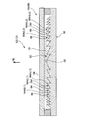
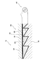
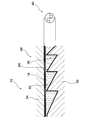
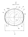
- FIG. 4 is an enlarged cross-sectional view showing an enlarged cross section of the lens cut along line 4-4 shown in FIG. 3; It is a front view which shows typically the Fresnel lens part of the lens shown by FIG. It is sectional drawing which shows the liquid crystal etc. of a to-be-energized state. It is sectional drawing corresponding to FIG. 5 which shows the liquid crystal etc. of an electricity supply state.
- FIG. 7 shows typically the Fresnel lens part concerning the 1st modification.
- arrow FR shown suitably in each figure has shown the front side seen from the user wearing electronic glasses
- arrow UP has shown the upper side
- arrows RH and LH have shown the right side and the left side.
- the vertical direction of the lens is a vertical direction or a vertical direction in use
- the left-right direction can also be referred to as a horizontal direction.
- the electronic glasses 10 of the present embodiment can change the focal length (frequency) of a part of the left and right lenses 12 and 14 by a user's switch operation.
- the electronic glasses 10 include a frame 16 worn by the user, a pair of left and right lenses 12 and 14 supported by the frame 16, and a liquid crystal 18 provided on the lenses 12 and 14 (see FIG. 4).
- a liquid crystal driving unit 20 as a control unit for driving the.
- the frame 16 has a right rim 22 and a left rim 24 formed in an annular shape (as viewed from the front side of the user of the electronic glasses 10) while the right lens 14 and the left lens 12 are supported respectively. And a bridge 26 that connects the right rim 22 and the left rim 24 in the left-right direction. A pad portion 28 that is locked to the user's nose is formed in a portion adjacent to the bridge 26 in the right rim 22 and the left rim 24.
- the frame 16 includes a right temple 30 attached to the right end of the right rim 22 so as to be tiltable, and a left temple 32 attached to the left end of the left rim 24 so as to be tiltable. .
- the right temple 30 includes a right temple body 34 having a groove portion 36 opened on the user side, and a groove portion 36 formed in the right temple body 34 by being attached to the right temple body 34. And a lid portion 38 to be closed.
- the liquid crystal driving unit 20 is for changing the arrangement of the liquid crystal 18 provided on the lens 12 described later.
- the liquid crystal driving unit 20 includes a control module 40 and a flexible cable connected to the control module 40. 42, a battery 44 and a switch 46.
- the control module 40 is disposed in the groove portion 36 of the right temple body 34, and the control module 40 is not exposed to the user side by attaching a lid portion 38 to the right temple body 34.
- the switch 46 is fixed to the opposite side of the right temple body 34 to the user (the side opposite to the side where the groove 36 is formed). Note that the switch 46 of the present embodiment is a capacitive touch switch that can be operated by touching the user.
- the battery 44 is detachably attached to the rear end portion of the right temple 30.
- the flexible cable 42 is routed from the control module 40 disposed in the right temple 30 to the upper portion of the right rim 22, the upper portion of the bridge 26 and the left rim 24.
- the left and right lenses 12 and 14 are fixed (fitted) to the right rim 22 and the left rim 24, respectively, so that the liquid crystal 18 provided on the lens 12 and the flexible cable 42 are connected to the electrodes 48 and 50 (FIG. 3). Connected).
- the lenses 12 and 14 which are the main parts of this embodiment will be described. Since the right lens 14 and the left lens 12 are formed symmetrically, the left lens 12 will be described in the following description, and the right lens 14 is the same as each part of the left lens 12. Reference numerals are assigned and explanations thereof are omitted.
- the lens 12 is formed by processing a lens blank 52 having a circular outer edge in a front view into a predetermined shape.
- the lens blank 52 includes a blank body 58 having a front lens 54 and a lens 56 with a diffractive portion which are overlapped and joined in the thickness direction.
- the front lens 54 and the diffraction part-equipped lens 56 constituting a part of the blank body 58 are gently curved so as to be convex forward.
- the front lens 54 and the lens 56 with a diffractive part are joined to a part excluding a part provided with a diffractive part 60 described later via an adhesive layer (not shown). Note that the electrodes 48 and 50 are disposed in the adhesive layer.
- a diffractive part 60 as a Fresnel lens part is provided in a part of the lens 56 with a diffractive part, and the diffractive part 60 has a so-called Fresnel cross-section on the front lens 54 side (front side).
- the lens configuration More specifically, on the front surface of the diffractive part 60, a hemispherical central spherical part 62 disposed at the central part of the diffractive part 60, a plurality of convex parts 64 and a plurality of convex parts 64 formed around the central spherical part 62.
- the recess 66 is formed.
- a line L1 connecting the leading ends 64A of the plurality of convex portions 64 in the protruding direction is a circle centered on the central spherical portion 62 when viewed from the front (viewed from the thickness direction of the lens blank 52 and the light incident direction with respect to the lens 12).
- the line L ⁇ b> 2 that is formed in an arc shape and connects the bottoms 66 ⁇ / b> A in the depression direction of the plurality of recesses 66 is formed in an arc shape centered on the central spherical portion 62 in a front view.
- the radius of the line L1 connecting the tip 64A in the projecting direction of the convex part 64 and the line L2 connecting the bottom 66A in the recess direction of the concave part 66 gradually increases as the distance from the central spherical part 62 increases.
- L1 and L2 form a part of a concentric circular arc centered on the central point of the central spherical portion 62.
- the recess 66 can also be referred to as a groove shape.
- “circle” means a perfect circle or a true circle.
- the “concentric circle” refers to at least one of two or more circles whose centers are at the same position.
- the liquid crystal 18 as a refractive index changing part that changes its refractive index when energized is interposed between the diffractive part 60 and the front lens 54 of the lens 56 with a diffractive part described above. It is disguised.
- the lens 12 is formed by processing a lens blank 52 into a shape corresponding to the left rim 24 (see FIG. 1).
- the lens body 68 of the lens 12 corresponds to the blank body 58 of the lens blank 52.
- FIG. 5 shows a front view schematically showing the diffractive portion 60 provided in the lens 12.
- the outer peripheral end 70 of the diffraction part 60 is drawn with the black thick line
- tip 64A of the protrusion direction of the convex part 64 is shown with the dashed-two dotted line.
- the dimension W1 in the left-right direction of the diffractive portion 60 is formed in a rectangular shape that is a horizontally long shape set to a dimension longer than the dimension W2 in the up-down direction.
- the upper end 70A and the lower end 70B as the second outer peripheral end of the outer peripheral end 70 of the diffractive portion 60 extend in parallel with each other in the left-right direction, and the upper end 70A and The lower end 70B intersects a line L1 connecting the tips 64A in the protruding direction of the plurality of convex portions 64 and a line L2 (see FIG. 4) connecting the bottom 66A in the depression direction of the plurality of concave portions 66.
- the right end 70 ⁇ / b> C and the left end 70 ⁇ / b> D as the first outer peripheral end of the outer peripheral end 70 of the diffractive portion 60 are formed along the convex portion 64 farthest from the central spherical portion 62.
- the upper end 70A and the lower end 70B of the outer peripheral end 70 are located inside a virtual concentric circle including an arc formed by the right end 70C and the left end 70D.
- the right end 70 ⁇ / b> C and the left end 70 ⁇ / b> D of the outer peripheral end 70 of the diffractive portion 60 may be formed along the recess 66 farthest from the central spherical portion 62.
- each outer peripheral end 70 is formed by a surface, and the surfaces of the outer peripheral end 70 are connected to each other at the bent portion 80.
- the switch 46 In the state where the switch 46 is not operated in the state in which the electronic glasses 10 shown in FIGS. 1 and 2 are worn, no voltage is applied to the liquid crystal 18 as shown in FIG.
- the refractive index of the liquid crystal 18 in a state where no voltage is applied is substantially the same as that of the front lens 54 and the lens 56 with a diffraction part. Therefore, the power of the portion where the diffractive portion 60 is provided in the left and right lenses 12 and 14 is substantially the same as the power of the portion around the diffractive portion 60.
- the arrangement of the liquid crystal 18 is changed and changed as shown in FIG.
- the refractive index of 18 changes.
- the power of the portion where the diffractive portion 60 is provided in the left and right lenses 12 and 14 is higher than the power of the portion around the diffractive portion 60 (the focal length of the portion where the diffractive portion 60 is provided is increased).
- the dimension W1 in the left-right direction of the diffractive portion 60 is set to be longer than the dimension W2 in the up-down direction. Thereby, it can suppress that the visual field to the left-right direction of the diffraction part 60 in the lenses 12 and 14 is narrowed.
- the right end 70 ⁇ / b> C and the left end 70 ⁇ / b> D of the outer peripheral end 70 of the diffractive portion 60 are formed along the convex portion 64 farthest from the center of the central spherical portion 62.
- the right end 70 ⁇ / b> C and the left end 70 ⁇ / b> D are concentric arcs formed by the convex portions 64 included in the diffractive portion 60 (the arc here is not only the arc of the entire circle but also a part of the circle).
- the arc of the largest circle is formed.
- the right end 70 ⁇ / b> C and the left end 70 ⁇ / b> D form part of an arc of the same circle among the circles centered on the center of the central spherical portion 62.
- the right end 70C and the left end 70D of the outer peripheral end 70 of the diffraction part can be set optically continuously along the vertical direction. As a result, it is possible to further suppress the narrowing of the visual field in the left-right direction of the diffraction unit 60.
- the upper end 70A and the lower end 70B of the outer peripheral end 70 of the diffraction section 60 are formed by straight lines extending in parallel with each other in the left-right direction. It is not limited to.
- the upper end 70A and the lower end 70B formed by straight lines in FIG. 5 may be formed by curves, respectively.
- FIG. 8 shows an example of this.
- the upper end 70 ⁇ / b> A at the outer peripheral end 70 of the diffractive portion 60 is formed by a curved curve that protrudes upward
- the lower end 70 ⁇ / b> B at the outer peripheral end 70 of the diffractive portion 60 is It is formed with a curved curve that is convex toward the lower side.
- the end 70A and the end 70B which are curved curved in a convex shape, are formed so as to be located inside a virtual concentric circle including an arc formed by the right end 70C and the left end 70D.
- the dimension W2 in the vertical direction of the diffractive portion 60 may be increased as it goes toward the center in the left-right direction. According to the said structure, it can suppress that the visual field to the up-down direction of the diffraction part 60 narrows compared with the diffraction part 60 described in FIG.
- the upper and lower side portions 70C1 of the right end 70C and the left and right end portions 70D1 of the outer peripheral end 70 of the diffractive portion 60 are center spherical portions. You may form in circular arc shape along the convex part 64 furthest away from the center of 62.
- FIG. At this time, 70C1 which is a part of the right end and 70D1 which is a part of the left end are concentric circular arcs formed by the convex portions 64 included in the diffractive portion 60 (the arc here is the whole circle)
- the arc of the largest circle is formed (including the arc that forms part of the circle).
- only the portion where it is desired to suppress the narrowing of the field of view of the diffractive portion 60 may be formed in an arc shape as described above.
- the end 70A, the end 70B, the end 70C, and the end 70D are formed by straight lines, but they may be formed by curves curved outward or inward.
- 70 ⁇ / b> C ⁇ b> 1 that is a part of the right end and 70 ⁇ / b> D ⁇ b> 1 that is a part of the left end are formed in an arc shape along the convex part 64 that is farthest from the center of the central spherical part 62.
- the end 70C and the end 70D are formed with straight lines.
- the end 70A and the end 70B are formed by curves curved outward.
- the end 70A, the end 70B, the end 70C, and the end 70D are formed so as to be located inside a virtual concentric circle including an arc formed by 70C1 and 70D1. Further, as shown in FIG. 10, by combining the diffractive part 60 shown in FIG. 8 and the diffractive part 60 shown in FIG. 9, the field of the diffractive part 60 becomes a desired field of view. Also good.
- the diffractive portion 60 at least all of the right end and the left end in the horizontal direction (left-right direction) of the outer peripheral end 70 of the diffractive portion 60.
- a part of the plurality of concentric circular arcs included in the diffractive portion 60 forms a part of the largest concentric circular arc, and an upper end 70A and a lower portion of the outer peripheral end 70 in the vertical direction of the diffractive portion 60
- the end 70B on the side is formed in a linear shape or a curved shape inside the arc of the maximum concentric circle.
- the shape of the diffractive portion 60 is a horizontally long shape as shown in FIGS. 5 and 8 to 10.
- FIGS. 8 and 10 have a barrel shape.
- the horizontally long shape is a shape including at least a substantially rectangular shape and a barrel shape. Thereby, the field of view in the horizontal direction (left-right direction) can be ensured in the diffraction unit 60. Further, all or part of the right end 70 ⁇ / b> C and the left end 70 ⁇ / b> D in the horizontal direction (left-right direction) is formed by a part of a concentric circular arc included in the diffractive portion 60, whereby the liquid crystal 18 in the diffractive portion 60. Is easy to fill.
- the upper and lower outer peripheries in the vertical direction are linearly or curvedly formed inside the concentric circular arc formed by all or part of the outer perimeter in the horizontal direction.
- the convex portion 64 forms part of the maximum concentric circular arc on the outer peripheral end forming a part of the maximum concentric circular arc among the right end 70C and the left end 70D in the horizontal direction (left-right direction).
- a part of the arc of the maximum concentric circle may be a part of the arc of the concentric circle formed by the concave part 66, or the convex part 64 and the concave part 66 adjacent thereto. It may be a part of a concentric arc located between the two.
- the present invention is not limited to this.
- the present invention can be applied to glasses as eyewear not provided with the liquid crystal 18 and lenses and lens blanks of the glasses.
- Lens body 10 Electronic glasses (eyewear) 12 lens 14 lens 16 frame 18 liquid crystal (refractive index changing portion) 20 Liquid crystal drive part 52 Lens blank 58 Blank body 60 Diffraction part (Fresnel lens part) 64 Projection 64A Projection protrusion tip L1 Line connecting projection projection tip 66 Recess 66A Bottom recess recess L2 Line connection recess bottom 68 Lens body 70A Upper end of outer edge End (second outer peripheral end) 70B Lower end of outer peripheral end (second outer peripheral end) 70C Right end of the outer peripheral end (first outer peripheral end) 70D Left edge of the outer edge (first outer edge) 80 bent part
Landscapes
- Physics & Mathematics (AREA)
- Health & Medical Sciences (AREA)
- Ophthalmology & Optometry (AREA)
- General Physics & Mathematics (AREA)
- Optics & Photonics (AREA)
- General Health & Medical Sciences (AREA)
- Liquid Crystal (AREA)
- Nonlinear Science (AREA)
- Eyeglasses (AREA)
Abstract
本発明は、視野が狭まることを抑制したレンズを提供する。レンズ12は、レンズ本体を備えている。レンズ本体には、少なくとも複数の同心円の一部を構成する複数の凸部64及び凹部66が形成されたフレネルレンズ部とが設けられている。また、レンズ本体に対する光の入射方向から見た回折部60の外形は横長形状であり、当該回折部60の長手方向の両端に位置する第1の外周端(外周端70における右側の端70C及び左側の端70D)の少なくとも一部が同心円に沿った円弧を形成している。さらに、当該回折部60の短手方向の両端に位置する第2の外周端(外周端70における上方側の端70A及び下方側の端70B)は、第1の外周端の一部が形成する円弧が含まれる同心円よりも内側に位置し、円弧を形成する第1の外周端の一部と屈曲部80を介して接続されている。
Description
本発明は、レンズ、レンズブランク及びアイウェアに関する。
特開2011-516927号公報及び米国特許出願公開第2013/0114128号明細書には、アイウェアのレンズ及び当該レンズを形成するレンズブランクが開示されている。特開2011-516927号公報に記載されたレンズでは、その一部の領域の焦点距離を変更することが可能となっており、米国特許出願公開第2013/0114128号明細書に記載されたレンズでは、その一部の領域の焦点距離が他の領域の焦点距離に対して異なっている。これにより、これらの文献に記載されたレンズを備えたアイウェアの使用者が、当該レンズの一部の領域を通じて当該使用者からの距離が近い物を視認する際の視認性を良好にする(拡大する)ことが可能となっている。
ところで、特開2011-516927号公報及び米国特許出願公開第2013/0114128号明細書に記載されたレンズには、使用者がレンズの一部の領域を通じて被対象物を視認する際の視野が狭まることを抑制するという点で改善の余地がある。
本発明は上記事実を考慮し、視野が狭まることを抑制することができるレンズ、レンズブランク及びアイウェアを得ることが目的である。
本発明のレンズの第1の実施形態において、レンズは、レンズ本体と、前記レンズ本体に設けられ、少なくとも複数の同心円の一部を構成する複数の凸部及び凹部が形成されたフレネルレンズ部と、を備え、前記レンズ本体に対する光の入射方向から見た前記フレネルレンズ部の外形は横長形状であり、該フレネルレンズ部の長手方向の両端に位置する第1の外周端の少なくとも一部が前記同心円に沿った円弧を形成し、該フレネルレンズ部の短手方向の両端に位置する第2の外周端は、前記第1の外周端の一部が形成する円弧が含まれる前記同心円よりも内側に位置し、前記円弧を形成する前記第1の外周端の一部と屈曲部を介して接続されている。
さらに第1の実施形態のレンズによれば、レンズ本体に設けられたフレネルレンズ部には、複数の凸部及び複数の凹部が形成されており、この凸部及び凹部は、少なくとも複数の同心円の一部を構成する。ここで、第1の実施形態のレンズでは、フレネルレンズ部が横長形状に形成されている。これにより、フレネルレンズ部の長手方向への視野が狭まることを抑制することができる。また、第1の実施形態のレンズでは、フレネルレンズ部の長手方向の両端に位置する第1の外周端の少なくとも一部が同心円に沿った円弧を形成している。これに加えて、フレネルレンズ部の短手方向の両端に位置する第2の外周端は、第1の外周端の一部が形成する円弧が含まれる同心円よりも内側に位置していると共に、この円弧を形成する第1の外周端の一部と屈曲部を介して接続されている。これにより、第1の外周端の一部が形成する円弧とされた部分を光学的に連続に設定することができる。その結果、フレネルレンズ部の外周端において光学的なひずみが生じることを抑制することができ、フレネルレンズ部の長手方向への視野が狭まることを抑制することができる。
第2の実施形態のレンズは、第1の実施形態のレンズにおいて、前記第2の外周端は、直線又は曲線に沿った形状である。
第3の実施形態のレンズは、第2の実施形態のレンズにおいて、前記第2の外周端は、前記複数の凸部及び凹部により形成される円弧が属する前記複数の同心円と交差するように形成されている。
第2及び第3の実施形態のレンズによれば、フレネルレンズ部の短手方向の両端である第2の外周端を上記のように形成することで、フレネルレンズ部の短手方向の視野を所望の視野にすることができると共に、フレネルレンズ部の長手方向への視野が狭まることを抑制することができる。
第4の実施形態のレンズは、第1~3ののいずれかの実施形態のレンズにおいて、前記第1の外周端の一部が形成する円弧が含まれる前記同心円は、前記フレネルレンズ部に含まれる複数の同心円のうち最大の円である。
第4の実施形態のレンズによれば、フレネルレンズ部の長手方向の両端である第1の外周端の一部が形成する円弧が含まれる同心円が、当該フレネルレンズ部に含まれる複数の同心円のうち最大の円であることにより、フレネルレンズ部の長手方向への視野が狭まることをより一層抑制することができる。
第5の実施形態のレンズは、第1~第4のいずれかの実施形態のレンズにおいて、前記フレネルレンズ部は、通電されることで屈折率が変化する屈折率変化部を備えている。
第5の実施形態のレンズによれば、フレネルレンズ部に設けられた屈折率変化部に通電がなされると、屈折率変化部の屈折率が変化する。そして、第5の実施形態のレンズでは、フレネルレンズ部の外周端において光学的なひずみが生じることを抑制することができることにより、フレネルレンズ部及び屈折率変化部を介する視野が狭まることを抑制することができる。
第6の実施形態のレンズは、第5の実施形態のレンズにおいて、前記屈折率変化部は液晶である。
第6の実施形態のレンズによれば、フレネルレンズ部及び液晶を介する視野が狭まることを抑制することができる。
第7の実施形態のレンズは、第1~第6のいずれかの実施形態のいずれかのレンズにおいて、前記フレネルレンズ部の外周端において、前記同心円に沿った円弧を形成する部分が複数設けられている。
第7の実施形態のレンズによれば、フレネルレンズ部の外周端において同心円に沿った円弧を形成する部分が複数設けられていることにより、フレネルレンズ部の外周端において視野が狭まる箇所を少なくすることができる。
第8の実施形態のレンズは、第7の実施形態のレンズにおいて、前記複数の前記同心円に沿った円弧を形成する部分は、同一の円上に位置する。
第8の実施形態のレンズによれば、フレネルレンズ部の外周端における円弧を形成する複数の部分が、同一の円上に位置していることにより、フレネルレンズ部の中心(複数の同心円の中心)からの距離が同じ位置において光学的なひずみが生じることを抑制することができ、フレネルレンズ部の長手方向への視野が狭まることを抑制することができる。
第9の実施形態のレンズは、第8の実施形態のレンズにおいて、前記複数の前記同心円に沿った円弧を形成する部分は、前記複数の同心円の中心を基準として、互いに対向するように配置されている。
第9の実施形態のレンズによれば、フレネルレンズ部の外周端における円弧を形成する複数の部分が、同一の円上に位置していることに加えて、複数の同心円の中心を基準として、互いに対向するように配置されている。これにより、フレネルレンズ部の中心からの距離が同じ位置で、かつ、フレネルレンズ部の中心を挟む対向位置において光学的なひずみが生じることを抑制することができる。
第10の実施形態のレンズは、第1の実施形態のレンズにおいて、前記フレネルレンズ部の外形は、略樽型の形状である。
第10の実施形態のレンズによれば、フレネルレンズ部の外形が略樽型の形状に形成されていることにより、フレネルレンズ部における短手の視野が狭まることを抑制することができる。
第11の実施形態のレンズは、第1の実施形態のレンズにおいて、前記フレネルレンズ部の短手方向の寸法が、該フレネルレンズ部の長手方向の中央部に向かうにつれて次第に大きくなっている。
第11の実施形態のレンズによれば、フレネルレンズ部の短手方向の寸法が、当該フレネルレンズ部の長手方向の中央部に向かうにつれて次第に大きくなるように設定することにより、フレネルレンズ部における短手の視野が狭まることを抑制することができる。
第12の実施形態のレンズは、第1の実施形態のレンズにおいて、前記長手方向が前記レンズの使用状態における水平方向であり、前記短手方向が前記レンズの使用状態における垂直方向である。
第12の実施形態のレンズによれば、長手方向をレンズの使用状態における水平方向に設定し、短手方向をレンズの使用状態における垂直方向に設定することにより、フレネルレンズ部の視野が狭まることを抑制することができる。
本発明のレンズブランクは、第1~第12のいずれかの実施形態のレンズのレンズブランクであり、ブランク本体と、前記ブランク本体に設けられた前記フレネルレンズ部と、を備えている。
本発明のレンズブランクによれば、当該レンズブランクを用いて形成されたレンズのフレネルレンズ部の視野が狭まることを抑制することができる。
本発明のアイウェアの第1の実施形態は、使用者に装着されるフレームと、前記フレームに支持された第1~第12のいずれかの実施形態のレンズと、を備えている。
第1の実施形態のアイウェアによれば、当該アイウェアを使用する使用者がフレームに支持されたレンズのフレネルレンズ部を通じて対象物を視認する際の視野が狭まることを抑制することができる。
アイウェアの第2の実施形態においては、第1の実施形態のアイウェアにおいて、前記レンズのフレネルレンズ部は、通電されることで屈折率が変化する屈折率変化部を含み、前記フレームに取り付けられ、前記屈折率変化部の制御を行う制御部を更に有し、レンズの焦点距離を変更する機能を備えている。
第2の実施形態のアイウェアによれば、制御部の制御により、屈折率変化部の屈折率を変化させることができる。これにより、レンズにおけるフレネルレンズ部の度数を変化させることができる。
本発明に係るレンズ、レンズブランク及びアイウェアは、視野が狭まることを抑制することができる、という優れた効果を有する。
図1~図5を用いて本発明の実施形態に係るアイウェアとしての電子メガネについて説明する。なお、各図において適宜示される矢印FRは電子メガネを装着した使用者から見た前側を示しており、矢印UPは上側を示しており、矢印RH及びLHは右側及び左側を示している。また、以下の説明で特記なく前後、上下、及び左右の方向を用いる場合は、電子メガネの使用者から見た前後、上下、及び左右を示すものとする。
また、レンズの上下方向とは使用状態における垂直方向または天地方向であり、左右方向とは水平方向と言い換えることもできる。
また、レンズの上下方向とは使用状態における垂直方向または天地方向であり、左右方向とは水平方向と言い換えることもできる。
図1及び図2に示されるように、本実施形態の電子メガネ10は、使用者のスイッチ操作により左右のレンズ12、14の一部の焦点距離(度数)を変更することが可能とされている。具体的には、電子メガネ10は、使用者に装着されるフレーム16と、フレーム16に支持された左右一対のレンズ12、14と、レンズ12、14に設けられた液晶18(図4参照)を駆動させる制御部としての液晶駆動部20と、を備えている。
フレーム16は、右側のレンズ14及び左側のレンズ12がそれぞれ支持されると共に正面視で(電子メガネ10の使用者の前方側から見て)環状に形成された右側リム22及び左側リム24と、右側リム22と左側リム24とを左右方向につなぐブリッジ26と、を備えている。また、右側リム22及び左側リム24においてブリッジ26と隣接する部分には、使用者の鼻に係止されるパッド部28が形成されている。また、フレーム16は、右側リム22の右側の端部に傾動可能に取付けられた右側テンプル30と、左側リム24の左側の端部に傾動可能に取付けられた左側テンプル32と、を備えている。図1に示されるように、右側テンプル30は、使用者側が開放された溝部36を有する右側テンプル本体34と、右側テンプル本体34に取付けられることで当該右側テンプル本体34に形成された溝部36を閉止する蓋部38と、を含んで構成されている。
液晶駆動部20は、後述するレンズ12に設けられた液晶18の配列を変更するためのものであり、この液晶駆動部20は、制御モジュール40と、当該制御モジュール40に接続された可撓ケーブル42、バッテリー44及びスイッチ46と、を備えている。制御モジュール40は、右側テンプル本体34の溝部36内に配置されており、また制御モジュール40は、右側テンプル本体34に蓋部38が取付けられることで、使用者側へ露出しないようになっている。また、スイッチ46は、右側テンプル本体34における使用者とは反対側(溝部36が形成された側とは反対側)に固定されている。なお、本実施形態のスイッチ46は、使用者が触れることでスイッチ操作することが可能とされた静電容量タッチスイッチである。また、バッテリー44は、右側テンプル30の後端部に着脱可能に取付けられるようになっている。可撓ケーブル42は、右側テンプル30内に配置された制御モジュール40から右側リム22の上方側の部位、ブリッジ26及び左側リム24の上方側の部位にかけて配索されている。そして、左右のレンズ12、14が右側リム22及び左側リム24にそれぞれ固定される(はめ込まれる)ことで、レンズ12に設けられた液晶18と可撓ケーブル42とが電極48、50(図3参照)を通じて接続されている。
次に、本実施形態の要部であるレンズ12、14について説明する。なお、右側のレンズ14と左側のレンズ12とは左右対称に形成されているため、以下の説明においては左側のレンズ12について説明し、右側のレンズ14については左側のレンズ12の各部と同一の符号を付してその説明を省略する。
図3に示されるように、レンズ12は、正面視で外縁が円形状とされたレンズブランク52が所定の形状に加工されることにより形成されている。
図3及び図4に示されるように、レンズブランク52は、その厚み方向に重ね合わされて接合された前面レンズ54及び回折部付レンズ56を有するブランク本体58を備えている。このブランク本体58の一部を構成する前面レンズ54及び回折部付レンズ56は、前方側へ凸状となるように緩やかに湾曲されている。また、前面レンズ54と回折部付レンズ56において後述する回折部60が設けられた部分を除く部分とは、図示しない接着層を介して接合されている。なお、この接着層内には、前述の電極48、50が配置されている。
回折部付レンズ56の一部には、フレネルレンズ部としての回折部60が設けられており、この回折部60は、前面レンズ54側(前面側)が鋸刃状の断面とされた所謂フレネルレンズの構成とされている。詳述すると、回折部60の前面には、当該回折部60の中心部に配置された半球面状の中心球状部62と、中心球状部62の回りに形成された複数の凸部64及び複数の凹部66と、が形成されている。また、複数の凸部64と複数の凹部66とは、中心球状部62と離間する方向に沿って交互に配置されている。さらに、複数の凸部64の突出方向の先端64Aを結ぶ線L1は、正面視で(レンズブランク52の厚み方向及びレンズ12に対する光の入射方向から見て)中心球状部62を中心とする円弧状に形成されており、複数の凹部66の窪み方向の底66Aを結ぶ線L2は、正面視で中心球状部62を中心とする円弧状に形成されている。そして、凸部64の突出方向の先端64Aを結ぶ線L1及び凹部66の窪み方向の底66Aを結ぶ線L2の半径は、中心球状部62と離間するにつれて次第に大きくなっている。言い換えると、L1及びL2は、中心球状部62の中心点を中心とした同心円の円弧の一部を形成している。また凹部66は溝形状ということもできる。
なお、以下の記述においては、「円」とは正円または真円を指す。また、「同心円」とは、中心が同じ位置にある二つ以上の円の内の少なくとも1つの円を指す。
なお、以下の記述においては、「円」とは正円または真円を指す。また、「同心円」とは、中心が同じ位置にある二つ以上の円の内の少なくとも1つの円を指す。
図4に示されるように、以上説明した回折部付レンズ56の回折部60と前面レンズ54との間には、通電されることで屈折率が変化する屈折率変化部としての液晶18が介装されている。
図3に示されるように、レンズ12は、レンズブランク52が左側リム24(図1参照)と対応する形状に加工されることにより形成されている。なお、レンズ12のレンズ本体68は、レンズブランク52のブランク本体58と対応している。
ここで、図5には、レンズ12に設けられた回折部60が模式的に示された正面図が示されている。なお、回折部60の外周端70が黒の太線で描かれており、凸部64の突出方向の先端64Aを結ぶ線L1が二点鎖線で示されている。また、本実施形態では、回折部60の左右方向への寸法W1が、上下方向への寸法W2よりも長い寸法に設定された横長形状である長方形状に形成されている。また、回折部60の外周端70における第2の外周端としての上方側の端70A及び下方側の端70Bは、それぞれ左右方向に沿って互いに平行に伸びており、この上方側の端70A及び下方側の端70Bは、複数の凸部64の突出方向の先端64Aを結ぶ線L1及び複数の凹部66の窪み方向の底66Aを結ぶ線L2(図4参照)と交差している。また、回折部60の外周端70における第1の外周端としての右側の端70C及び左側の端70Dは、中心球状部62から最も離れた凸部64に沿って形成されている。また、外周端70の上方側の端70A及び下方側の端70Bは、右側の端70C及び左側の端70Dにより形成される円弧を含む仮想的な同心円よりも内側に位置している。なお、回折部60の外周端70における右側の端70C及び左側の端70Dを中心球状部62から最も離れた凹部66に沿って形成してもよい。
以上説明した回折部60では、当該回折部60の外周端70における水平方向(左右方向)の右側の端70C及び左側の端70Dと、垂直方向(上下方向)の上方側の端70A及び下方側の端70Bとが、屈曲部80を介して接続されている。ここで、外周端70はそれぞれ面により形成されており、屈曲部80においては外周端70の面同士が接続されている。
(本実施形態の作用並びに効果)
次に、本実施形態の作用並びに効果について説明する。
次に、本実施形態の作用並びに効果について説明する。
図1及び図2に示された電子メガネ10を装着した状態においてスイッチ46の操作がなされていない状態では、図6に示されるように、液晶18には、電圧は印加されていない。ここで、電圧が印加されていない状態の液晶18の屈折率は、前面レンズ54及び回折部付レンズ56と略同一である。従って、左右のレンズ12、14において回折部60が設けられた部分の度数は、当該回折部60の回りの部分の度数と略同一である。
また、電子メガネ10の使用者によってスイッチ46の操作がなされることにより、液晶18に電圧が印加されると、図7に示されるように、液晶18の配列が変更され変化して、当該液晶18の屈折率が変化する。これにより、左右のレンズ12、14において回折部60が設けられた部分の度数が、当該回折部60の回りの部分の度数に比べて高くなる(回折部60が設けられた部分の焦点距離が、当該回折部60の回りの部分の焦点距離に比べて短くなる)。
ここで、図5に示されるように、本実施形態では、回折部60の左右方向への寸法W1が、上下方向への寸法W2よりも長い寸法に設定されている。これにより、レンズ12、14における回折部60の左右方向への視野が狭まることを抑制することができる。これに加えて、本実施形態では、回折部60の外周端70における右側の端70C及び左側の端70Dが、中心球状部62の中心から最も離れた凸部64に沿って形成されている。つまり、右側の端70C及び左側の端70Dは、回折部60に含まれる、凸部64が形成する同心円の円弧(ここでいう円弧とは、円全体の円弧だけでなく、円の一部を構成する円弧を含む)のうち、最大の円の円弧を形成している。右側の端70C及び左側の端70Dは中心球状部62の中心を中心とした円のうち同一の円の円弧の一部をそれぞれ形成しているとも言い換えることもできる。これにより、回折部の外周端70における右側の端70C及び左側の端70Dをその上下方向に沿って光学的に連続に設定することができる。その結果、回折部60の左右方向への視野が狭まることをより一層抑制することができる。
なお、本実施形態では、回折部60の外周端70における上方側の端70A及び下方側の端70Bをそれぞれ左右方向に沿って互いに平行に伸ばした直線で形成しているが、本発明はこれに限定されない。例えば、図5にて直線で形成された上方側の端70A及び下方側の端70Bを、それぞれ曲線で形成するようにしてもよい。図8にこの例を示す。図8においては、回折部60の外周端70における上方側の端70Aは上方側へ向けて凸状に湾曲した曲線で形成されており、回折部60の外周端70における下方側の端70Bは下方側へ向けて凸状に湾曲した曲線で形成されている。このとき、凸状に湾曲した曲線である端70A及び端70Bは、右側の端70C及び左側の端70Dにより形成される円弧を含む仮想的な同心円よりも内側に位置するように形成される。なお、回折部60の上下方向への寸法W2が左右方向の中央部に向かうにつれて大きくなるようにしてもよい。当該構成によれば、図5に記載された回折部60に比べて、回折部60の上下方向への視野が狭まることを抑制することができる。
また、図9に示された回折部60のように、回折部60の外周端70における右側の端70Cの上下方向の両側部分70C1及び左側の端70Dの上下方向の両側部分70D1を中心球状部62の中心から最も離れた凸部64に沿って円弧状に形成してもよい。このとき、右側の端の一部である70C1及び左側の端の一部である70D1は、回折部60に含まれる、凸部64が形成する同心円の円弧(ここでいう円弧とは、円全体の円弧だけでなく、円の一部を構成する円弧を含む)うち、最大の円の円弧を形成している。このように、回折部60の視野が狭くなることを抑制したい部分のみを上記のように円弧状に形成してもよい。
なお、図9では、端70A、端70B、端70C及び端70Dを直線で形成しているが、これらを外側又は内側に向かって湾曲した曲線により形成してもよい。図10は、図9同様に、右側の端の一部である70C1及び左側の端の一部である70D1は、中心球状部62の中心から最も離れた凸部64に沿って円弧状に形成されており、端70C及び端70Dは直線で形成されている。一方で、端70A及び端70Bは、外側に湾曲した曲線により形成されている。このとき、端70A、端70B、端70C及び端70Dは、70C1及び70D1により形成される円弧を含む仮想的な同心円よりも内側に位置するように形成される。さらに、図10に示されるように、図8に示された回折部60と図9に示された回折部60の構成を組み合わせることにより、回折部60の視野が所望の視野となるようにしてもよい。
図5、図8~図10には、種々の形状の回折部60を示した通り、回折部60の外周端70のうち、少なくとも水平方向(左右方向)の右側の端及び左側の端の全部または一部が、回折部60に含まれる複数の同心円の円弧のうち、最大の同心円の円弧の一部を形成するとともに、回折部60の垂直方向の外周端70における上方側の端70A及び下方側の端70Bは、上記最大の同心円の円弧よりも内側において直線状または曲線状に形成されている。これにより、回折部60の形状は、図5、図8~図10に示す通り、横長の形状となっている。図5及び図9は長方形に近い略長方形の形状をしており、図8及び図10は樽型の形状をしている。横長の形状とは、少なくとも、これら略長方形及び樽型の形状を含む形状である。これにより、回折部60において水平方向(左右方向)の視界を確保することができる。また、水平方向(左右方向)の右側の端70C及び左側の端70Dの全部または一部が、回折部60に含まれる同心円の円弧の一部により形成されることで、回折部60における液晶18の充填が容易となる。更には、垂直方向の上方側及び下方側の外周が、水平方向の外周の全部または一部が形成する同心円の円弧よりも内側において直線状または曲線状に形成されていることにより、回折部の垂直方向の大きさを小さくすることで、横長のメガネフレームにおいても回折部以外のレンズの視野を確保することが可能となる。
なお、水平方向(左右方向)の右側の端70C及び左側の端70Dのうち最大の同心円の円弧の一部を形成する外周端について、最大の同心円の円弧の一部は凸部64が形成する同心円の一部である例を示したが、最大の同心円の円弧の一部は凹部66により形成される同心円の円弧の一部であってもよいし、凸部64及びこれと隣り合う凹部66の間に位置する同心円の円弧の一部であってもよい。
さらに、本実施形態では、電圧が印加される(通電される)ことで屈折率が変化する液晶18を設けた例について説明したが、本発明はこれに限定されない。例えば、液晶18が設けられていないアイウェアとしてのメガネ及び当該メガネのレンズ及びレンズブランクに本発明を適用することもできる。
以上、本発明の一実施形態について説明したが、本発明は、上記に限定されるものでなく、その主旨を逸脱しない範囲内において上記以外にも種々変形して実施することが可能であることは勿論である。
本出願は、2016年9月29日出願の特願2016-191870に基づく優先権を主張する。当該出願明細書に記載された内容は、全て本願明細書に援用される。
10 電子メガネ(アイウェア)
12 レンズ
14 レンズ
16 フレーム
18 液晶(屈折率変化部)
20 液晶駆動部
52 レンズブランク
58 ブランク本体
60 回折部(フレネルレンズ部)
64 凸部
64A 凸部の突出方向の先端
L1 凸部の突出方向の先端を結ぶ線
66 凹部
66A 凹部の窪み方向の底
L2 凹部の窪み方向の底を結ぶ線
68 レンズ本体
70A 外周端の上方側の端(第2の外周端)
70B 外周端の下方側の端(第2の外周端)
70C 外周端の右側の端(第1の外周端)
70D 外周端の左側の端(第1の外周端)
80 屈曲部
12 レンズ
14 レンズ
16 フレーム
18 液晶(屈折率変化部)
20 液晶駆動部
52 レンズブランク
58 ブランク本体
60 回折部(フレネルレンズ部)
64 凸部
64A 凸部の突出方向の先端
L1 凸部の突出方向の先端を結ぶ線
66 凹部
66A 凹部の窪み方向の底
L2 凹部の窪み方向の底を結ぶ線
68 レンズ本体
70A 外周端の上方側の端(第2の外周端)
70B 外周端の下方側の端(第2の外周端)
70C 外周端の右側の端(第1の外周端)
70D 外周端の左側の端(第1の外周端)
80 屈曲部
Claims (15)
- レンズ本体と、
前記レンズ本体に設けられ、少なくとも複数の同心円の一部を構成する複数の凸部及び凹部が形成されたフレネルレンズ部と、
を備え、
前記レンズ本体に対する光の入射方向から見た前記フレネルレンズ部の外形は横長形状であり、
該フレネルレンズ部の長手方向の両端に位置する第1の外周端の少なくとも一部が前記同心円に沿った円弧を形成し、
該フレネルレンズ部の短手方向の両端に位置する第2の外周端は、前記第1の外周端の一部が形成する円弧が含まれる前記同心円よりも内側に位置し、前記円弧を形成する前記第1の外周端の一部と屈曲部を介して接続されているレンズ。 - 前記第2の外周端は、直線又は曲線に沿った形状である請求項1に記載のレンズ。
- 前記第2の外周端は、前記複数の凸部及び凹部により形成される円弧が属する前記複数の同心円と交差するように形成されている請求項2に記載のレンズ。
- 前記第1の外周端の一部が形成する円弧が含まれる前記同心円は、前記フレネルレンズ部に含まれる複数の同心円のうち最大の円である請求項1~請求項3のいずれか1項に記載のレンズ。
- 前記フレネルレンズ部は、通電されることで屈折率が変化する屈折率変化部を備えている請求項1~請求項4のいずれか1項に記載のレンズ。
- 前記屈折率変化部は液晶である請求項5に記載のレンズ。
- 前記フレネルレンズ部の外周端において、前記同心円に沿った円弧を形成する部分が複数設けられている請求項1~請求項6のいずれか1項に記載のレンズ。
- 前記複数の前記同心円に沿った円弧を形成する部分は、同一の円上に位置する請求項7に記載のレンズ。
- 前記複数の前記同心円に沿った円弧を形成する部分は、前記複数の同心円の中心を基準として、互いに対向するように配置されている請求項8に記載のレンズ。
- 前記フレネルレンズ部の外形は、略樽型の形状である請求項1に記載のレンズ。
- 前記フレネルレンズ部の短手方向の寸法が、該フレネルレンズ部の長手方向の中央部に向かうにつれて次第に大きくなっている請求項1に記載のレンズ。
- 前記長手方向は前記レンズの使用状態における水平方向であり、前記短手方向は前記レンズの使用状態における垂直方向である、請求項1に記載のレンズ。
- ブランク本体と、
前記ブランク本体に設けられた前記フレネルレンズ部と、
を備えた請求項1~請求項12のいずれか1項に記載のレンズのレンズブランク。 - 使用者に装着されるフレームと、
前記フレームに支持された請求項1~請求項12のいずれか1項に記載のレンズと、
を備えたアイウェア。 - 前記レンズのフレネルレンズ部は、通電されることで屈折率が変化する屈折率変化部を含み、
前記フレームに取り付けられ、前記屈折率変化部の制御を行う制御部を更に有し、レンズの焦点距離を変更する機能を備えた請求項14に記載のアイウェア。
Priority Applications (4)
| Application Number | Priority Date | Filing Date | Title |
|---|---|---|---|
| EP17855857.3A EP3521906A4 (en) | 2016-09-29 | 2017-09-20 | EYE GLASS, EYE GLASS BLANK AND EYEGLASSES |
| JP2018542442A JPWO2018061902A1 (ja) | 2016-09-29 | 2017-09-20 | レンズ、レンズブランク及びアイウェア |
| CN201780058656.0A CN109791309A (zh) | 2016-09-29 | 2017-09-20 | 镜片、透镜坯件以及眼睛佩戴物 |
| US16/338,032 US20200026098A1 (en) | 2016-09-29 | 2017-09-20 | Lens, lens blank, and eyewear |
Applications Claiming Priority (2)
| Application Number | Priority Date | Filing Date | Title |
|---|---|---|---|
| JP2016-191870 | 2016-09-29 | ||
| JP2016191870 | 2016-09-29 |
Publications (1)
| Publication Number | Publication Date |
|---|---|
| WO2018061902A1 true WO2018061902A1 (ja) | 2018-04-05 |
Family
ID=61759681
Family Applications (1)
| Application Number | Title | Priority Date | Filing Date |
|---|---|---|---|
| PCT/JP2017/033821 Ceased WO2018061902A1 (ja) | 2016-09-29 | 2017-09-20 | レンズ、レンズブランク及びアイウェア |
Country Status (5)
| Country | Link |
|---|---|
| US (1) | US20200026098A1 (ja) |
| EP (1) | EP3521906A4 (ja) |
| JP (2) | JPWO2018061902A1 (ja) |
| CN (1) | CN109791309A (ja) |
| WO (1) | WO2018061902A1 (ja) |
Cited By (3)
| Publication number | Priority date | Publication date | Assignee | Title |
|---|---|---|---|---|
| JPWO2018146858A1 (ja) * | 2017-02-07 | 2019-11-07 | 三井化学株式会社 | レンズ、レンズブランクおよびアイウェア |
| JP2020173469A (ja) * | 2016-09-29 | 2020-10-22 | 三井化学株式会社 | レンズ、レンズブランク及びアイウェア |
| JP2025035330A (ja) * | 2023-09-01 | 2025-03-13 | キヤノン株式会社 | 回折光学素子及び光学機器 |
Families Citing this family (1)
| Publication number | Priority date | Publication date | Assignee | Title |
|---|---|---|---|---|
| CN117572664A (zh) * | 2023-11-06 | 2024-02-20 | 阿尔玻科技有限公司 | 眼视光学镜片及眼镜 |
Citations (5)
| Publication number | Priority date | Publication date | Assignee | Title |
|---|---|---|---|---|
| US5731862A (en) * | 1994-07-08 | 1998-03-24 | Eschenbach Optik Gmbh + Co. | Hyperocular lens assembly attachable to an eyeglass lens |
| JP2010532496A (ja) * | 2007-07-03 | 2010-10-07 | ピクセルオプティクス, インコーポレイテッド | 回折光学パワー領域を備えた多焦点レンズ |
| JP2011053660A (ja) * | 2009-08-05 | 2011-03-17 | Hoya Corp | 偏光レンズ |
| JP2011516927A (ja) | 2008-04-11 | 2011-05-26 | ピクセルオプティクス, インコーポレイテッド | 電気活性回折レンズおよびそれを作るための方法 |
| JP2016191870A (ja) | 2015-03-31 | 2016-11-10 | 三菱電機株式会社 | 液晶表示装置 |
Family Cites Families (10)
| Publication number | Priority date | Publication date | Assignee | Title |
|---|---|---|---|---|
| JPS61156227A (ja) * | 1984-12-28 | 1986-07-15 | Olympus Optical Co Ltd | フレネル液晶眼鏡 |
| BRPI0713008A2 (pt) * | 2006-06-12 | 2012-10-09 | Pixeloptics Inc | região de superfìcie progressiva de estática em uma comunicação óptica com um ótico dinámico |
| WO2010102295A1 (en) * | 2009-03-06 | 2010-09-10 | The Curators Of The University Of Missouri | Adaptive lens for vision correction |
| WO2011132789A1 (ja) * | 2010-04-19 | 2011-10-27 | シチズンホールディングス株式会社 | エッジング前レンズ及びエッジングレンズの製造方法 |
| CN103298603B (zh) * | 2011-01-04 | 2017-01-18 | 埃西勒国际通用光学公司 | 制造具有结构化表面的眼科透镜的方法 |
| EP2793072B1 (en) * | 2011-12-16 | 2019-10-09 | Mitsui Chemicals, Inc. | Control device for variable focus lenses, control method for variable focus lenses, and electronic glasses |
| IN2014DN06813A (ja) * | 2012-02-27 | 2015-05-22 | E Vision Smart Optics Inc | |
| US9442305B2 (en) * | 2012-06-14 | 2016-09-13 | Mitsui Chemicals, Inc. | Electronic eyeglasses and methods of manufacturing |
| CN104090381A (zh) * | 2014-07-21 | 2014-10-08 | 段亚东 | 一种鼻侧颞侧区周边离焦框架眼镜片 |
| WO2018061902A1 (ja) * | 2016-09-29 | 2018-04-05 | 三井化学株式会社 | レンズ、レンズブランク及びアイウェア |
-
2017
- 2017-09-20 WO PCT/JP2017/033821 patent/WO2018061902A1/ja not_active Ceased
- 2017-09-20 US US16/338,032 patent/US20200026098A1/en not_active Abandoned
- 2017-09-20 CN CN201780058656.0A patent/CN109791309A/zh active Pending
- 2017-09-20 JP JP2018542442A patent/JPWO2018061902A1/ja active Pending
- 2017-09-20 EP EP17855857.3A patent/EP3521906A4/en not_active Withdrawn
-
2020
- 2020-06-30 JP JP2020113290A patent/JP2020173469A/ja active Pending
Patent Citations (6)
| Publication number | Priority date | Publication date | Assignee | Title |
|---|---|---|---|---|
| US5731862A (en) * | 1994-07-08 | 1998-03-24 | Eschenbach Optik Gmbh + Co. | Hyperocular lens assembly attachable to an eyeglass lens |
| JP2010532496A (ja) * | 2007-07-03 | 2010-10-07 | ピクセルオプティクス, インコーポレイテッド | 回折光学パワー領域を備えた多焦点レンズ |
| US20130114128A1 (en) | 2007-07-03 | 2013-05-09 | PixelOptics, Inc. (027497) | Multifocal lens with a diffractive optical power region |
| JP2011516927A (ja) | 2008-04-11 | 2011-05-26 | ピクセルオプティクス, インコーポレイテッド | 電気活性回折レンズおよびそれを作るための方法 |
| JP2011053660A (ja) * | 2009-08-05 | 2011-03-17 | Hoya Corp | 偏光レンズ |
| JP2016191870A (ja) | 2015-03-31 | 2016-11-10 | 三菱電機株式会社 | 液晶表示装置 |
Non-Patent Citations (1)
| Title |
|---|
| See also references of EP3521906A4 |
Cited By (4)
| Publication number | Priority date | Publication date | Assignee | Title |
|---|---|---|---|---|
| JP2020173469A (ja) * | 2016-09-29 | 2020-10-22 | 三井化学株式会社 | レンズ、レンズブランク及びアイウェア |
| JPWO2018146858A1 (ja) * | 2017-02-07 | 2019-11-07 | 三井化学株式会社 | レンズ、レンズブランクおよびアイウェア |
| JP2025035330A (ja) * | 2023-09-01 | 2025-03-13 | キヤノン株式会社 | 回折光学素子及び光学機器 |
| JP7739370B2 (ja) | 2023-09-01 | 2025-09-16 | キヤノン株式会社 | 回折光学素子及び光学機器 |
Also Published As
| Publication number | Publication date |
|---|---|
| CN109791309A (zh) | 2019-05-21 |
| JP2020173469A (ja) | 2020-10-22 |
| JPWO2018061902A1 (ja) | 2019-02-21 |
| US20200026098A1 (en) | 2020-01-23 |
| EP3521906A4 (en) | 2020-06-17 |
| EP3521906A1 (en) | 2019-08-07 |
Similar Documents
| Publication | Publication Date | Title |
|---|---|---|
| JP2020173469A (ja) | レンズ、レンズブランク及びアイウェア | |
| CN104678572B (zh) | 眼镜片 | |
| CN111630441B (zh) | 眼睛佩戴物 | |
| JP7073455B2 (ja) | レンズ、レンズブランクおよびアイウェア | |
| US11886048B2 (en) | Lens and eyewear | |
| JP2007530150A (ja) | ゴーグルレンズ | |
| EP3936093B1 (en) | Eye protection structure | |
| KR20180137551A (ko) | 확대 커버를 갖는 용접 보호기 | |
| JP2007089748A (ja) | ゴーグル | |
| JP3227701U (ja) | フェースシールド | |
| CN101896854A (zh) | 二重焦点透镜和远近两用眼镜 | |
| KR102507893B1 (ko) | 보안 구조체 | |
| JP2013073177A (ja) | ヘッドマウントディスプレイ | |
| US20150241716A1 (en) | Protective lens for people with presbyopia | |
| TW202541721A (zh) | 護目鏡 | |
| JP7007184B2 (ja) | 眼鏡レンズ、ヘッドマウントディスプレイ、レンズブランクおよびセミフィニッシュトレンズブランク | |
| WO2024057759A1 (ja) | 眼鏡レンズ及び眼鏡 | |
| JP2017531823A (ja) | ユーザの頭部に配置可能であると共にイメージを生成する表示デバイス用の眼鏡レンズ、及びそのような眼鏡レンズを含む表示デバイス | |
| US20160306193A1 (en) | Protective presbyopia lens | |
| KR20020012684A (ko) | 평면렌즈 | |
| WO2018138777A1 (ja) | 画像表示装置 | |
| JP2011107298A (ja) | 眼鏡レンズ |
Legal Events
| Date | Code | Title | Description |
|---|---|---|---|
| ENP | Entry into the national phase |
Ref document number: 2018542442 Country of ref document: JP Kind code of ref document: A |
|
| 121 | Ep: the epo has been informed by wipo that ep was designated in this application |
Ref document number: 17855857 Country of ref document: EP Kind code of ref document: A1 |
|
| NENP | Non-entry into the national phase |
Ref country code: DE |
|
| ENP | Entry into the national phase |
Ref document number: 2017855857 Country of ref document: EP Effective date: 20190429 |