WO2018062365A1 - 光ファイバリボン、光ファイバケーブル、および光ファイバリボンの製造方法 - Google Patents
光ファイバリボン、光ファイバケーブル、および光ファイバリボンの製造方法 Download PDFInfo
- Publication number
- WO2018062365A1 WO2018062365A1 PCT/JP2017/035147 JP2017035147W WO2018062365A1 WO 2018062365 A1 WO2018062365 A1 WO 2018062365A1 JP 2017035147 W JP2017035147 W JP 2017035147W WO 2018062365 A1 WO2018062365 A1 WO 2018062365A1
- Authority
- WO
- WIPO (PCT)
- Prior art keywords
- optical fiber
- layer
- modulus
- colored
- primary layer
- Prior art date
- Legal status (The legal status is an assumption and is not a legal conclusion. Google has not performed a legal analysis and makes no representation as to the accuracy of the status listed.)
- Ceased
Links
Images


Classifications
-
- G—PHYSICS
- G02—OPTICS
- G02B—OPTICAL ELEMENTS, SYSTEMS OR APPARATUS
- G02B6/00—Light guides; Structural details of arrangements comprising light guides and other optical elements, e.g. couplings
- G02B6/44—Mechanical structures for providing tensile strength and external protection for fibres, e.g. optical transmission cables
- G02B6/4401—Optical cables
- G02B6/4403—Optical cables with ribbon structure
-
- G—PHYSICS
- G02—OPTICS
- G02B—OPTICAL ELEMENTS, SYSTEMS OR APPARATUS
- G02B6/00—Light guides; Structural details of arrangements comprising light guides and other optical elements, e.g. couplings
- G02B6/44—Mechanical structures for providing tensile strength and external protection for fibres, e.g. optical transmission cables
- G02B6/4479—Manufacturing methods of optical cables
- G02B6/4482—Code or colour marking
-
- C—CHEMISTRY; METALLURGY
- C03—GLASS; MINERAL OR SLAG WOOL
- C03C—CHEMICAL COMPOSITION OF GLASSES, GLAZES OR VITREOUS ENAMELS; SURFACE TREATMENT OF GLASS; SURFACE TREATMENT OF FIBRES OR FILAMENTS MADE FROM GLASS, MINERALS OR SLAGS; JOINING GLASS TO GLASS OR OTHER MATERIALS
- C03C25/00—Surface treatment of fibres or filaments made from glass, minerals or slags
- C03C25/10—Coating
- C03C25/104—Coating to obtain optical fibres
- C03C25/1065—Multiple coatings
-
- G—PHYSICS
- G02—OPTICS
- G02B—OPTICAL ELEMENTS, SYSTEMS OR APPARATUS
- G02B6/00—Light guides; Structural details of arrangements comprising light guides and other optical elements, e.g. couplings
- G02B6/02—Optical fibres with cladding with or without a coating
- G02B6/02395—Glass optical fibre with a protective coating, e.g. two layer polymer coating deposited directly on a silica cladding surface during fibre manufacture
-
- G—PHYSICS
- G02—OPTICS
- G02B—OPTICAL ELEMENTS, SYSTEMS OR APPARATUS
- G02B6/00—Light guides; Structural details of arrangements comprising light guides and other optical elements, e.g. couplings
- G02B6/44—Mechanical structures for providing tensile strength and external protection for fibres, e.g. optical transmission cables
- G02B6/4401—Optical cables
- G02B6/4429—Means specially adapted for strengthening or protecting the cables
- G02B6/443—Protective covering
- G02B6/4431—Protective covering with provision in the protective covering, e.g. weak line, for gaining access to one or more fibres, e.g. for branching or tapping
-
- G—PHYSICS
- G02—OPTICS
- G02B—OPTICAL ELEMENTS, SYSTEMS OR APPARATUS
- G02B6/00—Light guides; Structural details of arrangements comprising light guides and other optical elements, e.g. couplings
- G02B6/44—Mechanical structures for providing tensile strength and external protection for fibres, e.g. optical transmission cables
- G02B6/4479—Manufacturing methods of optical cables
- G02B6/4486—Protective covering
Definitions
- the present invention relates to an optical fiber ribbon, an optical fiber cable, and a method for manufacturing an optical fiber ribbon.
- an optical fiber ribbon as shown in Patent Document 1 is known.
- the optical fiber ribbon is formed by connecting a plurality of optical fiber colored core wires to each other at a connecting portion.
- Each optical fiber colored core includes an optical fiber bare wire, a primary layer covering the bare optical fiber, a secondary layer covering the primary layer, and a colored layer disposed outside the secondary layer.
- the primary layer is formed of a soft material having a small Young's modulus, so that an external force applied to the bare optical fiber can be relaxed and an increase in light transmission loss due to the external force can be suppressed.
- an optical fiber bare wire and a primary layer can be protected from external force by forming with a high Young's modulus and a hard material. Further, the colored layer is colored to identify the optical fiber colored core wires.
- the primary layer described above may be formed of a UV curable resin.
- the UV curable resin serving as the primary layer is cured by irradiating UV light, the reliability of the optical fiber ribbon may be lowered due to insufficient curing.
- the present invention has been made in view of such circumstances, and an object thereof is to ensure the reliability of an optical fiber ribbon in which a primary layer is formed of a UV curable resin.
- an optical fiber ribbon is an optical fiber in which a plurality of optical fiber colored core wires are connected to each other at a connecting portion formed of a UV curable resin.
- Each of the optical fiber colored cores is a ribbon, a primary layer formed of a UV curable resin that covers the bare optical fiber, and a UV curable resin that covers the primary layer.
- the reliability of the optical fiber ribbon in which the primary layer is formed of a UV curable resin can be ensured.
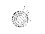
- FIG. 1 is a sectional view of an optical fiber colored core wire according to this embodiment.
- the optical fiber colored core wire 1 includes an optical fiber bare wire 2, a primary layer 3, a secondary layer 4, and a colored layer 5.
- the bare optical fiber 2 is formed of, for example, quartz glass and transmits light.
- the mode field diameter (MFD) of the bare optical fiber 2 is, for example, 8.2 to 9.6 ⁇ m for light having a wavelength of 1310 nm.
- the primary layer 3 is made of a UV curable resin and covers the bare optical fiber 2.
- the secondary layer 4 is formed of a UV curable resin and covers the primary layer 3.
- the colored layer 5 is formed of a colored UV curable resin and is disposed outside the primary layer 3 and the secondary layer 4.
- the specific material of UV curable resin used as the primary layer 3, the secondary layer 4, and the colored layer 5 may mutually be the same, and may differ respectively.
- these UV curable resins for example, acrylate resins can be used.
- FIG. 2 is a diagram illustrating the configuration of an optical fiber ribbon 51 provided with the optical fiber colored core wire 1 of FIG.
- the optical fiber ribbon 51 is formed by connecting a plurality of optical fiber colored cores 1 with connecting portions 115 arranged at intervals. More specifically, a plurality of optical fiber colored core wires 1 are arranged, and adjacent optical fiber colored core wires 1 are connected by a connecting portion 115.
- a direction in which the optical fiber colored core wire 1 extends is referred to as a longitudinal direction
- a direction in which a plurality of optical fiber colored core wires are arranged is referred to as a width direction.
- the width direction is orthogonal to the longitudinal direction.
- the connecting portions 115 are arranged at regular intervals in the longitudinal direction of the optical fiber colored core wire 1.
- 115 is arranged at a position shifted in the longitudinal direction.
- the connection part 115 is arrange
- the optical fiber ribbon 51 By forming the optical fiber ribbon 51 as shown in FIG. 2, the optical fiber ribbon 51 can be rounded into a cylindrical shape or folded. For this reason, the some optical fiber colored core wire 1 can be bundled with high density. Furthermore, the adjacent optical fiber colored core wires 1 are connected by a connecting portion 115 that is spaced apart in the longitudinal direction. For this reason, the specific optical fiber colored core wire 1 can be easily taken out by peeling off some of the connecting portions 115.
- the connecting part 115 is made of a UV curable resin.
- the optical fiber ribbon 51 includes four optical fiber colored cores 1, but the optical fiber ribbon 51 may be formed using five or more optical fiber colored cores 1. Good.
- the optical fiber ribbon 51 can be used for a loose tube cable, a slot type cable, a ribbon type center tube cable, a wrapping tube cable, a micro duct cable, and the like.
- the micro duct cable is a kind of loose tube cable, in which optical fibers are packed in a thin loose tube at high density. Due to such a structure, a relatively strong lateral pressure acts on the optical fiber colored core wire 1 in the loose tube cable, and the light transmission loss may increase due to microbending.
- the secondary layer 4 or the colored layer 5 is formed of a hard material, and the primary layer 3 is formed of a soft material. It is valid. Thus, by softening the primary layer 3 in contact with the bare optical fiber 2 and hardening the secondary layer 4 or the colored layer 5 located outside the primary layer 3, the bare optical fiber 2 can be effectively removed from external force. Can be protected.
- the Young's modulus of the secondary layer 4 or the colored layer 5 is preferably in the range of 700 MPa to 1400 MPa, for example.
- FIG. 3 is a diagram illustrating an example of an optical fiber cable 50 using the optical fiber ribbon 51.
- the optical fiber cable 50 includes a plurality of optical fiber ribbons 51, a binding material 53, a wrapping tube 54, a cylindrical sheath 55, a pair of strength members 56, and a pair of tear strings 57. .
- the binding material 53 bundles the optical fiber ribbons 51.
- the wrapping tube 54 covers the optical fiber ribbon 51 bundled with the binding material 53.
- the sheath 55 covers the optical fiber ribbon 51 together with the wrapping tube 54.
- the pair of strength members 56 are embedded in the sheath 55.
- the pair of tear strings 57 are embedded at positions close to the inner peripheral surface in the sheath 55.
- marker protrusions 58 project from the positions where the pair of tear strings 57 are arranged.
- the marker protrusion 58 is formed along the tear string 57 and indicates a position where the tear string 57 is embedded.
- the optical fiber cable 50 may not include the wrapping tube 54, the tensile body 56, the tear string 57, and the marker protrusion 58. Further, the optical fiber cable 50 may include only one optical fiber ribbon 51.
- a bare wire forming process is first performed.
- the optical fiber bare wire 2 is formed.
- the bare optical fiber 2 is drawn out of, for example, a glass base material heated to about 2000 ° C. and formed to have a desired outer diameter.
- the outer diameter of the bare optical fiber 2 is, for example, about several hundred ⁇ m.
- a primary layer forming step is performed.
- a UV curable resin to be the primary layer 3 is applied around the bare optical fiber 2. Thereafter, the applied UV curable resin is irradiated with UV light and cured to form the primary layer 3.
- a secondary layer forming step is performed.
- a UV curable resin that becomes the secondary layer 4 is applied around the primary layer 3. Thereafter, the applied UV curable resin is irradiated with UV light and cured to form the secondary layer 4. In addition, after applying the UV curable resin that becomes the primary layer 3 around the bare optical fiber 2, the UV curable resin that becomes the secondary layer 4 is continuously applied thereon and irradiated with UV light.
- the primary layer 3 and the secondary layer 4 may be cured together. That is, the primary layer forming step and the secondary layer forming step may be performed simultaneously.
- a colored layer forming step is performed.
- a UV curable resin that becomes the colored layer 5 is applied around the secondary layer 4. Thereafter, the applied UV curable resin is irradiated with UV light and cured to form the colored layer 5. Thereby, the optical fiber colored core wire 1 is obtained.
- a ribbon forming process is performed. In the ribbon forming process, a UV curable resin that becomes the connecting portion 115 is applied to a plurality of optical fiber colored core wires 1 at a plurality of locations at intervals in the longitudinal direction. Thereafter, the applied UV curable resin is cured by irradiating UV light to form the connecting portion 115. Thereby, the some optical fiber colored core wire 1 is mutually connected, and the optical fiber ribbon 51 is obtained.
- the optical fiber cable 50 is obtained by accommodating the optical fiber ribbon 51 in the sheath 55.
- UV light irradiation is performed a plurality of times.
- this inventor discovered that hardening of the primary layer 3 may advance also in the process after a primary layer formation process. Specifically, when the curing of the primary layer 3 in the primary layer forming process is insufficient, the UV light transmitted through the secondary layer 4 and the colored layer 5 is irradiated to the primary layer 3 when the UV light is irradiated in the subsequent process. And the hardening of the primary layer 3 proceeds.
- the Young's modulus of the primary layer 3 becomes hard beyond a desired range, and the light transmission loss may increase due to insufficient effect of the external layer to relax the external force. . Further, due to insufficient curing of the primary layer 3, when water comes into contact with the optical fiber ribbon 51, the primary layer 3 is separated from the bare optical fiber 2 or the primary layer 3 and the bare optical fiber 2. In some cases, a water bubble may be interposed between the two and a side pressure may be applied to the bare optical fiber 2.
- the MFD is 9.1 ⁇ m
- the outer diameter of the bare optical fiber 2 is 125 ⁇ m
- the outer diameter of the primary layer 3 is 190 ⁇ m
- the outer diameter of the secondary layer 4 is 239 ⁇ m in light having a wavelength of 1310 nm.
- the optical fiber colored core wire 1 having an outer diameter of the colored layer 5 of 252 ⁇ m is used.
- the optical fiber colored core wire 1 is compliant with G652D or G657A1 established by, for example, the International Telecommunication Union Telecommunication Standardization Sector (ITU-T).
- the outer diameters of the primary layer 3, the secondary layer 4 and the colored layer 5 described above are design values, and actual dimensions have an error of about ⁇ 3 ⁇ m. Moreover, the said dimension etc. are examples, The result obtained from each example shown in Table 1 is applicable also to the optical fiber colored core wire 1 which changed the dimension and MDF from said value.
- Primary Young's modulus in Table 1 refers to the Young's modulus of the primary layer 3 in each state during the manufacturing process of the optical fiber cable 50.
- “primary Young's modulus before coloring” indicates the Young's modulus of the primary layer 3 after the secondary layer forming step.
- the “primary Young's modulus after coloring” indicates the Young's modulus of the primary layer 3 after the colored layer forming step.
- “Primary Young's modulus after ribbon formation” indicates the Young's modulus of the primary layer 3 after the ribbon forming step.
- the Young's modulus of the primary layer 3 is obtained by measuring the strain by applying a shear stress to the primary layer 3 with the bare optical fiber 2 fixed, and drawing a stress-strain curve.
- the Young's modulus of Example 1 For example, focusing on the primary Young's modulus of Example 1, it is 0.50 MPa before coloring, 0.60 MPa after coloring, and 0.63 MPa after ribboning. As described above, the Young's modulus of the primary layer 3 increases as the process proceeds, meaning that the curing of the primary layer 3 is progressing by the UV light transmitted through the secondary layer 4 and the colored layer 5. To do. This tendency is common to Examples 1 to 6 and Comparative Examples 1 to 5.
- the degree of curing is shown together with the value of each primary Young's modulus.
- the degree of cure is the ratio of the primary Young's modulus to the numerical value of the saturated primary Young's modulus described later.
- the primary Young's modulus before coloring in Example 1 is 0.50 MPa
- the saturated primary Young's modulus is 0.70 MPa.
- the degree of curing before coloring in Example 1 can be calculated as 0.50 ⁇ 0.70 ⁇ 0.71 (71%). Therefore, in the column of “primary Young's modulus before coloring” in Example 1, a value of 71% indicating the degree of cure is written together with a value of 0.50 MPa.
- “Saturated primary Young's modulus” in Table 1 indicates the saturated Young's modulus of the primary layer 3. More specifically, in a state where the UV curable resin that becomes the primary layer 3 is applied to the bare optical fiber 2, UV light including a wavelength that contributes to the curing reaction is sufficient for the primary layer 3 to completely cure. It means the Young's modulus of the primary layer 3 when only irradiation is performed. For example, in this embodiment, when UV light having a central wavelength of about 365 nm is irradiated to the UV curable resin to be the primary layer 3 at 1 J / cm 2 , the Young layer of the primary layer 3 can be irradiated even if UV light is further irradiated. The rate did not increase.
- This state is defined as a state in which the primary layer 3 is completely cured. Moreover, since the above-mentioned “curing degree” is calculated based on the saturated Young's modulus, it is an index indicating how much the primary layer 3 is cured in each state.
- the “microbend characteristics” in Table 1 indicates the stability of light transmission with respect to the lateral pressure of the optical fiber colored core wire 1. Specifically, in IEC-TR62221 Method-B, the magnitude of the transmission loss of light transmitted through the bare optical fiber 2 under the conditions of tension 1N, sandpaper # 360, length 600 m, bobbin size ⁇ 400 mm It is measured.
- “Cable characteristics” in Table 1 shows the result of measuring the magnitude of light transmission loss when an optical fiber cable is prepared using the optical fiber ribbon 51. Specifically, the result of changing the ambient temperature in the range of ⁇ 40 ° C. to + 85 ° C. in the optical fiber cable having 864 optical fiber colored cores 1 is shown. As a result, if the transmission loss of light with a wavelength of 1550 nm is 0.15 dB / km or less, it is OK (good), and if it is larger, it is NG (bad). In addition, when the numerical value of the above-mentioned micro bend characteristic is large, since the transmission loss of light tends to increase by applying a side pressure to the optical fiber colored core wire 1, the cable characteristic is also likely to deteriorate. For example, in Comparative Example 2, the value of “microbend characteristics in the ribbon state” is 0.40 dB / km, which is the largest in Table 1, and the test result of “cable characteristics” is also poor.
- the “ribbon 60 ° C. hot water immersion test” in Table 1 shows the stability of the optical fiber ribbon 51 to water. Specifically, an optical fiber ribbon 51 having 12 optical fiber colored cores 1 was immersed in warm water at 60 ° C. for one month. If the transmission loss of light having a wavelength of 1550 nm is 0.05 dB / km or less in an immersed state or after being taken out from warm water, it is OK (good), and if it is larger, it is NG (bad).
- Example 3 in which the value of the primary Young's modulus after ribbon formation is relatively large.
- the test result of the cable characteristics is good.
- the primary Young's modulus after ribbon formation is 0.73 MPa, and in Comparative Example 1 which is the second largest after Example 3, the test result of the cable characteristics is poor. From this result, the primary Young's modulus after ribbon formation is preferably 0.72 MPa or less.
- Example 4 attention is focused on Example 4 and Comparative Example 5 in which the value of the primary Young's modulus after ribbon formation is relatively small.
- Example 4 in which the primary Young's modulus after ribbon formation is 0.20 MPa, the test result of the cable characteristics is good.
- Comparative Example 5 where the primary Young's modulus after ribbon formation is 0.17 MPa, which is the second smallest after Example 4, the test result of the cable characteristics is poor.
- the primary Young's modulus after ribbon formation is preferably 0.20 MPa or more. From the above consideration, the primary Young's modulus after ribbon formation is preferably in the range of 0.20 MPa to 0.72 MPa.
- the optimum numerical range of the ratio of the primary Young's modulus after ribbon formation to the saturated primary Young's modulus (hereinafter simply referred to as “degree of hardening after ribbon formation”) will be considered.
- degree of curing after ribbon formation When the degree of curing after ribbon formation is low, when the ribbon 60 ° C. hot water immersion test is performed, the primary layer 3 is peeled off from the bare optical fiber 2 due to water coming into contact with the optical fiber ribbon 51, and the light transmission loss increases. . Therefore, the optimum numerical range of the degree of cure after ribbon formation can be judged from the result of the ribbon 60 ° C. hot water immersion test.
- Example 2 In Table 1, attention is paid to Example 2 and Comparative Example 3 in which the value of the degree of cure after ribbon formation is relatively small. In Example 2 where the degree of cure after ribbon formation is 75%, the result of the ribbon 60 ° C. hot water immersion test is good. On the other hand, the result of the ribbon 60 ° C. hot water immersion test of Comparative Example 3 in which the degree of cure after ribbon formation is 73%, which is the second smallest after Example 2, is poor. From this result, it is preferable that the degree of cure after ribbon formation is 75% or more. In Table 1, the maximum value of the degree of cure after ribbon formation is 97% of Example 5, but when the degree of cure after ribbon formation is greater than 97%, the primary layer 3 peels off from the bare optical fiber 2. It is thought that it can be suppressed more reliably. Therefore, the degree of cure after ribbon formation may be greater than 97%.
- the Young's modulus of the primary layer 3 in a state where the plurality of optical fiber colored cores 1 are connected to form the optical fiber ribbon 51 is 75% or more with respect to the saturation Young's modulus of the primary layer 3. It is preferable to do. By doing so, the degree of cure of the primary layer 3 in the state of the optical fiber ribbon 51 reaches a level sufficient to satisfy the characteristics of the optical fiber ribbon 51. Thereby, when the optical fiber ribbon 51 contacts with water, it can suppress that the primary layer 3 peels from the optical fiber bare wire 2. FIG. Therefore, an increase in light transmission loss caused by contact of the optical fiber ribbon 51 with water can be suppressed and reliability can be ensured.
- the primary layer 3 is formed of a material having a saturation Young's modulus of 0.88 MPa or less, even if the primary layer 3 is hardened after the primary layer forming step, the primary layer 3 is formed of the optical fiber ribbon 51. Soft enough to meet the properties. Therefore, the external force transmitted to the bare optical fiber 2 can be relaxed and the anti-microbend characteristics can be ensured.
- the Young's modulus of the primary layer 3 in the state of the optical fiber ribbon 51 is set to 0.72 MPa or less, the transmission loss of light that occurs when a side pressure is applied to the optical fiber colored core wire 1 is suppressed, and Microbend characteristics can be ensured.
- the Young's modulus is set to 0.20 MPa or more, it is possible to suppress the relaxation of the external force applied to the bare optical fiber 2 due to the excessively soft primary layer 3.
- the primary layer 3 and the bare optical fiber 2 can be protected from external force or impact.
- the optical fiber cable 50 is preferably manufactured using the optical fiber ribbon 51 whose primary layer 3 has a degree of curing after ribbonization of 75% or more. Thereby, for example, even when water enters the sheath 55, the primary layer 3 can be prevented from peeling from the bare optical fiber 2, and the reliability of the optical fiber cable 50 can be secured.
- the colored layer 5 also serves as the secondary layer 4 so that the primary layer 3 and the colored layer 5 are adjacent to each other. You may do it.
- the primary Young's modulus before coloring refers to the Young's modulus of the primary layer 3 after the primary layer forming step.
- the connecting portions 115 are arranged in a staggered manner as shown in FIG. 2, but the present invention is not limited to this.
- the connecting portions 115 may not be arranged in a staggered manner, and the connecting portions 115 may integrally cover the plurality of optical fiber colored core wires 1.
Landscapes
- Physics & Mathematics (AREA)
- General Physics & Mathematics (AREA)
- Optics & Photonics (AREA)
- Engineering & Computer Science (AREA)
- Manufacturing & Machinery (AREA)
- Chemical & Material Sciences (AREA)
- Life Sciences & Earth Sciences (AREA)
- Chemical Kinetics & Catalysis (AREA)
- General Life Sciences & Earth Sciences (AREA)
- General Chemical & Material Sciences (AREA)
- Geochemistry & Mineralogy (AREA)
- Materials Engineering (AREA)
- Organic Chemistry (AREA)
- Optical Fibers, Optical Fiber Cores, And Optical Fiber Bundles (AREA)
- Decoration Of Textiles (AREA)
- Sewing Machines And Sewing (AREA)
- Ropes Or Cables (AREA)
Abstract
Description
本願は、2016年9月30日に、日本に出願された特願2016-194548号に基づき優先権を主張し、その内容をここに援用する。
図1は、本実施形態に係る光ファイバ着色心線の断面図である。図1に示すように、光ファイバ着色心線1は、光ファイバ裸線2と、プライマリ層3と、セカンダリ層4と、着色層5と、を備えている。
なお、プライマリ層3、セカンダリ層4、および着色層5となるUV硬化型樹脂の具体的な材質は互いに同じであってもよく、それぞれ異なっていてもよい。これらのUV硬化型樹脂としては、例えばアクリレート樹脂などを用いることができる。
連結部115は、UV硬化型樹脂により形成されている。なお、図2の例では、光ファイバリボン51は4本の光ファイバ着色心線1を備えているが、5本以上の光ファイバ着色心線1を用いて光ファイバリボン51を形成してもよい。
次に、プライマリ層形成工程が行われる。プライマリ層形成工程では、光ファイバ裸線2の周囲に、プライマリ層3となるUV硬化型樹脂を塗布する。その後、塗布したUV硬化型樹脂にUV光を照射して硬化させ、プライマリ層3を形成する。
次に、セカンダリ層形成工程が行われる。セカンダリ層形成工程では、プライマリ層3の周囲にセカンダリ層4となるUV硬化型樹脂を塗布する。その後、塗布したUV硬化型樹脂にUV光を照射して硬化させ、セカンダリ層4を形成する。なお、光ファイバ裸線2の周囲にプライマリ層3となるUV硬化型樹脂を塗布後、その上にセカンダリ層4となるUV硬化型樹脂を続けて塗布し、これにUV光を照射することでプライマリ層3およびセカンダリ層4をまとめて硬化させてもよい。つまり、プライマリ層形成工程およびセカンダリ層形成工程は同時に行われてもよい。
次に、リボン形成工程が行われる。リボン形成工程では、複数の光ファイバ着色心線1に、連結部115となるUV硬化型樹脂を長手方向に間隔を空けて複数個所に塗布する。その後、塗布したUV硬化型樹脂にUV光を照射して硬化させ、連結部115を形成する。これにより、複数の光ファイバ着色心線1が互いに連結されて光ファイバリボン51が得られる。
次に、光ファイバリボン51をシース55の内部に収容することで、光ファイバケーブル50が得られる。
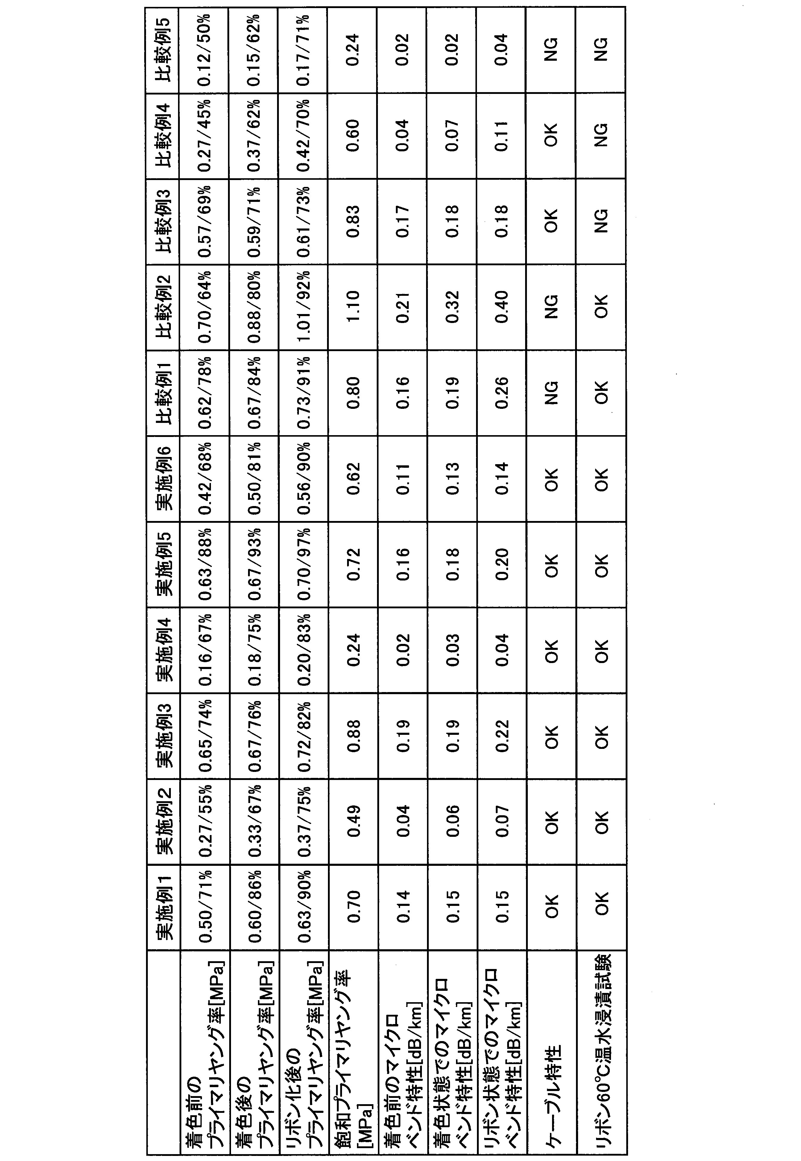
表1の「プライマリヤング率」とは、光ファイバケーブル50の製造工程中の各状態におけるプライマリ層3のヤング率をいう。例えば、「着色前のプライマリヤング率」は、セカンダリ層形成工程後におけるプライマリ層3のヤング率を示す。また、「着色後のプライマリヤング率」は、着色層形成工程後におけるプライマリ層3のヤング率を示す。また、「リボン化後のプライマリヤング率」は、リボン形成工程後におけるプライマリ層3のヤング率を示す。
上記プライマリ層3のヤング率は、光ファイバ裸線2を固定した状態でプライマリ層3に対してせん断応力を与えてひずみを測定し、応力-ひずみ曲線を描くことで求められる。
なお、先述のマイクロベンド特性の数値が大きい場合、光ファイバ着色心線1に側圧が印加することで光の伝達損失が増大しやすいため、ケーブル特性も低下しやすい。例えば、比較例2は「リボン状態でのマイクロベンド特性」の数値が0.40dB/kmであり表1中で最も大きく、「ケーブル特性」の試験結果も不良となっている。
次に、リボン化後のプライマリヤング率の最適な数値範囲について考察する。
リボン化後のプライマリヤング率が高い場合は、ケーブル化して光ファイバ着色心線1に外力が加わった場合に、光ファイバ裸線2に加わる外力の緩和が不充分となり、光の伝達損失が増加する。また、リボン化後のプライマリヤング率が過剰に低い場合も、外力を受けたプライマリ層3が大きく変形することで、光ファイバ裸線2に加わる外力の緩和が不充分となり、光の伝達損失が増加する。従って、リボン化後のプライマリヤング率の最適な数値範囲は、ケーブル特性の試験結果から判断することができる。
以上の考察により、リボン化後のプライマリヤング率は0.20MPa以上0.72MPa以下の範囲であることが好ましい。
次に、リボン化後のプライマリヤング率の飽和プライマリヤング率に対する割合(以下、単に「リボン化後硬化度」という)の最適な数値範囲について考察する。
リボン化後硬化度が低い場合、リボン60℃温水浸漬試験の実施時に、水が光ファイバリボン51に接触することでプライマリ層3が光ファイバ裸線2から剥離し、光の伝達損失が大きくなる。従って、リボン化後硬化度の最適な数値範囲は、リボン60℃温水浸漬試験の結果から判断することができる。
なお、表1におけるリボン化後硬化度の最大値は実施例5の97%であるが、リボン化後硬化度が97%より大きい場合、プライマリ層3が光ファイバ裸線2から剥離するのをより確実に抑えられると考えられる。従って、リボン化後硬化度は97%より大きくてもよい。
次に、飽和プライマリヤング率の最適な数値範囲について考察する。
表1の比較例2に着目すると、リボン化後硬化度が92%であり、比較的大きいにもかかわらず、ケーブル特性が不良となっている。これは、飽和プライマリヤング率が1.10MPaであり比較的大きく、硬い材質をプライマリ層3として用いているためであると考えられる。
ここで、表1のうち、飽和プライマリヤング率が比較例2の次に大きいのは、実施例3の0.88MPaであり、実施例3のケーブル特性は良好となっている。
この結果から、プライマリ層3の飽和ヤング率は0.88MPa以下であることが好ましい。
Claims (8)
- 複数の光ファイバ着色心線同士を、UV硬化型樹脂により形成された連結部で互いに連結してなる光ファイバリボンであって、
前記光ファイバ着色心線はそれぞれ、
光ファイバ裸線と、
前記光ファイバ裸線を覆うUV硬化型樹脂により形成されたプライマリ層と、
前記プライマリ層を覆うUV硬化型樹脂により形成されたセカンダリ層と、
前記セカンダリ層の外側に配置され、着色されたUV硬化型樹脂により形成された着色層と、を備え、
前記プライマリ層のヤング率が、前記プライマリ層の飽和ヤング率に対して75%以上である、光ファイバリボン。 - 前記プライマリ層の飽和ヤング率が0.88MPa以下である、請求項1に記載の光ファイバリボン。
- 前記プライマリ層のヤング率が、0.20MPa以上0.72MPa以下である、請求項1または2に記載の光ファイバリボン。
- 前記着色層のヤング率が700MPa以上1400MPa以下である、請求項1から3のいずれか1項に記載の光ファイバリボン。
- 前記セカンダリ層のヤング率が、700MPa以上1400MPa以下である、請求項1から3のいずれか1項に記載の光ファイバリボン。
- 請求項1から請求項5のいずれか1項に記載の光ファイバリボンと、
前記光ファイバリボンを内部に収容するシースと、を備える光ファイバケーブル。 - 光ファイバ裸線を形成する裸線形成工程と、
前記光ファイバ裸線の周囲にUV硬化型樹脂を塗布し、UV光を照射してプライマリ層を形成するプライマリ層形成工程と、
前記プライマリ層の周囲にUV硬化型樹脂を塗布し、UV光を照射して着色層を形成する着色層形成工程と、
前記裸線形成工程、前記プライマリ層形成工程、および前記着色層形成工程を経て形成された複数の光ファイバ着色心線にUV硬化型樹脂を塗布し、UV光を照射して当該UV硬化型樹脂を硬化させることで複数の前記光ファイバ着色心線同士を連結し、光ファイバリボンを形成するリボン形成工程と、を有し、
前記リボン形成工程後の前記プライマリ層のヤング率が、前記プライマリ層の飽和ヤング率に対して75%以上である、光ファイバリボンの製造方法。 - 複数の光ファイバ着色心線同士を、UV硬化型樹脂により形成された連結部で互いに連結してなる光ファイバリボンであって、
前記光ファイバ着色心線はそれぞれ、
光ファイバ裸線と、
前記光ファイバ裸線を覆うUV硬化型樹脂により形成されたプライマリ層と、
前記プライマリ層の外側に配置され、着色されたUV硬化型樹脂により形成された着色層と、を備え、
前記プライマリ層のヤング率が、前記プライマリ層の飽和ヤング率に対して75%以上である、光ファイバリボン。
Priority Applications (8)
| Application Number | Priority Date | Filing Date | Title |
|---|---|---|---|
| JP2018542839A JP6841837B2 (ja) | 2016-09-30 | 2017-09-28 | 光ファイバリボンの製造方法および光ファイバケーブルの製造方法 |
| US16/337,873 US10908373B2 (en) | 2016-09-30 | 2017-09-28 | Optical fiber ribbon, optical fiber cable, and method of manufacturing optical fiber ribbon |
| EP17856314.4A EP3521884B1 (en) | 2016-09-30 | 2017-09-28 | Optical fiber ribbon, optical fiber cable, and method for manufacturing optical fiber ribbon |
| AU2017338242A AU2017338242A1 (en) | 2016-09-30 | 2017-09-28 | Optical fiber ribbon, optical fiber cable, and method for manufacturing optical fiber ribbon |
| CN201780058307.9A CN109716195A (zh) | 2016-09-30 | 2017-09-28 | 光纤带、光缆以及光纤带的制造方法 |
| CA3038637A CA3038637C (en) | 2016-09-30 | 2017-09-28 | Optical fiber ribbon, optical fiber cable, and method of manufacturing optical fiber ribbon |
| ES17856314T ES2939041T3 (es) | 2016-09-30 | 2017-09-28 | Cinta de fibra óptica, cable de fibra óptica y procedimiento para fabricar cinta de fibra óptica |
| KR1020197008860A KR102326802B1 (ko) | 2016-09-30 | 2017-09-28 | 광섬유 리본, 광섬유 케이블, 및 광섬유 리본의 제조 방법 |
Applications Claiming Priority (2)
| Application Number | Priority Date | Filing Date | Title |
|---|---|---|---|
| JP2016-194548 | 2016-09-30 | ||
| JP2016194548 | 2016-09-30 |
Publications (1)
| Publication Number | Publication Date |
|---|---|
| WO2018062365A1 true WO2018062365A1 (ja) | 2018-04-05 |
Family
ID=61762835
Family Applications (1)
| Application Number | Title | Priority Date | Filing Date |
|---|---|---|---|
| PCT/JP2017/035147 Ceased WO2018062365A1 (ja) | 2016-09-30 | 2017-09-28 | 光ファイバリボン、光ファイバケーブル、および光ファイバリボンの製造方法 |
Country Status (9)
| Country | Link |
|---|---|
| US (1) | US10908373B2 (ja) |
| EP (1) | EP3521884B1 (ja) |
| JP (1) | JP6841837B2 (ja) |
| KR (1) | KR102326802B1 (ja) |
| CN (1) | CN109716195A (ja) |
| AU (1) | AU2017338242A1 (ja) |
| CA (1) | CA3038637C (ja) |
| ES (1) | ES2939041T3 (ja) |
| WO (1) | WO2018062365A1 (ja) |
Cited By (7)
| Publication number | Priority date | Publication date | Assignee | Title |
|---|---|---|---|---|
| JP2021189231A (ja) * | 2020-05-27 | 2021-12-13 | 古河電気工業株式会社 | 光ファイバ心線、光ファイバテープ心線及び光ファイバケーブル |
| WO2022092089A1 (ja) * | 2020-10-29 | 2022-05-05 | 古河電気工業株式会社 | 光ファイバ着色心線、光ファイバリボン、単心ファイバの集合体ケーブル、リボンケーブルおよびこれらの製造方法 |
| JPWO2022191097A1 (ja) * | 2021-03-10 | 2022-09-15 | ||
| EP3796060B1 (en) | 2018-10-11 | 2022-12-28 | Fujikura Ltd. | Optical fiber cable |
| WO2023113012A1 (ja) * | 2021-12-17 | 2023-06-22 | 住友電気工業株式会社 | 光ファイバケーブル |
| WO2023210505A1 (ja) * | 2022-04-26 | 2023-11-02 | 株式会社フジクラ | 光ファイバ素線、および光ファイバリボンの製造方法 |
| TWI923900B (zh) | 2022-04-26 | 2026-05-01 | 日商藤倉股份有限公司 | 光纖素線、及光纖帶之製造方法 |
Families Citing this family (5)
| Publication number | Priority date | Publication date | Assignee | Title |
|---|---|---|---|---|
| WO2018062365A1 (ja) | 2016-09-30 | 2018-04-05 | 株式会社フジクラ | 光ファイバリボン、光ファイバケーブル、および光ファイバリボンの製造方法 |
| CA3038632C (en) | 2016-09-30 | 2021-05-18 | Fujikura Ltd. | Optical fiber colored core wire, optical fiber cable, and method of manufacturing optical fiber colored core wire |
| CN113979648A (zh) * | 2021-12-24 | 2022-01-28 | 南京华信藤仓光通信有限公司 | 一种光模块用光纤带的制造方法 |
| KR102676816B1 (ko) * | 2022-12-23 | 2024-06-19 | 엘에스전선 주식회사 | 광섬유 리본 |
| WO2024210481A2 (ko) * | 2023-04-06 | 2024-10-10 | 엘에스전선 주식회사 | 롤러블 광섬유 리본 및 이를 포함하는 광케이블 |
Citations (13)
| Publication number | Priority date | Publication date | Assignee | Title |
|---|---|---|---|---|
| JPS62202842A (ja) * | 1986-03-03 | 1987-09-07 | Nippon Telegr & Teleph Corp <Ntt> | 紫外線硬化樹脂被覆光フアイバの高速被覆方法 |
| JPH0769686A (ja) * | 1993-08-31 | 1995-03-14 | Dainippon Ink & Chem Inc | 光ファイバ被覆用紫外線硬化型樹脂組成物 |
| JP2005321420A (ja) | 2004-04-07 | 2005-11-17 | Hitachi Cable Ltd | 光ファイバテープユニット及び光ファイバケーブル |
| JP2006053346A (ja) | 2004-08-11 | 2006-02-23 | Furukawa Electric Co Ltd:The | 光ファイバ素線及び光ファイバテープ心線 |
| JP2011128377A (ja) * | 2009-12-17 | 2011-06-30 | Furukawa Electric Co Ltd:The | 光ファイバ心線 |
| US20110274397A1 (en) * | 2010-05-05 | 2011-11-10 | Ofs Fitel, Llc | Tight-buffered optical fiber having improved fiber access |
| JP2012234122A (ja) * | 2011-05-09 | 2012-11-29 | Fujikura Ltd | 光ユニット |
| US20130129288A1 (en) | 2011-11-17 | 2013-05-23 | Sumitomo Electric Industries, Ltd. | Optical cable |
| JP2013134477A (ja) | 2011-12-27 | 2013-07-08 | Furukawa Electric Co Ltd:The | 光ファイバ着色心線、光ファイバテープ心線および光ファイバケーブル |
| JP2015086087A (ja) * | 2013-10-29 | 2015-05-07 | 古河電気工業株式会社 | オーバーコート心線及び当該オーバーコート心線を備えた光ファイバケーブル |
| JP2016194548A (ja) | 2015-03-31 | 2016-11-17 | 株式会社ジェイエスピー | 光反射シート |
| WO2017094560A1 (ja) | 2015-12-01 | 2017-06-08 | 古河電気工業株式会社 | 光ファイバテープ心線及び光ファイバケーブル |
| EP3521884A1 (en) | 2016-09-30 | 2019-08-07 | Fujikura Ltd. | Optical fiber ribbon, optical fiber cable, and method for manufacturing optical fiber ribbon |
Family Cites Families (26)
| Publication number | Priority date | Publication date | Assignee | Title |
|---|---|---|---|---|
| JPH01212255A (ja) | 1988-02-19 | 1989-08-25 | Fujikura Ltd | 光ファイバの被覆方法および被覆装置 |
| JPH04338139A (ja) | 1991-05-14 | 1992-11-25 | Furukawa Electric Co Ltd:The | 光ファイバ素線の製造方法 |
| JPH0560953A (ja) * | 1991-09-03 | 1993-03-12 | Sumitomo Electric Ind Ltd | 光伝送用ガラスフアイバ |
| JPH07267687A (ja) | 1994-03-31 | 1995-10-17 | Fujikura Ltd | 光ファイバの被覆方法 |
| JP2928723B2 (ja) | 1994-04-15 | 1999-08-03 | 株式会社フジクラ | 光ファイバの製法 |
| JPH092844A (ja) | 1995-06-16 | 1997-01-07 | Fujikura Ltd | 光ファイバ素線の製法 |
| US6553169B2 (en) * | 2000-11-29 | 2003-04-22 | Corning Incorporated | Optical fiber coating compositions and coated optical fibers |
| TWI241281B (en) * | 2001-02-20 | 2005-10-11 | Sumitomo Electric Industries | Coated optical fiber, core and optical fiber unit using same |
| KR100960185B1 (ko) * | 2002-05-28 | 2010-05-27 | 스미토모 덴키 고교 가부시키가이샤 | 광파이버 테이프 코어 |
| JP2004012679A (ja) | 2002-06-05 | 2004-01-15 | Fujikura Ltd | 視認性細径光ファイバ素線 |
| US6804442B1 (en) * | 2002-06-07 | 2004-10-12 | Fujikura Ltd. | Optical fiber and optical fiber cable having a first jacket layer and a second jacket layer and a coefficient of thermal expansion selecting method |
| EP1596234A4 (en) | 2003-02-20 | 2006-03-22 | Sumitomo Electric Industries | COATED OPTICAL FIBER AND COATED OPTICAL FIBER WITH CONNECTOR |
| JP2005162522A (ja) | 2003-12-01 | 2005-06-23 | Sumitomo Electric Ind Ltd | 被覆線条体の製造方法、及び被覆線条体製造装置 |
| JP2006084770A (ja) | 2004-09-16 | 2006-03-30 | Hitachi Cable Ltd | 着色被覆光ファイバ心線及びその製造方法 |
| JP2006113448A (ja) | 2004-10-18 | 2006-04-27 | Hitachi Cable Ltd | 光ファイバ心線及びその製造方法 |
| JP2007333795A (ja) * | 2006-06-12 | 2007-12-27 | Furukawa Electric Co Ltd:The | 光ファイバ心線及びその製造方法 |
| JP5041450B2 (ja) * | 2010-11-24 | 2012-10-03 | 古河電気工業株式会社 | 光ファイバ着色心線 |
| JP5417406B2 (ja) | 2011-10-12 | 2014-02-12 | 株式会社フジクラ | 光ファイバ素線の製造方法 |
| JP5564026B2 (ja) | 2011-10-18 | 2014-07-30 | 株式会社フジクラ | 光ファイバテープ心線及びその光ファイバテープ心線を収納した光ファイバケーブル |
| JP5294357B2 (ja) * | 2012-02-15 | 2013-09-18 | 古河電気工業株式会社 | 光ファイバ着色心線、光ファイバテープ心線及び光ファイバケーブル |
| JP5465741B2 (ja) * | 2012-02-17 | 2014-04-09 | 古河電気工業株式会社 | 光ファイバ心線、光ファイバテープ心線および光ケーブル |
| US9678247B2 (en) * | 2012-05-08 | 2017-06-13 | Corning Incorporated | Primary optical fiber coating composition containing non-radiation curable component |
| JP5790942B2 (ja) * | 2012-06-22 | 2015-10-07 | 住友電気工業株式会社 | 光ファイバ素線 |
| JP6106253B1 (ja) * | 2015-12-04 | 2017-03-29 | 株式会社フジクラ | 光ファイバテープ、光ファイバテープの製造方法、及び間欠固定型光ファイバテープの連結部の形成に用いられる紫外線硬化樹脂組成物 |
| CA3038632C (en) * | 2016-09-30 | 2021-05-18 | Fujikura Ltd. | Optical fiber colored core wire, optical fiber cable, and method of manufacturing optical fiber colored core wire |
| RU2759664C1 (ru) * | 2018-01-15 | 2021-11-16 | Призмиан С.П.А. | Способ изготовления гибкой волоконно-оптической ленты и лента |
-
2017
- 2017-09-28 WO PCT/JP2017/035147 patent/WO2018062365A1/ja not_active Ceased
- 2017-09-28 ES ES17856314T patent/ES2939041T3/es active Active
- 2017-09-28 EP EP17856314.4A patent/EP3521884B1/en active Active
- 2017-09-28 JP JP2018542839A patent/JP6841837B2/ja active Active
- 2017-09-28 AU AU2017338242A patent/AU2017338242A1/en not_active Abandoned
- 2017-09-28 US US16/337,873 patent/US10908373B2/en active Active
- 2017-09-28 CA CA3038637A patent/CA3038637C/en active Active
- 2017-09-28 CN CN201780058307.9A patent/CN109716195A/zh active Pending
- 2017-09-28 KR KR1020197008860A patent/KR102326802B1/ko active Active
Patent Citations (24)
| Publication number | Priority date | Publication date | Assignee | Title |
|---|---|---|---|---|
| JPS62202842A (ja) * | 1986-03-03 | 1987-09-07 | Nippon Telegr & Teleph Corp <Ntt> | 紫外線硬化樹脂被覆光フアイバの高速被覆方法 |
| JPH0769686A (ja) * | 1993-08-31 | 1995-03-14 | Dainippon Ink & Chem Inc | 光ファイバ被覆用紫外線硬化型樹脂組成物 |
| JP2005321420A (ja) | 2004-04-07 | 2005-11-17 | Hitachi Cable Ltd | 光ファイバテープユニット及び光ファイバケーブル |
| JP4412040B2 (ja) | 2004-04-07 | 2010-02-10 | 日立電線株式会社 | 光ファイバテープユニット及び光ファイバケーブル |
| JP2006053346A (ja) | 2004-08-11 | 2006-02-23 | Furukawa Electric Co Ltd:The | 光ファイバ素線及び光ファイバテープ心線 |
| JP2011128377A (ja) * | 2009-12-17 | 2011-06-30 | Furukawa Electric Co Ltd:The | 光ファイバ心線 |
| US20110274397A1 (en) * | 2010-05-05 | 2011-11-10 | Ofs Fitel, Llc | Tight-buffered optical fiber having improved fiber access |
| JP2012234122A (ja) * | 2011-05-09 | 2012-11-29 | Fujikura Ltd | 光ユニット |
| US8989543B2 (en) | 2011-11-17 | 2015-03-24 | Sumitomo Electric Industries, Ltd. | Optical cable |
| CN103123409A (zh) | 2011-11-17 | 2013-05-29 | 住友电气工业株式会社 | 光缆 |
| TW201326932A (zh) | 2011-11-17 | 2013-07-01 | Sumitomo Electric Industries | 光纜 |
| US20130129288A1 (en) | 2011-11-17 | 2013-05-23 | Sumitomo Electric Industries, Ltd. | Optical cable |
| JP2013134477A (ja) | 2011-12-27 | 2013-07-08 | Furukawa Electric Co Ltd:The | 光ファイバ着色心線、光ファイバテープ心線および光ファイバケーブル |
| JP2015086087A (ja) * | 2013-10-29 | 2015-05-07 | 古河電気工業株式会社 | オーバーコート心線及び当該オーバーコート心線を備えた光ファイバケーブル |
| JP2016194548A (ja) | 2015-03-31 | 2016-11-17 | 株式会社ジェイエスピー | 光反射シート |
| WO2017094560A1 (ja) | 2015-12-01 | 2017-06-08 | 古河電気工業株式会社 | 光ファイバテープ心線及び光ファイバケーブル |
| TW201723536A (zh) | 2015-12-01 | 2017-07-01 | Furukawa Electric Co Ltd | 光纖帶芯線及光纖纜線 |
| CN108369324A (zh) | 2015-12-01 | 2018-08-03 | 古河电气工业株式会社 | 光纤带芯线和光纤线缆 |
| US20180273427A1 (en) | 2015-12-01 | 2018-09-27 | Furukawa Electric Co., Ltd. | Optical Fiber Ribbon And Optical Fiber Cable |
| EP3385765A1 (en) | 2015-12-01 | 2018-10-10 | Furukawa Electric Co. Ltd. | Optical fiber ribbon core-wire and optical fiber cable |
| JP6490805B2 (ja) | 2015-12-01 | 2019-03-27 | 古河電気工業株式会社 | 光ファイバテープ心線及び光ファイバケーブル |
| TWI666471B (zh) | 2015-12-01 | 2019-07-21 | 日商古河電氣工業股份有限公司 | 光纖帶芯線及光纖纜線 |
| US10882783B2 (en) | 2015-12-01 | 2021-01-05 | Furukawa Electric Co., Ltd. | Optical fiber ribbon and optical fiber cable |
| EP3521884A1 (en) | 2016-09-30 | 2019-08-07 | Fujikura Ltd. | Optical fiber ribbon, optical fiber cable, and method for manufacturing optical fiber ribbon |
Non-Patent Citations (1)
| Title |
|---|
| See also references of EP3521884A4 |
Cited By (12)
| Publication number | Priority date | Publication date | Assignee | Title |
|---|---|---|---|---|
| EP3796060B1 (en) | 2018-10-11 | 2022-12-28 | Fujikura Ltd. | Optical fiber cable |
| US12105335B2 (en) | 2018-10-11 | 2024-10-01 | Afl Telecommunications Llc | Optical fiber cable |
| JP2021189231A (ja) * | 2020-05-27 | 2021-12-13 | 古河電気工業株式会社 | 光ファイバ心線、光ファイバテープ心線及び光ファイバケーブル |
| WO2022092089A1 (ja) * | 2020-10-29 | 2022-05-05 | 古河電気工業株式会社 | 光ファイバ着色心線、光ファイバリボン、単心ファイバの集合体ケーブル、リボンケーブルおよびこれらの製造方法 |
| JPWO2022092089A1 (ja) * | 2020-10-29 | 2022-05-05 | ||
| JP7688041B2 (ja) | 2020-10-29 | 2025-06-03 | 古河電気工業株式会社 | 光ファイバ着色心線、光ファイバリボン、単心ファイバの集合体ケーブル、リボンケーブルおよびこれらの製造方法 |
| JPWO2022191097A1 (ja) * | 2021-03-10 | 2022-09-15 | ||
| WO2022191097A1 (ja) | 2021-03-10 | 2022-09-15 | 古河電気工業株式会社 | 光ファイバ着色心線、光ファイバリボン、単心ファイバの集合体ケーブル、光ファイバリボンケーブル、およびこれらの製造方法 |
| US12554089B2 (en) | 2021-03-10 | 2026-02-17 | Furukawa Electric Co., Ltd. | Colored optical fiber, optical fiber ribbon, assembly cable of single fibers, optical fiber ribbon cable and method for manufacturing the same |
| WO2023113012A1 (ja) * | 2021-12-17 | 2023-06-22 | 住友電気工業株式会社 | 光ファイバケーブル |
| WO2023210505A1 (ja) * | 2022-04-26 | 2023-11-02 | 株式会社フジクラ | 光ファイバ素線、および光ファイバリボンの製造方法 |
| TWI923900B (zh) | 2022-04-26 | 2026-05-01 | 日商藤倉股份有限公司 | 光纖素線、及光纖帶之製造方法 |
Also Published As
| Publication number | Publication date |
|---|---|
| KR20190043580A (ko) | 2019-04-26 |
| CA3038637A1 (en) | 2018-04-05 |
| JP6841837B2 (ja) | 2021-03-10 |
| EP3521884A1 (en) | 2019-08-07 |
| US10908373B2 (en) | 2021-02-02 |
| ES2939041T3 (es) | 2023-04-18 |
| EP3521884A4 (en) | 2020-05-13 |
| CN109716195A (zh) | 2019-05-03 |
| AU2017338242A1 (en) | 2019-04-18 |
| EP3521884B1 (en) | 2023-01-18 |
| JPWO2018062365A1 (ja) | 2019-03-07 |
| KR102326802B1 (ko) | 2021-11-15 |
| CA3038637C (en) | 2021-05-04 |
| US20200026013A1 (en) | 2020-01-23 |
Similar Documents
| Publication | Publication Date | Title |
|---|---|---|
| JP6841837B2 (ja) | 光ファイバリボンの製造方法および光ファイバケーブルの製造方法 | |
| JP6841836B2 (ja) | 光ファイバ着色心線の製造方法および光ファイバケーブルの製造方法 | |
| JP7052727B2 (ja) | 間欠連結型光ファイバテープ心線、その製造方法、光ファイバケーブルおよび光ファイバコード | |
| CN102057309B (zh) | 光纤缆线以及光纤带 | |
| JP4619424B2 (ja) | 光ファイバケーブル | |
| JP6273847B2 (ja) | 光ファイバおよび光ケーブル | |
| EP2799920A1 (en) | Multicore optical fiber | |
| US11415769B2 (en) | Intermittent connection-type optical fiber tape core wire, optical fiber cable, and method for manufacturing intermittent connection-type optical fiber tape core wire | |
| WO2017175414A1 (ja) | 光ファイバテープの製造方法、光ファイバテープ及び光ケーブル | |
| JP2011232733A (ja) | 光ファイバテープ心線、光ファイバケーブル、及び光ファイバテープ心線の製造方法 | |
| JPH09113773A (ja) | 光ファイバテープ心線 | |
| US12321027B2 (en) | Optical fiber ribbon | |
| JP4172626B2 (ja) | 光ファイバテープ心線 | |
| JP3291177B2 (ja) | チューブ付き光ファイバ心線の端末部 | |
| JP2005221839A (ja) | 光ファイバ素線及び光ファイバテープ | |
| KR100315476B1 (ko) | 리본 광섬유 |
Legal Events
| Date | Code | Title | Description |
|---|---|---|---|
| ENP | Entry into the national phase |
Ref document number: 2018542839 Country of ref document: JP Kind code of ref document: A |
|
| 121 | Ep: the epo has been informed by wipo that ep was designated in this application |
Ref document number: 17856314 Country of ref document: EP Kind code of ref document: A1 |
|
| ENP | Entry into the national phase |
Ref document number: 3038637 Country of ref document: CA Ref document number: 20197008860 Country of ref document: KR Kind code of ref document: A |
|
| NENP | Non-entry into the national phase |
Ref country code: DE |
|
| ENP | Entry into the national phase |
Ref document number: 2017338242 Country of ref document: AU Date of ref document: 20170928 Kind code of ref document: A |
|
| ENP | Entry into the national phase |
Ref document number: 2017856314 Country of ref document: EP Effective date: 20190430 |