WO2018066155A1 - プリンタ - Google Patents
プリンタ Download PDFInfo
- Publication number
- WO2018066155A1 WO2018066155A1 PCT/JP2017/015309 JP2017015309W WO2018066155A1 WO 2018066155 A1 WO2018066155 A1 WO 2018066155A1 JP 2017015309 W JP2017015309 W JP 2017015309W WO 2018066155 A1 WO2018066155 A1 WO 2018066155A1
- Authority
- WO
- WIPO (PCT)
- Prior art keywords
- damper
- continuous paper
- print head
- unit
- closed position
- Prior art date
- Legal status (The legal status is an assumption and is not a legal conclusion. Google has not performed a legal analysis and makes no representation as to the accuracy of the status listed.)
- Ceased
Links
Images

















Classifications
-
- B—PERFORMING OPERATIONS; TRANSPORTING
- B41—PRINTING; LINING MACHINES; TYPEWRITERS; STAMPS
- B41J—TYPEWRITERS; SELECTIVE PRINTING MECHANISMS, i.e. MECHANISMS PRINTING OTHERWISE THAN FROM A FORME; CORRECTION OF TYPOGRAPHICAL ERRORS
- B41J2/00—Typewriters or selective printing mechanisms characterised by the printing or marking process for which they are designed
- B41J2/315—Typewriters or selective printing mechanisms characterised by the printing or marking process for which they are designed characterised by selective application of heat to a heat sensitive printing or impression-transfer material
- B41J2/32—Typewriters or selective printing mechanisms characterised by the printing or marking process for which they are designed characterised by selective application of heat to a heat sensitive printing or impression-transfer material using thermal heads
-
- B—PERFORMING OPERATIONS; TRANSPORTING
- B41—PRINTING; LINING MACHINES; TYPEWRITERS; STAMPS
- B41J—TYPEWRITERS; SELECTIVE PRINTING MECHANISMS, i.e. MECHANISMS PRINTING OTHERWISE THAN FROM A FORME; CORRECTION OF TYPOGRAPHICAL ERRORS
- B41J15/00—Devices or arrangements of selective printing mechanisms, e.g. ink-jet printers or thermal printers, specially adapted for supporting or handling copy material in continuous form, e.g. webs
- B41J15/04—Supporting, feeding, or guiding devices; Mountings for web rolls or spindles
-
- B—PERFORMING OPERATIONS; TRANSPORTING
- B41—PRINTING; LINING MACHINES; TYPEWRITERS; STAMPS
- B41J—TYPEWRITERS; SELECTIVE PRINTING MECHANISMS, i.e. MECHANISMS PRINTING OTHERWISE THAN FROM A FORME; CORRECTION OF TYPOGRAPHICAL ERRORS
- B41J11/00—Devices or arrangements of selective printing mechanisms, e.g. ink-jet printers or thermal printers, for supporting or handling copy material in sheet or web form
- B41J11/02—Platens
- B41J11/04—Roller platens
-
- B—PERFORMING OPERATIONS; TRANSPORTING
- B41—PRINTING; LINING MACHINES; TYPEWRITERS; STAMPS
- B41J—TYPEWRITERS; SELECTIVE PRINTING MECHANISMS, i.e. MECHANISMS PRINTING OTHERWISE THAN FROM A FORME; CORRECTION OF TYPOGRAPHICAL ERRORS
- B41J15/00—Devices or arrangements of selective printing mechanisms, e.g. ink-jet printers or thermal printers, specially adapted for supporting or handling copy material in continuous form, e.g. webs
- B41J15/16—Means for tensioning or winding the web
- B41J15/165—Means for tensioning or winding the web for tensioning continuous copy material by use of redirecting rollers or redirecting nonrevolving guides
-
- B—PERFORMING OPERATIONS; TRANSPORTING
- B41—PRINTING; LINING MACHINES; TYPEWRITERS; STAMPS
- B41J—TYPEWRITERS; SELECTIVE PRINTING MECHANISMS, i.e. MECHANISMS PRINTING OTHERWISE THAN FROM A FORME; CORRECTION OF TYPOGRAPHICAL ERRORS
- B41J3/00—Typewriters or selective printing or marking mechanisms characterised by the purpose for which they are constructed
- B41J3/407—Typewriters or selective printing or marking mechanisms characterised by the purpose for which they are constructed for marking on special material
- B41J3/4075—Tape printers; Label printers
-
- B—PERFORMING OPERATIONS; TRANSPORTING
- B65—CONVEYING; PACKING; STORING; HANDLING THIN OR FILAMENTARY MATERIAL
- B65H—HANDLING THIN OR FILAMENTARY MATERIAL, e.g. SHEETS, WEBS, CABLES
- B65H23/00—Registering, tensioning, smoothing or guiding webs
- B65H23/04—Registering, tensioning, smoothing or guiding webs longitudinally
- B65H23/16—Registering, tensioning, smoothing or guiding webs longitudinally by weighted or spring-pressed movable bars or rollers
-
- B—PERFORMING OPERATIONS; TRANSPORTING
- B65—CONVEYING; PACKING; STORING; HANDLING THIN OR FILAMENTARY MATERIAL
- B65H—HANDLING THIN OR FILAMENTARY MATERIAL, e.g. SHEETS, WEBS, CABLES
- B65H2402/00—Constructional details of the handling apparatus
- B65H2402/60—Coupling, adapter or locking means
-
- B—PERFORMING OPERATIONS; TRANSPORTING
- B65—CONVEYING; PACKING; STORING; HANDLING THIN OR FILAMENTARY MATERIAL
- B65H—HANDLING THIN OR FILAMENTARY MATERIAL, e.g. SHEETS, WEBS, CABLES
- B65H2801/00—Application field
- B65H2801/03—Image reproduction devices
- B65H2801/12—Single-function printing machines, typically table-top machines
Definitions
- the present invention relates to a printer that prints desired information such as characters, symbols, figures or barcodes on a printing medium such as a label.
- an adherend In the fields of product manufacture, management, distribution, etc., information on the product is visibly printed and attached to the product, or a label attached directly to an object such as the product (hereinafter referred to as an adherend). Is used.
- a label in the case of a label, it is prepared as a continuous paper (hereinafter referred to as a continuous paper) in which a plurality of labels are temporarily attached to a long belt-like mount. For this reason, a printer capable of printing on individual labels on the continuous paper is used.
- a printer that enables printing on a label temporarily attached to continuous paper has a printing unit having a thermal head for printing on the supplied continuous paper and a damper unit that relieves stress applied to the continuous paper.
- the printing start position of the continuous paper is set to a position corresponding to the thermal head in the printing unit.
- the damper portion is provided on a continuous paper conveyance path on which the continuous paper is pressed against the damper portion.
- the printer described in JP2015-123626A is configured such that when the user operates the printing unit to the open state, the damper unit transitions to the open state in conjunction with the operation of the printing unit. Further, when the user operates the printing unit to the closed state, the damper unit is configured to transition to the closed state in conjunction with the operation of the printing unit.
- the present invention prevents the positional deviation of the continuous paper accompanying the opening and closing operation of the printing unit and the damper unit during the setting operation without impairing the workability when setting the continuous paper to the printing unit and the damper unit. Objective.
- a printer that performs printing on a long continuous belt-like sheet, a platen roller unit that conveys the continuous sheet, a closing position that faces the platen roller unit, and the platen roller unit.
- a print head portion that is movably provided at a spaced open position, and that is provided upstream of the print head portion in the transport direction of the continuous paper, and that is in contact with the continuous paper;
- a damper portion that is movable to an open position separated from the continuous paper and that relieves stress applied to the continuous paper, wherein the print head portion is in a closed position facing the platen roller portion, and the damper portion is From the state where the print head unit is in the closed position in contact with the continuous paper, the print head unit is in the open position separated from the platen roller unit, and the damper unit is separated from the continuous paper.
- the damper unit moves to the open position in conjunction with the print head unit, and the print head unit moves from the platen roller unit. From a state in which the damper portion is in an open position spaced apart and in an open position in which the damper portion is separated from the continuous paper, the print head portion is in a closed position facing the platen roller portion, and the damper portion abuts on the continuous paper.
- a printer is provided in which the damper portion moves to the closed position after the print head portion has moved to the closed position.
- printing is performed by the positional deviation of the continuous paper accompanying the opening / closing operation of the printing unit and the damper unit at the time of operation without impairing workability when the supplied continuous paper is set in the printing unit and the damper unit. Defects can be prevented.
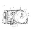
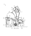
- FIG. 1 is an overall perspective view of the appearance of a printer according to an embodiment of the present invention.
- FIG. 2 is a perspective view showing the inside of the printer of FIG.
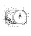
- FIG. 3 is a side view of the printer of FIG.
- FIG. 4A is an enlarged perspective view of the printing unit viewed from the front when the print head unit of FIG. 3 is in the closed position.
- 4B is an enlarged perspective view of the printing unit viewed from the front when the print head unit of FIG. 3 is in the open position.
- FIG. 5 is an enlarged perspective view of the printing unit of FIG. 4A as viewed from the back side.
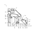
- FIG. 6 is an enlarged side view of the printing unit of FIG.
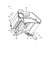
- FIG. 7 is a perspective view of the print head portion of FIG. 6 extracted from below.
- FIG. 1 is an overall perspective view of the appearance of a printer according to an embodiment of the present invention.
- FIG. 2 is a perspective view showing the inside of the printer of FIG.
- FIG. 3 is a side view of
- FIG. 8 is an enlarged side view of the print unit when the print head unit is in the closed position.
- FIG. 9 is an enlarged side view of the print unit when the print head unit is in the open position.
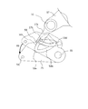
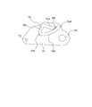
- FIG. 10 is a side view showing the head support portion and the damper support member extracted from the open / close position of the print head portion.
- FIG. 11 is a side view of the head support portion and the damper support member while the print head portion of FIG. 10 is moving to the open position.
- FIG. 12 is a side view of the head support portion and the damper support member after the print head portion of FIG. 10 has moved to the open position.
- FIG. 13 is a side view of the head support portion and the damper support member when the print head portion of FIG. 10 is moved from the open position to the close position.
- FIG. 10 is a side view showing the head support portion and the damper support member extracted from the open / close position of the print head portion.
- FIG. 11 is a side view of the head support portion and the damper
- FIG. 14 is a side view of the head support portion and the damper support member when the print head portion of FIG. 10 is moved from the open position to the close position.
- FIG. 15 is a side view for explaining another embodiment of the head support portion.
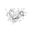
- FIG. 16 is a perspective view of the damper portion and the damper support member viewed from the side surface side of the printing portion of FIG.
- FIG. 17 is an exploded perspective view of the damper support member viewed from the side where the damper portion is mounted.
- 18A is a perspective view showing a connection portion between the outer damper portion and the damper support member of FIG. 18B is an exploded perspective view showing a connection position relationship between the outer damper portion and the damper support member of FIG. 18A.
- FIG. 19A is a perspective view of the damper portion and the damper support member as viewed obliquely from above.
- FIG. 19B is a perspective view of the damper portion viewed obliquely from below.
- FIG. 20 is a perspective view of the damper portion and the damper support member as viewed from above.
- FIG. 21 is an exploded perspective view of the outer damper portion.
- FIG. 22 is an exploded perspective view of the outer damper portion and the inner damper portion.
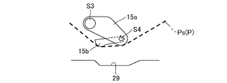
- FIG. 23A is an enlarged side view of the damper portion when a continuous sheet of front wound labels is set.
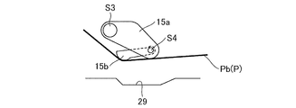
- FIG. 23B is an enlarged side view of the damper portion when the continuous paper of the back-wrap label is set.
- FIG. 24A is a side view of the damper portion at the previous stage of setting continuous paper to the paper feeding route.
- FIG. 24B is a side view of the damper unit in the case of the front winding label in a state where the roll-shaped continuous paper in the paper supply unit is reduced and the outer peripheral part of the roll-shaped continuous paper approaches the support shaft.
- FIG. 24C is a side view of the damper unit at the stage where the roll-like continuous paper in the paper supply unit starts to decrease in the case of the back-wrap label.
- FIG. 25A is a side view of the damper unit in the case of the front winding label, in which the roll-shaped continuous paper of the paper supply unit is in the initial stage.
- FIG. 25B is a side view of the damper unit in the case of the back-wrapped label, in which the roll-shaped continuous paper in the paper supply unit is reduced and the outer peripheral part of the roll-shaped continuous paper approaches the support shaft.
- FIG. 26 is a perspective view of the outer damper portion viewed from the front side of the printer.
- FIG. 27 is a perspective view showing the outer damper portion extracted from FIG.
- FIG. 28 is a perspective view showing the width adjustment guide part and the guide operation part 28 extracted from FIG.
- FIG. 29 is a perspective view showing a connection portion between the width adjustment guide portion and the guide operation portion.
- FIG. 30 is a perspective view of an engagement portion between the shaft portion of the guide operation portion and the width adjustment guide portion.
- the direction in which continuous paper (printing medium) is transported for printing specifically, the direction in which continuous paper is fed from the paper supply unit to the thermal head unit is referred to as the printing direction.
- Means the upstream side in the printing direction, and the downstream in the transport direction means the downstream side in the printing direction.
- FIG. 1 is an overall perspective view of the appearance of the printer 1 according to the present embodiment.
- the printer 1 has a label printing function for printing information such as characters, symbols, figures, or barcodes on a label temporarily attached to a mount.
- the front cover portion 2 in front of the printer 1 is provided with an operation panel portion 3, a power switch 4, and an issue port (medium discharge port) 5.
- the operation panel unit 3 includes an LCD (Liquid Crystal Display) for displaying messages and the like, and a plurality of keys (line key, feed key, function key, direction instruction key, cancel key, etc.) for operating the printer 1; A plurality of LEDs (Light Emitting Diode) indicating the state of the printer 1 are arranged.
- LCD Liquid Crystal Display
- keys line key, feed key, function key, direction instruction key, cancel key, etc.
- LEDs Light Emitting Diode
- an open cover portion 6 is mounted in a state that can be opened and closed vertically by two hinge portions 7.
- FIGS. 2 is a perspective view showing the inside of the printer 1 of FIG. 1
- FIG. 3 is a side view of the printer 1 of FIG.
- the front side (front cover portion 2 side) of the printer 1 is the front (downstream side in the continuous paper transport direction), and the back side (back cover portion side) opposite the rear side (upstream in the continuous paper transport direction). Side).
- a paper supply unit (medium supply unit) 10 disposed behind the printer 1 a print unit 11 disposed in front, and an ink ribbon unit 12 disposed above the printer are installed.
- the paper supply unit 10 is a component that supplies continuous paper (printing medium) P to the printing unit 11, and includes a support shaft 10a and a roll guide unit 10b installed at one end thereof.
- the support shaft 10a is a component that supports the continuous paper P wound up in a roll shape in a rotatable state.
- the roll guide portion 10b is a component that restricts the movement of the roll-shaped continuous paper P, and is movable in the axial direction of the support shaft 10a so that the position can be changed according to the width of the continuous paper P. is set up.
- the continuous paper P has, for example, a long mount and a plurality of labels temporarily attached at predetermined intervals along the longitudinal direction.
- a surface of the mount that contacts the adhesive surface of the label is coated with a release agent such as silicone, so that the label can be easily peeled off.
- a position detection mark indicating the position of the label is formed on the surface of the mount on which the label is not attached at predetermined intervals along the longitudinal direction.
- the label may be either thermal paper or plain paper. In the case of thermal paper, a thermal coloring layer that forms a specific color (black, red, etc.) when a predetermined temperature range is reached is formed on the surface.
- the front wound label is wound in a state where the label of the continuous paper P is positioned on the outer peripheral surface of the roll-shaped continuous paper P, and as shown in FIG. 3, the continuous paper Ps (P: broken line) is the paper supply unit. 10 is extended toward the bottom of the printing unit 11 from the center in the height direction.
- the back-wrapped label is wound in a state where the label of the continuous paper P is located on the inner peripheral surface side of the roll-shaped continuous paper P, and as shown in FIG. 3, the continuous paper Pb (P : Solid line) is fed out from the inner bottom surface of the printer 1 toward the bottom of the printing unit 11.
- the sheet passing route of the continuous paper P (Ps, Pb) in the printing unit 11 is the same for the front winding and the reverse winding. Further, the continuous paper P is transported with the surface (printed surface) on which the label is temporarily attached facing upward, whether it is a front wound label or a back wound label.
- the printing unit 11 is a component that performs printing on a label or the like of the continuous paper P.
- the print head unit 13 is installed inside the printer 1 so as to be opened and closed by swinging, as will be described later. Continuous paper from the medium conveyance path between the print head unit 13 and the support base 14 toward the issue port 5 (see FIG. 1) when the print head unit 13 is in the closed position (position where it abuts the platen roller unit 23). P is conveyed.
- the support base 14 is provided with a head lock lever portion 16 for maintaining the closed state (state in the closed position) of the print head portion 13.
- a head lock lever portion 16 for maintaining the closed state (state in the closed position) of the print head portion 13.
- the damper portion 15 is a component for relieving the stress acting on the continuous paper P.
- the damper portion 15 includes an outer damper portion 15a and an inner damper portion 15b.
- the outer damper portion 15a and the inner damper portion 15b are installed in a swingable state so that the stress acting on the continuous paper P can be alleviated.
- the ink ribbon unit 12 is a component that supplies and winds up an ink ribbon coated with printing ink, and includes a ribbon supply unit 12a and a ribbon winding unit 12b disposed on the front side thereof.
- the ribbon supply unit 12a is a component that supports the ink ribbon wound up in a roll shape in a rotatable state.
- the ribbon winding unit 12b is a component that winds and collects the printed ink ribbon RB. When an ink ribbon is used, the ink ribbon drawn out from the ribbon supply unit 12a is passed under the print head unit 13 and wound up by the ribbon winding unit 12b.
- the continuous paper P (Ps, Pb) fed out in a sheet form from the paper supply unit 10 passes through the damper unit 15 to the paper passing route between the print head unit 13 and the support base 14.
- a printing process is performed on a label or the like of the continuous paper P, and then the paper is discharged from the issuing port 5 to the outside of the printer 1.
- 4A is an enlarged perspective view of the printing unit viewed from the front when the printing head unit of FIG. 3 is in the closed position.
- 4B is an enlarged perspective view of the printing unit viewed from the front when the print head unit of FIG. 3 is in the open position.
- FIG. 5 is an enlarged perspective view of the printing unit of FIG. 4A as viewed from the back side of the printer 1.
- FIG. 6 is an enlarged side view of the printing unit of FIG.
- FIG. 7 is a perspective view of the print head portion of FIG. 6 extracted from below.
- the print head unit 13 is a head on one side surface of the print head unit 13 such that the front portion of the print head unit 13 can swing up and down (that is, open and close) about the rear swing shaft S1 (see FIGS. 5 and 7). It is supported by a support portion 17 (corresponding to a first support).
- the thermal head unit 18 On the lower surface of the print head unit 13 (the surface facing the sheet passing route), the thermal head unit 18 (see FIGS. 4B and 7) faces the continuous sheet disposed along the sheet route through the print surface. is set up.
- the thermal head unit 18 is a printing unit that performs printing on a label or the like of the continuous paper P by a heating resistor of a printing line 18L disposed on the printing surface.
- a plurality of heating resistors (heating elements) that generate heat when energized are arranged along the width direction of the continuous paper P (direction perpendicular to the conveyance direction of the continuous paper P).
- concave claw portions 19 and 19 are provided so as to sandwich the thermal head portion 18 therebetween. Further, on the lower surface of the print head portion 13, pins 20, 20 protruding outward from both side surfaces of the print head portion 13 are provided behind the concave claw portion 19.
- Such a print head unit 13 is urged in the opening direction by a torsion spring 21 mounted on the swing shaft S1 (see FIGS. 5 and 7).
- the closed state is maintained by the locking claw portions 22 of the support base 14 being caught.
- the lock claw portion 22 moves in the right direction in FIG.
- the print head portion 13 is automatically opened by the urging force of the torsion spring 21 as shown in FIG. 4B.
- the print head unit 13 When the print head unit 13 is in the closed position, the print surface of the thermal head unit 18 is pressed against the lower platen roller unit 23 (see FIGS. 4A and 4B), and the concave claw unit 19 of the print head unit 13 19 (see FIG. 4B and FIG. 7) is fitted to both ends of the rotation shaft S2 (see FIGS. 4A, 4B, and 6) of the platen roller portion 23.
- the platen roller unit 23 is a conveying unit that conveys the continuous paper P fed from the paper supply unit 10 to the issuing port 5 (see FIG. 1) along the paper route, and the surface thereof is elastic such as hard rubber. Covered with material.
- the platen roller portion 23 is installed on the upper portion of the support base 14 so as to be rotatable in the forward and reverse directions.
- a gear G1 is connected to one end of the rotation axis S2 of the platen roller portion 23 in the axial direction.
- the gear G1 is engaged with a rotating shaft of a driving body (not shown) such as a stepping motor via a timing belt (not shown), for example. Further, the gear G1 is connected to the gear G4 via the connecting gears G2 and G3 (see FIG. 5).
- a restraining portion 17a (see FIGS. 5 to 7) is integrally formed at the end portion on the damper portion 15 side in the head support portion 17 that supports the print head portion 13.
- the restraining portion 17a is formed at an end portion on the upstream side in the transport direction that is a position opposite to the front portion of the head support portion 17 with the swing axis S1 as a boundary.
- a pin 17b protruding from the surface of the restraining portion 17a facing the damper portion 15 is provided on the front side.
- the suppression unit 17 a and the pin 17 b are part of a mechanism that transmits the opening / closing operation of the print head unit 13 to the damper unit 15. The opening / closing mechanism will be described in detail later.
- a sheet position detection sensor (not shown) is provided between the thermal head unit 18 and the damper unit 15 in the sheet passing route of the printing unit 11.
- This paper position detection sensor is a sensor that detects the position of a label on the continuous paper P by detecting a position detection mark formed on the continuous paper P or a mount portion between adjacent labels. It is composed of a light transmission type sensor.
- the continuous paper P is conveyed by rotating the platen roller unit 23 with the continuous paper sandwiched between the thermal head unit 18 and the platen roller unit 23. Then, the print timing is set based on the information detected by the paper position detection sensor, and the heating resistor of the print line 18L is selectively heated by the print signal transmitted to the thermal head unit 18. As a result, desired information such as characters, symbols, figures or barcodes is printed on the label of the continuous paper P.
- the outer damper portion 15a of the damper portion 15 extends obliquely downward from the front side toward the rear side when the side surface of the printing portion 11 is viewed, and the front swing shaft S3 (FIGS. 4 and 6).
- the front portion is supported by a damper support member 25 (corresponding to a second support body) in a state in which the front portion can swing in the vertical direction.
- the coil spring 26 in FIG. 5 is a member that prevents the outer damper portion 15a from going too far upward (backward) and supports the outer damper portion 15a in a swingable state. is there.
- the inner damper unit 15b of the damper unit 15 extends obliquely downward from the rear side to the front side, as opposed to the outer damper unit 15a.
- the front part is supported by the rear part of the outer damper part 15a in a state in which the front part is swingable in the vertical direction around the moving shaft S4 (see FIGS. 4 and 6).
- the paper contact portion of the inner damper portion 15b is located downstream of the paper contact portion of the outer damper portion 15a in the transport direction of the continuous paper P. That is, the paper contact portion of the inner damper portion 15b is disposed between the print head portion 13 and the paper contact portion of the outer damper portion 15a.
- the height of the paper contact portion of the inner damper portion 15b is arranged at a position lower than the height of the paper contact portion of the outer damper portion 15a. That is, the height of the paper contact portion of the inner damper portion 15 b is disposed between the paper contact portion of the outer damper portion 15 a and the inner bottom surface of the printer 1.
- the configurations of the outer damper portion 15a and the inner damper portion 15b will be described in detail later.
- a width adjustment guide portion 27 is installed below the outer damper portion 15a so as to be movable along the axial direction of the swing shafts S3 and S4.
- the width adjustment guide unit 27 is a component that abuts both ends in the width direction of the continuous paper P conveyed from the paper supply unit 10 and guides the conveyance of the continuous paper P.
- the width adjustment guide portion 27 is connected to a guide operation portion 28 provided on the back side of the printer 1 in the outer damper portion 15a.
- the guide operation unit 28 is a knob for moving the width adjustment guide unit 27 according to the width of the continuous paper P and fixing the position of the width adjustment guide unit 27.
- a recessed portion 29 (see FIG. 6) is partially formed on the inner bottom surface of the printer 1 below the damper portion 15.
- the recessed portion 29 is provided in a region facing the width adjustment guide portion 27 of the damper portion 15 on the inner bottom surface of the printer 1 when the damper portion 15 is in the closed position.
- the bottom surface of the recessed portion 29 is recessed below the region other than the recessed portion 29 on the inner bottom surface of the printer 1.
- the lower end portion of the width adjusting guide portion 27 is at a position facing the recess portion 29 as shown in FIG.
- the lower end portion of the width adjusting guide portion 27 is not in contact with the surface of the recessed portion 29 on the inner bottom surface, and is separated from the surface of the recessed portion 29 by a predetermined distance.
- the lower end portion of the width adjustment guide portion 27 may be formed in an arc shape, for example. Details of the recess 29 will be described later.
- FIG. 8 is an enlarged side view of the print unit when the print head unit is in the closed position
- FIG. 9 is an enlarged side view of the print unit when the print head unit is in the open position. 8 and 9, the back surface of the damper support member 25 is shown through.
- the damper portion 15 moves upward (that is, the opening operation) in conjunction with the opening operation of the print head portion 13. That is, when the height of the reference position of the damper portion 15 when the print head portion 13 is in the closed position is the first height, when the print head portion 13 is opened, the height of the reference position of the damper portion 15 is interlocked with the height. Moves to a second height that is higher than the first height. When the print head unit 13 is closed, the height of the reference position of the damper unit 15 returns to the first height after the print head unit 13 is closed.
- the user opens the print head unit 13 and passes the continuous paper P drawn from the paper supply unit 10 near the inner bottom surface of the printer 1 when passing the continuous paper P through the paper route.
- the continuous paper P drawn from the paper supply unit 10 near the inner bottom surface of the printer 1 when passing the continuous paper P through the paper route.
- the damper portion 15 is installed on the inner bottom surface side of the printer 1, and the gap between the damper portion 15 and the inner bottom surface of the printer 1 is narrow. For this reason, if the damper unit 15 remains fixed and does not move to the open state, it is difficult for the user to pass the continuous paper P through the paper passing route. In addition, since the width adjustment guide portion 27 is attached to the lower portion of the damper portion 15, the continuous paper P may be caught on the width adjustment guide portion 27 when the continuous paper P is set.
- the damper unit 15 is lifted in conjunction with it, so that the opening for setting the continuous paper P is widened, and the visibility of the lower part of the damper unit 15 is improved. Can be improved. For this reason, the continuous paper P drawn from the paper supply unit 10 can be easily passed under the damper unit 15 without being caught by the width adjustment guide unit 27. Therefore, the operation of setting the continuous paper P to the paper passing route of the printer 1 can be facilitated.
- FIG. 10 is a side view showing the head support portion and the damper support member extracted when the print head portion is opened and closed.
- FIG. 11 is a side view of the head support portion and the damper support member while the print head portion of FIG. 10 is moving to the open position.
- FIG. 12 is a side view of the head support portion and the damper support member after the print head portion of FIG. 10 has moved to the open position.
- FIG. 13 is a side view of the head support portion and the damper support member when the print head portion of FIG. 10 is moved from the open position to the close position.
- FIG. 14 is a side view of the head support portion and the damper support member when the print head portion of FIG. 10 is moved from the open position to the close position.
- a two-dot chain line indicates the head support portion 17 (first support) and the damper support member 25 (second support) when in the closed position.
- 10 to 14 show side surfaces of the printing unit 11 shown in FIG.
- the printer 1 is a printer that prints on a continuous belt P having a long belt shape, and includes a platen roller unit 23 (not shown in FIGS. 10 to 14) that conveys the continuous paper P, a platen.
- a print head unit 13 that is movably provided at a closing position facing the roller unit 23 and an open position separated from the platen roller unit 23, and upstream of the print head unit 13 in the transport direction of the continuous sheet P.
- a damper portion 15 that is provided on the side, is movably provided at a closing position that contacts the continuous paper P and an open position that is spaced apart from the continuous paper, and relieves stress applied to the continuous paper P.
- the print head unit 13 is in a closed position where the print head unit 13 is opposed to the platen roller unit 23 and the damper unit 15 is in the closed position where the print unit 13 is in contact with the continuous paper P.
- the print head unit 13 moves to the open position when the damper unit 15 is in the open position separated from the platen roller unit 23 and the damper unit 15 is in the open position separated from the continuous paper P, the print head unit 13 is moved to the open position. In conjunction with this, the damper portion 15 moves to the open position.
- the print head unit 13 is in the open position where the print head unit 13 is separated from the platen roller unit 23 and the damper unit 15 is in the open position separated from the continuous paper P.
- the damper unit 15 is moved after the print head unit 13 is moved to the closed position. Move to the closed position.
- a swing shaft (corresponding to a print head portion support shaft) S1 that is swingably supported in the printer 1 is formed in the head support portion 17 that supports the print head portion 13. Further, the head support portion 17 is located on the upstream side in the transport direction with respect to the swing shaft S ⁇ b> 1, and has a restraining portion 17 a (corresponding to an engagement end portion) having an engagement portion that engages with a specific portion of the damper portion 15. ) Are integrally formed.
- the pin 17b which protrudes toward the damper part 15 is provided in the surface which faces the damper part 15 of the suppression part 17a.
- the pin 17b corresponds to an engagement portion that engages the damper portion 15 with a specific location (see FIG. 7).
- the suppression unit 17 a and the pin 17 b constitute a mechanism that opens and closes the damper unit 15 in conjunction with the opening and closing operation of the print head unit 13. This opening / closing operation will be described later.
- the print head unit 13 has a front portion that can swing up and down about the rear swing shaft S1 (see FIGS. 5 and 7) (that is, a state that can be opened and closed). ) Is supported by the head support portion 17 on one side surface of the print head portion 13.
- the damper support member 25 has a swing shaft (corresponding to a damper support shaft) S5 that is swingably supported inside the printer 1. Further, the damper support member 25 is formed with a groove portion 50 that engages with a pin 17b formed on the suppression portion 17a.
- the groove portion 50 includes a first groove 50a, a second groove 50b, and a third groove 50c, which are connected to each other to form a substantially triangular shape with each groove as one side.
- the first groove 50a is formed on the print head portion 13 side (upper side) of the damper support member 25, and is centered on the swing shaft S1 in a state where the damper portion 15 is located at the closed position where it contacts the continuous paper P.
- the head support portion 17 is formed along the movement locus of the pin 17b that moves when the head support portion 17 swings.
- the end of the first groove 50a is formed so as to be located on the upstream side in the transport direction from the center of the swing shaft S5 of the damper support member 25 in a state where the head support portion 17 is located at the closed position.
- the second groove 50b moves the pin 17b that moves when the head support portion 17 swings about the swing shaft S1 in a state where the damper portion 15 is located at an open position away from the inner bottom surface of the printer 1. It is formed along the trajectory, and is formed in a state in which the first groove 50a is connected through a path different from the first groove 50a from the downstream end side in the transport direction. Further, a convex portion 50e is formed at a terminal end portion (a connecting portion with a third groove 50c described later) which is an end portion opposite to an end portion connected to the first groove 50a of the second groove 50b.
- the third groove 50c is formed in a partial arc shape having a radius from the swing axis S5 to the pin 17b in a state where the head support portion 17 is located at the closed position, and the first groove 50a.
- the end side on the upstream side in the transport direction is connected to the end side on the upstream side in the transport direction of the second groove 50b.
- a ball plunger 51 is provided at an end portion where the swing shaft S ⁇ b> 5 is provided on the upstream side in the transport direction as a locking member that locks the damper portion 15 in a state where the damper portion 15 is located at the open position. ing.
- a ball button for locking the ball plunger 51 is provided at a predetermined location in the printer 1. When the ball plunger 51 and the ball button are locked, the damper support member 25 is locked at the open position.
- the damper portion 15 includes a torsion spring 30 on the swing shaft S5 as a biasing member that biases the damper portion 15 in the direction toward the closing position with the swing shaft S5 as a swing shaft.
- the damper support member 25 has a direction in which the rear portion of the damper support member 25 moves downward from the open position to the closed position with the swing shaft S5 as the swing center by the torsion spring 30, that is, the entire damper section 15 is the printer. 1 is biased in a direction approaching the inner bottom surface.
- the damper support member 25 is supported in the printer 1 in a state in which the rear portion is swingable in the vertical direction around the swing shaft S5. Since the pin 17b of the head support portion 17 is located in the third groove 50c when the damper support member 25 is swung in the state where the head support portion 17 is located at the closed position, the third groove 50c is located in the third groove 50c.
- the swinging of the support member 25 is not hindered.
- the rear portion of the damper support member 25 corresponds to the left side of FIGS.
- the head support portion 17 and the damper support member 25 move to the open position as follows.
- the head support portion 17 moves from the closed position to the open position, the head support portion 17 swings in the direction of the arrow R1 with the swing shaft S1 as the swing center. This is a case where the head support portion 17 moves from the position of the two-dot chain line shown in FIG. 11 to the position of the solid line. At this time, the pin 17b moves in the direction of the arrow R2 shown in FIG. 11 along the first groove 50a to the end 50d of the first groove 50a.
- damper support member 25 Since the damper support member 25 is biased toward the closed position by the torsion spring 30, when the head support portion 17 moves from the closed position to the open position, the damper support member is maintained at the closed position.
- the head support portion 17 and the damper support member 25 move to the open position in conjunction with each other, and the head support portion 17 and the damper support member 25 are locked at the open position.
- the head support portion 17 moves from the open position to the close position, the head support portion 17 swings in the direction of the arrow R5 with the swing shaft S1 as the swing center. This is a case where the head support portion 17 moves from the position of the two-dot chain line shown in FIG. 13 to the position of the solid line. At this time, the pin 17b moves along the second groove 50b in the direction of the arrow R6 shown in FIG.
- the damper unit 15 is moved to the closed position. For this reason, the continuous paper P is pressed toward the bottom surface of the printer 1 by the print head unit 13 before the damper unit 15. That is, the print start position on the continuous paper P is pressed at a position that matches the corresponding position of the print head unit 13. For this reason, when the damper part 15 moves to the closing position, the continuous paper P is not pulled by the damper part 15 and the print start position is not displaced.
- the opening / closing mechanism of the print head unit 13 and the damper unit 15 is not limited to the above configuration.
- a ball button may be provided on the damper support member 25 and a ball plunger may be provided inside the printer 1.
- FIG. 15 is a side view for explaining another embodiment of the head support portion.
- a step 50f may be formed between the first groove 50a and the second groove 50b.
- the pin 17b cannot move in the direction of entering the first groove 50a from the second groove 50b due to the step 50f.
- the pin 17b enters the first groove 50a, so that the damper unit 15 is closed together with the print head unit 13 closing operation. Operation can be prevented.
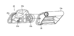
- FIG. 16 is a perspective view of the damper portion and the damper support member viewed from the side surface side of the printing portion of FIG.
- FIG. 17 is an exploded perspective view of the damper support member viewed from the side where the damper portion is mounted.
- 18A is a perspective view showing a connection portion between the outer damper portion and the damper support member of FIG. 18B is an exploded perspective view showing a connection position relationship between the outer damper portion and the damper support member of FIG. 18A.
- surfaces of the damper support member 25 the side surface which the outer damper part 15a opposes is called an inner surface
- the side surface of the back side is called an outer surface.
- Bearing end portions 25 b that penetrate both side surfaces of the damper support member 25 are formed on one end side in the longitudinal direction of the damper support member 25.
- the bearing hole 25b is inserted in a state where the swing shaft S5 is fixed so as not to swing, and is stopped by a screw 35a (see FIG. 17) so as not to come off.
- the torsion spring 30 is mounted in a state where the ring is fitted into the swing shaft S5.
- a hole 25c penetrating between both side surfaces of the damper support member 25 is formed on the other end side in the longitudinal direction of the damper support member 25.
- the protrusion 36 formed on the side surface of the outer damper portion 15a is disposed at a position where it protrudes from the hole portion 25c.
- the hole 25c is formed so as to allow a predetermined dimension margin around the protrusion 36.
- the outer surface of the damper support member 25 is formed so as to be recessed in the thickness direction.
- a protrusion 25d is formed in the vicinity of the hole 25c.
- a coil spring 26 is installed between the projection 25d of the damper support member 25 and the projection 36 of the outer damper portion 15a so as to be bridged. The coil spring 26 is biased so as to pull the protrusion 36 of the outer damper portion 15a in the direction of the protrusion 25d of the damper support member 25.
- the outer damper portion 15a is firmly supported along the axial direction of the swing shaft S3 and is restrained from going too far upward, and swings so as to relieve the stress applied to the continuous paper P. It is supported in a free state.
- a bearing hole 25e (see FIG. 17) is formed in the vicinity of the center in the longitudinal direction in the upper part of the inner side surface of the damper support member 25.
- the swing shaft S3 of the outer damper portion 15a is inserted so as not to swing, and is fixed by a screw 35b (see FIG. 16) so as not to come off.
- FIG. 19A is a perspective view of the damper portion and the damper support member as viewed obliquely from above.
- FIG. 19B is a perspective view of the damper portion viewed obliquely from below.
- FIG. 20 is a perspective view of the damper portion and the damper support member as viewed from above.
- FIG. 21 is an exploded perspective view of the outer damper portion.
- FIG. 22 is an exploded perspective view of the outer damper portion and the inner damper portion.
- a bearing hole portion 37 is formed on one end side (upper end side) in the longitudinal direction when the outer damper portion 15a is viewed from the side.
- a rocking shaft S3 is inserted into the bearing hole 37.
- the outer damper portion 15a is pivotally supported in a swingable state about the swing shaft S3. That is, the outer damper portion 15a is pivotally supported in a vertically swingable state so that the other end portion (lower end portion) in the longitudinal direction can relieve the stress applied to the continuous paper P around the swing shaft S3. ing.
- a slide hole portion 38 is formed along the axial direction of the swing axis S3 on the surface of the outer damper portion 15a on the back side of the printer 1.
- the shaft portions of the two guide operation portions 28 are inserted into the slide hole portion 38.
- a width adjustment guide portion 27 is connected to the shaft portion of the guide operation portion 28 by a pin 39 (see FIGS. 19A and 19B).
- the back guide operation unit 28 is fixed.
- the guide operation unit 28 on the front side can be moved along the slide hole 38 and can be fixed in accordance with the width of the continuous paper P.
- the width adjustment guide part 27 and the guide operation part 28 will be described in detail later.
- the sheet contact portion with which the continuous sheet P comes into contact with the end side on the upstream side in the transport direction when the outer damper portion 15a is viewed from the side surface is formed in an arc shape when the outer damper portion 15a is viewed from the side surface side.
- a bearing hole 40 is formed on the end of the outer damper portion 15a on the upstream side in the transport direction.
- the swing shaft S4 is inserted in the bearing hole 40 in a fixed state so as not to swing.
- the swing shaft S4 is disposed in parallel to the swing shaft S3.
- An inner damper portion 15b is pivotally supported on the swing shaft S4.
- the inner damper portion 15b has two support portions 41a and 41a and a main body portion 41b integrally formed so as to bridge them to one end side thereof.
- a bearing hole 41c is formed at one end of each of the support portions 41a and 41a.
- a swing shaft S4 is inserted into the bearing holes 41c and 41c. As a result, the inner damper portion 15b is pivotally supported in a swingable state about the swing shaft S4.
- a torsion spring 42 (see FIGS. 20 and 22) is attached to one end side of the swing shaft S4 in a state of being engaged with the inner damper portion 15b. Due to the urging force of the torsion spring 42, the inner damper portion 15b has its lower end portion (paper contact portion) swingable in the vertical direction so that the stress acting on the continuous paper P can be relieved. Is pivotally supported.
- the sheet contact portion side that contacts the continuous sheet P in the main body portion 41b of the inner damper portion 15b is formed in an arc shape when the inner damper portion 15b is viewed from the side.
- a recessed portion 41d is formed on the main body portion 41b on the side opposite to the paper contact portion.
- a plurality of reinforcing plates 41e are arranged at predetermined intervals along the axial direction of the swing shaft S4 in the hollow portion 41d.
- the inner damper portion 15b is pivotally supported on the outer damper portion 15a, so that the stress acting on the continuous paper P is increased even in the case of the back-wrapped label without increasing the size of the printer 1.
- a damper function that can be sufficiently relaxed can be added.
- the outer damper portion 15a and the inner damper portion 15b as described above are made of, for example, a transparent resin.
- the visibility of the continuous paper P in the damper unit 15 can be improved, so that the operation of setting the continuous paper P on the paper passing route of the printer 1 can be further facilitated. That is, it is possible to easily adjust the position by checking the position of the opaque width adjusting guide portion 27 through the transparent damper portion.
- the transparent means that the other side of the member is visible, and the transparent material means not only a non-colored material but also a colored translucent material or a non-colored material. Including transparent materials.
- a gap 43 (see FIGS. 19B and 20) is formed between the main body portion 41b of the inner damper portion 15b and the outer damper portion 15a so as not to block the movement of the width adjusting guide portion 27.
- FIG. 23A is an enlarged side view of the damper portion when the continuous paper of the front winding label is set.
- FIG. 23B is an enlarged side view of the damper portion when continuous paper of the back-wrap label is set.
- the continuous paper Ps is drawn out from the center in the height direction of the paper supply unit 10 and is passed under the damper unit 15. Therefore, the outer damper unit 15a and the inner damper unit are provided. 15b is set to the paper passing route in a state where both are in contact. For this reason, since the stress acting on the continuous paper Ps can be sufficiently relaxed, the continuous paper Ps can be transported satisfactorily and the print quality can be ensured.
- the continuous paper P is drawn out from around the inner bottom surface of the printer 1 and passed under the damper portion 15, so that only the outer damper portion 15 a is used. Is disposed (when there is no inner damper portion 15b), the stress acting on the continuous paper P set in the paper passing route may not be sufficiently relaxed. For this reason, the continuous paper P cannot be conveyed well, and the print quality may deteriorate.
- the paper passing route is different depending on the form of the label such as the back wound label or the front wound label or the diameter of the roll label, it is continuous. Since the paper Pb is set in the paper passing route in a state where it is in contact with at least the inner damper portion 15b, the stress acting on the continuous paper Pb can be sufficiently relaxed, so that the continuous paper Pb can be transported satisfactorily and print quality is ensured. be able to.
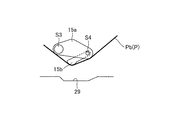
- FIG. 24A is a side view of the damper portion at the previous stage of setting continuous paper to the paper feeding route.
- FIG. 24B is a case of a front winding label, in which the roll-shaped continuous paper Ps of the paper supply unit 10 decreases and the outer peripheral portion of the roll-shaped continuous paper Ps approaches the support shaft 10a (the roll diameter is small). Illustrated.
- the pressing force of the continuous paper Ps against the outer damper portion 15a becomes weak and the height of the outer damper portion 15a does not change, but the inner damper portion 15b is lifted. Further, the impact caused by the force pulled in the direction opposite to the transport direction acting on the continuous paper Ps can be reduced.
- FIG. 24C illustrates the case of the back-wrapped label where the roll-shaped continuous paper Pb of the paper supply unit 10 is in the initial stage (the roll diameter is large).
- the feeding position of the continuous paper Pb is low (close to the bottom surface of the printer 1)
- the continuous paper Pb is in contact with the outer damper portion 15a
- the pressing force is weak and the height of the outer damper portion 15a is not changed.
- the damper 15b is lifted, and the impact caused by the force pulled in the direction opposite to the transport direction acting on the continuous paper Pb can be reduced.
- FIG. 25A exemplifies a case of a front winding label in which the roll-shaped continuous paper Ps of the paper supply unit 10 is in the initial stage (the roll diameter is large).
- the feeding position of the continuous paper Ps is high, both the outer damper portion 15a and the inner damper portion 15b are lifted, and the impact due to the force pulled in the direction opposite to the transport direction acting on the continuous paper Ps can be reduced. .
- FIG. 25B shows a case of a back-wrap label where the roll-shaped continuous paper Pb of the paper supply unit 10 is reduced and the outer peripheral portion of the roll-shaped continuous paper Pb approaches the support shaft 10a (the roll diameter is small). Illustrated. In this case, since the feeding position of the continuous paper Pb is higher than the initial stage, both the outer damper portion 15a and the inner damper portion 15b are lifted, and an impact due to a force pulled in the direction opposite to the transport direction acting on the continuous paper Pb is applied. Can be relaxed.
- FIG. 26 is a perspective view of the outer damper portion viewed from the front side of the printer 1.
- FIG. 27 is a perspective view showing the outer damper portion extracted from FIG.
- FIG. 28 is a perspective view showing the width adjustment guide part and the guide operation part 28 extracted from FIG.
- FIG. 29 is a perspective view showing a connection portion between the width adjustment guide portion and the guide operation portion.
- FIG. 30 is a perspective view of an engagement portion between the shaft portion of the guide operation portion and the width adjustment guide portion. In FIG. 30, the pin 39 is omitted in order to make the shaft portion 28a of the guide operation portion 28 easier to see.
- two guide rail portions 45 are formed inside the outer damper portion 15 a in a state of extending along the slide hole portion 38 so as to sandwich the upper and lower sides of the slide hole portion 38. ing.
- the guide rail portion 45 is formed integrally with the outer damper portion 15a, and is formed of, for example, a transparent resin.
- the pin 39 for connecting the width adjustment guide portion 27 and the guide operation portion 28 is disposed at a position sandwiched between the two guide rail portions 45 of the outer damper portion 15a.
- the pin 39 On the outer periphery of the pin 39, as shown in FIGS. 26, 28 and 29, two convex portions 39a, 39a are formed to project in the radial direction.
- the convex portions 39a and 39a are formed at opposite positions separated from each other by 180 degrees.
- the pin 39 is also swung. Then, the two projecting portions 39a, 39a of the pin 39 are pressed against the inner surfaces of the two guide rail portions 45 by the swinging position of the pin 39, so that the guide rail portion 45 bends and the pin 39 has two guides. It is fixed by abutting and being sandwiched between the rail portions 45. Thereby, the guide operation part 28 is locked. On the other hand, when the guide operation portion 28 is further swung 90 degrees from the locked state, the two convex portions 39a and 39a of the pin 39 are separated from the two guide rail portions 45, so that the locked state of the guide operation portion 28 is released. . Therefore, in the present embodiment, the position of the width adjustment guide portion 27 can be set with a simple structure and a simple operation.
- a convex portion 28 b is formed on the outer periphery of the shaft portion 28 a of the guide operation portion 28.
- a range setting hole 27b is formed on the outer periphery of the hole 27a into which the shaft portion 28a of the guide operation portion 28 is inserted in a state of communicating with the hole 27a.
- the convex portion 28b is disposed in the range setting hole 27b, and the guide operation portion 28 can be swung in the circumferential range ⁇ of the range setting hole 27b.
- the continuous paper P is transported from the paper supply unit 10 side to the printing unit 11 side, that is, from the upstream side to the downstream side in the transport direction (referred to as forward feed).
- the continuous paper P may be conveyed from the printing unit 11 side to the paper supply unit 10 side, that is, from the downstream side in the conveyance direction to the upstream side in order to align the print start position (referred to as backfeed). ).
- the continuous paper P stretched between the paper supply unit 10 and the printing unit 11 is disposed at a position away from the inner bottom surface of the printer 1. In this state, tension is always applied to the continuous paper P.
- the continuous paper P may be loosened, and the continuous paper P may contact the inner bottom surface of the printer 1 at a position corresponding to the width adjustment guide portion 27 on the inner bottom surface of the printer 1.
- the continuous paper P passes over the lower end of the width adjustment guide 27 from the gap between the width adjustment guide 27 and the inner bottom surface of the printer 1 and is regulated by the width adjustment guide 27. It may go out of the guide area. In this state, when the printing operation returns to the forward feed, the continuous paper P is conveyed in a state where the damper unit 15 does not function.
- a recess 29 is provided on the inner bottom surface of the printer 1.
- the bottom surface of the recess 29 is located below the internal bottom surface of the printer 1.
- the continuous paper P is disposed so as to bridge the upstream side and the downstream side of the recess 29 by its own rigidity. Due to this configuration, when the continuous paper P is back-fed from the printing unit 11 to the paper supply unit 10, the continuous paper P contacts the inner bottom surface of the printer 1, but contacts the bottom surface of the recess 29. There is no.
- the lower end of the width adjustment guide portion 27 is closer to the bottom surface of the concave portion 29 than the continuous paper P. is there. For this reason, the continuous paper P does not get over the lower end of the width adjustment guide portion 27 and go out of the guide area regulated by the width adjustment guide portion 27. For this reason, when the printing operation is returned to the forward feed, the continuous paper P does not run on the width adjustment guide portion 27, and the function of the damper portion 15 is not impaired. Therefore, it is possible to avoid a problem that the printing position is deviated from the planned position or the printing density is reduced, so that the printing quality of the printer 1 can be ensured.
- the cross-sectional shape of the depression 29 is formed such that the slope on the upstream side in the transport direction is gentler than the slope on the downstream side in the transport direction.
- the inner wall surface of the recess 29 may be substantially perpendicular to the inner bottom surface of the printer 1.
- a plurality of protrusions (not shown) extending along the conveyance direction of the continuous paper P are arranged at predetermined intervals along the width direction of the continuous paper P on the inner bottom surface of the printer 1 including the depression 29. Also good. As a result, the flow of the continuous paper P can be made smooth at the time of back feed, so that the problem of the continuous paper P being jammed below the damper portion 15 can be reduced or prevented.
- the continuous paper P fed out from the paper supply unit 10 is passed under the damper unit 15 and passed between the print head unit 13 and the support base 14. At this time, since the damper portion 15 is lifted and opened, the setting operation of the continuous paper P can be facilitated.
- the case where continuous paper in which a plurality of labels are temporarily attached to a mount is used as a print medium is not limited to this.
- an adhesive surface is provided on one side.
- a continuous label a label without a mount
- a continuous sheet continuous sheet
- the mountless label, continuous sheet or film can have position detection marks.
- a roller containing silicone can be provided while the conveyance path is non-adhesive coated.
Landscapes
- Electronic Switches (AREA)
- Handling Of Continuous Sheets Of Paper (AREA)
- Handling Of Sheets (AREA)
- Common Mechanisms (AREA)
- Printers Characterized By Their Purpose (AREA)
- Accessory Devices And Overall Control Thereof (AREA)
Abstract
プリンタは、連続紙を搬送するプラテンローラ部(23)と、連続紙に印字を行う印字ヘッド部(13)と、連続紙に働く応力を緩和するダンパ部(15)とを備え、印字ヘッド部(13)がプラテンローラ部(23)から離間した開放位置にありかつダンパ部(15)が連続紙から離間する開放位置にある状態から、印字ヘッド部(13)がプラテンローラ部(23)に対向する閉止位置にありかつダンパ部(15)が連続紙に当接する閉止位置にある状態に移行する場合には、印字ヘッド部(13)が閉止位置へ移動した後、ダンパ部(15)が閉止位置に移動する。
Description
本発明は、文字、記号、図形又はバーコード等の所望の情報をラベル等の印字媒体に印字するプリンタに関する。
製品の製造、管理、流通等の分野では、製品に関する情報が視認可能に印字されて製品に取り付けられるタグや、製品などの対象物(以下、被着体という)に、直接、貼付されるラベルが用いられる。
一例として、ラベルの場合、長尺帯状の台紙に複数のラベルが仮着された連続紙(以下、連続紙という)として用意されている。このため、この連続紙における個々のラベルに印字することのできるプリンタが用いられる。
連続紙に仮着されたラベルに印字を可能にするプリンタは、供給される連続紙に印字するためのサーマルヘッドを備えた印字部と、連続紙に加わる応力を緩和するダンパ部とを有し、印字部におけるサーマルヘッドに対応する位置に、連続紙の印字開始位置が合わせられるように構成されている。また、プリンタ内部では、ダンパ部は、連続紙がダンパ部に押し当てられる連続紙の搬送路上に設けられている。
通常、プリンタでは、連続紙の交換やメンテナンス等が行われ、その都度、連続紙を搬送路にセットする作業が必要である。このプリンタでは、ダンパ部が連続紙に押し当てられる構成を有するため、連続紙を搬送路にセットする作業が手間であった。
そこで、印字部とともにダンパ部を開放可能な構成にすることにより、ユーザが連続紙を搬送路にセットする作業を簡便化したプリンタが提案されている(JP2015-123626A参照)。
JP2015-123626Aに記載されたプリンタでは、ユーザが印字部を開放状態に操作すると、印字部の動作に連動してダンパ部が開放状態に遷移するように構成されている。また、ユーザが印字部を閉止状態に操作すると、印字部の動作に連動してダンパ部が閉止状態に遷移するように構成されている。
JP2015-123626Aに記載されたプリンタでは、連動構造の印字部とダンパ部とが開放された状態から閉止された状態に遷移させる過程において、印字部よりも搬送方向上流側にあるダンパ部が印字部で連続紙を挟持する寸前に連続紙の位置を動かしてしまい、印字部で連続紙を挟持できない場合があることが明らかになってきた。
連続紙における次の印字開始位置が印字ヘッド部に対応する位置からずれた場合には、連続紙のセット作業を再度行う必要があるため、作業を難しくしていた。
そこで、本発明は、連続紙を印字部及びダンパ部にセットする際の作業性を損なうこと無く、セット作業時における印字部及びダンパ部の開閉動作に伴う連続紙の位置ずれを防止することを目的とする。
本発明のある態様によれば、長尺帯状の連続紙に印字を行うプリンタであって、前記連続紙を搬送するプラテンローラ部と、前記プラテンローラ部に対向する閉止位置及び前記プラテンローラ部から離間した開放位置に移動自在に設けられ、前記連続紙に印字を行う印字ヘッド部と、前記印字ヘッド部の前記連続紙の搬送方向における上流側に設けられ、前記連続紙に当接する閉止位置及び前記連続紙から離間する開放位置に移動自在で、前記連続紙に加わる応力を緩和するダンパ部と、を備え、前記印字ヘッド部がプラテンローラ部に対向する閉止位置にありかつ前記ダンパ部が前記連続紙に当接する閉止位置にある状態から、前記印字ヘッド部がプラテンローラ部から離間した開放位置にありかつ前記ダンパ部が前記連続紙から離間する開放位置にある状態に移行する場合には、前記印字ヘッド部が開放位置へ移動すると、前記印字ヘッド部に連動して前記ダンパ部が開放位置へ移動し、前記印字ヘッド部がプラテンローラ部から離間した開放位置にありかつ前記ダンパ部が前記連続紙から離間する開放位置にある状態から、前記印字ヘッド部がプラテンローラ部に対向する閉止位置にありかつ前記ダンパ部が前記連続紙に当接する閉止位置にある状態に移行する場合には、前記印字ヘッド部が閉止位置へ移動した後、前記ダンパ部が閉止位置に移動する、プリンタが提供される。
上記の態様によれば、供給された連続紙を印字部及びダンパ部にセットする際の作業性を損なうこと無く、作業時における印字部及びダンパ部の開閉動作に伴う連続紙の位置ズレによる印字不良を防止することができる。
以下、本発明の一例としての実施の形態について、図面に基づいて詳細に説明する。なお、実施の形態を説明するための図面において、同一の構成要素には原則として同一の符号を付し、その繰り返しの説明は省略する。
また、連続紙(印字媒体)を印字のために搬送する方向、具体的には連続紙を用紙供給部からサーマルヘッド部に送る方向を印字方向といい、特に説明がない場合、搬送方向上流とは印字方向において上流側のことをいい、搬送方向下流とは印字方向において下流側のことをいう。
図1は本実施の形態に係るプリンタ1の外観の全体斜視図である。
本実施の形態のプリンタ1は、例えば、台紙に仮着されたラベルに、文字、記号、図形又はバーコード等のような情報を印字するラベル印字機能を備えている。
プリンタ1の正面のフロントカバー部2には、操作パネル部3と、電源スイッチ4と、発行口(媒体排出口)5とが設けられている。
操作パネル部3には、メッセージ等を表示するLCD(Liquid Crystal Display)と、プリンタ1の動作を操作する複数のキー(ラインキー、フィードキー、ファンクションキー、方向指示キー及びキャンセルキー等)と、プリンタ1の状態を示す複数のLED(Light Emitting Diode)とが配置されている。
プリンタ1の片側側面には、オープンカバー部6が2箇所のヒンジ部7により上下方向に開閉自在の状態で装着されている。
次に、プリンタ1の内部構造について図2及び図3を参照して説明する。図2は図1のプリンタ1の内部を示した斜視図、図3は図2のプリンタ1の側面図である。なお、以下の説明ではプリンタ1の正面側(フロントカバー部2側)を前方(連続紙の搬送方向下流側)、その向かい側の背面側(バックカバー部側)を後方(連続紙の搬送方向上流側)という。
プリンタ1の内部には、その後方に配置された用紙供給部(媒体供給部)10と、前方に配置された印字部11と、その上方に配置されたインクリボン部12とが設置されている。
用紙供給部10は、連続紙(印字媒体)Pを印字部11に供給する構成部であり、支持軸10aと、その一端に設置されたロールガイド部10bとを備えている。
支持軸10aは、ロール状に巻き取られた連続紙Pを回転自在の状態で支持する構成部である。ロールガイド部10bは、ロール状の連続紙Pの移動を規制する構成部であり、連続紙Pの幅に応じて位置を変えられるように支持軸10aの軸方向に沿って移動自在の状態で設置されている。
連続紙Pは、例えば、長尺状の台紙と、その長手方向に沿って予め決められた間隔毎に仮着された複数枚のラベルとを有している。台紙においてラベルの粘着面が接触する面には、シリコーン等のような剥離剤がコーティングされており、ラベルを容易に剥離することが可能になっている。また、台紙においてラベルが貼られていない面には、長手方向に沿って予め決められた間隔毎にラベルの位置を示す位置検出マークが形成されている。ラベルは、感熱紙を使用する場合と普通紙を使用する場合とがある。感熱紙の場合は、その表面に、予め決められた温度領域に達すると特定の色(黒や赤等)に発色する感熱発色層が形成されている。
また、連続紙Pには、表巻きラベルと裏巻きラベルとの2種類がある。表巻きラベルは、連続紙Pのラベルがロール状の連続紙Pの外周面に位置する状態で巻回されており、図3で示すように、連続紙Ps(P:破線)が用紙供給部10の高さ方向中央あたりから印字部11の底部に向けて繰り出されている。これに対して、裏巻きラベルは、連続紙Pのラベルがロール状の連続紙Pの内周面側に位置する状態で巻回されており、図3に示すように、連続紙Pb(P:実線)がプリンタ1の内部底面あたりから印字部11の底部に向けて繰り出されている。なお、表巻きでも裏巻きでも印字部11での連続紙P(Ps,Pb)の通紙ルートは同じである。また、表巻きラベルでも裏巻きラベルでも連続紙Pはラベルが仮着された面(被印字面)を上に向けた状態で搬送される。
印字部11は、連続紙Pのラベル等に印字を行う構成部であり、印字ヘッド部13と、その下方に配置された支持台14と、それらの後方(印字工程時の連続紙Pの搬送上流)に配置されたダンパ部15とを備えている。
印字ヘッド部13は、後述のように、揺動により開閉自在の状態でプリンタ1の内部に設置されている。印字ヘッド部13が閉止位置(プラテンローラ部23に当接する位置)にあるときの印字ヘッド部13と支持台14との間の媒体搬送路から発行口5(図1参照)に向けて連続紙Pが搬送される。
支持台14には、印字ヘッド部13の閉止状態(閉止位置に位置する状態)を維持するヘッドロックレバー部16が設置されている。このヘッドロックレバー部16を操作すると印字ヘッド部13の閉止状態が解除され、印字ヘッド部13の前方部が持ち上がり、印字ヘッド部13が開く(プラテンローラ部23に対して離間する)ようになっている。
ダンパ部15は、連続紙Pに働く応力を緩和するための構成部である。本実施の形態においては、ダンパ部15が、アウターダンパ部15aとインナーダンパ部15bとを備える。印字ヘッド部13が閉止位置にあるときにおいて、アウターダンパ部15a及びインナーダンパ部15bは、それぞれ連続紙Pに働く応力を緩和可能なように揺動自在の状態で設置されている。
インクリボン部12は、印字用インクを塗布したインクリボンを供給し、巻き取る構成部であり、リボン供給部12aと、その前方横に配置されたリボン巻き取り部12bとを備えている。リボン供給部12aは、ロール状に巻き取られたインクリボンを回転自在の状態で支持する構成部である。リボン巻き取り部12bは、印字済みのインクリボンRBを巻き取り回収する構成部である。なお、インクリボンを使用する場合は、リボン供給部12aから引き出されたインクリボンを印字ヘッド部13の下に通してリボン巻き取り部12bで巻き取る。
このようなプリンタ1においては、用紙供給部10からシート状に繰り出された連続紙P(Ps,Pb)がダンパ部15を介して印字ヘッド部13と支持台14との間の通紙ルートに搬送され、その途中において連続紙Pのラベル等に印字処理がなされた後、発行口5からプリンタ1の外部に排出されるようになっている。
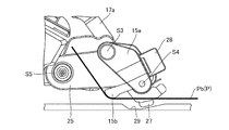
次に、上記した印字部11の構成について図4A,図4B~図7を参照して説明する。図4Aは図3の印字ヘッド部が閉止位置にあるときの印字部を正面から見た拡大斜視図である。図4Bは図3の印字ヘッド部が開放位置にあるときの印字部を正面から見た拡大斜視図である。図5は図4Aの印字部を、プリンタ1の背面側から見た拡大斜視図である。図6は図3の印字部の拡大側面図である。図7は図6の印字ヘッド部を抜き出して下側から見た斜視図である。
印字ヘッド部13は、その前方部が後方の揺動軸S1(図5及び図7参照)を中心に上下方向に揺動(すなわち、開閉)自在の状態で印字ヘッド部13の片側側面のヘッド支持部17(第1の支持体に相当する)に支持されている。
印字ヘッド部13の下面(通紙ルートを向く面)には、サーマルヘッド部18(図4B及び図7参照)がその印字面を通紙ルートに沿って配置された連続紙に対向した状態で設置されている。サーマルヘッド部18は、その印字面に配置された印字ライン18Lの発熱抵抗体により連続紙Pのラベル等に印字を行う印字手段である。この印字ライン18Lには、通電により発熱する複数の発熱抵抗体(発熱素子)が連続紙Pの幅方向(連続紙Pの搬送方向に対し直交する方向)に沿って並んで配置されている。
印字ヘッド部13の前方側の下面にはサーマルヘッド部18を挟むように凹状爪部19,19(図4B及び図7参照)が設けられている。また、印字ヘッド部13の下面において凹状爪部19の後方には、印字ヘッド部13の両側面から外方に突出するピン20,20が設けられている。
このような印字ヘッド部13は、揺動軸S1(図5及び図7参照)に装着されたトーションバネ21により開方向に付勢されているが、印字ヘッド部13の下部のピン20,20に、支持台14のロック爪部22,22が引っ掛かることにより閉止状態が維持されている。ロック爪部22は、上記ヘッドロックレバー部16を図6の右方向に引くと、それに連動して図6の右方向に移動し、ピン20から外れるようになっている。ロック爪部22がピン20から外れると、図4Bに示すように、印字ヘッド部13は、トーションバネ21の付勢力により自動的に開くようになっている。
また、印字ヘッド部13が閉止位置にあるときには、サーマルヘッド部18の印字面が下方のプラテンローラ部23(図4A,図4B参照)に押し付けられるとともに、印字ヘッド部13の凹状爪部19,19(図4B及び図7参照)がプラテンローラ部23の回動軸S2(図4A,図4B及び図6参照)の両端部に嵌められるようになっている。
プラテンローラ部23は、用紙供給部10から繰り出された連続紙Pを通紙ルートに沿って発行口5(図1参照)へ搬送する搬送手段であり、その表面は硬質ゴム等のような弾性材料により被覆されている。このプラテンローラ部23は、正逆方向に回動可能な状態で支持台14の上部に設置されている。プラテンローラ部23の回動軸S2の軸方向一端には、ギアG1が接続されている。このギアG1は、例えば、タイミングベルト(図示せず)等を介してステッピングモータのような駆動体(図示せず)の回動軸に係合されている。また、ギアG1は、連結ギアG2,G3を介してギアG4に接続されている(図5参照)。
また、本実施の形態においては、印字ヘッド部13を支持するヘッド支持部17においてダンパ部15側の端部に抑止部17a(図5~図7参照)が一体形成されている。この抑止部17aは、揺動軸S1を境にしてヘッド支持部17の前方部と対極の位置である搬送方向上流側の端部に形成されている。この抑止部17aの先端側においてダンパ部15を向く面には、その面から突出するピン17b(図7参照)が設けられている。抑止部17a及びピン17bは、印字ヘッド部13の開閉動作をダンパ部15に伝える機構の一部である。この開閉機構については、後ほど詳細に説明する。
なお、印字部11の通紙ルートにおいてサーマルヘッド部18とダンパ部15との間には、用紙位置検出センサ(図示せず)が設けられている。この用紙位置検出センサは、連続紙Pに形成された位置検出マークや隣り合うラベル間の台紙部分を検出することにより連続紙Pのラベルの位置を検出するセンサであり、例えば、光反射型又は光透過型のセンサにより構成されている。
印字工程時には、サーマルヘッド部18とプラテンローラ部23との間に連続紙を挟み込んだ状態でプラテンローラ部23を回動させることにより連続紙Pを搬送する。そして、用紙位置検出センサにより検出された情報に基づいて印字タイミングを図り、サーマルヘッド部18に送信された印字信号により印字ライン18Lの発熱抵抗体を選択的に発熱させる。これにより、連続紙Pのラベルに、文字、記号、図形又はバーコード等のような所望の情報を印字する。
一方、ダンパ部15のアウターダンパ部15aは、印字部11の側面を見た場合に前方側から後方側に向かって斜め下方に延びており、前方側の揺動軸S3(図4及び図6参照)を中心にして、前方部が上下方向に揺動自在の状態でダンパ支持部材25(第2の支持体に相当する)に支持されている。なお、図5のコイルバネ26は、後述するように、アウターダンパ部15aが上方側(後方側)に行きすぎないように抑制するとともに、アウターダンパ部15aを揺動自在の状態で支持する部材である。
また、ダンパ部15のインナーダンパ部15bは、印字部11の側面を見た場合に、アウターダンパ部15aとは逆に後方側から前方側に向かって斜め下方に延びており、後方側の揺動軸S4(図4及び図6参照)を中心にして、前方部が上下方向に揺動自在の状態でアウターダンパ部15aの後方部に支持されている。
印字工程時において、インナーダンパ部15bの用紙接触部は、アウターダンパ部15aの用紙接触部よりも連続紙Pの搬送方向下流側に位置している。すなわち、インナーダンパ部15bの用紙接触部は、印字ヘッド部13とアウターダンパ部15aの用紙接触部との間に配置されている。
また、インナーダンパ部15bの用紙接触部の高さは、アウターダンパ部15aの用紙接触部の高さよりも低い位置に配置されている。すなわち、インナーダンパ部15bの用紙接触部の高さは、アウターダンパ部15aの用紙接触部とプリンタ1の内部底面との間に配置されている。なお、アウターダンパ部15a及びインナーダンパ部15bの構成については後ほど詳細に説明する。
また、アウターダンパ部15aの下部には、幅調整ガイド部27が揺動軸S3,S4の軸方向に沿って移動自在の状態で設置されている。幅調整ガイド部27は、用紙供給部10から搬送された連続紙Pの幅方向の両端に当接し、連続紙Pの搬送をガイドする構成部である。この幅調整ガイド部27は、アウターダンパ部15aにおいて、プリンタ1の背面側に設けられたガイド操作部28に接続されている。このガイド操作部28は、連続紙Pの幅に合わせて幅調整ガイド部27を移動するとともに、幅調整ガイド部27の位置を固定するための摘みである。
また、本実施の形態においては、ダンパ部15の下方のプリンタ1の内部底面に窪み部29(図6参照)が部分的に形成されている。窪み部29は、ダンパ部15が閉止位置にあるときに、プリンタ1の内部底面におけるダンパ部15の幅調整ガイド部27に対向する領域に設けられる。窪み部29の底面は、プリンタ1の内部底面における窪み部29以外の領域よりも、下方に窪んでいる。そして、印字ヘッド部13及びダンパ部15が閉止位置にあるときに、幅調整ガイド部27は、この窪み部29に対向する位置に配置される。このとき、幅調整ガイド部27の下端は、プリンタ1の内部底面における窪み部29以外の領域よりも下方に位置する。幅調整ガイド部27の下端部は、図5等に示すように、窪み部29に対向する位置にある。幅調整ガイド部27の下端部は、内部底面における窪み部29の表面には接触しておらず、窪み部29の表面から予め決められた距離だけ離れている。幅調整ガイド部27の下端部は、例えば、円弧状に形成されていてもよい。窪み部29の詳細は後述する。
次に、ダンパ部15の開閉動作について、図8及び図9を参照して説明する。図8は印字ヘッド部が閉止位置にあるときにおける印字部の拡大側面図、図9は印字ヘッド部が開放位置にあるときにおける印字部の拡大側面図である。なお、図8及び図9においては、ダンパ支持部材25の裏面を透かして見せている。
本実施の形態においては、図8及び図9に示すように、印字ヘッド部13の開動作に連動してダンパ部15が上に移動(すなわち、開動作)するようになっている。すなわち、印字ヘッド部13が閉止位置にあるときのダンパ部15の基準位置の高さを第1の高さとすると、印字ヘッド部13を開くと、それに連動してダンパ部15の基準位置の高さが第1の高さよりも高い第2の高さに移動する。印字ヘッド部13を閉めると、印字ヘッド部13の閉動作が行われた後、ダンパ部15の基準位置の高さが第1の高さに戻るようになっている。
印字動作の準備段階として、ユーザは、印字ヘッド部13を開き、連続紙Pを通紙ルートに通す際に、用紙供給部10から引き出した連続紙Pを、プリンタ1の内部底面の近傍においてダンパ部15の下にくぐらせなければならない。
ダンパ部15は、プリンタ1の内部底面側に設置されており、ダンパ部15とプリンタ1の内部底面との隙間は狭い。このため、仮に、ダンパ部15が固定されたままであり、開放状態に移動しない場合には、ユーザは、通紙ルートに連続紙Pを通し難い。さらに、ダンパ部15の下部には、幅調整ガイド部27が装着されているので、連続紙Pをセットする際に連続紙Pが幅調整ガイド部27に引っ掛かってしまう場合がある。
これらにより、仮に、ダンパ部15が固定されたままであると、連続紙Pをプリンタ1の通紙ルートにセットする作業が難しいという問題が想定される。
これに対して、本実施形態においては、印字ヘッド部13を開くと、それに連動してダンパ部15が持ち上がるので、連続紙Pをセットする間口が広くなり、ダンパ部15の下部の視認性を向上させることができる。このため、用紙供給部10から引き出された連続紙Pを幅調整ガイド部27に引っ掛けることなく、ダンパ部15の下に容易にくぐらせることができる。したがって、連続紙Pをプリンタ1の通紙ルートにセットする作業を容易にすることができる。
次に、印字ヘッド部13とダンパ部15との連動機構について図8~図11を参照して説明する。図10は印字ヘッド部の開閉時におけるヘッド支持部及びダンパ支持部材を抜き出して示した側面図である。
図11は、図10の印字ヘッド部が開放位置に移動する途中のヘッド支持部及びダンパ支持部材の側面図である。図12は、図10の印字ヘッド部が開放位置に移動した後のヘッド支持部及びダンパ支持部材の側面図である。図13は、図10の印字ヘッド部が開放位置から閉止位置に移動したときのヘッド支持部及びダンパ支持部材の側面図である。図14は、図10の印字ヘッド部を開放位置から閉止位置に移動したときのヘッド支持部及びダンパ支持部材の側面図である。
なお、図10において二点鎖線は閉止位置にあるときのヘッド支持部17(第1の支持体)及びダンパ支持部材25(第2の支持体)を示している。また、図10乃至図14は、図5で示した印字部11の側面を示している。
本実施形態に係るプリンタ1は、長尺帯状の連続紙Pに印字を行うプリンタであって、連続紙Pを搬送するプラテンローラ部23(図10乃至14には図示されていない)と、プラテンローラ部23に対向する閉止位置及びプラテンローラ部23から離間した開放位置に移動自在に設けられ、連続紙Pに印字を行う印字ヘッド部13と、印字ヘッド部13の連続紙Pの搬送方向上流側に設けられ、連続紙Pに当接する閉止位置及び連続紙から離間する開放位置に移動自在に設けられ、連続紙Pに加わる応力を緩和するダンパ部15と、を備える。
また、本実施形態に係るプリンタ1は、印字ヘッド部13がプラテンローラ部23に対向する閉止位置にありかつダンパ部15が連続紙Pに当接する閉止位置にある状態から、印字ヘッド部13がプラテンローラ部23から離間した開放位置にありかつダンパ部15が連続紙Pから離間する開放位置にある状態に移行する場合には、印字ヘッド部13が開放位置へ移動すると、印字ヘッド部13に連動してダンパ部15が開放位置へ移動する。
また、本実施形態に係るプリンタ1は、印字ヘッド部13がプラテンローラ部23から離間した開放位置にありかつダンパ部15が連続紙Pから離間する開放位置にある状態から、印字ヘッド部13がプラテンローラ部23に対向する閉止位置にありかつダンパ部15が連続紙Pに当接する閉止位置にある状態に移行する場合には、印字ヘッド部13が閉止位置へ移動した後、ダンパ部15が閉止位置に移動する。
はじめに、ヘッド支持部17について説明する。
本実施形態において、印字ヘッド部13を支持するヘッド支持部17には、プリンタ1内に揺動自在に支持された揺動軸(印字ヘッド部支持軸に相当する)S1が形成されている。また、ヘッド支持部17には、揺動軸S1に対して搬送方向上流側に位置し、ダンパ部15の特定箇所に係合する係合部を有する抑止部17a(係合端部に相当する)が一体形成されている。
抑止部17aのダンパ部15を向く面には、ダンパ部15に向けて突出するピン17bが設けられている。実施形態において、ピン17bは、ダンパ部15を特定箇所に係合する係合部に相当する(図7参照)。抑止部17a及びピン17bは、印字ヘッド部13の開閉動作に連動してダンパ部15を開閉する機構を構成する。この開閉動作については、後段にて説明する。
上述した構成を有することにより、印字ヘッド部13は、その前方部が後方の揺動軸S1(図5及び図7参照)を中心に上下方向に揺動自在の状態(すなわち、開閉自在の状態)で、印字ヘッド部13の片側側面のヘッド支持部17に支持されている。
続いて、ダンパ支持部材25について、図11に基づき説明する。
ダンパ支持部材25は、プリンタ1内部に揺動自在に支持された揺動軸(ダンパ支持軸に相当する)S5を有する。また、ダンパ支持部材25は、抑止部17aに形成されたピン17bが係合する溝部50が形成されている。
溝部50は、第1溝50aと、第2溝50bと、第3溝50cとを有し、これらが互いに連通されて、各溝を一辺とする略三角形の形状を形成している。
第1溝50aは、ダンパ支持部材25の印字ヘッド部13側(上部側)に形成されており、ダンパ部15が連続紙Pに当接する閉止位置に位置する状態において、揺動軸S1を中心としてヘッド支持部17が揺動する際に移動するピン17bの移動軌跡に沿って形成されている。
また、第1溝50aの端部は、ヘッド支持部17が閉止位置に位置する状態において、ダンパ支持部材25の揺動軸S5の中心よりも搬送方向上流側に位置するように形成されている。
第2溝50bは、ダンパ部15がプリンタ1の内部底面から離間する開放位置に位置する状態おいて、揺動軸S1を中心としてヘッド支持部17が揺動する際に移動するピン17bの移動軌跡に沿って形成されており、第1溝50aの搬送方向下流側の端部側から第1溝50aとは異なる経路で繋がった状態で形成されている。また、第2溝50bの第1溝50aと繋がった端部とは反対の端部である終端部分(後述する第3溝50cとの連結部分)には、凸部50eが形成されている。
第3溝50cは、ヘッド支持部17が閉止位置に位置する状態において、揺動軸S5を中心としてピン17bまでの距離を半径とする一部の円弧形状に形成されており、第1溝50aの搬送方向上流側の端部側と第2溝50bの搬送方向上流側の端部側とを連結している。
ダンパ支持部材25において、搬送方向上流側である揺動軸S5が設けられた端部には、ダンパ部15を開放位置に位置した状態で係止する係止部材として、ボールプランジャ51が設けられている。
また、図示しないが、プリンタ1内の所定箇所には、ボールプランジャ51を係止するためのボールボタンが設けられている。ボールプランジャ51とボールボタンとが係止することによって、ダンパ支持部材25が開放位置に係止される。
ダンパ部15は、揺動軸S5を揺動軸として閉止位置に向かう方向にダンパ部15を付勢する付勢部材として、揺動軸S5にトーションバネ30を備える。
ダンパ支持部材25は、トーションバネ30によって揺動軸S5を揺動中心として、ダンパ支持部材25の後方部が開放位置から閉止位置に向けて下方に移動する方向、すなわち、ダンパ部15全体がプリンタ1の内部底面に近づく方向に付勢されている。これにより、ダンパ支持部材25は、揺動軸S5を中心にして後方部が上下方向に揺動自在の状態でプリンタ1内に支持されている。第3溝50cは、ヘッド支持部17が閉止位置に位置する状態において、ダンパ支持部材25の揺動動作時にヘッド支持部17のピン17bが第3溝50c内に位置するため、ピン17bがダンパ支持部材25の揺動を妨げない。なお、ダンパ支持部材25の後方部とは、図10乃至図13の左側に対応する。
上述した構成により、ヘッド支持部17及びダンパ支持部材25は、以下のように開放位置に移動する。
ヘッド支持部17が閉止位置から開放位置に移動する場合には、ヘッド支持部17は、揺動軸S1を揺動中心として矢印R1の方向に揺動する。これは、図11に示す二点鎖線の位置から実線の位置にヘッド支持部17が移動する場合である。このとき、ピン17bは、図11に示す矢印R2の方向に、第1溝50aに沿って第1溝50aの端部50dまで移動する。
ダンパ支持部材25は、トーションバネ30によって閉止位置に向けて付勢されているため、ヘッド支持部17が閉止位置から開放位置に移動する場合、ダンパ支持部材は閉止位置に維持される。
ピン17bが第1溝50aの端部50dに当接した後、さらに、ヘッド支持部17が矢印R1の方向への揺動を続けると、ピン17bは、図12に示すように、第1溝50a内の端部50dを搬送方向下流側(矢印R3方向)に押し、ピン17bは、揺動軸S5の中心よりも搬送方向下流側(図12における右側)の位置まで移動する。
このとき、ダンパ支持部材25には、トーションバネ30の付勢力に抗する力が加わり、揺動軸S5を揺動中心として、矢印R4方向に揺動する。さらに、揺動を続けることにより、ダンパ支持部材25が開放位置に位置する。また、このとき、ボールプランジャ51が図示されていないプリンタ1内のボールボタンに係止されて、トーションバネ30の付勢力で閉止位置に戻ることなく、ダンパ支持部材25が開放位置に保持される。
このようにして、ヘッド支持部17及びダンパ支持部材25は、連動して開放位置に移動し、ヘッド支持部17及びダンパ支持部材25は、開放位置で係止される。
次に、ヘッド支持部17及びダンパ支持部材25の閉止位置への移動動作について説明する。
ヘッド支持部17が開放位置から閉止位置に移動する場合には、ヘッド支持部17は、揺動軸S1を揺動中心として矢印R5の方向に揺動する。これは、図13に示す二点鎖線の位置から実線の位置にヘッド支持部17が移動する場合である。このとき、ピン17bは、図11に示す矢印R6の方向に、第2溝50bに沿って移動する。
ピン17bが第2溝50bの端部に形成された凸部50eに当接した後、さらに、ヘッド支持部17が矢印R5方向への揺動を続けて閉止位置に到達すると、凸部50eは、図13に示すように、ピン17bによって、矢印R7方向に押される。
これにより、ボールプランジャ51と、図示しない係止箇所(図13において点線で示される)との係止が解除され、ボールプランジャ51が設けられたダンパ支持部材25の端部が矢印R8方向に下降する。
図14に示すように、ボールプランジャ51がプリンタ1内の所定箇所から解除されると、ダンパ支持部材25は、揺動軸S5に設けられたトーションバネ30の下向きの付勢力によって、ダンパ支持部材25は、矢印R9方向に揺動し、閉止位置に移動する。
このようにして、ヘッド支持部17及びダンパ支持部材25は、閉止位置に移動する際には、ヘッド支持部17が閉止位置に移動し、続いて、ダンパ支持部材25が閉止位置に移動する。
以上の構成によれば、印字ヘッド部13が開放位置に移動すると、抑止部17aにおけるピン17bが第1溝50aの端部50dまで移動し、ダンパ支持部材25の後方部が持ち上がる。これにより、ダンパ部15の後方部が印字ヘッド部13の開放動作に連動して開く。
一方、印字ヘッド部13が閉止位置に移動する際には、ヘッド支持部17が閉止位置に移動した後、ダンパ支持部材25をプリンタ1に対して係止するボールプランジャ51が解除される。これにより、ダンパ支持部材25は、トーションバネ30の付勢力によって、閉止位置に移動する。
上述したように本実施形態においては、印字ヘッド部13の閉止位置への移動が行われた後で、ダンパ部15が閉止位置に移動する。このため、連続紙Pは、ダンパ部15よりも先に、印字ヘッド部13によってプリンタ1の底面方向に押さえられる。すなわち、連続紙Pにおける印字開始位置が印字ヘッド部13の対応位置に合う位置で押さえられる。このため、ダンパ部15が閉止位置に移動する際に、連続紙Pがダンパ部15に引っ張られて印字開始位置の位置ずれが生じることがない。
印字ヘッド部13及びダンパ部15の開閉機構は、上記構成に限定されるものではない。例えば、ダンパ支持部材25に、ボールボタンが設けられ、プリンタ1内側にボールプランジャが設けられていてもよい。
また、ダンパ支持部材25の別の実施形態について説明する。図15は、ヘッド支持部の別の実施形態を説明する側面図である。
図15に示されているように、第1溝50aと第2溝50bとの間に段差50fが形成されていてもよい。この場合には、印字ヘッド部13が開放位置から閉止位置に移動する際に、段差50fがあることにより、ピン17bは、第2溝50bから第1溝50aに進入する方向には移動できない。これにより、印字ヘッド部13が開放位置から閉止位置に移動する際に、ピン17bが第1溝50aに進入することにより、印字ヘッド部13の閉止動作とともにダンパ部15が閉止してしまうという誤作動を防止できる。
次に、ダンパ支持部材25の構成やダンパ部15とダンパ支持部材25との接続関係について図16~図18A,図18Bを参照して説明する。図16は図5の印字部の側面側から見たダンパ部及びダンパ支持部材の斜視図である。図17はダンパ部が装着される側から見たダンパ支持部材の分解斜視図である。図18Aは図16のアウターダンパ部とダンパ支持部材との接続部を示した斜視図である。図18Bは図18Aのアウターダンパ部とダンパ支持部材との接続位置関係を示した分解斜視図である。なお、ダンパ支持部材25の両側面において、アウターダンパ部15aが対向する側面を内側面といい、その裏側の側面を外側面という。
ダンパ支持部材25の長手方向の一端側には、ダンパ支持部材25の両側面を貫通する軸受け孔部25bが形成されている。この軸受け孔部25bには、揺動軸S5が揺動しないように固定された状態で挿入され、外れないようにネジ35a(図17参照)により止められている。なお、トーションバネ30は、そのリングが揺動軸S5に嵌り込んだ状態で装着されている。
また、ダンパ支持部材25の長手方向の他端側には、ダンパ支持部材25の両側面間を貫通する孔部25cが形成されている。この孔部25cからアウターダンパ部15aの側面に形成された突部36が突出する位置に配置されている。孔部25cは、突部36の周囲に予め決められた寸法の余裕が生じるように形成されている。
また、ダンパ支持部材25の外側面は、厚さ方向に窪むように形成されている。このダンパ支持部材25の外側面において、孔部25cの近傍には、突部25dが形成されている。このダンパ支持部材25の突部25dとアウターダンパ部15aの突部36との間には、コイルバネ26が橋渡しされるように設置されている。このコイルバネ26は、アウターダンパ部15aの突部36をダンパ支持部材25の突部25dの方向に引っ張るように付勢されている。これにより、アウターダンパ部15aは、揺動軸S3の軸方向に沿ってしっかりと支持され上方側に行きすぎないように抑制されているとともに、連続紙Pに加わる応力を緩和できるように揺動自在の状態で支持されている。
さらに、ダンパ支持部材25の内側面の上部において長手方向中央の近傍には、軸受け孔部25e(図17参照)が形成されている。この軸受け孔部25eには、アウターダンパ部15aの揺動軸S3が揺動しないように固定された状態で挿入され、外れないようにネジ35b(図16参照)により止められている。
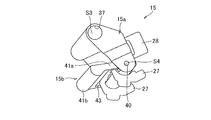
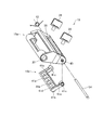
次に、ダンパ部15の構成について図19A,図19B~図22を参照して説明する。図19Aはダンパ部及びダンパ支持部材を斜め上方から見た斜視図である。図19Bはダンパ部を斜め下方から見た斜視図である。図20はダンパ部及びダンパ支持部材を上方から見た斜視図である。図21はアウターダンパ部の分解斜視図である。図22はアウターダンパ部とインナーダンパ部との分解斜視図である。
アウターダンパ部15aを側面から見て長手方向一端側(上端部側)には、軸受け孔部37が形成されている。この軸受け孔部37内には揺動軸S3が挿入されている。これにより、アウターダンパ部15aは揺動軸S3を中心に揺動自在の状態で軸支されている。すなわち、アウターダンパ部15aは、その長手方向他端部(下端部)が揺動軸S3を中心にして連続紙Pに加わる応力を緩和できるように上下方向に揺動自在の状態で軸支されている。
また、アウターダンパ部15aの、プリンタ1における背面側の表面には、スライド孔部38が揺動軸S3の軸方向に沿って形成されている。このスライド孔部38には、2個のガイド操作部28の軸部が挿入されている。このガイド操作部28の軸部には、ピン39(図19A及び図19B参照)により幅調整ガイド部27が接続されている。ここでは、例えば、奥側のガイド操作部28は固定されている。また、手前側のガイド操作部28はスライド孔部38に沿って移動することが可能になっているとともに、連続紙Pの幅に合わせて固定することが可能になっている。なお、幅調整ガイド部27及びガイド操作部28については後ほど詳細に説明する。
また、アウターダンパ部15aを側面から見て搬送方向上流側の端部側において連続紙Pが接する用紙接触部は、アウターダンパ部15aを側面側から見て円弧状に形成されている。これにより、アウターダンパ部15aと連続紙Pとの接触抵抗を下げることができるので、連続紙Pの流れをスムーズにすることができる。
また、アウターダンパ部15aの搬送方向上流側の端部側には、軸受け孔部40が形成されている。この軸受け孔部40内には揺動軸S4が揺動しないように固定された状態で挿入されている。揺動軸S4は揺動軸S3に対して平行に配置されている。この揺動軸S4にはインナーダンパ部15bが軸支されている。
インナーダンパ部15bは、2箇所の支持部41a,41aと、それらの一端側にそれらを橋渡すように一体形成された本体部41bと、を有している。支持部41a,41aの一端には、軸受け孔部41cが形成されている。この軸受け孔部41c,41c内には揺動軸S4が挿入されている。これにより、インナーダンパ部15bは揺動軸S4を中心にして揺動自在の状態で軸支されている。
また、揺動軸S4の一端側には、トーションバネ42(図20及び図22参照)がインナーダンパ部15bに係合された状態で装着されている。このトーションバネ42の付勢力により、インナーダンパ部15bは、その下端部(用紙接触部)が、連続紙Pに働く応力を緩和できるように、上下方向に揺動自在の状態で揺動軸S4に軸支されている。
一方、インナーダンパ部15bの本体部41bにおいて連続紙Pに接する用紙接触部側は、インナーダンパ部15bを側面から見て円弧状に形成されている。これにより、インナーダンパ部15bと連続紙Pとの接触抵抗を下げることができるので、連続紙Pの流れをスムーズすることができる。
また、本体部41bにおいて用紙接触部の反対面側には、窪み部41dが形成されている。この窪み部41d内には、揺動軸S4の軸方向に沿って予め決められた間隔毎に複数枚の補強板41eが配置されている。これにより、インナーダンパ部15bの強度を確保したまま、インナーダンパ部15bを軽量化することができる。
また、ダンパ機能を全く別個に設けることも考えられるが、その場合、ダンパ部15付近のスペースに制限があるので、プリンタ1の大型化を招く場合がある。これに対して本実施の形態においては、インナーダンパ部15bをアウターダンパ部15aに軸支したことにより、プリンタ1の大型化を招くことなく、裏巻きラベルの場合でも連続紙Pに働く応力を充分に緩和することが可能なダンパ機能を追加することができる。
さらに、本実施の形態においては、上記のようなアウターダンパ部15a及びインナーダンパ部15bが、例えば、透明な樹脂により構成されている。これにより、ダンパ部15での連続紙Pの視認性を向上させることができるので、連続紙Pをプリンタ1の通紙ルートにセットする作業をさらに容易にすることができる。すなわち、透明なダンパ部を解して不透明な幅調整ガイド部27の位置を確認し、簡単に位置調整を行うことができる。このような観点から、透明とは、当該部材の向こう側が視認可能であることを指し、透明な材料とは、無着色な材料は勿論のこと、着色された半透明な材料や無着色でも半透明な材料も含むものとする。
なお、インナーダンパ部15bの本体部41bとアウターダンパ部15aとの間には、幅調整ガイド部27の移動を遮らないように隙間43(図19B及び図20参照)が形成されている。
次に、ダンパ部15による作用効果について図23A,図23B~図25A,図25Bを参照して説明する。
図23Aは表巻きラベルの連続紙をセットした場合におけるダンパ部の拡大側面図である。図23Bは裏巻きラベルの連続紙をセットした場合におけるダンパ部の拡大側面図である。
図23Aに示すように、表巻きラベルの場合は、連続紙Psが用紙供給部10の高さ方向中央あたりから繰り出されダンパ部15の下に通されるので、アウターダンパ部15a及びインナーダンパ部15bの両方に接触した状態で通紙ルートにセットされる。このため、連続紙Psに働く応力を充分に緩和することができるので、連続紙Psを良好に搬送でき、印字品質を確保することができる。
一方、裏巻きラベルの場合、特に裏巻きラベルの直径が大きい状態の場合は、連続紙Pがプリンタ1の内部底面あたりから繰り出されダンパ部15の下に通されるので、アウターダンパ部15aのみが配置されている場合(インナーダンパ部15bが無い場合)は、通紙ルートにセットされる連続紙Pに働く応力を充分に緩和できない場合がある。このため、連続紙Pを上手く搬送できず印字品質が劣化する場合がある。
これに対して、本実施の形態においては、図23Bに示すように、裏巻きラベルや表巻きラベルなどのラベルの形態やロールラベルの直径の大小によって通紙ルートが異なる場合であっても連続紙Pbが少なくともインナーダンパ部15bに接触した状態で通紙ルートにセットされ、連続紙Pbに働く応力を充分に緩和することができるので、連続紙Pbを良好に搬送でき、印字品質を確保することができる。
図24Aは、連続紙を通紙ルートにセットする前段階のダンパ部の側面図である。
図24Bは、表巻きラベルの場合であって用紙供給部10のロール状の連続紙Psが少なくなりロール状の連続紙Psの外周部が支持軸10aに近づいた段階(ロール径が小さい)を例示している。この場合、連続紙Psの繰り出し位置が初期段階よりも低くなるので、アウターダンパ部15aに対する連続紙Psの押圧力が弱くなりアウターダンパ部15aの高さは変わらないが、インナーダンパ部15bが持ち上がり、連続紙Psに働く搬送方向とは逆方向に引っ張られる力による衝撃を緩和することができる。
図24Cは、裏巻きラベルの場合であって用紙供給部10のロール状の連続紙Pbが初期段階(ロール径が大きい)の場合を例示している。この場合、連続紙Pbの繰り出し位置が低く(プリンタ1の底面に近く)なるので、連続紙Pbがアウターダンパ部15aに接するものの押圧力が弱くアウターダンパ部15aの高さは変わらないが、インナーダンパ部15bが持ち上がり、連続紙Pbに働く搬送方向とは逆方向に引っ張られる力による衝撃を緩和することができる。
図25Aは、表巻きラベルの場合であって用紙供給部10のロール状の連続紙Psが初期段階(ロール径が大きい)の場合を例示している。この場合、連続紙Psの繰り出し位置が高いので、アウターダンパ部15a及びインナーダンパ部15bの両方が持ち上がり、連続紙Psに働く搬送方向とは逆方向に引っ張られる力による衝撃を緩和することができる。
図25Bは、裏巻きラベルの場合であって用紙供給部10のロール状の連続紙Pbが少なくなりロール状の連続紙Pbの外周部が支持軸10aに近づいた場合(ロール径が小さい)を例示している。この場合、連続紙Pbの繰り出し位置が初期段階よりも高くなるので、アウターダンパ部15a及びインナーダンパ部15bの両方が持ち上がり、連続紙Pbに働く搬送方向とは逆方向に引っ張られる力による衝撃を緩和することができる。
次に、幅調整ガイド部27及びガイド操作部28について、図26~図30を参照して説明する。図26はプリンタ1の正面側から見たアウターダンパ部の斜視図である。図27は図26からアウターダンパ部を抜き出して示した斜視図である。図28は図26から幅調整ガイド部及びガイド操作部28を抜き出して示した斜視図である。図29は幅調整ガイド部とガイド操作部との接続部を示した斜視図である。図30はガイド操作部の軸部と幅調整ガイド部との係合部分の斜視図である。なお、図30ではガイド操作部28の軸部28aを見易くするためにピン39を省略している。
図26及び図27に示すように、アウターダンパ部15aの内側には、2つのガイドレール部45がスライド孔部38の上下を挟むようにスライド孔部38に沿って延在した状態で形成されている。ガイドレール部45は、アウターダンパ部15aと一体に成形されており、例えば、透明な樹脂により形成されている。
図28に示すように、幅調整ガイド部27とガイド操作部28とを接続するピン39は、アウターダンパ部15aの2つのガイドレール部45に挟まれた位置に配置されている。ピン39の外周には、図26、図28及び図29に示すように、2つの凸部39a,39aが径方向に突出形成されている。凸部39a,39aは、互いに180度離れた反対の位置に形成されている。
ガイド操作部28を摘んで軸部28aを中心に揺動させると、ピン39も揺動するようになっている。そして、ピン39の揺動位置によりピン39の2つの凸部39a,39aが2つのガイドレール部45の内側の面に押し付けられることにより、ガイドレール部45が撓んで、ピン39が2つのガイドレール部45間に当接して挟みこまれることで固定されるようになっている。これにより、ガイド操作部28がロックされる。一方、ロック状態からガイド操作部28をさらに90度揺動させると、ピン39の2つの凸部39a,39aが2つのガイドレール部45から離れるので、ガイド操作部28のロック状態が解除される。したがって、本実施の形態においては、簡単な構造で、かつ、簡単な操作で、幅調整ガイド部27の位置を設定することができる。
また、図30に示すように、ガイド操作部28の軸部28aの外周には凸部28bが形成されている。幅調整ガイド部27においてガイド操作部28の軸部28aが挿入される孔27aの外周には、範囲設定孔27bが孔27aに連通した状態で形成されている。凸部28bは、その範囲設定孔27b内に配置されており、その範囲設定孔27bの周方向の範囲θでガイド操作部28を揺動させることが可能になっている。
次に、ダンパ部15の幅調整ガイド部27の下方に位置するプリンタ1の内部底面に窪み部29を設けたことによる作用効果を図23A,図23B等を参照して説明する。
プリンタ1で印字する際に、連続紙Pは、用紙供給部10側から印字部11側に、すなわち搬送方向上流側から下流側に向けて搬送される(フォワードフィードという)。一方、連続紙Pは、印字開始位置の位置合わせ行うために、印字部11側から用紙供給部10側に、すなわち搬送方向下流側から上流側に向けて搬送される場合もある(バックフィードという)。
フォワードフィードの場合、図21等に開示されるように、用紙供給部10から印字部11間に掛け渡された連続紙Pは、プリンタ1の内部底面から離れた位置に配置される。この状態で、連続紙Pには、常に、張力が付与されている。
しかしながら、バックフィードの場合、連続紙Pが弛み、プリンタ1の内部底面における幅調整ガイド部27に対応する位置で連続紙Pがプリンタ1の内部底面に接触することがある。このとき、仮に窪み部29を設けなかった場合、連続紙Pが幅調整ガイド部27とプリンタ1の内部底面の隙間から幅調整ガイド部27の下端を乗り越え、幅調整ガイド部27によって規制されるガイド領域の外に出てしまう場合がある。そして、その状態で、フォワードフィードによる印字動作に戻ると、ダンパ部15が機能しない状態で連続紙Pが搬送される。その結果、印字位置が予定位置からずれたり、印字濃度が薄くなったりして、印字品質が低下する問題がある。特に、幅の短い連続紙の場合には、幅調整ガイド部から外れることが多い。
これに対して本実施の形態においては、プリンタ1の内部底面に窪み部29を設けている。窪み部29の底面は、プリンタ1の内部底面よりも下方に位置する。また、連続紙Pは、自身の剛性によって、窪み部29の上流側と下流側とを橋渡しするように配置される。この構成のため、連続紙Pが印字部11から用紙供給部10側へバックフィードされると、連続紙Pは、プリンタ1の内部底面に当接するが、窪み部29の底面には接触することがない。
このため、連続紙Pがプリンタ1の内部底面に当接する状態であっても、窪み部29においては、幅調整ガイド部27の下端が、連続紙Pよりも窪み部29の底面に近い位置にある。このため、連続紙Pが幅調整ガイド部27の下端を乗り越え、幅調整ガイド部27によって規制されるガイド領域の外に出てしまうことがない。このため、フォワードフィードによる印字動作に戻った場合に、連続紙Pが幅調整ガイド部27に乗り上げることもなく、ダンパ部15の機能が損なわれることもない。したがって、印字位置が予定位置からずれたり、印字濃度が薄くなったりする不具合を回避することができるので、プリンタ1の印字品質を確保することができる。
窪み部29の断面形状は、搬送方向上流側の傾斜が搬送方向下流側の傾斜よりも緩やかになるように形成されている。ただし、窪み部29の内壁面は、プリンタ1の内部底面に対してほぼ垂直になっていても良い。
また、窪み部29を含むプリンタ1の内部底面に連続紙Pの搬送方向に沿って延びる複数の突部(図示せず)を連続紙Pの幅方向に沿って所定間隔を空けて配置しても良い。これらにより、バックフィード時に連続紙Pの流れをスムーズにすることができるので、ダンパ部15の下方で連続紙Pが詰まる不具合を低減又は防止することができる。
次に、連続紙Pをプリンタ1の通紙ルートにセットする作業について図8及び図9等を参照して説明する。
まず、図8に示す印字部11のヘッドロックレバー部16を図8の右方向に引くと、その動作に連動してロック爪部22が右方向に移動してピン20から外れる。すると、図9に示すように、印字ヘッド部13の前方部が上方に開くとともに、その動作に連動してダンパ支持部材25の後方部が持ち上がり、ダンパ部15も持ち上がる。これにより、ダンパ部15の下方の間口を広げることができる。
続いて、用紙供給部10から繰り出された連続紙Pをダンパ部15の下にくぐらせ、印字ヘッド部13と支持台14との間に通す。この際、ダンパ部15が持ち上がり開いているので、連続紙Pのセット作業を容易にすることができる。
その後、図8に示すように、印字ヘッド部13の前方部を押し下げ、印字ヘッド部13を閉めると、印字ヘッド部13が閉止位置に移動した後、ダンパ支持部材25の後方部がトーションバネ30の付勢力によって、プリンタ1の内部底面方向に下がり、ダンパ部15も同方向に移動する。
これにより、連続紙Pは、ダンパ部15が当接するよりも先に、印字ヘッド部13とプラテンローラ部23により挟持して押さえられる。このため、ダンパ部15が閉止状態に移動する際に、連続紙Pがダンパ部15に引っ張られてプラテンローラ部23上から外れる(位置ずれが生じる)ことがない。
以上、本発明の実施形態について説明したが、上記実施形態は、本発明の適用例の一部を示したに過ぎず、本発明の技術的範囲を上記実施形態の具体的構成に限定する趣旨ではない。
例えば、前記実施の形態においては、印字媒体として複数枚のラベルを台紙に仮着した連続紙を用いた場合について説明したが、これに限定されるものではなく、例えば、一方面に粘着面を有する連続状のラベル(台紙無しラベル)、粘着面を有しない連続状のシート(連続シート)あるいは紙類に限らずサーマルヘッドにより印字可能なフィルム等を印字媒体として使用することもできる。台紙無しラベル、連続シート又はフィルムは位置検出マークを有することができる。また、粘着剤が露出する台紙無しラベルなどを搬送する場合には、搬送路を非粘着コーティングするとともにシリコーンを含有したローラを設けることができる。
本願は、2016年10月4日に日本国特許庁に出願された特願2016-196619に基づく優先権を主張し、この出願の全ての内容は参照により本明細書に組み込まれる。
Claims (3)
- 長尺帯状の連続紙に印字を行うプリンタであって、
前記連続紙を搬送するプラテンローラ部と、
前記プラテンローラ部に対向する閉止位置及び前記プラテンローラ部から離間した開放位置に移動自在に設けられ、前記連続紙に印字を行う印字ヘッド部と、
前記印字ヘッド部の前記連続紙の搬送方向における上流側に設けられ、前記連続紙に当接する閉止位置及び前記連続紙から離間する開放位置に移動自在で、前記連続紙に加わる応力を緩和するダンパ部と、を備え、
前記印字ヘッド部が前記プラテンローラ部に対向する閉止位置にありかつ前記ダンパ部が前記連続紙に当接する閉止位置にある状態から、前記印字ヘッド部が前記プラテンローラ部から離間した開放位置にありかつ前記ダンパ部が前記連続紙から離間する開放位置にある状態に移行する場合には、前記印字ヘッド部が開放位置へ移動すると、前記印字ヘッド部に連動して前記ダンパ部が開放位置へ移動し、
前記印字ヘッド部が前記プラテンローラ部から離間した開放位置にありかつ前記ダンパ部が前記連続紙から離間する開放位置にある状態から、前記印字ヘッド部が前記プラテンローラ部に対向する閉止位置にありかつ前記ダンパ部が前記連続紙に当接する閉止位置にある状態に移行する場合には、前記印字ヘッド部が閉止位置へ移動した後、前記ダンパ部が閉止位置に移動する、プリンタ。 - 請求項1に記載のプリンタであって、
前記ダンパ部を閉止位置に向かう方向に付勢する付勢部材と、
前記ダンパ部を開放位置に係止する係止部材と、を備え、
前記印字ヘッド部が前記プラテンローラ部から離間した開放位置にありかつ前記ダンパ部が前記連続紙から離間する開放位置にある状態から、前記印字ヘッド部が前記プラテンローラ部に対向する閉止位置にありかつ前記ダンパ部が前記連続紙に当接する閉止位置にある状態に移行する場合に、前記印字ヘッド部が閉止位置へ移動した後に、前記係止部材による前記ダンパ部の係止が解除される、プリンタ。 - 請求項1又は2に記載のプリンタであって、
前記印字ヘッド部は、
前記印字ヘッド部を支持する第1の支持体と、
前記第1の支持体を揺動自在に支持する印字ヘッド部支持軸と、
前記印字ヘッド部支持軸に対して前記連続紙の搬送方向上流側に位置し、前記ダンパ部の特定箇所に係合する係合部を有する係合端部とを備え、
前記ダンパ部は、
前記ダンパ部を支持する第2の支持体と、
前記第2の支持体を揺動自在に支持するダンパ支持軸と、
前記印字ヘッド部における前記係合部が係合する溝部と、
前記ダンパ部を閉止位置に向かう方向に付勢する付勢部材と、
前記ダンパ部を開放位置に係止する係止部材と、を備え、
前記溝部は、
前記ダンパ部が前記連続紙に当接する閉止位置において、前記印字ヘッド部支持軸を中心とする前記第1の支持体の揺動によって移動する前記係合部の移動軌跡に沿う形状に形成された第1溝と、
前記ダンパ部が前記連続紙から離間する開放位置において、前記印字ヘッド部支持軸を中心とする前記第1の支持体の揺動によって移動する前記係合部の移動軌跡に沿う形状に形成されており、前記第1溝の端部側から前記第1溝とは異なる経路で形成された第2溝と、
前記第1の支持体が閉止位置に位置する状態において、前記ダンパ支持軸を中心として前記係合部までの距離を半径とする円弧形状に形成されており、前記第1溝の端部側と前記第2溝の端部側とを連結する第3溝とを有する、プリンタ。
Priority Applications (5)
| Application Number | Priority Date | Filing Date | Title |
|---|---|---|---|
| MYPI2018002280A MY190731A (en) | 2016-10-04 | 2017-04-14 | Printer |
| US16/076,562 US10710385B2 (en) | 2016-10-04 | 2017-04-14 | Printer |
| EP17857995.9A EP3401110B1 (en) | 2016-10-04 | 2017-04-14 | Printer |
| CN201780032070.7A CN109414942B (zh) | 2016-10-04 | 2017-04-14 | 打印机 |
| JP2018543579A JP6895448B2 (ja) | 2016-10-04 | 2017-04-14 | プリンタ |
Applications Claiming Priority (2)
| Application Number | Priority Date | Filing Date | Title |
|---|---|---|---|
| JP2016196619 | 2016-10-04 | ||
| JP2016-196619 | 2016-10-04 |
Publications (1)
| Publication Number | Publication Date |
|---|---|
| WO2018066155A1 true WO2018066155A1 (ja) | 2018-04-12 |
Family
ID=61831646
Family Applications (1)
| Application Number | Title | Priority Date | Filing Date |
|---|---|---|---|
| PCT/JP2017/015309 Ceased WO2018066155A1 (ja) | 2016-10-04 | 2017-04-14 | プリンタ |
Country Status (6)
| Country | Link |
|---|---|
| US (1) | US10710385B2 (ja) |
| EP (1) | EP3401110B1 (ja) |
| JP (1) | JP6895448B2 (ja) |
| CN (1) | CN109414942B (ja) |
| MY (1) | MY190731A (ja) |
| WO (1) | WO2018066155A1 (ja) |
Families Citing this family (8)
| Publication number | Priority date | Publication date | Assignee | Title |
|---|---|---|---|---|
| JP6895447B2 (ja) * | 2016-10-04 | 2021-06-30 | サトーホールディングス株式会社 | プリンタ |
| JP7423976B2 (ja) * | 2019-10-24 | 2024-01-30 | ブラザー工業株式会社 | 印刷装置 |
| EP3838604B1 (de) | 2019-12-18 | 2022-03-30 | Bizerba SE & Co. KG | Etikettendrucker |
| EP3838602B1 (de) | 2019-12-18 | 2022-03-30 | Bizerba SE & Co. KG | Etikettendrucker |
| ES2911269T3 (es) | 2019-12-18 | 2022-05-18 | Bizerba Se & Co Kg | Impresora de etiquetas |
| ES2915847T3 (es) | 2019-12-18 | 2022-06-27 | Bizerba Se & Co Kg | Impresora de etiquetas |
| USD1087216S1 (en) * | 2022-07-11 | 2025-08-05 | Zebra Technology Corporation | Media processing device |
| JP1747031S (ja) * | 2022-10-04 | 2023-06-22 | ラベルプリンタ |
Citations (4)
| Publication number | Priority date | Publication date | Assignee | Title |
|---|---|---|---|---|
| JPS61266277A (ja) * | 1985-05-21 | 1986-11-25 | Tokyo Electric Co Ltd | サ−マル転写プリンタ |
| JP2007210264A (ja) * | 2006-02-13 | 2007-08-23 | Sato Corp | プリンタ |
| US20100103238A1 (en) * | 2008-10-23 | 2010-04-29 | Avery Dennison Corporation | Hand-held portable printer system and method |
| JP2015123626A (ja) * | 2013-12-26 | 2015-07-06 | サトーホールディングス株式会社 | プリンタ |
Family Cites Families (24)
| Publication number | Priority date | Publication date | Assignee | Title |
|---|---|---|---|---|
| JPH0811461B2 (ja) | 1987-06-30 | 1996-02-07 | セイコーエプソン株式会社 | プリンタの紙送り機構 |
| US5221150A (en) | 1987-06-30 | 1993-06-22 | Seiko Epson Corporation | Paper feeding apparatus for printers having a bail roller means |
| JPH08157120A (ja) | 1994-12-02 | 1996-06-18 | Mitsubishi Electric Corp | プリンタ装置 |
| JPH09150981A (ja) * | 1995-11-30 | 1997-06-10 | Tec Corp | 給紙装置 |
| JPH11246092A (ja) | 1998-03-02 | 1999-09-14 | Toshiba Tec Corp | 長尺部材搬送装置 |
| JP2000052613A (ja) * | 1998-08-06 | 2000-02-22 | Toshiba Tec Corp | ラベルプリンタ |
| JP2007126230A (ja) | 2005-11-01 | 2007-05-24 | Tohoku Ricoh Co Ltd | 熱転写プリンタ |
| JP2007301869A (ja) | 2006-05-12 | 2007-11-22 | Ishida Co Ltd | プリンタ |
| JP2009101656A (ja) * | 2007-10-25 | 2009-05-14 | Fujitsu Component Ltd | プリンタ装置 |
| JP5272147B2 (ja) | 2008-09-24 | 2013-08-28 | サトーホールディングス株式会社 | 用紙供給装置 |
| JP5063545B2 (ja) | 2008-09-24 | 2012-10-31 | 株式会社サトー知識財産研究所 | プリンタ |
| WO2010035357A1 (ja) | 2008-09-24 | 2010-04-01 | 株式会社サトー | ラベル貼付装置 |
| JP4886050B2 (ja) | 2009-02-10 | 2012-02-29 | 東芝テック株式会社 | ラベルプリンタ |
| JP4885990B2 (ja) * | 2009-02-10 | 2012-02-29 | 東芝テック株式会社 | ラベルプリンタ |
| CN101830116A (zh) * | 2009-03-13 | 2010-09-15 | 李解平 | 带有张力器和色带驱动器的打印机的打印头座的驱动装置 |
| JP5445028B2 (ja) * | 2009-10-23 | 2014-03-19 | セイコーエプソン株式会社 | プラテン支持機構およびロール紙プリンター |
| JP5576138B2 (ja) | 2010-02-10 | 2014-08-20 | シチズンホールディングス株式会社 | サーマルプリンタ |
| JP2013052611A (ja) * | 2011-09-05 | 2013-03-21 | Toshiba Tec Corp | プリンタ |
| JP2013052612A (ja) | 2011-09-05 | 2013-03-21 | Toshiba Tec Corp | プリンタ |
| JP6282462B2 (ja) | 2013-12-26 | 2018-02-21 | サトーホールディングス株式会社 | プリンタ |
| JP6594605B2 (ja) | 2013-12-26 | 2019-10-23 | サトーホールディングス株式会社 | プリンタ |
| JP6755635B2 (ja) * | 2013-12-26 | 2020-09-16 | サトーホールディングス株式会社 | プリンタ |
| JP6309266B2 (ja) | 2013-12-26 | 2018-04-11 | サトーホールディングス株式会社 | プリンタ |
| JP6460761B2 (ja) | 2014-12-03 | 2019-01-30 | サトーホールディングス株式会社 | プリンタ |
-
2017
- 2017-04-14 JP JP2018543579A patent/JP6895448B2/ja active Active
- 2017-04-14 EP EP17857995.9A patent/EP3401110B1/en active Active
- 2017-04-14 US US16/076,562 patent/US10710385B2/en active Active
- 2017-04-14 CN CN201780032070.7A patent/CN109414942B/zh active Active
- 2017-04-14 WO PCT/JP2017/015309 patent/WO2018066155A1/ja not_active Ceased
- 2017-04-14 MY MYPI2018002280A patent/MY190731A/en unknown
Patent Citations (4)
| Publication number | Priority date | Publication date | Assignee | Title |
|---|---|---|---|---|
| JPS61266277A (ja) * | 1985-05-21 | 1986-11-25 | Tokyo Electric Co Ltd | サ−マル転写プリンタ |
| JP2007210264A (ja) * | 2006-02-13 | 2007-08-23 | Sato Corp | プリンタ |
| US20100103238A1 (en) * | 2008-10-23 | 2010-04-29 | Avery Dennison Corporation | Hand-held portable printer system and method |
| JP2015123626A (ja) * | 2013-12-26 | 2015-07-06 | サトーホールディングス株式会社 | プリンタ |
Non-Patent Citations (1)
| Title |
|---|
| See also references of EP3401110A4 * |
Also Published As
| Publication number | Publication date |
|---|---|
| US10710385B2 (en) | 2020-07-14 |
| MY190731A (en) | 2022-05-12 |
| EP3401110A4 (en) | 2019-05-22 |
| CN109414942A (zh) | 2019-03-01 |
| EP3401110B1 (en) | 2022-08-03 |
| EP3401110A1 (en) | 2018-11-14 |
| JPWO2018066155A1 (ja) | 2019-07-25 |
| CN109414942B (zh) | 2021-09-14 |
| JP6895448B2 (ja) | 2021-06-30 |
| US20190061393A1 (en) | 2019-02-28 |
Similar Documents
| Publication | Publication Date | Title |
|---|---|---|
| WO2018066155A1 (ja) | プリンタ | |
| JP6244200B2 (ja) | プリンタ | |
| WO2015099061A1 (ja) | プリンタ | |
| WO2015099057A1 (ja) | プリンタ | |
| JP6895447B2 (ja) | プリンタ | |
| WO2015099056A1 (ja) | プリンタ | |
| JP6698801B2 (ja) | プリンタ | |
| JP6449967B2 (ja) | プリンタ | |
| JP6970159B2 (ja) | プリンタ | |
| JP6632700B2 (ja) | プリンタ | |
| JP6770558B2 (ja) | プリンタ |
Legal Events
| Date | Code | Title | Description |
|---|---|---|---|
| WWE | Wipo information: entry into national phase |
Ref document number: 2017857995 Country of ref document: EP |
|
| WWE | Wipo information: entry into national phase |
Ref document number: 2018543579 Country of ref document: JP |
|
| ENP | Entry into the national phase |
Ref document number: 2017857995 Country of ref document: EP Effective date: 20180809 |
|
| NENP | Non-entry into the national phase |
Ref country code: DE |