WO2018066464A1 - 駆動源制御装置 - Google Patents
駆動源制御装置 Download PDFInfo
- Publication number
- WO2018066464A1 WO2018066464A1 PCT/JP2017/035440 JP2017035440W WO2018066464A1 WO 2018066464 A1 WO2018066464 A1 WO 2018066464A1 JP 2017035440 W JP2017035440 W JP 2017035440W WO 2018066464 A1 WO2018066464 A1 WO 2018066464A1
- Authority
- WO
- WIPO (PCT)
- Prior art keywords
- drive
- source control
- control device
- angular acceleration
- torque
- Prior art date
- Legal status (The legal status is an assumption and is not a legal conclusion. Google has not performed a legal analysis and makes no representation as to the accuracy of the status listed.)
- Ceased
Links
Images




Classifications
-
- B—PERFORMING OPERATIONS; TRANSPORTING
- B60—VEHICLES IN GENERAL
- B60L—PROPULSION OF ELECTRICALLY-PROPELLED VEHICLES; SUPPLYING ELECTRIC POWER FOR AUXILIARY EQUIPMENT OF ELECTRICALLY-PROPELLED VEHICLES; ELECTRODYNAMIC BRAKE SYSTEMS FOR VEHICLES IN GENERAL; MAGNETIC SUSPENSION OR LEVITATION FOR VEHICLES; MONITORING OPERATING VARIABLES OF ELECTRICALLY-PROPELLED VEHICLES; ELECTRIC SAFETY DEVICES FOR ELECTRICALLY-PROPELLED VEHICLES
- B60L15/00—Methods, circuits, or devices for controlling the traction-motor speed of electrically-propelled vehicles
- B60L15/20—Methods, circuits, or devices for controlling the traction-motor speed of electrically-propelled vehicles for control of the vehicle or its driving motor to achieve a desired performance, e.g. speed, torque, programmed variation of speed
- B60L15/2036—Electric differentials, e.g. for supporting steering vehicles
-
- B—PERFORMING OPERATIONS; TRANSPORTING
- B60—VEHICLES IN GENERAL
- B60L—PROPULSION OF ELECTRICALLY-PROPELLED VEHICLES; SUPPLYING ELECTRIC POWER FOR AUXILIARY EQUIPMENT OF ELECTRICALLY-PROPELLED VEHICLES; ELECTRODYNAMIC BRAKE SYSTEMS FOR VEHICLES IN GENERAL; MAGNETIC SUSPENSION OR LEVITATION FOR VEHICLES; MONITORING OPERATING VARIABLES OF ELECTRICALLY-PROPELLED VEHICLES; ELECTRIC SAFETY DEVICES FOR ELECTRICALLY-PROPELLED VEHICLES
- B60L15/00—Methods, circuits, or devices for controlling the traction-motor speed of electrically-propelled vehicles
- B60L15/20—Methods, circuits, or devices for controlling the traction-motor speed of electrically-propelled vehicles for control of the vehicle or its driving motor to achieve a desired performance, e.g. speed, torque, programmed variation of speed
-
- B—PERFORMING OPERATIONS; TRANSPORTING
- B60—VEHICLES IN GENERAL
- B60L—PROPULSION OF ELECTRICALLY-PROPELLED VEHICLES; SUPPLYING ELECTRIC POWER FOR AUXILIARY EQUIPMENT OF ELECTRICALLY-PROPELLED VEHICLES; ELECTRODYNAMIC BRAKE SYSTEMS FOR VEHICLES IN GENERAL; MAGNETIC SUSPENSION OR LEVITATION FOR VEHICLES; MONITORING OPERATING VARIABLES OF ELECTRICALLY-PROPELLED VEHICLES; ELECTRIC SAFETY DEVICES FOR ELECTRICALLY-PROPELLED VEHICLES
- B60L9/00—Electric propulsion with power supply external to the vehicle
- B60L9/16—Electric propulsion with power supply external to the vehicle using AC induction motors
- B60L9/18—Electric propulsion with power supply external to the vehicle using AC induction motors fed from DC supply lines
-
- B—PERFORMING OPERATIONS; TRANSPORTING
- B60—VEHICLES IN GENERAL
- B60W—CONJOINT CONTROL OF VEHICLE SUB-UNITS OF DIFFERENT TYPE OR DIFFERENT FUNCTION; CONTROL SYSTEMS SPECIALLY ADAPTED FOR HYBRID VEHICLES; ROAD VEHICLE DRIVE CONTROL SYSTEMS FOR PURPOSES NOT RELATED TO THE CONTROL OF A PARTICULAR SUB-UNIT
- B60W10/00—Conjoint control of vehicle sub-units of different type or different function
- B60W10/04—Conjoint control of vehicle sub-units of different type or different function including control of propulsion units
- B60W10/08—Conjoint control of vehicle sub-units of different type or different function including control of propulsion units including control of electric propulsion units, e.g. motors or generators
-
- B—PERFORMING OPERATIONS; TRANSPORTING
- B60—VEHICLES IN GENERAL
- B60W—CONJOINT CONTROL OF VEHICLE SUB-UNITS OF DIFFERENT TYPE OR DIFFERENT FUNCTION; CONTROL SYSTEMS SPECIALLY ADAPTED FOR HYBRID VEHICLES; ROAD VEHICLE DRIVE CONTROL SYSTEMS FOR PURPOSES NOT RELATED TO THE CONTROL OF A PARTICULAR SUB-UNIT
- B60W30/00—Purposes of road vehicle drive control systems not related to the control of a particular sub-unit, e.g. of systems using conjoint control of vehicle sub-units
- B60W30/02—Control of vehicle driving stability
- B60W30/045—Improving turning performance
-
- F—MECHANICAL ENGINEERING; LIGHTING; HEATING; WEAPONS; BLASTING
- F16—ENGINEERING ELEMENTS AND UNITS; GENERAL MEASURES FOR PRODUCING AND MAINTAINING EFFECTIVE FUNCTIONING OF MACHINES OR INSTALLATIONS; THERMAL INSULATION IN GENERAL
- F16H—GEARING
- F16H48/00—Differential gearings
- F16H48/06—Differential gearings with gears having orbital motion
- F16H48/10—Differential gearings with gears having orbital motion with orbital spur gears
-
- F—MECHANICAL ENGINEERING; LIGHTING; HEATING; WEAPONS; BLASTING
- F16—ENGINEERING ELEMENTS AND UNITS; GENERAL MEASURES FOR PRODUCING AND MAINTAINING EFFECTIVE FUNCTIONING OF MACHINES OR INSTALLATIONS; THERMAL INSULATION IN GENERAL
- F16H—GEARING
- F16H48/00—Differential gearings
- F16H48/36—Differential gearings characterised by intentionally generating speed difference between outputs
-
- G—PHYSICS
- G01—MEASURING; TESTING
- G01P—MEASURING LINEAR OR ANGULAR SPEED, ACCELERATION, DECELERATION, OR SHOCK; INDICATING PRESENCE, ABSENCE, OR DIRECTION, OF MOVEMENT
- G01P15/00—Measuring acceleration; Measuring deceleration; Measuring shock, i.e. sudden change of acceleration
- G01P15/16—Measuring acceleration; Measuring deceleration; Measuring shock, i.e. sudden change of acceleration by evaluating the time-derivative of a measured speed signal
- G01P15/165—Measuring acceleration; Measuring deceleration; Measuring shock, i.e. sudden change of acceleration by evaluating the time-derivative of a measured speed signal for measuring angular accelerations
-
- B—PERFORMING OPERATIONS; TRANSPORTING
- B60—VEHICLES IN GENERAL
- B60L—PROPULSION OF ELECTRICALLY-PROPELLED VEHICLES; SUPPLYING ELECTRIC POWER FOR AUXILIARY EQUIPMENT OF ELECTRICALLY-PROPELLED VEHICLES; ELECTRODYNAMIC BRAKE SYSTEMS FOR VEHICLES IN GENERAL; MAGNETIC SUSPENSION OR LEVITATION FOR VEHICLES; MONITORING OPERATING VARIABLES OF ELECTRICALLY-PROPELLED VEHICLES; ELECTRIC SAFETY DEVICES FOR ELECTRICALLY-PROPELLED VEHICLES
- B60L2220/00—Electrical machine types; Structures or applications thereof
- B60L2220/40—Electrical machine applications
- B60L2220/42—Electrical machine applications with use of more than one motor
-
- B—PERFORMING OPERATIONS; TRANSPORTING
- B60—VEHICLES IN GENERAL
- B60L—PROPULSION OF ELECTRICALLY-PROPELLED VEHICLES; SUPPLYING ELECTRIC POWER FOR AUXILIARY EQUIPMENT OF ELECTRICALLY-PROPELLED VEHICLES; ELECTRODYNAMIC BRAKE SYSTEMS FOR VEHICLES IN GENERAL; MAGNETIC SUSPENSION OR LEVITATION FOR VEHICLES; MONITORING OPERATING VARIABLES OF ELECTRICALLY-PROPELLED VEHICLES; ELECTRIC SAFETY DEVICES FOR ELECTRICALLY-PROPELLED VEHICLES
- B60L2240/00—Control parameters of input or output; Target parameters
- B60L2240/40—Drive Train control parameters
- B60L2240/42—Drive Train control parameters related to electric machines
- B60L2240/423—Torque
-
- B—PERFORMING OPERATIONS; TRANSPORTING
- B60—VEHICLES IN GENERAL
- B60W—CONJOINT CONTROL OF VEHICLE SUB-UNITS OF DIFFERENT TYPE OR DIFFERENT FUNCTION; CONTROL SYSTEMS SPECIALLY ADAPTED FOR HYBRID VEHICLES; ROAD VEHICLE DRIVE CONTROL SYSTEMS FOR PURPOSES NOT RELATED TO THE CONTROL OF A PARTICULAR SUB-UNIT
- B60W2710/00—Output or target parameters relating to a particular sub-units
- B60W2710/08—Electric propulsion units
- B60W2710/083—Torque
-
- Y—GENERAL TAGGING OF NEW TECHNOLOGICAL DEVELOPMENTS; GENERAL TAGGING OF CROSS-SECTIONAL TECHNOLOGIES SPANNING OVER SEVERAL SECTIONS OF THE IPC; TECHNICAL SUBJECTS COVERED BY FORMER USPC CROSS-REFERENCE ART COLLECTIONS [XRACs] AND DIGESTS
- Y02—TECHNOLOGIES OR APPLICATIONS FOR MITIGATION OR ADAPTATION AGAINST CLIMATE CHANGE
- Y02T—CLIMATE CHANGE MITIGATION TECHNOLOGIES RELATED TO TRANSPORTATION
- Y02T10/00—Road transport of goods or passengers
- Y02T10/60—Other road transportation technologies with climate change mitigation effect
- Y02T10/64—Electric machine technologies in electromobility
-
- Y—GENERAL TAGGING OF NEW TECHNOLOGICAL DEVELOPMENTS; GENERAL TAGGING OF CROSS-SECTIONAL TECHNOLOGIES SPANNING OVER SEVERAL SECTIONS OF THE IPC; TECHNICAL SUBJECTS COVERED BY FORMER USPC CROSS-REFERENCE ART COLLECTIONS [XRACs] AND DIGESTS
- Y02—TECHNOLOGIES OR APPLICATIONS FOR MITIGATION OR ADAPTATION AGAINST CLIMATE CHANGE
- Y02T—CLIMATE CHANGE MITIGATION TECHNOLOGIES RELATED TO TRANSPORTATION
- Y02T10/00—Road transport of goods or passengers
- Y02T10/60—Other road transportation technologies with climate change mitigation effect
- Y02T10/72—Electric energy management in electromobility
Definitions
- the present invention relates to a drive source control device, for example, a drive source control device for a vehicle drive device that amplifies a torque difference and transmits drive torque generated from two independent drive sources to left and right drive wheels.
- a vehicle drive device that includes a gear device that combines two planetary gear mechanisms between two drive sources and left and right drive wheels, and amplifies the difference in torque (Patent Documents 1 and 2). .
- Patent Document 3 a control device that corrects only the inertial force of the motor when the torque difference is generated is disclosed.
- Patent Document 3 the torque is corrected by calculating the inertia force from the difference between the rotational speeds of the left and right wheels and the moment of inertia of the motor.
- the vehicle drive device having the structure shown in Patent Documents 1 and 2, Since the rotational speed difference is caused by the rotational speed difference between the two motors, it is difficult to appropriately correct the torque with only the inertial force of one motor.
- An object of the present invention is to provide a drive source control device that can output a torque according to a given command value and stabilize vehicle behavior even when angular velocity changes occur in one or both of the left and right drive wheels. Is to provide.
- the drive source control device 67 of the present invention is a drive source control device 67 for controlling two drive sources 2L and 2R in a vehicle, and the vehicle is configured to have the two drive sources 2L and 2R and left and right drive wheels 61L. , 61R, and between the two drive sources 2L, 2R and the left and right drive wheels 61L, 61R, and distributes the power from the two drive sources 2L, 2R to the left and right drive wheels 61L, 61R.
- the drive source control device 67 is Angular acceleration calculating means 71 for obtaining at least one of the angular acceleration of the left and right drive wheels 61L, 61R and the angular acceleration of the drive sources 2L, 2R; Using the angular acceleration obtained by the angular acceleration calculating means 71, a correcting means 68 for correcting the command values for the outputs of the two drive sources 2L and 2R, which are given from the command means 66a, according to a predetermined condition.
- the predetermined condition is an arbitrary condition determined by design or the like, and is determined, for example, by obtaining an appropriate condition by one or both of a test and a simulation.
- the angular acceleration calculation means 71 obtains the angular acceleration of the drive wheels 61L and 61R or the drive sources 2L and 2R.
- the correction means 68 corrects the command values for the outputs of the two drive sources 2L and 2R given from the command means 66a according to the determined conditions, using the obtained angular acceleration. For example, when an angular acceleration is generated in one of the left and right driving wheels 61L and 61R, torque that is opposite to the angular acceleration is applied to the left and right driving wheels 61L and 61R.
- the command values for the outputs of the two drive sources 2L and 2R are corrected so as to be added to the other drive wheel 61R (61L).
- the correcting means 68 uses the angular acceleration obtained by the angular acceleration calculating means 71, and according to the predetermined moment of inertia of the rotating part and the number of gear teeth of the power transmission device 3, the two drive sources 2L, 2R.
- the command values for the respective outputs may be corrected.
- the predetermined rotating part is a rotating part (a rotating part or a rotating part) arbitrarily determined by design or the like, and is determined by determining an appropriate rotating part by one or both of testing and simulation, for example. According to this configuration, the correction unit 68 can correct the command values for the outputs of the two drive sources 2L and 2R so as to eliminate the influence of the inertial force.
- the power transmission device 3 may include a torque difference amplifying device 30.
- the torque difference amplifying device 30 includes two planetary gear mechanisms 30L and 30R, and amplifies a difference in torque generated by the two drive sources 2L and 2R. In this case, the torque difference amplifying device 30 amplifies the difference between the torques generated by the two drive sources 2L and 2R, thereby realizing a smooth turning of the vehicle. Even in a vehicle equipped with such a torque difference amplifying device 30, it is possible to output torque according to the command value given from the command means 66a.
- the correction means 68 uses the angular acceleration of at least one of the left and right drive wheels 61L and 61R to command the output of each of the two drive sources 2L and 2R. The value may be corrected.
- the correction means 68 may correct the command value for the output of each of the two drive sources 2L and 2R using the angular acceleration of the two drive sources 2L and 2R.
- the correcting means 68 When the angular acceleration is generated in any one of the left and right drive wheels 61L and 61R, the correcting means 68 generates a torque in a direction opposite to the angular acceleration when the left and right drive wheels 61L and 61R are in the opposite direction. You may correct
- the correcting means 68 applies a torque in the same direction as the angular acceleration to the one of the driving wheels 61L and 61R.
- the correction based on the inertial force can be performed on the driving wheel 61L (61R) in which the angular acceleration is generated so as to apply a torque in the same direction as the angular acceleration.
- the threshold value is a threshold value arbitrarily determined by design or the like. For example, the threshold value is determined by determining an appropriate threshold value by one or both of testing and simulation.
- the vehicle of the present invention is the vehicle, and includes the drive source control device 67.
- the drive source control device 67 In this case, even when an undesired change in angular velocity occurs in one or both of the left and right drive wheels 61L and 61R of the vehicle, torque according to the command value given from the command means 66a can be output. As a result, the vehicle behavior can be stabilized.
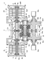
- FIG. 1 is a block diagram illustrating a conceptual configuration of a vehicle including a drive source control device according to a first embodiment of the present invention and a vehicle drive device. It is sectional drawing of the vehicle drive device of FIG. It is sectional drawing which expands and shows the torque difference amplifier apparatus part of the vehicle drive device of FIG. It is a skeleton figure which shows the vehicle drive device of FIG.
- FIG. 1 is a block diagram showing a conceptual configuration of a vehicle (electric vehicle) provided with the drive source control device and the vehicle drive device.
- This vehicle is a rear wheel drive system, and includes a chassis 60, rear drive wheels 61L and 61R, front wheels 62L and 62R, a vehicle drive device 1, a host ECU 66, a drive source control device 67, a battery 63, an inverter device 64, and the like. Is provided.
- the vehicle drive device 1 includes first and second electric motors 2L and 2R and a power transmission device 3.
- the first and second electric motors 2L and 2R are two drive sources mounted on the vehicle and independently controllable.
- the power transmission device is provided between the first and second electric motors 2L and 2R and the drive wheels 61L and 61R.
- the host ECU 66 is a host control unit of the drive source control device 67, and includes, for example, a function of performing overall control and cooperative control of the entire vehicle, and a function of generating braking / driving torque command values for the left and right drive wheels 61L and 61R.
- the host ECU 66 generates a right / left braking / driving torque from an acceleration command output from an unillustrated accelerator operation unit, a deceleration command output from an unshown brake operation unit, and a turning command output from a steering angle sensor (not shown).
- a command value (command value for output) is generated.
- the drive source control device 67 gives a motor torque command value to the inverter device 64 based on the left and right braking / driving torque command values given from the host ECU 66.
- the inverter device 64 converts the DC power of the battery 63 into AC power for driving the first and second electric motors 2L, 2R.
- the inverter device 64 controls the current supplied from the battery 63 so that the torque output from the first and second electric motors 2L and 2R is equal to the motor torque command value, and controls the first and second electric motors 2L and 2R.
- Drive The output from the vehicle drive device 1 is transmitted to the left and right drive wheels 61L and 61R through a constant velocity joint.
- the first and second electric motors 2L and 2R in the vehicle drive device 1 use the same standard electric motors having the same maximum output.
- the first and second electric motors 2L and 2R include motor housings 4L and 4R, stators 6 and 6, and rotors 5 and 5, respectively.
- the first and second electric motors 2L and 2R have radial gaps in which stators 6 and 6 are provided on the inner peripheral surfaces of the motor housings 4L and 4R, respectively, and a rotor 5 is provided on the inner periphery of each stator 6 with an interval.
- Type
- the motor housings 4L and 4R have cylindrical motor housing bodies 4aL and 4aR, outer walls 4bL and 4bR, and inner walls 4cL and 4cR, respectively.
- the outer side walls 4bL and 4bR close the outer surface on the outboard side of the motor housing main bodies 4aL and 4aR.
- the inner side walls 4cL and 4cR are provided on the inner side surface of the motor housing main bodies 4aL and 4aR on the inboard side, and form partition walls that are separated from the power transmission device 3.
- the inner walls 4cL and 4cR are provided with openings for pulling out the motor shafts 5a to the inboard side.
- the side closer to the outside in the vehicle width direction of the vehicle when the vehicle drive device 1 is mounted on the vehicle is referred to as the outboard side
- the side closer to the center in the vehicle width direction of the vehicle is referred to as the inboard. Call the side.
- the stators 6 and 6 are fitted and fixed to the inner peripheral surfaces of the motor housing bodies 4aL and 4aR, respectively.
- Each rotor 5 has a motor shaft 5a at the center.
- Each of the inner walls 4cL and 4cR is provided with a rolling bearing 8a, and each of the outer walls 4bL and 4bR is provided with a rolling bearing 8b.
- Each motor shaft 5a is rotatably supported by motor housings 4L and 4R via rolling bearings 8a and 8b.
- the left and right motor shafts 5a, 5a are provided on the same axis (coaxial).
- the power transmission device 3 includes a power transmission device housing 9.
- the power transmission device 3 further includes left and right input gear shafts 12L and 12R, left and right intermediate gear shafts 13L and 13R, left and right output gear shafts 14L and 14R, and a torque difference amplifying device 30.
- the power transmission device 3 amplifies the difference in torque (driving torque) input from the motor shaft 5a of the first and second electric motors 2L and 2R by the torque difference amplifying device 30 and drives the driving wheels 61L and 61R (FIG. 1). It is a device that transmits to
- the power transmission device housing 9 accommodates these gear shafts and the torque difference amplifying device 30.
- the power transmission device housing 9 has a three-piece structure divided into three pieces in a direction orthogonal to the axial direction of the gear shaft.
- the power transmission device housing 9 includes a central housing 9a and left and right side housings 9bL and 9bR fixed to both side surfaces of the central housing 9a.
- the side surface on the outboard side of the side housings 9bL and 9bR and the inner side walls 4cL and 4cR are fixed with a plurality of bolts.
- the two electric motors 2L and 2R are fixed to the left and right ends of the power transmission device housing 9.
- a partition wall 11 is provided in the center of the center housing 9a.
- the power transmission device housing 9 is divided into left and right parts by a partition wall 11, and these house the main body of the power transmission device 3.
- the main body portion of the power transmission device 3 is symmetrical, and includes the input gear shafts 12L and 12R, intermediate gear shafts 13L and 13R, output gear shafts 14L and 14R, and a torque difference amplifying device 30. Yes.
- the input gear shafts 12L and 12R have an input gear 12a to which power is transmitted from the motor shaft 5a.
- a rolling bearing 17a is provided in a bearing fitting hole formed in the partition wall 11, and a rolling bearing 17b is provided in a bearing fitting hole formed in the left and right side housings 9bL and 9bR. Both ends of the input gear shafts 12L and 12R are rotatably supported by the power transmission device housing 9 via rolling bearings 17a and 17b.
- the input gear shafts 12L and 12R have a hollow structure. The end portions on the inboard side of the motor shafts 5a are inserted into the hollow interiors of the input gear shafts 12L and 12R.
- the input gear shafts 12L, 12R and the motor shafts 5a are coupled by splines (including “serration”. The following splines also include “serration”).
- the left and right intermediate gear shafts 13L and 13R are arranged coaxially.
- the intermediate gear shafts 13L and 13R include large-diameter input-side external gears 13a and 13a that mesh with the input gears 12a and 12a, and output-side small-diameter gears 13b and 13b that mesh with output gears 14a and 14a described later.
- Rolling bearings 20a are provided in bearing fitting holes 19a formed in the partition wall 11
- rolling bearings 20b are provided in bearing fitting holes 19b formed in the left and right side housings 9bL and 9bR. Both ends of the intermediate gear shafts 13L and 13R are rotatably supported by the power transmission device housing 9 via rolling bearings 20a and 20b.
- the bearing fitting holes 19a and 19b each have a stepped shape with which the outer ring end faces of the rolling bearings 20a and 20b come into contact, and pass through so that first and second coupling members 31 and 32, which will be described later, pass through.
- a torque difference amplifying device 30 is incorporated coaxially with the intermediate gear shafts 13L and 13R.
- the torque difference amplifying device 30 amplifies the difference in torque (drive torque) given from the two electric motors 2L and 2R (FIG. 2).
- the torque difference amplifying device 30 includes two planetary gear mechanisms 30L and 30R having three elements and two degrees of freedom. In this example, a single pinion planetary gear mechanism is employed for the planetary gear mechanisms 30L and 30R.
- the two planetary gear mechanisms 30L and 30R are provided coaxially.
- Planetary gear mechanism 30L, 30R respectively, having a ring gear R L, and R R, the sun gear S L, and S R, the planetary gear P L, and P R, the planet carrier C L, and C R.
- These planetary gear mechanisms 30L, 30R also have common first and second coupling members 31, 32.
- the sun gears S L and S R are sun gears provided coaxially with the ring gears R L and R R.
- Planetary gears P L, P R is the revolution gear meshing with the ring gear R L, R R and the sun gear S L, S R.
- the second coupling member 32 includes a sun gear S L of the left side which is a component of the left side of the planetary gear mechanism 30L in FIG. 3, the right side of the planet carrier C which is a component of the right side of the planetary gear mechanism 30R in FIG. 3 R is bound.
- Planet carrier C L, C R respectively, with planetary gears P L, the carrier pins 33, 33 for supporting the P R, the carrier flange 34a on the outboard side, and 34a, the inboard side of the carrier flange 34b, and 34b .
- Planetary gears P L, P R are respectively supported by the carrier pin 33 through needle roller bearings 37, 37.
- the carrier flanges 34a and 34a on the outboard side are connected to the outboard side ends of the carrier pins 33 and 33, respectively.
- the inboard carrier flanges 34b and 34b are connected to the inboard side ends of the carrier pins 33 and 33, respectively.
- the carrier flanges 34a and 34a on the outboard side include hollow shaft portions 35 and 35 extending to the outboard side, respectively.
- the end portions on the outboard side of the hollow shaft portions 35, 35 are respectively supported by bearing fitting holes 19b, 19b formed in the side housings 9bL, 9bR via rolling bearings 20b, 20b.
- the carrier flanges 34b, 34b on the inboard side include hollow shaft portions 36, 36 extending toward the inboard side, respectively.
- the end portions on the inboard side of these hollow shaft portions 36 and 36 are respectively supported by bearing fitting holes 19a and 19a formed in the partition wall 11 via rolling bearings 20a and 20a.
- the first and second coupling members 31 and 32 that connect the two planetary gear mechanisms 30L and 30R to each other are incorporated through the partition wall 11 that partitions the central housing 9a (FIG. 2) left and right.
- the first and second coupling members 31 and 32 are positioned coaxially with each other and are supported by the thrust bearing 47 so as to be rotatable in the axial direction and supported by the deep groove ball bearing 49 so as to be rotatable in the radial direction.
- bearings 45, 46 and a thrust bearing 48 different from the bearings 47, 49 are provided between the first and second coupling members 31, 32.
- the other bearings 45 and 46 are needle roller bearings, respectively.
- the second coupling member 32 has a hollow shaft
- the first coupling member 31 has a shaft inserted through the hollow shaft.
- the first coupling member 31 is connected by spline engagement to the planet carrier C L. Therefore, the planet carrier C L is a first rotating member rotates together with the first coupling member 31.
- first, second coupling member 31, 32 respectively, the planetary carrier C L, since the relative C R are coupled by spline fitting, the two planetary gear mechanisms 30L, 30R in the left and right It can be divided and can be incorporated into the power transmission device housing 9 having a three-piece structure from the left and right together with other reduction gear shafts.
- End of the planet carrier C L side of the second coupling member 32 has, on its outer circumferential surface, an external gear which constitutes the sun gear S L of the planetary gear mechanism 30L of the left side of FIG. 3 is formed.
- the external gear that constitutes the sun gear S L meshes with the planetary gear P L.
- the first coupling member 31 has a large-diameter portion 43 at the end on the planetary gear mechanism 30R side on the right side of FIG. This outer peripheral surface of the large diameter portion 43, an external gear which constitutes the sun gear S R of the right side of the planetary gear mechanism 30R of FIG. 3 is formed. External gear constituting the sun gear S R is engaged with the planetary gears P R.
- Thrust bearings 47 and 48 are provided at both axial ends of the second coupling member 32, respectively. These thrust bearings 47 and 48, respectively, first, second coupling members 31, 32 and the planetary carrier C L, axial movement by sliding of the spline fitting portion between C R is regulated.
- the first coupling member 31, the end of the right side of FIG. 3, is supported by deep groove ball bearings 49 with respect to the planet carrier C R.
- An oil supply hole is provided in the axial center of the first coupling member 31.
- the output gear shafts 14L and 14R have large-diameter output gears 14a and 14a, respectively.
- Rolling bearings 54a and 54a are provided in the bearing fitting holes 19a and 19a formed in the partition wall 11, and rolling bearings 54b and 54b are provided in the bearing fitting holes 19b and 19b formed in the left and right side housings 9bL and 9bR, respectively. Is provided.
- Both the output gear shafts 14L and 14R are rotatably supported by the power transmission device housing 9 via rolling bearings 54a and 54b.
- the end portions on the outboard side of the output gear shafts 14L and 14R are pulled out to the outside of the power transmission device housing 9 from openings formed in the side housings 9bL and 9bR, respectively.
- the outer joint portion of the constant velocity joint 65a is splined to the outer peripheral surface of the end portion on the outboard side of the drawn output gear shafts 14L and 14R.
- Each constant velocity joint 65a is connected to drive wheels 61L and 61R (FIG. 1) via an intermediate shaft (not shown).
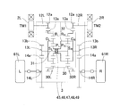
- FIG. 4 is a skeleton diagram showing the vehicle drive device.
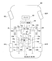
- FIG. 5 is an explanatory diagram of an electric vehicle equipped with this vehicle drive device. As shown in FIGS. 4 and 5, the left and right electric motors 2L and 2R are individually controlled by the drive source control device 67 (FIG. 1), and can generate and output different torques.
- the torques of the electric motors 2L and 2R are the teeth of the input gears 12a and 12a of the input gear shafts 12L and 12R of the power transmission device 3 and the large-diameter input side external gears 13a and 13a of the intermediate gear shafts 13L and 13R, respectively. It is increased by a number ratio and transmitted to the ring gears R L and R R of the torque difference amplifying device 30. Then, the torque difference amplifying device 30 amplifies the left and right torque difference, and the torque is transmitted from the first and second coupling members 31 and 32 to the output side small gears 13b and 13b. Further, the torque is further amplified by the gear ratio between the output-side small-diameter gears 13b and 13b and the output gears 14a and 14a, and is output to the drive wheels 61L and 61R.
- the planetary gear mechanisms 30L and 30R in the torque difference amplifying device 30 are respectively provided with coaxially provided sun gears S L and S R and ring gears R L and R R , and these sun gears S L and S R and ring gears R L and R R.
- planetary gears P L located between, P R and planetary gear P L, P R and the rotatably supported sun gear S L, S R and the ring gear R L, R R and planet carrier C L provided coaxially , and a C R.
- the sun gear S L, S R and planetary gears P L, the P R is an external gear having gear teeth on the outer periphery
- R R is an internal gear having gear teeth on the inner periphery.
- Planetary gears P L, P R is engaged the sun gear S L, S R and the ring gear R L, in the R R.
- Planetary gear mechanism 30L, the 30R respectively, the planetary carrier C L, the sun gear S L in case of fixing the C R, S R and the ring gear R L, and the R R is rotated in the reverse direction.
- the ring gear R L, R R and the sun gear S L, S R are disposed on the opposite side of the planet carrier C L, C R.
- the torque difference amplifier 30 As shown in FIGS. 4 and 5, the torque difference amplifier 30, as described above, the sun gear S L, planet carrier C L, planetary gears P L and the ring gear left planetary gear mechanism having a R L 30L, the sun gear S R, the planet carrier C R, and a right side of the planetary gear mechanism 30R having planetary gears P R and the ring gear R R is configured by combining coaxially with each other.
- a planet carrier C L which is a component of a planetary gear mechanism 30L on the left, to form a first coupling member 31 and the sun gear S R is coupled which is a component of the right planetary gear mechanism 30R.
- the sun gear S L is also a component of the left planetary gear mechanism 30L, a planet carrier C R form a second coupling member 32 is coupled which is a component of the right planetary gear mechanism 30R.
- the torque TM1 generated by the left electric motor 2L is transmitted from the input gear shaft 12L to the intermediate gear shaft 13L.
- the torque transmitted to the intermediate gear shaft 13L is amplified by the torque difference amplifying device 30 and the left and right planetary gear mechanisms 30L are sequentially used to sequentially output the output side small gear 13b and the output gear of the intermediate gear shaft 13L.
- 14a is transmitted to the output gear shaft 14L.
- a driving torque TL (FIG. 6) is output from the output gear shaft 14L to the driving wheel 61L.
- Torque TM2 generated by the right electric motor 2R is transmitted from the input gear shaft 12R to the intermediate gear shaft 13R.
- the torque transmitted to the intermediate gear shaft 13R is amplified by a torque difference amplifying device 30 and the torque difference between the left and right sides is sequentially increased via the right planetary gear mechanism 30R.
- 14a is transmitted to the output gear shaft 14R.
- a driving torque TR (FIG. 6) is output from the output gear shaft 14R to the driving wheel 61R.
- the second coupling member 32 is configured to include a hollow shaft extending along the axis of the torque difference amplifying device 30, and the first coupling member 31 is inserted into the hollow shaft.
- the first coupling member 31 includes a shaft that extends along the axis of the torque difference amplifying device 30.
- the first and second coupling members 31 and 32 are arranged coaxially, and these axes have a double structure.
- Bearings 45 and 46 are disposed between the outer peripheral surface of the first coupling member 31 and the inner peripheral surface of the second coupling member 32.
- the first and second coupling members 31 and 32 are supported with each other via bearings 45 and 46.
- the first and second coupling members 31 and 32 are rotatably supported by a thrust bearing 47 and a deep groove ball bearing 49, respectively. Further, between the first and second coupling members 31, 32, bearings 45, 46 and a thrust bearing 48 different from the bearings 47, 49 are provided.
- the driving torque transmitted by the torque difference amplifying device 30 will be described with reference to the velocity diagram shown in FIG. Since the torque difference amplifying device 30 is configured by combining two identical single pinion planetary gear mechanisms 30L and 30R, it can be represented by two velocity diagrams as shown in FIG. Here, for ease of understanding, the two speed diagrams are shifted up and down, the speed diagram of the left planetary gear mechanism 30L is shown on the upper side of FIG. 6, and the right planetary gear mechanism is shown on the lower side of FIG. A speed diagram of 30R is shown.
- the torques TM1 and TM2 output from the electric motors 2L and 2R are passed through the input side external gears 13a and 13a that mesh with the input gears 12a and 12a of the input gear shafts 12L and 12R.
- the magnitude changes depending on the reduction gear ratio because it is input to each of the ring gears R L and R R.
- the drive torques TL and TR output from the torque difference amplifying device 30 are transmitted to the left and right drive wheels 61L and 61R via the output-side small diameter gears 13b and 13b that mesh with the output gears 14a and 14a, respectively.
- the size changes according to the reduction ratio.
- the torque is changed according to these reduction ratios.
- the reduction ratio is set to 1 in the speed diagram and the explanation of each calculation formula as shown in FIG.
- the torques input to the ring gears R L and R R remain TM1 and TM2, and the drive torque remains TL and TR.
- Two single-pinion planetary gear mechanism 30L, 30R is due to the use of gear elements of the same number of teeth, in the velocity diagram, the distance between the ring gear R L and planet carrier C L and the ring gear R R and the planetary carrier the distance between the C R is equal to the distance "a". Moreover, equally the distance between the sun gear S L and the distance between the planet carrier C L and the sun gear S R and the planetary carrier C R, is the distance between "b".
- the following formula (1) is established from the balance of the moment M with respect to the point RR .
- the arrow direction M in the figure is the positive direction of the moment.
- a ⁇ TR + (a + b) ⁇ TL ⁇ (b + 2a) ⁇ TM1 0
- the torque from the electric motor 2L, 2R are respectively inputted ring gear R L, the R R, the drive wheels 61L, the torque to 61R (FIG. 5), respectively, a sun gear and planet carrier S R + C L, is outputted from the S L + C R.
- the torque difference amplifying device 30 amplifies the input torque difference ⁇ TIN, and a driving torque difference ⁇ ⁇ ⁇ TIN larger than the input torque difference ⁇ TIN can be obtained.
- the rotational angular velocities of the left and right electric motors 2L and 2R are also determined from the rotational angular velocities of the left and right drive wheels 61L and 61R and the number of gear teeth provided in the power transmission device 3.
- the number of gear teeth included in the power transmission device 3 refers to the gears of the input gear shafts 12L and 12R, the intermediate gear shafts 13L and 13R, the output gear shafts 14L and 14R, and the torque difference amplifying device 30 shown in FIG.
- the number of teeth refers to the gears of the input gear shafts 12L and 12R, the intermediate gear shafts 13L and 13R, the output gear shafts 14L and 14R, and the torque difference amplifying device 30 shown in FIG.
- the number of teeth refers to the gears of the input gear shafts 12L and 12R, the intermediate gear shafts 13L and 13R, the output gear shafts 14L and 14R, and the torque difference amplifying device 30 shown in FIG.
- TWL C1 ⁇ TM1-C2 ⁇ TM2-D1 ⁇ ⁇ WL ′ + D2 ⁇ ⁇ WR ′ (6)
- TWR ⁇ E1 ⁇ TM1 + E2 ⁇ TM2 + F1 ⁇ ⁇ WL′ ⁇ F2 ⁇ ⁇ WR ′ (7)
- C1, C2, E1, and E2 are constants determined from the number of gear teeth, and are all positive values.
- D1, D2, F1 and F2 are constants determined from the number of gear teeth and the moment of inertia of the driving wheel, gear shaft, and rotating parts such as the electric motors 2L and 2R, all of which are positive values (described later).
- Formula (8) and Formula (9). That is, the third term and the fourth term on the right side of the equations (6) and (7) represent the inertial force.
- the torque of the left and right drive wheels 61L and 61R is also acted on by the angular acceleration of the right drive wheel 61R.
- the angular acceleration of the drive wheel 61L (61R) is used, but the angular velocities of the electric motors 2L and 2R are calculated using the relational expressions of the expressions (4) and (5). It may be used.
- the drive source control device uses these braking / driving torque command values TL, TR as the following formulas (8), (9 ) Can be corrected by the torque generated by the angular acceleration of the drive wheels 61L and 61R, and the motor torque command values of the two electric motors 2L and 2R can be determined.
- FIG. 7 is a block diagram of a control system of the drive source control device 67.
- the drive source control device 67 includes torque correction means (correction means) 68, torque conversion means 69, angular velocity conversion means 70, angular acceleration calculation means 71, and inertial force calculation means 72.
- the angular velocity conversion means 70 receives angular velocities (motor angular velocities) of the two electric motors 2L and 2R (FIG. 1) from the inverter device 64, and drive wheel angular velocities corresponding to the rotational speeds of the left and right drive wheels 61L and 61R (FIG. 1). Respectively.
- the angular acceleration calculation means 71 calculates the drive wheel angular accelerations of the left and right drive wheels 61L and 61R (FIG. 1) from the drive wheel angular velocities given from the angular velocity conversion means 70.
- the inertia force calculation means 72 calculates the inertia force used for torque correction in the torque correction means 68 using the drive wheel angular accelerations of the left and right drive wheels 61L and 61R (FIG. 1).
- the inertial forces of the left and right drive wheels 61L and 61R (FIG. 1) calculated by the inertial force calculating means 72 are obtained using the above formulas (6) and (7), respectively.
- This inertial force is a value converted into torque generated in the drive wheel.
- the inertial force is calculated by the number of gear teeth, the drive wheel, the gear shaft, and the left and right electric motors 2L and 2R (see FIG. 1) A constant calculated in advance based on the moment of inertia of the rotating part is used.
- the braking / driving torque command values TL, TR of the left and right drive wheels 61L, 61R (FIG. 1) given from the command means 66a of the host ECU 66 are determined according to the inertia force given from the inertia force calculation means 72.
- the corrected braking / driving torque command value is calculated according to the equations (8) and (9).
- the corrected braking / driving torque command value is converted into a motor torque command value by the torque conversion means 69 and output to the inverter device 64.
- torque correction is performed by converting the inertial force to torque generated in the drive wheel. However, the correction is performed after the inertial force and the braking / driving torque command value are converted to values corresponding to the motor torque. Also good.
- the drive source control device 67 corrects the braking / driving torque command values of the left and right drive wheels 61L and 61R received from the host ECU 66 in consideration of the inertial force.
- the second driving wheel 61R (61L) is corrected by an inertial force so as to apply a braking force, and further the angular velocity change.
- the drive wheel 61L (61R) in which the occurrence of the correction is corrected by the inertia force so as to add the drive force.
- the second driving wheel 61R (61L) is corrected by an inertia force so as to add a driving force, and further the angular velocity.
- the drive wheel 61L (61R) in which the change has occurred is corrected by the inertia force so as to apply a braking force.
- the command value is corrected so that the influence of inertial force is eliminated.
- FIG. 8 shows a block diagram of the drive source control device 67 according to the second embodiment.
- a correction necessity determination unit (determination unit) 73 is added to the drive source control device 67 (FIG. 7) according to the second embodiment.
- the correction necessity determination unit 73 determines whether torque correction is necessary from the magnitudes of the left and right driving wheel angular accelerations, and outputs the determination result to the torque correction unit 68. Specifically, the correction necessity determination unit 73 determines that torque correction is necessary when the angular acceleration of at least one drive wheel exceeds a predetermined threshold.
- the torque correction means 68 receives the determination result that torque correction is necessary, and corrects the braking / driving torque command value based on the inertial force.
- the correction necessity determination means 73 determines that the torque correction is unnecessary when both the left and right drive wheel accelerations are equal to or less than the threshold value, and the torque correction means 68 does not correct the braking / driving torque command value.
- the torque correction means 68 does not correct the braking / driving torque command value.
- a first coupling member 31 is coupled and the sun gear S R of the right planetary gear mechanisms 30R, left and the sun gear S L of the planetary gear mechanism 30L for, although the planet carrier C R of the right planetary gear mechanism 30R form a second coupling member 32 is coupled, but is not limited to this example.
- the sun gear S L of the left side of the planetary gear mechanism 30L, a first coupling member 31 is formed is bonded and the ring gear R R of the right planetary gear mechanisms 30R, a ring gear R L on the left side of the planetary gear mechanism 30L it may have a structure in which a sun gear S R of the right planetary gear mechanism 30R form a second coupling member 32 are coupled.
- a planet carrier C L of the left side of the planetary gear mechanism 30L may have a structure in which a ring gear R R of the right planetary gear mechanism 30R form a second coupling member 32 are coupled.
- the drive source of the vehicle drive device is not limited to an electric motor, and an internal combustion engine such as a gasoline engine may be used.
- the bearings 45 and 46 between the first and second coupling members 31 and 32 may be other than needle roller bearings, and may be rolling bearings such as deep groove ball bearings and angular ball bearings, for example.
Landscapes
- Engineering & Computer Science (AREA)
- Mechanical Engineering (AREA)
- Transportation (AREA)
- General Engineering & Computer Science (AREA)
- Power Engineering (AREA)
- Chemical & Material Sciences (AREA)
- Combustion & Propulsion (AREA)
- Physics & Mathematics (AREA)
- General Physics & Mathematics (AREA)
- Automation & Control Theory (AREA)
- Life Sciences & Earth Sciences (AREA)
- Sustainable Development (AREA)
- Sustainable Energy (AREA)
- Retarders (AREA)
- Electric Propulsion And Braking For Vehicles (AREA)
Abstract
左右の駆動輪の一方または両方に角速度変化が生じた場合においても、与えられた指令値通りのトルクを出力し、車両挙動を安定化することができる駆動源制御装置を提供する。この駆動源制御装置(67)は、車両における二つの駆動源(2L,2L)を制御する駆動源制御装置(67)であって、これら二つの駆動源(2L,2L)と、左右の駆動輪(61L,61R)と、二つの駆動源(2L,2L)と左右の駆動輪(61L,61R)との間に設けられ、二つの駆動源(2L,2L)からの動力を左右の駆動輪(61L,61R)に分配し、これら左右の駆動輪(61L,61R)を駆動する動力伝達装置(3)とを備える。駆動源制御装置(67)は、駆動輪(61L,61R)の角加速度と駆動源(2L,2L)の角加速度の少なくとも一方を求める角加速度計算手段(71)と、この角加速度計算手段(71)で求められた角加速度を用いて、指令手段(66a)から与えられる、二つの駆動源(2L,2L)のそれぞれの出力についての指令値を補正するトルク補正手段(68)とを備える。
Description
本出願は、2016年10月3日出願の特願2016-195603の優先権を主張するものであり、その全体を参照により本願の一部をなすものとして引用する。
この発明は、駆動源制御装置に関し、例えば、独立した二つの駆動源から発生した駆動トルクを、左右の駆動輪にトルク差を増幅して伝達する車両駆動装置の駆動源制御装置に関する。
車両のスムーズな旋回走行の実現または、極端なアンダーステア、極端なオーバーステア等の車両の挙動変化を抑制するために、左右の駆動輪の間に大きな駆動トルクの差を発生させることが有効な場合がある。そこで、二つの駆動源と左右の駆動輪との間に、遊星歯車機構を二つ組み合わせた歯車装置を備え、トルクの差を増幅した車両駆動装置が開示されている(特許文献1,2)。
また、車両の左右輪のトルク差を発生する装置において、トルク差を発生する際にモータの慣性力だけ補正する制御装置が開示されている(特許文献3)。
特許文献1および2で示される車両駆動装置では、左右の駆動輪の一方に角速度変化が生じた場合、その角速度変化が伝わる車輪、歯車軸およびモータ等の慣性モーメントとそれらの角加速度で決まる慣性力が、歯車装置内の遊星歯車機構を介して他方の駆動輪にトルクとして伝わる。例えば、車両が旋回加速中に旋回内輪側の駆動輪が浮いて空転すると、旋回外輪側の駆動輪には前記慣性力が駆動トルクとして付加されることになり、上位ECUから指令された指令トルクとは異なるトルクを出力することになる。その結果、車両挙動が不安定になる可能性がある。
特許文献3では、左右輪の回転速度差とモータの慣性モーメントから慣性力を計算してトルクを補正しているが、特許文献1および2で示される構造を有する車両駆動装置では、左右輪の回転速度差は、二つのモータの回転速度差によって生じるため、一つのモータの慣性力だけではトルクを適切に補正することは困難である。
この発明の目的は、左右の駆動輪の一方または両方に角速度変化が生じた場合においても、与えられた指令値通りのトルクを出力し、車両挙動を安定化することができる駆動源制御装置を提供することである。
以下、便宜上理解を容易にするために、実施形態の符号を参照して説明する。
この発明の駆動源制御装置67は、車両における二つの駆動源2L,2Rを制御する駆動源制御装置67であって、前記車両が、前記二つの駆動源2L,2Rと、左右の駆動輪61L,61Rと、前記二つの駆動源2L,2Rと前記左右の駆動輪61L,61Rとの間に設けられ、前記二つの駆動源2L,2Rからの動力を前記左右の駆動輪61L,61Rに分配し、これら左右の駆動輪61L,61Rを駆動する動力伝達装置3とを備え、
当該駆動源制御装置67が、
前記左右の駆動輪61L,61Rの角加速度と前記駆動源2L,2Rの角加速度の少なくとも一方を求める角加速度計算手段71と、
この角加速度計算手段71で求められた角加速度を用いて、指令手段66aから与えられる、前記二つの駆動源2L,2Rのそれぞれの出力についての指令値を定められた条件に従って補正する補正手段68と、を備えている。
前記定められた条件は、設計等によって任意に定める条件であって、例えば、試験およびシミュレーションのいずれか一方または両方により適切な条件を求めて定められる。
当該駆動源制御装置67が、
前記左右の駆動輪61L,61Rの角加速度と前記駆動源2L,2Rの角加速度の少なくとも一方を求める角加速度計算手段71と、
この角加速度計算手段71で求められた角加速度を用いて、指令手段66aから与えられる、前記二つの駆動源2L,2Rのそれぞれの出力についての指令値を定められた条件に従って補正する補正手段68と、を備えている。
前記定められた条件は、設計等によって任意に定める条件であって、例えば、試験およびシミュレーションのいずれか一方または両方により適切な条件を求めて定められる。
この構成によると、角加速度計算手段71は、駆動輪61L,61Rまたは駆動源2L,2Rの角加速度を求める。補正手段68は、求められた角加速度を用いて、指令手段66aから与えられた二つの駆動源2L,2Rのそれぞれの出力についての指令値を定められた条件に従って補正する。例えば、左右の駆動輪61L,61Rのうちいずれか一方の駆動輪61L(61R)に角加速度が生じたときに、この角加速度と逆方向となるトルクを、前記左右の駆動輪61L,61Rのうち他方の駆動輪61R(61L)に付加するように、前記二つの駆動源2L,2Rのそれぞれの出力についての指令値を補正する。したがって、車両の左右の駆動輪61L,61Rの一方または両方に不所望な角速度変化が生じた場合においても、指令手段66aから与えられた指令値通りのトルクを出力することができる。これにより車両挙動を安定化することができる。
前記補正手段68は、前記角加速度計算手段71で求められた角加速度を用い、かつ所定の回転部の慣性モーメントおよび前記動力伝達装置3の歯車の歯数に従って、前記二つの駆動源2L,2Rのそれぞれの出力についての指令値を補正してもよい。前記所定の回転部は、設計等によって任意に定める回転部(回転部品または回転部位)であって、例えば、試験およびシミュレーションのいずれか一方または両方により適切な回転部を求めて定められる。この構成によると、補正手段68は、慣性力の影響が無くなるように、二つの駆動源2L,2Rのそれぞれの出力についての指令値を補正することができる。
前記動力伝達装置3はトルク差増幅装置30を備えてもよい。このトルク差増幅装置30は、二つの遊星歯車機構30L,30Rを有し、前記二つの駆動源2L,2Rが発生するトルクの差を増幅する。この場合、二つの駆動源2L,2Rが発生するトルクの差をトルク差増幅装置30で増幅することで、車両のスムーズな旋回走行を実現することができる。このようなトルク差増幅装置30を備えた車両においても、指令手段66aから与えられた指令値通りのトルクを出力することができる。
前記補正手段68は、前記左右の駆動輪61L,61Rのうち少なくともいずれか一方の駆動輪61L(61R)の角加速度を用いて、前記二つの駆動源2L,2Rのそれぞれの出力についての前記指令値を補正してもよい。前記補正手段68は、前記二つの駆動源2L,2Rの角加速度を用いて、前記二つの駆動源2L,2Rのそれぞれの出力についての前記指令値を補正してもよい。
前記補正手段68は、前記左右の駆動輪61L,61Rのうちいずれか一方の駆動輪61L(61R)に角加速度が生じたときに、この角加速度と逆方向となるトルクを、前記前記左右の駆動輪のうち他方の駆動輪61R(61L)に付加するように、前記二つの駆動源2L,2Rのそれぞれの出力についての前記指令値を補正してもよい。このように他方の駆動輪61R(61L)には、一方の駆動輪61L(61R)の角加速度と逆方向となるトルクを付加するように慣性力に基づいた補正を行うことができる。
前記補正手段68は、前記左右の駆動輪61L,61Rのうちいずれか一方の駆動輪61L(61R)に角加速度が生じたときに、この角加速度と同じ方向となるトルクを、前記一方の駆動輪61L(61R)に付加するように、前記二つの駆動源2L,2Rのそれぞれの出力についての前記指令値を補正してもよい。このように角加速度が生じた駆動輪61L(61R)には、この角加速度と同じ方向となるトルクを付加するように慣性力に基づいた補正を行うことができる。
前記角加速度計算手段71で求められた前記角加速度が閾値を超えるか否かを判定する判定手段73を備え、前記角加速度が閾値を超えると前記判定手段73が判定したときのみ、前記補正手段68は前記二つの駆動源2L,2Rのそれぞれの出力についての前記指令値を補正してもよい。前記閾値は、設計等によって任意に定める閾値であって、例えば、試験およびシミュレーションのいずれか一方または両方により適切な閾値を求めて定められる。この構成によると、駆動輪61L,61Rの角加速度が閾値以下つまり小さいとき、指令値の補正は行わないことで、駆動源制御装置67での計算負荷を抑制できると共に、トルクを常時補正することに起因する不要なトルク変動を抑えることができる。
この発明の車両は、前記車両であって、前記駆動源制御装置67を備えている。この場合、車両の左右の駆動輪61L,61Rの一方または両方に不所望な角速度変化が生じた場合においても、指令手段66aから与えられた指令値通りのトルクを出力することができる。これにより車両挙動を安定化することができる。
請求の範囲および/または明細書および/または図面に開示された少なくとも2つの構成のどのような組合せも、本発明に含まれる。特に、請求の範囲の各請求項の2つ以上のどのような組合せも、本発明に含まれる。
この発明は、添付の図面を参考にした以下の好適な実施形態の説明から、より明瞭に理解されるであろう。しかしながら、実施形態および図面は単なる図示および説明のためのものであり、この発明の範囲を定めるために利用されるべきものではない。この発明の範囲は添付の請求の範囲によって定まる。添付図面において、複数の図面における同一の符号は、同一または相当する部分を示す。
この発明の第1の実施形態に係る駆動源制御装置と、車両駆動装置とを備えた車両の概念構成を示すブロック図である。
図1の車両駆動装置の断面図である。
図1の車両駆動装置のトルク差増幅装置部分を拡大して示す断面図である。
図1の車両駆動装置を示すスケルトン図である。
図1の車両駆動装置を搭載した電気自動車の説明図である。
図1の車両駆動装置によるトルク差増幅率を説明するための速度線図である。
図1の駆動源制御装置の制御系のブロック図である。
この発明の第2の実施形態に係る駆動源制御装置の制御系のブロック図である。
この発明の第1の実施形態に係る駆動源制御装置およびこの駆動源制御装置を備えた車両を図1ないし図7と共に説明する。図1は、この駆動源制御装置および車両駆動装置を備えた車両(電気自動車)の概念構成を示すブロック図である。この車両は、後輪駆動方式であり、シャーシ60、後輪である駆動輪61L,61R、前輪62L,62R、車両駆動装置1、上位ECU66、駆動源制御装置67、バッテリ63およびインバータ装置64等を備える。
車両駆動装置1は、第1,第2電動モータ2L,2Rと、動力伝達装置3を備えている。第1,第2電動モータ2L,2Rは、車両に搭載され独立して制御可能な二つの駆動源である。動力伝達装置は、これら第1,第2電動モータ2L,2Rと駆動輪61L,61Rとの間に設けられる。なお、本開示における「第1」および「第2」の語は、順序を示すものではなく、単に区別のために用いられる。また、「左側」および「右側」の語についても、優劣をつけるものではなく、単に区別のために用いられる。
<制御系の概略構成について>
上位ECU66は、駆動源制御装置67の上位の制御手段であり、例えば、車両全般の統括制御および協調制御を行う機能と、左右の駆動輪61L,61Rの制駆動トルク指令値を生成する機能とを有する。上位ECU66は、図示外のアクセル操作部が出力する加速指令と、図示外のブレーキ操作部が出力する減速指令と、図示外の操舵角センサ等が出力する旋回指令とから、左右の制駆動トルク指令値(出力についての指令値)を生成する。
上位ECU66は、駆動源制御装置67の上位の制御手段であり、例えば、車両全般の統括制御および協調制御を行う機能と、左右の駆動輪61L,61Rの制駆動トルク指令値を生成する機能とを有する。上位ECU66は、図示外のアクセル操作部が出力する加速指令と、図示外のブレーキ操作部が出力する減速指令と、図示外の操舵角センサ等が出力する旋回指令とから、左右の制駆動トルク指令値(出力についての指令値)を生成する。
駆動源制御装置67は、上位ECU66から与えられた左右の制駆動トルク指令値に基づいて、インバータ装置64にモータトルク指令値を与える。これにより第1,第2電動モータ2L,2Rは個別に制御される。インバータ装置64は、バッテリ63の直流電力を第1,第2電動モータ2L,2Rの駆動のための交流電力に変換する。インバータ装置64は、第1,第2電動モータ2L,2Rが出力するトルクがモータトルク指令値と等しくなるように、バッテリ63から供給される電流を制御し第1,第2電動モータ2L,2Rを駆動する。車両駆動装置1からの出力は等速ジョイントを介して左右の駆動輪61L,61Rに伝達される。
<車両駆動装置1について>
<<第1,第2電動モータ2L,2Rについて>>
この実施形態では、車両駆動装置1における第1,第2電動モータ2L,2Rは、同一の最大出力を有する同一規格の電動モータを用いている。図2に示すように、第1,第2電動モータ2L,2Rは、モータハウジング4L,4Rと、ステータ6,6と、ロータ5,5とを有する。第1,第2電動モータ2L,2Rは、それぞれ、モータハウジング4L,4Rの内周面にステータ6,6が設けられ、各ステータ6の内周に間隔を隔ててロータ5を設けたラジアルギャップタイプである。
<<第1,第2電動モータ2L,2Rについて>>
この実施形態では、車両駆動装置1における第1,第2電動モータ2L,2Rは、同一の最大出力を有する同一規格の電動モータを用いている。図2に示すように、第1,第2電動モータ2L,2Rは、モータハウジング4L,4Rと、ステータ6,6と、ロータ5,5とを有する。第1,第2電動モータ2L,2Rは、それぞれ、モータハウジング4L,4Rの内周面にステータ6,6が設けられ、各ステータ6の内周に間隔を隔ててロータ5を設けたラジアルギャップタイプである。
モータハウジング4L,4Rは、それぞれ、円筒形のモータハウジング本体4aL,4aRと、外側壁4bL,4bRと、内側壁4cL,4cRとを有する。外側壁4bL,4bRは、モータハウジング本体4aL,4aRにおけるアウトボード側の外側面を閉塞する。内側壁4cL,4cRは、モータハウジング本体4aL,4aRにおけるインボード側の内側面に設けられ、動力伝達装置3と隔てる隔壁を成す。内側壁4cL,4cRには、各モータ軸5aをインボード側に引き出す開口部が設けられている。なおこの明細書において、車両駆動装置1が車両に搭載された状態で車両の車幅方向の外側寄りとなる側をアウトボード側と呼び、車両の車幅方向の中央寄りとなる側をインボード側と呼ぶ。
モータハウジング本体4aL,4aRの内周面に、ステータ6,6がそれぞれ嵌合固定されている。各ロータ5は、モータ軸5aを中心部に有する。内側壁4cL,4cRそれぞれには転がり軸受8aが設けられ、外側壁4bL,4bRそれぞれにも、転がり軸受8bが設けられている。各モータ軸5aは、モータハウジング4L,4Rに転がり軸受8a,8bを介して回転自在に支持されている。左右のモータ軸5a,5aは同一軸心上(同軸)に設けられている。
<<動力伝達装置3について>>
動力伝達装置3は、動力伝達装置ハウジング9を有する。動力伝達装置3はさらに、左右二つの入力歯車軸12L,12Rと、左右二つの中間歯車軸13L,13Rと、左右二つの出力歯車軸14L,14Rと、トルク差増幅装置30とを有する。動力伝達装置3は、第1,第2電動モータ2L,2Rのモータ軸5aから入力されたトルク(駆動トルク)の差をトルク差増幅装置30で増幅し、駆動輪61L,61R(図1)へと伝達する装置である。
動力伝達装置3は、動力伝達装置ハウジング9を有する。動力伝達装置3はさらに、左右二つの入力歯車軸12L,12Rと、左右二つの中間歯車軸13L,13Rと、左右二つの出力歯車軸14L,14Rと、トルク差増幅装置30とを有する。動力伝達装置3は、第1,第2電動モータ2L,2Rのモータ軸5aから入力されたトルク(駆動トルク)の差をトルク差増幅装置30で増幅し、駆動輪61L,61R(図1)へと伝達する装置である。
動力伝達装置ハウジング9は、これらの歯車軸およびトルク差増幅装置30を収容する。動力伝達装置ハウジング9は、前記歯車軸の軸方向に直交する方向に三ピースに分割された三ピース構造である。具体的に、動力伝達装置ハウジング9は、中央ハウジング9aと、この中央ハウジング9aの両側面に固定される左右の側面ハウジング9bL,9bRとを有する。
側面ハウジング9bL,9bRのアウトボード側の側面と、内側壁4cL,4cRとが、複数のボルトで固定される。これにより、動力伝達装置ハウジング9の左右両端に二基の電動モータ2L,2Rが固定される。中央ハウジング9aには、中央に仕切り壁11が設けられている。動力伝達装置ハウジング9は、仕切り壁11によって左右に二分割され、これらが動力伝達装置3の本体部を収容する。この動力伝達装置3の本体部は、左右対称形であり、前記入力歯車軸12L,12Rと、中間歯車軸13L,13Rと、出力歯車軸14L,14Rと、トルク差増幅装置30とを備えている。
入力歯車軸12L,12Rは、モータ軸5aから動力が伝達される入力歯車12aを有する。仕切り壁11に形成された軸受嵌合穴に転がり軸受17aが設けられ、左右の側面ハウジング9bL,9bRに形成された軸受嵌合穴に転がり軸受17bが設けられている。入力歯車軸12L,12Rの両端は、いずれも、動力伝達装置ハウジング9に転がり軸受17a,17bを介して回転自在に支持されている。入力歯車軸12L,12Rは中空構造である。この入力歯車軸12L,12Rの中空内部に、各モータ軸5aのインボード側の端部が挿入されている。入力歯車軸12L,12Rと各モータ軸5aとは、スプライン(「セレーション」も含む。以下のスプラインについても同様に「セレーション」を含む。)結合されている。
図3に示すように、左右の中間歯車軸13L,13Rは、同軸に配置されている。中間歯車軸13L,13Rは、入力歯車12a,12aに噛み合う大径の入力側外歯車13a,13aと、後述する出力歯車14a,14aに噛み合う出力側小径歯車13b,13bとを有する。仕切り壁11に形成された軸受嵌合穴19aに転がり軸受20aが設けられ、左右の側面ハウジング9bL,9bRに形成された軸受嵌合穴19bに転がり軸受20bが設けられている。中間歯車軸13L,13Rの各両端は、動力伝達装置ハウジング9に転がり軸受20a,20bを介して回転自在に支持されている。軸受嵌合穴19a,19bは、それぞれ、転がり軸受20a,20bの外輪端面が当接する段付き形状であり、後述する第1,第2の結合部材31,32が通るように貫通している。
中間歯車軸13L,13Rには、この中間歯車軸13L,13Rと同軸にトルク差増幅装置30が組み込まれている。トルク差増幅装置30は、二つの電動モータ2L,2R(図2)から与えられるトルク(駆動トルク)の差を増幅する。このトルク差増幅装置30は、3要素2自由度の二つの遊星歯車機構30L,30Rを備える。遊星歯車機構30L,30Rには、この例では、シングルピニオン遊星歯車機構が採用されている。二つの遊星歯車機構30L,30Rは同軸に設けられている。
遊星歯車機構30L,30Rは、それぞれ、リングギヤRL,RRと、サンギヤSL,SRと、プラネタリギヤPL,PRと、遊星キャリアCL,CRとを有する。これら遊星歯車機構30L,30Rは、また、共通の第1,第2の結合部材31,32を有する。リングギヤRL,RRは、中間歯車軸13L,13Rの入力側外歯車13a,13aにそれぞれ組み込まれた内歯車である。サンギヤSL,SRは、リングギヤRL,RRと同軸に設けられた太陽歯車である。プラネタリギヤPL,PRは、リングギヤRL,RRとサンギヤSL,SRに噛み合う公転歯車である。遊星キャリアCL,CRは、それぞれ、プラネタリギヤPL,PRに連結され、リングギヤRL,RRと同軸に設けられている。遊星キャリアCL,CRには、それぞれ、中間歯車軸13L,13Rの出力側小径歯車13b,13bが連結されている。
第1の結合部材31は、図3の紙面左側の遊星歯車機構30Lの構成部材である左側の遊星キャリアCLと、図3の紙面右側の遊星歯車機構30Rの構成部材である右側のサンギヤSRとを結合する。第2の結合部材32は、図3の紙面左側の遊星歯車機構30Lの構成部材である左側のサンギヤSLと、図3の紙面右側の遊星歯車機構30Rの構成部材である右側の遊星キャリアCRとを結合する。
遊星キャリアCL,CRは、それぞれ、プラネタリギヤPL,PRを支持するキャリアピン33,33と、アウトボード側のキャリアフランジ34a,34aと、インボード側のキャリアフランジ34b,34bとを有する。プラネタリギヤPL,PRは、それぞれ、針状ころ軸受37,37を介してキャリアピン33,33に支持されている。アウトボード側のキャリアフランジ34a,34aは、それぞれ、キャリアピン33,33のアウトボード側端部に連結されている。インボード側のキャリアフランジ34b,34bは、それぞれ、キャリアピン33,33のインボード側端部に連結されている。
アウトボード側のキャリアフランジ34a,34aは、それぞれ、アウトボード側に延びる中空軸部35,35を備える。この中空軸部35,35のアウトボード側の端部が、それぞれ、側面ハウジング9bL,9bRにそれぞれ形成された軸受嵌合穴19b,19bに転がり軸受20b,20bを介して支持されている。インボード側のキャリアフランジ34b,34bは、それぞれ、インボード側に延びる中空軸部36,36を備える。これら中空軸部36,36のインボード側の端部が、それぞれ、仕切り壁11に形成された軸受嵌合穴19a,19aに転がり軸受20a,20aを介して支持されている。紙面左側の遊星歯車機構30Lのキャリアフランジ34a,34bの外周面とリングギヤRLの間、および、紙面右側の遊星歯車機構30Rのキャリアフランジ34a,34bの外周面とリングギヤRRの間には、いずれも、転がり軸受39a,39bが設けられている。
二つの遊星歯車機構30L,30Rを互いに連結している第1,第2の結合部材31,32は、中央ハウジング9a(図2)を左右に仕切る仕切り壁11を貫通して組み込まれている。第1,第2の結合部材31,32は、互いに同軸に位置して、それぞれスラスト軸受47によりアキシアル方向に回転自在に支持され、かつ深溝玉軸受49によりラジアル方向に回転自在に支持される。さらに第1,第2の結合部材31,32間には、軸受47,49とは別の軸受45,46,スラスト軸受48が設けられている。別の軸受45,46は、それぞれ針状ころ軸受である。第2の結合部材32が中空軸を有し、第1の結合部材31が前記中空軸に挿通される軸を有する。
第2の結合部材32における図3の紙面右側のアウトボード側の外周面と、遊星キャリアCRにおけるインボード側のキャリアフランジ34bの中空軸部36とに互いに噛み合うスプラインが設けられている。よって、第2の結合部材32は、遊星キャリアCRに対しスプライン嵌合により連結されている。したがって、第2の回転部材である遊星キャリアCRは、第2の結合部材32と一体となって回転する。
第1の結合部材31における図3の紙面左側のアウトボード側の外周面と、遊星キャリアCLにおけるアウトボード側のキャリアフランジ34aの中空軸部35とに互いに噛み合うスプラインが設けられている。よって、第1の結合部材31は、遊星キャリアCLに対しスプライン嵌合により連結されている。したがって、第1の回転部材である遊星キャリアCLは、第1の結合部材31と一体となって回転する。
前述のように、第1,第2の結合部材31,32が、それぞれ、遊星キャリアCL,CRに対しスプライン嵌合により連結されているため、二つの遊星歯車機構30L,30Rは左右に分割可能となり、三ピース構造の動力伝達装置ハウジング9に他の減速歯車軸と共に左右から組み込み可能である。第2の結合部材32における遊星キャリアCL側の端部は、その外周面に、図3の紙面左側の遊星歯車機構30LのサンギヤSLを構成する外歯車が形成されている。このサンギヤSLを構成する外歯車がプラネタリギヤPLと噛み合う。
第1の結合部材31は、図3の紙面右側の遊星歯車機構30R側の端部に大径部43を有する。この大径部43の外周面に、図3の紙面右側の遊星歯車機構30RのサンギヤSRを構成する外歯車が形成されている。このサンギヤSRを構成する外歯車がプラネタリギヤPRと噛み合う。第2の結合部材32の軸方向両端には、スラスト軸受47,48がそれぞれ設けられている。これらスラスト軸受47,48により、それぞれ、第1,第2の結合部材31,32と遊星キャリアCL,CRとのスプライン嵌合部の摺動による軸方向移動が規制される。第1の結合部材31は、図3の紙面右側の端部が、遊星キャリアCRに対して深溝玉軸受49によって支持されている。第1の結合部材31の軸心には、給油穴が設けられている。
図2に示すように、出力歯車軸14L,14Rは、それぞれ、大径の出力歯車14a,14aを有する。仕切り壁11に形成された軸受嵌合穴19a,19aに転がり軸受54a,54aが設けられ、左右の側面ハウジング9bL,9bRにそれぞれ形成された軸受嵌合穴19b,19bに転がり軸受54b,54bが設けられている。出力歯車軸14L,14Rは、いずれも、動力伝達装置ハウジング9に転がり軸受54a,54bを介して回転自在に支持されている。
出力歯車軸14L,14Rのアウトボード側の端部は、それぞれ、側面ハウジング9bL,9bRに形成された開口部から動力伝達装置ハウジング9の外側に引き出されている。引き出された出力歯車軸14L,14Rのアウトボード側の端部の外周面に、等速ジョイント65aの外側継手部がスプライン結合されている。各等速ジョイント65aは、図示外の中間シャフト等を介して駆動輪61L,61R(図1)に接続されている。
図4は、この車両駆動装置を示すスケルトン図である。図5は、この車両駆動装置を搭載した電気自動車の説明図である。図4および図5に示すように、左右の電動モータ2L,2Rは、駆動源制御装置67(図1)により個別に制御され、異なるトルクを発生させて出力し得る。
電動モータ2L,2Rのトルクは、それぞれ、動力伝達装置3の入力歯車軸12L,12Rの入力歯車12a,12aと、中間歯車軸13L,13Rの大径の入力側外歯車13a,13aとの歯数比で増大されて、トルク差増幅装置30のリングギヤRL,RRに伝達される。そして、トルク差増幅装置30により左右のトルク差が増幅され、第1,第2の結合部材31,32から出力側小径歯車13b,13bへとトルクが伝達される。そして、さらに出力側小径歯車13b,13bと出力歯車14a,14aとの歯数比でトルクがそれぞれさらに増幅されて、駆動輪61L,61Rに出力される。
トルク差増幅装置30における遊星歯車機構30L,30Rは、それぞれ、同軸に設けられたサンギヤSL,SRおよびリングギヤRL,RRと、これらサンギヤSL,SRとリングギヤRL,RRとの間に位置するプラネタリギヤPL,PRと、プラネタリギヤPL,PRを回動可能に支持しサンギヤSL,SRおよびリングギヤRL,RRと同軸に設けられた遊星キャリアCL,CRとを有する。ここで、サンギヤSL,SRとプラネタリギヤPL,PRは外周にギヤ歯を有する外歯歯車であり、リングギヤRL,RRは内周にギヤ歯を有する内歯歯車である。プラネタリギヤPL,PRはサンギヤSL,SRとリングギヤRL,RRとに噛み合っている。
遊星歯車機構30L,30Rでは、それぞれ、遊星キャリアCL,CRを固定した場合にサンギヤSL,SRとリングギヤRL,RRとが逆方向に回転する。このため、図6に示す速度線図に表すと、リングギヤRL,RRおよびサンギヤSL,SRが遊星キャリアCL,CRに対して反対側に配置される。
図4および図5に示すように、このトルク差増幅装置30は、前述のように、サンギヤSL、遊星キャリアCL、プラネタリギヤPLおよびリングギヤRLを有する左側の遊星歯車機構30Lと、サンギヤSR、遊星キャリアCR、プラネタリギヤPRおよびリングギヤRRを有する右側の遊星歯車機構30Rとが互いに同軸に組み合わされて構成されている。
左側の遊星歯車機構30Lの構成部材である遊星キャリアCLと、右側の遊星歯車機構30Rの構成部材であるサンギヤSRとが結合されて第1の結合部材31を形成している。また左側遊星歯車機構30Lの構成部材であるサンギヤSLと、右側の遊星歯車機構30Rの構成部材である遊星キャリアCRとが結合されて第2の結合部材32を形成している。
左側の電動モータ2Lで発生したトルクTM1は、入力歯車軸12Lから中間歯車軸13Lに伝達される。この中間歯車軸13Lに伝達されたトルクは、トルク差増幅装置30により左右のトルク差が増幅され、左側の遊星歯車機構30Lを介して順次、中間歯車軸13Lの出力側小径歯車13b、出力歯車14a、出力歯車軸14Lに伝達される。出力歯車軸14Lから駆動輪61Lに駆動トルクTL(図6)が出力される。右側の電動モータ2Rで発生したトルクTM2は、入力歯車軸12Rから中間歯車軸13Rに伝達される。この中間歯車軸13Rに伝達されたトルクは、トルク差増幅装置30により左右のトルク差が増幅され、右側の遊星歯車機構30Rを介して順次、中間歯車軸13Rの出力側小径歯車13b、出力歯車14a、出力歯車軸14Rに伝達される。出力歯車軸14Rから駆動輪61Rに駆動トルクTR(図6)が出力される。
第2の結合部材32は、トルク差増幅装置30の軸心に沿って延在する中空軸を含んで構成され、その中空軸の内部には、第1の結合部材31が挿通されている。第1の結合部材31は、トルク差増幅装置30の軸心に沿って延在する軸を含んで構成されている。第1,第2の結合部材31,32は、同軸上に配置されて、これらの軸は二重構造となっている。第1の結合部材31の外周面と第2の結合部材32の内周面の間には、軸受45,46が配置されている。第1,第2の結合部材31,32は、軸受45,46を介して相互に支持されている。第1,第2の結合部材31,32は、それぞれスラスト軸受47、深溝玉軸受49により回転自在に支持される。さらに第1,第2の結合部材31,32間には、軸受47,49とは別の軸受45,46,スラスト軸受48が設けられている。
<駆動トルク等について>
ここで、トルク差増幅装置30によって伝達される駆動トルクについて、図6に示す速度線図を用いて説明する。トルク差増幅装置30は、二つの同一のシングルピニオン遊星歯車機構30L,30Rを組み合わせて構成されるため、同図6に示すように二本の速度線図によって表すことができる。ここでは、分かりやすいように、二本の速度線図を上下にずらし、図6の紙面上側に左側の遊星歯車機構30Lの速度線図を示し、図6の紙面下側に右側の遊星歯車機構30Rの速度線図を示す。
ここで、トルク差増幅装置30によって伝達される駆動トルクについて、図6に示す速度線図を用いて説明する。トルク差増幅装置30は、二つの同一のシングルピニオン遊星歯車機構30L,30Rを組み合わせて構成されるため、同図6に示すように二本の速度線図によって表すことができる。ここでは、分かりやすいように、二本の速度線図を上下にずらし、図6の紙面上側に左側の遊星歯車機構30Lの速度線図を示し、図6の紙面下側に右側の遊星歯車機構30Rの速度線図を示す。
本来は、図5に示すように、各電動モータ2L,2Rから出力されたトルクTM1およびTM2は、各入力歯車軸12L,12Rの入力歯車12a,12aと噛み合う入力側外歯車13a,13aを介して、各リングギヤRL,RRに入力されるため、減速比に応じて大きさが変わる。また、トルク差増幅装置30から出力された駆動トルクTL,TRは、それぞれ、出力歯車14a,14aと噛み合う出力側小径歯車13b,13bを介して、左右の駆動輪61L,61Rへ伝達されるため、減速比に応じて大きさが変わる。
この車両駆動装置ではこれらの減速比に応じてトルクが変更されるが、以降、理解を容易にするため、図6に示すように、速度線図および各計算式の説明においては減速比を1とし、各リングギヤRL,RRに入力されるトルクをTM1,TM2のままとし、駆動トルクはTL,TRのままとする。
二つのシングルピニオン遊星歯車機構30L,30Rは、同一の歯数の歯車要素を使用しているため、速度線図においては、リングギヤRLと遊星キャリアCLとの距離およびリングギヤRRと遊星キャリアCRとの距離は等しく、この距離を「a」とする。また、サンギヤSLと遊星キャリアCLとの距離およびサンギヤSRと遊星キャリアCRとの距離も等しく、この距離を「b」とする。
遊星キャリアCL,CRそれぞれからリングギヤRL,RRまでの長さと遊星キャリアCL,CRそれぞれからサンギヤSL,SRまでの長さの比は、リングギヤRL,RRの歯数Zrの逆数(1/Zr)とサンギヤSL,SRの歯数Zsの逆数(1/Zs)との比と等しい。よって、a=(1/Zr)、b=(1/Zs)である。
RRの点を基準にしたモーメントMの釣り合いから下記式(1)が成立する。なお図6において、図中矢印方向Mがモーメントの正方向である。
a・TR+(a+b)・TL-(b+2a)・TM1=0 …(1)
RLの点を基準にしたモーメントMの釣り合いから下記式(2)が成立する。
-a・TL-(a+b)・TR+(b+2a)・TM2=0 …(2)
a・TR+(a+b)・TL-(b+2a)・TM1=0 …(1)
RLの点を基準にしたモーメントMの釣り合いから下記式(2)が成立する。
-a・TL-(a+b)・TR+(b+2a)・TM2=0 …(2)
(1)式+(2)式より、下記式(3)が得られる。
-b・(TR-TL)+(2a+b)・(TM2-TM1)=0
(TR-TL)=((2a+b)/b)・(TM2-TM1) …(3)
式(3)の(2a+b)/bがトルク差増幅率αとなる。a=1/Zr、b=1/Zsを代入すると、α=(Zr+2Zs)/Zrとなり、下記のトルク差増幅率αが得られる。
α=(Zr+2Zs)/Zr
-b・(TR-TL)+(2a+b)・(TM2-TM1)=0
(TR-TL)=((2a+b)/b)・(TM2-TM1) …(3)
式(3)の(2a+b)/bがトルク差増幅率αとなる。a=1/Zr、b=1/Zsを代入すると、α=(Zr+2Zs)/Zrとなり、下記のトルク差増幅率αが得られる。
α=(Zr+2Zs)/Zr
この例では、電動モータ2L,2R(図5)からのトルクは、それぞれ、リングギヤRL,RRに入力され、駆動輪61L,61R(図5)へのトルクは、それぞれ、サンギヤと遊星キャリアSR+CL,SL+CRから出力される。
図5および図6に示すように、第1の結合部材31と第2の結合部材32の回転速度の差が小さい場合、二つの電動モータ2L,2Rで異なるトルクTM1,TM2を発生させて入力トルク差ΔTIN(=(TM1-TM2))を与えると、トルク差増幅装置30において入力トルク差ΔTINが増幅され、入力トルク差ΔTINよりも大きな駆動トルク差α・ΔTINを得ることができる。
すなわち、入力トルク差ΔTINが小さくても、トルク差増幅装置30において前記トルク差増幅率α(=(Zr+2Zs)/Zr)で入力トルク差ΔTINを増幅することができる。よって、左駆動輪61Lと右駆動輪61Rとに伝達される駆動トルクTL,TRに、入力トルク差ΔTINよりも大きな駆動トルク差ΔTOUT(=α・(TM2-TM1))を与えることができる。
図1に示すように、左右の電動モータ2L,2Rの回転角速度も、左右の駆動輪61L,61Rの回転角速度および動力伝達装置3が備える歯車の歯数から決まる。なお、動力伝達装置3が備える歯車の歯数とは、図2の入力歯車軸12L,12R、中間歯車軸13L,13R、出力歯車軸14L,14R、および、トルク差増幅装置30が有する歯車の歯数である。以下では、「動力伝達装置3が備える歯車の歯数」を単に、「歯車の歯数」と称する。
ここで、左右の電動モータ2L,2Rの回転速度をそれぞれωM1,ωM2とし、左右の駆動輪61L,61Rの回転速度をそれぞれωWL,ωWRとすると、以下の関係式が成り立つ。
ωM1=A1×ωWL-A2×ωWR …(4)
ωM2=-B1×ωWL+B2×ωWR …(5)
但し、A1,A2,B1およびB2は、歯車の歯数から決まる定数であり、全て正の値である。左右の駆動輪61L,61Rの一方が回転すると、二つの電動モータ2L,2Rの両方が回転する。言い換えれば、一方の駆動輪61L(61R)を回転させるためには二つの電動モータ2L,2Rの両方を回転させることになる。
ωM1=A1×ωWL-A2×ωWR …(4)
ωM2=-B1×ωWL+B2×ωWR …(5)
但し、A1,A2,B1およびB2は、歯車の歯数から決まる定数であり、全て正の値である。左右の駆動輪61L,61Rの一方が回転すると、二つの電動モータ2L,2Rの両方が回転する。言い換えれば、一方の駆動輪61L(61R)を回転させるためには二つの電動モータ2L,2Rの両方を回転させることになる。
<車両駆動装置のトルクの関係式について>
左右の電動モータ2L,2RのトルクをTM1,TM2とし、左右の駆動輪61L,61RのトルクをTWL,TWRとし、左右の駆動輪61L,61Rの角加速度をωWL´,ωWR´とすると、以下の関係式が成り立つ。
左右の電動モータ2L,2RのトルクをTM1,TM2とし、左右の駆動輪61L,61RのトルクをTWL,TWRとし、左右の駆動輪61L,61Rの角加速度をωWL´,ωWR´とすると、以下の関係式が成り立つ。
TWL=C1×TM1-C2×TM2-D1×ωWL´+D2×ωWR´ …(6)
TWR=-E1×TM1+E2×TM2+F1×ωWL´-F2×ωWR´ …(7)
但し、C1,C2,E1およびE2は歯車の歯数から決まる定数であり、全て正の値である。またD1,D2,F1およびF2は、歯車の歯数と、駆動輪、歯車軸、および電動モータ2L,2R等の回転部の慣性モーメントから決まる定数であり、全て正の値である(後述する式(8)および式(9)についても同じである。)。すなわち、式(6)および式(7)の右辺の第3項および第4項は慣性力を表している。
TWR=-E1×TM1+E2×TM2+F1×ωWL´-F2×ωWR´ …(7)
但し、C1,C2,E1およびE2は歯車の歯数から決まる定数であり、全て正の値である。またD1,D2,F1およびF2は、歯車の歯数と、駆動輪、歯車軸、および電動モータ2L,2R等の回転部の慣性モーメントから決まる定数であり、全て正の値である(後述する式(8)および式(9)についても同じである。)。すなわち、式(6)および式(7)の右辺の第3項および第4項は慣性力を表している。
ここで、車両の左の駆動輪61Lに進行方向に対して加速方向の角加速度が生じる場合を考える(ωWL´>0)。式(6)から、左の駆動輪61Lの加速方向の角加速度によって、左の駆動輪61Lに減速方向のトルクが作用する。また式(7)から、左の駆動輪61Lの加速方向の角加速度によって、右の駆動輪61Rに加速方向のトルクが作用する。
左の駆動輪61Lに減速方向の角加速度が生じた場合には、上記とは逆向きのトルクが作用する。つまり左の駆動輪61Lの減速方向の角加速度によって、左の駆動輪61Lに加速方向のトルクが作用する。また左の駆動輪61Lの減速方向の角加速度によって、右の駆動輪61Rに減速方向のトルクが作用する。
これら左右の駆動輪61L,61Rのトルクは、右の駆動輪61Rの角加速度によっても作用される。式(6)と式(7)では、駆動輪61L(61R)の角加速度を用いているが、式(4)と式(5)の関係式を用いて、電動モータ2L,2Rの角速度を用いてもよい。
上位ECU66からの左右の駆動輪61L,61Rの制駆動トルク指令値をTL,TRとした場合、駆動源制御装置は、これら制駆動トルク指令値TL,TRを、次式(8),(9)により駆動輪61L,61Rの角加速度によって生じる上記トルク分だけ補正し、二つの電動モータ2L,2Rのモータトルク指令値を決定することができる。
TL+D1×ωWL´-D2×ωWR´=C1×TM1-C2×TM2 …(8)
TR-F1×ωWL´+F2×ωWR´=-E1×TM1+E2×TM2 …(9)
TL+D1×ωWL´-D2×ωWR´=C1×TM1-C2×TM2 …(8)
TR-F1×ωWL´+F2×ωWR´=-E1×TM1+E2×TM2 …(9)
図7は、この駆動源制御装置67の制御系のブロック図である。
駆動源制御装置67は、トルク補正手段(補正手段)68、トルク変換手段69、角速度変換手段70、角加速度計算手段71および慣性力計算手段72を備えている。角速度変換手段70では、インバータ装置64から二つの電動モータ2L,2R(図1)の角速度(モータ角速度)を受け取り、左右の駆動輪61L,61R(図1)の回転速度に相当する駆動輪角速度にそれぞれ変換している。角加速度計算手段71は、角速度変換手段70から与えられた駆動輪角速度それぞれから、左右の駆動輪61L,61R(図1)の駆動輪角加速度を計算する。慣性力計算手段72は、トルク補正手段68においてトルクの補正に用いる慣性力を、左右の駆動輪61L,61R(図1)の駆動輪角加速度を用いて計算する。
駆動源制御装置67は、トルク補正手段(補正手段)68、トルク変換手段69、角速度変換手段70、角加速度計算手段71および慣性力計算手段72を備えている。角速度変換手段70では、インバータ装置64から二つの電動モータ2L,2R(図1)の角速度(モータ角速度)を受け取り、左右の駆動輪61L,61R(図1)の回転速度に相当する駆動輪角速度にそれぞれ変換している。角加速度計算手段71は、角速度変換手段70から与えられた駆動輪角速度それぞれから、左右の駆動輪61L,61R(図1)の駆動輪角加速度を計算する。慣性力計算手段72は、トルク補正手段68においてトルクの補正に用いる慣性力を、左右の駆動輪61L,61R(図1)の駆動輪角加速度を用いて計算する。
慣性力計算手段72において計算される左右駆動輪61L,61R(図1)の慣性力は、それぞれ、前記式(6)および式(7)を用いて求められる。この慣性力は駆動輪に生じるトルクに換算した値であり、慣性力の計算には、前述のように、歯車の歯数と、駆動輪、歯車軸、および左右の電動モータ2L,2R(図1)等の回転部の慣性モーメントに基づいて予め計算される定数を用いる。
トルク補正手段68では、上位ECU66の指令手段66aから与えられる左右の駆動輪61L,61R(図1)の制駆動トルク指令値TL,TRを、慣性力計算手段72から与えられる前記慣性力に応じて補正するように、前記式(8)および式(9)に従って補正後制駆動トルク指令値を計算する。この補正後制駆動トルク指令値は、トルク変換手段69でモータトルク指令値に変換され、インバータ装置64に出力される。図7の例では、慣性力を駆動輪に生じるトルクに換算してトルク補正を行っているが、慣性力および制駆動トルク指令値をモータトルクに相当する値に換算してから補正を行ってもよい。
以上説明したように、本実施形態に係る駆動源制御装置67は、慣性力を考慮して、上位ECU66から受け取った左右の駆動輪61L,61Rの制駆動トルク指令値を補正する。第1の駆動輪61L(61R)に車両加速方向の角速度変化が生じた場合、第2の駆動輪61R(61L)には制動力を付加するように慣性力分だけ補正を行い、さらに角速度変化が生じた駆動輪61L(61R)には、駆動力を付加するよう慣性力分だけ補正を行う。
また、第1の駆動輪61L(61R)に車両減速方向の角速度変化が生じた場合、第2の駆動輪61R(61L)には駆動力を付加するよう慣性力分だけ補正を行い、さらに角速度変化が生じた駆動輪61L(61R)には制動力を付加するよう慣性力分だけ補正を行う。換言すれば、慣性力の影響が無くなるように指令値を補正する。なお左右の駆動輪61L,61Rの両方に角速度変化が生じた場合には、それぞれの慣性モーメントと角加速度で決まる慣性力を算出し、これら慣性力分だけ指令値を補正する。
したがって、車両の左右の駆動輪61L,61Rの一方または両方に不所望な角速度変化が生じた場合においても、上位ECU66の指令手段66aから与えられた指令値通りのトルクを出力することができる。これにより車両挙動を安定化することができる。
第2の実施形態について説明する。
以下の説明においては、各実施の形態で先行して説明している事項に対応している部分には同一の参照符号を付し、重複する説明を略する。構成の一部のみを説明している場合、構成の他の部分は、特に記載のない限り先行して説明している形態と同様とする。同一の構成から同一の作用効果を奏する。実施の各形態で具体的に説明している部分の組合せばかりではなく、特に組合せに支障が生じなければ、実施の形態同士を部分的に組合せることも可能である。
以下の説明においては、各実施の形態で先行して説明している事項に対応している部分には同一の参照符号を付し、重複する説明を略する。構成の一部のみを説明している場合、構成の他の部分は、特に記載のない限り先行して説明している形態と同様とする。同一の構成から同一の作用効果を奏する。実施の各形態で具体的に説明している部分の組合せばかりではなく、特に組合せに支障が生じなければ、実施の形態同士を部分的に組合せることも可能である。
図8に、第2の実施形態に係る駆動源制御装置67のブロック図を示す。この第2の実施形態に係る駆動源制御装置67は、第2の実施形態に係る駆動源制御装置67(図7)に対して、補正要否判定手段(判定手段)73が追加されている。この補正要否判定手段73は、左右の駆動輪角加速度の大きさからトルク補正の要否を判定し、その判定結果をトルク補正手段68に出力する。具体的に補正要否判定手段73は、少なくとも一方の駆動輪の角加速度が予め定めた閾値を超える場合には、トルク補正が必要であると判定する。トルク補正手段68は、トルク補正が必要であるとの判定結果を受けて、制駆動トルク指令値を慣性力に基づいて補正する。
補正要否判定手段73は、左右の駆動輪加速度が共に閾値以下の場合には、トルク補正が不要であると判定し、トルク補正手段68での制駆動トルク指令値の補正は行わない。このように駆動輪61L,61Rの角加速度が小さい場合にトルクの補正を行わないことで、駆動源制御装置67での計算負荷を抑制できると共に、トルクを常時補正することに起因する不要なトルク変動を抑えることができる。
図2および図3に示す実施形態では、左側の遊星歯車機構30Lの遊星キャリアCLと、右側の遊星歯車機構30RのサンギヤSRとが結合されて第1の結合部材31を形成し、左側の遊星歯車機構30LのサンギヤSLと、右側の遊星歯車機構30Rの遊星キャリアCRとが結合されて第2の結合部材32を形成しているが、この例に限定されるものではない。
例えば、左側の遊星歯車機構30LのサンギヤSLと、右側の遊星歯車機構30RのリングギヤRRとが結合されて第1の結合部材31を形成し、左側の遊星歯車機構30LのリングギヤRLと、右側の遊星歯車機構30RのサンギヤSRとが結合されて第2の結合部材32を形成している構成としてもよい。
その他、左側の遊星歯車機構30Lの遊星キャリアCLと、右側の遊星歯車機構30RのリングギヤRRとが結合されて第2の結合部材32を形成している構成としてもよい。
車両駆動装置の駆動源は、電動モータに限らず、ガソリンエンジン等の内燃機関を用いてもよい。
第1,第2の結合部材31,32の間の軸受45,46は、針状ころ軸受以外であってもよく、例えば、深溝玉軸受、アンギュラ玉軸受等の転がり軸受であってもよい。
以上のとおり、図面を参照しながら好適な実施形態を説明したが、本発明の趣旨を逸脱しない範囲内で、種々の追加、変更または削除が可能である。したがって、そのようなものも本発明の範囲内に含まれる。
2L,2R…電動モータ(駆動源)
3…動力伝達装置
61L,61R…駆動輪
66a…指令手段
67…駆動源制御装置
68…トルク補正手段(補正手段)
71…角加速度計算手段
3…動力伝達装置
61L,61R…駆動輪
66a…指令手段
67…駆動源制御装置
68…トルク補正手段(補正手段)
71…角加速度計算手段
Claims (9)
- 車両における二つの駆動源を制御する駆動源制御装置であって、
前記車両が、
前記二つの駆動源と、
左右の駆動輪と、
前記二つの駆動源と前記左右の駆動輪との間に設けられ、前記二つの駆動源からの動力を前記左右の駆動輪に分配し、これら左右の駆動輪を駆動する動力伝達装置とを備え、
当該駆動源制御装置が、
前記左右の駆動輪の角加速度と前記二つの駆動源の角加速度の少なくとも一方を求める角加速度計算手段と、
この角加速度計算手段で求められた角加速度を用いて、指令手段から与えられる、前記二つの駆動源のそれぞれの出力についての指令値を補正する補正手段と、を備えた駆動源制御装置。 - 請求項1に記載の駆動源制御装置において、前記補正手段は、前記角加速度計算手段で求められた角加速度を用い、かつ所定の回転部の慣性モーメントおよび前記動力伝達装置の歯車の歯数に従って、前記二つの駆動源のそれぞれの出力についての前記指令値を補正する駆動源制御装置。
- 請求項1または請求項2に記載の駆動源制御装置において、前記動力伝達装置がトルク差増幅装置を備え、このトルク差増幅装置が、二つの遊星歯車機構を有し、前記二つの駆動源が発生するトルクの差を増幅する駆動源制御装置。
- 請求項1ないし請求項3のいずれか1項に記載の駆動源制御装置において、前記補正手段は、前記左右の駆動輪のうち少なくともいずれか一方の駆動輪の角加速度を用いて、前記二つの駆動源のそれぞれの出力についての前記指令値を補正する駆動源制御装置。
- 請求項1ないし請求項4のいずれか1項に記載の駆動源制御装置において、前記補正手段は、前記二つの駆動源の角加速度を用いて、前記二つの駆動源のそれぞれの出力についての前記指令値を補正する駆動源制御装置。
- 請求項1ないし請求項5のいずれか1項に記載の駆動源制御装置において、前記補正手段は、前記左右の駆動輪のうちいずれか一方の駆動輪に角加速度が生じたときに、この角加速度と逆方向となるトルクを、前記左右の駆動輪のうち他方の駆動輪に付加するように、前記二つの駆動源のそれぞれの出力についての前記指令値を補正する駆動源制御装置。
- 請求項1ないし請求項6のいずれか1項に記載の駆動源制御装置において、前記補正手段は、前記左右の駆動輪のうちいずれか一方の駆動輪に角加速度が生じたときに、この角加速度と同じ方向となるトルクを、前記一方の駆動輪に付加するように、前記二つの駆動源のそれぞれの出力についての前記指令値を補正する駆動源制御装置。
- 請求項1ないし請求項7のいずれか1項に記載の駆動源制御装置において、さらに、
前記角加速度計算手段で求められた前記角加速度が閾値を超えるか否かを判定する判定手段を備え、
前記角加速度が閾値を超えると前記判定手段が判定したときのみ、前記補正手段は前記二つの駆動源のそれぞれの出力についての前記指令値を補正する駆動源制御装置。 - 請求項1ないし請求項8のいずれか1項に記載の駆動源制御装置を備えた前記車両。
Priority Applications (3)
| Application Number | Priority Date | Filing Date | Title |
|---|---|---|---|
| CN201780061171.7A CN109789800B (zh) | 2016-10-03 | 2017-09-29 | 驱动源控制装置 |
| EP17858302.7A EP3521097A4 (en) | 2016-10-03 | 2017-09-29 | CONTROL DEVICE FOR DRIVE SOURCE |
| US16/371,820 US11207984B2 (en) | 2016-10-03 | 2019-04-01 | Drive source control device |
Applications Claiming Priority (2)
| Application Number | Priority Date | Filing Date | Title |
|---|---|---|---|
| JP2016-195603 | 2016-10-03 | ||
| JP2016195603A JP2018061306A (ja) | 2016-10-03 | 2016-10-03 | 駆動源制御装置 |
Related Child Applications (1)
| Application Number | Title | Priority Date | Filing Date |
|---|---|---|---|
| US16/371,820 Continuation US11207984B2 (en) | 2016-10-03 | 2019-04-01 | Drive source control device |
Publications (1)
| Publication Number | Publication Date |
|---|---|
| WO2018066464A1 true WO2018066464A1 (ja) | 2018-04-12 |
Family
ID=61831668
Family Applications (1)
| Application Number | Title | Priority Date | Filing Date |
|---|---|---|---|
| PCT/JP2017/035440 Ceased WO2018066464A1 (ja) | 2016-10-03 | 2017-09-29 | 駆動源制御装置 |
Country Status (5)
| Country | Link |
|---|---|
| US (1) | US11207984B2 (ja) |
| EP (1) | EP3521097A4 (ja) |
| JP (1) | JP2018061306A (ja) |
| CN (1) | CN109789800B (ja) |
| WO (1) | WO2018066464A1 (ja) |
Families Citing this family (11)
| Publication number | Priority date | Publication date | Assignee | Title |
|---|---|---|---|---|
| KR102478125B1 (ko) * | 2017-11-24 | 2022-12-16 | 현대자동차주식회사 | 모터 구동 차량 제어방법 및 제어시스템 |
| JP6521491B1 (ja) * | 2017-12-01 | 2019-05-29 | マツダ株式会社 | 車両の制御装置 |
| DE102019100324A1 (de) * | 2019-01-08 | 2020-07-09 | Bayerische Motoren Werke Aktiengesellschaft | Vorrichtung zur Kalibrierung zweier auf einer Achse angeordneter Elektromotoren in zweiachsigen Kraftfahrzeugen |
| US12240305B2 (en) * | 2019-03-06 | 2025-03-04 | Mitsubishi Jidosha Kogyo Kabushiki Kaisha | Left-right wheel driving device |
| JP7417185B2 (ja) * | 2019-11-01 | 2024-01-18 | 三菱自動車工業株式会社 | トルク差調整システム |
| WO2021220693A1 (ja) * | 2020-04-27 | 2021-11-04 | 三菱自動車工業株式会社 | 車両の制御装置 |
| US12441195B2 (en) * | 2020-10-29 | 2025-10-14 | Mitsubishi Jidosha Kogyo Kabushiki Kaisha | Control device for vehicle |
| JP7540658B2 (ja) * | 2021-08-06 | 2024-08-27 | 三菱自動車工業株式会社 | 車両の制御システム |
| JP7723382B2 (ja) * | 2021-08-06 | 2025-08-14 | 三菱自動車工業株式会社 | 車両の制御装置 |
| WO2023145267A1 (ja) * | 2022-01-28 | 2023-08-03 | 三菱自動車工業株式会社 | 左右輪駆動装置 |
| CN114572014B (zh) * | 2022-02-07 | 2023-12-22 | 达闼机器人股份有限公司 | 设备控制方法、装置、电子设备及存储介质 |
Citations (2)
| Publication number | Priority date | Publication date | Assignee | Title |
|---|---|---|---|---|
| JP2008295173A (ja) * | 2007-05-23 | 2008-12-04 | Honda Motor Co Ltd | 動力装置 |
| JP2013172574A (ja) * | 2012-02-21 | 2013-09-02 | Honda Motor Co Ltd | 制御システム |
Family Cites Families (16)
| Publication number | Priority date | Publication date | Assignee | Title |
|---|---|---|---|---|
| JP4111155B2 (ja) * | 2004-03-12 | 2008-07-02 | アイシン・エィ・ダブリュ株式会社 | 駆動制御装置、駆動制御方法及びプログラム |
| JP4055746B2 (ja) * | 2004-06-18 | 2008-03-05 | アイシン・エィ・ダブリュ株式会社 | 電動車両駆動制御装置及び電動車両駆動制御方法 |
| JP4907390B2 (ja) | 2007-03-05 | 2012-03-28 | 富士重工業株式会社 | 駆動力配分装置および車両制御装置 |
| JP4315226B2 (ja) * | 2007-11-09 | 2009-08-19 | トヨタ自動車株式会社 | 駆動力制御装置 |
| WO2010116639A1 (ja) * | 2009-03-30 | 2010-10-14 | 株式会社エクォス・リサーチ | 車両 |
| JP5144805B2 (ja) * | 2009-04-10 | 2013-02-13 | トヨタ自動車株式会社 | 車両用駆動装置の制御装置 |
| JP4707750B2 (ja) * | 2009-04-24 | 2011-06-22 | 三菱電機株式会社 | 車両の変速機制御装置 |
| JP4846003B2 (ja) * | 2009-08-05 | 2011-12-28 | 本田技研工業株式会社 | 四輪駆動車両のトルク配分制御装置 |
| JP5333193B2 (ja) | 2009-12-21 | 2013-11-06 | 三菱自動車工業株式会社 | 車両用左右駆動力調整装置の制御装置 |
| EP2783906B1 (en) * | 2011-11-24 | 2019-09-04 | NTN Corporation | Electric vehicle control device |
| JP5329685B2 (ja) * | 2011-12-22 | 2013-10-30 | 本田技研工業株式会社 | 車両用駆動装置 |
| JP5851861B2 (ja) | 2012-01-30 | 2016-02-03 | Ntn株式会社 | 電気自動車 |
| JP5965700B2 (ja) * | 2012-03-30 | 2016-08-10 | 本田技研工業株式会社 | 車両用駆動装置 |
| JP5892900B2 (ja) * | 2012-09-11 | 2016-03-23 | アイシン精機株式会社 | ハイブリッド駆動装置 |
| JP6342188B2 (ja) * | 2013-07-08 | 2018-06-13 | Ntn株式会社 | 電気自動車のスリップ制御装置 |
| JP6148922B2 (ja) * | 2013-07-22 | 2017-06-14 | 独立行政法人国立高等専門学校機構 | 左右輪駆動装置 |
-
2016
- 2016-10-03 JP JP2016195603A patent/JP2018061306A/ja active Pending
-
2017
- 2017-09-29 CN CN201780061171.7A patent/CN109789800B/zh not_active Expired - Fee Related
- 2017-09-29 EP EP17858302.7A patent/EP3521097A4/en not_active Withdrawn
- 2017-09-29 WO PCT/JP2017/035440 patent/WO2018066464A1/ja not_active Ceased
-
2019
- 2019-04-01 US US16/371,820 patent/US11207984B2/en not_active Expired - Fee Related
Patent Citations (2)
| Publication number | Priority date | Publication date | Assignee | Title |
|---|---|---|---|---|
| JP2008295173A (ja) * | 2007-05-23 | 2008-12-04 | Honda Motor Co Ltd | 動力装置 |
| JP2013172574A (ja) * | 2012-02-21 | 2013-09-02 | Honda Motor Co Ltd | 制御システム |
Non-Patent Citations (1)
| Title |
|---|
| See also references of EP3521097A4 * |
Also Published As
| Publication number | Publication date |
|---|---|
| JP2018061306A (ja) | 2018-04-12 |
| CN109789800B (zh) | 2022-07-26 |
| EP3521097A1 (en) | 2019-08-07 |
| US11207984B2 (en) | 2021-12-28 |
| CN109789800A (zh) | 2019-05-21 |
| US20190232799A1 (en) | 2019-08-01 |
| EP3521097A4 (en) | 2020-05-27 |
Similar Documents
| Publication | Publication Date | Title |
|---|---|---|
| WO2018066464A1 (ja) | 駆動源制御装置 | |
| JP6290342B1 (ja) | 左右輪駆動装置の制御装置 | |
| JP2007139011A (ja) | 車軸間トルク発生装置 | |
| WO2017141607A1 (ja) | 車両駆動装置 | |
| JP2017203503A (ja) | 車両駆動装置 | |
| WO2017145878A1 (ja) | 左右輪駆動装置 | |
| JP2018093612A (ja) | モータ制御装置およびこのモータ制御装置を備えた車両 | |
| JP2018155310A (ja) | 四輪駆動車両 | |
| JP2017145931A (ja) | 車両駆動装置 | |
| JP2018105325A (ja) | 左右輪駆動装置の異常検出装置、異常検出方法およびこの異常検出装置を備えた車両 | |
| JP6328721B2 (ja) | 駆動源制御装置およびこの駆動源制御装置を備えた車両 | |
| WO2017141617A1 (ja) | 車両駆動装置 | |
| JP2018048686A (ja) | 車両駆動装置 | |
| JP2017180559A (ja) | 車両駆動装置 | |
| JP6170580B1 (ja) | 車両駆動装置 | |
| JP2018135032A (ja) | 車両の制動装置 | |
| JP6749190B2 (ja) | 左右輪駆動装置の異常検出装置および異常検出方法 | |
| WO2017163871A1 (ja) | 車両駆動装置 | |
| WO2018012189A1 (ja) | 車両駆動装置 | |
| JP6647935B2 (ja) | 遊星歯車装置及びそれを用いた車両駆動装置 | |
| WO2017068913A1 (ja) | 車両駆動装置 | |
| JP2018048663A (ja) | 車両駆動装置 |
Legal Events
| Date | Code | Title | Description |
|---|---|---|---|
| 121 | Ep: the epo has been informed by wipo that ep was designated in this application |
Ref document number: 17858302 Country of ref document: EP Kind code of ref document: A1 |
|
| NENP | Non-entry into the national phase |
Ref country code: DE |
|
| ENP | Entry into the national phase |
Ref document number: 2017858302 Country of ref document: EP Effective date: 20190503 |