WO2018070218A1 - 電極の乾燥方法 - Google Patents
電極の乾燥方法 Download PDFInfo
- Publication number
- WO2018070218A1 WO2018070218A1 PCT/JP2017/034302 JP2017034302W WO2018070218A1 WO 2018070218 A1 WO2018070218 A1 WO 2018070218A1 JP 2017034302 W JP2017034302 W JP 2017034302W WO 2018070218 A1 WO2018070218 A1 WO 2018070218A1
- Authority
- WO
- WIPO (PCT)
- Prior art keywords
- temperature
- electrode
- roll
- roll electrode
- chamber
- Prior art date
- Legal status (The legal status is an assumption and is not a legal conclusion. Google has not performed a legal analysis and makes no representation as to the accuracy of the status listed.)
- Ceased
Links
Images



Classifications
-
- H—ELECTRICITY
- H01—ELECTRIC ELEMENTS
- H01M—PROCESSES OR MEANS, e.g. BATTERIES, FOR THE DIRECT CONVERSION OF CHEMICAL ENERGY INTO ELECTRICAL ENERGY
- H01M4/00—Electrodes
- H01M4/02—Electrodes composed of, or comprising, active material
- H01M4/04—Processes of manufacture in general
- H01M4/0471—Processes of manufacture in general involving thermal treatment, e.g. firing, sintering, backing particulate active material, thermal decomposition, pyrolysis
-
- F—MECHANICAL ENGINEERING; LIGHTING; HEATING; WEAPONS; BLASTING
- F26—DRYING
- F26B—DRYING SOLID MATERIALS OR OBJECTS BY REMOVING LIQUID THEREFROM
- F26B3/00—Drying solid materials or objects by processes involving the application of heat
-
- F—MECHANICAL ENGINEERING; LIGHTING; HEATING; WEAPONS; BLASTING
- F26—DRYING
- F26B—DRYING SOLID MATERIALS OR OBJECTS BY REMOVING LIQUID THEREFROM
- F26B3/00—Drying solid materials or objects by processes involving the application of heat
- F26B3/02—Drying solid materials or objects by processes involving the application of heat by convection, i.e. heat being conveyed from a heat source to the materials or objects to be dried by a gas or vapour, e.g. air
- F26B3/04—Drying solid materials or objects by processes involving the application of heat by convection, i.e. heat being conveyed from a heat source to the materials or objects to be dried by a gas or vapour, e.g. air the gas or vapour circulating over or surrounding the materials or objects to be dried
-
- F—MECHANICAL ENGINEERING; LIGHTING; HEATING; WEAPONS; BLASTING
- F26—DRYING
- F26B—DRYING SOLID MATERIALS OR OBJECTS BY REMOVING LIQUID THEREFROM
- F26B5/00—Drying solid materials or objects by processes not involving the application of heat
-
- F—MECHANICAL ENGINEERING; LIGHTING; HEATING; WEAPONS; BLASTING
- F26—DRYING
- F26B—DRYING SOLID MATERIALS OR OBJECTS BY REMOVING LIQUID THEREFROM
- F26B5/00—Drying solid materials or objects by processes not involving the application of heat
- F26B5/04—Drying solid materials or objects by processes not involving the application of heat by evaporation or sublimation of moisture under reduced pressure, e.g. in a vacuum
-
- F—MECHANICAL ENGINEERING; LIGHTING; HEATING; WEAPONS; BLASTING
- F26—DRYING
- F26B—DRYING SOLID MATERIALS OR OBJECTS BY REMOVING LIQUID THEREFROM
- F26B9/00—Machines or apparatus for drying solid materials or objects at rest or with only local agitation; Domestic airing cupboards
-
- F—MECHANICAL ENGINEERING; LIGHTING; HEATING; WEAPONS; BLASTING
- F26—DRYING
- F26B—DRYING SOLID MATERIALS OR OBJECTS BY REMOVING LIQUID THEREFROM
- F26B9/00—Machines or apparatus for drying solid materials or objects at rest or with only local agitation; Domestic airing cupboards
- F26B9/06—Machines or apparatus for drying solid materials or objects at rest or with only local agitation; Domestic airing cupboards in stationary drums or chambers
-
- H—ELECTRICITY
- H01—ELECTRIC ELEMENTS
- H01M—PROCESSES OR MEANS, e.g. BATTERIES, FOR THE DIRECT CONVERSION OF CHEMICAL ENERGY INTO ELECTRICAL ENERGY
- H01M4/00—Electrodes
- H01M4/02—Electrodes composed of, or comprising, active material
- H01M4/04—Processes of manufacture in general
-
- H—ELECTRICITY
- H01—ELECTRIC ELEMENTS
- H01M—PROCESSES OR MEANS, e.g. BATTERIES, FOR THE DIRECT CONVERSION OF CHEMICAL ENERGY INTO ELECTRICAL ENERGY
- H01M4/00—Electrodes
- H01M4/02—Electrodes composed of, or comprising, active material
- H01M4/13—Electrodes for accumulators with non-aqueous electrolyte, e.g. for lithium-accumulators; Processes of manufacture thereof
- H01M4/139—Processes of manufacture
-
- H—ELECTRICITY
- H01—ELECTRIC ELEMENTS
- H01M—PROCESSES OR MEANS, e.g. BATTERIES, FOR THE DIRECT CONVERSION OF CHEMICAL ENERGY INTO ELECTRICAL ENERGY
- H01M10/00—Secondary cells; Manufacture thereof
- H01M10/05—Accumulators with non-aqueous electrolyte
- H01M10/052—Li-accumulators
- H01M10/0525—Rocking-chair batteries, i.e. batteries with lithium insertion or intercalation in both electrodes; Lithium-ion batteries
-
- H—ELECTRICITY
- H01—ELECTRIC ELEMENTS
- H01M—PROCESSES OR MEANS, e.g. BATTERIES, FOR THE DIRECT CONVERSION OF CHEMICAL ENERGY INTO ELECTRICAL ENERGY
- H01M2220/00—Batteries for particular applications
- H01M2220/20—Batteries in motive systems, e.g. vehicle, ship, plane
-
- H—ELECTRICITY
- H01—ELECTRIC ELEMENTS
- H01M—PROCESSES OR MEANS, e.g. BATTERIES, FOR THE DIRECT CONVERSION OF CHEMICAL ENERGY INTO ELECTRICAL ENERGY
- H01M4/00—Electrodes
- H01M4/02—Electrodes composed of, or comprising, active material
- H01M4/13—Electrodes for accumulators with non-aqueous electrolyte, e.g. for lithium-accumulators; Processes of manufacture thereof
- H01M4/139—Processes of manufacture
- H01M4/1391—Processes of manufacture of electrodes based on mixed oxides or hydroxides, or on mixtures of oxides or hydroxides, e.g. LiCoOx
-
- Y—GENERAL TAGGING OF NEW TECHNOLOGICAL DEVELOPMENTS; GENERAL TAGGING OF CROSS-SECTIONAL TECHNOLOGIES SPANNING OVER SEVERAL SECTIONS OF THE IPC; TECHNICAL SUBJECTS COVERED BY FORMER USPC CROSS-REFERENCE ART COLLECTIONS [XRACs] AND DIGESTS
- Y02—TECHNOLOGIES OR APPLICATIONS FOR MITIGATION OR ADAPTATION AGAINST CLIMATE CHANGE
- Y02E—REDUCTION OF GREENHOUSE GAS [GHG] EMISSIONS, RELATED TO ENERGY GENERATION, TRANSMISSION OR DISTRIBUTION
- Y02E60/00—Enabling technologies; Technologies with a potential or indirect contribution to GHG emissions mitigation
- Y02E60/10—Energy storage using batteries
-
- Y—GENERAL TAGGING OF NEW TECHNOLOGICAL DEVELOPMENTS; GENERAL TAGGING OF CROSS-SECTIONAL TECHNOLOGIES SPANNING OVER SEVERAL SECTIONS OF THE IPC; TECHNICAL SUBJECTS COVERED BY FORMER USPC CROSS-REFERENCE ART COLLECTIONS [XRACs] AND DIGESTS
- Y02—TECHNOLOGIES OR APPLICATIONS FOR MITIGATION OR ADAPTATION AGAINST CLIMATE CHANGE
- Y02P—CLIMATE CHANGE MITIGATION TECHNOLOGIES IN THE PRODUCTION OR PROCESSING OF GOODS
- Y02P70/00—Climate change mitigation technologies in the production process for final industrial or consumer products
- Y02P70/50—Manufacturing or production processes characterised by the final manufactured product
Definitions
- the present invention relates to a method for drying an electrode.
- This application claims priority based on Japanese Patent Application No. 2016-199979 filed on Oct. 11, 2016. Regarding designated countries that are permitted to be incorporated by reference, The contents described in the application are incorporated into the present application by reference and made a part of the description of the present application.
- Patent Document 1 a method for drying a roll electrode
- the problem to be solved by the present invention is to provide a drying method in which moisture in the electrode is sufficiently removed.
- the present invention solves the above problem by drying the roll electrode in a state where the overall temperature of the roll electrode for the positive electrode is in the range from the first temperature to the second temperature.
- the first temperature is the evaporation temperature of moisture in the active material contained in the electrode
- the second temperature is the decomposition temperature of the binding material contained in the electrode.
- FIG. 1 is a plan view of a thin battery.
- FIG. 2 is a sectional view taken along line II-II in FIG.
- FIG. 3 is a conceptual configuration diagram of the drying apparatus. It is a flowchart which shows the process of the drying method in 1st Embodiment of this invention. It is a graph which shows the temperature characteristic of a roll electrode at the time of performing the drying method which concerns on 1st Embodiment of this invention.
- FIG. 6 is a conceptual block diagram of the drying apparatus. It is a flowchart which shows the process of the drying method in 2nd Embodiment of this invention. It is a graph which shows the temperature characteristic of a roll electrode at the time of performing the drying method which concerns on 2nd Embodiment of this invention.
- the electrode drying method according to the present embodiment is a method for removing moisture in the electrode that is a component of the battery.
- the electrode to be dried is used for a lithium ion battery or the like.
- FIG. 1 is a plan view of a thin battery
- FIG. 2 is a cross-sectional view taken along line II-II in FIG.
- the thin battery 1 is mounted on a vehicle such as an electric vehicle or a hybrid vehicle.
- the thin battery 1 is a lithium ion battery.
- the thin battery 1 is provided with at least an electrode dried by the drying method according to the present embodiment.
- a stacked type (flat type) battery will be described as an example of a secondary battery. -A structure may be sufficient.
- the thin battery 1 of this example is a lithium-type, flat plate, and laminated type thin secondary battery. As shown in FIG. 1 and FIG. 2, three positive plates 11, five separators 12, and 3 The negative electrode plate 13, the positive electrode terminal 14, the negative electrode terminal 15, the upper exterior member 16, the lower exterior member 17, and an electrolyte (not particularly illustrated) are configured.
- the positive electrode plate 11, the separator 12, the negative electrode plate 13, and the electrolyte constitute a power generation element 18, the positive electrode plate 11 and the negative electrode plate 13 constitute an electrode plate, and the upper exterior member 16 and the lower exterior member 17 are a pair.
- the exterior member is configured.
- the positive electrode plate 11 constituting the power generation element 18 includes a positive electrode side current collector 11a extending to the positive electrode terminal 14, and positive electrode layers 11b and 11c formed on both main surfaces of a part of the positive electrode side current collector 11a, respectively.
- the positive electrode layers 11b and 11c of the positive electrode plate 11 are not formed over both main surfaces of the entire positive electrode side current collector 11a, but as shown in FIG.
- the positive electrode layers 11 b and 11 c are formed only on the portion of the positive electrode plate 11 that substantially overlaps the separator 12.
- the positive electrode plate 11 and the positive electrode side current collector 11a are formed of a single conductor. However, the positive electrode plate 11 and the positive electrode side current collector 11a are formed separately and joined together. May be.
- the positive electrode side current collector 11a of the positive electrode plate 11 is made of an electrochemically stable metal foil such as an aluminum foil, an aluminum alloy foil, a copper foil, or a nickel foil.
- the positive electrode layers 11b and 11c of the positive electrode plate 11 are formed of, for example, lithium composite oxides such as lithium nickelate (LiNiO 2 ), lithium manganate (LiMnO 2 ), or lithium cobaltate (LiCoO 2 ), chalcogen ( A mixture of a positive electrode active material such as S, Se, Te), a conductive agent such as carbon black, an aqueous dispersion of polytetrafluoroethylene or an adhesive such as polyvinylidene fluoride (PVDF), and a solvent.
- lithium composite oxides such as lithium nickelate (LiNiO 2 ), lithium manganate (LiMnO 2 ), or lithium cobaltate (LiCoO 2 ), chalcogen ( A mixture of a positive electrode active material such as S, Se, Te
- the positive electrode active material described above is merely an example, and for example, LiMn 2 O 4 or Li (Ni—Mn—Co) O 2 may be used.
- the positive electrode active material may be a lithium-transition metal composite oxide, lithium-transition metal phosphate compound, lithium-transition metal sulfuric acid, or the like, in which a part of the transition metal of these lithium composite oxides is substituted with another element. It may be a compound.
- the negative electrode plate 13 constituting the power generation element 18 includes a negative electrode side current collector 13a extending to the negative electrode terminal 15 and negative electrode layers 13b and 13c formed on both main surfaces of a part of the negative electrode side current collector 13a, respectively. And have.
- the negative electrode layers 13b and 13c of the negative electrode plate 13 are not formed over both main surfaces of the entire negative electrode current collector 13a.
- the negative electrode layers 13 b and 13 c are formed only on the portion of the negative electrode plate 13 that substantially overlaps the separator 12.
- the negative electrode plate 13 and the negative electrode side current collector 13a are formed of a single conductor.
- the negative electrode plate 13 and the negative electrode side current collector 13a are formed as separate bodies and are joined together. May be.
- the negative electrode side current collector 13a of the negative electrode plate 13 is composed of an electrochemically stable metal foil such as nickel foil, copper foil, stainless steel foil, or iron foil.
- the negative electrode layers 13b and 13c of the negative electrode plate 13 are obtained by mixing a negative electrode active material that occludes and releases lithium ions and a binder to obtain a negative electrode slurry, and the negative electrode slurry is a part of the negative electrode side current collector 13a. It is formed by applying to both main surfaces, drying and rolling.
- the negative electrode active material is a material such as amorphous carbon, non-graphitizable carbon, graphitizable carbon, or graphite.
- the binder is an aqueous binder obtained by combining an additive such as carboxymethyl cellulose (CMC) and a binder material such as styrene butadiene copolymer (SBR).
- the separator 12 of the power generation element 18 prevents a short circuit between the positive electrode plate 11 and the negative electrode plate 13 described above, and may have a function of holding an electrolyte.
- the separator 12 is a microporous film made of polyolefin such as polyethylene (PE) or polypropylene (PP), for example. When an overcurrent flows, the pores of the layer are blocked by the heat generation and the current is cut off. It also has a function.
- the separator 12 according to this example is not limited to a single-layer film such as polyolefin, but a three-layer structure in which a polypropylene film is sandwiched with a polyethylene film or a laminate of a polyolefin microporous film and an organic nonwoven fabric may be used. it can.
- the power generation element 18 is formed by alternately stacking the positive electrode plates 11 and the negative electrode plates 13 with the separators 12 interposed therebetween.
- the three positive plates 11 are respectively connected to the positive terminal 14 made of metal foil through the positive current collector 11a, while the three negative plates 13 are connected to the negative current collector 13a. In the same manner, each is connected to a negative electrode terminal 15 made of metal foil.
- the positive electrode plate 11, the separator 12, and the negative electrode plate 13 of the power generation element 18 are not limited to the above number, and for example, one positive plate 11, three separators 12, and one negative plate 13 are also included.
- the power generation element 18 can be configured, and the number of the positive electrode plate 11, the separator 12, and the negative electrode plate 13 can be selected and configured as necessary.
- the positive electrode terminal 14 and the negative electrode terminal 15 are not particularly limited as long as they are electrochemically stable metal materials.
- Examples of the positive electrode terminal 14 include an aluminum foil, an aluminum alloy foil, a copper foil, and a nickel foil.
- the negative electrode terminal 15 nickel foil, copper foil, stainless steel foil, iron foil, etc. can be mentioned.
- the power generation element 18 described above is housed and sealed in the upper exterior member 16 and the lower exterior member 17.
- the upper exterior member 16 and the lower exterior member 17 of this example are both resistant from the inner side to the outer side of the thin battery 1, such as polyethylene, modified polyethylene, polypropylene, modified polypropylene, or ionomer.
- an outer layer made of an excellent resin film is made of an excellent resin film.
- both the upper exterior member 16 and the lower exterior member 17 are made of a resin such as polyethylene, modified polyethylene, polypropylene, modified polypropylene, or ionomer on one surface (inner surface of the thin battery 1) of a metal foil such as an aluminum foil. It is made of a flexible material such as a resin-metal thin film laminate material in which the other surface (the outer surface of the thin battery 1) is laminated with a polyamide resin or a polyester resin.
- a resin such as polyethylene, modified polyethylene, polypropylene, modified polypropylene, or ionomer on one surface (inner surface of the thin battery 1) of a metal foil such as an aluminum foil.
- a flexible material such as a resin-metal thin film laminate material in which the other surface (the outer surface of the thin battery 1) is laminated with a polyamide resin or a polyester resin.
- These exterior members 16, 17 enclose the power generation element 18, part of the positive electrode terminal 14 and part of the negative electrode terminal 15, so that the internal liquid space formed by the exterior members 16, 17 contains an organic liquid solvent. While injecting a liquid electrolyte having a lithium salt such as lithium chlorate, lithium borofluoride or lithium hexafluorophosphate as a solute, the space formed by the exterior members 16 and 17 is sucked into a vacuum state, The outer peripheral edges of the members 16 and 17 are heat-sealed by hot pressing and sealed.
- a liquid electrolyte having a lithium salt such as lithium chlorate, lithium borofluoride or lithium hexafluorophosphate
- organic liquid solvent examples include ester solvents such as propylene carbonate (PC), ethylene carbonate (EC), dimethyl carbonate (DMC), and methyl ethyl carbonate, but the organic liquid solvent in this example is limited to this.
- organic liquid solvent prepared by mixing and preparing an ether solvent such as ⁇ -butylactone ( ⁇ -BL) or dietoxyethane (DEE) in the ester solvent can also be used.
- the thin battery 1 is manufactured by sealing with a pair of exterior members 16 and 17 while injecting an electrolytic solution into a laminated body in which an electrode plate and a separator are laminated.
- the electrode is manufactured by cutting the roll electrode 100 after feeding the necessary length.
- the roll electrode 100 is obtained by winding an electrode in a roll shape around a core.
- the electrode after cutting the roll electrode 100 also contains a lot of moisture, and even after being incorporated as the thin battery 1, Of water.
- the water in the electrode reacts with the electrolytic solution, so that the electrolytic solution is reduced (electrolytic solution is drained) and the battery performance is degraded.
- the moisture in the electrode becomes gas, and the shape of the thin battery 1 changes, and the stability of the battery decreases. Therefore, the electrode before being incorporated in the thin battery 1 should have less moisture.
- the drying method according to this embodiment is a method for reducing the amount of water in the electrode before being incorporated as the thin battery 1.
- a drying apparatus and a drying method for executing the drying method according to the present embodiment will be described.
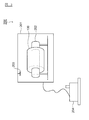
- FIG. 3 is a schematic configuration diagram of the drying apparatus. As shown in FIG. 3, the drying apparatus 200 includes a chamber 201, a support 202, a fan 203, and a vacuum pump 204.
- the chamber 201 is a container in which the roll electrode 100 is disposed in the internal space.
- the chamber 201 is a highly airtight container that prevents gas from entering the interior after decompression.
- the chamber 201 is a water-cooled chamber, and a flow path is formed in a housing portion of the chamber 201. Water circulates in a flow path from a water cooling pump (not shown).
- the support 202 supports the roll electrode 100 inside the chamber 201.
- the support 202 has a shaft heater and legs.
- the shaft heater applies heat from the inside of the roll electrode 100.
- the fan 203 is provided in the chamber 201 and is an air cooling device that cools the roll electrode 100.
- the vacuum pump 204 is a device that depressurizes the chamber 201 and places the chamber 201 in a vacuum state.
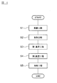
- FIG. 4 is a flowchart of the drying method according to the present embodiment.
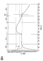
- FIG. 5 is a graph showing temperature characteristics of the roll electrode dried by the drying method according to the present embodiment.
- a graph a shown in FIG. 5 is a temperature characteristic of the outer peripheral side portion of the roll electrode 100, and a graph b is a characteristic of the internal temperature of the roll electrode 100.
- the graph réelle shows the temperature characteristics of the portion where heat is easily transmitted in the roll electrode 100
- the graph b shows the temperature characteristics of the portion where heat is hardly transmitted in the roll electrode 100.
- “S2” to “S5” shown in FIG. 5 correspond to steps “S2” to “S5” in the flowchart of FIG.
- the characteristics of the respective graphs divided from “S2” to “S5” represent the temperature transition of the roll electrode 100 in each process from step S2 to step S5 in FIG.
- the roll electrode 100 is formed by winding a plate-shaped electrode in a roll shape as a preparation stage of the electrode drying method according to the present embodiment.
- the length in the longitudinal direction of the electrode is in the range of 200 m to 900 m.
- the conditions for winding the roll electrode are such that the number of turns of the plate-like electrode is in the range from 800 to 3600 and the diameter of the roll electrode is in the range from 350 mm to 400 mm.
- Various conditions set in the following description are set in order to sufficiently remove moisture in the roll electrode 100 formed as described above.
- step S1 (arrangement step) the roll electrode 100 is supported by the support 202, and the roll electrode 100 is disposed in the chamber 201.
- a roll electrode is disposed in the chamber 201.
- the inside of the chamber 201 is in a state in which air is sealed (normal atmospheric state).
- a first temperature raising step (first heating step) is performed.
- the roll electrode 100 is heated so that the overall temperature of the roll electrode 100 is within a range between the first temperature threshold (T 1 ) and the second temperature threshold (T 2 réelle or T 2b ).
- T 1 first temperature threshold
- T 2 Second temperature threshold
- the drying apparatus 200 drives the fan 203 while turning on the shaft heater of the support 202 in a state where air is sealed in the chamber 201.
- the heating time in the first heating step is about 3 hours.
- the first temperature threshold value (T 1) in the first heating step, shows the lower limit of the target temperature range of the overall temperature of the roll electrode 100.
- the first temperature threshold (T 1 ) is the evaporation temperature of moisture in the active material included in the electrode.
- the first temperature threshold is about 90 ° C.
- the moisture in the active material is moisture taken into the crystal of the active material.
- the second temperature threshold (T 2a or T 2b ) indicates the upper limit of the target temperature range of the overall temperature of the roll electrode 100 in the first temperature raising step.
- the second temperature threshold value (T 2a ) indicates the decomposition temperature of the binding material included in the positive electrode plate.
- the binding material corresponds to an adhesive material (binder material).
- the second temperature threshold (T 2 ) is about 140 ° C.
- the second temperature threshold (T 2b ) is the melting temperature of the insulating tape. Insulating tape is used in order to prevent a short circuit between electrodes when an electrode manufactured through the drying method according to the present embodiment is incorporated into a battery.
- the insulating tape a resin adhesive tape such as polypropylene or polyphenylene sulfide is used.
- the second temperature threshold value (T 2b), the second temperature threshold value (T 2 réelle) lower than, approximately 120 ° C..
- the upper limit value of the target temperature is the second temperature threshold value (T 2b ).
- the upper limit value of the target temperature is the second temperature threshold value (T 2a ).
- the temperature of the roll electrode 100 is different depending on the shape of the roll electrode 100, the nature of the heat source of the drying apparatus 200, the position of the heat source, the heat transfer characteristics of the roll electrode 100, or the like.
- the overall temperature of the roll electrode 100 corresponds to the average temperature of the roll electrode 100, for example.
- the center part of the roll electrode 100 is the temperature of the part located between the inner diameter and the outer diameter of the roll electrode 100.
- the temperature condition of the first heating process is defined by the overall temperature of the roll electrode 100.
- the overall temperature of the roll electrode 100 is The temperature condition of one heating process is satisfied.
- the first heating step when the heating time (about 3 hours) elapses, the entire temperature of the roll electrode 100 is within the range of the first temperature threshold (T 1 ) or more and the second temperature threshold (T 2a or T 2b ) or less. If it is.
- the upper limit temperature of the target temperature range for defining the temperature condition of the first heating step is not limited to the second temperature threshold value (T 2 réelle or T 2b), it may be lower than the second temperature threshold value (T 2 réelle or T 2b) Temperature .
- the lower limit of the target temperature range is not limited to the first temperature threshold value (T 1), or at a temperature higher than the first temperature threshold value (T 1).
- the second temperature threshold value (T 2a ) is not limited to 140 ° C., and may be a temperature according to the decomposition temperature of the material used for the binding material.
- the second temperature threshold (T 2b ) may be the melting temperature of the material used for the insulating tape.
- the first temperature threshold (T 1 ) is not limited to 90 ° C., and may be a temperature according to the state characteristics of moisture contained in the electrode.
- the target temperature range is not limited to the range of 90 ° C to 120 ° C or the range of 90 ° C to 140 ° C.
- the upper limit may be within the range of 115 ° C to 145 ° C.
- the target temperature range may be appropriately set according to the temperature distribution or the like.
- the heating process (second heating process) after the first heating process includes a decompression process and a two-step heating process.
- the process including the decompression process and the first stage heating process will be described as the first vacuum process
- the second stage heating process will be described as the second vacuum process.
- a first vacuum process is performed.
- the inside of the chamber 201 is depressurized and the inside of the chamber 201 is evacuated.
- the pressure in the chamber 201 after depressurization is 600 Pa or less.
- the internal temperature of the roll electrode 100 is kept within a range equal to or lower than the first temperature threshold (T 1 ) and equal to or higher than the third temperature threshold (T 3 ).
- the roll electrode 100 is dried by maintaining the roll electrode 100.
- the internal temperature of the roll electrode 100 is the temperature of the portion of the roll electrode 100 where heat is most difficult to transfer (the portion where the temperature change amount per unit time is the smallest).
- the internal temperature of the roll electrode 100 is the temperature of the portion between the inner diameter and the outer diameter of the cross section, or the inner diameter and the outer diameter. It is the temperature of the central part between.
- the third temperature threshold value (T 3 ) is a temperature at which moisture adhering to the surface of the active material is removed and / or a temperature at which residual solvent is removed.
- the vacuum maintenance period is about 3 hours.
- the entire temperature of the roll electrode 100 is maintained within a range between the first temperature threshold value (T 1 ) and the second temperature threshold value (T 2a or T 2b ). As shown in the graph b of FIG. 5, the internal temperature of the roll electrode 100 rises from the third temperature threshold (T 3 ) as time passes, and is equal to or lower than the first temperature threshold (T 1 ). (T 3 ) The above range is maintained.
- the internal temperature of the roll electrode 100 is maintained within a range equal to or lower than the first temperature threshold (T 1 ) and equal to or higher than the third temperature threshold (T 3 ).
- Removing solvent For example, N-methyl-2-pyrrolidone (NMP) is used as the solvent. NMP solvent is used to give the viscosity of the active material, but has high affinity with water. Therefore, the solvent is combined with water adhering to the surface of the active material. When the dried electrode is incorporated as a battery with a large amount of solvent remaining in the electrode, the solvent may react with the electrolytic solution and the battery performance may be reduced.
- the internal temperature of the roll electrode 100 is raised to the third temperature threshold (T 3 ) or higher, thereby removing both the water and the solvent attached to the active material surface.
- step S4 a second vacuum process is performed.
- the roll electrode 100 is maintained by raising the internal temperature of the roll electrode 100 to the first temperature threshold (T 1 ) or higher in a vacuum state within a predetermined vacuum maintenance period (about 3 hours). .
- the entire temperature of the roll electrode 100 is maintained within a range between the first temperature threshold value (T 1 ) and the second temperature threshold value (T 2a or T 2b ).
- the temperature of the portion of the roll electrode 100 where heat is difficult to transfer becomes equal to or higher than the first temperature threshold (T 1 ), so that moisture in the active material can be removed.
- the internal temperature of the roll electrode 100 becomes equal to or higher than the first temperature threshold value (T 1 )
- PVDF softens, so that when the dried electrode is incorporated in the battery, the penetration of the electrolyte is improved, and the battery performance is improved. Can be increased.
- step S5 a cooling process is executed.
- the roll electrode 100 is forcibly cooled by operating the water cooling pump while circulating air in the chamber 201 and circulating the cooling water.
- the cooling refrigerant is not limited to air but may be nitrogen, for example.
- the roll electrode 100 is dried in a state where the entire temperature of the roll electrode 100 is within the range of the first temperature threshold (T 1 ) or less and the second temperature threshold (T 2a or T 2b ) or more. To do. Thereby, the water
- the roll electrode 100 is dried in the state which made the whole temperature of the roll electrode 100 below 2nd temperature threshold value ( T2b ). Thereby, the water
- the roll electrode 100 is dried for a predetermined period in a state where the internal temperature of the roll electrode 100 is less than the first temperature threshold (T 1 ) and within the third temperature threshold (T 3 ). After the predetermined period, the internal temperature of the roll electrode 100 is raised to the first temperature threshold (T 1 ) or higher, and the roll electrode 100 is dried. Thereby, the water
- the internal temperature of the roll electrode 100 is set to the first temperature threshold (T) while ensuring a period during which moisture and solvent in the electrode can be removed (corresponding to a vacuum maintaining period in the first vacuum process). 1 ) and less than or equal to the third temperature threshold (T 3 ). Then, after a vacuum sustain period of the first vacuum step, raising the internal temperature of the roll electrode 100 to the first temperature threshold value (T 1) or more.
- the temperature in the roll electrode 100 is increased.
- the portion for example, the portion close to the heat source
- T 2 the second temperature threshold
- the time of the vacuum process becomes longer than the time of the vacuum state in the present embodiment.
- the heating time can be shortened.
- the roll electrode 100 is dried in the state which made the whole temperature of the roll electrode 100 below 2nd temperature threshold value ( T2b ). Thereby, the time of a drying process can be shortened.
- the electrode drying method according to the second embodiment is used for drying the negative electrode.
- the method for drying a negative electrode described below is preferably applied to the drying of the negative electrode using an aqueous binder.
- the structure of the electrode for negative electrodes formed through the drying method which concerns on 2nd Embodiment, and the structure of the thin battery 1 provided with this electrode for negative electrodes are the same as that of 1st Embodiment, it is 1st The description of the embodiment is incorporated as appropriate.
- FIG. 3 is a schematic configuration diagram of the drying apparatus.
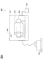
- the drying apparatus 200 includes a chamber 201, a support 202, a fan 203, a vacuum pump 204, and a nitrogen generator 205.
- the drying apparatus 200 according to the second embodiment includes: A nitrogen generator 205 is included.
- each structure of the chamber 201, the support body 202, the fan 203, and the vacuum pump 204 is the same structure as 1st Embodiment.
- the nitrogen generator 204 is a device that generates nitrogen and supplies the nitrogen to the chamber 201.
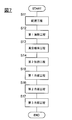
- FIG. 7 is a flowchart of the drying method according to the present embodiment.
- FIG. 8 is a graph showing temperature characteristics of the roll electrode dried by the drying method according to the present embodiment. Note that “S12” to “S17” shown in FIG. 8 correspond to steps “S12” to “S17” in the flowchart of FIG. In FIG. 8, the characteristics of the respective graphs divided from “S12” to “S17” represent the temperature transition of the roll electrode 100 in the respective steps from step S12 to step S17 in FIG.
- the roll electrode 100 is formed by winding a plate-shaped electrode in a roll shape as a preparation stage of the electrode drying method according to the present embodiment.
- the length in the longitudinal direction of the electrode is in the range of 200 m to 900 m.
- the conditions for winding the roll electrode are such that the number of turns of the plate-like electrode is in the range from 800 to 3600 and the diameter of the roll electrode is in the range from 350 mm to 400 mm.
- Various conditions set in the following description are set in order to sufficiently remove moisture in the roll electrode 100 formed as described above.
- step S11 (arrangement step) the roll electrode 100 is supported by the support 202, and the roll electrode 100 is disposed in the chamber 201.
- the vacuum pump 205 is operated in a state where the roll electrode is disposed in the chamber 201, so that the chamber 201 is brought into a vacuum state.
- step S12 the first heating step is performed.
- the roll electrode 100 is heated to raise the temperature of the roll electrode 100 to be equal to or higher than the evaporation temperature of moisture contained in the roll electrode 100.
- the drying apparatus 200 encloses nitrogen as an inert gas in the chamber 201 and drives the fan 203. Further, the drying apparatus 200 turns on the shaft heater of the support 202. Heat is transferred to the roll electrode 100 by nitrogen sealing and the operation of the fan 203.
- the heating time in the first heating step is about 2 hours.
- the target temperature (T 1 ) in the first heating step is set to be equal to or higher than the evaporation temperature of moisture contained in the roll electrode 100.
- the target temperature (T 1 ) is set to be equal to or lower than the foil burning temperature of the negative electrode plate 13 or the decomposition temperature of the additive. That is, the target temperature (T 1 ) is set in a range not lower than the water evaporation temperature and not higher than the baking temperature, or not lower than the water evaporation temperature and not higher than the decomposition temperature of the additive.
- the evaporation temperature of moisture contained in the roll electrode 100 is 120 ° C.
- the decomposition temperature of the additive and the foil burning temperature of the negative electrode plate 13 are 140 ° C., respectively.
- the target temperature (T 1 ) is in the range from 120 ° C. to 140 ° C., and is set to about 125 ° C.
- the drying apparatus 200 heats the roll electrode 100 until the temperature of the roll electrode 100 reaches the target temperature (T 1 ). Thereby, the temperature of the roll electrode 100 after heating time progresses becomes higher than 120 degreeC.
- nitrogen is added from the state in which the inside of the chamber 201 is evacuated. Therefore, since nitrogen functions as a carrier for transferring heat to the roll electrode 100, the heating time of the roll electrode 100 can be shortened. Further, the load on the chamber 201 can be reduced as compared with the case where the chamber 201 is heated in a vacuum state.
- a vacuum maintaining process is executed.
- the state in the chamber is maintained for a predetermined vacuum maintaining time.
- the drying apparatus 200 places the inside of the chamber 201 in a vacuum state and maintains the temperature of the roll electrode 100 at least higher than 120 ° C.
- the temperature of the roll electrode 100 in a vacuum maintenance process shall be less than foil baking temperature.
- the foil baking temperature is a temperature at which the metal foil forming the negative electrode plate 13 is baked. When the negative electrode plate 13 is formed of, for example, copper foil, the foil baking temperature is 140 ° C.
- the time for maintaining the vacuum state is about 3 hours. In this embodiment, the vacuum maintenance time is about 200 minutes.
- the temperature of the roll electrode 100 is maintained at a temperature higher than the water evaporation temperature (120 ° C.) and lower than the foil baking temperature (140 ° C.) in a state where the chamber 201 is evacuated.
- the vacuum state moisture attached to the electrode surface is easily detached.
- the roll electrode at a high temperature, moisture attached to the electrode surface is more easily desorbed, and moisture in the crystal is also desorbed from the crystal. The detached moisture is dried. Thereby, the water
- the negative electrode plate 13 may be oxidized (copper oxidation) by the desorbed water and oxygen. .
- an inspection process such as an image inspection is performed after drying, if the negative electrode plate 13 is oxidized, it is determined to be defective. As a result, the yield may be reduced.
- the negative electrode plate 13 is oxidized when the negative electrode plate 13 is welded, the weld strength may be reduced by the oxide film, which may result in poor welding.
- the vacuum maintaining process is performed in a state where the temperature of the roll electrode 100 is lower than the foil baking temperature, it is possible to prevent oxidation of the negative electrode plate 13 due to water desorbed from the roll electrode 100.
- a 2nd heating process is performed in step S14.
- the roll electrode 100 is further heated to raise the temperature of the roll electrode 100 to be equal to or higher than the decomposition temperature of the additive.
- the drying apparatus 200 encloses nitrogen in the chamber 201, drives the fan 203, and turns on the shaft heater of the support 202.
- the heating time in the second heating step is about 3 hours. In this embodiment, the heating time is about 220 minutes.
- the target temperature (T 2 ) in the second heating step is set to a temperature higher than the target temperature (T 1 ) and higher than the decomposition temperature of the additive.
- the target temperature (T 2 ) is set to be lower than the decomposition temperature of the binding material. That is, the target temperature (T 2 ) is set within a range that is equal to or higher than the decomposition temperature of the additive and less than the binding material.
- the decomposition temperature of the additive is 140 ° C., which is the decomposition temperature of CMC. Since the binding material uses SBR, the decomposition temperature of the binding material is set to 170 ° C., which is the decomposition temperature of SBR.
- the target temperature (T 2 ) is in the range from 140 ° C. to 170 ° C., and is set to about 168 ° C.
- the drying apparatus 200 heats the roll electrode 100 until the temperature of the roll electrode 100 reaches the target temperature (T 2 ). Further, the drying device 200 controls the shaft heater and the like so that the temperature of the roll electrode 100 does not become higher than the target temperature (T 2 ) during the heating time.
- T 2 target temperature
- the temperature of the roll electrode 100 becomes higher than the decomposition temperature of CMC, moisture is generated by the decomposition of CMC. Since the second heating step is performed in a state where nitrogen is sealed in the chamber 201, moisture generated by the decomposition of CMC remains in the negative electrode active material.
- CMC reacts with the electrolytic solution, and the battery performance may be deteriorated.
- the CMC since the CMC is decomposed by performing the second heating step, it is possible to prevent a decrease in battery performance. Further, when CMC is decomposed, a portion where CMC existed before decomposition in the electrode becomes holes. When a negative electrode with many holes is incorporated in the thin battery 1, lithium ions enter the holes. As a result, the lithium insertion efficiency is increased, and the battery performance can be improved.
- the second heating process is performed with nitrogen sealed in the chamber. Therefore, the heating time can be shortened and the load on the chamber 201 can be reduced while heat is uniformly applied to the chamber 201.
- step S15 the first cooling process is executed.
- the temperature of the roll electrode 100 is made lower than the foil baking temperature by the heat radiation of the roll electrode 100.
- the drying apparatus 200 drives the fan to enhance the cooling effect while turning off the shaft heater.
- the first cooling process is performed in a state where the nitrogen sealed in the third heating process exists in the chamber 201.
- the cooling period is about 130 minutes.
- the roll electrode 100 is set to a temperature lower than the foil baking temperature before evacuation by performing the first cooling step. Further, when evacuation is performed, if the temperature of the roll electrode 100 is high (140 ° C. or higher), copper oxidation of the negative electrode plate 13 is likely to occur. Therefore, in this embodiment, the temperature of the roll electrode 100 is set to less than 140 ° C. before evacuation to prevent copper oxidation during evacuation. Furthermore, since the fan is driven with nitrogen in the chamber 201, the cooling time can be shortened.
- step S16 the second cooling process is executed.
- the temperature of the roll electrode 100 is lowered while the chamber 201 is evacuated.
- the drying apparatus 200 performs vacuum evacuation by driving the vacuum pump 205.
- the vacuuming time is about 30 minutes.
- the drying apparatus 200 performs evacuation while keeping the temperature of the roll electrode 100 within a range from 120 ° C to 140 ° C.
- the CMC is decomposed by the heating in the second heating step and moisture is generated.
- nitrogen is contained in the chamber 201, the moisture stays in the electrode. However, by evacuation, the moisture is desorbed and the electrode is dried. Thereby, the water
- the second cooling step is performed within a range from 120 ° C. to 140 ° C., it is possible to prevent the desorbed moisture from adhering to the electrode again.
- step S17 the third cooling process is executed.
- the temperature of the roll electrode 100 is lowered while an inert gas is sealed in the chamber 201.
- the drying apparatus 200 encloses nitrogen in the chamber 201 and drives the fan 203. Further, the drying apparatus 200 drives a water cooling pump to circulate cold water in the chamber 201.
- the cooling period can be shortened by driving the fan while nitrogen is sealed in the chamber 201.
- the cooling period can be further shortened by driving the water cooling type cooling mechanism together.
- the temperature of the electrode disposed in the chamber 201 is raised to the first temperature (target temperature T 1 ), the state of the electrode is maintained for a predetermined time, and after the predetermined time has elapsed, The temperature is raised to (target temperature T 2 ).
- the drying method according to the present embodiment is a method of heating the electrode in two stages, and in the first stage heating process, the temperature of the electrode is increased to a temperature equal to or higher than the water evaporation temperature, and the second stage heating is performed. In the process, the temperature of the electrode is raised above the decomposition temperature of the additive. Thereby, the water
- the step of maintaining the electrode state performed between the first heating step and the second heating step is performed in a state where the inside of the chamber 201 is evacuated. Thereby, moisture can be desorbed from the electrode.
- the second heating step is performed in a state where an inert gas is sealed in the chamber 201. Thereby, heating time can be shortened. Further, heat can be uniformly transmitted to the roll electrode 100.
- the target temperature T 2 below the decomposition temperature of the binder material.
- the first heating step is performed in a state where an inert gas is sealed in the chamber 201. Thereby, heating time can be shortened. Further, heat can be uniformly transmitted to the roll electrode 100.
- it is set to the target temperature T 1 of less than foil burning temperature.
- the temperature of the electrode is lowered to below the foil baking temperature.
- foil burning can be prevented.
- the cooling time can be shortened compared with the case where the process is performed under vacuum.
- the electrode is cooled while the chamber 201 is evacuated. Thereby, the water
- the electrode is cooled in a state where an inert gas is sealed in the chamber 201. Thereby, cooling time can be shortened.
- the lower temperature is the upper limit temperature in the vacuum maintaining step.
- the first cooling step may be omitted or the time of the first cooling step may be shortened.
- the evacuation of the second cooling step may be performed in a temperature range (range of 100 ° C. or more and 140 ° C. or less) suitable for removing the substance generated by the CMC decomposition reaction.
- the additive contained in the negative electrode is not limited to CMC, and other materials may be used, and the binding material contained in the negative electrode is not limited to SBR but may be other materials.
- the binder of the negative electrode is not limited to a binder in which CMC and SBR are combined, and other aqueous binders may be used.
- the heating step may be performed three or more times, but it is preferable to perform the heating step twice in order to shorten the heating time. Moreover, what is necessary is just to set the time of the vacuum maintenance process performed between two heating processes according to time required in order to dry a water
Landscapes
- Engineering & Computer Science (AREA)
- Chemical & Material Sciences (AREA)
- General Chemical & Material Sciences (AREA)
- Manufacturing & Machinery (AREA)
- Chemical Kinetics & Catalysis (AREA)
- Electrochemistry (AREA)
- Mechanical Engineering (AREA)
- General Engineering & Computer Science (AREA)
- Materials Engineering (AREA)
- Life Sciences & Earth Sciences (AREA)
- Health & Medical Sciences (AREA)
- Molecular Biology (AREA)
- Microbiology (AREA)
- Battery Electrode And Active Subsutance (AREA)
- Drying Of Solid Materials (AREA)
Abstract
Description
本出願は、2016年10月11日に出願された日本国特許出願の特願2016-199979に基づく優先権を主張するものであり、文献の参照による組み込みが認められる指定国については、上記の出願に記載された内容を参照により本出願に組み込み、本出願の記載の一部とする。
本実施形態に係る電極の乾燥方法は、電池の構成部品である電極内の水分を飛ばすための方法である。乾燥の対象となる電極は、リチウムイオン電池等に用いられる。
本発明の第2実施形態に係る電極の乾燥方法を説明する。第2実施形態に電極の乾燥方法は、負極の乾燥に用いられる。以下に説明する、負極用の電極の乾燥法は、水系バインダーを使った負極の乾燥に適用することが好ましい。なお、第2実施形態に係る乾燥方法を経て形成された負極用の電極の構成、及び、この負極用の電極を備える薄型電池1の構成は、第1実施形態と同様であるため、第1実施形態の記載を適宜、援用する。
窒素発生器205を有している。なお、チャンバ201、支持体202、ファン203、真空ポンプ204の各構成は、第1実施形態と同様の構成である。窒素発生器204は、窒素を発生させて、チャンバ201に窒素を供給する装置である。
11…正極板
12…セパレータ
13…負極板
14…正極端子
15…負極端子
16、17…外装部材
17…下部外装部材
18…発電要素
100…ロール電極
200…乾燥装置
201…チャンバ
202…支持体
203…ファン
204…真空ポンプ
Claims (4)
- 正極用のロール電極を乾燥する乾燥方法であって、
前記ロール電極の全体温度を第1温度以上で第2温度以下の範囲内にした状態で、前記ロール電極を乾燥し、
前記第1温度は、前記ロール電極に含まれる活物質内の水分の蒸発温度であり、
前記第2温度は、前記ロール電極に含まれる結着性材料の分解温度である乾燥方法。 - 前記第2温度は、絶縁性テープの溶解温度以下に設定されている請求項1記載の乾燥方法。
- 前記ロール電極の内部温度を前記第1温度未満で第3温度以上の範囲内にした状態で、所定期間、前記ロール電極を乾燥し、
前記所定期間の経過後に、前記ロール電極の内部温度を前記第1温度以上に上げて、前記ロール電極を乾燥する請求項1又は2記載の乾燥方法。 - 前記電極ロールはチャンバ内に配置され、
前記チャンバ内を減圧した後に、前記全体温度を前記第1温度以上で前記第2温度以下の範囲内にした状態で、前記ロール電極を乾燥する請求項1~3のいずれか一項に記載の乾燥方法。
Priority Applications (5)
| Application Number | Priority Date | Filing Date | Title |
|---|---|---|---|
| CN201780062509.0A CN109844997A (zh) | 2016-10-11 | 2017-09-22 | 电极的干燥方法 |
| KR1020197009698A KR20190045307A (ko) | 2016-10-11 | 2017-09-22 | 전극의 건조 방법 |
| EP17860236.3A EP3528319A4 (en) | 2016-10-11 | 2017-09-22 | ELECTRODE DRYING PROCESS |
| JP2018544730A JPWO2018070218A1 (ja) | 2016-10-11 | 2017-09-22 | 電極の乾燥方法 |
| US16/340,516 US20190252670A1 (en) | 2016-10-11 | 2017-09-22 | Electrode Drying Method |
Applications Claiming Priority (2)
| Application Number | Priority Date | Filing Date | Title |
|---|---|---|---|
| JP2016199979 | 2016-10-11 | ||
| JP2016-199979 | 2016-10-11 |
Publications (1)
| Publication Number | Publication Date |
|---|---|
| WO2018070218A1 true WO2018070218A1 (ja) | 2018-04-19 |
Family
ID=61905301
Family Applications (2)
| Application Number | Title | Priority Date | Filing Date |
|---|---|---|---|
| PCT/JP2017/034301 Ceased WO2018070217A1 (ja) | 2016-10-11 | 2017-09-22 | 電極の乾燥方法 |
| PCT/JP2017/034302 Ceased WO2018070218A1 (ja) | 2016-10-11 | 2017-09-22 | 電極の乾燥方法 |
Family Applications Before (1)
| Application Number | Title | Priority Date | Filing Date |
|---|---|---|---|
| PCT/JP2017/034301 Ceased WO2018070217A1 (ja) | 2016-10-11 | 2017-09-22 | 電極の乾燥方法 |
Country Status (6)
| Country | Link |
|---|---|
| US (2) | US20200052280A1 (ja) |
| EP (2) | EP3528319A4 (ja) |
| JP (2) | JPWO2018070217A1 (ja) |
| KR (2) | KR20190045307A (ja) |
| CN (2) | CN109844997A (ja) |
| WO (2) | WO2018070217A1 (ja) |
Cited By (1)
| Publication number | Priority date | Publication date | Assignee | Title |
|---|---|---|---|---|
| US20190252670A1 (en) * | 2016-10-11 | 2019-08-15 | Nissan Motor Co., Ltd. | Electrode Drying Method |
Families Citing this family (4)
| Publication number | Priority date | Publication date | Assignee | Title |
|---|---|---|---|---|
| US10084178B2 (en) * | 2016-09-22 | 2018-09-25 | Grst International Limited | Method of preparing electrode assemblies |
| US20210143401A1 (en) * | 2019-11-08 | 2021-05-13 | Enevate Corporation | Control of thermal transfer during electrode pyrolysis based processing |
| CN114001529B (zh) * | 2021-10-30 | 2023-03-14 | 合肥众禾动力新能源科技有限公司 | 一种电芯加工过程中的辅助装置 |
| CN114659341B (zh) * | 2022-03-02 | 2023-07-07 | 上海兰钧新能源科技有限公司 | 一种用于锂离子电池烘烤的控制方法 |
Citations (4)
| Publication number | Priority date | Publication date | Assignee | Title |
|---|---|---|---|---|
| JP2011169499A (ja) | 2010-02-17 | 2011-09-01 | Nissan Motor Co Ltd | 乾燥装置及び乾燥方法 |
| JP2014107237A (ja) * | 2012-11-29 | 2014-06-09 | Meiko Electronics Co Ltd | 電極シート乾燥装置及び電極シート乾燥方法 |
| WO2015053198A1 (ja) * | 2013-10-07 | 2015-04-16 | 日産自動車株式会社 | 電極ロールの乾燥方法、および電極ロールの乾燥装置 |
| JP2016199979A (ja) | 2015-04-14 | 2016-12-01 | 立川ブラインド工業株式会社 | ロールスクリーン、案内レール、および、抜け止め部材 |
Family Cites Families (15)
| Publication number | Priority date | Publication date | Assignee | Title |
|---|---|---|---|---|
| JP2004513529A (ja) * | 2000-11-09 | 2004-04-30 | エフオーシー フランケンブルク オイル カンパニー エスト. | スーパーキャパシタおよび当該スーパーキャパシタを製造する方法 |
| JP3619870B2 (ja) * | 2001-03-07 | 2005-02-16 | 独立行政法人産業技術総合研究所 | リチウムイオン二次電池用負電極板の製造方法 |
| JP4739711B2 (ja) * | 2004-08-31 | 2011-08-03 | 三洋電機株式会社 | 非水電解質二次電池の製造方法及び非水電解質二次電池用電極板乾燥装置 |
| JP4904807B2 (ja) * | 2005-12-27 | 2012-03-28 | Tdk株式会社 | 電気化学キャパシタ用電極の製造方法及び電気化学キャパシタ用電極の製造装置 |
| JP2009236355A (ja) * | 2008-03-26 | 2009-10-15 | Fujifilm Corp | 乾燥方法及び装置 |
| JP5272564B2 (ja) * | 2008-08-04 | 2013-08-28 | 日産自動車株式会社 | 電極材乾燥方法および電極材乾燥装置 |
| CN102147185B (zh) * | 2010-12-10 | 2012-11-28 | 奇瑞汽车股份有限公司 | 锂离子二次电池极片的干燥方法 |
| JP2017021888A (ja) * | 2013-11-25 | 2017-01-26 | 日産自動車株式会社 | 非水電解質二次電池用負極の製造方法 |
| DE102014008742A1 (de) * | 2014-06-12 | 2015-12-17 | Daimler Ag | Separator für einen elektrochemischen Speicher, Verfahren zur Herstellung eines Elektrodenmaterials sowie elektrochemischer Energiespeicher |
| JP2016065649A (ja) * | 2014-09-22 | 2016-04-28 | 株式会社Screenホールディングス | 乾燥装置、塗工膜形成装置、および乾燥方法 |
| JP6492583B2 (ja) * | 2014-11-28 | 2019-04-03 | 株式会社豊田自動織機 | 電極の製造方法 |
| US10254043B2 (en) * | 2016-09-22 | 2019-04-09 | Grst International Limited | Method of drying electrode assemblies |
| WO2018070217A1 (ja) * | 2016-10-11 | 2018-04-19 | 日産自動車株式会社 | 電極の乾燥方法 |
| US9966591B1 (en) * | 2016-12-19 | 2018-05-08 | StoreDot Ltd. | Electrode stack production methods |
| US10033023B2 (en) * | 2016-12-19 | 2018-07-24 | StoreDot Ltd. | Surface activation in electrode stack production and electrode-preparation systems and methods |
-
2017
- 2017-09-22 WO PCT/JP2017/034301 patent/WO2018070217A1/ja not_active Ceased
- 2017-09-22 US US16/340,613 patent/US20200052280A1/en not_active Abandoned
- 2017-09-22 CN CN201780062509.0A patent/CN109844997A/zh active Pending
- 2017-09-22 US US16/340,516 patent/US20190252670A1/en not_active Abandoned
- 2017-09-22 EP EP17860236.3A patent/EP3528319A4/en not_active Withdrawn
- 2017-09-22 KR KR1020197009698A patent/KR20190045307A/ko not_active Ceased
- 2017-09-22 CN CN201780062989.0A patent/CN109863627A/zh active Pending
- 2017-09-22 KR KR1020197010381A patent/KR20190047015A/ko not_active Ceased
- 2017-09-22 EP EP17860030.0A patent/EP3528318A4/en not_active Withdrawn
- 2017-09-22 WO PCT/JP2017/034302 patent/WO2018070218A1/ja not_active Ceased
- 2017-09-22 JP JP2018544729A patent/JPWO2018070217A1/ja active Pending
- 2017-09-22 JP JP2018544730A patent/JPWO2018070218A1/ja active Pending
Patent Citations (4)
| Publication number | Priority date | Publication date | Assignee | Title |
|---|---|---|---|---|
| JP2011169499A (ja) | 2010-02-17 | 2011-09-01 | Nissan Motor Co Ltd | 乾燥装置及び乾燥方法 |
| JP2014107237A (ja) * | 2012-11-29 | 2014-06-09 | Meiko Electronics Co Ltd | 電極シート乾燥装置及び電極シート乾燥方法 |
| WO2015053198A1 (ja) * | 2013-10-07 | 2015-04-16 | 日産自動車株式会社 | 電極ロールの乾燥方法、および電極ロールの乾燥装置 |
| JP2016199979A (ja) | 2015-04-14 | 2016-12-01 | 立川ブラインド工業株式会社 | ロールスクリーン、案内レール、および、抜け止め部材 |
Non-Patent Citations (1)
| Title |
|---|
| See also references of EP3528319A4 |
Cited By (1)
| Publication number | Priority date | Publication date | Assignee | Title |
|---|---|---|---|---|
| US20190252670A1 (en) * | 2016-10-11 | 2019-08-15 | Nissan Motor Co., Ltd. | Electrode Drying Method |
Also Published As
| Publication number | Publication date |
|---|---|
| EP3528318A4 (en) | 2019-10-30 |
| US20190252670A1 (en) | 2019-08-15 |
| CN109863627A (zh) | 2019-06-07 |
| EP3528319A4 (en) | 2019-10-30 |
| CN109844997A (zh) | 2019-06-04 |
| WO2018070217A1 (ja) | 2018-04-19 |
| EP3528319A1 (en) | 2019-08-21 |
| JPWO2018070217A1 (ja) | 2019-08-08 |
| EP3528318A1 (en) | 2019-08-21 |
| US20200052280A1 (en) | 2020-02-13 |
| JPWO2018070218A1 (ja) | 2019-08-29 |
| KR20190047015A (ko) | 2019-05-07 |
| KR20190045307A (ko) | 2019-05-02 |
Similar Documents
| Publication | Publication Date | Title |
|---|---|---|
| JP6202347B2 (ja) | 非水電解液二次電池 | |
| JP5888551B2 (ja) | 密閉型リチウム二次電池の製造方法 | |
| JP5818116B2 (ja) | 密閉型リチウム二次電池とその製造方法 | |
| JP6636012B2 (ja) | 加圧部を含む円筒型電池及びその製造方法 | |
| US10396352B2 (en) | Non-aqueous electrolyte battery, method for manufacturing same, and non-aqueous electrolyte battery system | |
| JP6210336B2 (ja) | 二次電池 | |
| JPWO2018070218A1 (ja) | 電極の乾燥方法 | |
| CN106025337A (zh) | 锂离子二次电池和使用其的系统 | |
| JP2016085941A (ja) | 非水電解液二次電池および該電池に用いられる電極体 | |
| JP6410847B2 (ja) | 電気化学セルを製造する方法 | |
| JP5348720B2 (ja) | 扁平形非水二次電池 | |
| JP2019160553A (ja) | 電極及び蓄電素子 | |
| JP2010232011A (ja) | 二次電池 | |
| KR20170094916A (ko) | 전극조립체 제조방법 및 이를 사용하여 제조되는 전극조립체 | |
| JP2017027837A (ja) | リチウムイオン二次電池 | |
| JP2017054739A (ja) | 二次電池 | |
| JP2018018785A (ja) | 非水電解質二次電池 | |
| KR101307772B1 (ko) | 이차전지 제조방법 및 이를 이용하여 생산되는 이차전지 | |
| JP2017004729A (ja) | 非水電解質二次電池 | |
| JP2015138717A (ja) | リチウム二次電池 | |
| JP2004311339A (ja) | 非水電解質二次電池 | |
| JP2008226555A (ja) | 非水電解質電池 | |
| JP4710276B2 (ja) | 二次電池用外装部材及び二次電池 | |
| JP2019175632A (ja) | 活物質、電極及びリチウムイオン二次電池 | |
| KR101483332B1 (ko) | 전극조립체 및 이를 포함하는 전기 화학 소자 |
Legal Events
| Date | Code | Title | Description |
|---|---|---|---|
| 121 | Ep: the epo has been informed by wipo that ep was designated in this application |
Ref document number: 17860236 Country of ref document: EP Kind code of ref document: A1 |
|
| ENP | Entry into the national phase |
Ref document number: 2018544730 Country of ref document: JP Kind code of ref document: A Ref document number: 20197009698 Country of ref document: KR Kind code of ref document: A |
|
| NENP | Non-entry into the national phase |
Ref country code: DE |
|
| ENP | Entry into the national phase |
Ref document number: 2017860236 Country of ref document: EP Effective date: 20190513 |