WO2018070277A1 - 空気入りタイヤ - Google Patents
空気入りタイヤ Download PDFInfo
- Publication number
- WO2018070277A1 WO2018070277A1 PCT/JP2017/035563 JP2017035563W WO2018070277A1 WO 2018070277 A1 WO2018070277 A1 WO 2018070277A1 JP 2017035563 W JP2017035563 W JP 2017035563W WO 2018070277 A1 WO2018070277 A1 WO 2018070277A1
- Authority
- WO
- WIPO (PCT)
- Prior art keywords
- tire
- belt
- vehicle
- width direction
- circumferential
- Prior art date
- Legal status (The legal status is an assumption and is not a legal conclusion. Google has not performed a legal analysis and makes no representation as to the accuracy of the status listed.)
- Ceased
Links
Images


Classifications
-
- B—PERFORMING OPERATIONS; TRANSPORTING
- B60—VEHICLES IN GENERAL
- B60C—VEHICLE TYRES; TYRE INFLATION; TYRE CHANGING; CONNECTING VALVES TO INFLATABLE ELASTIC BODIES IN GENERAL; DEVICES OR ARRANGEMENTS RELATED TO TYRES
- B60C9/00—Reinforcements or ply arrangement of pneumatic tyres
- B60C9/18—Structure or arrangement of belts or breakers, crown-reinforcing or cushioning layers
- B60C9/20—Structure or arrangement of belts or breakers, crown-reinforcing or cushioning layers built-up from rubberised plies each having all cords arranged substantially parallel
- B60C9/2003—Structure or arrangement of belts or breakers, crown-reinforcing or cushioning layers built-up from rubberised plies each having all cords arranged substantially parallel characterised by the materials of the belt cords
- B60C9/2006—Structure or arrangement of belts or breakers, crown-reinforcing or cushioning layers built-up from rubberised plies each having all cords arranged substantially parallel characterised by the materials of the belt cords consisting of steel cord plies only
-
- B—PERFORMING OPERATIONS; TRANSPORTING
- B60—VEHICLES IN GENERAL
- B60C—VEHICLE TYRES; TYRE INFLATION; TYRE CHANGING; CONNECTING VALVES TO INFLATABLE ELASTIC BODIES IN GENERAL; DEVICES OR ARRANGEMENTS RELATED TO TYRES
- B60C11/00—Tyre tread bands; Tread patterns; Anti-skid inserts
- B60C11/03—Tread patterns
- B60C11/0304—Asymmetric patterns
-
- B—PERFORMING OPERATIONS; TRANSPORTING
- B60—VEHICLES IN GENERAL
- B60C—VEHICLE TYRES; TYRE INFLATION; TYRE CHANGING; CONNECTING VALVES TO INFLATABLE ELASTIC BODIES IN GENERAL; DEVICES OR ARRANGEMENTS RELATED TO TYRES
- B60C11/00—Tyre tread bands; Tread patterns; Anti-skid inserts
-
- B—PERFORMING OPERATIONS; TRANSPORTING
- B60—VEHICLES IN GENERAL
- B60C—VEHICLE TYRES; TYRE INFLATION; TYRE CHANGING; CONNECTING VALVES TO INFLATABLE ELASTIC BODIES IN GENERAL; DEVICES OR ARRANGEMENTS RELATED TO TYRES
- B60C11/00—Tyre tread bands; Tread patterns; Anti-skid inserts
- B60C11/0083—Tyre tread bands; Tread patterns; Anti-skid inserts characterised by the curvature of the tyre tread
-
- B—PERFORMING OPERATIONS; TRANSPORTING
- B60—VEHICLES IN GENERAL
- B60C—VEHICLE TYRES; TYRE INFLATION; TYRE CHANGING; CONNECTING VALVES TO INFLATABLE ELASTIC BODIES IN GENERAL; DEVICES OR ARRANGEMENTS RELATED TO TYRES
- B60C11/00—Tyre tread bands; Tread patterns; Anti-skid inserts
- B60C11/03—Tread patterns
-
- B—PERFORMING OPERATIONS; TRANSPORTING
- B60—VEHICLES IN GENERAL
- B60C—VEHICLE TYRES; TYRE INFLATION; TYRE CHANGING; CONNECTING VALVES TO INFLATABLE ELASTIC BODIES IN GENERAL; DEVICES OR ARRANGEMENTS RELATED TO TYRES
- B60C5/00—Inflatable pneumatic tyres or inner tubes
-
- B—PERFORMING OPERATIONS; TRANSPORTING
- B60—VEHICLES IN GENERAL
- B60C—VEHICLE TYRES; TYRE INFLATION; TYRE CHANGING; CONNECTING VALVES TO INFLATABLE ELASTIC BODIES IN GENERAL; DEVICES OR ARRANGEMENTS RELATED TO TYRES
- B60C9/00—Reinforcements or ply arrangement of pneumatic tyres
- B60C9/18—Structure or arrangement of belts or breakers, crown-reinforcing or cushioning layers
- B60C9/20—Structure or arrangement of belts or breakers, crown-reinforcing or cushioning layers built-up from rubberised plies each having all cords arranged substantially parallel
- B60C9/22—Structure or arrangement of belts or breakers, crown-reinforcing or cushioning layers built-up from rubberised plies each having all cords arranged substantially parallel the plies being arranged with all cords disposed along the circumference of the tyre
-
- B—PERFORMING OPERATIONS; TRANSPORTING
- B60—VEHICLES IN GENERAL
- B60C—VEHICLE TYRES; TYRE INFLATION; TYRE CHANGING; CONNECTING VALVES TO INFLATABLE ELASTIC BODIES IN GENERAL; DEVICES OR ARRANGEMENTS RELATED TO TYRES
- B60C9/00—Reinforcements or ply arrangement of pneumatic tyres
- B60C9/18—Structure or arrangement of belts or breakers, crown-reinforcing or cushioning layers
- B60C9/28—Structure or arrangement of belts or breakers, crown-reinforcing or cushioning layers characterised by the belt or breaker dimensions or curvature relative to carcass
-
- B—PERFORMING OPERATIONS; TRANSPORTING
- B60—VEHICLES IN GENERAL
- B60C—VEHICLE TYRES; TYRE INFLATION; TYRE CHANGING; CONNECTING VALVES TO INFLATABLE ELASTIC BODIES IN GENERAL; DEVICES OR ARRANGEMENTS RELATED TO TYRES
- B60C11/00—Tyre tread bands; Tread patterns; Anti-skid inserts
- B60C11/0008—Tyre tread bands; Tread patterns; Anti-skid inserts characterised by the tread rubber
- B60C2011/0016—Physical properties or dimensions
- B60C2011/0033—Thickness of the tread
-
- B—PERFORMING OPERATIONS; TRANSPORTING
- B60—VEHICLES IN GENERAL
- B60C—VEHICLE TYRES; TYRE INFLATION; TYRE CHANGING; CONNECTING VALVES TO INFLATABLE ELASTIC BODIES IN GENERAL; DEVICES OR ARRANGEMENTS RELATED TO TYRES
- B60C11/00—Tyre tread bands; Tread patterns; Anti-skid inserts
- B60C11/03—Tread patterns
- B60C2011/0337—Tread patterns characterised by particular design features of the pattern
- B60C2011/0339—Grooves
- B60C2011/0341—Circumferential grooves
- B60C2011/0353—Circumferential grooves characterised by width
-
- B—PERFORMING OPERATIONS; TRANSPORTING
- B60—VEHICLES IN GENERAL
- B60C—VEHICLE TYRES; TYRE INFLATION; TYRE CHANGING; CONNECTING VALVES TO INFLATABLE ELASTIC BODIES IN GENERAL; DEVICES OR ARRANGEMENTS RELATED TO TYRES
- B60C11/00—Tyre tread bands; Tread patterns; Anti-skid inserts
- B60C11/03—Tread patterns
- B60C2011/0337—Tread patterns characterised by particular design features of the pattern
- B60C2011/0339—Grooves
- B60C2011/0341—Circumferential grooves
- B60C2011/0355—Circumferential grooves characterised by depth
-
- B—PERFORMING OPERATIONS; TRANSPORTING
- B60—VEHICLES IN GENERAL
- B60C—VEHICLE TYRES; TYRE INFLATION; TYRE CHANGING; CONNECTING VALVES TO INFLATABLE ELASTIC BODIES IN GENERAL; DEVICES OR ARRANGEMENTS RELATED TO TYRES
- B60C2200/00—Tyres specially adapted for particular applications
- B60C2200/06—Tyres specially adapted for particular applications for heavy duty vehicles
-
- B—PERFORMING OPERATIONS; TRANSPORTING
- B60—VEHICLES IN GENERAL
- B60C—VEHICLE TYRES; TYRE INFLATION; TYRE CHANGING; CONNECTING VALVES TO INFLATABLE ELASTIC BODIES IN GENERAL; DEVICES OR ARRANGEMENTS RELATED TO TYRES
- B60C9/00—Reinforcements or ply arrangement of pneumatic tyres
- B60C9/18—Structure or arrangement of belts or breakers, crown-reinforcing or cushioning layers
- B60C9/30—Structure or arrangement of belts or breakers, crown-reinforcing or cushioning layers asymmetric to the midcircumferential plane of the tyre
Definitions
- the present invention relates to a pneumatic tire.
- Patent Document 1 describes an asymmetric pneumatic tire that improves the wear resistance of a shoulder portion.
- the tread portion in which the carcass and the reinforcing belt layer each have a symmetrical structure with respect to the wheel center surface has an asymmetric shape, and the maximum outer diameter point is the wheel center surface and one tread in the contour shape of the tread portion.
- the distance between the maximum outer diameter point and the wheel center plane is approximately 1/10 of the maximum tire width, and the shape of the tread portion located on both sides of the maximum outer diameter point is 2 when One of was approximated by a circular arc, the radius of curvature R 2 of the narrow portion, is greater than the radius of curvature R 3 of the wide portion of, and that both arcs have a common tangent at maximum outer ⁇ , both curvature
- the difference R 2 ⁇ R 3 between the radii R 2 and R 3 is approximately 1/6 of the maximum outer diameter of the tire.
- Patent Document 2 describes a pneumatic tire that improves the uneven wear resistance of a tire with respect to uneven wear due to accelerated wear of a tread rubber in a shoulder portion.
- This pneumatic tire is a pneumatic tire in which a plurality of reinforcing layers and a tread are arranged in order on the radially outer side of a crown portion of a carcass straddling a toroidal shape between a pair of bead portions, and is attached to a specified rim.
- the reinforcing layer located on the outermost side in the tire radial direction among the plurality of reinforcing layers is curved convexly outward in the tire radial direction in at least one half of the tire width direction. And extending inward in the tire radial direction from the top of the curved portion toward the end of the outermost reinforcing layer.
- the distance in the tire radial direction between the outermost reinforcing layer and the outer contour line, which is a virtual line when the tread surface is not uneven, is from the tire equatorial plane to the top of the curved portion in the tire width direction. And gradually increase from the top of the curved portion to the end of the outermost reinforcing layer.
- a single-mounted pneumatic tire has a wider tread deployment width than a dual-mounted pneumatic tire, so there is a large difference in contact pressure in each region in the tire width direction, and uneven wear tends to occur. Yes.
- the shoulder drop in the shoulder region during inflation is large, the contact pressure is relatively low compared to the center region, and slippage is increased, and uneven wear tends to occur in the shoulder region.
- the camber angle of the wheel is often set to a positive camber.
- the ground pressure near the shoulder inside the vehicle when the vehicle is mounted is the ground pressure near the shoulder outside the vehicle. It tends to be lower than the pressure.
- the contact pressure is low, the diameter growth due to the rotation of the wheel during traveling of the vehicle increases, and therefore, the diameter growth near the shoulder portion on the vehicle inner side tends to be larger than the vicinity of the shoulder portion on the vehicle outer side.
- the diameter growth increases, the degree of rubbing of the tread surface against the road surface during rotation of the wheel increases, and thus wear easily occurs.
- the present invention has been made in view of the above, and an object of the present invention is to provide a pneumatic tire capable of improving the resistance to uneven shoulder wear.
- the pneumatic tire according to one aspect of the present invention is designated in the direction of the inside and outside of the vehicle when the vehicle is mounted, and the tread portion extends along the tire circumferential direction.
- a tread gauge extending from the tread surface of the tread portion to the belt layer is equal between the vehicle outer side and the vehicle inner side in a range where the circumferential belt layer is disposed, while from the tire equatorial plane
- the belt ply on the outermost side in the tire radial direction is positioned 120% away from the outer side of the vehicle and the inner side of the vehicle with respect to 1/2 the tire width direction dimension of the circumferential belt layer.
- Outside the vehicle gauge H1out and the vehicle inner side of the gauge H1in is a 1mm ⁇ H1in-H1out ⁇ 3mm.
- the tread gauge on the vehicle inner side is configured to be thicker than the vehicle outer side near the shoulder portion near the end of the belt layer in the tire width direction. For this reason, the amount of shoulder drop near the shoulder on the inside of the vehicle during inflation is less than that on the outside of the vehicle, so the difference in ground contact pressure relative to other parts is reduced, and the slip difference between the tread surfaces is reduced. Can be kept small. As a result, it is possible to reduce the friction energy in the vicinity of the shoulder portion on the inner side of the vehicle and improve the resistance to uneven shoulder wear.
- the gauge H2out on the vehicle outer side and the gauge H2in on the vehicle inner side of 1 mm are provided at the shortest distance from the ground contact end of the tread portion to the belt ply having the maximum dimension in the tire width direction.
- ⁇ H2in ⁇ H2out ⁇ 3 mm is preferable.
- the tread gauge on the vehicle inner side is configured to be thicker than the vehicle outer side near the ground contact end. For this reason, the amount of shoulder drop near the shoulder on the inside of the vehicle during inflation is less than that on the outside of the vehicle, so the difference in ground contact pressure relative to other parts is reduced, and the slip difference between the tread surfaces is reduced. Can be kept small. As a result, it is possible to reduce the friction energy in the vicinity of the shoulder portion on the inner side of the vehicle and to further improve the shoulder uneven wear resistance.
- a plurality of circumferential main grooves extending in the tire circumferential direction and juxtaposed in the tire width direction are formed on the tread surface, and the outermost tire width direction is formed. It is preferable that a tire width direction inner dimension Wr of each of the circumferential main grooves and a tire width direction dimension W of the circumferential belt layer satisfy 0.9 ⁇ W / Wr ⁇ 1.1.
- the circumferential belt layer is arranged on the inner side in the tire radial direction of all the land portions except the outermost land portion in the tire width direction to suppress the radial growth.
- the shoulder uneven wear resistance can be further improved.
- the tire width direction distance from the tire equatorial plane to the end of the circumferential belt layer in a no-load state in which the rim is assembled to the normal rim and the normal internal pressure is filled.
- the tire radial direction dimension D with respect to the line L2 is preferably 0.01 ⁇ D / W1 ⁇ 0.05.
- the difference from the tire radial direction maximum position of the tread surface in the range of the tire width direction distance W1 of the circumferential belt layer from the tire equator surface is 0.01 ⁇ D / W1 ⁇ 0.05.
- the effect of suppressing the radial growth in the range of the dimension in the tire width direction of the circumferential belt layer becomes remarkable.
- the pneumatic tire according to one aspect of the present invention is preferably a heavy-duty single-mounted tire having a nominal width of 355 mm or more, a flatness ratio of 55% or less, and a rim diameter of 17.5 inches or more.
- the single mounting method using one wheel is employed instead of using dual mounting in which two wheels are stacked in the vehicle width direction on each end side of the drive shaft and trailer shaft.
- the effect of improving the shoulder uneven wear resistance can be remarkably obtained by being applied to a single tire for heavy load having a size.
- the relationship between the gauge H1out on the vehicle outer side and the gauge H1in on the vehicle inner side is such that the belt layer is symmetrically arranged in the tire width direction centering on the tire equatorial plane.
- the tread surface profile is preferably made different in the tire width direction around the tire equator surface.
- This pneumatic tire can be manufactured without changing the mold that forms the tread surface only.
- the relationship between the gauge H1out on the vehicle outer side and the gauge H1in on the vehicle inner side is symmetrical with the profile of the tread surface in the tire width direction centering on the tire equatorial plane.
- the belt layers are arranged differently in the tire width direction around the tire equatorial plane.
- This pneumatic tire can be manufactured without changing the configuration of the belt layer and changing the mold forming the tread surface.
- the relationship between the gauge H1out on the vehicle outer side and the gauge H1in on the vehicle inner side is different in the profile of the tread surface in the tire width direction around the tire equatorial plane. It is preferable that the arrangement of the belt layer is made different in the tire width direction around the tire equatorial plane.
- the profile of the tread surface and the arrangement of the belt layer can be obtained by obtaining the relationship between the gauge H1out on the vehicle outer side and the gauge H1in on the vehicle inner side by changing the profile of the tread surface and the arrangement of the belt layer. It is possible to obtain an effect of improving shoulder uneven wear resistance while suppressing a situation in which the vehicle outer side and the vehicle inner side are largely biased and different.
- the resistance to uneven shoulder wear can be improved.
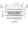
- FIG. 1 is a meridional sectional view of a pneumatic tire according to an embodiment of the present invention.
- FIG. 2 is a partial development view of the belt layer of the pneumatic tire according to the embodiment of the present invention.
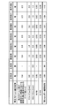
- FIG. 3 is a chart showing the results of the performance test of the pneumatic tire according to the example of the present invention.
- FIG. 4 is a chart showing the results of the performance test of the pneumatic tire according to the example of the present invention.
- FIG. 1 is a meridional sectional view of a pneumatic tire according to this embodiment.
- FIG. 2 is a partial development view of the belt layer of the pneumatic tire according to the present embodiment.
- the tire radial direction refers to a direction orthogonal to the rotation axis (not shown) of the pneumatic tire 1
- the tire radial direction inner side refers to the side toward the rotation axis in the tire radial direction, the tire radial direction outer side.
- the tire width direction means a direction parallel to the rotation axis, the inner side in the tire width direction is the side toward the tire equatorial plane CL in the tire width direction, and the outer side in the tire width direction is the tire equatorial plane CL in the tire width direction. The side away from.
- the tire circumferential direction refers to a direction around the rotation axis as a central axis.
- the tire equatorial plane CL is a plane that is orthogonal to the rotational axis of the pneumatic tire 1 and that passes through the center of the tire width of the pneumatic tire 1.
- the tire width is the width in the tire width direction between the portions located outside in the tire width direction, that is, the distance between the portions farthest from the tire equatorial plane CL in the tire width direction.
- the pneumatic tire 1 includes a tread portion 2, shoulder portions 4 on both sides of the tread portion 2, and sidewall portions 5 and bead portions 6 that are sequentially continuous from the shoulder portions 4.
- the pneumatic tire 1 includes a carcass layer 7, a belt layer 8, and an inner liner layer 9.
- the tread portion 2 is made of a rubber material (tread rubber) and is exposed at the outermost side in the tire radial direction of the pneumatic tire 1, and the surface thereof is the contour of the pneumatic tire 1.
- the tread portion 2 is formed on the outer peripheral surface of the tread portion 3 as a tread surface 3 that comes into contact with the road surface when a vehicle (not shown) on which the pneumatic tire 1 is mounted travels.
- the tread surface 3 is formed with a circumferential main groove 10 extending in the tire circumferential direction.
- a plurality of circumferential main grooves 10 are provided side by side in the tire width direction.
- the tread surface 3 may be formed with a plurality of lug grooves that intersect in the tire circumferential direction.
- the tread surface 3 has a plurality of land portions 11 defined by these circumferential main grooves 10 and lug grooves.
- the circumferential main groove 10 is a groove extending in the tire circumferential direction having a groove width of 6 mm to 14 mm and a groove depth of 10 mm to 26 mm. Further, the circumferential main groove 10 may be curved or bent in the tire width direction while extending in the tire circumferential direction. In the present embodiment, the circumferential main grooves 10 are arranged symmetrically in the tire width direction with the tire equatorial plane CL as a boundary.
- the shoulder portion 4 is a portion of the tread portion 2 on both outer sides in the tire width direction. Further, the sidewall portion 5 is exposed at the outermost side in the tire width direction of the pneumatic tire 1.
- the bead portion 6 includes a bead core 61 and a bead filler 62.
- the bead core 61 is formed by winding a bead wire, which is a steel wire, in a ring shape.
- the bead filler 62 is a rubber material that is disposed in a space formed on the outer side in the tire radial direction of the bead core 61 by folding the end portion in the tire width direction of the carcass layer 7 at the position of the bead core 61.
- the carcass layer 7 is configured such that the ends in the tire width direction are folded back from the inner side in the tire width direction to the outer side in the tire width direction by a pair of bead cores 61 and are wound around in a toroidal shape in the tire circumferential direction. It is.
- the carcass layer 7 includes a plurality of carcass cords arranged side by side with an angle (for example, an absolute value of ⁇ 85 ° to ⁇ 95 °) that is in the tire circumferential direction while an angle with respect to the tire circumferential direction is along the tire meridian direction. (Not shown) is covered with a coat rubber and rolled.
- the carcass cord is made of steel or an organic fiber material (polyester, rayon, nylon, etc.).
- the carcass layer 7 is provided as at least one layer.
- the belt layer 8 has a multilayer structure in which a plurality of belt plies 81, 82, 83, 84, and 85 (in this embodiment, five) are laminated in the tire radial direction, and on the outer periphery of the carcass layer 7 in the tread portion 2. It is arrange
- Each of the belt plies 81, 82, 83, 84, 85 is formed by coating a plurality of belt cords 811, 821, 831, 841, 851 (see FIG. 2) arranged in parallel at an angle in the tire circumferential direction with a coat rubber. Constructed by rolling.
- the belt cords 811, 821, 831, 841, 851 are made of steel or an organic fiber material (polyester, rayon, nylon, etc.).
- the inner liner layer 9 is the inner surface of the tire, that is, the inner peripheral surface of the carcass layer 7, and both ends in the tire width direction reach the lower portion of the bead core 61 of the pair of bead portions 6 and the bead toe, and the toroid in the tire circumferential direction. It is hung around and pasted.
- the inner liner layer 9 is for suppressing the permeation of air molecules and does not have a cord.
- the belt layer 8 has a multilayer structure in which a plurality of belt plies 81, 82, 83, 84, 85 are laminated in the tire radial direction. More specifically, the belt layer 8 includes belt plies 81, 82, 83, 84, 85 as a high-angle belt 81, an inner cross belt 82, a circumferential belt layer 83, and an outer cross belt 84 from the inner side in the tire radial direction. And a belt cover 85.
- the high-angle belt 81 is continuously arranged on both sides in the tire width direction on the tire equatorial plane CL, and is formed by rolling a plurality of belt cords 811 with a coat rubber.
- the belt cord 811 has a belt angle that is an inclination angle with respect to the tire circumferential direction in an absolute value of ⁇ 45 ° to ⁇ 70 °.
- the inner cross belt 82 is continuously arranged on both sides in the tire width direction on the tire equatorial plane CL, and is formed by covering a plurality of belt cords 821 with a coat rubber and rolling.
- the belt cord 821 has a belt angle, which is an inclination angle with respect to the tire circumferential direction, in an absolute value of ⁇ 10 ° to ⁇ 45 °.
- the circumferential belt layer 83 is continuously arranged on both sides in the tire width direction on the tire equator plane CL, and is formed by rolling a plurality of belt cords 831 with a coat rubber.
- the belt cord 831 is provided with a belt angle, which is an inclination angle with respect to the tire circumferential direction, having an absolute value of ⁇ 5 ° and spirally wound, and is disposed substantially along the tire circumferential direction.
- the outer cross belt 84 is continuously arranged on both sides in the tire width direction on the tire equatorial plane CL, and a plurality of belt cords 841 are covered with coat rubber and rolled.
- the belt cord 841 has a belt angle that is an inclination angle with respect to the tire circumferential direction in an absolute value of ⁇ 10 ° to ⁇ 45 °.
- the belt cover 85 is continuously disposed on both sides in the tire width direction on the tire equatorial plane CL, and is formed by rolling a plurality of belt cords 851 with a coat rubber.
- the belt cord 851 has a belt angle that is an inclination angle with respect to the tire circumferential direction in an absolute value of ⁇ 10 ° to ⁇ 45 °.
- the inclination directions of the belt cords 821 and 841 are opposite to each other. That is, the inner cross belt 82 and the outer cross belt 84 are laminated so that the inclination directions of the belt cords 821 and 841 cross each other, have a so-called cross ply structure, and are provided as a pair of cross belt layers. .
- the inner cross belt 82 and the outer cross belt 84 provided as the cross belt layer are provided with different sizes in the tire width direction
- the high-angle belt 81 is inclined by the belt cord 811 with respect to the belt cord 821 of the inner cross belt 82 that overlaps the outer side in the tire radial direction.
- the directions are provided in the same direction.
- the high-angle belt 81 is narrower in the tire width direction dimension than the inner cross belt 82 and is disposed within the tire width direction dimension of the inner cross belt 82.
- the belt cover 85 is provided such that the inclination direction of the belt cord 851 is the same as the belt cord 841 of the outer cross belt 84 that overlaps the inner side in the tire radial direction.
- the belt cover 85 is provided with a narrower width in the tire width direction than the outer cross belt 84, and is disposed within the range of the tire cross direction dimension of the outer cross belt 84.
- the circumferential belt layer 83 is provided between the inner cross belt 82 and the outer cross belt 84.
- the circumferential belt layer 83 is narrower in the tire width direction than the narrow outer cross belt 84 in the inner cross belt 82 and the outer cross belt 84 that are cross belt layers, and the inner cross belt 82 and the outer cross belt 82. It is arranged within a range of 84 tire width direction dimensions.
- the direction with respect to the inner side and the outer side of the vehicle is specified in the tire width direction, that is, the direction inside and outside the vehicle when the vehicle is mounted is specified.
- the designation of the direction is not clearly shown in the figure, but is indicated by, for example, an index provided on the sidewall portion 5.
- the index is constituted by, for example, a mark or unevenness attached to the sidewall portion 5 of the tire.
- ECER 54 (Article 54 of the European Economic Commission Regulations) obligates the installation to the side wall portion 5 that is on the vehicle outer side when the vehicle is mounted.
- the designation of the vehicle inner side and the vehicle outer side is not limited to the case where the vehicle is mounted on the vehicle.
- the direction of the rim with respect to the inside and outside of the vehicle is determined in the tire width direction.
- the orientation with respect to the vehicle inner side and the vehicle outer side is designated in the tire width direction.
- the pneumatic tire 1 of the present embodiment is a heavy duty pneumatic tire that is mounted on a drive shaft or trailer shaft of a large vehicle such as a truck or bus for long-distance transportation.
- the pneumatic tire 1 of the present embodiment is a heavy-duty pneumatic tire (single-mounted heavy load) that is single-mounted on each end of a drive shaft or trailer shaft of a large vehicle such as a truck or bus for long-distance transportation. Tire).
- the tread gauge extending from the tread surface 3 of the tread portion 2 to the belt layer 8 is defined as follows. First, the tread gauge is equally formed on the vehicle outer side and the vehicle inner side in a range where the circumferential belt layer 83 is disposed (a range of dimensions in the tire width direction between the end portions 83a of the circumferential belt layer 83). This “equal” means that the difference in distance from the tread surface 3 to the outermost position in the tire radial direction of the belt layer 8 is 1 mm or less at each position at the same distance from the tire equatorial plane CL to the vehicle outer side and the vehicle inner side. Means that.
- the tread gauge is a tire at each position 120% away from the tire equatorial plane CL to the vehicle outer side and the vehicle inner side with respect to 1/2 of the tire width direction dimension W between the end portions 83a of the circumferential belt layer 83.
- a gauge H1out on the vehicle outer side and a gauge H1in on the vehicle inner side in the radially outermost belt ply (shown as the outer cross belt 84 in FIG. 1) satisfy 1 mm ⁇ H1in ⁇ H1out ⁇ 3 mm.
- the tire width direction dimension between the end portions 84 a of the outer cross belt 84 is 1/2 of the tire width direction dimension W between the end portions 83 a of the circumferential belt layer 83. 25 ⁇ W / 2 ⁇ 1.4 is preferable, the inner width of the cross belt 82 in the tire width direction is larger than that of the outer cross belt 84, and the belt cover 85 is larger than the circumferential belt layer 83. small. For this reason, the belt ply having the shortest distance on the tread surface 3 is the outer cross belt 84 at a position 120% away from the tire width direction dimension W between the end portions 83 a of the circumferential belt layer 83.
- the rim When the pneumatic tire 1 according to this embodiment is mounted on a vehicle, the rim is assembled with a regular rim and the regular internal pressure is filled. And the load within the range of a normal load is loaded by mounting
- the regular rim is “standard rim” defined by JATMA, “Design Rim” defined by TRA, or “Measuring Rim” defined by ETRTO.
- the normal internal pressure is “maximum air pressure” defined by JATMA, the maximum value described in “TIRE LOAD LIMITS AT VARIOUS COLD INFLATION PRESSURES” defined by TRA, or “INFLATION PRESSURES” defined by ETRTO.
- the normal load is “maximum load capacity” defined by JATMA, the maximum value described in “TIRE LOAD LIMITS AT VARIOUS COLD INFLATION PRESSURES” defined by TRA, or “LOAD CAPACITY” defined by ETRTO.
- the pneumatic tire 1 rotates while the tread surface 3 positioned below the tread surface 3 is in contact with the road surface.
- the vehicle travels by transmitting a driving force or a braking force to the road surface or generating a turning force by the frictional force between the tread surface 3 of the pneumatic tire 1 and the road surface.
- the pneumatic tire 1 During the traveling of the vehicle, the pneumatic tire 1 generates a centrifugal force around the tire rotation axis by rotation. Although this centrifugal force is also generated in the belt layer 8, the belt layer 8 reinforces the tread portion 2 by exerting a tagging effect to ensure rigidity, or supports the carcass layer 7 and the tread portion 2 to provide a tire. Adjust the overall shape.
- the pneumatic tire 1 of the present embodiment includes not only the high-angle belt 81, the inner cross belt 82, and the outer cross belt 84 but also a circumferential belt layer 83. For this reason, the belt layer 8 has high strength against tension in the tire circumferential direction.
- the circumferential belt layer 83 of the belt layer 8 is difficult to extend in the tire circumferential direction because the belt cord 831 is disposed within a range of ⁇ 5 ° with respect to the tire circumferential direction. Rigidity against tension in the direction is ensured. Thereby, even when the pneumatic tire 1 rotates and centrifugal force is generated in the belt layer 8, the belt layer 8 is difficult to extend in the tire circumferential direction due to the rigidity of the circumferential belt layer 83 with respect to the tension in the tire circumferential direction. .
- the circumferential belt layer 83 is disposed between the inner cross belt 82 and the outer cross belt 84, which are cross belt layers, interlayer strain between the inner cross belt 82 and the outer cross belt 84 is alleviated. To do. As a result, the belt durability in the belt layer 8 can be improved.
- the belt cover 85 protects the belt layer 8 from the outer side in the tire radial direction.
- the belt layer 8 has the circumferential belt layer 83 as described above, it is difficult to extend in the tire circumferential direction, but the belt layer 8 may slightly extend due to the centrifugal force when the pneumatic tire 1 rotates. In particular, it is relatively easy for elongation to occur until the state of each member settles after the time from when the pneumatic tire 1 starts to be used in a new state until the member elongates to the initial elongation. It has become.
- the belt layer 8 is difficult to extend in the tire circumferential direction by having the circumferential belt layer 83, but on the other hand, until a predetermined period has passed since the pneumatic tire 1 started to be used as a new one, By extending in the tire circumferential direction, the diameter tends to become slightly larger. Since the belt layer 8 also plays a role of supporting the carcass layer 7 and the tread portion 2 and adjusting the shape of the entire tire, when the belt layer 8 is stretched to increase its diameter, the belt layer 8 In addition, the diameter of the tread portion 2 is also increased. That is, when the diameter of the belt layer 8 increases and diameter growth occurs, the diameter of the tread portion 2 also increases and diameter growth occurs.
- the contact pressure on the road surface on the tread surface 3 is closer to the vehicle outer side and the vehicle inner side in the vehicle mounting direction.
- the position is different.
- the contact pressure near the shoulder portion 4 inside the vehicle is likely to be lower than the contact pressure near the shoulder portion 4 outside the vehicle.
- the centrifugal force is suppressed in that portion, so that the diameter growth of the tread portion 2 and the belt layer 8 is also suppressed by the amount that the centrifugal force is suppressed.
- the diameter growth of the tread portion 2 and the belt layer 8 near the shoulder portion 4 outside the vehicle after the start of use of the new pneumatic tire 1 is smaller than the diameter growth near the shoulder portion 4 inside the vehicle. It becomes easy to become. That is, the diameter growth of the tread portion 2 and the belt layer 8 near the shoulder portion 4 on the vehicle inner side is likely to be larger than the diameter growth of the tread portion 2 and the belt layer 8 near the shoulder portion 4 on the vehicle outer side. . As described above, when the diameter growth in the vicinity of the shoulder portion 4 on the vehicle inner side becomes large, the shoulder portion 4 on the vehicle inner side is more easily worn than the shoulder portion 4 on the vehicle outer side, and uneven wear occurs.
- the vehicle outer side and the vehicle inner side are within the range where the circumferential belt layer 83 is disposed.
- the outer gauge H1out and the inner gauge H1in up to the outermost belt ply (outer cross belt 84) in the tire radial direction are formed such that 1 mm ⁇ H1in ⁇ H1out ⁇ 3 mm.
- the tread gauge on the vehicle inner side is configured to be thicker than the vehicle outer side near the shoulder portion 4 near the end of the belt layer 8 in the tire width direction. For this reason, the amount of shoulder drop in the vicinity of the shoulder portion 4 on the inner side of the vehicle during inflation is smaller than that on the outer side of the vehicle, so that the difference in the contact pressure relative to other portions is reduced, and the tread surface 3 slips. The difference is kept small. As a result, it is possible to reduce the friction energy in the vicinity of the shoulder portion 4 on the inner side of the vehicle and improve the resistance to uneven shoulder wear.
- H1in-H1out is less than 1 mm, it is difficult to obtain the effect of reducing the frictional energy near the shoulder 4 inside the vehicle, and if it exceeds 3 mm, the ground pressure on the inside of the vehicle increases and uneven wear occurs on the outside of the vehicle. It tends to be easy to do.
- the gauge H2out on the vehicle outer side and the gauge H2in on the vehicle inner side satisfy 1 mm ⁇ H2in ⁇ H2out ⁇ 3 mm.
- the ground contact edge T refers to both outermost edges of the ground contact area in the tire width direction.
- the ground contact area is a flat surface in which the tread surface 3 of the tread portion 2 of the pneumatic tire 1 is dried when the pneumatic tire 1 is assembled on a regular rim and filled with a regular internal pressure and 70% of the regular load is applied. This is an area where it touches the ground.
- the tread gauge on the vehicle inner side is configured to be thicker near the ground contact end T than the vehicle outer side. For this reason, the amount of shoulder drop in the vicinity of the shoulder portion 4 on the inner side of the vehicle during inflation is smaller than that on the outer side of the vehicle, so that the difference in the contact pressure relative to other portions is reduced, and the tread surface 3 slips. The difference is kept small. As a result, it is possible to reduce the friction energy in the vicinity of the shoulder portion 4 on the inner side of the vehicle and to further improve the shoulder uneven wear resistance.
- H2in-H2out is less than 1 mm, it is difficult to obtain the effect of reducing the frictional energy near the shoulder 4 inside the vehicle, and if it exceeds 3 mm, the ground pressure on the vehicle increases and uneven wear occurs on the outside of the vehicle. It tends to be easy to do.
- the dimension W is preferably 0.9 ⁇ W / Wr ⁇ 1.1.
- the circumferential belt layer 83 is arranged on the inner side in the tire radial direction of all the land portions 11 except the land portion 11 on the outermost side in the tire width direction (near the shoulder portion 4) to suppress the radial growth. To do. As a result, the shoulder uneven wear resistance can be further improved.
- the end portion of the circumferential belt layer 83 extends from the tire equatorial plane CL in a no-load state in which a rim is assembled on a regular rim and filled with a regular internal pressure.
- the intersection point P of the auxiliary line L1 drawn from the end 83a of the circumferential belt layer 83 outward in the tire radial direction with the tread surface 3 and the tire radial direction maximum position on the tread surface 3 The tire radial direction dimension D with respect to the auxiliary line L2 drawn in the tire width direction is preferably 0.01 ⁇ D / W1 ⁇ 0.05.
- the difference from the tire radial direction maximum position of the tread surface 3 in the range of the tire width direction distance W ⁇ b> 1 from the tire equatorial plane CL to the end 83 a of the circumferential belt layer 83 is 0.
- the effect of suppressing the radial growth of the circumferential belt layer 83 in the tire width direction dimension becomes significant.
- the pneumatic tire 1 of the present embodiment is preferably a heavy-duty single-mounted tire having a nominal width of 355 mm or more, a flatness ratio of 55% or less, and a rim diameter of 17.5 inches or more.
- this pneumatic tire 1 when mounting on a vehicle, it is not used as dual mounting in which two wheels are stacked in the vehicle width direction on each end side of the drive shaft and trailer shaft, but one wheel is used.
- the effect of improving the shoulder uneven wear resistance can be remarkably obtained by being applied to the heavy load single mounting tire of the above-mentioned size adopting the single mounting method to be used.
- the relationship between the gauge H1out on the vehicle outer side and the gauge H1in on the vehicle inner side is such that the belt layer 8 is symmetrically arranged in the tire width direction around the tire equatorial plane CL.
- the profile of the tread surface 3 is preferably made different in the tire width direction around the equator plane CL.
- This pneumatic tire 1 can be manufactured without changing the mold that forms the tread surface 3 and changing the others.
- the relationship between the gauge H1out on the vehicle outer side and the gauge H1in on the vehicle inner side is such that the profile of the tread surface 3 is symmetrically arranged in the tire width direction around the tire equatorial plane CL.
- the belt layer 8 is preferably arranged differently in the tire width direction around the tire equatorial plane CL.
- the pneumatic tire 1 can be manufactured without changing the configuration of the belt layer 8 and changing the mold that forms the tread surface 3.
- the relationship between the gauge H1out on the vehicle outer side and the gauge H1in on the vehicle inner side makes the profile of the tread surface 3 different in the tire width direction around the tire equatorial plane CL, It is preferable that the arrangement of the belt layer 8 is different in the tire width direction around the tire equatorial plane CL.
- the profile of the tread surface 3 and the belt are obtained by obtaining the relationship between the gauge H1out on the vehicle outer side and the gauge H1in on the vehicle inner side by changing the profile of the tread surface 3 and the arrangement of the belt layer 8.
- the effect of improving the shoulder uneven wear resistance can be obtained while suppressing the situation in which the arrangement of the layer 8 is largely deviated between the vehicle outer side and the vehicle inner side.
- the configuration in which the circumferential belt layer 83 is disposed between the inner cross belt 82 and the outer cross belt 84, which are cross belt layers, has been described.
- the configuration is not limited to this configuration.
- the circumferential belt layer 83 may be disposed between the inner cross belt 82 and the high-angle belt 81 on the inner side in the tire radial direction of the cross belt layer.
- the circumferential belt layer 83 may be disposed on the outer side in the tire radial direction of the cross belt layer and between the outer cross belt 84 and the belt cover 85.
- the performance test of shoulder uneven wear resistance is measured for the occurrence of shoulder wear after running the above pneumatic tire on a test vehicle (biaxial trailer) and traveling 100,000 km. Based on the measurement result, an index evaluation is performed using the conventional example as a reference (100) with respect to the degree of wear of the shoulder portion inside the vehicle with respect to the wear of the shoulder portion outside the vehicle. In this evaluation, the larger the numerical value, the smaller the difference between the wear of the shoulder portion on the outer side of the vehicle and the wear of the shoulder portion on the inner side of the vehicle.
- the pneumatic tires of the conventional example, the comparative example, and the examples 1 to 14 are composed of a high-angle belt, an inner cross belt, an outer cross belt, as shown in FIG. And a belt layer including a belt cover.
- the pneumatic tire of the comparative example does not include the circumferential belt layer in the belt layer, and the pneumatic tires of the conventional example and Examples 1 to 14 include the circumferential belt layer in the belt layer.
- H1in-H1out is out of regulation in the tread gauge.
- H1in-H1out is within the regulation in the tread gauge.
Landscapes
- Engineering & Computer Science (AREA)
- Mechanical Engineering (AREA)
- Tires In General (AREA)
Abstract
耐ショルダー偏摩耗性を向上する。車両装着時での車両内外の向きが指定されており、トレッド部2において、タイヤ周方向に沿ってベルトコードが配置された周方向ベルト層83と、当該周方向ベルト層83よりもタイヤ幅方向寸法が大きく形成されてタイヤ周方向に対して傾斜するベルトコードが配置された複数のベルトプライと、を有するベルト層8を備え、トレッド部2のトレッド面3からベルト層8に至るトレッドゲージは、周方向ベルト層83が配置された範囲において車両外側と車両内側とで等しく、その一方で、タイヤ赤道面CLから車両外側と車両内側とに周方向ベルト層83のタイヤ幅方向寸法Wの1/2に対して120%離れた位置でタイヤ径方向最外側のベルトプライ84における車両外側のゲージH1outと車両内側のゲージH1inとが、1mm≦H1in-H1out≦3mmである。
Description
本発明は、空気入りタイヤに関する。
例えば、特許文献1には、ショルダー部の耐摩耗性を改良する非対称の空気入りタイヤについて記載されている。この空気入りタイヤは、ホイール中心面に関してカーカスおよび補強ベルト層がそれぞれ対称構造を有するトレッド部が非対称形状を有し、トレッド部の輪郭形状において、最大外径点が、ホイール中心面と一方のトレッド端との中間部に配置され、最大外径点とホイール中心面との間の距離がタイヤ最大幅のほぼ1/10であること、最大外径点の両側に位置するトレッド部分の形状を2つの円弧で近似させたとき、幅の狭い部分の曲率半径R2が、幅の広い部分の曲率半径R3より大であり、かつ両円弧が最大外径点において共通接線を有すること、両曲率半径R2,R3の差R2-R3が、タイヤの最大外径のほぼ1/6であること、を満足する。
また、例えば、特許文献2には、ショルダー部のトレッドゴムの摩耗が促進されたことによる偏摩耗についてのタイヤの耐偏摩耗性を向上させる空気入りタイヤについて記載されている。この空気入りタイヤは、一対のビード部間にトロイダル状に跨るカーカスのクラウン部の径方向外側に、複数の補強層およびトレッドを順に配置した、空気入りタイヤであって、規定リムに装着し、タイヤ内圧を規定内圧の5%としたときにおいて、複数の補強層のうちタイヤ径方向最外側に位置する補強層は、少なくとも一方のタイヤ幅方向半部にて、タイヤ径方向外側に凸に湾曲した部分を有し、かつ湾曲部分の頂部から最外側補強層の端部に向かってタイヤ径方向内側に延びる。そして、最外側補強層と、トレッドの表面に凹凸がないものとしたときの仮想線である外側輪郭線とのタイヤ径方向の間隔は、タイヤ幅方向において、タイヤ赤道面から湾曲部分の頂部までにて漸減し、湾曲部分の頂部から最外側補強層の端部までにて漸増する。
ところで、近年では、大型のトラックやバスにおいて、低燃費化や、輸送効率の向上のための軽量化を目的として、ドライブ軸やトレーラー軸に装着する空気入りタイヤに、従来のデュアル装着の空気入りタイヤから、シングル装着の空気入りタイヤを用いる需要が高まっている。
しかし、シングル装着の空気入りタイヤは、デュアル装着の空気入りタイヤと比較して、トレッド展開幅が広いため、タイヤ幅方向における領域ごとの接地圧の差が大きく、偏摩耗が発生し易くなっている。特に、インフレート時のショルダー領域での肩落ちが大きいため、センター領域に比べて相対的に接地圧は低く滑りが大きくなりショルダー領域に偏摩耗が発生し易くなる。
大型のトラックやバスでは、車輪のキャンバー角がポジティブキャンバーに設定されるものが多く、この場合、車両装着時の車両内側のショルダー部付近での接地圧は、車両外側のショルダー部付近での接地圧よりも低くなり易くなる。接地圧が低い場合は、車両の走行時における車輪の回転による径成長が大きくなるため、車両内側のショルダー部付近は、車両外側のショルダー部付近よりも径成長が大きくなり易くなる。径成長が大きくなると、車輪の回転時にトレッド面が路面に対して擦れる度合いが大きくなるため、摩耗が発生し易くなる。このため、車両内側のショルダー部付近の径成長が大きくなった場合には、車両内側のショルダー部付近で摩耗が発生し易くなる。従って、大型のトラックやバスにシングル装着する空気入りタイヤでは、車両内側のショルダー部付近の摩耗が、車両外側のショルダー部付近の摩耗よりも大きくなり、ショルダー偏摩耗が発生し易くなるおそれがある。
本発明は、上記に鑑みてなされたものであって、耐ショルダー偏摩耗性を向上することのできる空気入りタイヤを提供することを目的とする。
上述した課題を解決し、目的を達成するために、本発明の一態様に係る空気入りタイヤは、車両装着時での車両内外の向きが指定されており、トレッド部において、タイヤ周方向に沿ってベルトコードが配置された周方向ベルト層と、当該周方向ベルト層よりもタイヤ幅方向寸法が大きく形成されてタイヤ周方向に対して傾斜するベルトコードが配置された複数のベルトプライと、を有するベルト層を備え、前記トレッド部のトレッド面から前記ベルト層に至るトレッドゲージは、前記周方向ベルト層が配置された範囲において車両外側と車両内側とで等しく、その一方で、タイヤ赤道面から車両外側と車両内側とに前記周方向ベルト層のタイヤ幅方向寸法の1/2に対して120%離れた位置でタイヤ径方向最外側の前記ベルトプライまでの車両外側のゲージH1outと車両内側のゲージH1inとが、1mm≦H1in-H1out≦3mmである。
この空気入りタイヤによれば、ベルト層のタイヤ幅方向の端部付近であってショルダー部付近において、車両外側よりも車両内側のトレッドゲージが厚く構成される。このため、インフレート時の車両内側でのショルダー部付近での肩落ち量が車両外側よりも少ないことから、他の部分との相対的な接地圧の差が小さくなってトレッド面の滑り差が小さく抑えられる。この結果、車両内側でのショルダー部付近での摩擦エネルギーを低減し、耐ショルダー偏摩耗性を向上することができる。
また、本発明の一態様に係る空気入りタイヤでは、前記トレッド部の接地端からタイヤ幅方向最大寸法の前記ベルトプライに至る最短距離において車両外側のゲージH2outと車両内側のゲージH2inとが、1mm≦H2in-H2out≦3mmであることが好ましい。
この空気入りタイヤによれば、接地端付近において、車両外側よりも車両内側のトレッドゲージが厚く構成される。このため、インフレート時の車両内側でのショルダー部付近での肩落ち量が車両外側よりも少ないことから、他の部分との相対的な接地圧の差が小さくなってトレッド面の滑り差が小さく抑えられる。この結果、車両内側でのショルダー部付近での摩擦エネルギーを低減し、耐ショルダー偏摩耗性をより向上することができる。
また、本発明の一態様に係る空気入りタイヤでは、前記トレッド面にタイヤ周方向に沿って延在しタイヤ幅方向に複数並列された周方向主溝が形成されており、タイヤ幅方向最外側の各前記周方向主溝のタイヤ幅方向内側間寸法Wrと、前記周方向ベルト層のタイヤ幅方向寸法Wとが、0.9≦W/Wr≦1.1であることが好ましい。
この空気入りタイヤによれば、タイヤ幅方向最外側の陸部を除く全ての陸部のタイヤ径方向内側に周方向ベルト層が配置されて径成長を抑制する。この結果、耐ショルダー偏摩耗性をより向上することができる。
また、本発明の一態様に係る空気入りタイヤでは、正規リムにリム組みして正規内圧を充填した無負荷状態のとき、タイヤ赤道面から前記周方向ベルト層の端部までのタイヤ幅方向距離W1に対し、前記周方向ベルト層の端部からタイヤ径方向外側に引いた補助線L1の前記トレッド面との交点Pと、前記トレッド面においてタイヤ径方向最大位置からタイヤ幅方向に引いた補助線L2とのタイヤ径方向寸法Dが、0.01≦D/W1≦0.05であることが好ましい。
この空気入りタイヤによれば、タイヤ赤道面から周方向ベルト層のタイヤ幅方向距離W1の範囲において、トレッド面のタイヤ径方向最大位置との差が、0.01≦D/W1≦0.05であることで、周方向ベルト層のタイヤ幅方向寸法の範囲の径成長の抑制効果が顕著となる。この結果、周方向ベルト層のタイヤ幅方向外側の範囲であるショルダー部付近での耐偏摩耗性の向上に寄与することができる。
また、本発明の一態様に係る空気入りタイヤでは、呼び幅が355mm以上、偏平率が55%以下、リム径が17.5インチ以上の重荷重用シングル装着タイヤであることが好ましい。
この空気入りタイヤによれば、ドライブ軸やトレーラー軸の各端側において2つの車輪を車幅方向に重ねて装着するデュアル装着として用いるのではなく、1つの車輪を用いるシングル装着方式を採用する上記サイズの重荷重用シングル装着タイヤに適用されることが、耐ショルダー偏摩耗性を向上する効果を顕著に得ることができる。
また、本発明の一態様に係る空気入りタイヤでは、車両外側の前記ゲージH1outと車両内側の前記ゲージH1inとの関係は、タイヤ赤道面を中心としたタイヤ幅方向で前記ベルト層を対称に配置し、前記タイヤ赤道面を中心としたタイヤ幅方向で前記トレッド面のプロファイルを異ならせてなることが好ましい。
この空気入りタイヤによれば、トレッド面をなす金型のみを変更しその他を変更することなく製造することができる。
また、本発明の一態様に係る空気入りタイヤでは、車両外側の前記ゲージH1outと車両内側の前記ゲージH1inとの関係は、タイヤ赤道面を中心としたタイヤ幅方向で前記トレッド面のプロファイルを対称に配置し、前記タイヤ赤道面を中心としたタイヤ幅方向で前記ベルト層の配置を異ならせてなることが好ましい。
この空気入りタイヤによれば、ベルト層の構成を変更しトレッド面をなす金型を変更することなく製造することができる。
また、本発明の一態様に係る空気入りタイヤでは、車両外側の前記ゲージH1outと車両内側の前記ゲージH1inとの関係は、タイヤ赤道面を中心としたタイヤ幅方向で前記トレッド面のプロファイルを異ならせると共に、前記タイヤ赤道面を中心としたタイヤ幅方向で前記ベルト層の配置を異ならせてなることが好ましい。
この空気入りタイヤによれば、トレッド面のプロファイルおよびベルト層の配置を異ならせて車両外側のゲージH1outと車両内側のゲージH1inとの関係を得ることで、トレッド面のプロファイルやベルト層の配置が車両外側と車両内側とで大きく偏って異なる事態を抑制しつつ、耐ショルダー偏摩耗性を向上する効果を得ることができる。
本発明によれば、耐ショルダー偏摩耗性を向上することができる。
以下に、本発明の実施形態を図面に基づいて詳細に説明する。なお、この実施形態によりこの発明が限定されるものではない。また、この実施形態の構成要素には、当業者が置換可能かつ容易なもの、あるいは実質的に同一のものが含まれる。また、この実施形態に記載された複数の変形例は、当業者自明の範囲内にて任意に組み合わせが可能である。
図1は、本実施形態に係る空気入りタイヤの子午断面図である。図2は、本実施形態に係る空気入りタイヤのベルト層の一部展開図である。
以下の説明において、タイヤ径方向とは、空気入りタイヤ1の回転軸(図示せず)と直交する方向をいい、タイヤ径方向内側とはタイヤ径方向において回転軸に向かう側、タイヤ径方向外側とはタイヤ径方向において回転軸から離れる側をいう。また、タイヤ幅方向とは、前記回転軸と平行な方向をいい、タイヤ幅方向内側とはタイヤ幅方向においてタイヤ赤道面CLに向かう側、タイヤ幅方向外側とはタイヤ幅方向においてタイヤ赤道面CLから離れる側をいう。また、タイヤ周方向とは、前記回転軸を中心軸とする周り方向をいう。タイヤ赤道面CLとは、空気入りタイヤ1の前記回転軸に直交するとともに、空気入りタイヤ1のタイヤ幅の中心を通る平面である。タイヤ幅は、タイヤ幅方向の外側に位置する部分同士のタイヤ幅方向における幅、つまり、タイヤ幅方向においてタイヤ赤道面CLから最も離れている部分間の距離である。
空気入りタイヤ1は、図1に示すように、トレッド部2と、その両側のショルダー部4と、各ショルダー部4から順次連続するサイドウォール部5およびビード部6とを有している。また、空気入りタイヤ1は、カーカス層7と、ベルト層8と、インナーライナー層9とを備えている。
トレッド部2は、ゴム材(トレッドゴム)からなり、空気入りタイヤ1のタイヤ径方向の最も外側で露出し、その表面が空気入りタイヤ1の輪郭となる。トレッド部2は、その外周表面であって、当該空気入りタイヤ1を装着する車両(図示省略)の走行時に路面と接触する部分がトレッド面3として形成されている。トレッド面3は、タイヤ周方向に延びる周方向主溝10が形成されている。周方向主溝10は、タイヤ幅方向に複数本(本実施形態では7本)が並んで設けられている。また、図には明示しないが、トレッド面3は、タイヤ周方向に交差するラグ溝が複数形成されていてもよい。トレッド面3は、これら周方向主溝10やラグ溝によって複数の陸部11が区画形成されている。
なお、周方向主溝10は、溝幅が6mm以上14mm以下で、溝深さが10mm以上26mm以下のタイヤ周方向に延びる溝である。また、周方向主溝10は、タイヤ周方向に延びつつ、タイヤ幅方向に湾曲したり屈曲したりしていてもよい。本実施形態において、周方向主溝10は、タイヤ赤道面CLを境にタイヤ幅方向で対称に配置されている。
ショルダー部4は、トレッド部2のタイヤ幅方向両外側の部位である。また、サイドウォール部5は、空気入りタイヤ1におけるタイヤ幅方向の最も外側に露出したものである。また、ビード部6は、ビードコア61とビードフィラー62とを有する。ビードコア61は、スチールワイヤであるビードワイヤをリング状に巻くことにより形成されている。ビードフィラー62は、カーカス層7のタイヤ幅方向端部がビードコア61の位置で折り返されることによりビードコア61のタイヤ径方向外側に形成された空間に配置されるゴム材である。
カーカス層7は、各タイヤ幅方向端部が、一対のビードコア61でタイヤ幅方向内側からタイヤ幅方向外側に折り返され、かつタイヤ周方向にトロイド状に掛け回されてタイヤの骨格を構成するものである。このカーカス層7は、タイヤ周方向に対する角度がタイヤ子午線方向に沿いつつタイヤ周方向にある角度(例えば、絶対値で±85°以上±95°以下)を持って複数並設されたカーカスコード(図示せず)をコートゴムで被覆して圧延加工して構成される。カーカスコードは、スチール、または有機繊維材(ポリエステルやレーヨンやナイロンなど)からなる。このカーカス層7は、少なくとも1層で設けられている。
ベルト層8は、複数枚(本実施形態では5枚)のベルトプライ81,82,83,84,85がタイヤ径方向に積層された多層構造をなし、トレッド部2においてカーカス層7の外周であるタイヤ径方向外側に配置され、カーカス層7をタイヤ周方向で覆うものである。各ベルトプライ81,82,83,84,85は、タイヤ周方向にある角度を持って複数並設されたベルトコード811,821,831,841,851(図2参照)をコートゴムで被覆して圧延加工して構成される。ベルトコード811,821,831,841,851は、スチール、または有機繊維材(ポリエステルやレーヨンやナイロンなど)からなる。
インナーライナー層9は、タイヤ内面、すなわち、カーカス層7の内周面であって、各タイヤ幅方向両端部が一対のビード部6のビードコア61の下部やビードトウに至り、かつタイヤ周方向にトロイド状に掛け回されて貼り付けられている。インナーライナー層9は、空気分子の透過を抑制するためのものでコードを有さない。
以下、ベルト層8の詳細について説明する。上述したように、ベルト層8は、複数枚のベルトプライ81,82,83,84,85がタイヤ径方向に積層された多層構造をなしている。詳述すると、ベルト層8は、ベルトプライ81,82,83,84,85として、タイヤ径方向内側から高角度ベルト81と、内側交差ベルト82と、周方向ベルト層83と、外側交差ベルト84と、ベルトカバー85と、で構成されている。
高角度ベルト81は、タイヤ赤道面CL上でタイヤ幅方向の両側に連続して配置され、複数のベルトコード811をコートゴムで被覆して圧延加工して構成されている。ベルトコード811は、タイヤ周方向に対する傾斜角であるベルト角度が、絶対値で±45°以上±70°以下とされている。
内側交差ベルト82は、タイヤ赤道面CL上でタイヤ幅方向の両側に連続して配置され、複数のベルトコード821をコートゴムで被覆して圧延加工して構成されている。ベルトコード821は、タイヤ周方向に対する傾斜角であるベルト角度が、絶対値で±10°以上±45°以下とされている。
周方向ベルト層83は、タイヤ赤道面CL上でタイヤ幅方向の両側に連続して配置され、複数のベルトコード831をコートゴムで被覆して圧延加工して構成されている。ベルトコード831は、タイヤ周方向に対する傾斜角であるベルト角度が、絶対値で±5°とされて螺旋状に巻き回して設けられ、実質的にタイヤ周方向に沿って配置されている。
外側交差ベルト84は、タイヤ赤道面CL上でタイヤ幅方向の両側に連続して配置され、複数のベルトコード841をコートゴムで被覆して圧延加工して構成されている。ベルトコード841は、タイヤ周方向に対する傾斜角であるベルト角度が、絶対値で±10°以上±45°以下とされている。
ベルトカバー85は、タイヤ赤道面CL上でタイヤ幅方向の両側に連続して配置され、複数のベルトコード851をコートゴムで被覆して圧延加工して構成されている。ベルトコード851は、タイヤ周方向に対する傾斜角であるベルト角度が、絶対値で±10°以上±45°以下とされている。
内側交差ベルト82および外側交差ベルト84は、ベルトコード821,841の傾斜方向が互いに反対方向になっている。すなわち、内側交差ベルト82と外側交差ベルト84とは、ベルトコード821,841の傾斜方向を相互に交差させて積層され、いわゆるクロスプライ構造になっており、一対の交差ベルト層として設けられている。交差ベルト層として設けられた内側交差ベルト82および外側交差ベルト84は、タイヤ幅方向寸法が異なって設けられており、外側交差ベルト84が内側交差ベルト82よりも幅狭に設けられ、外側交差ベルト84は、内側交差ベルト82のタイヤ幅方向寸法の範囲内に配置されている。従って、外側交差ベルト84は、交差ベルト層において幅狭ベルトとして構成され、内側交差ベルト82は、交差ベルト層において幅広ベルトとして構成されている。
そして、交差ベルト層として設けられた内側交差ベルト82および外側交差ベルト84に対し、高角度ベルト81は、そのタイヤ径方向外側に重なる内側交差ベルト82のベルトコード821に対してベルトコード811の傾斜方向が同じ方向で設けられている。高角度ベルト81は、内側交差ベルト82よりもタイヤ幅方向寸法が幅狭に設けられ、内側交差ベルト82のタイヤ幅方向寸法の範囲内に配置されている。また、ベルトカバー85は、そのタイヤ径方向内側に重なる外側交差ベルト84のベルトコード841に対してベルトコード851の傾斜方向が同じ方向で設けられている。ベルトカバー85は、外側交差ベルト84よりもタイヤ幅方向寸法が幅狭に設けられ、外側交差ベルト84のタイヤ幅方向寸法の範囲内に配置されている。また、周方向ベルト層83は、内側交差ベルト82と外側交差ベルト84との間に設けられている。周方向ベルト層83は、交差ベルト層である内側交差ベルト82および外側交差ベルト84において幅狭な外側交差ベルト84よりもタイヤ幅方向寸法が幅狭に設けられ、内側交差ベルト82および外側交差ベルト84のタイヤ幅方向寸法の範囲内に配置されている。
このように構成された本実施形態の空気入りタイヤ1は、車両に装着した場合にタイヤ幅方向において車両の内側および外側に対する向きが指定されている、つまり車両装着時の車両内外の向きが指定されている。向きの指定は、図には明示しないが、例えば、サイドウォール部5に設けられた指標により示される。このため、車両に装着した場合に車両の内側に向く側が車両内側となり、車両の外側に向く側が車両外側となる。指標は、例えば、タイヤのサイドウォール部5に付されたマークや凹凸によって構成される。例えば、ECER54(欧州経済委員会規則第54条)が、車両装着状態にて車両外側となるサイドウォール部5に設けることを義務付けている。なお、車両内側および車両外側の指定は、車両に装着した場合に限らない。例えば、リム組みした場合に、タイヤ幅方向において、車両の内側および外側に対するリムの向きが決まっている。このため、空気入りタイヤ1は、リム組みした場合、タイヤ幅方向において、車両内側および車両外側に対する向きが指定される。
また、本実施形態の空気入りタイヤ1は、長距離輸送用のトラック、バスなどの大型の車両のドライブ軸やトレーラー軸に装着される重荷重用空気入りタイヤになっている。また、本実施形態の空気入りタイヤ1は、長距離輸送用のトラック、バスなどの大型の車両のドライブ軸やトレーラー軸の各端側にシングル装着される重荷重用空気入りタイヤ(重荷重用シングル装着タイヤ)となっている。
上述したように構成された空気入りタイヤ1において、トレッド部2のトレッド面3からベルト層8に至るトレッドゲージは、以下のごとく規定されている。まず、トレッドゲージは、周方向ベルト層83が配置された範囲(周方向ベルト層83の端部83a間のタイヤ幅方向寸法の範囲)において車両外側と車両内側とで等しく形成されている。この「等しい」とは、タイヤ赤道面CLから車両外側および車両内側への同距離の各位置において、トレッド面3からベルト層8のタイヤ径方向最外位置までの距離の差が1mm以下であることを意味する。
また、トレッドゲージは、タイヤ赤道面CLから車両外側と車両内側とに周方向ベルト層83の端部83a間のタイヤ幅方向寸法Wの1/2に対して120%離れた各位置で、タイヤ径方向最外側のベルトプライ(図1では外側交差ベルト84として示している)における車両外側のゲージH1outと車両内側のゲージH1inとが、1mm≦H1in-H1out≦3mmである。
ここで、ベルト層8において、外側交差ベルト84の端部84a間のタイヤ幅方向寸法は、周方向ベルト層83の端部83a間のタイヤ幅方向寸法Wの1/2に対して、1.25≦W/2≦1.4の範囲であることが好ましく、内側交差ベルト82のタイヤ幅方向寸法は、外側交差ベルト84の範囲よりも大きく、ベルトカバー85は、周方向ベルト層83よりも小さい。このため、周方向ベルト層83の端部83a間のタイヤ幅方向寸法Wの1/2に対して120%離れた位置でトレッド面3に最短距離のベルトプライは外側交差ベルト84となる。
本実施形態に係る空気入りタイヤ1を車両に装着する際には、正規リムにリム組みし、かつ正規内圧が充填される。そして車両に装着されることで正規荷重の範囲内の荷重が負荷される。正規リムとは、JATMAで規定する「標準リム」、TRAで規定する「Design Rim」、あるいは、ETRTOで規定する「Measuring Rim」である。また、正規内圧とは、JATMAで規定する「最高空気圧」、TRAで規定する「TIRE LOAD LIMITS AT VARIOUS COLD INFLATION PRESSURES」に記載の最大値、あるいはETRTOで規定する「INFLATION PRESSURES」である。また、正規荷重とは、JATMAで規定する「最大負荷能力」、TRAで規定する「TIRE LOAD LIMITS AT VARIOUS COLD INFLATION PRESSURES」に記載の最大値、あるいはETRTOで規定する「LOAD CAPACITY」である。
空気入りタイヤ1を装着した車両が走行すると、当該空気入りタイヤ1は、トレッド面3のうち下方に位置するトレッド面3が路面に接触しながら回転する。これにより、車両は、空気入りタイヤ1のトレッド面3と路面との間の摩擦力により、駆動力や制動力を路面に伝達したり、旋回力を発生させたりすることにより走行する。
車両の走行時において、空気入りタイヤ1は、回転によりタイヤ回転軸を中心とする遠心力が発生する。この遠心力は、ベルト層8にも発生するが、ベルト層8はタガ効果を発揮することによってトレッド部2の補強を行って剛性を確保したりカーカス層7やトレッド部2を支持してタイヤ全体の形状を整えたりする。特に、本実施形態の空気入りタイヤ1は、高角度ベルト81、内側交差ベルト82、外側交差ベルト84のみでなく、周方向ベルト層83も有している。このため、ベルト層8は、タイヤ周方向への張力に対する強度が高くなっている。つまり、ベルト層8が有する周方向ベルト層83は、ベルトコード831がタイヤ周方向に対して±5°の範囲内で配設されているため、タイヤ周方向に伸び難くなっており、タイヤ周方向への張力に対する剛性が確保されている。これにより、空気入りタイヤ1が回転しベルト層8に遠心力が発生した場合でも、タイヤ周方向の張力に対する周方向ベルト層83の剛性により、ベルト層8はタイヤ周方向に伸び難くなっている。そして、この周方向ベルト層83は、交差ベルト層である内側交差ベルト82と外側交差ベルト84との間に配置されていることから、内側交差ベルト82と外側交差ベルト84との層間ひずみを緩和する。この結果、ベルト層8におけるベルト耐久性を向上することができる。なお、ベルトカバー85は、ベルト層8をタイヤ径方向外側から保護する。
ここで、ベルト層8は、このように周方向ベルト層83を有することにより、タイヤ周方向に伸び難くなっているものの、空気入りタイヤ1の回転時の遠心力によって僅かに伸びることもある。特に、空気入りタイヤ1を新品の状態で使用を開始してから、部材が初期伸びまで伸びたりするまでの時間が経過することにより各部材の状態が落ち着くまでは、比較的伸びが発生し易くなっている。つまり、ベルト層8は、周方向ベルト層83を有することによりタイヤ周方向に伸び難くなっているものの、一方で、空気入りタイヤ1を新品で使用し始めてから所定の期間が経過するまでは、タイヤ周方向に伸びることによって、径が僅かに大きくなり易くなっている。このベルト層8は、カーカス層7やトレッド部2を支持してタイヤ全体の形状を整える役割も担っているため、ベルト層8に伸びが発生して径が大きくなった場合、ベルト層8に合わせてトレッド部2も径が大きくなる。すなわち、ベルト層8の径が大きくなって径成長が発生した場合には、トレッド部2も径が大きくなって径成長が発生する。
ここで、大型の車両に装着される車輪は、キャンバー角がポジティブキャンバーに設定されるものが多いため、トレッド面3における路面に対する接地圧は、車両装着方向における車両外側寄りの位置と車両内側寄りの位置とで異なっている。具体的には、車両内側のショルダー部4付近の接地圧は、車両外側のショルダー部4付近の接地圧よりも低くなり易くなっている。接地圧が高い領域は、その部分では遠心力が抑えられるため、トレッド部2やベルト層8の径成長も、遠心力が抑えられた分、抑えられる。
このため、新品の空気入りタイヤ1の使用を開始した後の、車両外側のショルダー部4付近のトレッド部2やベルト層8の径成長は、車両内側のショルダー部4付近の径成長よりも小さくなり易くなる。つまり、車両内側のショルダー部4付近のトレッド部2やベルト層8の径成長は、車両外側のショルダー部4付近のトレッド部2やベルト層8の径成長と比較して大きくなり易くなっている。このように、車両内側のショルダー部4付近の径成長が大きくなった場合、車両内側のショルダー部4は、車両外側のショルダー部4よりも摩耗し易くなり、偏摩耗が発生する。
これに対し、本実施形態の空気入りタイヤ1によれば、トレッド部2のトレッド面3からベルト層8に至るトレッドゲージについて、周方向ベルト層83が配置された範囲において車両外側と車両内側とで等しく形成されている一方、タイヤ赤道面CLから車両外側と車両内側とに周方向ベルト層83の端部83a間のタイヤ幅方向寸法Wの1/2に対して120%離れた各位置で、タイヤ径方向最外側のベルトプライ(外側交差ベルト84)までの車両外側のゲージH1outと車両内側のゲージH1inとが、1mm≦H1in-H1out≦3mmに形成されている。この構成により、ベルト層8のタイヤ幅方向の端部付近であってショルダー部4付近において、車両外側よりも車両内側のトレッドゲージが厚く構成される。このため、インフレート時の車両内側でのショルダー部4付近での肩落ち量が車両外側よりも少ないことから、他の部分との相対的な接地圧の差が小さくなってトレッド面3の滑り差が小さく抑えられる。この結果、車両内側でのショルダー部4付近での摩擦エネルギーを低減し、耐ショルダー偏摩耗性を向上することができる。H1in-H1outが1mm未満であると、車両内側でのショルダー部4付近での摩擦エネルギーを低減する作用が得難く、3mmを越えると、車両内側の接地圧が大きくなり車両外側に偏摩耗が発生しやすい傾向となる。
なお、車両内側でのショルダー部4付近での摩擦エネルギーを低減し、耐ショルダー偏摩耗性をより向上するうえで、1.5mm≦H1in-H1out≦2.5mmであることが好ましい。
また、本実施形態の空気入りタイヤ1では、図1に示すように、トレッド部2の接地端Tからタイヤ幅方向最大寸法のベルトプライ(本実施形態では内側交差ベルト82)に至る最短距離において車両外側のゲージH2outと車両内側のゲージH2inとが、1mm≦H2in-H2out≦3mmであることが好ましい。
ここで、接地端Tは、接地領域のタイヤ幅方向の両最外端をいう。接地領域は、空気入りタイヤ1を正規リムにリム組みし、かつ正規内圧を充填するとともに正規荷重の70%をかけたとき、この空気入りタイヤ1のトレッド部2のトレッド面3が乾燥した平坦な路面と接地する領域である。
この空気入りタイヤ1によれば、接地端T付近において、車両外側よりも車両内側のトレッドゲージが厚く構成される。このため、インフレート時の車両内側でのショルダー部4付近での肩落ち量が車両外側よりも少ないことから、他の部分との相対的な接地圧の差が小さくなってトレッド面3の滑り差が小さく抑えられる。この結果、車両内側でのショルダー部4付近での摩擦エネルギーを低減し、耐ショルダー偏摩耗性をより向上することができる。H2in-H2outが1mm未満であると、車両内側でのショルダー部4付近での摩擦エネルギーを低減する作用が得難く、3mmを越えると、車両内側の接地圧が大きくなり車両外側に偏摩耗が発生しやすい傾向となる。
なお、車両内側でのショルダー部4付近での摩擦エネルギーを低減し、耐ショルダー偏摩耗性をより向上するうえで、1.5mm≦H2in-H2out≦2.5mmであることが好ましい。
また、本実施形態の空気入りタイヤ1では、図1に示すように、タイヤ幅方向最外側の各周方向主溝10のタイヤ幅方向内側間寸法Wrと、周方向ベルト層83のタイヤ幅方向寸法Wとが、0.9≦W/Wr≦1.1であることが好ましい。
この空気入りタイヤ1によれば、タイヤ幅方向最外側(ショルダー部4付近)の陸部11を除く全ての陸部11のタイヤ径方向内側に周方向ベルト層83が配置されて径成長を抑制する。この結果、耐ショルダー偏摩耗性をより向上することができる。
なお、ショルダー部4付近の陸部11を除く全ての陸部11の径成長をより抑制し、耐ショルダー偏摩耗性をより向上する効果を顕著に得るうえで、0.95≦W/Wr≦1.05とすることが好ましい。
また、本実施形態の空気入りタイヤ1では、図1に示すように、正規リムにリム組みして正規内圧を充填した無負荷状態のとき、タイヤ赤道面CLから周方向ベルト層83の端部83aまでのタイヤ幅方向距離W1に対し、周方向ベルト層83の端部83aからタイヤ径方向外側に引いた補助線L1のトレッド面3との交点Pと、トレッド面3においてタイヤ径方向最大位置からタイヤ幅方向に引いた補助線L2とのタイヤ径方向寸法Dが、0.01≦D/W1≦0.05であることが好ましい。
この空気入りタイヤ1によれば、タイヤ赤道面CLから周方向ベルト層83の端部83aまでのタイヤ幅方向距離W1の範囲において、トレッド面3のタイヤ径方向最大位置との差が、0.01≦D/W1≦0.05であることで、周方向ベルト層83のタイヤ幅方向寸法の範囲の径成長の抑制効果が顕著となる。この結果、周方向ベルト層83のタイヤ幅方向外側の範囲であるショルダー部4付近での耐偏摩耗性の向上に寄与することができる。
また、本実施形態の空気入りタイヤ1では、呼び幅が355mm以上、偏平率が55%以下、リム径が17.5インチ以上の重荷重用シングル装着タイヤであることが好ましい。
この空気入りタイヤ1によれば、車両に装着する際に、ドライブ軸やトレーラー軸の各端側において2つの車輪を車幅方向に重ねて装着するデュアル装着として用いるのではなく、1つの車輪を用いるシングル装着方式を採用する上記サイズの重荷重用シングル装着タイヤに適用されることが、耐ショルダー偏摩耗性を向上する効果を顕著に得ることができる。
また、本実施形態の空気入りタイヤ1では、車両外側のゲージH1outと車両内側のゲージH1inとの関係は、タイヤ赤道面CLを中心としたタイヤ幅方向でベルト層8を対称に配置し、タイヤ赤道面CLを中心としたタイヤ幅方向でトレッド面3のプロファイルを異ならせてなることが好ましい。
この空気入りタイヤ1によれば、トレッド面3をなす金型のみを変更しその他を変更することなく製造することができる。
また、本実施形態の空気入りタイヤ1では、車両外側のゲージH1outと車両内側のゲージH1inとの関係は、タイヤ赤道面CLを中心としたタイヤ幅方向でトレッド面3のプロファイルを対称に配置し、タイヤ赤道面CLを中心としたタイヤ幅方向でベルト層8の配置を異ならせてなることが好ましい。
この空気入りタイヤ1によれば、ベルト層8の構成を変更しトレッド面3をなす金型を変更することなく製造することができる。
また、本実施形態の空気入りタイヤ1では、車両外側のゲージH1outと車両内側のゲージH1inとの関係は、タイヤ赤道面CLを中心としたタイヤ幅方向でトレッド面3のプロファイルを異ならせると共に、タイヤ赤道面CLを中心としたタイヤ幅方向でベルト層8の配置を異ならせてなることが好ましい。
この空気入りタイヤ1によれば、トレッド面3のプロファイルおよびベルト層8の配置を異ならせて車両外側のゲージH1outと車両内側のゲージH1inとの関係を得ることで、トレッド面3のプロファイルやベルト層8の配置が車両外側と車両内側とで大きく偏って異なる事態を抑制しつつ、耐ショルダー偏摩耗性を向上する効果を得ることができる。
なお、上述した実施形態では、周方向ベルト層83が交差ベルト層である内側交差ベルト82と外側交差ベルト84との間に配置された構成を説明したが、この構成に限定されるものではない。例えば、周方向ベルト層83は、交差ベルト層のタイヤ径方向内側であって内側交差ベルト82と高角度ベルト81との間に配置されていてもよい。また、例えば、周方向ベルト層83は、交差ベルト層のタイヤ径方向外側であって外側交差ベルト84とベルトカバー85との間に配置されていてもよい。
本実施例では、条件が異なる複数種類の空気入りタイヤについて、耐ショルダー偏摩耗性に関する性能試験が行われた(図3および図4参照)。
この性能試験では、タイヤサイズ445/50R22.5の空気入りタイヤ(重荷重用空気入りタイヤ)を、22.5”×14.00”の正規リムに組み付け、830kPaの正規内圧を充填した。
耐ショルダー偏摩耗性の性能試験は、上記空気入りタイヤを試験車両(2軸トレーラ)に装着し、10万km走行後のショルダー摩耗の発生状況について測定される。そして、この測定結果に基づいて、車両外側のショルダー部の摩耗に対する車両内側のショルダー部の摩耗の度合いについて従来例を基準(100)とした指数評価が行われる。この評価は数値が大きいほど、車両外側のショルダー部の摩耗と車両内側のショルダー部の摩耗との差が小さく耐ショルダー偏摩耗性に優れ好ましい。
図3および図4において、従来例、比較例、および実施例1~実施例14の空気入りタイヤは、図1に示すようなタイヤ径方向内側から高角度ベルト、内側交差ベルト、外側交差ベルト、およびベルトカバーを含むベルト層を有する。そして、比較例の空気入りタイヤはベルト層に周方向ベルト層を含まず、従来例および実施例1~実施例14の空気入りタイヤは、ベルト層に周方向ベルト層を含む。そして、従来例の空気入りタイヤは、トレッドゲージにおいてH1in-H1outが規定外である。一方、実施例1~実施例14の空気入りタイヤは、トレッドゲージにおいてH1in-H1outが規定内である。
図3および図4の試験結果に示すように、実施例1~実施例14の空気入りタイヤは、耐ショルダー偏摩耗性が改善されていることが分かる。
1 空気入りタイヤ
2 トレッド部
3 トレッド面
4 ショルダー部
8 ベルト層
10 周方向主溝
11 陸部
81,82,83,84,85 ベルトプライ
83 周方向ベルト層
83a 端部
CL タイヤ赤道面
D タイヤ径方向寸法
H1in 車両内側のゲージ
H1out 車両外側のゲージ
H2in 車両内側のゲージ
H2out 車両外側のゲージ
L1 補助線
L2 補助線
P 交点
T 接地端
W 周方向ベルト層のタイヤ幅方向寸法
W1 タイヤ赤道面から周方向ベルト層の端部までのタイヤ幅方向距離
Wr タイヤ幅方向最外側の各周方向主溝のタイヤ幅方向内側間寸法
2 トレッド部
3 トレッド面
4 ショルダー部
8 ベルト層
10 周方向主溝
11 陸部
81,82,83,84,85 ベルトプライ
83 周方向ベルト層
83a 端部
CL タイヤ赤道面
D タイヤ径方向寸法
H1in 車両内側のゲージ
H1out 車両外側のゲージ
H2in 車両内側のゲージ
H2out 車両外側のゲージ
L1 補助線
L2 補助線
P 交点
T 接地端
W 周方向ベルト層のタイヤ幅方向寸法
W1 タイヤ赤道面から周方向ベルト層の端部までのタイヤ幅方向距離
Wr タイヤ幅方向最外側の各周方向主溝のタイヤ幅方向内側間寸法
Claims (8)
- 車両装着時での車両内外の向きが指定されており、
トレッド部において、タイヤ周方向に沿ってベルトコードが配置された周方向ベルト層と、当該周方向ベルト層よりもタイヤ幅方向寸法が大きく形成されてタイヤ周方向に対して傾斜するベルトコードが配置された複数のベルトプライと、を有するベルト層を備え、
前記トレッド部のトレッド面から前記ベルト層に至るトレッドゲージは、前記周方向ベルト層が配置された範囲において車両外側と車両内側とで等しく、その一方で、タイヤ赤道面から車両外側と車両内側とに前記周方向ベルト層のタイヤ幅方向寸法の1/2に対して120%離れた位置でタイヤ径方向最外側の前記ベルトプライまでの車両外側のゲージH1outと車両内側のゲージH1inとが、1mm≦H1in-H1out≦3mmである空気入りタイヤ。 - 前記トレッド部の接地端からタイヤ幅方向最大寸法の前記ベルトプライに至る最短距離において車両外側のゲージH2outと車両内側のゲージH2inとが、1mm≦H2in-H2out≦3mmである請求項1に記載の空気入りタイヤ。
- 前記トレッド面にタイヤ周方向に沿って延在しタイヤ幅方向に複数並列された周方向主溝が形成されており、
タイヤ幅方向最外側の各前記周方向主溝のタイヤ幅方向内側間寸法Wrと、前記周方向ベルト層のタイヤ幅方向寸法Wとが、0.9≦W/Wr≦1.1である請求項1または2に記載の空気入りタイヤ。 - 正規リムにリム組みして正規内圧を充填した無負荷状態のとき、タイヤ赤道面から前記周方向ベルト層の端部までのタイヤ幅方向距離W1に対し、前記周方向ベルト層の端部からタイヤ径方向外側に引いた補助線L1の前記トレッド面との交点Pと、前記トレッド面においてタイヤ径方向最大位置からタイヤ幅方向に引いた補助線L2とのタイヤ径方向寸法Dが、0.01≦D/W1≦0.05である請求項3に記載の空気入りタイヤ。
- 呼び幅が355mm以上、偏平率が55%以下、リム径が17.5インチ以上の重荷重用シングル装着タイヤである請求項1~4のいずれか1つに記載の空気入りタイヤ。
- 車両外側の前記ゲージH1outと車両内側の前記ゲージH1inとの関係は、タイヤ赤道面を中心としたタイヤ幅方向で前記ベルト層を対称に配置し、前記タイヤ赤道面を中心としたタイヤ幅方向で前記トレッド面のプロファイルを異ならせてなる請求項1~5のいずれか1つに記載の空気入りタイヤ。
- 車両外側の前記ゲージH1outと車両内側の前記ゲージH1inとの関係は、タイヤ赤道面を中心としたタイヤ幅方向で前記トレッド面のプロファイルを対称に配置し、前記タイヤ赤道面を中心としたタイヤ幅方向で前記ベルト層の配置を異ならせてなる請求項1~5のいずれか1つに記載の空気入りタイヤ。
- 車両外側の前記ゲージH1outと車両内側の前記ゲージH1inとの関係は、タイヤ赤道面を中心としたタイヤ幅方向で前記トレッド面のプロファイルを異ならせると共に、前記タイヤ赤道面を中心としたタイヤ幅方向で前記ベルト層の配置を異ならせてなる請求項1~5のいずれか1つに記載の空気入りタイヤ。
Priority Applications (2)
| Application Number | Priority Date | Filing Date | Title |
|---|---|---|---|
| US16/341,043 US10926584B2 (en) | 2016-10-11 | 2017-09-29 | Pneumatic tire |
| EP17860810.5A EP3527406B1 (en) | 2016-10-11 | 2017-09-29 | Pneumatic tire |
Applications Claiming Priority (2)
| Application Number | Priority Date | Filing Date | Title |
|---|---|---|---|
| JP2016-199803 | 2016-10-11 | ||
| JP2016199803A JP6278090B1 (ja) | 2016-10-11 | 2016-10-11 | 空気入りタイヤ |
Publications (1)
| Publication Number | Publication Date |
|---|---|
| WO2018070277A1 true WO2018070277A1 (ja) | 2018-04-19 |
Family
ID=61195721
Family Applications (1)
| Application Number | Title | Priority Date | Filing Date |
|---|---|---|---|
| PCT/JP2017/035563 Ceased WO2018070277A1 (ja) | 2016-10-11 | 2017-09-29 | 空気入りタイヤ |
Country Status (4)
| Country | Link |
|---|---|
| US (1) | US10926584B2 (ja) |
| EP (1) | EP3527406B1 (ja) |
| JP (1) | JP6278090B1 (ja) |
| WO (1) | WO2018070277A1 (ja) |
Families Citing this family (4)
| Publication number | Priority date | Publication date | Assignee | Title |
|---|---|---|---|---|
| JP2019209713A (ja) * | 2018-05-31 | 2019-12-12 | 株式会社ブリヂストン | 空気入りタイヤ |
| US10919348B2 (en) * | 2018-09-05 | 2021-02-16 | The Goodyear Tire & Rubber Company | Tire with RFID locator |
| WO2022046069A1 (en) * | 2020-08-28 | 2022-03-03 | Compagnie Generale Des Etablissements Michelin | Trailer axles for wide base tires |
| JP2025163627A (ja) * | 2024-04-17 | 2025-10-29 | 株式会社ブリヂストン | 傾斜式車両用タイヤ |
Citations (9)
| Publication number | Priority date | Publication date | Assignee | Title |
|---|---|---|---|---|
| JPS5745539B2 (ja) | 1978-02-06 | 1982-09-28 | ||
| JPH0539804A (ja) | 1991-08-01 | 1993-02-19 | Kayaba Ind Co Ltd | シリンダ装置 |
| JPH0596910A (ja) * | 1991-10-09 | 1993-04-20 | Yokohama Rubber Co Ltd:The | 重荷重用空気入りラジアルタイヤ |
| WO2012066766A1 (ja) * | 2010-11-16 | 2012-05-24 | 株式会社ブリヂストン | 空気入りタイヤ |
| JP2013543815A (ja) * | 2010-11-25 | 2013-12-09 | コンパニー ゼネラール デ エタブリッスマン ミシュラン | トレーラ型重車両用タイヤ |
| WO2014010093A1 (ja) * | 2012-07-13 | 2014-01-16 | 横浜ゴム株式会社 | 空気入りタイヤ |
| WO2014010352A1 (ja) * | 2012-07-13 | 2014-01-16 | 横浜ゴム株式会社 | 空気入りタイヤ |
| WO2014057552A1 (ja) * | 2012-10-10 | 2014-04-17 | 横浜ゴム株式会社 | 空気入りタイヤ |
| JP2014213649A (ja) * | 2013-04-23 | 2014-11-17 | 横浜ゴム株式会社 | 空気入りタイヤ |
Family Cites Families (6)
| Publication number | Priority date | Publication date | Assignee | Title |
|---|---|---|---|---|
| CN1276841C (zh) * | 2001-12-14 | 2006-09-27 | 住友橡胶工业株式会社 | 重载轮胎 |
| CN100569545C (zh) * | 2005-05-31 | 2009-12-16 | 横滨橡胶株式会社 | 充气子午线轮胎 |
| JP5521755B2 (ja) * | 2010-05-12 | 2014-06-18 | 横浜ゴム株式会社 | 空気入りタイヤ |
| JP2012153215A (ja) | 2011-01-25 | 2012-08-16 | Yokohama Rubber Co Ltd:The | 空気入りタイヤ |
| JP2013220808A (ja) | 2012-04-19 | 2013-10-28 | Bridgestone Corp | 空気入りタイヤ |
| KR101710068B1 (ko) * | 2012-10-10 | 2017-03-08 | 요코하마 고무 가부시키가이샤 | 공기입 타이어 |
-
2016
- 2016-10-11 JP JP2016199803A patent/JP6278090B1/ja active Active
-
2017
- 2017-09-29 WO PCT/JP2017/035563 patent/WO2018070277A1/ja not_active Ceased
- 2017-09-29 EP EP17860810.5A patent/EP3527406B1/en active Active
- 2017-09-29 US US16/341,043 patent/US10926584B2/en active Active
Patent Citations (9)
| Publication number | Priority date | Publication date | Assignee | Title |
|---|---|---|---|---|
| JPS5745539B2 (ja) | 1978-02-06 | 1982-09-28 | ||
| JPH0539804A (ja) | 1991-08-01 | 1993-02-19 | Kayaba Ind Co Ltd | シリンダ装置 |
| JPH0596910A (ja) * | 1991-10-09 | 1993-04-20 | Yokohama Rubber Co Ltd:The | 重荷重用空気入りラジアルタイヤ |
| WO2012066766A1 (ja) * | 2010-11-16 | 2012-05-24 | 株式会社ブリヂストン | 空気入りタイヤ |
| JP2013543815A (ja) * | 2010-11-25 | 2013-12-09 | コンパニー ゼネラール デ エタブリッスマン ミシュラン | トレーラ型重車両用タイヤ |
| WO2014010093A1 (ja) * | 2012-07-13 | 2014-01-16 | 横浜ゴム株式会社 | 空気入りタイヤ |
| WO2014010352A1 (ja) * | 2012-07-13 | 2014-01-16 | 横浜ゴム株式会社 | 空気入りタイヤ |
| WO2014057552A1 (ja) * | 2012-10-10 | 2014-04-17 | 横浜ゴム株式会社 | 空気入りタイヤ |
| JP2014213649A (ja) * | 2013-04-23 | 2014-11-17 | 横浜ゴム株式会社 | 空気入りタイヤ |
Non-Patent Citations (1)
| Title |
|---|
| See also references of EP3527406A4 |
Also Published As
| Publication number | Publication date |
|---|---|
| US20190225025A1 (en) | 2019-07-25 |
| US10926584B2 (en) | 2021-02-23 |
| EP3527406B1 (en) | 2020-07-29 |
| EP3527406A4 (en) | 2019-08-21 |
| EP3527406A1 (en) | 2019-08-21 |
| JP6278090B1 (ja) | 2018-02-14 |
| JP2018062193A (ja) | 2018-04-19 |
Similar Documents
| Publication | Publication Date | Title |
|---|---|---|
| JP4984013B1 (ja) | 空気入りタイヤ | |
| JP6859825B2 (ja) | 空気入りタイヤ | |
| US8225834B2 (en) | Pneumatic tire for heavy load | |
| JP6111134B2 (ja) | 空気入りタイヤ | |
| JP4918948B1 (ja) | 空気入りタイヤ | |
| JP5962481B2 (ja) | 空気入りタイヤ | |
| JP4978351B2 (ja) | 空気入りタイヤ | |
| JP4973810B1 (ja) | 空気入りタイヤ | |
| WO2014010093A1 (ja) | 空気入りタイヤ | |
| JP6593046B2 (ja) | 空気入りタイヤ | |
| US20170355230A1 (en) | Pneumatic Tire | |
| WO2013042254A1 (ja) | 空気入りタイヤ | |
| WO2018116646A1 (ja) | ランフラットタイヤ | |
| JP6115003B2 (ja) | 空気入りタイヤ | |
| JP6278090B1 (ja) | 空気入りタイヤ | |
| JP2019059264A (ja) | 乗用車用空気入りタイヤ | |
| JP6010932B2 (ja) | 空気入りタイヤ | |
| JP5527003B2 (ja) | 空気入りタイヤ | |
| JP6766578B2 (ja) | 空気入りタイヤ | |
| JP2013216113A (ja) | 空気入りタイヤ | |
| JP5760704B2 (ja) | 空気入りタイヤ | |
| JP5251235B2 (ja) | 重荷重用空気入りタイヤ | |
| JP5141414B2 (ja) | 空気入りタイヤ対 | |
| JP5493982B2 (ja) | 空気入りタイヤ | |
| JP2022021172A (ja) | 空気入りタイヤ |
Legal Events
| Date | Code | Title | Description |
|---|---|---|---|
| 121 | Ep: the epo has been informed by wipo that ep was designated in this application |
Ref document number: 17860810 Country of ref document: EP Kind code of ref document: A1 |
|
| NENP | Non-entry into the national phase |
Ref country code: DE |
|
| ENP | Entry into the national phase |
Ref document number: 2017860810 Country of ref document: EP Effective date: 20190513 |