WO2018070412A1 - レーザ装置 - Google Patents
レーザ装置 Download PDFInfo
- Publication number
- WO2018070412A1 WO2018070412A1 PCT/JP2017/036795 JP2017036795W WO2018070412A1 WO 2018070412 A1 WO2018070412 A1 WO 2018070412A1 JP 2017036795 W JP2017036795 W JP 2017036795W WO 2018070412 A1 WO2018070412 A1 WO 2018070412A1
- Authority
- WO
- WIPO (PCT)
- Prior art keywords
- light
- output
- optical fiber
- wavelength conversion
- intensity
- Prior art date
- Legal status (The legal status is an assumption and is not a legal conclusion. Google has not performed a legal analysis and makes no representation as to the accuracy of the status listed.)
- Ceased
Links
Images



Classifications
-
- H—ELECTRICITY
- H01—ELECTRIC ELEMENTS
- H01S—DEVICES USING THE PROCESS OF LIGHT AMPLIFICATION BY STIMULATED EMISSION OF RADIATION [LASER] TO AMPLIFY OR GENERATE LIGHT; DEVICES USING STIMULATED EMISSION OF ELECTROMAGNETIC RADIATION IN WAVE RANGES OTHER THAN OPTICAL
- H01S3/00—Lasers, i.e. devices using stimulated emission of electromagnetic radiation in the infrared, visible or ultraviolet wave range
- H01S3/005—Optical devices external to the laser cavity, specially adapted for lasers, e.g. for homogenisation of the beam or for manipulating laser pulses, e.g. pulse shaping
- H01S3/0092—Nonlinear frequency conversion, e.g. second harmonic generation [SHG] or sum- or difference-frequency generation outside the laser cavity
-
- B—PERFORMING OPERATIONS; TRANSPORTING
- B23—MACHINE TOOLS; METAL-WORKING NOT OTHERWISE PROVIDED FOR
- B23K—SOLDERING OR UNSOLDERING; WELDING; CLADDING OR PLATING BY SOLDERING OR WELDING; CUTTING BY APPLYING HEAT LOCALLY, e.g. FLAME CUTTING; WORKING BY LASER BEAM
- B23K26/00—Working by laser beam, e.g. welding, cutting or boring
- B23K26/0006—Working by laser beam, e.g. welding, cutting or boring taking account of the properties of the material involved
-
- B—PERFORMING OPERATIONS; TRANSPORTING
- B23—MACHINE TOOLS; METAL-WORKING NOT OTHERWISE PROVIDED FOR
- B23K—SOLDERING OR UNSOLDERING; WELDING; CLADDING OR PLATING BY SOLDERING OR WELDING; CUTTING BY APPLYING HEAT LOCALLY, e.g. FLAME CUTTING; WORKING BY LASER BEAM
- B23K26/00—Working by laser beam, e.g. welding, cutting or boring
- B23K26/02—Positioning or observing the workpiece, e.g. with respect to the point of impact; Aligning, aiming or focusing the laser beam
- B23K26/035—Aligning the laser beam
-
- G—PHYSICS
- G02—OPTICS
- G02F—OPTICAL DEVICES OR ARRANGEMENTS FOR THE CONTROL OF LIGHT BY MODIFICATION OF THE OPTICAL PROPERTIES OF THE MEDIA OF THE ELEMENTS INVOLVED THEREIN; NON-LINEAR OPTICS; FREQUENCY-CHANGING OF LIGHT; OPTICAL LOGIC ELEMENTS; OPTICAL ANALOGUE/DIGITAL CONVERTERS
- G02F1/00—Devices or arrangements for the control of the intensity, colour, phase, polarisation or direction of light arriving from an independent light source, e.g. switching, gating or modulating; Non-linear optics
- G02F1/35—Non-linear optics
-
- G—PHYSICS
- G02—OPTICS
- G02F—OPTICAL DEVICES OR ARRANGEMENTS FOR THE CONTROL OF LIGHT BY MODIFICATION OF THE OPTICAL PROPERTIES OF THE MEDIA OF THE ELEMENTS INVOLVED THEREIN; NON-LINEAR OPTICS; FREQUENCY-CHANGING OF LIGHT; OPTICAL LOGIC ELEMENTS; OPTICAL ANALOGUE/DIGITAL CONVERTERS
- G02F1/00—Devices or arrangements for the control of the intensity, colour, phase, polarisation or direction of light arriving from an independent light source, e.g. switching, gating or modulating; Non-linear optics
- G02F1/35—Non-linear optics
- G02F1/37—Non-linear optics for second-harmonic generation
-
- H—ELECTRICITY
- H01—ELECTRIC ELEMENTS
- H01S—DEVICES USING THE PROCESS OF LIGHT AMPLIFICATION BY STIMULATED EMISSION OF RADIATION [LASER] TO AMPLIFY OR GENERATE LIGHT; DEVICES USING STIMULATED EMISSION OF ELECTROMAGNETIC RADIATION IN WAVE RANGES OTHER THAN OPTICAL
- H01S3/00—Lasers, i.e. devices using stimulated emission of electromagnetic radiation in the infrared, visible or ultraviolet wave range
- H01S3/05—Construction or shape of optical resonators; Accommodation of active medium therein; Shape of active medium
- H01S3/06—Construction or shape of active medium
- H01S3/063—Waveguide lasers, i.e. whereby the dimensions of the waveguide are of the order of the light wavelength
- H01S3/067—Fibre lasers
-
- H—ELECTRICITY
- H01—ELECTRIC ELEMENTS
- H01S—DEVICES USING THE PROCESS OF LIGHT AMPLIFICATION BY STIMULATED EMISSION OF RADIATION [LASER] TO AMPLIFY OR GENERATE LIGHT; DEVICES USING STIMULATED EMISSION OF ELECTROMAGNETIC RADIATION IN WAVE RANGES OTHER THAN OPTICAL
- H01S3/00—Lasers, i.e. devices using stimulated emission of electromagnetic radiation in the infrared, visible or ultraviolet wave range
- H01S3/09—Processes or apparatus for excitation, e.g. pumping
- H01S3/091—Processes or apparatus for excitation, e.g. pumping using optical pumping
- H01S3/094—Processes or apparatus for excitation, e.g. pumping using optical pumping by coherent light
- H01S3/0941—Processes or apparatus for excitation, e.g. pumping using optical pumping by coherent light of a laser diode
-
- H—ELECTRICITY
- H01—ELECTRIC ELEMENTS
- H01S—DEVICES USING THE PROCESS OF LIGHT AMPLIFICATION BY STIMULATED EMISSION OF RADIATION [LASER] TO AMPLIFY OR GENERATE LIGHT; DEVICES USING STIMULATED EMISSION OF ELECTROMAGNETIC RADIATION IN WAVE RANGES OTHER THAN OPTICAL
- H01S3/00—Lasers, i.e. devices using stimulated emission of electromagnetic radiation in the infrared, visible or ultraviolet wave range
- H01S3/10—Controlling the intensity, frequency, phase, polarisation or direction of the emitted radiation, e.g. switching, gating, modulating or demodulating
-
- H—ELECTRICITY
- H01—ELECTRIC ELEMENTS
- H01S—DEVICES USING THE PROCESS OF LIGHT AMPLIFICATION BY STIMULATED EMISSION OF RADIATION [LASER] TO AMPLIFY OR GENERATE LIGHT; DEVICES USING STIMULATED EMISSION OF ELECTROMAGNETIC RADIATION IN WAVE RANGES OTHER THAN OPTICAL
- H01S3/00—Lasers, i.e. devices using stimulated emission of electromagnetic radiation in the infrared, visible or ultraviolet wave range
- H01S3/10—Controlling the intensity, frequency, phase, polarisation or direction of the emitted radiation, e.g. switching, gating, modulating or demodulating
- H01S3/102—Controlling the intensity, frequency, phase, polarisation or direction of the emitted radiation, e.g. switching, gating, modulating or demodulating by controlling the active medium, e.g. by controlling the processes or apparatus for excitation
- H01S3/1022—Controlling the intensity, frequency, phase, polarisation or direction of the emitted radiation, e.g. switching, gating, modulating or demodulating by controlling the active medium, e.g. by controlling the processes or apparatus for excitation by controlling the optical pumping
-
- G—PHYSICS
- G02—OPTICS
- G02B—OPTICAL ELEMENTS, SYSTEMS OR APPARATUS
- G02B6/00—Light guides; Structural details of arrangements comprising light guides and other optical elements, e.g. couplings
- G02B6/24—Coupling light guides
- G02B6/26—Optical coupling means
- G02B6/262—Optical details of coupling light into, or out of, or between fibre ends, e.g. special fibre end shapes or associated optical elements
-
- G—PHYSICS
- G02—OPTICS
- G02B—OPTICAL ELEMENTS, SYSTEMS OR APPARATUS
- G02B6/00—Light guides; Structural details of arrangements comprising light guides and other optical elements, e.g. couplings
- G02B6/24—Coupling light guides
- G02B6/36—Mechanical coupling means
- G02B6/3616—Holders, macro size fixtures for mechanically holding or positioning fibres, e.g. on an optical bench
- G02B6/3624—Fibre head, e.g. fibre probe termination
-
- H—ELECTRICITY
- H01—ELECTRIC ELEMENTS
- H01S—DEVICES USING THE PROCESS OF LIGHT AMPLIFICATION BY STIMULATED EMISSION OF RADIATION [LASER] TO AMPLIFY OR GENERATE LIGHT; DEVICES USING STIMULATED EMISSION OF ELECTROMAGNETIC RADIATION IN WAVE RANGES OTHER THAN OPTICAL
- H01S3/00—Lasers, i.e. devices using stimulated emission of electromagnetic radiation in the infrared, visible or ultraviolet wave range
- H01S3/005—Optical devices external to the laser cavity, specially adapted for lasers, e.g. for homogenisation of the beam or for manipulating laser pulses, e.g. pulse shaping
- H01S3/0078—Frequency filtering
-
- H—ELECTRICITY
- H01—ELECTRIC ELEMENTS
- H01S—DEVICES USING THE PROCESS OF LIGHT AMPLIFICATION BY STIMULATED EMISSION OF RADIATION [LASER] TO AMPLIFY OR GENERATE LIGHT; DEVICES USING STIMULATED EMISSION OF ELECTROMAGNETIC RADIATION IN WAVE RANGES OTHER THAN OPTICAL
- H01S3/00—Lasers, i.e. devices using stimulated emission of electromagnetic radiation in the infrared, visible or ultraviolet wave range
- H01S3/05—Construction or shape of optical resonators; Accommodation of active medium therein; Shape of active medium
- H01S3/06—Construction or shape of active medium
- H01S3/063—Waveguide lasers, i.e. whereby the dimensions of the waveguide are of the order of the light wavelength
- H01S3/067—Fibre lasers
- H01S3/0675—Resonators including a grating structure, e.g. distributed Bragg reflectors [DBR] or distributed feedback [DFB] fibre lasers
-
- H—ELECTRICITY
- H01—ELECTRIC ELEMENTS
- H01S—DEVICES USING THE PROCESS OF LIGHT AMPLIFICATION BY STIMULATED EMISSION OF RADIATION [LASER] TO AMPLIFY OR GENERATE LIGHT; DEVICES USING STIMULATED EMISSION OF ELECTROMAGNETIC RADIATION IN WAVE RANGES OTHER THAN OPTICAL
- H01S3/00—Lasers, i.e. devices using stimulated emission of electromagnetic radiation in the infrared, visible or ultraviolet wave range
- H01S3/09—Processes or apparatus for excitation, e.g. pumping
- H01S3/091—Processes or apparatus for excitation, e.g. pumping using optical pumping
- H01S3/094—Processes or apparatus for excitation, e.g. pumping using optical pumping by coherent light
- H01S3/094003—Processes or apparatus for excitation, e.g. pumping using optical pumping by coherent light the pumped medium being a fibre
- H01S3/094007—Cladding pumping, i.e. pump light propagating in a clad surrounding the active core
-
- H—ELECTRICITY
- H01—ELECTRIC ELEMENTS
- H01S—DEVICES USING THE PROCESS OF LIGHT AMPLIFICATION BY STIMULATED EMISSION OF RADIATION [LASER] TO AMPLIFY OR GENERATE LIGHT; DEVICES USING STIMULATED EMISSION OF ELECTROMAGNETIC RADIATION IN WAVE RANGES OTHER THAN OPTICAL
- H01S3/00—Lasers, i.e. devices using stimulated emission of electromagnetic radiation in the infrared, visible or ultraviolet wave range
- H01S3/09—Processes or apparatus for excitation, e.g. pumping
- H01S3/091—Processes or apparatus for excitation, e.g. pumping using optical pumping
- H01S3/094—Processes or apparatus for excitation, e.g. pumping using optical pumping by coherent light
- H01S3/094003—Processes or apparatus for excitation, e.g. pumping using optical pumping by coherent light the pumped medium being a fibre
- H01S3/094011—Processes or apparatus for excitation, e.g. pumping using optical pumping by coherent light the pumped medium being a fibre with bidirectional pumping, i.e. with injection of the pump light from both two ends of the fibre
-
- H—ELECTRICITY
- H01—ELECTRIC ELEMENTS
- H01S—DEVICES USING THE PROCESS OF LIGHT AMPLIFICATION BY STIMULATED EMISSION OF RADIATION [LASER] TO AMPLIFY OR GENERATE LIGHT; DEVICES USING STIMULATED EMISSION OF ELECTROMAGNETIC RADIATION IN WAVE RANGES OTHER THAN OPTICAL
- H01S3/00—Lasers, i.e. devices using stimulated emission of electromagnetic radiation in the infrared, visible or ultraviolet wave range
- H01S3/09—Processes or apparatus for excitation, e.g. pumping
- H01S3/091—Processes or apparatus for excitation, e.g. pumping using optical pumping
- H01S3/094—Processes or apparatus for excitation, e.g. pumping using optical pumping by coherent light
- H01S3/09408—Pump redundancy
-
- H—ELECTRICITY
- H01—ELECTRIC ELEMENTS
- H01S—DEVICES USING THE PROCESS OF LIGHT AMPLIFICATION BY STIMULATED EMISSION OF RADIATION [LASER] TO AMPLIFY OR GENERATE LIGHT; DEVICES USING STIMULATED EMISSION OF ELECTROMAGNETIC RADIATION IN WAVE RANGES OTHER THAN OPTICAL
- H01S3/00—Lasers, i.e. devices using stimulated emission of electromagnetic radiation in the infrared, visible or ultraviolet wave range
- H01S3/09—Processes or apparatus for excitation, e.g. pumping
- H01S3/091—Processes or apparatus for excitation, e.g. pumping using optical pumping
- H01S3/094—Processes or apparatus for excitation, e.g. pumping using optical pumping by coherent light
- H01S3/0941—Processes or apparatus for excitation, e.g. pumping using optical pumping by coherent light of a laser diode
- H01S3/09415—Processes or apparatus for excitation, e.g. pumping using optical pumping by coherent light of a laser diode the pumping beam being parallel to the lasing mode of the pumped medium, e.g. end-pumping
-
- H—ELECTRICITY
- H01—ELECTRIC ELEMENTS
- H01S—DEVICES USING THE PROCESS OF LIGHT AMPLIFICATION BY STIMULATED EMISSION OF RADIATION [LASER] TO AMPLIFY OR GENERATE LIGHT; DEVICES USING STIMULATED EMISSION OF ELECTROMAGNETIC RADIATION IN WAVE RANGES OTHER THAN OPTICAL
- H01S3/00—Lasers, i.e. devices using stimulated emission of electromagnetic radiation in the infrared, visible or ultraviolet wave range
- H01S3/10—Controlling the intensity, frequency, phase, polarisation or direction of the emitted radiation, e.g. switching, gating, modulating or demodulating
- H01S3/102—Controlling the intensity, frequency, phase, polarisation or direction of the emitted radiation, e.g. switching, gating, modulating or demodulating by controlling the active medium, e.g. by controlling the processes or apparatus for excitation
- H01S3/1022—Controlling the intensity, frequency, phase, polarisation or direction of the emitted radiation, e.g. switching, gating, modulating or demodulating by controlling the active medium, e.g. by controlling the processes or apparatus for excitation by controlling the optical pumping
- H01S3/1024—Controlling the intensity, frequency, phase, polarisation or direction of the emitted radiation, e.g. switching, gating, modulating or demodulating by controlling the active medium, e.g. by controlling the processes or apparatus for excitation by controlling the optical pumping for pulse generation
-
- H—ELECTRICITY
- H01—ELECTRIC ELEMENTS
- H01S—DEVICES USING THE PROCESS OF LIGHT AMPLIFICATION BY STIMULATED EMISSION OF RADIATION [LASER] TO AMPLIFY OR GENERATE LIGHT; DEVICES USING STIMULATED EMISSION OF ELECTROMAGNETIC RADIATION IN WAVE RANGES OTHER THAN OPTICAL
- H01S3/00—Lasers, i.e. devices using stimulated emission of electromagnetic radiation in the infrared, visible or ultraviolet wave range
- H01S3/14—Lasers, i.e. devices using stimulated emission of electromagnetic radiation in the infrared, visible or ultraviolet wave range characterised by the material used as the active medium
- H01S3/16—Solid materials
- H01S3/1601—Solid materials characterised by an active (lasing) ion
- H01S3/1603—Solid materials characterised by an active (lasing) ion rare earth
- H01S3/1618—Solid materials characterised by an active (lasing) ion rare earth ytterbium
Definitions
- the present invention relates to a laser device, and more particularly, to a laser device that can be easily processed with a laser beam after confirming the irradiation position of the laser beam.
- a processing method using a laser beam is widespread because processing accuracy and processing speed are excellent.
- fiber laser devices have attracted attention because of their high energy efficiency and small spot diameter of laser light.
- a resonator having a reflection member such as a fiber Bragg grating (FBG) provided at both ends of an amplification optical fiber to which a rare earth element such as ytterbium (Yb) is added is provided.
- FBG fiber Bragg grating
- Yb ytterbium
- a high-power fiber laser device has a structure in which excitation light from a plurality of light sources is combined by an optical combiner and then input to a resonator.
- a wavelength conversion element used for adjusting the optical axis position of laser light a condensing lens that collects light input to the wavelength conversion element, and an output from the wavelength conversion element It is necessary to remove a collimating lens or the like that collimates the light to be processed when processing with laser light. That is, in the method disclosed in Patent Document 1, a dedicated member used only at that time is required in addition to the wavelength conversion element when adjusting the optical axis of the laser light, and wavelength conversion is performed when processing with the laser light is performed. Since it is necessary to move an element and these exclusive members, it takes time and effort.
- an object of the present invention is to provide a laser device that can be easily processed by laser light after confirming the irradiation position of the laser light.
- the laser apparatus includes a light source capable of outputting infrared light by switching between pulsed light and continuous light, the infrared light being input, and the infrared light having an intensity equal to or higher than a first threshold is converted into visible light.
- a wavelength conversion element that performs wavelength conversion, wherein the light source outputs at least a part of the pulsed light with an intensity equal to or higher than the first threshold, and outputs the continuous light with an intensity lower than the first threshold. It is characterized by that.
- the laser apparatus can convert the wavelength of pulsed light having an intensity equal to or higher than the first threshold into visible light by the wavelength conversion element, and suppress wavelength conversion of continuous light having an intensity lower than the first threshold to visible light. .
- the pulsed light is output from the light source when confirming the irradiation position of the laser light, and the continuous light is output from the light source when processing with the laser light, thereby adjusting the irradiation position of the laser light.
- the laser device there is no need to change the arrangement of the member between when the laser light irradiation position is confirmed with visible light and when the laser light is processed, and the laser light irradiation position can be easily set. Processing with a laser beam can be performed after confirmation. Note that when checking the irradiation position of the laser beam, a high-intensity laser beam is output, but since this laser beam is a pulsed beam, the irradiation time is short and the object to be processed is processed unintentionally. Can be suppressed.
- the laser device includes a Raman conversion unit that generates Raman scattered light from light having an intensity equal to or higher than a second threshold value that is stronger than the first threshold value, and the light source generates at least a part of the pulsed light. It is preferable that the output is performed with an intensity equal to or higher than a second threshold, and the wavelength conversion element wavelength-converts the Raman scattered light generated from the pulsed light into visible light in the Raman conversion unit.
- the wavelength conversion element generally has a wavelength that can be easily converted. Therefore, when a wavelength conversion element that converts the wavelength of Raman scattered light into visible light is used, it is possible to suppress continuous light having a wavelength different from that of Raman scattered light from being wavelength-converted by the wavelength conversion element. For this reason, the light of the intended wavelength required for a process at the time of the process by a laser beam can be output. In addition, since it is possible to suppress the wavelength conversion of the continuous light having a wavelength different from that of the Raman scattered light by the wavelength conversion element, it is possible to suppress the light loss in the wavelength conversion element during processing with the laser light.
- the light source of the laser device includes an amplification optical fiber in which an active element excited by the excitation light is added to a core, and is provided on one side of the amplification optical fiber and is in an excited state.
- a first mirror that reflects at least some wavelengths of light emitted by the active element; and at least some wavelengths of light that is provided on the other side of the amplification optical fiber and that is reflected by the first mirror.
- a resonator having a second mirror that reflects light with a lower reflectance than the first mirror may be provided.
- the intensity of the excitation light is higher when the pulsed light is output than when the continuous light is output.
- the intensity of the light output from the light source can be easily increased by increasing the intensity of the excitation light. Therefore, when the intensity of the excitation light is made higher than when the continuous light is output when outputting the pulse light, it becomes easier to make a difference between the intensity of the pulse light and the intensity of the continuous light. For this reason, the wavelength conversion of the pulsed light into visible light by the wavelength conversion element and the wavelength conversion of continuous light into visible light can be further suppressed.
- the pulsed light is output by repeating output and stop of the excitation light.
- the output and stop of the light from the light source can be repeated.
- light with high intensity is likely to be output first.
- pulsed light having an intensity equal to or higher than the first threshold can be formed. Therefore, it is possible to easily output light having an intensity equal to or higher than the first threshold value compared to the case of using continuous light.
- the peak value of pulsed light tends to be higher than that of continuous light as in the case of using a Q switch.
- the Q value When a Q switch is used, the Q value is lowered until a very large number of active elements are in an excited state to suppress light oscillation, and the Q value is increased after the number of active elements in the excited state is sufficiently increased.
- Light is oscillated.
- the Q switch When the Q switch is used, the energy stored in the resonator is converted into light and emitted as light at a stroke as described above, so that the output light is likely to be pulsed light having a high peak value.
- the pulsed light when light is output from a light source having a resonator as described above, when the pulsed light is formed by repeating the output and stop of the pumping light, the intensity of the pulsed light is not less than the first threshold value.
- a laser device including the resonator includes a plurality of the excitation light sources, and a part of the excitation light sources and another part of the excitation light sources alternately output the excitation light.
- the output interval of the pulsed light output from the light sources can be reduced. Therefore, flickering of visible light caused by wavelength conversion of pulsed light can be suppressed, and it becomes easier to confirm the irradiation position of laser light with visible light.
- the laser device includes an optical fiber that propagates the infrared light, a quartz block connected to an output end of the optical fiber, and a condensing lens that collects the infrared light output from the quartz block. It is preferable that the wavelength conversion element is provided at a position overlapping the focal point of the condenser lens.
- the wavelength conversion element By providing the wavelength conversion element at a position where infrared light is condensed, it becomes easy to input high-intensity pulsed light to the wavelength conversion element. For this reason, it becomes easy to wavelength-convert pulsed light into visible light by a wavelength conversion element. Therefore, it becomes easy to confirm the irradiation position of the laser beam with visible light.
- the laser device includes: an optical fiber that propagates the infrared light; a quartz block that is connected to an output end of the optical fiber; and a housing that houses the output end of the optical fiber and the quartz block. It is preferable that the wavelength conversion element is provided outside the housing at a position where the infrared light is irradiated.
- the wavelength conversion element is provided on the outside of the casing in this way, the wavelength conversion element can be easily removed, and thus maintenance and the like are facilitated.
- the present invention it is possible to provide a laser device that can be easily processed by laser light after confirming the irradiation position of the laser light.
- FIG. 3A is a diagram illustrating an example of the relationship between the intensity of excitation light and time
- FIG. 3B is a diagram illustrating an example of the relationship between the intensity of pulsed light and continuous light and time.
- FIG. 7A is a diagram illustrating an example of the relationship between the intensity of excitation light and time
- FIG. 7B is a diagram illustrating an example of the relationship between the intensity of pulsed light and continuous light and time.
- FIG. 1 is a conceptual diagram showing a laser device 1 according to the present embodiment.
- the laser apparatus 1 of the present embodiment includes a light source 10 and an optical device 40 to which light output from the light source 10 is input as main components.
- the light source 10 shown in FIG. 1 includes excitation light sources 20a and 20b, optical combiners 25a and 25b, an amplification optical fiber 26, a first resonance fiber 16, a second resonance fiber 17, and a first FBG (Fiber Bragg). Grafting) 18, second FBG 19, and optical fiber 11 are provided as main components.
- the pumping light sources 20 a and 20 b have a plurality of laser diodes 21 and a pumping light fiber 22 connected to each of these laser diodes 21.
- Examples of the excitation light fiber 22 include a multimode fiber. In this case, the pumping light output from the laser diode 21 propagates through the pumping light fiber 22 as multimode light.
- the amplification optical fiber 26 includes a core containing an active element such as ytterbium (Yb) that is excited by excitation light output from the excitation light sources 20a and 20b, a cladding that covers the core, an outer cladding that covers the cladding, And a coating layer covering the outer cladding.
- the refractive index of the cladding is lower than the refractive index of the core, and the refractive index of the outer cladding is further lower than the refractive index of the cladding.
- the first resonance fiber 16 has one end connected to the pumping light source 20a via the optical combiner 25a and the other end connected to one end of the amplification optical fiber 26.
- Examples of the first resonance fiber 16 include a single mode fiber.
- the first resonance fiber 16 is a double clad fiber having a core, a clad, and an outer clad.
- the first resonance fiber 16 has a configuration similar to that of the amplification optical fiber 26 and does not include an active element added to the core.
- the core of the first resonance fiber 16 is coupled to the core of the amplification optical fiber 26, and the cladding of the first resonance fiber 16 is coupled to the cladding of the amplification optical fiber 26.
- a first FBG 18 as a first mirror is provided in the core of the first resonance fiber 16.
- the first FBG 18 is configured to reflect light of at least a part of the light emitted in a state where the active element added to the core of the amplification optical fiber 26 is in an excited state.
- the reflectivity of the first FBG 18 is higher than the reflectivity of the second FBG 19 which will be described later, and it is preferable to reflect light having a desired wavelength of 90% or more among the light emitted from the active element, and reflect it at 99% or more. Is more preferable.
- the wavelength of light reflected by the first FBG 18 is in the infrared region, and when the active element is ytterbium, the wavelength of light reflected by the first FBG 18 is, for example, 1060 nm.
- the optical combiner 25a connects the first resonance fiber 16 and the respective excitation light fibers 22 of the excitation light source 20a.
- the core of the excitation light fiber 22 is coupled to the cladding of the first resonance fiber 16. For this reason, the excitation light output from the excitation light source 20a is input to the clad of the first resonance fiber 16 via the optical combiner 25a.
- the second resonance fiber 17 has one end connected to the pumping light source 20b via the optical combiner 25b and the other end connected to the other end of the amplification optical fiber 26.
- An example of the second resonance fiber 17 is a single mode fiber.
- the second resonance fiber 17 is a double clad fiber having a core, a clad, and an outer clad.
- the second resonance fiber 17 has the same configuration as the amplification optical fiber 26 except that no active element is added to the core.
- the core of the second resonance fiber 17 is coupled to the core of the amplification optical fiber 26, and the cladding of the second resonance fiber 17 is coupled to the cladding of the amplification optical fiber 26.
- a second FBG 19 as a second mirror is provided in the core of the second resonance fiber 17.
- the second FBG 19 is configured to reflect light having at least some wavelengths out of the light reflected by the first FBG 18 with a lower reflectance than the first FBG 18.
- the second FBG 19 reflects this light with a reflectance of, for example, about 10%.
- the optical combiner 25b connects the second resonance fiber 17 and the respective excitation light fibers 22 of the excitation light source 20b.
- the core of the excitation light fiber 22 is coupled to the clad of the second resonance fiber 17. For this reason, the excitation light output from the excitation light source 20b is input to the clad of the second resonance fiber 17 via the optical combiner 25b.
- the optical fiber 11 is connected to the second resonance fiber 17 on the side opposite to the amplification optical fiber 26 side via an optical combiner 25b.
- the optical fiber 11 includes, for example, a core, a clad that covers the core, and a coating layer that covers the clad.
- the core has a diameter of about 20 ⁇ m, and light of the fundamental mode and, for example, about 1 to 5 high A fu-mode fiber capable of propagating the next mode of light is used.
- the light source 10 includes the resonator having the excitation light sources 20a and 20b, the amplification optical fiber 26, the first FBG 18 and the second FBG 19.
- the light source 10 is a Fabry-Perot type fiber laser device that performs both-pumping by inputting pumping light from both the front side and the rear side of the amplification optical fiber 26 and resonates between the first FBG 18 and the second FBG 19.
- excitation light is output from the respective laser diodes 21 of the excitation light sources 20a and 20b.
- the pumping light output from each laser diode 21 is transmitted from the front side of the amplification optical fiber 26 via the pumping light fiber 22 and the first resonance fiber 16 or from the pumping light fiber 22 and the second light.
- the light is input to the cladding of the amplification optical fiber 26 from the rear side of the amplification optical fiber 26 through the resonance fiber 17.
- the excitation light input to the cladding of the amplification optical fiber 26 mainly propagates through the cladding. Then, when passing through the core of the amplification optical fiber 26, it is absorbed by the active element added to the core to bring the active element into an excited state.
- spontaneous emission light is emitted from the active element excited by the excitation light, and light resonance occurs between the first FBG 18 and the second FBG 19 based on the spontaneous emission light.
- the resonating light has the same wavelength as the reflection wavelength of the first FBG 18 and the second FBG 19, and this resonating light is amplified by stimulated emission of the active element excited in the amplification optical fiber 26 as amplified light.
- a part of the amplified light passes through the second FBG 19 and is input to the optical fiber 11.
- the wavelength of the light reflected by the first FBG 18 and the second FBG 19 is, for example, an infrared light region of about 0.80 ⁇ m to 1.25 ⁇ m, and the light output from the light source 10 as described above is red. It is outside light.
- the light source 10 can output infrared light by switching between pulsed light and continuous light. More specifically, the light source 10 is configured to output pulsed light with an intensity equal to or higher than a first threshold, which will be described later, and to output continuous light with an intensity lower than the first threshold.
- the optical device 40 includes an optical fiber 41, a quartz block 43, a condenser lens 44, a wavelength conversion element 50, a collimator lens 45, a protective lens 46, a spacer 42, and a housing 47 as main components.
- the optical device 40 includes an optical fiber 41, a quartz block 43, a condenser lens 44, a wavelength conversion element 50, a collimator lens 45, a protective lens 46, a spacer 42, and a housing 47 as main components.
- the optical fiber 41 is a part of the optical fiber 11 or another optical fiber connected to the optical fiber 11.
- the optical fiber 41 includes a core 41a, a clad 41b that surrounds the core 41a, and a coating layer 41c that covers the clad 41b. At one end of the optical fiber 41, the coating layer 41c is peeled off, and the cladding 41b is exposed.
- One end face of the optical fiber 41 is fused to the quartz block 43 with an oxyhydrogen burner or the like.
- Such an optical fiber 41 is, for example, an optical fiber having a core 41a having a diameter of about 100 ⁇ m and a clad 41b having an outer diameter of about 360 ⁇ m.
- the quartz block 43 is a columnar body made of quartz having an outer diameter larger than the outer diameter of the optical fiber 41.
- the quartz block 43 is a cylindrical body made of quartz having a diameter of about 8 mm and a length of about 23 mm, for example.
- the quartz block 43 has an input surface 43a to which the end face of the optical fiber 41 is connected and an output surface 43b from which light input from the optical fiber 41 is output.
- the input surface 43a is larger than the end surface of the optical fiber 41, and the end surface of the optical fiber 41 is fused to the central portion of the input surface 43a.
- the condensing lens 44 is a lens that condenses the light output from the output surface 43 b of the quartz block 43.
- the light output from the condenser lens 44 is collected at the focal point f.
- the collimator lens 45 is a lens that converts the light transmitted through the condenser lens 44 into parallel light. Further, the light that is collimated by the collimator lens 45 is output via the protective lens 46.
- the protective lens 46 is a member that protects the output end of the laser device 1.
- the wavelength conversion element 50 is disposed at a position overlapping the focal point f.
- the wavelength conversion element 50 converts infrared light having an intensity equal to or higher than the first threshold into visible light.
- a wavelength conversion element 50 for example, LiNbO3 (LN), LiTaO3 (LT), KTiOPO4 (KTP), or the like is used.
- the housing 47 is a member that houses the output end of the optical fiber 41, the quartz block 43, the condenser lens 44, the wavelength conversion element 50, the collimating lens 45, and the protective lens 46.
- the housing 47 is formed in a cylindrical shape, and one end of the optical fiber 41 is inserted.
- One end of the housing 47 is sealed with a protective lens 46.
- the other end of the housing 47 is sealed with a spacer 42.
- the spacer 42 has a through hole in the center, and the optical fiber 41 is inserted through the through hole.
- the light source 10 outputs the pulsed light with an intensity equal to or higher than the first threshold value, and outputs the continuous light with an intensity lower than the first threshold value.
- the wavelength conversion element 50 converts infrared light having an intensity equal to or higher than the first threshold into visible light. Therefore, when confirming the irradiation position of the laser beam, the pulsed light is output from the light source 10 with an intensity equal to or higher than the first threshold, so that the pulsed light is wavelength-converted into visible light by the wavelength conversion element 50, and visible light Is irradiated onto the workpiece, the irradiation position of the laser beam can be confirmed.
- FIG. 3A is a diagram illustrating an example of the relationship between the intensity of excitation light and time, where the horizontal axis represents time and the vertical axis represents light intensity.
- FIG. 3B is a diagram illustrating an example of the relationship between the intensity of pulsed light and continuous light output from the light source 10 and time, and the horizontal axis represents time and the vertical axis represents light intensity.
- 3A and 3B are diagrams each showing a concept, and the waveforms of the light and excitation light output from the light source 10 and the output timing of these lights may differ from the actual ones. is there.
- the output and stop of the light from the light source 10 are repeated as shown in FIG. 3 (B), and the pulsed light Lp is output.
- the pulsed light Lp is output.
- light with high intensity is likely to be output first as shown in FIG.
- pulsed light Lp having an intensity equal to or higher than the first threshold can be formed. Since only the first part of the pulsed light thus formed has an intensity equal to or higher than the first threshold, it is possible to suppress the energy of light having an intensity equal to or higher than the first threshold from becoming too large. can do.
- the energy of light input to the wavelength conversion element 50 can be suppressed, and the wavelength conversion element 50 can be suppressed. Damage can be suppressed.
- 3 shows an example in which a plurality of pulsed light Lp exceeding the first threshold is output, the number of pulsed light Lp exceeding the first threshold is not particularly limited, and may be one.
- the continuous light Lc is output from the light source 10 with an intensity less than the first threshold, so that the continuous light becomes visible light in the wavelength conversion element 50. Wavelength conversion can be suppressed. Therefore, the object to be processed is irradiated with light of an intended wavelength in which wavelength conversion to visible light is suppressed during processing with laser light.
- the continuous light Lc is also likely to output light with high intensity first, as with the pulsed light Lp. In this case, it can be understood that this high intensity light is regarded as pulsed light Lp, and continuous light is output following the pulsed light Lp. However, since this high intensity light is output for a short time in the same manner as the pulsed light Lp, the influence of the high intensity light on processing by the laser light can be suppressed.
- the laser device 1 there is no need to change the arrangement of the members between when the irradiation position of the laser light is confirmed with visible light and when the processing is performed with the laser light, and the irradiation position of the laser light is easily achieved. After confirming the above, processing with a laser beam can be performed.
- the laser device 1 of the present embodiment includes the condensing lens 44 that condenses infrared light as described above, and the wavelength conversion element 50 is provided at a position overlapping the focal point f of the condensing lens 44. Yes.
- the wavelength conversion element 50 By providing the wavelength conversion element 50 at a position where infrared light is condensed in this way, it becomes easy to input high-intensity pulse light to the wavelength conversion element 50, so that the pulse light is made visible by the wavelength conversion element 50. It is easy to convert the wavelength. Therefore, it becomes easier to confirm the irradiation position of the laser beam with visible light.
- FIG. 4 is a conceptual diagram showing the laser apparatus 2 according to the present embodiment. As shown in FIG. 4, the laser apparatus 2 of the present embodiment is different from the laser apparatus 1 according to the first embodiment in that a Raman conversion unit 35 is provided.
- the light output from the optical fiber 11 is input to the Raman conversion unit 35.
- the Raman conversion unit 35 is made of an optical fiber, and is configured to generate Raman scattered light when light having an intensity equal to or higher than the second threshold, which is stronger than the first threshold, is input.
- the light output from the Raman conversion unit 35 is input to the optical device 40.
- the light source 10 is configured to output pulsed light having an intensity equal to or higher than the second threshold value. Therefore, the pulsed light output from the light source 10 generates Raman scattered light in the Raman conversion unit 35.
- the wavelength conversion element 50 of the present embodiment wavelength-converts the Raman scattered light generated from the pulsed light in this way into visible light. The relationship between the wavelength and intensity of these lights is shown in FIG. In FIG. 5, the vertical axis represents light intensity, and the horizontal axis represents light frequency.
- L1 shown in FIG. 5 is pulsed light output from the light source 10
- L2 is Raman scattered light generated from the pulsed light L1 in the Raman conversion unit 35
- L3 is visible light generated when the Raman scattered light L2 is converted by the wavelength conversion element 50
- L4 is continuous light output from the light source 10.
- the pulsed light L ⁇ b> 1 output from the light source 10 has an intensity higher than the second threshold value, and a part of the pulsed light L ⁇ b> 1 becomes Raman scattered light L ⁇ b> 2 in the Raman conversion unit 35.
- the Raman scattered light L2 has an intensity higher than the first threshold value, and a part of the Raman scattered light L2 is wavelength-converted into visible light L3 by the wavelength conversion element 50.
- the continuous light L4 output from the light source 10 has an intensity smaller than the first threshold value and the second threshold value, and the Raman converter 35 and the wavelength conversion element 50 generate light having different wavelengths from the continuous light L4. Is suppressed.
- the wavelength conversion element 50 generally has a wavelength that allows easy wavelength conversion. Therefore, when using the wavelength conversion element 50 that converts the wavelength of Raman scattered light into visible light as described above, the wavelength conversion element 50 suppresses the wavelength conversion of pulsed light or continuous light having a wavelength different from that of the Raman scattered light. can do. For this reason, the light of the intended wavelength required for a process at the time of the process by a laser beam can be output. In addition, since the wavelength conversion element 50 can suppress the wavelength conversion of continuous light having a wavelength different from that of the Raman scattered light, it is possible to suppress light loss in the wavelength conversion element 50 during processing with laser light.
- light having an intensity exceeding the first threshold among the pulsed light L ⁇ b> 1 may be wavelength-converted by the wavelength conversion element 50.
- part of the pulsed light L1 is converted into visible light or ultraviolet light having a wavelength smaller than that of the visible light L3.
- the wavelength conversion element 50 for example, the wavelength of infrared light output from the light source 10 is set to 1000 to 1100 nm, and the wavelength of Raman scattered light generated in the Raman conversion unit 35 from the pulsed light output from the light source 10.
- Li is 1050 to 1150 nm
- LiNbO 3 (LN), LiTaO 3 (LT), KTiOPO 4 (KTP), or the like is used.
- the wavelength conversion element 50 may be arranged so that infrared light output from the laser device is irradiated to the object to be processed via the wavelength conversion element 50.
- the wavelength conversion element 50 may be provided between the quartz block 43 and the condensing lens 44, and the wavelength conversion element 50 may be provided between the collimating lens 45 and the protective lens 46.
- the wavelength conversion element 50 When the wavelength conversion element 50 is provided as described above, the energy density of light input to the wavelength conversion element 50 is lower than when the wavelength conversion element 50 is provided at a position overlapping the focal point f, so that damage to the wavelength conversion element 50 is suppressed. It becomes easy to do.
- the wavelength conversion element 50 may be provided outside the housing 47 as shown in FIG.
- FIG. 6 is a cross-sectional view showing the output end of the laser device according to the modification from the same viewpoint as FIG. In FIG. 6, the same or equivalent components as those in FIG.
- the wavelength conversion element 50 is provided by the mounting mount 51 at a position where infrared light is irradiated outside the housing 47. Since the wavelength conversion element 50 is provided outside the housing 47 as described above, the wavelength conversion element 50 can be easily removed, and thus maintenance and the like are facilitated.
- the method of outputting the pulsed light by repeating the output and stop of the excitation light from the excitation light sources 20a and 20b is exemplified, but the present invention is not limited to such a form.
- the intensity of the excitation light output from the excitation light sources 20a and 20b is higher than that when the continuous light is output. Pulse light can be output. This will be described in detail below with reference to FIGS. 7A and 7B.
- FIG. 7A is a diagram illustrating another example of the relationship between the intensity of excitation light and time, where the horizontal axis represents time and the vertical axis represents light intensity.
- FIG. 7A is a diagram illustrating another example of the relationship between the intensity of excitation light and time, where the horizontal axis represents time and the vertical axis represents light intensity.
- FIGS. 7A and 7B are diagrams each showing a concept, and the waveforms of the light and excitation light output from the light source 10 and the output timing of these lights may be different from the actual ones. is there.
- the wavelength conversion element 50 converts the wavelength of the pulsed light Lp into visible light, and it is easy to suppress the wavelength conversion of the continuous light Lc into visible light.
- the pulsed light may be output from the light source 10 so that the interval between the pulsed light is narrowed or the pulsed light is overlapped.
- the output interval of the pulsed light output from the light source 10 is reduced by alternately outputting the excitation light from some of the plurality of excitation light sources 20a and 20b and the other part of the excitation light source. be able to.
- the excitation light source 20a and the excitation light source 20b output excitation light alternately.
- the embodiment including one light source 10 has been described as an example, but the number of light sources is not particularly limited, and a plurality of light sources may be provided.
- the light source may be a solid laser or the like.
- a laser apparatus that can be easily processed by laser light after confirming the irradiation position of the laser light, and can be used in the field of processing methods using a laser. There is expected.
Landscapes
- Physics & Mathematics (AREA)
- Electromagnetism (AREA)
- Optics & Photonics (AREA)
- Engineering & Computer Science (AREA)
- Plasma & Fusion (AREA)
- Nonlinear Science (AREA)
- General Physics & Mathematics (AREA)
- Mechanical Engineering (AREA)
- Lasers (AREA)
- Optical Modulation, Optical Deflection, Nonlinear Optics, Optical Demodulation, Optical Logic Elements (AREA)
- Laser Beam Processing (AREA)
Abstract
赤外光をパルス光と連続光とに切り替えて出力可能な光源10と、第1の閾値以上の強度の赤外光を可視光に波長変換する波長変換素子50と、を備え、パルス光は第1の閾値以上の強度を有し、連続光は第1の閾値未満の強度を有し、赤外光からなるレーザ光が波長変換素子50を介して出力されることにより、レーザ光の照射位置を確認する際にはパルス光を出力し、レーザ光による加工時には連続光を出力することによって、レーザ光の照射位置を確認する際には可視光が出力され、レーザ光による加工時には可視光への波長変換が抑制されたレーザ光が加工対象物に照射される。
Description
本発明は、レーザ装置に関し、具体的には、レーザ光の照射位置を確認してからレーザ光による加工を行うことが容易なレーザ装置に関する。
金属材料等の加工において、加工精度や加工速度が優れていることから、レーザ光を用いる加工方法が普及している。このような加工に用いられるレーザ装置の中でも、エネルギー効率が良くレーザ光のスポット径が小さいことから、ファイバレーザ装置が注目されている。ファイバレーザ装置として、イッテルビウム(Yb)等の希土類元素が添加された増幅用光ファイバの両端にファイバブラッググレーティング(FBG)等の反射部材が設けられた共振器を備えており、当該共振器に励起光を入力させて信号光を発振させるものが知られている。また、高出力のファイバレーザ装置では、複数の光源からの励起光を光コンバイナによって合波させてから共振器に入力させる構造が一般的である。
このようなファイバレーザ装置の中には、赤外光領域のレーザ光を用いるものがある。しかし、赤外光はそのままでは視認できないため、レーザ光の照射位置を確認してからレーザ光による加工を行うことが難しい場合がある。このため、例えば下記特許文献1に開示されている光軸位置調整方法のような光軸位置を確認する方法が提案されている。下記特許文献1には、レーザ発振器から出力されるレーザ光の波長を波長変換素子によって可視波長領域に変換し、レーザ発振器とレーザ光入力対象物との間に配置されているミラーの反射角度を調整することによって不可視波長領域レーザ光の光軸位置を調整する方法が開示されている。
上記特許文献1に開示されている方法では、レーザ光の光軸位置を調整する際に用いる波長変換素子、当該波長変換素子に入力する光を集光する集光レンズ、当該波長変換素子から出力する光をコリメートするコリメートレンズ等を、レーザ光による加工時には取り除く必要がある。すなわち、上記特許文献1に開示されている方法では、レーザ光の光軸を調整するときには波長変換素子以外にもそのときにだけ用いる専用部材が必要であり、レーザ光による加工を行うときには波長変換素子やこれらの専用部材を移動させる必要があるので、手間がかかる。
そこで本発明は、レーザ光の照射位置を確認してからレーザ光による加工を行うことが容易なレーザ装置を提供することを目的とする。
本発明のレーザ装置は、赤外光をパルス光と連続光とに切り替えて出力可能な光源と、前記赤外光が入力し、第1の閾値以上の強度の前記赤外光を可視光に波長変換する波長変換素子と、を備え、前記光源は、前記パルス光の少なくとも一部を前記第1の閾値以上の強度で出力し、前記連続光を前記第1の閾値未満の強度で出力することを特徴とする。
上記レーザ装置は、第1の閾値以上の強度のパルス光を波長変換素子によって可視光に波長変換し、第1の閾値未満の強度の連続光の可視光への波長変換を抑制することができる。このため、上記レーザ装置によれば、レーザ光の照射位置を確認する際には光源からパルス光を出力し、レーザ光による加工時には光源から連続光を出力することによって、レーザ光の照射位置を確認する際には可視光が出力され、レーザ光による加工時には可視光への波長変換が抑制された意図した波長の光が加工対象物に照射される。このように、上記レーザ装置によれば、可視光によってレーザ光の照射位置を確認する時とレーザ光による加工時とで部材の配置転換等を行う必要がなく、容易にレーザ光の照射位置を確認してからレーザ光による加工を行うことができる。なお、レーザ光の照射位置を確認する際には高強度のレーザ光が出力されることになるが、このレーザ光はパルス光であるため照射時間が短く、加工対象物が意図せず加工されることを抑制することができる。
また、上記レーザ装置は、前記第1の閾値よりも強い第2の閾値以上の強度の光からラマン散乱光を生じさせるラマン変換部を備え、前記光源は、前記パルス光の少なくとも一部を前記第2の閾値以上の強度で出力し、前記波長変換素子は、前記ラマン変換部において前記パルス光から生じる前記ラマン散乱光を可視光に波長変換することが好ましい。
波長変換素子は、一般的に、波長変換し易い波長を有する。したがって、ラマン散乱光を可視光に波長変換する波長変換素子を用いる場合、ラマン散乱光とは波長が異なる連続光が波長変換素子によって波長変換されることを抑制することができる。このため、レーザ光による加工時には加工に必要な意図した波長の光を出力することができる。また、波長変換素子によってラマン散乱光とは波長が異なる連続光が波長変換されることを抑制できることによって、レーザ光による加工時に波長変換素子における光のロスを抑制することができる。
また、上記レーザ装置の前記光源は、前記励起光により励起される活性元素がコアに添加されている増幅用光ファイバと、前記増幅用光ファイバの一方側に設けられ、励起状態とされた前記活性元素が放出する光の少なくとも一部の波長の光を反射する第1ミラーと、前記増幅用光ファイバの他方側に設けられ、前記第1ミラーが反射する光のうち少なくとも一部の波長の光を前記第1ミラーより低い反射率で反射する第2ミラーと、を有する共振器を備えても良い。
また、上記共振器を備えるレーザ装置では、前記パルス光を出力するときに前記連続光を出力するときよりも前記励起光の強度が高くされることが好ましい。
励起光の強度が高くされることによって、光源から出力される光の強度を高めやすくなる。したがって、パルス光を出力するときに連続光を出力するときよりも励起光の強度が高くされることによって、パルス光の強度と連続光の強度とに差をつけやすくなる。このため、パルス光を波長変換素子によって可視光に波長変換すると共に連続光の可視光への波長変換をより抑制することができる。
また、上記共振器を備えるレーザ装置では、前記励起光の出力と停止とを繰り返すことで前記パルス光を出力することが好ましい。
励起光の出力と停止とを繰り返すことで光源からの光の出力と停止とを繰り返すことができる。また、共振器を有する光源から光を出力させる場合、最初に強度の高い光が出力され易い。この強度の高い光によって、第1の閾値以上の強度を有するパルス光を形成することができる。従って、連続光を用いる場合よりも第1の閾値以上の強度を有する光を出力し易くすることができる。ところで、共振器を有する光源から光を出力させる場合、パルス光の尖頭値が連続光よりも高くなる傾向があるのは、Qスイッチを用いる場合も同様である。Qスイッチが用いられる場合、非常に多数の活性元素が励起状態になるまでQ値が低くされて光の発振が抑えられ、励起状態の活性元素が十分に多くなった後にQ値が高くされて光が発振される。Qスイッチを用いる場合は、上記のように共振器内に貯まったエネルギーを光に変換して一気に光として放出されるため、出力される光は尖頭値が高いパルス光となり易い。一方、上記のように、共振器を有する光源から光を出力させる場合に、励起光の出力と停止とを繰り返すことでパルス光を形成する場合、パルス光のうち第1の閾値以上の強度を有するのは最初の一部となるため、第1の閾値以上の強度を有する光のエネルギーが大きくなり過ぎることを抑制することができる。したがって、ピーク強度が高すぎる光が波長変換素子に入力することが抑制することができ、波長変換素子の損傷を抑制することができる。
また、上記共振器を備えるレーザ装置は、前記励起光源を複数備え、一部の前記励起光源と他の一部の前記励起光源とが交互に前記励起光を出力することが好ましい。
このように複数の励起光源から交互に励起光を出力させることによって、光源から出力されるパルス光の出力間隔を小さくすることができる。よって、パルス光が波長変換されることによって生じる可視光のちらつきを抑制することができ、可視光によってレーザ光の照射位置を確認することがより容易になる。
また、上記レーザ装置は、前記赤外光を伝搬する光ファイバと、前記光ファイバの出力端に接続される石英ブロックと、前記石英ブロックから出力する前記赤外光を集光する集光レンズと、を備え、前記集光レンズの焦点と重なる位置に前記波長変換素子が設けられることが好ましい。
赤外光が集光される位置に波長変換素子が設けられることによって、高強度のパルス光を波長変換素子に入力させ易くなる。このため、パルス光を波長変換素子によって可視光に波長変換させることが容易になる。したがって、可視光によってレーザ光の照射位置を確認することが容易になる。
また、上記レーザ装置は、前記赤外光を伝搬する光ファイバと、前記光ファイバの出力端に接続される石英ブロックと、前記光ファイバの出力端及び前記石英ブロックを収納する筐体と、を備え、前記筐体の外側において、前記赤外光が照射される位置に前記波長変換素子が設けられることが好ましい。
このように筐体の外側に波長変換素子が設けられることによって、波長変換素子の取り外しが容易になるため、メンテナンス等が容易になる。
以上のように本発明によれば、レーザ光の照射位置を確認してからレーザ光による加工を行うことが容易なレーザ装置が提供される。
以下、本発明に係るレーザ装置の好適な実施形態について図面を参照しながら詳細に説明する。以下に例示する実施形態は、本発明の理解を容易にするためのものであり、本発明を限定して解釈するためのものではない。本発明は、その趣旨を逸脱することなく、変更、改良することができる。なお、理解の容易のため、それぞれの図のスケールと、以下の説明に記載のスケールとが異なる場合がある。
(第1実施形態)
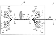
図1は、本実施形態に係るレーザ装置1を示す概念図である。図1に示すように、本実施形態のレーザ装置1は、光源10と光源10から出力する光が入力する光デバイス40とを主な構成として備える。
図1は、本実施形態に係るレーザ装置1を示す概念図である。図1に示すように、本実施形態のレーザ装置1は、光源10と光源10から出力する光が入力する光デバイス40とを主な構成として備える。
図1に示す光源10は、励起光源20a,20bと、光コンバイナ25a,25bと、増幅用光ファイバ26と、第1共振用ファイバ16と、第2共振用ファイバ17と、第1FBG(Fiber Bragg Grating)18と、第2FBG19と、光ファイバ11と、を主な構成として備える。
励起光源20a,20bは、複数のレーザダイオード21とこれらのレーザダイオード21のそれぞれに接続される励起光用ファイバ22とを有する。励起光用ファイバ22としては、例えば、マルチモードファイバが挙げられる。この場合、レーザダイオード21から出力される励起光は、励起光用ファイバ22をマルチモード光として伝搬する。
増幅用光ファイバ26は、励起光源20a,20bから出力される励起光により励起されるイッテルビウム(Yb)等の活性元素を含むコアと、コアを被覆するクラッドと、クラッドを被覆する外側クラッドと、外側クラッドを被覆する被覆層と、から構成される。クラッドの屈折率はコアの屈折率よりも低く、外側クラッドの屈折率はクラッドの屈折率よりもさらに低くされている。
第1共振用ファイバ16は、一方の端部が光コンバイナ25aを介して励起光源20aに接続されると共に他方の端部が増幅用光ファイバ26の一方の端部に接続される。第1共振用ファイバ16としては、例えば、シングルモードファイバが挙げられる。また、第1共振用ファイバ16は、コアとクラッドと外側クラッドとを有するダブルクラッドファイバとされる。このような第1共振用ファイバ16は、例えば、増幅用光ファイバ26と同様の構成でコアに活性元素が添加されない構成とされる。第1共振用ファイバ16のコアは増幅用光ファイバ26のコアと結合し、第1共振用ファイバ16のクラッドは増幅用光ファイバ26のクラッドと結合している。
また、第1共振用ファイバ16のコアには、第1ミラーとしての第1FBG18が設けられている。第1FBG18は、増幅用光ファイバ26のコアに添加されている上記活性元素が励起状態とされた状態で放出する光のうち少なくとも一部の波長の光を反射するように構成されている。第1FBG18の反射率は、後述の第2FBG19の反射率よりも高く、上記活性元素が放出する光のうち所望の波長の光を90%以上で反射することが好ましく、99%以上で反射することがより好ましい。なお、第1FBG18が反射する光の波長は赤外光領域とされ、上記活性元素がイッテルビウムである場合、第1FBG18が反射する光の波長は、例えば1060nmとされる。
光コンバイナ25aは、第1共振用ファイバ16と励起光源20aのそれぞれの励起光用ファイバ22とを接続している。光コンバイナ25aにおいて、励起光用ファイバ22のコアは第1共振用ファイバ16のクラッドと結合している。このため、励起光源20aから出力される励起光は、光コンバイナ25aを介して第1共振用ファイバ16のクラッドに入力される。
第2共振用ファイバ17は、一方の端部が光コンバイナ25bを介して励起光源20bに接続されると共に他方の端部が増幅用光ファイバ26の他方の端部に接続される。第2共振用ファイバ17としては、例えば、シングルモードファイバが挙げられる。また、第2共振用ファイバ17は、コアとクラッドと外側クラッドとを有するダブルクラッドファイバとされる。このような第2共振用ファイバ17は、例えば、コアに活性元素が添加されない以外は増幅用光ファイバ26と同様の構成とされる。第2共振用ファイバ17のコアは、増幅用光ファイバ26のコアと結合し、第2共振用ファイバ17のクラッドは増幅用光ファイバ26のクラッドと結合している。
また、第2共振用ファイバ17のコアには、第2ミラーとしての第2FBG19が設けられている。第2FBG19は、第1FBG18が反射する光のうち少なくとも一部の波長の光を第1FBG18より低い反射率で反射するように構成されている。第2FBG19は、第1FBG18が反射する光が入力する場合に、この光を例えば10%程度の反射率で反射する。
光コンバイナ25bは、第2共振用ファイバ17と励起光源20bのそれぞれの励起光用ファイバ22とを接続している。光コンバイナ25bにおいて、励起光用ファイバ22のコアは第2共振用ファイバ17のクラッドと結合している。このため、励起光源20bから出力される励起光は、光コンバイナ25bを介して第2共振用ファイバ17のクラッドに入力される。
また、第2共振用ファイバ17の増幅用光ファイバ26側と反対側には、光コンバイナ25bを介して光ファイバ11が接続されている。光ファイバ11は、例えば、コアとコアを被覆するクラッドとクラッドを被覆する被覆層とから構成され、コアの直径が20μm程度であって、基本モードの光と例えば1個から5個程度の高次モードの光とを伝搬可能なフューモードファイバとされる。
以上のように、光源10は、励起光源20a,20bと増幅用光ファイバ26と第1FBG18と第2FBG19とを有する共振器を備えている。この光源10は、増幅用光ファイバ26の前方側及び後方側の双方から励起光を入力する双方励起であって、第1FBG18と第2FBG19とで共振を行うファブリペロー型のファイバレーザ装置である。
このような光源10においては、まず、励起光源20a,20bのそれぞれのレーザダイオード21から励起光が出力される。そして、それぞれのレーザダイオード21から出力された励起光は、励起光用ファイバ22及び第1共振用ファイバ16を介して増幅用光ファイバ26の前方側から、又は、励起光用ファイバ22及び第2共振用ファイバ17を介して増幅用光ファイバ26の後方側から、増幅用光ファイバ26のクラッドに入力する。増幅用光ファイバ26のクラッドに入力した励起光は、当該クラッドを主に伝搬する。そして、増幅用光ファイバ26のコアを通過するときに当該コアに添加されている活性元素に吸収されて、活性元素を励起状態にする。
こうして励起光により励起状態とされた活性元素から自然放出光が放出され、この自然放出光を元にして第1FBG18と第2FBG19との間で光の共振が起こる。共振する光は、第1FBG18及び第2FBG19の反射波長と同じ波長であり、この共振する光が、被増幅光として増幅用光ファイバ26において励起された活性元素の誘導放出により増幅される。そして、増幅された光の一部が、第2FBG19を透過して光ファイバ11に入力される。なお、上記のように第1FBG18及び第2FBG19で反射される光の波長は例えば0.80μm~1.25μm程度の赤外光領域とされ、上記のようにして光源10から出力される光は赤外光である。
また、光源10は、赤外光をパルス光と連続光とに切り替えて出力可能である。より具体的には、光源10は、パルス光を後述する第1の閾値以上の強度で出力し、連続光を当該第1の閾値未満の強度で出力するように構成される。
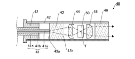
図2は、図1に示す光デバイス40の一部を概略的に示す断面図であり、光ファイバ41の中心軸に平行な断面図である。図2に示すように、光デバイス40は、光ファイバ41、石英ブロック43、集光レンズ44、波長変換素子50、コリメートレンズ45、保護レンズ46、スペーサ42、及び筐体47を主な構成として備える。
光ファイバ41は、上記光ファイバ11の一部または光ファイバ11に接続される他の光ファイバとされる。光ファイバ41は、コア41a、コア41aを囲うクラッド41b、およびクラッド41bを被覆する被覆層41cを有する。光ファイバ41の一方の端部では、被覆層41cが剥がされており、クラッド41bが露出している。また、光ファイバ41の一方の端面は、酸水素バーナ等によって石英ブロック43に融着されている。このような光ファイバ41は、例えば、コア41aの直径が100μm程度、クラッド41bの外径が360μm程度の光ファイバとされる。
石英ブロック43は、光ファイバ41の外径より大きな外径を有する石英から成る柱状体である。石英ブロック43は、例えば、直径8mm程度、長さ23mm程度の石英から成る円柱状体とされる。石英ブロック43は、光ファイバ41の端面が接続される入力面43aおよび光ファイバ41から入力される光が出力される出力面43bを有している。入力面43aは光ファイバ41の端面より大きく、光ファイバ41の端面は入力面43aの中央部に融着される。
集光レンズ44は、石英ブロック43の出力面43bから出力される光を集光するレンズである。集光レンズ44から出力する光は焦点fにおいて集光される。また、コリメートレンズ45は、集光レンズ44を透過した光を平行光とするレンズである。さらに、コリメートレンズ45で平行光とされた光は、保護レンズ46を介して出力される。保護レンズ46は、レーザ装置1の出力端を保護する部材である。
本実施形態において、波長変換素子50は、上記焦点fに重なる位置に配置される。波長変換素子50は、第1の閾値以上の強度の赤外光を可視光に波長変換する。このような波長変換素子50としては、例えば、LiNbO3(LN)、LiTaO3(LT)、KTiOPO4(KTP)などが用いられる。
筐体47は、光ファイバ41の出力端、石英ブロック43、集光レンズ44、波長変換素子50、コリメートレンズ45、及び保護レンズ46を収容する部材である。筐体47は筒状に形成されており、光ファイバ41の一方の端部が挿入される。また、筐体47の一方の端部は、保護レンズ46によって封止されている。また、筐体47の他方の端部は、スペーサ42によって封止されている。スペーサ42は、中心に貫通孔を有しており、当該貫通孔に光ファイバ41が挿通される。
次に、本実施形態のレーザ装置1の動作および作用について説明する。
<レーザ光の照射位置確認時>
光源10から赤外光が出力すると、当該赤外光は、光ファイバ11を伝搬し、光ファイバ11を介して光デバイス40から出力する。光デバイス40において、当該赤外光は波長変換素子50に入力する。
光源10から赤外光が出力すると、当該赤外光は、光ファイバ11を伝搬し、光ファイバ11を介して光デバイス40から出力する。光デバイス40において、当該赤外光は波長変換素子50に入力する。
ここで、光源10は、上記のように、パルス光を第1の閾値以上の強度で出力し、連続光を第1の閾値未満の強度で出力する。また、波長変換素子50は、第1の閾値以上の強度の赤外光を可視光に波長変換する。したがって、レーザ光の照射位置を確認するときは、光源10から第1の閾値以上の強度でパルス光を出力することによって、当該パルス光が波長変換素子50によって可視光に波長変換され、可視光が加工対象物に照射されることによってレーザ光の照射位置を確認することができる。なお、レーザ光の照射位置を確認する際には高強度のレーザ光が出力されることになるが、これはパルス光であるため、照射時間が短く、加工対象物が意図せず加工されることを抑制することができる。
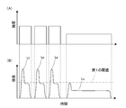
本実施形態では、励起光源20a,20bからの励起光の出力と停止とを繰り返すことによって、上記のように第1の閾値以上のパルス光を光源10から出力することができる。第1の閾値以上のパルス光を光源10から出力する方法について、図3(A)及び図3(B)を参照して以下に詳細に説明する。図3(A)は、励起光の強度と時間との関係の一例を示す図であり、横軸が時間、縦軸が光の強度である。図3(B)は、光源10から出力されるパルス光及び連続光の強度と時間との関係の一例を示す図であり、横軸が時間、縦軸が光の強度である。なお、図3(A)及び図3(B)はそれぞれ概念を示す図であり、光源10から出力される光及び励起光の波形とこれらの光の出力のタイミングとは、実際と異なる場合がある。
図3(A)に示すように励起光の出力と停止とを繰り返すことで、図3(B)に示すように光源10からの光の出力と停止とが繰り返され、パルス光Lpが出力される。また、共振器を有する光源10から光を出力させる場合、図3(B)に示すように最初に強度の高い光が出力され易い。この強度の高い光によって、第1の閾値以上の強度を有するパルス光Lpを形成することができる。このようにして形成されるパルス光のうち第1の閾値以上の強度を有するのは最初の一部のみであるため、第1の閾値以上の強度を有する光のエネルギーが大きくなり過ぎることを抑制することができる。したがって、第1の閾値以上の強度を有する連続光が波長変換素子に入力する場合に比べて、波長変換素子50に入力する光のエネルギーを抑えることが抑制することができ、波長変換素子50の損傷を抑制することができる。なお、図3には第1の閾値を超えるパルス光Lpが複数出力される例が示されているが、第1の閾値を超えるパルス光Lpの数は特に限定されず、1つでも良い。
<レーザ光による加工時>
レーザ光による加工時は、図3(B)に示すように、光源10から第1の閾値未満の強度で連続光Lcを出力することによって、波長変換素子50において、当該連続光が可視光に波長変換されることを抑制することができる。したがって、レーザ光による加工時には可視光への波長変換が抑制された意図した波長の光が加工対象物に照射される。なお、連続光Lcもパルス光Lpと同様に、最初に強度の高い光が出力され易い。この場合、この強度が高い光をパルス光Lpと捉えて、パルス光Lpに続けて連続光が出力していると理解することができる。ただし、この強度が高い光はパルス光Lpと同様に出力される時間が短いため、この強度が高い光がレーザ光による加工に及ぼす影響を抑制することができる。
レーザ光による加工時は、図3(B)に示すように、光源10から第1の閾値未満の強度で連続光Lcを出力することによって、波長変換素子50において、当該連続光が可視光に波長変換されることを抑制することができる。したがって、レーザ光による加工時には可視光への波長変換が抑制された意図した波長の光が加工対象物に照射される。なお、連続光Lcもパルス光Lpと同様に、最初に強度の高い光が出力され易い。この場合、この強度が高い光をパルス光Lpと捉えて、パルス光Lpに続けて連続光が出力していると理解することができる。ただし、この強度が高い光はパルス光Lpと同様に出力される時間が短いため、この強度が高い光がレーザ光による加工に及ぼす影響を抑制することができる。
以上のように、レーザ装置1によれば、可視光によってレーザ光の照射位置を確認する時とレーザ光による加工時とで部材の配置転換等を行う必要がなく、容易にレーザ光の照射位置を確認してからレーザ光による加工を行うことができる。
また、本実施形態のレーザ装置1は、上記のように赤外光を集光する集光レンズ44を備えており、集光レンズ44の焦点fと重なる位置に波長変換素子50が設けられている。このように赤外光が集光される位置に波長変換素子50が設けられることによって、高強度のパルス光を波長変換素子50に入力させ易くなるので、パルス光を波長変換素子50によって可視光に波長変換させることが容易になる。したがって、可視光によってレーザ光の照射位置を確認することがより容易になる。
(第2実施形態)
次に、本発明の第2実施形態について図4を参照して詳細に説明する。なお、第1実施形態と同一又は同等の構成要素については、特に説明する場合を除き、同一の参照符号を付して重複する説明は省略する。
次に、本発明の第2実施形態について図4を参照して詳細に説明する。なお、第1実施形態と同一又は同等の構成要素については、特に説明する場合を除き、同一の参照符号を付して重複する説明は省略する。
図4は、本実施形態に係るレーザ装置2を示す概念図である。図4に示すように、本実施形態のレーザ装置2は、ラマン変換部35を備える点で、上記第1実施形態に係るレーザ装置1と異なる。
ラマン変換部35には、光ファイバ11から出力する光が入力する。ラマン変換部35は、光ファイバから成り、第1の閾値よりも強い第2の閾値以上の強度の光が入力する場合にラマン散乱光を生じるように構成される。また、ラマン変換部35から出力する光は、光デバイス40に入力する。
本実施形態のレーザ装置2では、光源10は、第2の閾値以上の強度を有するパルス光を出力するように構成される。したがって、光源10から出力されるパルス光はラマン変換部35においてラマン散乱光を生じる。一方、光源10から出力される連続光は、第1の閾値未満の強度であるため、第2の閾値未満の強度となる。よって、光源10から出力される連続光からラマン散乱光が生じることを抑制することができる。また、本実施形態の波長変換素子50は、このようにしてパルス光から生じるラマン散乱光を可視光に波長変換する。これらの光の波長と強度との関係を図5に示す。図5は、縦軸が光の強度であり、横軸が光の周波数である。
図5に示すL1は光源10から出力されるパルス光、L2はラマン変換部35においてパルス光L1から生じるラマン散乱光、L3は波長変換素子50でラマン散乱光L2が変換されて生じる可視光、L4は光源10から出力される連続光である。図5に示すように、光源10から出力されるパルス光L1は第2の閾値より高い強度を有しており、パルス光L1の一部はラマン変換部35においてラマン散乱光L2となる。また、ラマン散乱光L2は第1の閾値より高い強度を有しており、ラマン散乱光L2の一部は波長変換素子50において可視光L3に波長変換される。光源10から出力される連続光L4は第1の閾値及び第2の閾値より小さな強度を有しており、ラマン変換部35及び波長変換素子50において連続光L4からは波長の異なる光を生じることが抑制される。
波長変換素子50は、一般的に、波長変換し易い波長を有する。したがって、上記のようにラマン散乱光を可視光に波長変換する波長変換素子50を用いる場合、ラマン散乱光とは波長が異なるパルス光や連続光が波長変換素子50によって波長変換されることを抑制することができる。このため、レーザ光による加工時には加工に必要な意図した波長の光を出力することができる。また、波長変換素子50によってラマン散乱光とは波長が異なる連続光が波長変換されることを抑制できることによって、レーザ光による加工時に波長変換素子50における光のロスを抑制することができる。ただし、波長変換素子50の種類によっては、上記パルス光L1のうち第1の閾値を超える強度を有する光が波長変換素子50によって波長変換される場合がある。この場合、パルス光L1の一部が可視光L3よりも波長が小さな可視光もしくは紫外光に変換される。
本実施形態の波長変換素子50としては、例えば、光源10から出力される赤外光の波長を1000~1100nmとし、光源10から出力されるパルス光からラマン変換部35において生じるラマン散乱光の波長を1050~1150nmとする場合、LiNbO3(LN)、LiTaO3(LT)、KTiOPO4(KTP)などが用いられる。
以上、本発明について、第1、第2実施形態を例に説明したが、本発明はこれらに限定されるものではない。
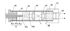
上記実施形態では、集光レンズ44の焦点fに重なる位置に波長変換素子50が設けられる例を挙げて説明した。しかし、本発明は当該実施形態に限定されず、レーザ装置から出力される赤外光が波長変換素子50を介して加工対象物に照射されるように、波長変換素子50が配置されれば良い。例えば、石英ブロック43と集光レンズ44との間に波長変換素子50が設けられても良く、コリメートレンズ45と保護レンズ46との間に波長変換素子50が設けられても良い。これらのように波長変換素子50が設けられる場合は、焦点fに重なる位置に設けられる場合に比べて波長変換素子50に入力する光のエネルギー密度が低くなるため、波長変換素子50の破損を抑制し易くなる。さらに、波長変換素子50は、図6に示すように筐体47の外側に設けられても良い。図6は変形例に係るレーザ装置の出力端を図2と同じ視点で示す断面図である。図6において、図2と同一又は同等の構成要素については同一の参照符号を付して重複する説明は省略する。図6に示す例では、筐体47の外側において、赤外光が照射される位置に取付マウント51によって波長変換素子50が設けられる。このように波長変換素子50が筐体47の外側に設けられることによって、波長変換素子50の取り外しが容易になるため、メンテナンス等が容易になる。
また、上記実施形態では、励起光源20a,20bからの励起光の出力と停止とを繰り返すことでパルス光を出力する方法を例示したが、本発明は係る形態に限定されない。例えば、光源10からパルス光を出力するときは連続光を出力するときよりも励起光源20a,20bから出力される励起光の強度が高くされることによっても、上記のように第1の閾値以上のパルス光を出力することができる。図7(A)及び図7(B)を参照して以下に詳細に説明する。図7(A)は、励起光の強度と時間との関係の他の例を示す図であり、横軸が時間、縦軸が光の強度である。図7(B)は、光源10から出力されるパルス光及び連続光の強度と時間との関係の他の例を示す図であり、横軸が時間、縦軸が光の強度である。なお、図7(A)及び図7(B)はそれぞれ概念を示す図であり、光源10から出力される光及び励起光の波形とこれらの光の出力のタイミングとは、実際と異なる場合がある。
図7(A)に示すように励起光源20a,20bから出力される励起光の強度が高くされることによって、図7(B)に示すように光源10から出力される光の強度を高めやすくなる。したがって、パルス光Lpを出力するときに連続光Lcを出力するときよりも励起光の強度が高くされることによって、パルス光Lpの強度と連続光Lcの強度とに差をつけやすくなる。このため、パルス光Lpを波長変換素子50によって可視光に波長変換すると共に連続光Lcの可視光への波長変換を抑制することが容易になる。
また、Qスイッチを設け、当該Qスイッチによって第1の閾値以上のパルス光と第1の閾値未満の連続光とが出力されるようにすることもできる。
また、これまでの説明では、パルス光が間隔を開けて出力される例を挙げて説明したが、パルス光の間隔が狭められる、またはパルス光が重なるように光源10から出力されても良い。例えば、複数の励起光源20a,20bのうち一部の励起光源と他の一部の励起光源とが交互に励起光を出力することによって、光源10から出力されるパルス光の出力間隔を小さくすることができる。この例として、励起光源20aと励起光源20bとが交互に励起光を出力することが挙げられる。このように複数の励起光源から交互に励起光を出力させることによって、光源10から出力されるパルス光が波長変換素子50において波長変換されることによって生じる可視光のちらつきを抑制することができ、可視光によってレーザ光の照射位置を確認することがより容易になる。
また、上記実施形態では、一つの光源10を備える形態を例示して説明したが、光源の数は特に限定されず、光源は複数であっても良い。また、光源は固体レーザ等であっても良い。
以上説明したように、本発明によれば、レーザ光の照射位置を確認してからレーザ光による加工を行うことが容易なレーザ装置が提供され、レーザを用いる加工方法等の分野で利用することが期待される。
1,2・・・レーザ装置
10・・・光源
11・・・光ファイバ
18・・・第1FBG
19・・・第2FBG
20a,20b・・・励起光源
21・・・レーザダイオード
22・・・励起光用ファイバ
26・・・増幅用光ファイバ
35・・・ラマン変換部
44・・・集光レンズ
47・・・筐体
50・・・波長変換素子
Lp・・・パルス光
Lc・・・連続光
10・・・光源
11・・・光ファイバ
18・・・第1FBG
19・・・第2FBG
20a,20b・・・励起光源
21・・・レーザダイオード
22・・・励起光用ファイバ
26・・・増幅用光ファイバ
35・・・ラマン変換部
44・・・集光レンズ
47・・・筐体
50・・・波長変換素子
Lp・・・パルス光
Lc・・・連続光
Claims (8)
- 赤外光をパルス光と連続光とに切り替えて出力可能な光源と、
前記赤外光が入力し、第1の閾値以上の強度の前記赤外光を可視光に波長変換する波長変換素子と、
を備え、
前記光源は、前記パルス光の少なくとも一部を前記第1の閾値以上の強度で出力し、前記連続光を前記第1の閾値未満の強度で出力する
ことを特徴とするレーザ装置。 - 前記第1の閾値よりも強い第2の閾値以上の強度の光からラマン散乱光を生じさせるラマン変換部を備え、
前記光源は、前記パルス光の少なくとも一部を前記第2の閾値以上の強度で出力し、
前記波長変換素子は、前記ラマン変換部において前記パルス光から生じる前記ラマン散乱光を可視光に波長変換する
ことを特徴とする請求項1に記載のレーザ装置。 - 前記光源は、
励起光を出力する励起光源と、
前記励起光により励起される活性元素がコアに添加されている増幅用光ファイバと、
前記増幅用光ファイバの一方側に設けられ、励起状態とされた前記活性元素が放出する光の少なくとも一部の波長の光を反射する第1ミラーと、
前記増幅用光ファイバの他方側に設けられ、前記第1ミラーが反射する光のうち少なくとも一部の波長の光を前記第1ミラーより低い反射率で反射する第2ミラーと、
を有する共振器を備える
ことを特徴とする請求項1または2に記載のレーザ装置。 - 前記パルス光を出力するときに前記連続光を出力するときよりも前記励起光の強度が高くされる
ことを特徴とする請求項3に記載のレーザ装置。 - 前記励起光の出力と停止とを繰り返すことで前記パルス光を出力する
ことを特徴とする請求項3または4に記載のレーザ装置。 - 前記励起光源を複数備え、
一部の前記励起光源と他の一部の前記励起光源とが交互に前記励起光を出力する
ことを特徴とする請求項3から5のいずれか1項に記載のレーザ装置。 - 前記赤外光を伝搬する光ファイバと、
前記光ファイバの出力端に接続される石英ブロックと、
前記石英ブロックから出力する前記赤外光を集光する集光レンズと、
を備え、
前記集光レンズの焦点と重なる位置に前記波長変換素子が設けられる
ことを特徴とする請求項1から6のいずれか1項に記載のレーザ装置。 - 前記赤外光を伝搬する光ファイバと、
前記光ファイバの出力端に接続される石英ブロックと、
前記光ファイバの出力端及び前記石英ブロックを収納する筐体と、
を備え、
前記筐体の外側において、前記赤外光が照射される位置に前記波長変換素子が設けられる
ことを特徴とする請求項1から6のいずれか1項に記載のレーザ装置。
Priority Applications (3)
| Application Number | Priority Date | Filing Date | Title |
|---|---|---|---|
| EP17860251.2A EP3528352A4 (en) | 2016-10-11 | 2017-10-11 | LASER DEVICE |
| CN201780062419.1A CN109804512B (zh) | 2016-10-11 | 2017-10-11 | 激光装置 |
| US16/341,006 US20190314928A1 (en) | 2016-10-11 | 2017-10-11 | Laser device |
Applications Claiming Priority (2)
| Application Number | Priority Date | Filing Date | Title |
|---|---|---|---|
| JP2016200359A JP6807699B2 (ja) | 2016-10-11 | 2016-10-11 | レーザ装置 |
| JP2016-200359 | 2016-10-11 |
Publications (1)
| Publication Number | Publication Date |
|---|---|
| WO2018070412A1 true WO2018070412A1 (ja) | 2018-04-19 |
Family
ID=61906384
Family Applications (1)
| Application Number | Title | Priority Date | Filing Date |
|---|---|---|---|
| PCT/JP2017/036795 Ceased WO2018070412A1 (ja) | 2016-10-11 | 2017-10-11 | レーザ装置 |
Country Status (5)
| Country | Link |
|---|---|
| US (1) | US20190314928A1 (ja) |
| EP (1) | EP3528352A4 (ja) |
| JP (1) | JP6807699B2 (ja) |
| CN (1) | CN109804512B (ja) |
| WO (1) | WO2018070412A1 (ja) |
Cited By (1)
| Publication number | Priority date | Publication date | Assignee | Title |
|---|---|---|---|---|
| JPWO2021210267A1 (ja) * | 2020-04-15 | 2021-10-21 |
Families Citing this family (3)
| Publication number | Priority date | Publication date | Assignee | Title |
|---|---|---|---|---|
| CN110350392B (zh) * | 2019-08-02 | 2021-01-19 | 华中科技大学鄂州工业技术研究院 | 基于受激布里渊散射的连续和脉冲可切换的装置、方法 |
| JP7407964B2 (ja) * | 2020-09-25 | 2024-01-04 | 古河電気工業株式会社 | レーザ加工方法およびレーザ加工装置 |
| CN115415676A (zh) * | 2022-09-27 | 2022-12-02 | 峰米(重庆)创新科技有限公司 | 激光雕刻设备 |
Citations (9)
| Publication number | Priority date | Publication date | Assignee | Title |
|---|---|---|---|---|
| JP2001350166A (ja) | 2000-06-09 | 2001-12-21 | Ishikawajima Harima Heavy Ind Co Ltd | 不可視波長領域レーザ光の光軸位置調整方法 |
| JP2004288840A (ja) * | 2003-03-20 | 2004-10-14 | Fujikura Ltd | 赤外光レーザー光源 |
| US20110058250A1 (en) * | 2008-08-21 | 2011-03-10 | Nlight Photonics Corporation | High power fiber amplifier with stable output |
| JP2011100954A (ja) * | 2009-11-09 | 2011-05-19 | Fujikura Ltd | ファイバレーザ装置 |
| JP2012156175A (ja) * | 2011-01-24 | 2012-08-16 | Panasonic Corp | ファイバレーザ光源装置およびそれを用いた波長変換レーザ光源装置 |
| JP2013102007A (ja) * | 2011-11-08 | 2013-05-23 | Furukawa Electric Co Ltd:The | ファイバレーザ装置 |
| JP2014085519A (ja) * | 2012-10-24 | 2014-05-12 | Citizen Holdings Co Ltd | レーザ光源装置およびレーザ光源装置を用いたレーザ・プロジェクタ |
| JP2015507348A (ja) * | 2011-11-09 | 2015-03-05 | マッコーリー ユニバーシティー | 波長可変型のvecselラマンレーザ |
| JP2015126036A (ja) * | 2013-12-25 | 2015-07-06 | 古河電気工業株式会社 | 光ファイバレーザ装置の制御方法および光ファイバレーザ装置 |
Family Cites Families (5)
| Publication number | Priority date | Publication date | Assignee | Title |
|---|---|---|---|---|
| JP5662770B2 (ja) * | 2010-11-25 | 2015-02-04 | 株式会社フジクラ | ファイバレーザ装置 |
| WO2012148062A1 (ko) * | 2011-04-28 | 2012-11-01 | 광주과학기술원 | 펄스 레이저 장치 및 이를 이용한 버스트 모드, 가변 버스트 모드 제어 방법 |
| WO2013111271A1 (ja) * | 2012-01-24 | 2013-08-01 | 株式会社フジクラ | ファイバレーザ装置 |
| WO2016044395A1 (en) * | 2014-09-16 | 2016-03-24 | Ipg Photonics Corporation | Broadband red light generator for rgb display |
| CN105527679B (zh) * | 2015-12-29 | 2017-11-28 | 孟祥宇 | 一种光纤激光输出头及其制造方法 |
-
2016
- 2016-10-11 JP JP2016200359A patent/JP6807699B2/ja active Active
-
2017
- 2017-10-11 EP EP17860251.2A patent/EP3528352A4/en not_active Withdrawn
- 2017-10-11 US US16/341,006 patent/US20190314928A1/en not_active Abandoned
- 2017-10-11 CN CN201780062419.1A patent/CN109804512B/zh not_active Expired - Fee Related
- 2017-10-11 WO PCT/JP2017/036795 patent/WO2018070412A1/ja not_active Ceased
Patent Citations (9)
| Publication number | Priority date | Publication date | Assignee | Title |
|---|---|---|---|---|
| JP2001350166A (ja) | 2000-06-09 | 2001-12-21 | Ishikawajima Harima Heavy Ind Co Ltd | 不可視波長領域レーザ光の光軸位置調整方法 |
| JP2004288840A (ja) * | 2003-03-20 | 2004-10-14 | Fujikura Ltd | 赤外光レーザー光源 |
| US20110058250A1 (en) * | 2008-08-21 | 2011-03-10 | Nlight Photonics Corporation | High power fiber amplifier with stable output |
| JP2011100954A (ja) * | 2009-11-09 | 2011-05-19 | Fujikura Ltd | ファイバレーザ装置 |
| JP2012156175A (ja) * | 2011-01-24 | 2012-08-16 | Panasonic Corp | ファイバレーザ光源装置およびそれを用いた波長変換レーザ光源装置 |
| JP2013102007A (ja) * | 2011-11-08 | 2013-05-23 | Furukawa Electric Co Ltd:The | ファイバレーザ装置 |
| JP2015507348A (ja) * | 2011-11-09 | 2015-03-05 | マッコーリー ユニバーシティー | 波長可変型のvecselラマンレーザ |
| JP2014085519A (ja) * | 2012-10-24 | 2014-05-12 | Citizen Holdings Co Ltd | レーザ光源装置およびレーザ光源装置を用いたレーザ・プロジェクタ |
| JP2015126036A (ja) * | 2013-12-25 | 2015-07-06 | 古河電気工業株式会社 | 光ファイバレーザ装置の制御方法および光ファイバレーザ装置 |
Non-Patent Citations (1)
| Title |
|---|
| See also references of EP3528352A4 * |
Cited By (4)
| Publication number | Priority date | Publication date | Assignee | Title |
|---|---|---|---|---|
| JPWO2021210267A1 (ja) * | 2020-04-15 | 2021-10-21 | ||
| WO2021210267A1 (ja) * | 2020-04-15 | 2021-10-21 | 株式会社フジクラ | 光デバイス及びファイバレーザ装置 |
| JP7284869B2 (ja) | 2020-04-15 | 2023-05-31 | 株式会社フジクラ | 光デバイス及びファイバレーザ装置 |
| US12438330B2 (en) | 2020-04-15 | 2025-10-07 | Fujikura Ltd. | Optical device and fiber laser apparatus |
Also Published As
| Publication number | Publication date |
|---|---|
| JP6807699B2 (ja) | 2021-01-06 |
| CN109804512A (zh) | 2019-05-24 |
| EP3528352A1 (en) | 2019-08-21 |
| JP2018064004A (ja) | 2018-04-19 |
| EP3528352A4 (en) | 2020-07-01 |
| CN109804512B (zh) | 2021-03-30 |
| US20190314928A1 (en) | 2019-10-17 |
Similar Documents
| Publication | Publication Date | Title |
|---|---|---|
| CN109804512B (zh) | 激光装置 | |
| JP2017502531A (ja) | 連続波方式および疑似連続波方式で動作する超高出力の単一モード緑色ファイバレーザ | |
| CN111244735B (zh) | 一种环形窄带光纤光栅随机激光器及产生随机激光的方法 | |
| JP2011023532A (ja) | 光増幅器、レーザ装置及び光源装置 | |
| WO2013111271A1 (ja) | ファイバレーザ装置 | |
| JP6026885B2 (ja) | ドープされたファイバを実装する光源、当該光源用ファイバ、および、当該ファイバの製造方法 | |
| US8194310B1 (en) | All fiber pulse generator for pumping a non-linear converter | |
| JP2011114061A (ja) | レーザ発振器、及び、モードフィルタ | |
| JPH07231131A (ja) | 光ファイバレ−ザ装置 | |
| JP5390907B2 (ja) | カスケードラマン共振器および光ファイバレーザ | |
| JP3905479B2 (ja) | ファイバレーザ装置 | |
| JP4708109B2 (ja) | ファイバレーザ装置 | |
| JP5662770B2 (ja) | ファイバレーザ装置 | |
| US8928971B2 (en) | High-power optical fibre laser | |
| JP6628777B2 (ja) | 反射鏡、ファイバ共振器、およびファイバレーザ | |
| JP2001024264A (ja) | 波長変換レーザ装置 | |
| JP2012156175A (ja) | ファイバレーザ光源装置およびそれを用いた波長変換レーザ光源装置 | |
| JP2010278289A (ja) | レーザ発振装置 | |
| JP2005175171A (ja) | Qスイッチ光ファイバレーザ | |
| JP2005294570A (ja) | 光ファイバ増幅装置、第二次高調波発生装置、光生成方法及び第二次高調波発生方法 | |
| JP2010177314A (ja) | ダブルクラッドファイバ、ファイバレーザ装置及び光増幅器 | |
| JP2018174206A (ja) | レーザ装置 | |
| KR100704603B1 (ko) | 가시광선 광섬유레이저 | |
| JP2008258323A (ja) | パルスレーザ装置 | |
| JP2019029421A (ja) | ファイバレーザ装置 |
Legal Events
| Date | Code | Title | Description |
|---|---|---|---|
| 121 | Ep: the epo has been informed by wipo that ep was designated in this application |
Ref document number: 17860251 Country of ref document: EP Kind code of ref document: A1 |
|
| NENP | Non-entry into the national phase |
Ref country code: DE |
|
| ENP | Entry into the national phase |
Ref document number: 2017860251 Country of ref document: EP Effective date: 20190513 |