WO2018072100A1 - 一种护翼型角钢板以及骨干固定系统 - Google Patents
一种护翼型角钢板以及骨干固定系统 Download PDFInfo
- Publication number
- WO2018072100A1 WO2018072100A1 PCT/CN2016/102447 CN2016102447W WO2018072100A1 WO 2018072100 A1 WO2018072100 A1 WO 2018072100A1 CN 2016102447 W CN2016102447 W CN 2016102447W WO 2018072100 A1 WO2018072100 A1 WO 2018072100A1
- Authority
- WO
- WIPO (PCT)
- Prior art keywords
- locking
- backbone
- steel plate
- angle steel
- wing
- Prior art date
- Legal status (The legal status is an assumption and is not a legal conclusion. Google has not performed a legal analysis and makes no representation as to the accuracy of the status listed.)
- Ceased
Links
Images




Classifications
-
- A—HUMAN NECESSITIES
- A61—MEDICAL OR VETERINARY SCIENCE; HYGIENE
- A61B—DIAGNOSIS; SURGERY; IDENTIFICATION
- A61B17/00—Surgical instruments, devices or methods
- A61B17/56—Surgical instruments or methods for treatment of bones or joints; Devices specially adapted therefor
- A61B17/58—Surgical instruments or methods for treatment of bones or joints; Devices specially adapted therefor for osteosynthesis, e.g. bone plates, screws or setting implements
- A61B17/68—Internal fixation devices, including fasteners and spinal fixators, even if a part thereof projects from the skin
- A61B17/80—Cortical plates, i.e. bone plates; Instruments for holding or positioning cortical plates, or for compressing bones attached to cortical plates
- A61B17/8004—Cortical plates, i.e. bone plates; Instruments for holding or positioning cortical plates, or for compressing bones attached to cortical plates with means for distracting or compressing the bone or bones
-
- A—HUMAN NECESSITIES
- A61—MEDICAL OR VETERINARY SCIENCE; HYGIENE
- A61B—DIAGNOSIS; SURGERY; IDENTIFICATION
- A61B17/00—Surgical instruments, devices or methods
- A61B17/56—Surgical instruments or methods for treatment of bones or joints; Devices specially adapted therefor
-
- A—HUMAN NECESSITIES
- A61—MEDICAL OR VETERINARY SCIENCE; HYGIENE
- A61B—DIAGNOSIS; SURGERY; IDENTIFICATION
- A61B17/00—Surgical instruments, devices or methods
- A61B17/56—Surgical instruments or methods for treatment of bones or joints; Devices specially adapted therefor
- A61B17/58—Surgical instruments or methods for treatment of bones or joints; Devices specially adapted therefor for osteosynthesis, e.g. bone plates, screws or setting implements
-
- A—HUMAN NECESSITIES
- A61—MEDICAL OR VETERINARY SCIENCE; HYGIENE
- A61B—DIAGNOSIS; SURGERY; IDENTIFICATION
- A61B17/00—Surgical instruments, devices or methods
- A61B17/56—Surgical instruments or methods for treatment of bones or joints; Devices specially adapted therefor
- A61B17/58—Surgical instruments or methods for treatment of bones or joints; Devices specially adapted therefor for osteosynthesis, e.g. bone plates, screws or setting implements
- A61B17/68—Internal fixation devices, including fasteners and spinal fixators, even if a part thereof projects from the skin
- A61B17/80—Cortical plates, i.e. bone plates; Instruments for holding or positioning cortical plates, or for compressing bones attached to cortical plates
- A61B17/8004—Cortical plates, i.e. bone plates; Instruments for holding or positioning cortical plates, or for compressing bones attached to cortical plates with means for distracting or compressing the bone or bones
- A61B17/8014—Cortical plates, i.e. bone plates; Instruments for holding or positioning cortical plates, or for compressing bones attached to cortical plates with means for distracting or compressing the bone or bones the extension or compression force being caused by interaction of the plate hole and the screws
-
- A—HUMAN NECESSITIES
- A61—MEDICAL OR VETERINARY SCIENCE; HYGIENE
- A61B—DIAGNOSIS; SURGERY; IDENTIFICATION
- A61B17/00—Surgical instruments, devices or methods
- A61B17/56—Surgical instruments or methods for treatment of bones or joints; Devices specially adapted therefor
- A61B17/58—Surgical instruments or methods for treatment of bones or joints; Devices specially adapted therefor for osteosynthesis, e.g. bone plates, screws or setting implements
- A61B17/68—Internal fixation devices, including fasteners and spinal fixators, even if a part thereof projects from the skin
- A61B17/80—Cortical plates, i.e. bone plates; Instruments for holding or positioning cortical plates, or for compressing bones attached to cortical plates
- A61B17/8052—Cortical plates, i.e. bone plates; Instruments for holding or positioning cortical plates, or for compressing bones attached to cortical plates immobilised relative to screws by interlocking form of the heads and plate holes, e.g. conical or threaded
-
- A—HUMAN NECESSITIES
- A61—MEDICAL OR VETERINARY SCIENCE; HYGIENE
- A61B—DIAGNOSIS; SURGERY; IDENTIFICATION
- A61B17/00—Surgical instruments, devices or methods
- A61B17/56—Surgical instruments or methods for treatment of bones or joints; Devices specially adapted therefor
- A61B17/58—Surgical instruments or methods for treatment of bones or joints; Devices specially adapted therefor for osteosynthesis, e.g. bone plates, screws or setting implements
- A61B17/68—Internal fixation devices, including fasteners and spinal fixators, even if a part thereof projects from the skin
- A61B17/84—Fasteners therefor or fasteners being internal fixation devices
- A61B17/86—Pins or screws or threaded wires; nuts therefor
- A61B17/8605—Heads, i.e. proximal ends projecting from bone
- A61B17/861—Heads, i.e. proximal ends projecting from bone specially shaped for gripping driver
- A61B17/8615—Heads, i.e. proximal ends projecting from bone specially shaped for gripping driver at the central region of the screw head
-
- A—HUMAN NECESSITIES
- A61—MEDICAL OR VETERINARY SCIENCE; HYGIENE
- A61B—DIAGNOSIS; SURGERY; IDENTIFICATION
- A61B17/00—Surgical instruments, devices or methods
- A61B17/56—Surgical instruments or methods for treatment of bones or joints; Devices specially adapted therefor
- A61B17/58—Surgical instruments or methods for treatment of bones or joints; Devices specially adapted therefor for osteosynthesis, e.g. bone plates, screws or setting implements
- A61B17/68—Internal fixation devices, including fasteners and spinal fixators, even if a part thereof projects from the skin
- A61B17/84—Fasteners therefor or fasteners being internal fixation devices
- A61B17/86—Pins or screws or threaded wires; nuts therefor
- A61B17/8625—Shanks, i.e. parts contacting bone tissue
-
- A—HUMAN NECESSITIES
- A61—MEDICAL OR VETERINARY SCIENCE; HYGIENE
- A61B—DIAGNOSIS; SURGERY; IDENTIFICATION
- A61B17/00—Surgical instruments, devices or methods
- A61B17/56—Surgical instruments or methods for treatment of bones or joints; Devices specially adapted therefor
- A61B17/58—Surgical instruments or methods for treatment of bones or joints; Devices specially adapted therefor for osteosynthesis, e.g. bone plates, screws or setting implements
- A61B17/68—Internal fixation devices, including fasteners and spinal fixators, even if a part thereof projects from the skin
- A61B17/84—Fasteners therefor or fasteners being internal fixation devices
- A61B17/86—Pins or screws or threaded wires; nuts therefor
- A61B17/864—Pins or screws or threaded wires; nuts therefor hollow, e.g. with socket or cannulated
-
- A—HUMAN NECESSITIES
- A61—MEDICAL OR VETERINARY SCIENCE; HYGIENE
- A61B—DIAGNOSIS; SURGERY; IDENTIFICATION
- A61B17/00—Surgical instruments, devices or methods
- A61B17/56—Surgical instruments or methods for treatment of bones or joints; Devices specially adapted therefor
- A61B17/58—Surgical instruments or methods for treatment of bones or joints; Devices specially adapted therefor for osteosynthesis, e.g. bone plates, screws or setting implements
- A61B17/68—Internal fixation devices, including fasteners and spinal fixators, even if a part thereof projects from the skin
- A61B17/80—Cortical plates, i.e. bone plates; Instruments for holding or positioning cortical plates, or for compressing bones attached to cortical plates
- A61B17/8052—Cortical plates, i.e. bone plates; Instruments for holding or positioning cortical plates, or for compressing bones attached to cortical plates immobilised relative to screws by interlocking form of the heads and plate holes, e.g. conical or threaded
- A61B17/8057—Cortical plates, i.e. bone plates; Instruments for holding or positioning cortical plates, or for compressing bones attached to cortical plates immobilised relative to screws by interlocking form of the heads and plate holes, e.g. conical or threaded the interlocking form comprising a thread
-
- A—HUMAN NECESSITIES
- A61—MEDICAL OR VETERINARY SCIENCE; HYGIENE
- A61B—DIAGNOSIS; SURGERY; IDENTIFICATION
- A61B17/00—Surgical instruments, devices or methods
- A61B17/56—Surgical instruments or methods for treatment of bones or joints; Devices specially adapted therefor
- A61B17/58—Surgical instruments or methods for treatment of bones or joints; Devices specially adapted therefor for osteosynthesis, e.g. bone plates, screws or setting implements
- A61B17/68—Internal fixation devices, including fasteners and spinal fixators, even if a part thereof projects from the skin
- A61B17/80—Cortical plates, i.e. bone plates; Instruments for holding or positioning cortical plates, or for compressing bones attached to cortical plates
- A61B17/8061—Cortical plates, i.e. bone plates; Instruments for holding or positioning cortical plates, or for compressing bones attached to cortical plates specially adapted for particular bones
-
- A—HUMAN NECESSITIES
- A61—MEDICAL OR VETERINARY SCIENCE; HYGIENE
- A61B—DIAGNOSIS; SURGERY; IDENTIFICATION
- A61B17/00—Surgical instruments, devices or methods
- A61B17/56—Surgical instruments or methods for treatment of bones or joints; Devices specially adapted therefor
- A61B17/58—Surgical instruments or methods for treatment of bones or joints; Devices specially adapted therefor for osteosynthesis, e.g. bone plates, screws or setting implements
- A61B17/68—Internal fixation devices, including fasteners and spinal fixators, even if a part thereof projects from the skin
- A61B17/80—Cortical plates, i.e. bone plates; Instruments for holding or positioning cortical plates, or for compressing bones attached to cortical plates
- A61B17/809—Cortical plates, i.e. bone plates; Instruments for holding or positioning cortical plates, or for compressing bones attached to cortical plates with bone-penetrating elements, e.g. blades or prongs
-
- A—HUMAN NECESSITIES
- A61—MEDICAL OR VETERINARY SCIENCE; HYGIENE
- A61B—DIAGNOSIS; SURGERY; IDENTIFICATION
- A61B17/00—Surgical instruments, devices or methods
- A61B2017/00526—Methods of manufacturing
Definitions
- the invention relates to the technical field of medical instruments, in particular to a wing-shaped angle steel plate and a bone fixation system for nonunion or fracture nonunion after a bone fracture.
- the stability of the fracture end can be basically divided into two categories of stability and instability.
- stable fractures it is usually repaired by hand, using external fixation such as plaster, splint, brace, traction brake to maintain stable fixation and final healing.
- external fixation such as plaster, splint, brace, traction brake to maintain stable fixation and final healing.
- unstable fixation surgical treatment is needed, including internal fixation system and The external fixation system, wherein the internal fixation system is further divided into a nail plate fixation system and an intramedullary nail fixation system.
- the invention is directed to the problem of instability of the fracture end, non-union of the fracture or delayed healing after the fixation of the bone fracture in the prior art by using the nail plate system, and a wing-shaped angle steel plate structure is proposed, which is connected and matched with each other.
- the matching flap part and the body fixing part which are closely attached to the backbone can stably fix the fracture end and support the fracture end of the backbone fracture from the inner side, prevent the fracture end from being dislocated, and assist the accurate positioning, reduction and healing of the fracture site.
- the invention also relates to a backbone fixation system.
- a wing-shaped angle steel plate comprising: a fitting wing portion and a body fixing portion, the bonding wing portion and the body
- the body fixing portions are fixedly connected to each other, and the fitting wing portions are configured to support the fracture end and have a structure matching the inner side surface of the backbone
- the body fixing portion is configured to fix the fitting wing portion and has a front side with the backbone a matching structure
- the body fixing portion is provided with at least two first locking holes for passing through the first locking screw at a position at the boundary with the fitting wing portion, the angle of the first locking hole Passing the first locking screw to ensure that the body fixing portion and the fitting wing portion are in close contact with the backbone and supporting the inner side of the backbone
- the body fixing portion is provided with at least two structures on the structure matching the front side of the backbone
- a second locking hole passing through the second locking screw the second locking hole being angled such that the passing second locking screw achieves the body fixing portion in close contact with the backbone and controls the rotation and axial stability
- the fitting flap portion has a structure that completely covers the broken end of the fracture.
- the abutment flap has a structure that exposes the fracture end and supports the fracture end at the distal end and the proximal end of the fracture end, respectively.
- the fitting wing portion and the body fixing portion are fabricated by an integral molding process.
- the body fixing portion is further provided with at least two lateral pressing holes for passing through the pressing screw on the structure matching the front side of the backbone, the angle of the lateral pressing hole is such that the pressing screw passes through Pressure is generated between the backbone and the wing-shaped angle plate.
- the body fixing portion has three second locking holes disposed on the structure matching the front side of the backbone, and the three second locking holes are arranged in a line or in a triangle.
- the body fixing portion has four or more second locking holes disposed on the structure matching the front side of the backbone, and four or more second locking holes are arranged in a line or in a polygonal shape.
- a backbone fixing system comprising the above-mentioned wing type angle steel plate, further comprising a first locking screw for fixing the wing angle steel plate through the first locking hole and a second through the second locking hole a locking screw and a backbone outer locking structure for fixing the fracture end, the backbone outer locking structure comprising a locking plate and at least two third locking screws for fixing the locking plate, the locking plate having a matching outer side of the backbone
- the locking plate is provided with at least two third locking holes for passing through the third locking screw on the structure matching the outer side surface of the backbone, and the third locking screw passes through the locking plate Three locking holes.
- the first locking screw and the second locking screw for fixing the wing angle steel plate have a diameter ranging from 2.4 to 4.5 mm.
- the first locking screw and/or the second locking screw and/or the third locking screw are hollow locking screws or solid locking screws.
- the invention relates to a wing-shaped angle steel plate, comprising a fitting wing part and a body fixing part, wherein the bonding wing part and the body fixing part are fixedly connected to each other and preferably integrally formed integrally, and the fitting wing part is used for supporting
- the fracture end has a structure matching the inner side of the backbone
- the body fixing portion is configured to fix the fitting wing portion and has a structure matching the front side of the backbone
- the fixing portion is provided with at least two first locking holes for passing through the first locking screw at a portion at the boundary with the fitting wing portion and at least two are provided on the structure matching the front side of the backbone
- the first locking hole and the second locking hole each have respective specific angles to achieve a specific function in cooperation with the first locking screw and the second locking screw, respectively.
- the wing-type angle steel plate proposed by the invention has the joint wing portion and the body fixing portion connected to each other and cooperated to fix and support the broken end portion of the bone fracture, thereby enhancing the stability of the fracture end and effectively ensuring the stable reduction of the auxiliary fracture site.
- the specific structure of the fitting wing portion and the body fixing portion cooperate with the first locking hole at a specific angle, so that the body fixing portion and the sticker can be realized after the first locking screw is inserted in the direction of the first locking hole
- the protective wing is in close contact with the backbone (ie, the wing-shaped angle steel plate closely fits the backbone) and supports the inner support of the backbone; and the second locking hole is provided at a specific angle so that the second locking screw follows the second locking hole
- the body fixing portion can be in close contact with the backbone and the rotation and axial stability of the body fixing portion can be controlled; and in actual use, the first part can be minimally invasively placed on the front side of the backbone and used to fix the wing-shaped angle steel plate.
- the insertion of the first and second locking screws can be prevented from being interfered with by the original fixing, in particular, the structure of the fitting wing portion is ingenious, which solves the problem that the prior art cannot be minimally invasive on the inner side of the backbone.
- the problem is still in the anterior incision of the diaphysis, but the fitted flap portion can extend into the inner side of the backbone to support the fracture end and can be placed at a specific angle through the first locking hole to enable it to cooperate with the first locking screw.
- the inner support of the backbone is realized to further enhance the reliability of the fixation after the reduction, thereby facilitating fracture healing.
- the fitting wing portion may preferably adopt a structure having a fitting wing portion that completely covers the fracture end, or may have a shape that exposes the fracture end and is at the fracture end.
- the end and the proximal end respectively support the structure of the conforming wing portion of the fracture end, and the specific shape structure can be reasonably selected according to the fracture site, so as to achieve support, stabilize the fracture end, or cover the fracture end portion. Or the fracture end portion is exposed, and the fracture end portion is matched to accelerate the fracture healing and make the fracture healing state better.
- the invention also relates to a backbone fixing system, comprising the above-mentioned wing-shaped angle steel plate, a first locking screw and a second locking screw, and a backbone outer locking structure, the above components are used together, and the wing-shaped angle steel plate realizes effective fracture
- the end part supports and fixes and close contact with the backbone.
- the outer locking structure of the backbone uses the locking plate to achieve accurate positioning and fixation of the bone fracture site, further strengthens the effective support and fixation for the bone fracture, and assists the accurate positioning of the fracture site, effectively protecting The stability of the bone fracture after reduction.
- Figure 1 is a schematic diagram of bone nonunion after a bone fracture.
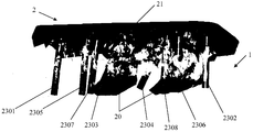
- Fig. 2 is a front view showing a first preferred structure of the wing type angle steel plate of the present invention.
- Figure 3 is a front view of a second preferred structure of the wing-type angle steel plate of the present invention.
- Fig. 4 is a structural schematic view showing the state of use of the first preferred wing-shaped angle steel plate of the present invention.
- Fig. 5 is a structural schematic view showing the state of use of a second preferred wing-shaped angle steel plate of the present invention.
- Fig. 6 is a schematic view showing the structure of a third preferred wing-shaped angle steel plate according to the present invention.
- Fig. 7 is a schematic view showing the structure of a fourth preferred wing-shaped angle steel plate according to the present invention.
- Figure 8 is a side view of Figure 6 or Figure 7.
- Figure 9 is a front elevational view showing the structure of a preferred bone fastening system of the present invention.
- Fig. 10 is a front elevational view showing the structure of a preferred embodiment of the present invention.
- the invention relates to a wing-shaped angle steel plate, comprising a bonding wing part and a body fixing part, wherein the bonding wing part and the body fixing part are fixedly connected to each other, and the fitting wing part is used for supporting a bone fracture, that is, a fracture
- the end portion has a structure matching the inner side surface of the backbone
- the body fixing portion is configured to fix the fitting wing portion, and has a structure matching the front side of the backbone
- the body fixing portion is at a boundary with the fitting wing portion
- At least two first locking holes for passing through the first locking screw are disposed on the portion, the angle of the first locking hole is such that the first locking screw that passes through achieves close contact between the body fixing portion and the fitting wing portion and realizes Supporting the inner side of the backbone
- the body fixing portion is provided with at least two second locking holes for passing through the second locking screw on the structure matching the front side of the backbone, the angle of the second locking hole is such that the The second locking screw realizes
- the conforming flap portion may be designed to completely cover the fracture nonunion or the structure of the nonunion portion of the fracture end, and may also be designed to expose the fracture nonunion or the structure of the nonunion portion of the fracture end.
- the second fixing hole of the body fixing portion disposed on the structure matching the front side of the backbone may be three, and the three second locking holes are arranged in a straight line or in a triangle shape; or the body fixing portion is on the front side with the backbone
- the second locking holes provided on the matching structure may be four or more, and each of the second locking holes is arranged in a straight line or in a polygonal shape.
- the wing-shaped angle steel plate of the present invention may be according to the body.
- the fixing portion is arranged on the structure matching the front side of the backbone
- the number of locking holes is determined to determine the length of the wing-shaped angle steel plate.
- the length of the wing-shaped angle steel plate may be four holes, six holes or eight holes.
- FIG. 2 is a front view of a first preferred structure of the airfoil angle steel plate 2 of the present invention.
- this embodiment includes a fitting wing portion 20 and a body fixing portion 21, and a flap portion 20 and a body.
- the fixing portions 21 are fixedly connected to each other, and preferably the fitting wing portions 20 and the body fixing portions 21 can be made by a stainless steel material integrally forming process; the fitting wing portions 20 are used for supporting, stabilizing the bone fractures and having the inner side of the backbone
- the surface matching structure, and the fitting wing portion 20 has a structure for completely covering the fracture of the fracture, that is, the fracture nonunion or the nonunion portion of the fracture end, to support and stabilize the fracture end and promote fracture healing;
- the portion 21 is for fixing the fitting flap portion 20 and has a structure matching the front side of the backbone, and the body fixing portion 21 is provided with two for passing through the first portion at the boundary with the fitting flap portion 20.
- the first locking hole of the locking screw (such as the reference numerals 2203 and 2204, that is, the first locking hole 2203 and the first locking hole 2204) is fixed when the first locking screw is used to fix the fixed wing portion 20 and fix the body
- the portion 21 and the fitting wing portion 20 are in close contact Drying and achieving inner support for the backbone
- the body fixing portion 21 is provided with two second locking holes for passing through the second locking screw on the structure matching the front side of the backbone (eg, numerals 2201 and 2202, ie, second
- the locking hole 2201 and the second locking hole 2202 are fixed when the second locking screw is used to achieve axial support, fixation, anti-rotation and close-fitting with the front side of the backbone
- the body fixing portion is 21
- the structure matching the front side of the backbone is further provided with two lateral pressing holes for passing through the pressing screws (such as the numerals 2205 and 2206, that is, the lateral pressing holes 2205 and the lateral pressing holes 2206).
- the pressing screw When the pressing screw is locked at an angle in the lateral direction, pressure can be generated between the backbone and the wing-shaped angle steel plate to further strengthen the close fit of the fitting wing portion 20 and the inner side surface of the backbone, and at the same time, the body fixing portion 21 and the front side of the backbone
- the close fitting that is, the close contact/close fit of the wing-shaped angle steel plate 2 and the long bone backbone.
- the second locking hole 2201, the second locking hole 2202, the lateral pressing hole 2205, and the lateral pressing hole 2206 are arranged in an approximately straight line, and the arrangement shape thereof can be arbitrarily set, and only needs to be effective.
- the wing-type angle steel plate 2 proposed by the present invention adopts a structure including an integrally formed body fixing portion 21 and a fitting wing portion 20, and the fitting wing portion 20 has a structure matching the inner side surface of the backbone, which can fracture the fracture.
- the fractures of the end are not healed or the non-connected parts are well stabilized and supported, and the fracture site is accurately positioned and healed, which effectively ensures the stability of the fracture healing;
- the body fixing portion 21 has a structure matching the front side of the backbone. It can realize the axial positioning and fixation of the long bone fracture area, prevent the dislocation of the fracture site, and play a good role of fitting and fixing, further ensuring the accurate positioning, reduction and healing of the auxiliary fracture site.
- FIG. 3 is a front view of a second preferred structure of the airfoil angle steel plate 2 of the present invention.
- the wing angle steel plate 2 also includes a fitting wing portion 20 which is fixedly coupled to each other and each has a specific structure.
- the body fixing portion 21, in this embodiment except for the fitting of the wing portion 20 and its functions are identical to those of the embodiment shown in Fig. 2, the fitting wing portion 20 is still used Supporting the fracture end of the fracture and having a structure matching the inner side of the backbone, with the embodiment of FIG. 2 The difference is that the fitting flap portion 20 shown in the embodiment of Fig.
- the proximal end supports the structure of the fracture end to achieve the support and stabilize the fracture end, and expose the fracture end, accelerate the fracture healing and make the fracture healing state better.
- FIGS. 4 to 8 The structural schematic diagram of the preferred state of use of the wing-shaped angle steel plate 2 proposed by the present invention is as shown in FIGS. 4 to 8.
- the front side of the backbone 1 is the non-contiguous portion of the bone.
- the skin, subcutaneous, quadriceps muscle and periosteum are exposed, and the nonunion is revealed.
- the cortical bone cutting is performed on the nonunion site with a sharp bone knife to fully expose the nonunion.
- Using a Kirschner wire and a bone knife to make a groove in the nonunion site using a Kirschner wire to re-pass the medullary cavity; using a minimally invasive bone drill to take the bone mud and the structural bone graft; Fill the nonunion site, insert the structural bone graft into the medullary cavity of the nonunion site; backfill with the slotted bone; use the extensibility of the skin and muscle to make the subperiosteal strip; then place it under the periosteum as shown in Figure 2 or The flap-type angled steel plate 2 shown in FIG.
- FIG. 3 has the body fixing portion 21 placed on the front side of the backbone and at the same time the flap portion 20 is inserted into the inner side of the backbone to protect the fracture end portion, and fits inside the flap portion 20.
- the side surface is in close contact with the inner side of the backbone to provide a good support and support effect, wherein
- the embodiment shown in Figures 4 and 6 employs a wing-type angled steel plate 2 having a structure of a conforming wing portion 20 that completely covers the fracture end as shown in Figure 2, as shown in Figures 5 and 7.
- the embodiment adopts a wing-shaped angle steel plate 2 having a structure of a fitting wing portion 20 having an exposed fracture end and a distal end and a proximal end of the fracture end, respectively, as shown in FIG.
- the inner side surface of the fixing portion 21 is in close contact with the front side of the backbone to provide a stable anti-rotation fixation function, and the fitting wing portion 20 and the body fixing portion 21 cooperate with each other to perfectly realize effective inner support for the bone fracture. And fixation, assisting the accurate location and healing of the fracture site, effectively ensuring the stability of the fracture healing of the bone fracture.
- the first locking screw 2303 and the first locking screw 2304 respectively pass through the two first locking holes 2203 provided at the portion of the body fixing portion 21 at the boundary with the fitting wing portion 20.
- first locking hole 2204 to achieve the fixing of the fitting wing portion 20, the body fixing portion 21 and the fitting wing portion 20 in close contact with the backbone and the inner side support for the backbone; the second locking screw 2301 and the second locking screw
- the second locking hole 2201 and the second locking hole 2202 are respectively disposed on the structure matching the front side of the backbone body through the body fixing portion 21 to realize axial support, fixation, anti-rotation, and backbone of the body fixing portion 21.
- the front side is closely fitted, as shown in the embodiment shown in Figures 6 and 7 (Fig. 8 is the side view of Fig. 6 or Fig. 7), four second locking holes and four matching second locking screws are provided.
- a second locking screw 2307 and a second locking screw 2308 are provided, and the four second locking screws may be arranged in a straight line or in a polygonal shape to further strengthen the body fixing.
- the close contact/close fit of the wing-shaped angle steel plate 2 and the long bone backbone is achieved.
- the negative pressure drainage tube was left, and the periosteum, myofascial fascia, deep fascia, subcutaneous and skin were closed by suture; the drainage tube was pulled out 48 hours after the operation.
- the patients with fractures had daily passive extreme knee mobility exercises, lower limb limb isometric contraction exercises, and weight-bearing activities under pain tolerance (5 kg toes). The x-ray is reviewed monthly, and the weight-bearing process is determined according to the fracture healing condition; until the patient is fully recovered.
- the invention also relates to a backbone fastening system comprising a wing angle steel plate, at least four locking screws for fixing the wing angle steel plate (at least two first locking screws passing through the first locking hole and at least two a second locking screw passing through the second locking hole) and a trunk outer locking structure for fixing the fracture end, wherein the wing type angle steel plate can adopt the wing type angle steel plate structure as shown in FIG.
- the outer locking structure includes a locking plate and at least two third locking screws for fixing the locking plate, the locking plate having a structure matching the outer side of the backbone, the locking plate being provided with at least two for the structure matching the outer side of the backbone Through the third locking hole of the third locking screw, each of the third locking screws passes through the third locking hole of the locking plate.
- the locking screws (first locking screw and second locking screw) for fixing the wing angle steel plate have a diameter ranging from 2.4 to 4.5 mm; and a locking screw for fixing the wing angle steel plate (first locking screw)
- Both the second locking screw and the locking screw (third locking screw) for fixing the locking plate may be a hollow locking screw or a solid locking screw.
- FIG. 9 and FIG. 10 are schematic structural views showing a state of use of a preferred bone fastening system, including the above-mentioned wing-type angle steel plate 2 and backbone outer locking structure 3 as shown in FIG. 2 or FIG. 3, wherein FIG. 9 A flap type angled steel plate 2 having a structure of a fitting flap portion 20 completely covering the fracture end as shown in Fig. 2 is used, and Fig. 10 is used to have an exposed fracture end as shown in Fig. 3. And at the distal end and the proximal end of the fracture end, respectively support the wing-shaped angle steel plate 2 of the structure of the flap portion 20, and then adopt a plurality of locking screws as shown in FIG. 4-8.
- the retaining wing angle steel plate 2 is fixed in the manner described herein;
- the backbone outer locking structure 3 includes a locking plate 30 and a third locking screw for fixing the locking plate 30.
- the locking plate 30 is preferably a simple rectangular structure and locked
- the plate 30 has a structure matching the outer side surface of the backbone, and the locking plate 30 is provided with a plurality of openings (third locking holes) on the structure matching the outer side of the backbone, corresponding to the number of openings in the locking plate 30, corresponding
- the number of the third locking screws of the fixed locking plate 30 can be set Multiple, and the locking screws can be arranged in parallel with each other or some or all of them are arranged at an angle to each other.
- the third locking screw can select a hollow locking screw or a solid locking screw, the number of screws, the shape of the screw arrangement, and the screw and the locking plate.
- the angle between 30 can be set according to actual needs, only need to ensure effective fixation, that is, through reasonable layout, each locking screw bears different stresses respectively, so as to achieve accurate positioning and stable resetting of the auxiliary fracture site, which can maximize the reinforcement. Optimal fixation stability, and to the greatest extent possible to ensure less damage to patients in actual use.
- the outer trunk locking structure 3 and the wing-shaped angle steel plate 2 are both The same conventional anterior lateral incision can be placed together, and only one incision can be used to achieve the implantation of the bone fixation system of the present invention, and the damage surface, the degree of damage and the amount of bleeding are usually smaller, postoperative healing and The recovery speed is faster.
- the working principle and usage of the wing-type angle steel plate 2 shown in Figure 2-8 are the same as described above.
- the outer trunk locking structure 3 adopts the structure of the locking plate 30, and the locking plate 30 is in close contact with the outer side surface of the backbone.
- a plurality of third locking screws pass through the opening of the locking plate 30 and then enter from the outer side of the backbone and traverse the backbone. To fix the fracture end.
- the outer lateral locking structure 3 and the wing-shaped angle steel plate 2 cooperate to further strengthen the effective support and fixation for the bone fracture, and assist the accurate positioning of the fracture site, thereby effectively ensuring the stability of the bone fracture after the reduction.
Landscapes
- Health & Medical Sciences (AREA)
- Orthopedic Medicine & Surgery (AREA)
- Surgery (AREA)
- Life Sciences & Earth Sciences (AREA)
- Heart & Thoracic Surgery (AREA)
- Nuclear Medicine, Radiotherapy & Molecular Imaging (AREA)
- Engineering & Computer Science (AREA)
- Biomedical Technology (AREA)
- Medical Informatics (AREA)
- Molecular Biology (AREA)
- Animal Behavior & Ethology (AREA)
- General Health & Medical Sciences (AREA)
- Public Health (AREA)
- Veterinary Medicine (AREA)
- Neurology (AREA)
- Surgical Instruments (AREA)
- Prostheses (AREA)
Abstract
Description
Claims (10)
- 一种护翼型角钢板,其特征在于,包括贴合护翼部和本体固定部,所述贴合护翼部和本体固定部相互固定连接,所述贴合护翼部用于撑护骨折断端且具有与骨干内侧面相匹配的结构,所述本体固定部用于固定贴合护翼部且具有与骨干前侧面相匹配的结构,所述本体固定部在与贴合护翼部相交界处的部位上设置有至少两个用于穿过第一锁定螺钉的第一锁定孔,所述第一锁定孔的角度使得穿过的第一锁定螺钉实现本体固定部和贴合护翼部紧密接触骨干以及实现对骨干的内侧支撑,所述本体固定部在与骨干前侧面相匹配的结构上设置有至少两个用于穿过第二锁定螺钉的第二锁定孔,所述第二锁定孔的角度使得穿过的第二锁定螺钉实现本体固定部紧密接触骨干以及控制本体固定部旋转和轴向稳定。
- 根据权利要求1所述的护翼型角钢板,其特征在于,所述贴合护翼部具有完全罩住骨折断端的结构。
- 根据权利要求1所述的护翼型角钢板,其特征在于,所述贴合护翼部具有露出骨折断端且在骨折断端的远端和近端分别撑护骨折断端的结构。
- 根据权利要求1所述的护翼型角钢板,其特征在于,所述贴合护翼部和本体固定部采用一体成型工艺制作而成。
- 根据权利要求1至4之一所述的护翼型角钢板,其特征在于,所述本体固定部在与骨干前侧面相匹配的结构上还设置有至少两个用于穿过加压螺钉的横向加压孔,所述横向加压孔的角度使得穿过的加压螺钉在骨干与护翼型角钢板之间产生压力。
- 根据权利要求5所述的护翼型角钢板,其特征在于,所述本体固定部在与骨干前侧面相匹配的结构上设置的第二锁定孔为三个,三个第二锁定孔呈直线排列或呈三角形排列。
- 根据权利要求5所述的护翼型角钢板,其特征在于,所述本体固定部在与骨干前侧面相匹配的结构上设置的第二锁定孔为四个以上,四个以上的第二锁定孔呈直线排列或呈多边形排列。
- 一种骨干固定系统,其特征在于,包括权利要求1至7之一所述的护翼型角钢板,还包括用于固定护翼型角钢板的穿过第一锁定孔的第一锁定螺钉和穿过第二锁定孔的第二锁定螺钉以及用于固定骨折断端的骨干外侧锁定结构,所述骨干外侧锁定结构包括锁定板以及用于固定锁定板的至少两个第三锁定螺钉,所述锁定板具有与骨干外侧面相匹配的结构,所述锁定板在与骨干外侧面相匹配的结构上设置有至少两个用于穿过第三锁定螺钉的第三锁定孔,各所述第三锁定螺钉穿过所述锁定板的第三锁定孔。
- 根据权利要求8所述的骨干固定系统,其特征在于,所述用于固定护翼型角钢板的第一锁定螺钉和第二锁定螺钉的直径范围均为2.4-4.5mm。
- 根据权利要求8或9所述的骨干固定系统,其特征在于,所述第一锁定螺钉和/或第 二锁定螺钉和/或第三锁定螺钉为空心锁定螺钉或实心锁定螺钉。
Priority Applications (6)
| Application Number | Priority Date | Filing Date | Title |
|---|---|---|---|
| ES16919528T ES3047358T3 (en) | 2016-10-18 | 2016-10-18 | Protective wing type angle steel plate and skeleton fixing system |
| PCT/CN2016/102447 WO2018072100A1 (zh) | 2016-10-18 | 2016-10-18 | 一种护翼型角钢板以及骨干固定系统 |
| EP16919528.6A EP3530222B1 (en) | 2016-10-18 | 2016-10-18 | Protective wing type angle steel plate and skeleton fixing system |
| JP2019520854A JP2019533507A (ja) | 2016-10-18 | 2016-10-18 | ウイング型アングル鋼板及び骨幹固定システム |
| US16/343,152 US11116555B2 (en) | 2016-10-18 | 2016-10-18 | Wing-shaped angle steel plate and a bone shaft fixation system |
| JP2021165590A JP2022002747A (ja) | 2016-10-18 | 2021-10-07 | ウイング型アングル鋼板及び骨幹固定システム |
Applications Claiming Priority (1)
| Application Number | Priority Date | Filing Date | Title |
|---|---|---|---|
| PCT/CN2016/102447 WO2018072100A1 (zh) | 2016-10-18 | 2016-10-18 | 一种护翼型角钢板以及骨干固定系统 |
Publications (1)
| Publication Number | Publication Date |
|---|---|
| WO2018072100A1 true WO2018072100A1 (zh) | 2018-04-26 |
Family
ID=62018109
Family Applications (1)
| Application Number | Title | Priority Date | Filing Date |
|---|---|---|---|
| PCT/CN2016/102447 Ceased WO2018072100A1 (zh) | 2016-10-18 | 2016-10-18 | 一种护翼型角钢板以及骨干固定系统 |
Country Status (5)
| Country | Link |
|---|---|
| US (1) | US11116555B2 (zh) |
| EP (1) | EP3530222B1 (zh) |
| JP (2) | JP2019533507A (zh) |
| ES (1) | ES3047358T3 (zh) |
| WO (1) | WO2018072100A1 (zh) |
Families Citing this family (3)
| Publication number | Priority date | Publication date | Assignee | Title |
|---|---|---|---|---|
| JP2019533507A (ja) * | 2016-10-18 | 2019-11-21 | 華 陳 | ウイング型アングル鋼板及び骨幹固定システム |
| CN112826579A (zh) * | 2019-12-02 | 2021-05-25 | 青岛大学附属医院 | 静动转换型人字嵴锁定动态加压钢板系统 |
| CN117462228A (zh) * | 2023-10-31 | 2024-01-30 | 上海中冶医院 | 一种指骨接骨板 |
Citations (5)
| Publication number | Priority date | Publication date | Assignee | Title |
|---|---|---|---|---|
| CN2074170U (zh) * | 1990-11-10 | 1991-04-03 | 长沙铁路分局长沙医院 | U型接骨板 |
| US5352228A (en) * | 1993-05-10 | 1994-10-04 | Kummer Frederick J | Apparatus and method to provide compression for a locked intramedullary nail |
| US20030069581A1 (en) * | 2001-10-04 | 2003-04-10 | Stinson David T. | Universal intramedullary nails, systems and methods of use thereof |
| CN2662843Y (zh) * | 2003-04-10 | 2004-12-15 | 郭建欣 | 股骨髁部环抱式接骨板 |
| CN201052174Y (zh) * | 2007-07-10 | 2008-04-30 | 徐仲棉 | 一种胫骨远端外侧接骨板 |
Family Cites Families (17)
| Publication number | Priority date | Publication date | Assignee | Title |
|---|---|---|---|---|
| US4776330A (en) * | 1986-06-23 | 1988-10-11 | Pfizer Hospital Products Group, Inc. | Modular femoral fixation system |
| JPH063551Y2 (ja) * | 1989-01-17 | 1994-02-02 | 旭光学工業株式会社 | 骨接合用プレート |
| US7316687B2 (en) * | 2001-08-24 | 2008-01-08 | Zimmer Technology, Inc. | Blade plate and instruments |
| JP2003210478A (ja) * | 2002-01-18 | 2003-07-29 | Ai-Medic:Kk | 尺骨近位端粉砕骨折固定用プレート |
| EP1713409B1 (en) * | 2004-01-23 | 2013-01-16 | Biomet C.V. | System for stabilization of fractures of convex articular bone surfaces including subchondral support structure |
| US8906070B2 (en) * | 2005-10-25 | 2014-12-09 | Robert J. Medoff | Bone fixation device and method |
| EP2053980B1 (de) * | 2006-08-15 | 2016-09-07 | Heiko Durst | Trochanter-zügelplatte |
| US20110087229A1 (en) * | 2009-10-12 | 2011-04-14 | University Of Utah | Bone fixation and compression systems |
| ES2464494T3 (es) * | 2010-07-09 | 2014-06-03 | Medartis Ag | Sistema de osteosíntesis |
| TWM417131U (en) * | 2010-12-24 | 2011-12-01 | Univ Nat Taiwan Science Tech | Improving bony plate structure |
| DE102011079821A1 (de) * | 2011-07-26 | 2013-01-31 | Rita Leibinger GmbH & Co. KG | Tibiaimplantat zur Straffung der Kniescheibenbänder |
| US9101421B2 (en) * | 2011-12-12 | 2015-08-11 | Solana Surgical, Llc | Metatarsal fixation device, system and method |
| US9283008B2 (en) * | 2012-12-17 | 2016-03-15 | Toby Orthopaedics, Inc. | Bone plate for plate osteosynthesis and method for use thereof |
| CN104188717A (zh) * | 2014-09-24 | 2014-12-10 | 苏州欣荣博尔特医疗器械有限公司 | 带侧翼爪形大粗隆锁定接骨板 |
| CN104814784B (zh) * | 2015-04-28 | 2016-09-07 | 丽水市中心医院 | 一种肱骨远端后外侧双柱固定锁定接骨板 |
| CN105640635B (zh) * | 2016-02-03 | 2018-08-31 | 哈尔滨医科大学 | 一种股骨假体周围骨折翻修锁定钢板 |
| JP2019533507A (ja) * | 2016-10-18 | 2019-11-21 | 華 陳 | ウイング型アングル鋼板及び骨幹固定システム |
-
2016
- 2016-10-18 JP JP2019520854A patent/JP2019533507A/ja active Pending
- 2016-10-18 ES ES16919528T patent/ES3047358T3/es active Active
- 2016-10-18 EP EP16919528.6A patent/EP3530222B1/en active Active
- 2016-10-18 US US16/343,152 patent/US11116555B2/en active Active
- 2016-10-18 WO PCT/CN2016/102447 patent/WO2018072100A1/zh not_active Ceased
-
2021
- 2021-10-07 JP JP2021165590A patent/JP2022002747A/ja active Pending
Patent Citations (5)
| Publication number | Priority date | Publication date | Assignee | Title |
|---|---|---|---|---|
| CN2074170U (zh) * | 1990-11-10 | 1991-04-03 | 长沙铁路分局长沙医院 | U型接骨板 |
| US5352228A (en) * | 1993-05-10 | 1994-10-04 | Kummer Frederick J | Apparatus and method to provide compression for a locked intramedullary nail |
| US20030069581A1 (en) * | 2001-10-04 | 2003-04-10 | Stinson David T. | Universal intramedullary nails, systems and methods of use thereof |
| CN2662843Y (zh) * | 2003-04-10 | 2004-12-15 | 郭建欣 | 股骨髁部环抱式接骨板 |
| CN201052174Y (zh) * | 2007-07-10 | 2008-04-30 | 徐仲棉 | 一种胫骨远端外侧接骨板 |
Non-Patent Citations (1)
| Title |
|---|
| See also references of EP3530222A4 * |
Also Published As
| Publication number | Publication date |
|---|---|
| ES3047358T3 (en) | 2025-12-03 |
| JP2022002747A (ja) | 2022-01-11 |
| US11116555B2 (en) | 2021-09-14 |
| JP2019533507A (ja) | 2019-11-21 |
| EP3530222C0 (en) | 2025-08-06 |
| EP3530222B1 (en) | 2025-08-06 |
| EP3530222A1 (en) | 2019-08-28 |
| EP3530222A4 (en) | 2019-11-06 |
| US20190314066A1 (en) | 2019-10-17 |
Similar Documents
| Publication | Publication Date | Title |
|---|---|---|
| CN107095714B (zh) | 股骨颈骨折植入物 | |
| EP2568891B1 (en) | Pediatric intramedullary nail | |
| ITVR970003A1 (it) | Chiodo endomidollare per il trattamento delle fratture dell'anca | |
| KR20110128317A (ko) | 소아 장골 지지 또는 고정판 | |
| US10792082B2 (en) | Condylar fracture fixation system | |
| US2518019A (en) | Intramedullary splint | |
| JP6467052B2 (ja) | 骨折プレート固定法 | |
| JP2022002747A (ja) | ウイング型アングル鋼板及び骨幹固定システム | |
| JP6751995B2 (ja) | 二方向固定鋼板及び骨幹固定システム | |
| CN207400790U (zh) | 一种双向固定钢板以及骨干固定系统 | |
| CN205286506U (zh) | 一种髓内钉 | |
| CN106236238B (zh) | 一种护翼型角钢板以及骨干固定系统 | |
| CN207400789U (zh) | 一种护翼型角钢板以及骨干固定系统 | |
| BR112021006098A2 (pt) | sistema de redução de fratura óssea longa | |
| CN106344141B (zh) | 一种双向固定钢板以及骨干固定系统 | |
| EP3348217A1 (en) | Plate for synthesis of a bone fracture and kit comprising such a plate | |
| CN215079506U (zh) | 一种胫骨近端辅助延长锁定接骨板 | |
| CN221533977U (zh) | 一种拇外翻微创截骨矫形固定装置 | |
| CN211749996U (zh) | 一种用于四肢骨折的导航锁定钢板及其附件 | |
| US12491013B2 (en) | Orthopaedic implant and system | |
| RU2820924C1 (ru) | Устройство для удержания винта на рабочем конце отвертки при остеосинтезе | |
| US9763708B2 (en) | Intramedullary fixation device | |
| CN204744373U (zh) | 一种组合式髓内钉 | |
| WO2006133643A1 (fr) | Clou intramedullaire | |
| RO127481B1 (ro) | Implant pentru fracturile de paletă humerală |
Legal Events
| Date | Code | Title | Description |
|---|---|---|---|
| 121 | Ep: the epo has been informed by wipo that ep was designated in this application |
Ref document number: 16919528 Country of ref document: EP Kind code of ref document: A1 |
|
| ENP | Entry into the national phase |
Ref document number: 2019520854 Country of ref document: JP Kind code of ref document: A |
|
| NENP | Non-entry into the national phase |
Ref country code: DE |
|
| ENP | Entry into the national phase |
Ref document number: 2016919528 Country of ref document: EP Effective date: 20190520 |
|
| WWG | Wipo information: grant in national office |
Ref document number: 2016919528 Country of ref document: EP |