WO2018073911A1 - ウインドウガラス支持構造 - Google Patents
ウインドウガラス支持構造 Download PDFInfo
- Publication number
- WO2018073911A1 WO2018073911A1 PCT/JP2016/080951 JP2016080951W WO2018073911A1 WO 2018073911 A1 WO2018073911 A1 WO 2018073911A1 JP 2016080951 W JP2016080951 W JP 2016080951W WO 2018073911 A1 WO2018073911 A1 WO 2018073911A1
- Authority
- WO
- WIPO (PCT)
- Prior art keywords
- window glass
- adhesive
- bonding portion
- window
- window frame
- Prior art date
- Legal status (The legal status is an assumption and is not a legal conclusion. Google has not performed a legal analysis and makes no representation as to the accuracy of the status listed.)
- Ceased
Links
Images

Classifications
-
- B—PERFORMING OPERATIONS; TRANSPORTING
- B60—VEHICLES IN GENERAL
- B60J—WINDOWS, WINDSCREENS, NON-FIXED ROOFS, DOORS, OR SIMILAR DEVICES FOR VEHICLES; REMOVABLE EXTERNAL PROTECTIVE COVERINGS SPECIALLY ADAPTED FOR VEHICLES
- B60J1/00—Windows; Windscreens; Accessories therefor
- B60J1/004—Mounting of windows
- B60J1/006—Mounting of windows characterised by fixation means such as clips, adhesive, etc.
-
- E—FIXED CONSTRUCTIONS
- E06—DOORS, WINDOWS, SHUTTERS, OR ROLLER BLINDS IN GENERAL; LADDERS
- E06B—FIXED OR MOVABLE CLOSURES FOR OPENINGS IN BUILDINGS, VEHICLES, FENCES OR LIKE ENCLOSURES IN GENERAL, e.g. DOORS, WINDOWS, BLINDS, GATES
- E06B3/00—Window sashes, door leaves, or like elements for closing wall or like openings; Layout of fixed or moving closures, e.g. windows in wall or like openings; Features of rigidly-mounted outer frames relating to the mounting of wing frames
- E06B3/54—Fixing of glass panes or like plates
- E06B3/56—Fixing of glass panes or like plates by means of putty, cement, or adhesives only
-
- B—PERFORMING OPERATIONS; TRANSPORTING
- B60—VEHICLES IN GENERAL
- B60J—WINDOWS, WINDSCREENS, NON-FIXED ROOFS, DOORS, OR SIMILAR DEVICES FOR VEHICLES; REMOVABLE EXTERNAL PROTECTIVE COVERINGS SPECIALLY ADAPTED FOR VEHICLES
- B60J1/00—Windows; Windscreens; Accessories therefor
- B60J1/004—Mounting of windows
-
- B—PERFORMING OPERATIONS; TRANSPORTING
- B60—VEHICLES IN GENERAL
- B60J—WINDOWS, WINDSCREENS, NON-FIXED ROOFS, DOORS, OR SIMILAR DEVICES FOR VEHICLES; REMOVABLE EXTERNAL PROTECTIVE COVERINGS SPECIALLY ADAPTED FOR VEHICLES
- B60J1/00—Windows; Windscreens; Accessories therefor
- B60J1/02—Windows; Windscreens; Accessories therefor arranged at the vehicle front, e.g. structure of the glazing, mounting of the glazing
Definitions
- the present invention relates to a window glass support structure.
- the window structure described in Patent Document 1 includes a window frame and a closing member formed so as to close the window formed in the window frame.
- the window structure described in Patent Document 1 includes a first adhesive portion interposed between the window frame and the peripheral edge of the closing member and bonding the closing member to the window frame, and the window frame and the closing member. And a second bonding portion provided in line with a part of the first bonding portion with the peripheral portion.
- the vibration accompanying the traveling of the vehicle is input to the vehicle body to cause deformation of the vehicle body, and the adhesive supporting the window glass to the window frame may expand or contract, thereby promoting deformation of the opening of the window frame .
- the support structure as described in Patent Document 1 there is a problem that although the vibration of the window glass can be reduced, the deformation of the window frame can not be sufficiently reduced. Since the deformation of the opening of the window frame that may occur at the time of occurrence of vehicle vibration affects the steering stability, ride comfort, quietness and the like of the vehicle, it is necessary to take measures to sufficiently reduce it.
- the present invention provides a window glass supporting structure capable of improving the steering stability, the riding comfort, the quietness and the like of the vehicle by sufficiently reducing the deformation of the opening of the window frame which may occur at the time of the occurrence of the vehicle vibration. Intended to be provided.
- a window glass support structure comprises a window frame, a window glass, and an adhesion part.
- the window frame has an opening and a joint formed along the inner peripheral edge of the opening and bonded to the outer peripheral edge of the window glass.
- the window glass has a plurality of corner portions formed at corner portions in the outer peripheral edge portion of the window glass, and a connection side portion formed at the outer peripheral edge portion of the window glass and connecting adjacent corner portions.
- the bonding portion has a first bonding portion bonding the corner portion of the window glass to the window frame, and a second bonding portion bonding the connecting side portion of the window glass to the window frame.
- the adhesion per unit circumferential length in the first bonded portion is larger than the adhesion per unit circumferential length in the second bonded portion.
- the steering stability, the riding comfort, the quietness and the like of the vehicle can be improved by sufficiently reducing the deformation of the opening of the window frame which may occur at the time of vehicle vibration. it can.
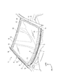
- FIG. 1 is a perspective view of a window glass support structure according to an embodiment of the present invention.
- FIG. 2 is an exploded perspective view of a window glass support structure according to an embodiment of the present invention.
- FIG. 1 A window glass supporting structure according to an embodiment of the present invention will be described based on FIG. 1 and FIG.
- a window frame 2 is formed at the front of the vehicle body 1 according to the present embodiment, and a window glass 3 is supported by the window frame 2.
- the outer peripheral portion of the window glass 3 is bonded to the bonding portion 11 of the window frame 2 by interposing the bonding portion 4 between the outer peripheral portion of the window glass 3 and the bonding portion 11 of the window frame 2 .
- reference numeral 5 denotes a black print portion formed on the outer peripheral edge of the window glass 3.
- the window frame 2 is disposed on the upper side of the window glass 3, a pair of left and right front pillars 6 and 6 disposed on both sides in the vehicle width direction of the window glass 3, a cowl portion 7 disposed below the window glass 3, and And a front roof rail 8.
- the window frame 2 is a rectangular frame-like body having a rectangular opening 10 and a joint 11 formed along the inner peripheral edge of the opening 10 and bonded to the outer peripheral edge of the window glass 3. is there.
- the joint portion 11 of the window frame 2 has a flange portion 12 formed over the entire circumference at the inner peripheral edge portion of the opening portion 10, and the flange portion 12 includes the front pillar 6, the cowl portion 7 and the front roof rail 8.
- an extending portion 13 is formed so as to project from the flange portion 12 to the inner peripheral side.
- the formation of the extended portion 13 enlarges the bonding surface (area) of the bonding portion 11 of the window frame 2 corresponding to the corner portion 14 of the window glass 3.
- the extended portion 13 is covered with the black print portion 5 of the window glass 3 and does not affect the visibility of the occupant.
- the window glass 3 has a plurality of corner portions 14 formed at corner portions in the outer peripheral edge portion of the window glass 3 and a connecting side portion 15 formed at the outer peripheral edge portion of the window glass 3 and connecting adjacent corner portions 14 Is a square glass having
- the "corner" in the window glass 3 includes not only the R-processed or C-processed portion of the polygonal glass corner but also the peripheral portion of the R-processed or C-processed portion. .
- the bonding portion 4 includes a first bonding portion 16 interposed between the corner portion 14 of the window glass 3 and the bonding portion 11 of the window frame 2, and the bonding portion 11 of the connecting side portion 15 of the window glass 3 and the window frame 2. And a second adhesive portion 17 interposed therebetween.
- the adhesion per unit circumferential length of the first bonding portion 16 is set larger than the adhesion per unit circumferential length of the second bonding portion 17.
- the first adhesive 16 and the second adhesive 17 are applied to the flange 12 and the extended portion 13 of the window frame 2 in a linear manner along the circumferential direction of the opening 10. It is composed of (glass glue).
- the adhesive for glass is not particularly limited, and a known adhesive for glass can be used.
- the application of the adhesive to the bonding portion 11 forms an application line 18 of the adhesive on the bonding portion 11.
- the number of application lines 18 of adhesive in the first bonding unit 16 is set to be larger than the number of application lines 18 of adhesive in the second bonding unit 17.
- the adhesive strength per unit circumferential direction length of the first adhesive portion 16 is enhanced. That is, the coating amount of the adhesive per unit circumferential length in the first bonding portion 16 is increased as compared with the coating amount of the adhesive per unit circumferential length in the second bonding portion 17.
- the number of the application lines 18 of the adhesive in the second bonding portion 17 is only one (one row), but the number of the application lines 18 of the adhesive in the first bonding portion 16 is plural (a plurality of rows ). Further, in the present embodiment, the number of the coating lines 18 in the first bonding portion 16 corresponding to the lower portion of the window glass 3 is larger than the number of the coating lines 18 in the first bonding portion 16 corresponding to the upper portion of the window glass 3 It is set. The number of coating lines 18 in the first bonding portion 16 corresponding to the lower portion of the window glass 3 is the same as the number of coating lines 18 in the first bonding portion 16 corresponding to the upper portion of the window glass 3. It may be set.
- the number of coating lines 18 in the first bonding portion 16 corresponding to the upper portion of the window glass 3 is greater than the number of coating lines 18 in the first bonding portion 16 corresponding to the lower portion of the window glass 3. Many settings may be made.
- the width of the application line 18 of the adhesive in the first adhesion section 16 is set larger than the width of the application line 18 of the adhesive in the second adhesion section 17.
- the adhesion per unit circumferential direction length in the above may be increased. Even in this case, the coating amount of the adhesive per unit circumferential length in the first bonding portion 16 is increased compared to the coating amount of the adhesive per unit circumferential length in the second bonding portion 17 It is possible.
- the adhesion is set to be enhanced at all the four corner portions 14 of the window glass 3, but the setting site to enhance the adhesion is limited to three places or less, or only one place. You may do so.
- the window glass supporting structure according to the present embodiment is interposed between the window frame 2 formed on the vehicle body 1, the window glass 3 supported by the window frame 2, the window glass 3 and the window frame 2 And an adhesive unit 4.
- the window frame 2 has an opening 10 and a joint 11 formed along the inner peripheral edge of the opening 10 and bonded to the outer peripheral edge of the window glass 3.
- the window glass 3 has a plurality of corner portions 14 formed at corner portions in the outer peripheral edge portion of the window glass 3 and a connecting side portion 15 formed at the outer peripheral edge portion of the window glass 3 and connecting adjacent corner portions 14 Have.
- the bonding portion 4 includes a first bonding portion 16 interposed between the corner portion 14 of the window glass 3 and the bonding portion 11 of the window frame 2, and the bonding portion 11 of the connecting side portion 15 of the window glass 3 and the window frame 2. And a second adhesive portion 17 interposed therebetween.
- the adhesion per unit circumferential length of the first bonding portion 16 is larger than the adhesion per unit circumferential length of the second bonding portion 17.
- the analysis of the deformation of the opening 10 of the window frame 2 which may occur at the time of the occurrence of the vehicle vibration shows that the deformation of the corner 14 of the window glass 3 is the largest.
- the corner 14 of the window glass 3 has the highest degree of contribution in order to reduce the deformation of the opening 10 of the window frame 2 that may occur when vehicle vibration occurs.
- the adhesive strength of the first bonding portion 16 interposed between the corner portion 14 of the window glass 3 and the bonding portion 11 of the window frame 2 is enhanced. By doing this, it is possible to reduce the amount of deformation of the vehicle body 1 on the outer periphery than the window glass 3.
- the steering stability, the riding comfort, the quietness, etc. of the vehicle can be sufficiently reduced by sufficiently reducing the deformation of the opening 10 of the window frame 2 that may occur during vehicle vibration. Can be improved.
- the bonding portion 11 is formed so as to protrude from the flange portion 12 formed over the entire circumference at the inner peripheral edge of the opening 10 and the flange portion 12 corresponding to the corner portion 14 of the window glass 3 to the inner peripheral side And the extended portion 13 to be
- the bonding portion 4 is formed by bonding the outer peripheral edge portion of the window glass 3 and the bonding portion 11 of the window frame 2 through an adhesive applied in a linear manner along the circumferential direction to the bonding portion 11 of the window frame 2. It adheres.
- the number of application lines 18 of adhesive in the first bonding portion 16 is larger than the number of application lines 18 of adhesive in the second bonding portion 17.
- the adhesion per unit circumferential length in the first bonding portion 16 is larger than the adhesion per unit circumferential length in the second bonding portion 17.
- the degree of freedom of the adhesive application process should be increased. Is possible.
- the width of the coating line 18 of the adhesive in the first bonding portion 16 is set larger than the width of the coating line 18 of the adhesive in the second bonding portion 17.
- the adhesion per unit circumferential length in the first bonding portion 16 it is possible to set the adhesion per unit circumferential length in the first bonding portion 16 to be larger than the adhesion per unit circumferential length in the second bonding portion 17.
- the same adhesive can be used for the first bonding unit 16 and the second bonding unit 17 and does not depend on the specifications of the adhesive or the conditions of equipment, the degree of freedom of the adhesive application process should be increased. Is possible.
- the above-mentioned embodiment showed the example which applied the present invention to the support structure of the windshield of a vehicle, it is not limited to this.
- the present invention can also be applied to, for example, a support structure for a rear window glass of a vehicle or a support structure for a window glass for a triangular window.
- the adhesive force of the first adhesive portion may be enhanced by using adhesives having different adhesive strengths for the first adhesive portion and the second adhesive portion, respectively. That is, an adhesive having high adhesive strength may be used for the first adhesive portion, and an adhesive having low adhesive strength as compared to the adhesive may be used for the second adhesive portion.
- Reference Signs List 1 vehicle body 2 window frame 3 window glass 4 bonding portion 10 opening 11 bonding portion 12 flange portion 13 extending portion 14 corner portion 15 connecting side portion 16 first bonding portion 17 second bonding portion 18 coating line
Landscapes
- Engineering & Computer Science (AREA)
- Mechanical Engineering (AREA)
- Civil Engineering (AREA)
- Structural Engineering (AREA)
- Securing Of Glass Panes Or The Like (AREA)
- Window Of Vehicle (AREA)
- Body Structure For Vehicles (AREA)
- Seal Device For Vehicle (AREA)
Abstract
窓枠(2)は、開口部(10)と、開口部(10)の内周縁部に沿って形成され、ウインドウガラス(3)の外周縁部と接着される接合部(11)とを有する。ウインドウガラス(3)は、ウインドウガラス(3)の外周縁部における角部分に形成された複数の角部(14)と、ウインドウガラス(3)の外周縁部に形成され、隣接する角部(14)間を結ぶ連結辺部(15)とを有する。接着部(4)は、ウインドウガラス(3)の角部(14)を窓枠(2)に接着する第一接着部(16)と、ウインドウガラス(3)の連結辺部(15)を窓枠(2)に接着する第二接着部(17)とを有する。第一接着部(16)における単位周方向長さ当たりの接着力が、第二接着部(17)における単位周方向長さ当たりの接着力よりも大きい。
Description
本発明は、ウインドウガラス支持構造に関する。
ウインドウガラスを車体の窓枠に支持する構造としては、例えば特許文献1に記載されたものがある。
特許文献1に記載された窓部構造は、窓枠部と、窓枠部に形成された窓を閉止可能に形成された閉止部材と、を備える。特許文献1に記載された窓部構造は、窓枠部と閉止部材の周縁部との間に介在し、窓枠部に閉止部材を接着させる第一接着部と、窓枠部と閉止部材の周縁部との間で第一接着部の一部に並べて設けられた第二接着部と、をさらに備える。
特許文献1に記載された窓部構造によれば、車体構造に対する制約を減らしつつ閉止部材の振動特性を調整することが可能である。
車両走行に伴う振動が車体に入力されて車体の変形が発生し、ウインドウガラスを窓枠に対して支持する接着剤が伸縮することにより、窓枠の開口部の変形が促進されることがある。特許文献1に記載されているような支持構造であると、ウインドウガラスの振動は低減することができても、窓枠の変形を十分に低減できないという問題がある。車両振動発生時に生じ得る窓枠の開口部の変形は、車両の操縦安定性、乗り心地、静粛性等に影響があるので、十分に低減するように対策をする必要がある。
そこで、本発明は、車両振動発生時に生じ得る窓枠の開口部の変形を十分に低減することにより、車両の操縦安定性、乗り心地、静粛性等を向上することができるウインドウガラス支持構造を提供することを目的とする。
本発明に係るウインドウガラス支持構造は、窓枠と、ウインドウガラスと、接着部と、を備える。窓枠は、開口部と、開口部の内周縁部に沿って形成され、ウインドウガラスの外周縁部と接着される接合部とを有する。ウインドウガラスは、ウインドウガラスの外周縁部における角部分に形成された複数の角部と、ウインドウガラスの外周縁部に形成され、隣接する角部間を結ぶ連結辺部とを有する。接着部は、ウインドウガラスの角部を窓枠に接着する第一接着部と、ウインドウガラスの連結辺部を窓枠に接着する第二接着部とを有する。第一接着部における単位周方向長さ当たりの接着力が、第二接着部における単位周方向長さ当たりの接着力よりも大きい。
本発明に係るウインドウガラス支持構造によれば、車両振動発生時に生じ得る窓枠の開口部の変形を十分に低減することにより、車両の操縦安定性、乗り心地、静粛性等を向上することができる。
以下、本発明の実施形態を図面と共に詳述する。
本実施形態では、本発明を車両におけるフロントウインドウガラスの支持構造に適用した例を示す。なお、図中、矢印FRは車両前方を示し、矢印UPRは車両上方を示す。
本発明の実施形態に係るウインドウガラス支持構造を図1及び図2に基づいて説明する。
図1及び図2に示すように、本実施形態による車体1の前部に、窓枠2が形成されており、窓枠2には、ウインドウガラス3が支持されている。ウインドウガラス3の外周縁部と窓枠2の接合部11との間に接着部4を介在させることにより、ウインドウガラス3の外周縁部を窓枠2の接合部11に対して接着している。なお、図中、符号5は、ウインドウガラス3の外周縁部に形成された黒プリント部を示している。
窓枠2は、ウインドウガラス3の車幅方向両側に配置される左右一対のフロントピラー6,6と、ウインドウガラス3の下側に配置されるカウル部7と、ウインドウガラス3の上側に配置されるフロントルーフレール8とから構成される。窓枠2は、四角形状の開口部10と、開口部10の内周縁部に沿って形成され、ウインドウガラス3の外周縁部と接着される接合部11とを有する四角形状の枠状体である。
窓枠2の接合部11は、開口部10の内周縁部に全周に亘って形成されたフランジ部12を有しており、フランジ部12は、フロントピラー6、カウル部7及びフロントルーフレール8に設けられている。そして、ウインドウガラス3の角部14に対応するフランジ部12には、フランジ部12から内周側に張り出す延設部13が形成されている。延設部13の形成により、ウインドウガラス3の角部14に対応する窓枠2の接合部11の接着面(面積)を拡大させている。延設部13は、ウインドウガラス3の黒プリント部5で覆われており、乗員の視認性に影響を与えることはない。
ウインドウガラス3は、ウインドウガラス3の外周縁部における角部分に形成された複数の角部14と、ウインドウガラス3の外周縁部に形成され、隣接する角部14間を結ぶ連結辺部15とを有する四角形ガラスである。ここで、ウインドウガラス3における「角部」とは、多角形状のガラスの隅部におけるR加工やC加工された部分のみだけでなく、そのR加工やC加工された部分の周辺部分も含むものとする。
接着部4は、ウインドウガラス3の角部14と窓枠2の接合部11との間に介在する第一接着部16と、ウインドウガラス3の連結辺部15と窓枠2の接合部11との間に介在する第二接着部17とを有する。そして、第一接着部16における単位周方向長さ当たりの接着力は、第二接着部17における単位周方向長さ当たりの接着力よりも大きく設定されている。
具体的には、第一接着部16及び第二接着部17は、窓枠2のフランジ部12及び延設部13に開口部10の周方向に沿って線状に塗布されたガラス用接着剤(ガラスグルー)により構成されている。ガラス用接着剤は特に限定はされず、公知のガラス用接着剤を用いることができる。接着剤の接合部11への塗布により、接着剤の塗布線18が接合部11に形成される。
本実施形態では、図2に示すように、第一接着部16における接着剤の塗布線18の本数を、第二接着部17における接着剤の塗布線18の本数よりも多く設定することにより、第一接着部16における単位周方向長さ当たりの接着力を高めている。すなわち、第一接着部16における単位周方向長さ当たりの接着剤の塗布量を、第二接着部17における単位周方向長さ当たりの接着剤の塗布量と比較して増加させている。
本実施形態では、第二接着部17における接着剤の塗布線18の本数は一本(一列)のみであるが、第一接着部16における接着剤の塗布線18の本数を複数本(複数列)としている。また、本実施形態では、ウインドウガラス3の下部に対応する第一接着部16における塗布線18の本数を、ウインドウガラス3の上部に対応する第一接着部16における塗布線18の本数よりも多く設定している。これに限定はされず、ウインドウガラス3の下部に対応する第一接着部16における塗布線18の本数を、ウインドウガラス3の上部に対応する第一接着部16における塗布線18の本数と同数に設定してもよい。本実施形態とは逆に、ウインドウガラス3の上部に対応する第一接着部16における塗布線18の本数を、ウインドウガラス3の下部に対応する第一接着部16における塗布線18の本数よりも多く設定してもよい。
また、図示はしないが、第一接着部16における接着剤の塗布線18の幅を、第二接着部17における接着剤の塗布線18の幅よりも大きく設定することにより、第一接着部16における単位周方向長さ当たりの接着力を高めるようにしてもよい。このようにしても、第一接着部16における単位周方向長さ当たりの接着剤の塗布量を、第二接着部17における単位周方向長さ当たりの接着剤の塗布量と比較して増加させることが可能である。
さらに、本実施形態では、ウインドウガラス3の四カ所の角部14全てにおいて接着力を高めるように設定しているが、三カ所以下や、一カ所のみ等に接着力を高める設定部位を限定するようにしてもよい。
以下に、本実施形態による作用効果を説明する。
(1)本実施形態に係るウインドウガラス支持構造は、車体1に形成された窓枠2と、窓枠2に支持されたウインドウガラス3と、ウインドウガラス3と窓枠2との間に介在する接着部4と、を備える。窓枠2は、開口部10と、開口部10の内周縁部に沿って形成され、ウインドウガラス3の外周縁部と接着される接合部11とを有する。ウインドウガラス3は、ウインドウガラス3の外周縁部における角部分に形成された複数の角部14と、ウインドウガラス3の外周縁部に形成され、隣接する角部14間を結ぶ連結辺部15とを有する。接着部4は、ウインドウガラス3の角部14と窓枠2の接合部11との間に介在する第一接着部16と、ウインドウガラス3の連結辺部15と窓枠2の接合部11との間に介在する第二接着部17とを有する。第一接着部16における単位周方向長さ当たりの接着力が、第二接着部17における単位周方向長さ当たりの接着力よりも大きい。
車両振動発生時に生じ得る窓枠2の開口部10の変形について解析を行ったところ、ウインドウガラス3の角部14の変形が最も大きいことが分かった。換言すれば、車両振動発生時に生じ得る窓枠2の開口部10の変形を低減するために最も寄与度が高いのがウインドウガラス3の角部14であるといえる。このため、本実施形態に係るウインドウガラス支持構造では、ウインドウガラス3の角部14と窓枠2の接合部11との間に介在する第一接着部16における接着力を高めるようにしている。このようにすることにより、ウインドウガラス3よりも外周の車体1の変形量を低減することが可能である。
従って、本実施形態に係るウインドウガラス支持構造によれば、車両振動発生時に生じ得る窓枠2の開口部10の変形を十分に低減することにより、車両の操縦安定性、乗り心地、静粛性等を向上することができる。
ところで、車両振動発生時に生じ得る窓枠2の開口部10の変形を十分に低減するために、車体骨格部材の板厚増加や、レインフォース、補剛バーの追加をすることも考えられる。しかしながら、車体骨格部材の板厚増加や、レインフォース、補剛バーの追加による対策は、大幅なコスト増加、車体重量増加を招く。これに対して、本実施形態のように、接着力を高める箇所をウインドウガラス3の角部14に限定することにより、大幅なコスト増加、車体重量増加を招くことなく、車両振動発生時に生じ得る窓枠2の変形を十分に低減することが可能である。
(2)接合部11は、開口部10の内周縁部に全周に亘って形成されたフランジ部12と、ウインドウガラス3の角部14に対応するフランジ部12から内周側に張り出して形成される延設部13とを有する。
このようにすることにより、ウインドウガラス3の角部14に対応する窓枠2の接合部11の接着面を拡大することが可能である。また、本実施形態のように、窓枠2の接合部11の接着面を拡大する箇所をウインドウガラス3の角部14に限定することにより、大幅なコスト増加、車体重量増加を招くことなく、車両振動発生時に生じ得る窓枠2の変形を十分に低減することが可能である。
(3)接着部4は、窓枠2の接合部11に周方向に沿って線状に塗布された接着剤を介して、ウインドウガラス3の外周縁部と窓枠2の接合部11とを接着するものである。第一接着部16における接着剤の塗布線18の本数が、第二接着部17における接着剤の塗布線18の本数よりも多い。
このようにすることにより、第一接着部16における単位周方向長さ当たりの接着力を、第二接着部17における単位周方向長さ当たりの接着力よりも大きく設定することが可能になる。また、同一の接着剤を第一接着部16と第二接着部17とに用いることができ、接着剤の仕様や、設備の条件に依存しないため、接着剤の塗布工程の自由度を上げることが可能である。
(4)第一接着部16における接着剤の塗布線18の本数を、第二接着部17における接着剤の塗布線18の本数よりも多く設定することに代えて、次のようにしてもよい。第一接着部16における接着剤の塗布線18の幅を、第二接着部17における接着剤の塗布線18の幅よりも大きく設定する。
このようにしても、第一接着部16における単位周方向長さ当たりの接着力を、第二接着部17における単位周方向長さ当たりの接着力よりも大きく設定することが可能である。また、同一の接着剤を第一接着部16と第二接着部17とに用いることができ、接着剤の仕様や、設備の条件に依存しないため、接着剤の塗布工程の自由度を上げることが可能である。
以上、実施例に沿って本発明の内容を説明したが、本発明はこれらの記載に限定されるものではなく、種々の変形及び改良が可能であることは、当業者には自明である。
前述の実施形態では、本発明を車両のフロントウインドウガラスの支持構造に適用した例を示したが、これに限定はされない。本発明は、例えば、車両のリアウインドウガラスの支持構造や、三角窓用のウインドウガラスの支持構造にも適用することができる。
また、前述の実施形態では、接着剤の塗布線の本数増加や幅拡大により第一接着部の接着力を高める例を示したが、これに限定はされない。例えば、接着力が異なる接着剤を第一接着部と第二接着部とにそれぞれ用いることにより、第一接着部の接着力を高めるようにしてもよい。すなわち、接着力が大きい接着剤を第一接着部に用い、当該接着剤と比較して接着力が小さい接着剤を第二接着部に用いるようにしてもよい。
1 車体
2 窓枠
3 ウインドウガラス
4 接着部
10 開口部
11 接合部
12 フランジ部
13 延設部
14 角部
15 連結辺部
16 第一接着部
17 第二接着部
18 塗布線
2 窓枠
3 ウインドウガラス
4 接着部
10 開口部
11 接合部
12 フランジ部
13 延設部
14 角部
15 連結辺部
16 第一接着部
17 第二接着部
18 塗布線
Claims (4)
- 車体に形成された窓枠と、
前記窓枠に支持されたウインドウガラスと、
前記ウインドウガラスと前記窓枠との間に介在する接着部と、を備え、
前記窓枠は、開口部と、前記開口部の内周縁部に沿って形成され、前記ウインドウガラスの外周縁部と接着される接合部とを有し、
前記ウインドウガラスは、前記ウインドウガラスの外周縁部における角部分に形成された複数の角部と、前記ウインドウガラスの外周縁部に形成され、隣接する角部間を結ぶ連結辺部とを有し、
前記接着部は、前記ウインドウガラスの前記角部と前記窓枠の前記接合部との間に介在する第一接着部と、前記ウインドウガラスの前記連結辺部と前記窓枠の前記接合部との間に介在する第二接着部とを有し、
前記第一接着部における単位周方向長さ当たりの接着力が、前記第二接着部における単位周方向長さ当たりの接着力よりも大きい
ことを特徴とするウインドウガラス支持構造。 - 前記接合部は、前記開口部の内周縁部に全周に亘って形成されたフランジ部と、前記ウインドウガラスの前記角部に対応する前記フランジ部から内周側に張り出して形成される延設部とを有することを特徴とする請求項1に記載のウインドウガラス支持構造。
- 前記接着部は、前記窓枠の前記接合部に周方向に沿って線状に塗布された接着剤を介して、前記ウインドウガラスの前記外周縁部と前記窓枠の前記接合部とを接着するものであり、
前記第一接着部における前記接着剤の塗布線の本数が、前記第二接着部における前記接着剤の塗布線の本数よりも多い
ことを特徴とする請求項1又は2に記載のウインドウガラス支持構造。 - 前記接着部は、前記窓枠の前記接合部に周方向に沿って線状に塗布された接着剤を介して、前記ウインドウガラスの前記外周縁部と前記窓枠の前記接合部とを接着するものであり、
前記第一接着部における前記接着剤の塗布線の幅が、前記第二接着部における前記接着剤の塗布線の幅よりも大きい
ことを特徴とする請求項1又は2に記載のウインドウガラス支持構造。
Priority Applications (5)
| Application Number | Priority Date | Filing Date | Title |
|---|---|---|---|
| JP2018546087A JP6760390B2 (ja) | 2016-10-19 | 2016-10-19 | ウインドウガラス支持構造 |
| EP16919371.1A EP3530507B1 (en) | 2016-10-19 | 2016-10-19 | Window glass supporting structure |
| CN201680090184.2A CN109843615B (zh) | 2016-10-19 | 2016-10-19 | 车窗玻璃支撑构造 |
| US16/343,670 US10794109B2 (en) | 2016-10-19 | 2016-10-19 | Window glass supporting structure |
| PCT/JP2016/080951 WO2018073911A1 (ja) | 2016-10-19 | 2016-10-19 | ウインドウガラス支持構造 |
Applications Claiming Priority (1)
| Application Number | Priority Date | Filing Date | Title |
|---|---|---|---|
| PCT/JP2016/080951 WO2018073911A1 (ja) | 2016-10-19 | 2016-10-19 | ウインドウガラス支持構造 |
Publications (1)
| Publication Number | Publication Date |
|---|---|
| WO2018073911A1 true WO2018073911A1 (ja) | 2018-04-26 |
Family
ID=62019704
Family Applications (1)
| Application Number | Title | Priority Date | Filing Date |
|---|---|---|---|
| PCT/JP2016/080951 Ceased WO2018073911A1 (ja) | 2016-10-19 | 2016-10-19 | ウインドウガラス支持構造 |
Country Status (5)
| Country | Link |
|---|---|
| US (1) | US10794109B2 (ja) |
| EP (1) | EP3530507B1 (ja) |
| JP (1) | JP6760390B2 (ja) |
| CN (1) | CN109843615B (ja) |
| WO (1) | WO2018073911A1 (ja) |
Families Citing this family (2)
| Publication number | Priority date | Publication date | Assignee | Title |
|---|---|---|---|---|
| JP2021098468A (ja) * | 2019-12-23 | 2021-07-01 | トヨタ自動車株式会社 | 車両用固定窓 |
| JP2025095671A (ja) * | 2023-12-15 | 2025-06-26 | マツダ株式会社 | 車両の窓部構造 |
Citations (7)
| Publication number | Priority date | Publication date | Assignee | Title |
|---|---|---|---|---|
| JP2001354031A (ja) * | 2000-06-14 | 2001-12-25 | Piolax Inc | ウインドシールドガラスの組付構造 |
| WO2002016721A1 (en) * | 2000-08-25 | 2002-02-28 | Asahi Glass Company, Limited | Bonding structure of vehicle window pane and method of removing vehicle window pane from bonded body |
| JP2005096616A (ja) * | 2003-09-25 | 2005-04-14 | Toyota Auto Body Co Ltd | 車両の窓構造 |
| JP2009012604A (ja) | 2007-07-04 | 2009-01-22 | Toyota Motor Corp | 窓部構造 |
| JP2013103532A (ja) * | 2011-11-10 | 2013-05-30 | Toyota Motor Corp | 板状部材の取付構造とこれを備えた車両 |
| JP2016016837A (ja) * | 2014-07-11 | 2016-02-01 | トヨタ車体株式会社 | 車両のフロントガラス固定構造 |
| JP2016094109A (ja) * | 2014-11-14 | 2016-05-26 | 株式会社豊田自動織機 | 車両用固定窓 |
Family Cites Families (10)
| Publication number | Priority date | Publication date | Assignee | Title |
|---|---|---|---|---|
| JPS5597592U (ja) * | 1978-12-25 | 1980-07-07 | ||
| JPS58102320U (ja) | 1982-01-06 | 1983-07-12 | 三菱自動車工業株式会社 | 車体構造 |
| JPS6325621U (ja) | 1986-08-05 | 1988-02-19 | ||
| JP3228146B2 (ja) * | 1996-09-18 | 2001-11-12 | 日産自動車株式会社 | ウインドモール |
| DE10217725C1 (de) * | 2002-04-18 | 2003-11-06 | Jenoptik Automatisierungstech | Verfahren zur Bearbeitung einer auf einen Trägerwerkstoff aufgetragenen Trennmittelschicht |
| FR2843227B1 (fr) * | 2002-07-31 | 2006-07-28 | Saint Gobain | Profile a propriete d'amortissement acoustique. |
| FR2877881B1 (fr) | 2004-11-16 | 2009-10-02 | Renault Sas | Vehicule comprenant une vitre collee a la carrosserie |
| JP5270305B2 (ja) * | 2008-11-04 | 2013-08-21 | トヨタ自動車株式会社 | 車両用ドアフレーム構造 |
| JP5228841B2 (ja) * | 2008-11-27 | 2013-07-03 | マツダ株式会社 | 車体上部構造 |
| JP6156354B2 (ja) * | 2014-12-24 | 2017-07-05 | トヨタ自動車株式会社 | 車両用樹脂バックドア |
-
2016
- 2016-10-19 US US16/343,670 patent/US10794109B2/en active Active
- 2016-10-19 EP EP16919371.1A patent/EP3530507B1/en active Active
- 2016-10-19 JP JP2018546087A patent/JP6760390B2/ja active Active
- 2016-10-19 WO PCT/JP2016/080951 patent/WO2018073911A1/ja not_active Ceased
- 2016-10-19 CN CN201680090184.2A patent/CN109843615B/zh active Active
Patent Citations (7)
| Publication number | Priority date | Publication date | Assignee | Title |
|---|---|---|---|---|
| JP2001354031A (ja) * | 2000-06-14 | 2001-12-25 | Piolax Inc | ウインドシールドガラスの組付構造 |
| WO2002016721A1 (en) * | 2000-08-25 | 2002-02-28 | Asahi Glass Company, Limited | Bonding structure of vehicle window pane and method of removing vehicle window pane from bonded body |
| JP2005096616A (ja) * | 2003-09-25 | 2005-04-14 | Toyota Auto Body Co Ltd | 車両の窓構造 |
| JP2009012604A (ja) | 2007-07-04 | 2009-01-22 | Toyota Motor Corp | 窓部構造 |
| JP2013103532A (ja) * | 2011-11-10 | 2013-05-30 | Toyota Motor Corp | 板状部材の取付構造とこれを備えた車両 |
| JP2016016837A (ja) * | 2014-07-11 | 2016-02-01 | トヨタ車体株式会社 | 車両のフロントガラス固定構造 |
| JP2016094109A (ja) * | 2014-11-14 | 2016-05-26 | 株式会社豊田自動織機 | 車両用固定窓 |
Also Published As
| Publication number | Publication date |
|---|---|
| EP3530507B1 (en) | 2020-08-12 |
| JPWO2018073911A1 (ja) | 2019-08-08 |
| JP6760390B2 (ja) | 2020-09-23 |
| EP3530507A4 (en) | 2019-12-11 |
| CN109843615B (zh) | 2020-08-11 |
| US10794109B2 (en) | 2020-10-06 |
| CN109843615A (zh) | 2019-06-04 |
| EP3530507A1 (en) | 2019-08-28 |
| US20200056420A1 (en) | 2020-02-20 |
Similar Documents
| Publication | Publication Date | Title |
|---|---|---|
| JP5556633B2 (ja) | 車両のルーフ構造 | |
| JP4093104B2 (ja) | 自動車の車体構造 | |
| CN105522881A (zh) | 用于增强减振器壳体的结构 | |
| JP4692181B2 (ja) | 車体下部構造 | |
| JP2019034643A (ja) | 車体上部構造 | |
| US9849913B2 (en) | Vehicle front section structure | |
| JP6074815B2 (ja) | 自動車の車体構造 | |
| JP5223573B2 (ja) | 自動車のルーフ部構造 | |
| KR101795206B1 (ko) | 차량의 조인트부 강성 증대 구조 | |
| JP6760390B2 (ja) | ウインドウガラス支持構造 | |
| JP5618329B2 (ja) | 車両の車体上部構造 | |
| US11312210B2 (en) | Vehicle body upper structure | |
| JP2018177144A (ja) | ルーフ構造 | |
| JP2009012604A (ja) | 窓部構造 | |
| JP6090627B2 (ja) | ルーフフロントクロスメンバ部の構造 | |
| JP2017185902A (ja) | 車両用フード | |
| WO2016076066A1 (ja) | 車体構造 | |
| JP2017065376A (ja) | 車載スピーカの取付構造 | |
| WO2016080193A1 (ja) | 車両用フロントピラー | |
| RU2631748C2 (ru) | Конструкция кузова автотранспортного средства и соответствующее автотранспортное средство | |
| JP6296248B2 (ja) | 車両の側部車体構造 | |
| KR102026813B1 (ko) | 자동차용 필러트림과 플로어 접합부의 보강구조 | |
| JPH111183A (ja) | サイドシルの結合構造 | |
| JP2008213539A (ja) | 車体制振構造 | |
| JP6300355B2 (ja) | 車両のフロントウィンド |
Legal Events
| Date | Code | Title | Description |
|---|---|---|---|
| 121 | Ep: the epo has been informed by wipo that ep was designated in this application |
Ref document number: 16919371 Country of ref document: EP Kind code of ref document: A1 |
|
| ENP | Entry into the national phase |
Ref document number: 2018546087 Country of ref document: JP Kind code of ref document: A |
|
| NENP | Non-entry into the national phase |
Ref country code: DE |
|
| ENP | Entry into the national phase |
Ref document number: 2016919371 Country of ref document: EP Effective date: 20190520 |