WO2018074061A1 - Appareil de climatisation - Google Patents
Appareil de climatisation Download PDFInfo
- Publication number
- WO2018074061A1 WO2018074061A1 PCT/JP2017/030418 JP2017030418W WO2018074061A1 WO 2018074061 A1 WO2018074061 A1 WO 2018074061A1 JP 2017030418 W JP2017030418 W JP 2017030418W WO 2018074061 A1 WO2018074061 A1 WO 2018074061A1
- Authority
- WO
- WIPO (PCT)
- Prior art keywords
- ozone
- air conditioner
- electrode
- air
- sub
- Prior art date
- Legal status (The legal status is an assumption and is not a legal conclusion. Google has not performed a legal analysis and makes no representation as to the accuracy of the status listed.)
- Ceased
Links
Images


Classifications
-
- F—MECHANICAL ENGINEERING; LIGHTING; HEATING; WEAPONS; BLASTING
- F24—HEATING; RANGES; VENTILATING
- F24F—AIR-CONDITIONING; AIR-HUMIDIFICATION; VENTILATION; USE OF AIR CURRENTS FOR SCREENING
- F24F7/00—Ventilation
- F24F7/003—Ventilation in combination with air cleaning
-
- B—PERFORMING OPERATIONS; TRANSPORTING
- B60—VEHICLES IN GENERAL
- B60H—ARRANGEMENTS OF HEATING, COOLING, VENTILATING OR OTHER AIR-TREATING DEVICES SPECIALLY ADAPTED FOR PASSENGER OR GOODS SPACES OF VEHICLES
- B60H3/00—Other air-treating devices
-
- B—PERFORMING OPERATIONS; TRANSPORTING
- B60—VEHICLES IN GENERAL
- B60H—ARRANGEMENTS OF HEATING, COOLING, VENTILATING OR OTHER AIR-TREATING DEVICES SPECIALLY ADAPTED FOR PASSENGER OR GOODS SPACES OF VEHICLES
- B60H3/00—Other air-treating devices
- B60H3/06—Filtering
-
- F—MECHANICAL ENGINEERING; LIGHTING; HEATING; WEAPONS; BLASTING
- F24—HEATING; RANGES; VENTILATING
- F24F—AIR-CONDITIONING; AIR-HUMIDIFICATION; VENTILATION; USE OF AIR CURRENTS FOR SCREENING
- F24F1/00—Room units for air-conditioning, e.g. separate or self-contained units or units receiving primary air from a central station
Definitions
- the present disclosure relates to an air conditioner that generates ozone and supplies conditioned air purified by the generated ozone.
- the air conditioner described in Patent Document 1 is a vehicle air conditioner mounted on a vehicle, and includes an ozone generation unit that generates ozone.
- This ozone generation part is arrange
- the ozone generator has two electrodes arranged opposite to each other, and a voltage application unit that applies a voltage between the two electrodes.
- This air conditioner generates ozone by applying a voltage between the two electrodes to cause discharge.
- the conditioned air passing through the ventilation path is purified (for example, deodorized, sterilized, etc.) by the generated ozone and provided to the passenger compartment.
- This disclosure is intended to provide a configuration that reduces the influence of ozone in an air conditioner that generates ozone.
- an air conditioner that supplies conditioned air that passes through a ventilation path includes an ozone generation unit that generates ozone that purifies the conditioned air that passes through the ventilation path, and removes the generated ozone from the conditioned air.
- the ozone generation unit includes a first electrode, a second electrode spaced from the first electrode, and a voltage application unit that generates ozone by applying a voltage between the first electrode and the second electrode. .
- the ozone removal part is arrange
- the conditioned air passing through the ventilation path can be purified (for example, deodorized, sterilized, etc.) by the ozone generated by the ozone generator.
- the ozone removal part arrange
- FIG. 4 is an enlarged view showing a peripheral portion of a first electrode in the IV-IV cross section in FIG. 3.
- FIG. 5 is a diagram showing a VA-VA cross section in FIG. 4.
- FIG. 5 is a view showing a VB-VB cross section in FIG. 4.
- the air conditioner 1 according to the first embodiment of the present disclosure will be described with reference to FIGS. 1 to 5B.
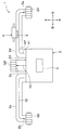
- the air conditioner 1 according to the present embodiment has a ventilation path AP through which conditioned air passes, and supplies conditioned air through the ventilation path AP.
- the air conditioner 1 is a vehicle air conditioner that is mounted on a vehicle and supplies conditioned air to the passenger compartment of the vehicle. Note that arrows f1 to f3 in FIG. 1 schematically show the flow of the conditioned air. In the drawings other than FIG. 4, the illustration of the voltage application unit 4ad is omitted.
- the air conditioner 1 includes a case 2, a blower 3, a cooler unit (not shown), a heater unit (not shown), an ozone generation unit 4, and an ozone removal unit 5.
- the blower 3, the cooler unit, the heater unit, the ozone generation unit 4, and the ozone removal unit 5 are disposed inside the case 2.
- the case 2 includes a ventilation path AP through which the conditioned air passes, an introduction port (not shown) for introducing outside air or inside air into the ventilation path AP, and three blowouts for blowing the conditioned air flowing through the ventilation path AP into the vehicle interior. Outlets 2a, 2b and 2c are formed. Outside air is air outside the vehicle compartment. The inside air is the air inside the passenger compartment of the vehicle.
- the air outlet 2a is an opening for blowing the conditioned air passing through the internal space of the duct 2d connected to the air outlet 2a (that is, a part of the ventilation path AP) from the grill G1 on the driver's seat side into the vehicle interior. It is.
- the air outlet 2b is an opening for blowing the conditioned air passing through the internal space of the duct 2e connected to the air outlet 2b (that is, a part of the ventilation path AP) from the passenger side grill G2 into the vehicle interior. It is.
- the air outlet 2c allows the conditioned air passing through the internal space of the duct 2f connected to the air outlet 2c (that is, a part of the ventilation path AP) to pass through the grill G3 located between the driver's seat and the passenger seat to the passenger compartment. It is an opening part for blowing out.
- the air conditioner 1 configured as described above introduces air into the ventilation path AP from the introduction port by the blower of the blower 3, cools it by the cooler unit, and in some cases, warms it by the heater unit, Supply cool or warm air into the passenger compartment. That is, all of the three ducts 2d to 2f are connected to the air outlets 2a to 2c for blowing the conditioned air toward the upper space in the vertical direction of the vehicle in the passenger compartment.
- the ducts 2d and 2e are so-called side face ducts.
- the ozone generator 4 is a device that generates ozone for purifying the conditioned air passing through the ventilation path AP.
- the ozone generation unit 4 has a configuration in which a plurality of ozone generation units 4 a shown in FIG. 3 are arranged.
- the ozone generator 4 has a total of 36 ozone generation units 4 a arranged in a rectangle of six vertically and six horizontally.
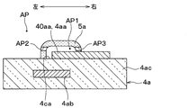
- each of the 36 ozone generation units 4a has a first electrode 4aa. Most of the first electrode 4aa is buried inside the dielectric substrate 4ac.
- the first electrode 4aa has five branch portions, and has a sub-electrode 40aa at the tip of each of the five branch portions.
- the first electrode 4aa has a plurality of sub-electrodes 40aa.
- each of the five sub electrodes 40aa is exposed to the outside of the dielectric substrate 4ac.
- each of the five sub electrodes 40aa is exposed to the purification space AP1.
- the purification space AP1 is a part of the ventilation path AP.
- Each of the plurality of sub-electrodes 40aa opposes a corresponding sub-removal portion 5a among a plurality of sub-removal portions 5a described later with a purification space AP1 interposed therebetween.
- Each of the 36 ozone generation units 4a includes a second electrode 4ab spaced from the first electrode 4aa and a dielectric substrate 4ac as shown in FIG.
- the first electrode 4aa and the second electrode 4ab are both made of a conductive material.
- the dielectric substrate 4ac is made of a dielectric material such as glass. As shown in FIG. 4, at least a part of the dielectric substrate 4ac is sandwiched between the first electrode 4aa and the second electrode 4ab.
- the ozone generation unit 4 includes a voltage application unit 4ad that applies a voltage between the first electrode 4aa and the second electrode 4ab in each of the 36 ozone generation units 4a.
- the voltage application unit 4ad generates ozone by applying a voltage between the first electrode 4aa and the second electrode 4ab to generate discharge.
- the ozone thus generated purifies the conditioned air passing through the ventilation path AP.
- the ozone generator 4 is configured such that the purification space AP1 is located above the center line in the vehicle vertical direction of the duct 2d in the internal space of the duct 2d. Yes.
- the ozone removing unit 5 is a member that removes ozone generated by the ozone generating unit 4 from the conditioned air. As shown in FIGS. 2 and 3, the ozone removing unit 5 includes a plurality of sub-removing units 5 a arranged corresponding to one body 1 on a plurality of sub-electrodes 40 aa.
- Each of the plurality of sub-removal units 5a is configured by a filter carrying activated carbon that decomposes ozone.
- the sub-removal unit 5a may be made of another material as long as it is a member that removes ozone from the conditioned air. That is, the sub-removal unit 5a may be configured of, for example, a filter supporting manganese dioxide that decomposes ozone, zeolite that adsorbs ozone, or silica gel.
- each of the plurality of sub-removal portions 5a has through-holes AP2, AP3, AP4, penetrating in a predetermined direction (that is, the horizontal direction in FIG. 4). It has a dome shape in which AP5 is formed. A space surrounded by the dome shape constitutes a purification space AP1. That is, each of the plurality of sub-removal portions 5a surrounds the purification space AP1.
- the through holes AP2, AP3, AP4, and AP5 are spaces that connect the purification space AP1 and a dome-shaped external space.
- the through holes AP2, AP3, AP4, and AP5 connect the purification space AP1 and the space on the opposite side of the ozone removal unit 5 to the purification space AP1 side in the ventilation path AP.
- the dome shape may be a hemispherical shape or a shape deviating from the hemispherical shape.
- the conditioned air flows in the left-right direction in FIG. 3 in the ventilation path AP. That is, the conditioned air flows from the through hole AP2 to the through hole AP3 or from the through hole AP3 to the through hole AP2.
- Each of the plurality of sub-removal portions 5a is disposed on the surface 4ca on the side where the first electrode 4aa is disposed in the corresponding dielectric substrate 4ac.
- the ozone removing unit 5 is disposed to face the sub electrode 40aa across the purification space AP1 that is a part of the ventilation path AP.
- the ozone removing unit 5 includes a plurality of sub-removing units 5a corresponding to the plurality of sub-electrodes 40aa on a one-to-one basis.
- the purification space AP1 is a part of the internal space of the duct 2d.
- each of the plurality of sub-removal portions 5a has one end of the first electrode 4aa in a direction parallel to the surface 4ca on the side where the sub-electrode 40aa is disposed in the dielectric substrate 4ac.
- the sub removal portion 5a is formed so that the purification space AP1 surrounds the entire surface of the sub electrode 40aa on the ventilation path AP side.
- the direction parallel to the surface 4ca is a direction parallel to the paper surface of FIGS. 5A and 5B.
- each of the 36 ozone generation units 4a is provided with one or more sub-removal units 5a. More specifically, one sub-removal portion 5a is provided corresponding to each of the plurality of sub-electrodes 40aa provided in the ozone generation unit 4a. Two or more sub-removal portions 5a may be provided corresponding to each of the plurality of sub-electrodes 40aa.
- the ozone removing unit 5 is configured such that the purification space AP1 is located above the center line in the vehicle vertical direction in the internal space of the duct 2d.
- the purification space AP1 extends along the direction in which the duct 2d extends (that is, the vehicle left-right direction) It is configured.
- the air conditioner 1 includes the ozone removing unit 5 that removes ozone from the conditioned air. And each of the some sub removal part 5a which comprises this ozone removal part 5 is arrange
- the conditioned air passing through the ventilation path AP can be purified (for example, deodorized, sterilized, etc.) by the ozone generated by the ozone generator 4.
- the ozone contained in the conditioned wind which passes along purification space AP1 is provided by providing the sub removal part 5a arrange
- each sub-removal portion 5a surrounds the purification space AP1 and has through holes AP2, AP3, AP4, and AP5.
- through-hole AP2, AP3, AP4, AP5 connects the space on the opposite side to purification
- the conditioned air introduced into the purification space AP1 from the through holes AP2, AP3, AP4, AP5 can be purified by ozone generated by the ozone generator 4. And in purification space AP1, ozone can be efficiently removed by the sub removal part 5a, and it can blow out from through-hole AP2, AP3, AP4, AP5.
- the corresponding sub-removal portion 5a is configured so that the purification space AP1 covers and surrounds the entire surface of the sub-electrode 40aa on the ventilation path AP side.
- the purification space AP1 is a space around each sub-removal portion 5a, and in particular, is a space sandwiched between sub-electrodes 40aa corresponding to each sub-removal portion 5a.
- the ozone generated around the sub electrode 40aa or the sub electrode 40aa can be more reliably removed by the sub removing unit 5a.
- the ozone removing unit 5 has a plurality of sub-removing units 5a corresponding to the plurality of sub-electrodes 40aa on a one-to-one basis.
- Each of the plurality of sub-electrodes 40aa is opposed to the corresponding sub-removal unit 5a among the plurality of sub-removal units 5a with the purification space AP1 interposed therebetween.
- ozone is surely easily removed from each of the plurality of sub-electrodes 40aa, and the influence on the occupant's human body and the like can be further alleviated.
- the air conditioner 1 is a vehicle air conditioner that is mounted on a vehicle and supplies conditioned air to the passenger compartment of the vehicle.
- ozone is suppressed from being transported to the passenger compartment or the like, and the influence on the human body of the occupant can be mitigated.
- the ventilation path AP is an internal space of the duct 2d connected to the air outlet 2a that blows the conditioned air toward the upper space in the vehicle vertical direction in the vehicle compartment.
- the air conditioner 1 it is possible to purify the conditioned air that goes to the upper body (for example, the face) of the passenger. Moreover, the ozone contained in the conditioned air that goes to the upper body (for example, the face) of the occupant can be reduced. Thereby, the air conditioner 1 which concerns on this embodiment contributes to alleviation of the influence on a passenger
- the ozone generation unit 4 and the ozone removal unit 5 are configured so that the purification space AP1 is positioned above the center line in the vehicle vertical direction of the duct 2d in the internal space of the duct 2d.
- water existing in the internal space of the duct 2d can be prevented from adhering to the ozone generation unit 4 (for example, the first electrode 4aa) or the ozone removal unit 5.
- the ozone generation unit 4 and the ozone removal unit 5 are configured such that the purification space AP1 extends along the direction in which the duct 2d extends (that is, the vehicle left-right direction).
- the ventilation resistance of the conditioned air passing through the vicinity of the ozone generating unit 4 and the ozone removing unit 5 is reduced, and a decrease in the wind speed of the conditioned air can be reduced.
- a filter carrying activated carbon or manganese dioxide is employed as one specific example of the sub-removal unit 5a.
- the ozone generation unit 4 and the ozone removal unit 5 are configured such that the purification space AP1 is positioned above the vehicle vertical direction in the internal space of the duct 2d.
- the ozone generation unit 4 and the ozone removal unit 5 are configured such that the purification space AP1 is positioned below the vehicle vertical direction in the internal space of the duct 2d. You may do it. In this case, a specific effect by arranging the ozone generation unit 4 and the ozone removal unit 5 on the upper side cannot be obtained, but the other effects described in the first embodiment can be obtained.
- the sub-removal part 5a is formed so that the purification space AP1 surrounds the entire surface of the sub-electrode 40aa on the ventilation path AP side.
- the sub-removal portion 5a may be formed so that the purification space AP1 surrounds a part of the surface of the sub-electrode 40aa on the ventilation path AP side. In this case, a specific effect obtained by forming the sub removal portion 5a so as to surround the entire surface of the sub electrode 40aa on the ventilation path AP side cannot be obtained, but other effects described in the first embodiment are not obtained. can get.
- a configuration may be adopted in which a plurality of devices each composed of the ozone generation unit 4 and the ozone removal unit 5 in the first embodiment are stacked. In this case, the effect of ozone purification and ozone removal can be particularly enhanced.
- the ozone generator 4 and the ozone remover 5 in the first embodiment are replaced with the evaporator 6 in the purification space AP1. It may be arranged on the upstream side of the flow of conditioned air. In this case, ozone purification by the ozone generator 4 can prevent the odor due to ozone from accumulating in the evaporator 6. Note that an arrow f4 in FIG. 9 schematically shows the flow of the conditioned air.
- the deodorizing filter 7 which is arrange
- the odor component adsorbed by the deodorizing filter 7 can be decomposed by ozone generated by the discharge of the first electrode 4aa. Thereby, the lifetime of the deodorizing filter 7 can be lengthened.
- an arrow f5 in FIG. 10 schematically shows the flow of the conditioned air.
- the ozone generator 4 and the ozone remover 5 in the first embodiment are arranged at the outlet 2 g for blowing conditioned air from the inside of the air conditioner 1 to the outside. You may do it.
- an air conditioner that supplies conditioned air that has passed through a ventilation path includes an ozone generator that generates ozone that purifies the conditioned air that passes through the ventilation path;
- An ozone removing unit that removes generated ozone from the conditioned air is provided.
- the ozone generator includes a first electrode, a second electrode spaced from the first electrode, and a voltage applying unit that generates ozone by applying a voltage between the first electrode and the second electrode.
- the ozone removal part is arrange
- the ozone removing unit surrounds the purification space and has a through hole. And a through-hole connects the space on the opposite side to the purification
- the conditioned air introduced into the space surrounded by the dome shape from the through hole can be purified by the ozone generated by the ozone generator. And, in the space surrounded by the dome shape, ozone can be efficiently removed by the ozone removing unit and can be blown out from the through hole.
- an ozone removal part makes the purification space surround the whole surface by the side of a ventilation passage among the 1st electrodes. Is formed.
- ozone generated around the first electrode or the first electrode can be more reliably removed by the ozone removing unit.
- the first electrode has a plurality of sub-electrodes.
- the ozone removing unit has a plurality of sub-removing units corresponding to the plurality of sub-electrodes on a one-to-one basis. Each of the plurality of sub-electrodes is opposed to the corresponding sub-removal portion among the plurality of sub-removal portions with a purification space interposed therebetween.
- ozone is surely easily removed from each of the plurality of sub-electrodes, and the influence on the human body of the occupant can be further alleviated.
- the air conditioner in the air conditioner according to any one of the first to fourth aspects, is mounted on a vehicle, and the vehicle interior of the vehicle is air-conditioned. It is a vehicle air conditioner that supplies wind.
- the ozone is suppressed from being transported into the passenger compartment and the like, and the influence on the human body of the occupant can be mitigated.
- the ventilation space blows out the conditioned air toward the upper space in the up-down direction of the vehicle in the passenger compartment. It is a part of the internal space of the duct connected to the air outlet.
- the sixth aspect it is possible to purify the conditioned air that goes to the upper body (for example, the face) of the passenger. Moreover, the ozone contained in the conditioned air that goes to the upper body (for example, the face) of the occupant can be reduced. This particularly contributes to mitigating the impact on the human body.
- a purification space is provided above the center line in the vehicle vertical direction of the duct in the internal space of the duct.
- the ozone generation unit and the ozone removal unit are configured to be positioned.
- the seventh aspect it is possible to prevent water existing in the internal space of the duct from adhering to the ozone generating part (for example, the first electrode) or the ozone removing part.
- the ozone generation unit and the ozone removal unit have a ventilation space extending in the direction of the duct. It is comprised so that it may extend along.
- the airflow resistance of the conditioned air passing through the vicinity of the ozone generating unit and the ozone removing unit is reduced, and the decrease in the wind speed of the conditioned air can be reduced.
- the vehicle air conditioner includes an evaporator for cooling the conditioned air.
- generation part is arrange
- the ninth aspect it is possible to prevent odors and the like due to ozone from accumulating in the evaporator by the purification of ozone by the ozone generator.
- the ozone removing unit is a filter supporting activated carbon or manganese dioxide.
- the air conditioner in any one viewpoint of 1st thru
- a deodorizing filter is provided.
- the odor component adsorbed on the deodorizing filter can be decomposed by ozone generated by the discharge of the first electrode. Thereby, the lifetime of a deodorizing filter can be lengthened.
Landscapes
- Engineering & Computer Science (AREA)
- Mechanical Engineering (AREA)
- Chemical & Material Sciences (AREA)
- Combustion & Propulsion (AREA)
- General Engineering & Computer Science (AREA)
- Air-Conditioning For Vehicles (AREA)
- Air Filters, Heat-Exchange Apparatuses, And Housings Of Air-Conditioning Units (AREA)
- Disinfection, Sterilisation Or Deodorisation Of Air (AREA)
Abstract
Appareil de climatisation, qui apporte de l'air conditionné à travers un passage d'air (AP), est pourvu d'une unité de production d'ozone (4) qui produit de l'ozone pour purifier l'air climatisé traversant le passage d'air, et une unité d'élimination d'ozone (5) qui élimine l'ozone produit à partir de l'air climatisé. L'unité de production d'ozone comporte une première électrode (4aa), une seconde électrode (4ab) séparée de la première électrode, et une unité d'application de tension (4ad) qui amène l'ozone à être produit par l'application d'une tension entre la première électrode et la seconde électrode. L'unité d'élimination d'ozone est disposée en regard de la première électrode depuis l'autre côté d'un espace de purification (AP1), qui fait partie du passage d'air.
Applications Claiming Priority (2)
| Application Number | Priority Date | Filing Date | Title |
|---|---|---|---|
| JP2016203666A JP2019214217A (ja) | 2016-10-17 | 2016-10-17 | 空調装置 |
| JP2016-203666 | 2016-10-17 |
Publications (1)
| Publication Number | Publication Date |
|---|---|
| WO2018074061A1 true WO2018074061A1 (fr) | 2018-04-26 |
Family
ID=62019615
Family Applications (1)
| Application Number | Title | Priority Date | Filing Date |
|---|---|---|---|
| PCT/JP2017/030418 Ceased WO2018074061A1 (fr) | 2016-10-17 | 2017-08-24 | Appareil de climatisation |
Country Status (2)
| Country | Link |
|---|---|
| JP (1) | JP2019214217A (fr) |
| WO (1) | WO2018074061A1 (fr) |
Citations (4)
| Publication number | Priority date | Publication date | Assignee | Title |
|---|---|---|---|---|
| JPS5076739A (fr) * | 1973-11-07 | 1975-06-23 | ||
| JPH07305883A (ja) * | 1994-05-11 | 1995-11-21 | Matsushita Refrig Co Ltd | 加湿装置 |
| JPH10138753A (ja) * | 1996-11-14 | 1998-05-26 | Zexel Corp | 車両用空気清浄装置 |
| JP2007112219A (ja) * | 2005-10-18 | 2007-05-10 | Denso Corp | 車両用屋上装着型空調装置 |
-
2016
- 2016-10-17 JP JP2016203666A patent/JP2019214217A/ja active Pending
-
2017
- 2017-08-24 WO PCT/JP2017/030418 patent/WO2018074061A1/fr not_active Ceased
Patent Citations (4)
| Publication number | Priority date | Publication date | Assignee | Title |
|---|---|---|---|---|
| JPS5076739A (fr) * | 1973-11-07 | 1975-06-23 | ||
| JPH07305883A (ja) * | 1994-05-11 | 1995-11-21 | Matsushita Refrig Co Ltd | 加湿装置 |
| JPH10138753A (ja) * | 1996-11-14 | 1998-05-26 | Zexel Corp | 車両用空気清浄装置 |
| JP2007112219A (ja) * | 2005-10-18 | 2007-05-10 | Denso Corp | 車両用屋上装着型空調装置 |
Also Published As
| Publication number | Publication date |
|---|---|
| JP2019214217A (ja) | 2019-12-19 |
Similar Documents
| Publication | Publication Date | Title |
|---|---|---|
| JP4470710B2 (ja) | 車両用空気調和装置 | |
| US10240808B2 (en) | Induced air discharging unit | |
| JP2008260520A (ja) | 車両用空調システム | |
| EP4023471A1 (fr) | Module de conduit et siège de véhicule comprenant le module de conduit | |
| KR101762804B1 (ko) | 차량의 공기조화 시스템 | |
| JP2010006177A (ja) | 車両用静電霧化装置 | |
| CN204641330U (zh) | 专车专用汽车空气净化器 | |
| JP2010504244A (ja) | 車室用空気浄化装置 | |
| JP4492602B2 (ja) | 車両用静電霧化装置 | |
| WO2018074061A1 (fr) | Appareil de climatisation | |
| JP4881181B2 (ja) | 車両用浄化装置 | |
| JP2008207633A5 (fr) | ||
| JP4258422B2 (ja) | 換気設備 | |
| WO2007049989A1 (fr) | Systeme de ventilation et de climatisation destine a une voiture de chemins de fer | |
| KR100685728B1 (ko) | 자동차용 광촉매 공기 정화기 | |
| JP7625402B2 (ja) | 鉄道車両の空気浄化装置 | |
| KR20070071571A (ko) | 음/양이온 발생기를 구비한 자동차용 공조장치 | |
| KR101391154B1 (ko) | 차량용 이온발생장치 | |
| CN215474366U (zh) | 一种具有空气净化装置的汽车空调出风口 | |
| KR20150033712A (ko) | 공기 조화기 | |
| KR101384560B1 (ko) | 차량용 공조장치 | |
| US8500890B2 (en) | Air channel with integrated odor absorbing element | |
| JP2002362143A (ja) | 車両用香り発生装置 | |
| JP2007021100A (ja) | 空気清浄機 | |
| JP2010042750A (ja) | 車両用空調装置 |
Legal Events
| Date | Code | Title | Description |
|---|---|---|---|
| 121 | Ep: the epo has been informed by wipo that ep was designated in this application |
Ref document number: 17863130 Country of ref document: EP Kind code of ref document: A1 |
|
| NENP | Non-entry into the national phase |
Ref country code: DE |
|
| 122 | Ep: pct application non-entry in european phase |
Ref document number: 17863130 Country of ref document: EP Kind code of ref document: A1 |
|
| NENP | Non-entry into the national phase |
Ref country code: JP |