WO2018074191A1 - 真空ポンプ及び該真空ポンプに適用される防水構造、制御装置 - Google Patents
真空ポンプ及び該真空ポンプに適用される防水構造、制御装置 Download PDFInfo
- Publication number
- WO2018074191A1 WO2018074191A1 PCT/JP2017/035473 JP2017035473W WO2018074191A1 WO 2018074191 A1 WO2018074191 A1 WO 2018074191A1 JP 2017035473 W JP2017035473 W JP 2017035473W WO 2018074191 A1 WO2018074191 A1 WO 2018074191A1
- Authority
- WO
- WIPO (PCT)
- Prior art keywords
- control device
- vacuum pump
- base portion
- gap
- cover
- Prior art date
- Legal status (The legal status is an assumption and is not a legal conclusion. Google has not performed a legal analysis and makes no representation as to the accuracy of the status listed.)
- Ceased
Links
Images



Classifications
-
- F—MECHANICAL ENGINEERING; LIGHTING; HEATING; WEAPONS; BLASTING
- F04—POSITIVE - DISPLACEMENT MACHINES FOR LIQUIDS; PUMPS FOR LIQUIDS OR ELASTIC FLUIDS
- F04D—NON-POSITIVE-DISPLACEMENT PUMPS
- F04D19/00—Axial-flow pumps
- F04D19/02—Multi-stage pumps
- F04D19/04—Multi-stage pumps specially adapted to the production of a high vacuum, e.g. molecular pumps
- F04D19/042—Turbomolecular vacuum pumps
-
- F—MECHANICAL ENGINEERING; LIGHTING; HEATING; WEAPONS; BLASTING
- F04—POSITIVE - DISPLACEMENT MACHINES FOR LIQUIDS; PUMPS FOR LIQUIDS OR ELASTIC FLUIDS
- F04D—NON-POSITIVE-DISPLACEMENT PUMPS
- F04D25/00—Pumping installations or systems
- F04D25/02—Units comprising pumps and their driving means
- F04D25/06—Units comprising pumps and their driving means the pump being electrically driven
- F04D25/068—Mechanical details of the pump control unit
-
- F—MECHANICAL ENGINEERING; LIGHTING; HEATING; WEAPONS; BLASTING
- F04—POSITIVE - DISPLACEMENT MACHINES FOR LIQUIDS; PUMPS FOR LIQUIDS OR ELASTIC FLUIDS
- F04B—POSITIVE-DISPLACEMENT MACHINES FOR LIQUIDS; PUMPS
- F04B37/00—Pumps having pertinent characteristics not provided for in, or of interest apart from, groups F04B25/00 - F04B35/00
- F04B37/10—Pumps having pertinent characteristics not provided for in, or of interest apart from, groups F04B25/00 - F04B35/00 for special use
- F04B37/14—Pumps having pertinent characteristics not provided for in, or of interest apart from, groups F04B25/00 - F04B35/00 for special use to obtain high vacuum
-
- F—MECHANICAL ENGINEERING; LIGHTING; HEATING; WEAPONS; BLASTING
- F04—POSITIVE - DISPLACEMENT MACHINES FOR LIQUIDS; PUMPS FOR LIQUIDS OR ELASTIC FLUIDS
- F04B—POSITIVE-DISPLACEMENT MACHINES FOR LIQUIDS; PUMPS
- F04B37/00—Pumps having pertinent characteristics not provided for in, or of interest apart from, groups F04B25/00 - F04B35/00
- F04B37/10—Pumps having pertinent characteristics not provided for in, or of interest apart from, groups F04B25/00 - F04B35/00 for special use
- F04B37/14—Pumps having pertinent characteristics not provided for in, or of interest apart from, groups F04B25/00 - F04B35/00 for special use to obtain high vacuum
- F04B37/16—Means for nullifying unswept space
-
- F—MECHANICAL ENGINEERING; LIGHTING; HEATING; WEAPONS; BLASTING
- F04—POSITIVE - DISPLACEMENT MACHINES FOR LIQUIDS; PUMPS FOR LIQUIDS OR ELASTIC FLUIDS
- F04B—POSITIVE-DISPLACEMENT MACHINES FOR LIQUIDS; PUMPS
- F04B39/00—Component parts, details, or accessories, of pumps or pumping systems specially adapted for elastic fluids, not otherwise provided for in, or of interest apart from, groups F04B25/00 - F04B37/00
-
- F—MECHANICAL ENGINEERING; LIGHTING; HEATING; WEAPONS; BLASTING
- F04—POSITIVE - DISPLACEMENT MACHINES FOR LIQUIDS; PUMPS FOR LIQUIDS OR ELASTIC FLUIDS
- F04D—NON-POSITIVE-DISPLACEMENT PUMPS
- F04D17/00—Radial-flow pumps, e.g. centrifugal pumps; Helico-centrifugal pumps
- F04D17/08—Centrifugal pumps
- F04D17/16—Centrifugal pumps for displacing without appreciable compression
- F04D17/168—Pumps specially adapted to produce a vacuum
-
- F—MECHANICAL ENGINEERING; LIGHTING; HEATING; WEAPONS; BLASTING
- F04—POSITIVE - DISPLACEMENT MACHINES FOR LIQUIDS; PUMPS FOR LIQUIDS OR ELASTIC FLUIDS
- F04D—NON-POSITIVE-DISPLACEMENT PUMPS
- F04D19/00—Axial-flow pumps
- F04D19/02—Multi-stage pumps
- F04D19/04—Multi-stage pumps specially adapted to the production of a high vacuum, e.g. molecular pumps
-
- F—MECHANICAL ENGINEERING; LIGHTING; HEATING; WEAPONS; BLASTING
- F04—POSITIVE - DISPLACEMENT MACHINES FOR LIQUIDS; PUMPS FOR LIQUIDS OR ELASTIC FLUIDS
- F04D—NON-POSITIVE-DISPLACEMENT PUMPS
- F04D25/00—Pumping installations or systems
- F04D25/02—Units comprising pumps and their driving means
- F04D25/06—Units comprising pumps and their driving means the pump being electrically driven
- F04D25/0693—Details or arrangements of the wiring
-
- F—MECHANICAL ENGINEERING; LIGHTING; HEATING; WEAPONS; BLASTING
- F04—POSITIVE - DISPLACEMENT MACHINES FOR LIQUIDS; PUMPS FOR LIQUIDS OR ELASTIC FLUIDS
- F04D—NON-POSITIVE-DISPLACEMENT PUMPS
- F04D29/00—Details, component parts, or accessories
- F04D29/08—Sealings
- F04D29/083—Sealings especially adapted for elastic fluid pumps
-
- F—MECHANICAL ENGINEERING; LIGHTING; HEATING; WEAPONS; BLASTING
- F04—POSITIVE - DISPLACEMENT MACHINES FOR LIQUIDS; PUMPS FOR LIQUIDS OR ELASTIC FLUIDS
- F04D—NON-POSITIVE-DISPLACEMENT PUMPS
- F04D29/00—Details, component parts, or accessories
- F04D29/40—Casings; Connections of working fluid
- F04D29/52—Casings; Connections of working fluid for axial pumps
- F04D29/522—Casings; Connections of working fluid for axial pumps especially adapted for elastic fluid pumps
-
- H—ELECTRICITY
- H01—ELECTRIC ELEMENTS
- H01R—ELECTRICALLY-CONDUCTIVE CONNECTIONS; STRUCTURAL ASSOCIATIONS OF A PLURALITY OF MUTUALLY-INSULATED ELECTRICAL CONNECTING ELEMENTS; COUPLING DEVICES; CURRENT COLLECTORS
- H01R13/00—Details of coupling devices of the kinds covered by groups H01R12/70 or H01R24/00 - H01R33/00
- H01R13/46—Bases; Cases
- H01R13/52—Dustproof, splashproof, drip-proof, waterproof, or flameproof cases
-
- F—MECHANICAL ENGINEERING; LIGHTING; HEATING; WEAPONS; BLASTING
- F04—POSITIVE - DISPLACEMENT MACHINES FOR LIQUIDS; PUMPS FOR LIQUIDS OR ELASTIC FLUIDS
- F04D—NON-POSITIVE-DISPLACEMENT PUMPS
- F04D19/00—Axial-flow pumps
- F04D19/02—Multi-stage pumps
- F04D19/04—Multi-stage pumps specially adapted to the production of a high vacuum, e.g. molecular pumps
- F04D19/048—Multi-stage pumps specially adapted to the production of a high vacuum, e.g. molecular pumps comprising magnetic bearings
-
- F—MECHANICAL ENGINEERING; LIGHTING; HEATING; WEAPONS; BLASTING
- F04—POSITIVE - DISPLACEMENT MACHINES FOR LIQUIDS; PUMPS FOR LIQUIDS OR ELASTIC FLUIDS
- F04D—NON-POSITIVE-DISPLACEMENT PUMPS
- F04D29/00—Details, component parts, or accessories
- F04D29/58—Cooling; Heating; Diminishing heat transfer
- F04D29/582—Cooling; Heating; Diminishing heat transfer specially adapted for elastic fluid pumps
- F04D29/5853—Cooling; Heating; Diminishing heat transfer specially adapted for elastic fluid pumps heat insulation or conduction
-
- F—MECHANICAL ENGINEERING; LIGHTING; HEATING; WEAPONS; BLASTING
- F05—INDEXING SCHEMES RELATING TO ENGINES OR PUMPS IN VARIOUS SUBCLASSES OF CLASSES F01-F04
- F05D—INDEXING SCHEME FOR ASPECTS RELATING TO NON-POSITIVE-DISPLACEMENT MACHINES OR ENGINES, GAS-TURBINES OR JET-PROPULSION PLANTS
- F05D2210/00—Working fluids
- F05D2210/10—Kind or type
- F05D2210/12—Kind or type gaseous, i.e. compressible
-
- F—MECHANICAL ENGINEERING; LIGHTING; HEATING; WEAPONS; BLASTING
- F05—INDEXING SCHEMES RELATING TO ENGINES OR PUMPS IN VARIOUS SUBCLASSES OF CLASSES F01-F04
- F05D—INDEXING SCHEME FOR ASPECTS RELATING TO NON-POSITIVE-DISPLACEMENT MACHINES OR ENGINES, GAS-TURBINES OR JET-PROPULSION PLANTS
- F05D2240/00—Components
- F05D2240/55—Seals
Definitions
- the present invention relates to a vacuum pump and a waterproof structure and a control device applied to the vacuum pump, and in particular, improves the efficiency of maintenance work on site and when the cover is removed at the time of circuit separation, etc.
- the present invention relates to a vacuum pump that prevents water from entering, a waterproof structure applied to the vacuum pump, and a control device.
- a vacuum pump is generally used for evacuating the chamber.
- a turbo molecular pump which is one of the vacuum pumps, is used frequently from the viewpoints of particularly low residual gas and easy maintenance.
- the turbo molecular pump not only evacuates the chamber, but also exhausts these process gases from the chamber. Also used.
- the turbo molecular pump includes a pump body and a control device that controls the pump body.
- the pump body and the control device are usually connected by a cable and a connector plug mechanism.
- a structure that allows the pump body and the control device to be detachable in the axial direction of the pump as in Patent Document 1 has been proposed. Are known.
- the empty space around the pump body integrated with the control device is narrow.
- the slight gap between the pump body and the control device can be used to align the position of the terminal on the pump body side and the terminal on the control device side. It was necessary for the worker to check the attachment / detachment of the terminal while looking into the terminal, and it was difficult to align and maintenance work was not easy.
- a water cooling pipe which will be described later, is disposed in the pump body. Due to the cooling of the pump main body by the water cooling pipe, water droplets such as condensation may be generated around the pump main body. When the pump main body and the control device are separated, there is a risk that the water droplets may enter the connector connecting portion from the periphery of the pump main body.
- An object of the present invention is to provide a vacuum pump to prevent, a waterproof structure applied to the vacuum pump, and a control device.
- the present invention is a vacuum pump having a waterproof structure in which a control device is detachably attached to a base portion of a pump body, and the waterproof structure is a side portion of the base portion.
- a connector portion disposed between the base portion and the control device via an electrical cable, a wall portion projecting from the base portion and the control device around the connector portion, and the wall And a wall cover covering the part.
- the connector is arranged on the side of the base part, the pump body and the control device can be easily attached and detached even if there is not enough space in the axial direction of the pump.
- a wall portion projects from the side of the base portion and the control device so as to straddle the base portion and the control device. For this reason, even when the cover is removed during maintenance work, the intrusion of water droplets can be prevented by this wall portion. Thereby, the safety of the circuit at the time of maintenance work can be achieved.
- the present invention is an invention of a vacuum pump, comprising a gap formed between the base portion and the control device, and a gap cover portion covering an outer periphery of the gap is provided on the wall portion cover. It is arranged on the inner side.
- the gap cover portion may be configured integrally with the cover or may be configured separately.
- the present invention is an invention of a vacuum pump, comprising a gap formed between the base portion and the control device, wherein the outer peripheral surface of the control device is disposed on the base portion side of the pump body. It is characterized by covering the outer periphery of the gap by projecting it.
- the outer peripheral surface forming the control device is projected in the axial direction of the pump.
- the present invention is an invention of a vacuum pump, comprising a gap formed between the base portion and the control device, wherein one end of the upper surface of the control device is connected to the base portion of the pump body.
- a bent piece is provided on the side, and the outer periphery of the gap is covered with the bent piece.
- the present invention is an invention of a vacuum pump, characterized in that a seal member for preventing water from entering the gap is provided.
- the present invention is an invention of a vacuum pump, characterized in that a groove or a hole for drainage is formed on the upper surface of the wall portion or the control device.
- the present invention is an invention of a vacuum pump, characterized in that the wall cover is formed so as to fit the outer shape of the base part and the control device.
- the present invention is an invention of a waterproof structure, and is characterized by being arranged in the vacuum pump according to any one of Claims 1 to 7.
- the vacuum pump has a large number of cables and is easily bulky, but by installing the waterproof structure, maintenance work can be easily performed from the side of the pump.
- the present invention is an invention of a control device, which is applied to the vacuum pump according to any one of Claims 1 to 7, and moves in a radial direction with respect to the pump body. It is detachable.
- the connector is disposed on the side portion of the base portion, and the wall portion is formed around the connector so as to straddle the base portion and the control device. Even if there is not enough space in the axial direction, the pump body and the control device can be easily attached and detached. In addition, even when the cover is removed during maintenance work, the intrusion of water droplets can be prevented by the wall portion. Thereby, the safety of the circuit at the time of maintenance work can be achieved.
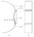
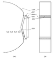
- Configuration diagram of the first embodiment of the present invention Longitudinal sectional view around the base and control unit Front view of base unit and control unit including cover Horizontal sectional view taken along line AA in FIG. Diagram showing the procedure for maintenance work Longitudinal sectional view around the base and control unit (different form) Longitudinal sectional view around the base and control unit (different form) Configuration diagram of second embodiment of the present invention The figure which shows another form of 2nd Embodiment
- FIG. 1 shows a configuration diagram of the first embodiment of the present invention.
- a turbo molecular pump 10 includes a pump body 100 and a control device 200 that are integrated.
- An intake port 101 is formed at the upper end of the cylindrical outer cylinder 127 of the pump body 100.
- a rotating body 103 On the inner side of the outer cylinder 127, there is provided a rotating body 103 in which a plurality of rotating blades 102a, 102b, 102c,... By turbine blades for sucking and exhausting gas are formed radially and in multiple stages.
- a rotor shaft 113 is attached to the center of the rotating body 103, and the rotor shaft 113 is levitated and supported in the air by a so-called 5-axis control magnetic bearing.
- the upper radial electromagnet 104 is configured such that four electromagnets are paired with an X axis and a Y axis that are the radial coordinate axes of the rotor shaft 113 and are orthogonal to each other.
- An upper radial sensor 107 composed of four electromagnets is provided adjacent to and corresponding to the upper radial electromagnet 104.
- the upper radial sensor 107 is configured to detect a radial displacement of the rotating body 103 and send it to the control device 200.
- excitation of the upper radial electromagnet 104 is controlled through a compensation circuit having a PID adjustment function based on the displacement signal detected by the upper radial sensor 107, and the upper radial position of the rotor shaft 113 is determined. adjust.
- the rotor shaft 113 is formed of a high permeability material (such as iron) and is attracted by the magnetic force of the upper radial electromagnet 104. Such adjustment is performed independently in the X-axis direction and the Y-axis direction.
- the lower radial electromagnet 105 and the lower radial sensor 108 are arranged in the same manner as the upper radial electromagnet 104 and the upper radial sensor 107, and the lower radial position of the rotor shaft 113 is set to the upper radial position. It is adjusted in the same way.
- axial electromagnets 106A and 106B are arranged with a disk-shaped metal disk 111 provided at the lower part of the rotor shaft 113 sandwiched up and down.
- the metal disk 111 is made of a high permeability material such as iron.
- An axial sensor 109 is provided to detect the axial displacement of the rotor shaft 113, and the axial displacement signal is sent to the control device 200.
- the excitation of the axial electromagnets 106A and 106B is controlled via a compensation circuit having a PID adjustment function of the control device 200 based on the axial displacement signal.
- the axial electromagnet 106A and the axial electromagnet 106B attract the metal disk 111 upward and downward by magnetic force.
- control device 200 appropriately adjusts the magnetic force exerted on the metal disk 111 by the axial electromagnets 106A and 106B, and causes the rotor shaft 113 to magnetically float in the axial direction and hold the space in a non-contact manner. ing.
- the motor 121 includes a plurality of magnetic poles arranged circumferentially so as to surround the rotor shaft 113. Each magnetic pole is controlled by the control device 200 so as to rotationally drive the rotor shaft 113 through electromagnetic force acting between the rotor shaft 113 and the magnetic pole.
- a plurality of stationary blades 123a, 123b, 123c,... are arranged with a small gap from the rotor blades 102a, 102b, 102c,.
- the rotor blades 102a, 102b, 102c,... are each inclined at a predetermined angle from a plane perpendicular to the axis of the rotor shaft 113 in order to transfer exhaust gas molecules downward by collision.
- the fixed blades 123 are also formed so as to be inclined at a predetermined angle from a plane perpendicular to the axis of the rotor shaft 113, and are arranged alternately with the stages of the rotary blades 102 toward the inside of the outer cylinder 127. ing. And one end of the fixed wing
- the fixed blade spacer 125 is a ring-shaped member, and is made of, for example, a metal such as aluminum, iron, stainless steel, copper, or an alloy containing these metals as a component.
- the outer cylinder 127 is fixed to the outer periphery of the fixed blade spacer 125 with a slight gap.
- a base portion 129 is disposed at the bottom of the outer cylinder 127, and a threaded spacer 131 is disposed between the lower portion of the fixed blade spacer 125 and the base portion 129.
- An exhaust port 133 is formed below the threaded spacer 131 in the base portion 129 and communicates with the outside.
- the threaded spacer 131 is a cylindrical member made of metal such as aluminum, copper, stainless steel, iron, or an alloy containing these metals as a component, and a plurality of spiral thread grooves 131a are formed on the inner peripheral surface thereof. It is marked.
- the direction of the spiral of the thread groove 131 a is a direction in which molecules of the exhaust gas move toward the exhaust port 133 when the molecules of the exhaust gas move in the rotation direction of the rotating body 103.
- a rotating blade 102d is suspended from the lowermost part of the rotating body 103 following the rotating blades 102a, 102b, 102c.
- the outer peripheral surface of the rotary blade 102d is cylindrical and projects toward the inner peripheral surface of the threaded spacer 131, and is close to the inner peripheral surface of the threaded spacer 131 with a predetermined gap. Yes.
- the base portion 129 is a disk-like member that constitutes the base portion of the turbo molecular pump 10, and is generally made of a metal such as iron, aluminum, or stainless steel.
- the base part 129 physically holds the turbo molecular pump 10 and also has a function of a heat conduction path, a metal having rigidity such as iron, aluminum and copper and high thermal conductivity is used. Is desirable.
- Exhaust gas sucked from the intake port 101 passes between the rotary blade 102 and the fixed blade 123 and is transferred to the base portion 129. At this time, the temperature of the rotor blades 102 increases due to frictional heat generated when the exhaust gas contacts or collides with the rotor blades 102, conduction or radiation of heat generated by the motor 121, etc. It is transmitted to the fixed wing 123 side by conduction with gas molecules of the exhaust gas.
- the fixed blade spacers 125 are joined to each other at the outer peripheral portion, and heat received by the fixed blade 123 from the rotor blade 102, frictional heat generated when exhaust gas contacts or collides with the fixed blade 123, and the like are used for the outer cylinder 127 and the screw. This is transmitted to the attached spacer 131.
- the exhaust gas transferred to the threaded spacer 131 is sent to the exhaust port 133 while being guided by the screw groove 131a.
- the process gas may be introduced into the chamber at a high temperature in order to increase the reactivity.
- These process gases become solid when cooled and reach a certain temperature, and the product may be deposited in the exhaust system.
- this type of process gas becomes a low temperature in the turbo molecular pump 10 and becomes a solid, and adheres to and accumulates in the turbo molecular pump 10.
- the product described above was in a state where it was easily solidified and adhered in a portion where the temperature near the exhaust port was low, particularly in the vicinity of the rotary blade 102d and the threaded spacer 131.
- a heater or an annular water-cooled tube (not shown) is wound around the outer periphery of the base portion 129, and a temperature sensor (eg, a thermistor) (not shown) is embedded in the base portion 129, for example. Based on this signal, the heating of the heater and the cooling by the water cooling pipe are controlled so as to keep the temperature of the base portion 129 at a constant high temperature (set temperature).
- FIG. 2 a wall portion 202 protrudes from the side of the base portion 129 and the control device 200 in a circumferential shape.
- the wall cover 201 is detachable so as to cover and fit the wall 202.
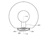
- FIG. 3 is a front view of the base portion 129 including the wall portion cover 201 and the control device 200
- FIG. 4 is a horizontal sectional view taken along line AA in FIG.
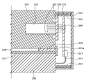
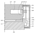
- FIG. 2 is a longitudinal sectional view around the base portion 129 and the control device 200 taken along the arrow BB in FIG.
- a space 203 is formed in the base portion 129 for wiring such as a magnetic bearing and a motor in the pump main body 100.
- the inside of the space 203 is a vacuum atmosphere, while the control device 200 and the connection portion with the control device 200 are an air atmosphere.
- a hermetic connector 205 is attached to the wall around the right end of the space 203. Between the hermetic connector 205 and the base portion 129, an O-ring (not shown) is disposed in an O-ring groove 207.
- a number of pins 209 are passed through the hermetic connector 205. The right end of the pin 209 is exposed and passes through a small hole (not shown) of the relay substrate 211.
- a pin 209 is soldered to the relay board 211 for connection with the control device 200 at a small hole portion of the relay board 211.
- a terminal 213 is disposed at the lower end of the relay board 211 so that one end of the harness 215 is detachable.
- the other end of the harness 215 extends into the control device 200.
- a control cable and a power cable (not shown) are connected to the left end of the pin 209 and are passed through the space 203.
- a lid 217 is disposed on the upper part of the casing forming the control device 200.
- a gap 210 of about 1 mm is formed between the base portion 129 and the control device 200 for heat insulation.
- An annular or belt-like seal member 219 is provided on the outer peripheral side of the gap 210 so that water droplets do not enter the inside.
- the gap cover portion 201 a is in contact with the base portion 129 and the control device 200 so as to cover the seal member 219 and the right end of the lid 217.
- the gap cover portion 201 a is provided so as to protrude along the gap 210 inside the cover.
- the gap cover portion 201a may be configured separately from the lid 217 and the casing of the control device 200, or may be configured integrally with the lid 217 and the casing of the control device 200 as described later.
- the wall cover 201 is formed in a curved shape in accordance with the outer shape of the base portion 129 and the control device 200. However, when the pump is square, it is desirable to match the shape of the pump formed in a flat shape. Further, as shown in FIG. 3, the wall cover 201 is formed such that the circumference on the base portion 129 side is short and the circumference on the control device 200 side is long due to the routing of the wiring.
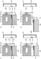
- FIG. 5A the wall cover 201 is removed from the base portion 129 and the side portion of the control device 200 when performing maintenance work.
- FIG. 5B the harness 215 is removed from the terminal 213.
- FIG.5 (d) the housing
- the pump main body 100 and the control device 200 can be easily attached and detached even if there is no sufficient space in the axial direction of the vacuum pump.
- the maintenance work of the control device 200 can be easily performed even when the pump body 100 is attached to a chamber (not shown). Since the terminals are arranged on the sides of the vacuum pump, it is easy to see by removing the wall cover 201, and the harness 215 can be easily attached to and detached from the terminals 213.
- a function for preventing water droplets and the like from entering the connector connecting portion when performing maintenance work will be described. Condensation may occur around the base portion 129 due to cooling by the water-cooled tube. In addition, water drops may leak from the water-cooled tube during maintenance.
- a wall 202 is projected from the side of the base portion 129 and the control device 200 so as to extend over the base portion 129 and the control device 200. For this reason, even when the wall cover 201 is removed during maintenance work, the wall 202 can prevent water droplets from entering. Further, a seal member 219 and a lid 217 are inserted into the gap 210. For this reason, it is difficult for water droplets to enter the gap 210.
- the gap cover portion 201 a is in contact with the base portion 129 and the control device 200 so as to cover the seal member 219 and the right end of the lid 217. For this reason, the penetration
- the sealing member 219 is provided in this way, the wall portion 202 may be separated into the base portion 129 side and the control device 200 side.
- a notch for taking out the cable to the outside may be formed in a part of the wall portion 202.
- the wall portion on the base portion 129 side is a U-shaped wall having a wall and protruding walls on both sides.
- the wall portion on the control device 200 side can be partially cut out at a location where the seal member 219 is provided.
- the side surface of the casing that forms the control device 200 that faces the relay substrate 211 projects the protruding portion 200a toward the upper part in the axial direction to the extent that it covers the thickness of the lid 217 and the seal member 219. This makes it difficult for water droplets to enter the gap 210 as in FIG. Thereby, the safety of the circuit at the time of maintenance work can be achieved.
- the right end of the lid 217 is bent in an L shape up to a range covering the thickness of the seal member 219 to form a bent piece 217a. This also makes it difficult for water droplets to enter the gap 210. Thereby, the safety of the circuit at the time of maintenance work can be achieved.
- FIG. 8A is a plan view when the cover of the base portion is removed
- FIG. 8B is a side view of the base portion.
- a wall portion 222 is provided around the hermetic connector 205 (not shown).
- a wall cover 201 (not shown) is detachable so as to cover and fit the wall 222.
- a groove 223 is formed on the outer periphery of the wall portion 222, and a water droplet 225 flows along the groove 223.
- the wall 222 may have a quadrilateral or round shape other than the triangle as long as the water droplet 225 flows along the groove 223.
- FIG. 9 shows another form of the second embodiment.
- 9A is a plan view when the cover of the base portion is removed
- FIG. 9B is a side view of the base portion.
- a wall portion 232 protrudes around a hermetic connector 205 (not shown).
- a wall cover 201 (not shown) is detachable so as to cover and fit the wall 232.
- a groove 235 is formed on the upper surface of the wall portion 232, and a water droplet 225 flows along the groove 235.
- the groove 235 is connected to the hole 237, and this hole 237 serves as an entrance of the through hole 239.
- the water droplet 225 passing through the groove 235 falls through the through hole 239.
Landscapes
- Engineering & Computer Science (AREA)
- Mechanical Engineering (AREA)
- General Engineering & Computer Science (AREA)
- Non-Positive Displacement Air Blowers (AREA)
- Compressor (AREA)
- Compressors, Vaccum Pumps And Other Relevant Systems (AREA)
- Structures Of Non-Positive Displacement Pumps (AREA)
Abstract
【課題】現場での保守作業の効率を上げ、かつ、回路分離時等でカバーを外した際に、コネクタ接続部への水の侵入を防止する真空ポンプ及び該真空ポンプに適用される防水構造、制御装置を提供する。 【解決手段】 保守作業を行う際には制御装置200の筐体を数十ミリ程度下げてから、制御装置200の筐体をポンプの径方向に引き出す。このため、真空ポンプの軸方向には十分な空きスペースが無くても容易にポンプ本体100と制御装置200の着脱が行える。ベース部129及び制御装置200の側部には壁部202が周状に突設されている。このため、保守作業の際に壁部カバー201を取り外した場合であってもこの壁部202により水滴の侵入を防ぐことができる。更に、隙間210にはシール部材219と蓋217が挿入されている。このため、この隙間210には水滴が侵入し難い。
Description
本発明は真空ポンプ及び該真空ポンプに適用される防水構造、制御装置に係わり、特に現場での保守作業の効率を上げ、かつ、回路分離時等でカバーを外した際に、コネクタ接続部への水の侵入を防止する真空ポンプ及び該真空ポンプに適用される防水構造、制御装置に関する。
近年のエレクトロニクスの発展に伴い、メモリや集積回路といった半導体の需要が急激に増大している。
これらの半導体は、きわめて純度の高い半導体基板に不純物をドープして電気的性質を与えたり、エッチングにより半導体基板上に微細な回路を形成したりなどして製造される。
これらの半導体は、きわめて純度の高い半導体基板に不純物をドープして電気的性質を与えたり、エッチングにより半導体基板上に微細な回路を形成したりなどして製造される。
そして、これらの作業は空気中の塵等による影響を避けるため高真空状態のチャンバ内で行われる必要がある。このチャンバの排気には、一般に真空ポンプが用いられているが、特に残留ガスが少なく、保守が容易等の点から真空ポンプの中の一つであるターボ分子ポンプが多用されている。
また、半導体の製造工程では、さまざまなプロセスガスを半導体の基板に作用させる工程が数多くあり、ターボ分子ポンプはチャンバ内を真空にするのみならず、これらのプロセスガスをチャンバ内から排気するのにも使用される。
このターボ分子ポンプは、ポンプ本体とそのポンプ本体を制御する制御装置とからなる。
ポンプ本体と制御装置との間は、通常、ケーブルとコネクタプラグ機構とで接続される。このポンプ本体と制御装置間のケーブルの接続ミスやケーブルの長さ調整の煩雑さを回避するため、従来特許文献1のようにポンプ本体と制御装置をポンプの軸方向に着脱自在にできる構造が知られている。
ポンプ本体と制御装置との間は、通常、ケーブルとコネクタプラグ機構とで接続される。このポンプ本体と制御装置間のケーブルの接続ミスやケーブルの長さ調整の煩雑さを回避するため、従来特許文献1のようにポンプ本体と制御装置をポンプの軸方向に着脱自在にできる構造が知られている。
ところで、一般的にはこのように一体化されたポンプ本体と制御装置周りの空きスペースは狭い。特に軸方向にはスペース的な余裕の無いことが多い。このため、保守の際には一体化されたポンプ本体と制御装置を一旦チャンバから外し、作業スペースの十分に取れる場所までポンプ本体と制御装置を一体化させたまま移動してから保守を行う必要があった。
また、このようにポンプ本体底部で軸方向に端子の配設されている場合、ポンプ本体側の端子と制御装置側の端子の位置を合わせるのにはポンプ本体と制御装置間のわずかの隙間から作業員が端子の箇所を覗きつつ端子の着脱を確認する必要があり、位置合わせするのが難しく保守作業が簡単ではなかった。
更に、ポンプ本体には後述する水冷管が配設されている。この水冷管によるポンプ本体の冷却により、ポンプ本体の周囲に結露等の水滴が生じることがある。そして、ポンプ本体と制御装置の分離の際には、この水滴がポンプ本体の周囲よりコネクタ接続部へ侵入する恐れがあった。
本発明はこのような従来の課題に鑑みてなされたもので、現場での保守作業の効率を上げ、かつ、回路分離時等でカバーを外した際に、コネクタ接続部への水の侵入を防止する真空ポンプ及び該真空ポンプに適用される防水構造、制御装置を提供することを目的とする。
このため本発明(請求項1)は、ポンプ本体のベース部に対し制御装置が着脱自在に配設され、防水構造を備えた真空ポンプであって、前記防水構造は、前記ベース部の側部に配設され、該ベース部と前記制御装置間を電気的ケーブルを介して結ぶコネクタ部と、該コネクタ部の周囲に前記ベース部と前記制御装置をまたがり突設された壁部と、該壁部を覆う壁部カバーとを備えて構成した。
コネクタがベース部の側部に配設されているので、ポンプの軸方向には十分な空きスペースが無くても容易にポンプ本体と制御装置の着脱が行える。ベース部及び制御装置の側部には壁部がベース部及び制御装置にまたがり周状に突設されている。このため、保守作業の際にカバーを取り外した場合であってもこの壁部により水滴の侵入を防ぐことができる。これにより、保守作業時における回路の安全が図れる。
また、本発明(請求項2)は真空ポンプの発明であって、前記ベース部と前記制御装置の間に形成された隙間を備え、該隙間の外周を覆う隙間カバー部が前記壁部カバーの内側に配設されたことを特徴とする。
このことにより、隙間を伝って流れる水滴の侵入をより一層厳格に防ぐことができる。これにより、保守作業時における回路の安全がより確実に図れる。隙間カバー部はカバーに対して一体として構成されてもよいし、別体で構成されることも可能である。
更に、本発明(請求項3)は真空ポンプの発明であって、前記ベース部と前記制御装置の間に形成された隙間を備え、前記制御装置の外周面を前記ポンプ本体の前記ベース部側に突設させることで前記隙間の外周を覆うことを特徴とする。
制御装置を形成する外周面をポンプの軸方向に突設させる。この突設部分により隙間の外周を覆うことで、隙間にはより一層水滴が侵入し難くなる。これにより、保守作業時における回路の安全がより一層確実に図れる。
更に、本発明(請求項4)は真空ポンプの発明であって、前記ベース部と前記制御装置の間に形成された隙間を備え、前記制御装置の上面の一端を前記ポンプ本体の前記ベース部側に折り曲げた折曲片を備え、該折曲片により前記隙間の外周を覆うことを特徴とする。
制御装置の上面の一端を折り曲げて折曲片を形成する。この折曲片により隙間の外周を覆うことで、隙間にはより一層水滴が侵入し難くなる。これにより、保守作業時における回路の安全がより一層確実に図れる。
更に、本発明(請求項5)は真空ポンプの発明であって、前記隙間に対し水の浸入を防ぐためのシール部材が配設されたことを特徴とする。
隙間に対しシール部材が挿入されたことで、この隙間には水滴が侵入し難い。
更に、本発明(請求項6)は真空ポンプの発明であって、前記壁部又は前記制御装置の前記上面に排水のための溝若しくは穴が形成されたことを特徴とする。
壁部に水滴の通る溝若しくは穴を形成したことで、カバーを外したときでも水滴はこの溝若しくは穴に沿って流れるため内側に侵入することはない。これにより、保守作業時における回路の安全が図れる。
更に、本発明(請求項7)は真空ポンプの発明であって、前記壁部カバーが前記ベース部と前記制御装置の外形に合うように形成されたことを特徴とする。
このことにより、ポンプ周りに邪魔な出っ張りは無くなり保守作業がし易く、美観にも優れる。
更に、本発明(請求項8)は防水構造の発明であって、請求項1~7のいずれか1項に記載の真空ポンプに配置されたことを特徴とする。
真空ポンプはケーブルの本数が多く嵩張り易いが、上記防水構造を搭載することでポンプの側部から容易に保守作業が行える。
更に、本発明(請求項9)は制御装置の発明であって、請求項1~7のいずれか1項に記載の真空ポンプに適用され、前記ポンプ本体に対して径方向に移動することで着脱自在であることを特徴とする。
制御装置を径方向に移動自在としたことでポンプの軸方向に作業スペースが十分に取れない所でも容易に保守作業が行える。
以上説明したように本発明(請求項1)によれば、ベース部の側部にコネクタを配設し、このコネクタの周囲にベース部と制御装置とをまたがり壁部を形成したので、ポンプの軸方向には十分な空きスペースが無くても容易にポンプ本体と制御装置の着脱が行える。
また、保守作業の際にカバーを取り外した場合であっても壁部により水滴の侵入を防ぐことができる。これにより、保守作業時における回路の安全が図れる。
また、保守作業の際にカバーを取り外した場合であっても壁部により水滴の侵入を防ぐことができる。これにより、保守作業時における回路の安全が図れる。
以下、本発明の第1実施形態について説明する。本発明の第1実施形態の構成図を図1に示す。図1において、ターボ分子ポンプ10は、ポンプ本体100と制御装置200とが一体化されている。
ポンプ本体100の円筒状の外筒127の上端には吸気口101が形成されている。外筒127の内方には、ガスを吸引排気するためのタービンブレードによる複数の回転翼102a、102b、102c・・・を周部に放射状かつ多段に形成した回転体103を備える。
この回転体103の中心にはロータ軸113が取り付けられており、このロータ軸113は、例えば、いわゆる5軸制御の磁気軸受により空中に浮上支持かつ位置制御されている。
上側径方向電磁石104は、4個の電磁石が、ロータ軸113の径方向の座標軸であって互いに直交するX軸とY軸とに対をなして配置されている。この上側径方向電磁石104に近接かつ対応されて4個の電磁石からなる上側径方向センサ107が備えられている。この上側径方向センサ107は回転体103の径方向変位を検出し、制御装置200に送るように構成されている。
制御装置200においては、上側径方向センサ107が検出した変位信号に基づき、PID調節機能を有する補償回路を介して上側径方向電磁石104の励磁を制御し、ロータ軸113の上側の径方向位置を調整する。
ロータ軸113は、高透磁率材(鉄など)などにより形成され、上側径方向電磁石104の磁力により吸引されるようになっている。かかる調整は、X軸方向とY軸方向とにそれぞれ独立して行われる。
また、下側径方向電磁石105及び下側径方向センサ108が、上側径方向電磁石104及び上側径方向センサ107と同様に配置され、ロータ軸113の下側の径方向位置を上側の径方向位置と同様に調整している。
更に、軸方向電磁石106A、106Bが、ロータ軸113の下部に備えた円板状の金属ディスク111を上下に挟んで配置されている。金属ディスク111は、鉄などの高透磁率材で構成されている。ロータ軸113の軸方向変位を検出するために軸方向センサ109が備えられ、その軸方向変位信号が制御装置200に送られるように構成されている。
そして、軸方向電磁石106A、106Bは、この軸方向変位信号に基づき制御装置200のPID調節機能を有する補償回路を介して励磁制御されるようになっている。軸方向電磁石106Aと軸方向電磁石106Bは、磁力により金属ディスク111をそれぞれ上方と下方とに吸引する。
このように、制御装置200は、この軸方向電磁石106A、106Bが金属ディスク111に及ぼす磁力を適当に調節し、ロータ軸113を軸方向に磁気浮上させ、空間に非接触で保持するようになっている。
モータ121は、ロータ軸113を取り囲むように周状に配置された複数の磁極を備えている。各磁極は、ロータ軸113との間に作用する電磁力を介してロータ軸113を回転駆動するように、制御装置200によって制御されている。
回転翼102a、102b、102c・・・とわずかの空隙を隔てて複数枚の固定翼123a、123b、123c・・・が配設されている。回転翼102a、102b、102c・・・は、それぞれ排気ガスの分子を衝突により下方向に移送するため、ロータ軸113の軸線に垂直な平面から所定の角度だけ傾斜して形成されている。
また、固定翼123も、同様にロータ軸113の軸線に垂直な平面から所定の角度だけ傾斜して形成され、かつ外筒127の内方に向けて回転翼102の段と互い違いに配設されている。
そして、固定翼123の一端は、複数の段積みされた固定翼スペーサ125a、125b、125c・・・の間に嵌挿された状態で支持されている。
そして、固定翼123の一端は、複数の段積みされた固定翼スペーサ125a、125b、125c・・・の間に嵌挿された状態で支持されている。
固定翼スペーサ125はリング状の部材であり、例えばアルミニウム、鉄、ステンレス、銅などの金属、又はこれらの金属を成分として含む合金などの金属によって構成されている。
固定翼スペーサ125の外周には、わずかの空隙を隔てて外筒127が固定されている。外筒127の底部にはベース部129が配設され、固定翼スペーサ125の下部とベース部129の間にはネジ付きスペーサ131が配設されている。そして、ベース部129中のネジ付きスペーサ131の下部には排気口133が形成され、外部に連通されている。
ネジ付きスペーサ131は、アルミニウム、銅、ステンレス、鉄、又はこれらの金属を成分とする合金などの金属によって構成された円筒状の部材であり、その内周面に螺旋状のネジ溝131aが複数条刻設されている。
ネジ溝131aの螺旋の方向は、回転体103の回転方向に排気ガスの分子が移動したときに、この分子が排気口133の方へ移送される方向である。
ネジ溝131aの螺旋の方向は、回転体103の回転方向に排気ガスの分子が移動したときに、この分子が排気口133の方へ移送される方向である。
回転体103の回転翼102a、102b、102c・・・に続く最下部には回転翼102dが垂下されている。この回転翼102dの外周面は、円筒状で、かつネジ付きスペーサ131の内周面に向かって張り出されており、このネジ付きスペーサ131の内周面と所定の隙間を隔てて近接されている。
ベース部129は、ターボ分子ポンプ10の基底部を構成する円盤状の部材であり、一般には鉄、アルミニウム、ステンレスなどの金属によって構成されている。
ベース部129はターボ分子ポンプ10を物理的に保持すると共に、熱の伝導路の機能も兼ね備えているので、鉄、アルミニウムや銅などの剛性があり、熱伝導率も高い金属が使用されるのが望ましい。
かかる構成において、回転翼102がモータ121により駆動されてロータ軸113と共に回転すると、回転翼102と固定翼123の作用により、吸気口101を通じてチャンバからの排気ガスが吸気される。
吸気口101から吸気された排気ガスは、回転翼102と固定翼123の間を通り、ベース部129へ移送される。このとき、排気ガスが回転翼102に接触又は衝突する際に生ずる摩擦熱や、モータ121で発生した熱の伝導や輻射などにより、回転翼102の温度は上昇するが、この熱は、輻射又は排気ガスの気体分子等による伝導により固定翼123側に伝達される。
固定翼スペーサ125は、外周部で互いに接合しており、固定翼123が回転翼102から受け取った熱や排気ガスが固定翼123に接触又は衝突する際に生ずる摩擦熱などを外筒127やネジ付きスペーサ131へと伝達する。
ネジ付きスペーサ131に移送されてきた排気ガスは、ネジ溝131aに案内されつつ排気口133へと送られる。
ネジ付きスペーサ131に移送されてきた排気ガスは、ネジ溝131aに案内されつつ排気口133へと送られる。
ところで、プロセスガスは、反応性を高めるため高温の状態でチャンバに導入される場合がある。そして、これらのプロセスガスは、排気される際に冷却されてある温度になると固体となり排気系に生成物を析出する場合がある。
そして、この種のプロセスガスがターボ分子ポンプ10内で低温となって固体状となり、ターボ分子ポンプ10内部に付着して堆積する場合がある。
そして、この種のプロセスガスがターボ分子ポンプ10内で低温となって固体状となり、ターボ分子ポンプ10内部に付着して堆積する場合がある。
ターボ分子ポンプ10内部にプロセスガスの析出物が堆積すると、この堆積物がポンプ流路を狭め、ターボ分子ポンプ10の性能を低下させる原因となる。
ここに、前述した生成物は排気口付近の温度が低い部分、特に回転翼102d及びネジ付きスペーサ131付近で凝固、付着し易い状況にあった。この問題を解決するために、従来はベース部129等の外周に図示しないヒータや環状の水冷管を巻着させ、かつ例えばベース部129に図示しない温度センサ(例えばサーミスタ)を埋め込み、この温度センサの信号に基づきベース部129の温度を一定の高い温度(設定温度)に保つようにヒータの加熱や水冷管による冷却の制御が行われている。
次に、ポンプ本体100と制御装置200間で制御ケーブル、電源ケーブルを接続する端子周りの構造について説明する。
図2において、ベース部129及び制御装置200の側部には壁部202が周状に突設されている。そして、この壁部202を覆い嵌合するように壁部カバー201が着脱自在になっている。この壁部カバー201を含むベース部129と制御装置200の正面図を図3に、図3中の矢視線A-Aによる水平断面図を図4に示す。また、図2は、図4中の矢視線B-Bによるベース部129及び制御装置200周りの縦断面図を示している。
図2において、ベース部129及び制御装置200の側部には壁部202が周状に突設されている。そして、この壁部202を覆い嵌合するように壁部カバー201が着脱自在になっている。この壁部カバー201を含むベース部129と制御装置200の正面図を図3に、図3中の矢視線A-Aによる水平断面図を図4に示す。また、図2は、図4中の矢視線B-Bによるベース部129及び制御装置200周りの縦断面図を示している。
ベース部129内にはポンプ本体100内の磁気軸受やモータ等の配線用に空間203が形成されている。この空間203内は真空雰囲気であり、一方、制御装置200や制御装置200との接続部は大気雰囲気である。
そして、この空間203の右端周りの壁部にはハーメチックコネクタ205が取り付けられている。このハーメチックコネクタ205とベース部129の間には図示しないOリングがOリング用の溝207に配設されている。ハーメチックコネクタ205には多数のピン209が貫通されている。ピン209の右端は露出され、中継基板211の図示しない小穴を貫通している。制御装置200との接続のための中継基板211に対してピン209は中継基板211の小穴部分でハンダ付けされている。
そして、この空間203の右端周りの壁部にはハーメチックコネクタ205が取り付けられている。このハーメチックコネクタ205とベース部129の間には図示しないOリングがOリング用の溝207に配設されている。ハーメチックコネクタ205には多数のピン209が貫通されている。ピン209の右端は露出され、中継基板211の図示しない小穴を貫通している。制御装置200との接続のための中継基板211に対してピン209は中継基板211の小穴部分でハンダ付けされている。
中継基板211の下端には端子213が配設され、ハーネス215の一端が着脱自在なようになっている。ハーネス215の他端は制御装置200内部に延びている。一方、ピン209の左端には図示しない制御ケーブルや電源ケーブルが接続され、空間203の内部に通されている。
制御装置200を形成する筐体の上部には蓋217が配設されている。ベース部129と制御装置200の間には断熱のため1mm程度の隙間210が形成されている。この隙間210には水滴が内部に侵入しないように外周側に環状若しくは帯状のシール部材219が間装されている。そして、このシール部材219と蓋217の右端を覆うように隙間カバー部201aがベース部129と制御装置200に対して当接されている。この隙間カバー部201aは隙間210に沿ってカバーの内側において突設されたものである。隙間カバー部201aは、蓋217や制御装置200の筐体部と別体として構成されても良いし、後述するように蓋217や制御装置200の筐体部と一体として構成されても良い。
図4に示す通り、壁部カバー201はベース部129及び制御装置200の外形に合わせて曲面状に形成されている。但し、ポンプが角形の場合には平面状に形成される等ポンプの形状に合わせるのが望ましい。また、この壁部カバー201は図3に示す通り、配線の引き回しの関係でベース部129側の周長が短く、制御装置200側の周長が長く形成されている。
次に、本発明の第1実施形態の作用を説明する。
まず、保守作業を行う際の手順について図5に基づき説明する。図5(a)に示すように、保守作業を行う際にはベース部129及び制御装置200の側部より壁部カバー201を外す。図5(b)ではハーネス215を端子213から外す。次に、図5(c)では図示しないベース部129及び制御装置200間を締結していたボルトを取り外し、制御装置200の筐体を数十ミリ程度下げる。次に図5(d)に示すように、制御装置200の筐体をポンプの径方向に引き出す。
まず、保守作業を行う際の手順について図5に基づき説明する。図5(a)に示すように、保守作業を行う際にはベース部129及び制御装置200の側部より壁部カバー201を外す。図5(b)ではハーネス215を端子213から外す。次に、図5(c)では図示しないベース部129及び制御装置200間を締結していたボルトを取り外し、制御装置200の筐体を数十ミリ程度下げる。次に図5(d)に示すように、制御装置200の筐体をポンプの径方向に引き出す。
このことにより、真空ポンプの軸方向には十分な空きスペースが無くても容易にポンプ本体100と制御装置200の着脱が行える。この場合には、ポンプ本体100を図示しないチャンバに取り付けた状態であっても制御装置200の保守作業が容易に行える。真空ポンプの側部に端子が配置されているので壁部カバー201を外すことで見易く、ハーネス215の端子213への着脱も容易である。
次に、保守作業を行う際に、水滴等がコネクタ接続部へ侵入するのを防止する機能について説明する。
水冷管による冷却により、ベース部129の周囲には結露を生じている場合がある。また、保守の際には水冷管から水滴が漏れる恐れもある。これに対し、図2に示すように、ベース部129及び制御装置200の側部には壁部202がベース部129及び制御装置200にまたがり周状に突設されている。このため、保守作業の際に壁部カバー201を取り外した場合であってもこの壁部202により水滴の侵入を防ぐことができる。更に、隙間210にはシール部材219と蓋217が挿入されている。このため、この隙間210には水滴が侵入し難い。
水冷管による冷却により、ベース部129の周囲には結露を生じている場合がある。また、保守の際には水冷管から水滴が漏れる恐れもある。これに対し、図2に示すように、ベース部129及び制御装置200の側部には壁部202がベース部129及び制御装置200にまたがり周状に突設されている。このため、保守作業の際に壁部カバー201を取り外した場合であってもこの壁部202により水滴の侵入を防ぐことができる。更に、隙間210にはシール部材219と蓋217が挿入されている。このため、この隙間210には水滴が侵入し難い。
また、シール部材219と蓋217の右端を覆うように隙間カバー部201aがベース部129と制御装置200に対して当接されている。このため、隙間210を伝って流れる水滴の侵入をより一層厳格に防ぐことができる。これにより、保守作業時における回路の安全が確実に図れる。
なお、このようにシール部材219を配設した場合には、壁部202はベース部129側と制御装置200側とに分離されてもよい。また、壁部202の一部にはケーブルを外部に出すための切欠きが形成されてもよい。この場合、ベース部129側の壁部は庇と両側に壁を突設したコの字状の壁とするのが望ましい。制御装置200側の壁部はシール部材219の設けられている箇所に一部切欠きを設けることができる。
なお、このようにシール部材219を配設した場合には、壁部202はベース部129側と制御装置200側とに分離されてもよい。また、壁部202の一部にはケーブルを外部に出すための切欠きが形成されてもよい。この場合、ベース部129側の壁部は庇と両側に壁を突設したコの字状の壁とするのが望ましい。制御装置200側の壁部はシール部材219の設けられている箇所に一部切欠きを設けることができる。
図2の隙間カバー部201aに代えて図6に示すように構成されてもよい。即ち、制御装置200を形成する筐体の中継基板211に対峙する側の側面は、蓋217及びシール部材219の厚みを覆う範囲まで突設部200aを軸方向上部に向けて突設させる。このことにより、図2と同様に隙間210には水滴が侵入し難くなる。これにより、保守作業時における回路の安全が図れる。
また、図2の隙間カバー部201aに代えて図7に示すように構成されてもよい。即ち、蓋217の右端はシール部材219の厚みを覆う範囲までL字状に折曲げられ折曲片217aが形成されている。このことによっても同様に隙間210には水滴が侵入し難くなる。これにより、保守作業時における回路の安全が図れる。
次に、本発明の第2実施形態について説明する。
本発明の第2実施形態は、壁部に対し溝及び穴を形成することにより水滴を誘導し制御装置200より排水する構造である。図8(a)はベース部のカバーを取ったときの平面図、図8(b)はベース部の側面図を示す。図8において、図示しないハーメチックコネクタ205周りには壁部222が突設されている。そして、この壁部222を覆い嵌合するように図示しない壁部カバー201が着脱自在になっている。壁部222の外周には溝223が形成されており、水滴225がこの溝223に沿って流れるようになっている。
本発明の第2実施形態は、壁部に対し溝及び穴を形成することにより水滴を誘導し制御装置200より排水する構造である。図8(a)はベース部のカバーを取ったときの平面図、図8(b)はベース部の側面図を示す。図8において、図示しないハーメチックコネクタ205周りには壁部222が突設されている。そして、この壁部222を覆い嵌合するように図示しない壁部カバー201が着脱自在になっている。壁部222の外周には溝223が形成されており、水滴225がこの溝223に沿って流れるようになっている。
かかる構成において、壁部カバー201を外したときでも水滴225はこの溝223に沿って流れるため内側に侵入することはない。これにより、保守作業時における回路の安全が図れる。なお、壁部222の形状は水滴225が溝223に沿って流れる構造であれば、三角形以外にも四角形や丸形等であってもよい。
また、第2実施形態の別形態を図9に示す。図9(a)はベース部のカバーを取ったときの平面図、図9(b)はベース部の側面図を示す。図9において、図示しないハーメチックコネクタ205周りには壁部232が突設されている。そして、この壁部232を覆い嵌合するように図示しない壁部カバー201が着脱自在になっている。壁部232の上面には溝235が形成されており、水滴225がこの溝235に沿って流れるようになっている。溝235は穴237と連結しており、この穴237は通孔239の入り口になっている。溝235を通った水滴225は通孔239を通り落下する。
かかる構成において、壁部カバー201を外したときでも水滴225は溝235、穴237及び通孔239を流れるため内側に侵入することはない。これにより、保守作業時における回路の安全が図れる。
なお、本発明の実施形態及び各変形例は、必要に応じて組み合わせる構成にしてもよい。また、本発明は、本発明の精神を逸脱しない限り種々の改変をなすことができ、そして、本発明が当該改変されたものにも及ぶことは当然である。
10 ターボ分子ポンプ
100 ポンプ本体
129 ベース部
200 制御装置
200a 突設部
201 壁部カバー
201a 隙間カバー部
202、222、232 壁部
205 ハーメチックコネクタ
210 隙間
211 中継基板
213 端子
215 ハーネス
217 蓋
217a 折曲片
219 シール部材
223、235 溝
225 水滴
237 穴
239 通孔
100 ポンプ本体
129 ベース部
200 制御装置
200a 突設部
201 壁部カバー
201a 隙間カバー部
202、222、232 壁部
205 ハーメチックコネクタ
210 隙間
211 中継基板
213 端子
215 ハーネス
217 蓋
217a 折曲片
219 シール部材
223、235 溝
225 水滴
237 穴
239 通孔
Claims (9)
- ポンプ本体のベース部に対し制御装置が着脱自在に配設され、防水構造を備えた真空ポンプであって、
前記防水構造は、
前記ベース部の側部に配設され、該ベース部と前記制御装置間を電気的ケーブルを介して結ぶコネクタ部と、
該コネクタ部の周囲に前記ベース部と前記制御装置をまたがり突設された壁部と、
該壁部を覆う壁部カバーとを備えたことを特徴とする真空ポンプ。 - 前記ベース部と前記制御装置の間に形成された隙間を備え、
該隙間の外周を覆う隙間カバー部が前記壁部カバーの内側に配設されたことを特徴とする請求項1記載の真空ポンプ。 - 前記ベース部と前記制御装置の間に形成された隙間を備え、
前記制御装置の外周面を前記ポンプ本体の前記ベース部側に突設させることで前記隙間の外周を覆うことを特徴とする請求項1記載の真空ポンプ。 - 前記ベース部と前記制御装置の間に形成された隙間を備え、
前記制御装置の上面の一端を前記ポンプ本体の前記ベース部側に折り曲げた折曲片を備え、
該折曲片により前記隙間の外周を覆うことを特徴とする請求項1記載の真空ポンプ。 - 前記隙間に対し水の浸入を防ぐためのシール部材が配設されたことを特徴とする請求項2~4のいずれか1項に記載の真空ポンプ。
- 前記壁部又は前記制御装置の前記上面に排水のための溝若しくは穴が形成されたことを特徴とする請求項1~5のいずれか1項に記載の真空ポンプ。
- 前記壁部カバーが前記ベース部と前記制御装置の外形に合うように形成されたことを特徴とする請求項1~6のいずれか1項に記載の真空ポンプ。
- 請求項1~7のいずれか1項に記載の真空ポンプに配置されたことを特徴とする防水構造。
- 請求項1~7のいずれか1項に記載の真空ポンプに適用され、前記ポンプ本体に対して径方向に移動することで着脱自在であることを特徴とする制御装置。
Priority Applications (4)
| Application Number | Priority Date | Filing Date | Title |
|---|---|---|---|
| KR1020197009447A KR102430356B1 (ko) | 2016-10-21 | 2017-09-29 | 진공 펌프 및 그 진공 펌프에 적용되는 방수 구조, 제어장치 |
| EP17861978.9A EP3530952B1 (en) | 2016-10-21 | 2017-09-29 | Vacuum pump |
| CN201780062788.0A CN109790846B (zh) | 2016-10-21 | 2017-09-29 | 真空泵及应用于该真空泵的防水构造、控制装置 |
| US16/341,495 US11215187B2 (en) | 2016-10-21 | 2017-09-29 | Vacuum pump, and waterproof structure and control apparatus applied to vacuum pump |
Applications Claiming Priority (2)
| Application Number | Priority Date | Filing Date | Title |
|---|---|---|---|
| JP2016-207396 | 2016-10-21 | ||
| JP2016207396A JP6753759B2 (ja) | 2016-10-21 | 2016-10-21 | 真空ポンプ及び該真空ポンプに適用される防水構造、制御装置 |
Publications (1)
| Publication Number | Publication Date |
|---|---|
| WO2018074191A1 true WO2018074191A1 (ja) | 2018-04-26 |
Family
ID=62019339
Family Applications (1)
| Application Number | Title | Priority Date | Filing Date |
|---|---|---|---|
| PCT/JP2017/035473 Ceased WO2018074191A1 (ja) | 2016-10-21 | 2017-09-29 | 真空ポンプ及び該真空ポンプに適用される防水構造、制御装置 |
Country Status (6)
| Country | Link |
|---|---|
| US (1) | US11215187B2 (ja) |
| EP (1) | EP3530952B1 (ja) |
| JP (1) | JP6753759B2 (ja) |
| KR (1) | KR102430356B1 (ja) |
| CN (1) | CN109790846B (ja) |
| WO (1) | WO2018074191A1 (ja) |
Cited By (2)
| Publication number | Priority date | Publication date | Assignee | Title |
|---|---|---|---|---|
| CN109578341A (zh) * | 2018-11-30 | 2019-04-05 | 江苏维尔特泵业有限公司 | 一种热水泵用轴承箱水冷却装置 |
| US20220170470A1 (en) * | 2019-03-28 | 2022-06-02 | Edwards Japan Limited | Vacuum pump and control apparatus of vacuum pump |
Families Citing this family (3)
| Publication number | Priority date | Publication date | Assignee | Title |
|---|---|---|---|---|
| JP6912196B2 (ja) * | 2016-12-28 | 2021-08-04 | エドワーズ株式会社 | 真空ポンプ及び該真空ポンプに適用されるコネクタ、制御装置 |
| JP7124787B2 (ja) * | 2019-04-17 | 2022-08-24 | 株式会社島津製作所 | 電源一体型真空ポンプ |
| JP7533324B2 (ja) * | 2021-04-01 | 2024-08-14 | 株式会社島津製作所 | 真空ポンプ |
Citations (4)
| Publication number | Priority date | Publication date | Assignee | Title |
|---|---|---|---|---|
| JPS63315024A (ja) * | 1988-06-02 | 1988-12-22 | Olympus Optical Co Ltd | 内視鏡 |
| JPH0729631A (ja) * | 1993-07-12 | 1995-01-31 | Sumitomo Wiring Syst Ltd | 電気自動車の充電用コネクタ回りの排水構造 |
| JPH11173293A (ja) | 1997-12-10 | 1999-06-29 | Ebara Corp | ターボ分子ポンプ装置 |
| JP2016079906A (ja) * | 2014-10-17 | 2016-05-16 | 株式会社島津製作所 | 真空ポンプ |
Family Cites Families (17)
| Publication number | Priority date | Publication date | Assignee | Title |
|---|---|---|---|---|
| US5458496A (en) | 1993-07-12 | 1995-10-17 | Sumitomo Wiring Systems, Ltd. | Charge coupling for electric vehicle |
| IT1288737B1 (it) * | 1996-10-08 | 1998-09-24 | Varian Spa | Dispositivo di pompaggio da vuoto. |
| JP2002276587A (ja) * | 2001-03-19 | 2002-09-25 | Boc Edwards Technologies Ltd | ターボ分子ポンプ |
| CN101713397B (zh) * | 2003-12-30 | 2014-07-09 | 艾默生环境优化技术有限公司 | 压缩机保护和诊断系统 |
| JP2006344503A (ja) * | 2005-06-09 | 2006-12-21 | Boc Edwards Kk | 端子構造及び真空ポンプ |
| DE102006016405B4 (de) | 2006-04-07 | 2024-08-01 | Pfeiffer Vacuum Gmbh | Vakuumpumpe mit Antriebsgerät |
| DE102006036493A1 (de) * | 2006-08-04 | 2008-02-21 | Oerlikon Leybold Vacuum Gmbh | Vakuumpumpe |
| DE202007012070U1 (de) * | 2007-08-30 | 2009-01-08 | Oerlikon Leybold Vacuum Gmbh | Stromdurchführung einer Vakuumpumpe |
| JP3138105U (ja) | 2007-10-09 | 2007-12-20 | 株式会社島津製作所 | ターボ分子ポンプ |
| JP4659811B2 (ja) | 2007-10-29 | 2011-03-30 | 株式会社荏原製作所 | 回転装置 |
| JP5218220B2 (ja) * | 2009-03-31 | 2013-06-26 | 株式会社島津製作所 | ターボ分子ポンプ装置およびその制御装置 |
| JP5545358B2 (ja) * | 2010-03-11 | 2014-07-09 | 株式会社島津製作所 | ターボ分子ポンプ装置 |
| JP5353838B2 (ja) * | 2010-07-07 | 2013-11-27 | 株式会社島津製作所 | 真空ポンプ |
| US20130209272A1 (en) * | 2010-10-07 | 2013-08-15 | Edwards Limited | Vacuum pump control device and vacuum pump |
| CN103228923B (zh) * | 2010-10-19 | 2016-09-21 | 埃地沃兹日本有限公司 | 真空泵 |
| DE102013213815A1 (de) * | 2013-07-15 | 2015-01-15 | Pfeiffer Vacuum Gmbh | Vakuumpumpe |
| JP6735526B2 (ja) * | 2013-08-30 | 2020-08-05 | エドワーズ株式会社 | 真空ポンプ |
-
2016
- 2016-10-21 JP JP2016207396A patent/JP6753759B2/ja active Active
-
2017
- 2017-09-29 US US16/341,495 patent/US11215187B2/en not_active Expired - Fee Related
- 2017-09-29 WO PCT/JP2017/035473 patent/WO2018074191A1/ja not_active Ceased
- 2017-09-29 EP EP17861978.9A patent/EP3530952B1/en active Active
- 2017-09-29 KR KR1020197009447A patent/KR102430356B1/ko active Active
- 2017-09-29 CN CN201780062788.0A patent/CN109790846B/zh active Active
Patent Citations (4)
| Publication number | Priority date | Publication date | Assignee | Title |
|---|---|---|---|---|
| JPS63315024A (ja) * | 1988-06-02 | 1988-12-22 | Olympus Optical Co Ltd | 内視鏡 |
| JPH0729631A (ja) * | 1993-07-12 | 1995-01-31 | Sumitomo Wiring Syst Ltd | 電気自動車の充電用コネクタ回りの排水構造 |
| JPH11173293A (ja) | 1997-12-10 | 1999-06-29 | Ebara Corp | ターボ分子ポンプ装置 |
| JP2016079906A (ja) * | 2014-10-17 | 2016-05-16 | 株式会社島津製作所 | 真空ポンプ |
Non-Patent Citations (1)
| Title |
|---|
| See also references of EP3530952A4 |
Cited By (3)
| Publication number | Priority date | Publication date | Assignee | Title |
|---|---|---|---|---|
| CN109578341A (zh) * | 2018-11-30 | 2019-04-05 | 江苏维尔特泵业有限公司 | 一种热水泵用轴承箱水冷却装置 |
| CN109578341B (zh) * | 2018-11-30 | 2023-10-10 | 江苏维尔特泵业有限公司 | 一种热水泵用轴承箱水冷却装置 |
| US20220170470A1 (en) * | 2019-03-28 | 2022-06-02 | Edwards Japan Limited | Vacuum pump and control apparatus of vacuum pump |
Also Published As
| Publication number | Publication date |
|---|---|
| KR20190066009A (ko) | 2019-06-12 |
| JP2018066368A (ja) | 2018-04-26 |
| EP3530952A1 (en) | 2019-08-28 |
| CN109790846B (zh) | 2022-03-01 |
| KR102430356B1 (ko) | 2022-08-08 |
| US11215187B2 (en) | 2022-01-04 |
| EP3530952B1 (en) | 2022-11-23 |
| US20190242387A1 (en) | 2019-08-08 |
| EP3530952A4 (en) | 2020-06-03 |
| CN109790846A (zh) | 2019-05-21 |
| JP6753759B2 (ja) | 2020-09-09 |
Similar Documents
| Publication | Publication Date | Title |
|---|---|---|
| JP5778166B2 (ja) | 真空ポンプ | |
| WO2018074191A1 (ja) | 真空ポンプ及び該真空ポンプに適用される防水構造、制御装置 | |
| US9534506B2 (en) | Reducing the influence of thermal expansion of connector pins on a substrate in a vacuum pump | |
| JP2006344503A (ja) | 端子構造及び真空ポンプ | |
| US11081845B2 (en) | Vacuum pump, and connector and control device applied to vacuum pump | |
| CN113544387B (zh) | 真空泵及该真空泵的控制装置 | |
| CN110300854A (zh) | 控制装置、搭载于该控制装置的基板以及应用了该控制装置的真空泵 |
Legal Events
| Date | Code | Title | Description |
|---|---|---|---|
| 121 | Ep: the epo has been informed by wipo that ep was designated in this application |
Ref document number: 17861978 Country of ref document: EP Kind code of ref document: A1 |
|
| ENP | Entry into the national phase |
Ref document number: 20197009447 Country of ref document: KR Kind code of ref document: A |
|
| NENP | Non-entry into the national phase |
Ref country code: DE |
|
| ENP | Entry into the national phase |
Ref document number: 2017861978 Country of ref document: EP Effective date: 20190521 |